solar sails for near-term advanced scientific deep space ... · pdf filenomenclature ac...
TRANSCRIPT

SOLAR SAILS FOR NEAR-TERM ADVANCED SCIENTIFIC DEEP SPACE MISSIONS
Wolfgang Seboldt and Bernd Dachwald German Aerospace Center (DLR), Institute of Space Simulation, Cologne, Germany
ABSTRACT
Solar sails are propelled in space by reflecting solar photons off large mirroring surfaces, thereby transforming the momentum of the photons into a propulsive force. This innovative concept for low-thrust space propulsion works without any propellant and thus provides a wide range of opportunities for high-energy low-cost missions. Offering an efficient way of propulsion, solar sailcraft could close a gap in transportation options for highly demanding exploration missions within our solar system and even beyond. On December 17th, 1999, a significant step was made towards the realization of this technology: a light-weight solar sail structure with an area of 20 m × 20 m was successfully deployed on ground in a large facility at the German Aerospace Center (DLR) at Cologne. The deployment from a package of 60 cm × 60 cm × 65 cm with a total mass of less than 35 kg was achieved using four extremely light-weight carbon fiber reinforced plastics (CFRP) booms with a specific mass of 100 g/m. The paper briefly reviews the basic principles of solar sails as well as the technical concept and its realization in the ground demonstration experiment, performed in close cooperation between DLR and ESA. Next possible steps are outlined. They could comprise the in-orbit demonstration of the sail deployment on the upper stage of a low-cost rocket and the verification of the propulsion concept by an autonomous and free flying solar sail in the frame of a scientific mission. It is expected that the present design could be extended to sail sizes of about (40 m)2 up to even (70 m)2 without significant mass penalty. With these areas, the maximum achievable thrust at 1 AU would range between 10 and 40 mN – comparable to some electric thrusters. Such prototype sails with a mass between 50 and 150 kg plus a micro-spacecraft of 50 to 250 kg would have a maximum acceleration in the order of 0.1 mm/s2 at 1 AU, corresponding to a maximum ∆V-capability of about 3 km/s per year. Two near/medium-term mission examples to a near-Earth asteroid (NEA) will be discussed: a rendezvous mission and a sample return mission. Key Word: solar sail, low-thrust, near-Earth asteroid, sample return, near-term, low-cost, solar system exploration, mission
Published in: L.T. DeLuca (ed.): Rocket Propulsion: Present and Future (Edited Proceedings of the 8th International Workshop on Combustion and Propulsion,Pozzuoli, Italy, 16 - 21 June 2002), Politechnico di Milano, Milano, 2003, Paper 49Copyright (c) 2002 by DLR

NOMENCLATURE
ac characteristic acceleration (solar sail at 1 AU and perpendicular to the sun) er, et radial and orbit transversal unit vector m solar sailcraft mass mp payload mass ms sail assembly mass n solar sail normal vector r sun-sailcraft distance s side length of the square solar sail A solar sail area C3 hyperbolic excess energy FSRP solar radiation pressure force acting on the sail FSRP,c characteristic solar radiation pressure force (solar sail at 1 AU and perpendicular to the sun) G universal gravitational constant P solar radiation pressure (Po)1AU solar radiation pressure at 1 AU (Peff)1AU effective solar radiation pressure acting on a solar sail at 1 AU α sail clock angle β sail cone angle η overall sail efficiency parameter λ solar sailcraft lightness number µ heliocentric gravitational constant σ solar sailcraft loading σs sail assembly loading ∆r, ∆v distance and relative velocity at target body ∆V velocity increment
INTRODUCTION
Solar sails are generally deployable/inflatable extremely lightweight spacecraft structures, unfolding large areas of highly reflective thin films, thus being able to transform the momentum of solar photons into a propulsive force. Although the concept is not new – it was already proposed by the Russian astronautical pioneers Tsiolkowski and Tsander around 1920 – only recent advancements in technology have made its realization feasible. [1-4] Utilizing solely the freely available solar radiation pressure for propulsion, solar sailcraft may provide a wide range of opportunities for low-cost interplanetary missions many of which are difficult or impossible for any other type of conventional spacecraft due to their large ∆V-requirement. Within the inner solar system (including the main asteroid belt), solar sailcraft are specifically suited for multiple rendezvous and sample return missions due to their – at least in principle – unlimited ∆V-capability. Especially high-energy missions such as to Mercury or to near-Earth objects (NEOs, asteroids and short period comets) with highly inclined or retrograde orbits are of great scientific relevance. More than 55% of the NEO population has inclinations larger than 10° and more than 30% has inclinations larger than 20°. Attaining such inclinations with spacecraft requires a large ∆V. Even missions to the outer solar system may be enhanced by using solar sails, albeit the solar radiation pressure decreases with the square of the sun-sail distance. For these missions solar sailcraft may gain a large amount of energy when first approaching the sun, thereby performing a so-called 'solar photonic assist' maneuver that turns the trajectory into a hyperbolic one. [5-7] Such trajectories allow reasonable transfer times to the outer planets (and to near interstellar space) without the need to perform any gravity assist maneuver. However, without the use of additional propulsive devices and/or an aerocapture maneuver at the target body, only fast fly-bys can be achieved due to the associated large hyperbolic excess velocities.
Published in: L.T. DeLuca (ed.): Rocket Propulsion: Present and Future (Edited Proceedings of the 8th International Workshop on Combustion and Propulsion,Pozzuoli, Italy, 16 - 21 June 2002), Politechnico di Milano, Milano, 2003, Paper 49Copyright (c) 2002 by DLR
Several studies for high-energy interplanetary solar sailcraft missions have been carried out at DLR and elsewhere. [5-10]. Most of them require a rather demanding sailcraft performance to keep mission durations short (see Table 1).
Table 1 Fast Solar Sailcraft Missions Using Advanced Sailcraft
(Rendezvous, If Not Stated Otherwise)
Target body ac [mm /s2] σ [g/m2] Transfer time [yr] References Mercury 0.5 16.0 1.4 [7] Pluto (fly-by) 0.7 11.4 10.4 [5,6] (4)Vesta 0.75 10.7 3.3 [5,8] 2P/Encke 0.85 9.4 3.0 [5] 21P/Giacobini-Zinner 1.0 8.0 6.8 [10] Venus 1.0 8.0 0.6 [7] Mars 1.0 8.0 1.0 [7] (433)Eros 1.0 8.0 1.2 [7] (1566)Icarus 1.25 6.4 1.2 [10]
Taking, however, the current state-of-the-art in engineering of ultra-lightweight structures into account, solar sails of the first generation will be of relatively moderate performance. For such near-term solar sailcraft, few mission examples can be found in the literature. The aim of this paper is to narrow down this gap. It will be shown, that challenging scientific missions are feasible even with moderate performance and relatively low-cost sails of the first generation. This is demonstrated by the analysis of a proposed rendezvous mission to near-Earth asteroid 1996FG3 (mission duration less than five years) and a sample return mission to 1996FG3 (mission duration less than ten years).
BASIC PRINCIPLES OF SOLAR SAILS
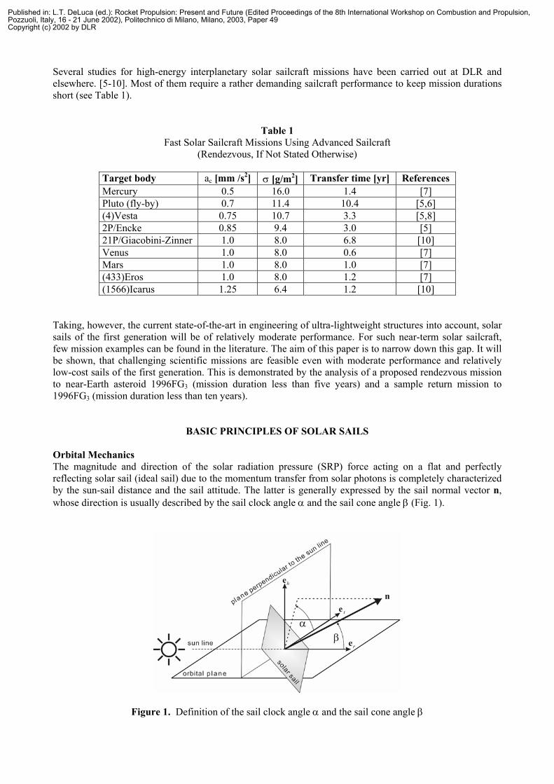
Orbital Mechanics The magnitude and direction of the solar radiation pressure (SRP) force acting on a flat and perfectly reflecting solar sail (ideal sail) due to the momentum transfer from solar photons is completely characterized by the sun-sail distance and the sail attitude. The latter is generally expressed by the sail normal vector n, whose direction is usually described by the sail clock angle α and the sail cone angle β (Fig. 1).
Figure 1. Definition of the sail clock angle α and the sail cone angle β
Published in: L.T. DeLuca (ed.): Rocket Propulsion: Present and Future (Edited Proceedings of the 8th International Workshop on Combustion and Propulsion,Pozzuoli, Italy, 16 - 21 June 2002), Politechnico di Milano, Milano, 2003, Paper 49Copyright (c) 2002 by DLR

Fig. 2 gives a picture of the forces exerted on an ideal sail of area A by the solar radiation pressure P acting on the sail's center of surface. From the geometry of Fig. 2, the total SRP force FSRP can be easily calculated:
Fr = P A (er · n) er , Fr´ = – P A (er · n) er´ (1)
and making use of er – er´ = 2 (er · n) n:
FSRP = Fr + Fr´ = 2 P A (er · n)2 n = 2 P A cos2β n (2)
Figure 2. Perfect reflection
Thus, in case of perfect reflection, the thrust force is always along the direction of the sail normal vector n. At 1 AU, the solar radiation pressure on a totally absorbing body is (Po)1AU = 4.563 µN/m2. Therefore, the effective pressure acting on an ideally reflecting sail perpendicular to the sun-line is twice this value: 2 (Po)1AU = 9.126 µN/m2. A ‘real’ solar sail, however, is not a perfect reflector and a thorough trajectory analysis must take into account the optical properties of the real sail. Since in this case a small but significant fraction of the incoming sunlight is absorbed or reflected non-specularly, a tangential force component is acting on the real solar sail, so that FSRP is no longer along the direction of n. For preliminary mission analysis, however, this tangential force component may be neglected as long as the sail cone angle β is not extremely large. [11] This is the case for interplanetary transfer trajectories where β is usually less than 50°, and the resulting small angular deviation of FSRP from the sail normal may be compensated by the sail steering strategy. Nonetheless, an overall sail efficiency parameter η should be introduced, which takes into account the reduced magnitude of FSRP due to the non-perfect reflectivity of the sail including its deflection/warping under load. Assuming a conservative sail efficiency of η ≈ 0.85 (aluminum coated plastic film), we get
(Peff)1AU = 2 η (Po)1AU = 7.757 µN/m2 (3)
for the effective pressure acting at 1 AU on a solar sail that is oriented perpendicular to the sun-line and
FSRP = (Peff)1AU·2
r1AU
A cos2β n (4)
for the SRP force at a distance r from the sun. Thus, to experience a reasonable acceleration, solar sailcraft must be large and very lightweight. The orbital dynamics of solar sailcraft is in many respects similar to the orbital dynamics of other spacecraft, where a small continuous thrust is applied to modify the spacecraft's orbit over an extended period of time. However, other continuous thrust spacecraft (e.g. using electric propulsion) may orient its thrust vector into any desired direction and vary its thrust level within a wide range, whereas the thrust vector of a solar sail is constrained to lie on the surface of a ‘bubble’ directed away from the sun (see Fig. 3). Nevertheless, by controlling the sail orientation relative to the sun, solar sailcraft can gain orbital angular momentum (if
Published in: L.T. DeLuca (ed.): Rocket Propulsion: Present and Future (Edited Proceedings of the 8th International Workshop on Combustion and Propulsion,Pozzuoli, Italy, 16 - 21 June 2002), Politechnico di Milano, Milano, 2003, Paper 49Copyright (c) 2002 by DLR
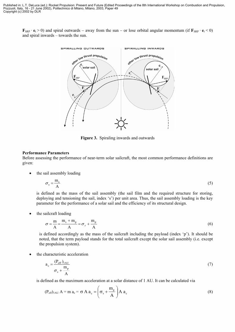
FSRP · et > 0) and spiral outwards – away from the sun – or lose orbital angular momentum (if FSRP · et < 0) and spiral inwards – towards the sun.
Figure 3. Spiraling inwards and outwards Performance Parameters Before assessing the performance of near-term solar sailcraft, the most common performance definitions are given:
• the sail assembly loading
Ams
s =σ (5)
is defined as the mass of the sail assembly (the sail film and the required structure for storing, deploying and tensioning the sail, index ‘s’) per unit area. Thus, the sail assembly loading is the key parameter for the performance of a solar sail and the efficiency of its structural design.
• the sailcraft loading
Am
Amm
Am pps +=
+== sσσ (6)
is defined accordingly as the mass of the sailcraft including the payload (index ‘p’). It should be noted, that the term payload stands for the total sailcraft except the solar sail assembly (i.e. except the propulsion system).
• the characteristic acceleration
Am
)(Pap
s
1AUeffc
+=σ
(7)
is defined as the maximum acceleration at a solar distance of 1 AU. It can be calculated via
(Peff)1AU A = m ac = cp
sc aAAm
aA
+σ=σ (8)
Published in: L.T. DeLuca (ed.): Rocket Propulsion: Present and Future (Edited Proceedings of the 8th International Workshop on Combustion and Propulsion,Pozzuoli, Italy, 16 - 21 June 2002), Politechnico di Milano, Milano, 2003, Paper 49Copyright (c) 2002 by DLR
Using the characteristic acceleration, the SRP force acting on the sail can be written as
FSRP = m ac 2
r1AU
cos2β n (9)
• the lightness number
2c
mm/s 5.93aλ = (10)
which is defined as the ratio of the SRP acceleration experienced by a solar sail perpendicular to the sun-line and the solar gravitational acceleration (5.93 mm/s2 at 1 AU). Using the lightness number, the SRP force acting on the sail can be written as
FSRP = 2rµmλ cos2β n (11)
where . Since both accelerations have an inverse square variation in r, the lightness of solar sailcraft is – unlike the maximum acceleration – independent of the sun-sail distance.
sunGM µ =
GROUND-BASED DEMONSTRATION OF SOLAR SAIL TECHNOLOGY AT DLR
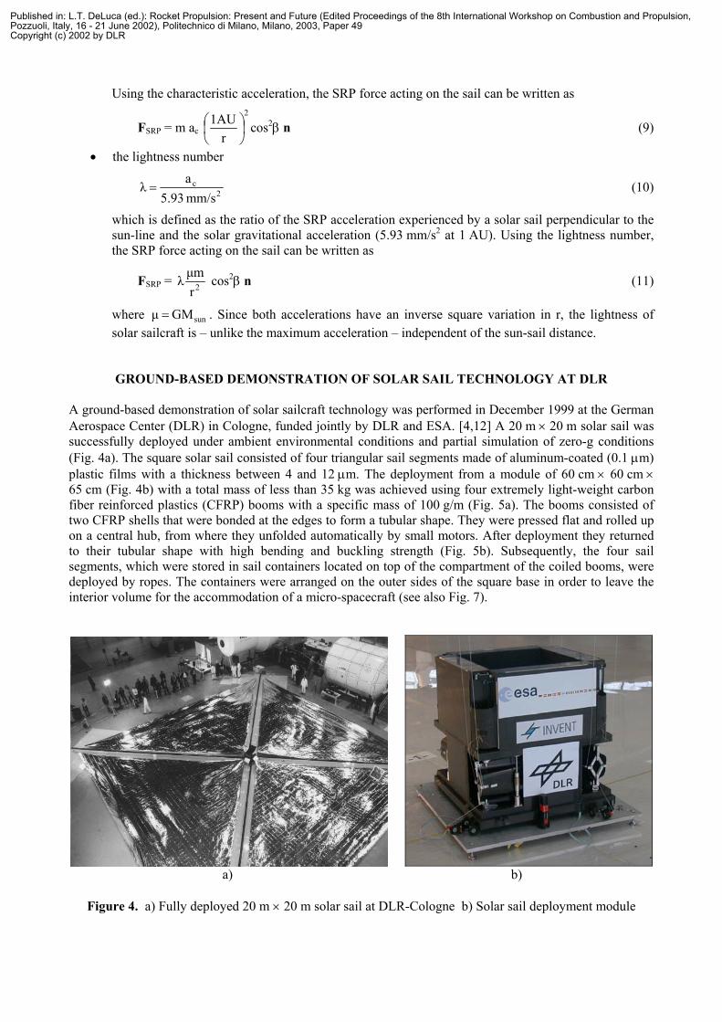
A ground-based demonstration of solar sailcraft technology was performed in December 1999 at the German Aerospace Center (DLR) in Cologne, funded jointly by DLR and ESA. [4,12] A 20 m × 20 m solar sail was successfully deployed under ambient environmental conditions and partial simulation of zero-g conditions (Fig. 4a). The square solar sail consisted of four triangular sail segments made of aluminum-coated (0.1 µm) plastic films with a thickness between 4 and 12 µm. The deployment from a module of 60 cm × 60 cm × 65 cm (Fig. 4b) with a total mass of less than 35 kg was achieved using four extremely light-weight carbon fiber reinforced plastics (CFRP) booms with a specific mass of 100 g/m (Fig. 5a). The booms consisted of two CFRP shells that were bonded at the edges to form a tubular shape. They were pressed flat and rolled up on a central hub, from where they unfolded automatically by small motors. After deployment they returned to their tubular shape with high bending and buckling strength (Fig. 5b). Subsequently, the four sail segments, which were stored in sail containers located on top of the compartment of the coiled booms, were deployed by ropes. The containers were arranged on the outer sides of the square base in order to leave the interior volume for the accommodation of a micro-spacecraft (see also Fig. 7).
a) b)
Figure 4. a) Fully deployed 20 m × 20 m solar sail at DLR-Cologne b) Solar sail deployment module
Published in: L.T. DeLuca (ed.): Rocket Propulsion: Present and Future (Edited Proceedings of the 8th International Workshop on Combustion and Propulsion,Pozzuoli, Italy, 16 - 21 June 2002), Politechnico di Milano, Milano, 2003, Paper 49Copyright (c) 2002 by DLR

To assess the handling behavior of different sail materials, the sail segments were made of three different aluminum-coated plastic films: 12 µm Mylar, 7.5 µm Kapton and 4 µm PEN. All segments were reinforced along the three edges of the triangle to prevent rips. The specific mass of the sail film was 18.9, 12.4 and 10.5 g/m2 respectively. The deployment module and the cross section of the booms for this ground-based demonstration were actually dimensioned for a 40 m × 40 m solar sail. According to FEM (Finite Element Method) calculations, similar booms could be used also for larger sails. [13]
a) b)
Figure 5. a) Conceptual design of the deployment module b) Deployable CFRP boom
PROPOSED FUTURE SOLAR SAIL MISSIONS
Design Requirements Looking at Eq. 7 for the characteristic acceleration of solar sailcraft with a square sail of side length s (so that A = s2), one can see that the performance depends on three design parameters, defining a three-dimensional design space: the sail assembly loading σs, the payload mass mp and the side length s. Fig. 6 shows a section of this design space for fixed characteristic acceleration ac = 0.1 mm/s2, since this seems to represent a ‘lower bound’ for useful acceleration levels within typical high-energy planetary missions. [14] The diagram shows that the sail used for the ground demonstration with s = 20 m and σs = 87.5 g/m2 cannot achieve an acceleration of 0.1 mm/s2 (however, some payload mass could be accommodated for a smaller ac). To reach acceptable acceleration levels and payload masses, Fig. 6 shows that the sail side length has to be increased significantly and the assembly loading has to be reduced additionally, e.g. to σs = 40 g/m2 with s = 40 m (near-term technology) and σs = 20 g/m2 with s = 70 m (mid-term technology). By different combinations of the three design parameters, any desired characteristic acceleration can be achieved. An increase in payload mass can, for example, be offset with a proportional increase of s2, or with an adequate decrease of σs. It should be noted that – strictly speaking – only mp and s can be chosen independently, whereas – for a fixed design and technology– σs(s) is a function of s with ∂σs/∂s < 0 (i.e. the mass of the booms and the deployment module scale less than linearly with the sail area). Space Deployment Test DLR, ESA and industry are presently involved in the advanced definition phase for an in-orbit deployment test, using an upgraded version of the current solar sail breadboard model. The proposal is to launch a sail deployment experiment aboard a modified SS-18 ballistic missile into low Earth orbit. During the test, the sail would stay attached to the orbital bus structure, which provides attitude control and power. The main objective would be to verify the functionality of the design concept and deployment mechanisms under the conditions of the space environment.
CFRP Booms
Sail Containers(open)
Published in: L.T. DeLuca (ed.): Rocket Propulsion: Present and Future (Edited Proceedings of the 8th International Workshop on Combustion and Propulsion,Pozzuoli, Italy, 16 - 21 June 2002), Politechnico di Milano, Milano, 2003, Paper 49Copyright (c) 2002 by DLR
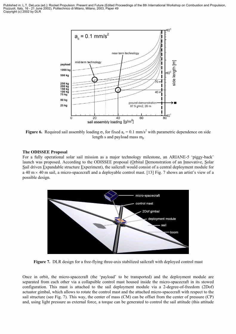
Figure 6. Required sail assembly loading σs for fixed ac = 0.1 mm/s2 with parametric dependence on side length s and payload mass mp
The ODISSEE Proposal For a fully operational solar sail mission as a major technology milestone, an ARIANE-5 ‘piggy-back’ launch was proposed. According to the ODISSEE proposal (Orbital Demonstration of an Innovative, Solar Sail driven Expandable structure Experiment), the sailcraft would consist of a central deployment module for a 40 m × 40 m sail, a micro-spacecraft and a deployable control mast. [13] Fig. 7 shows an artist’s view of a possible design.
Figure 7. DLR design for a free-flying three-axis stabilized sailcraft with deployed control mast
Once in orbit, the micro-spacecraft (the ‘payload’ to be transported) and the deployment module are separated from each other via a collapsible control mast housed inside the micro-spacecraft in its stowed configuration. This mast is attached to the sail deployment module via a 2-degree-of-freedom (2Dof) actuator gimbal, which allows to rotate the control mast and the attached micro-spacecraft with respect to the sail structure (see Fig. 7). This way, the center of mass (CM) can be offset from the center of pressure (CP) and, using light pressure as external force, a torque can be generated to control the sail attitude (this attitude
Published in: L.T. DeLuca (ed.): Rocket Propulsion: Present and Future (Edited Proceedings of the 8th International Workshop on Combustion and Propulsion,Pozzuoli, Italy, 16 - 21 June 2002), Politechnico di Milano, Milano, 2003, Paper 49Copyright (c) 2002 by DLR

control concept was originally proposed by [15]). The length of the control mast – typically approx. 10 m – is optimized in order to achieve the highest angular acceleration levels possible (at 1 AU, a 90° turn takes approx. 10 minutes). An active attitude control system with gas thrusters may be installed in the micro-spacecraft as an additional option. Once the central mast is latched in its final length and system checkouts have been performed, boom deployment is initiated. The four supporting booms are unrolled from the central deployment module and the four folded triangular sail film segments are released from the sail containers. Sail deployment would be observed by several wide- and narrow-field cameras mounted on the spacecraft. As part of the primary mission objectives, performance as well as maneuverability tests would be executed. The sailcraft could perform a low-thrust spiral orbit-raising in order to conduct a lunar fly-by, or enter an elliptical orbit about the Moon. Main design driver for this concept is the launch option as a ‘piggy-back’ payload on the ASAP-5 ring structure of ARIANE-5, where the payload volume is restricted to 60 cm × 60 cm × 80 cm and the mass must be less than 100 kg. The ENEAS Proposal Near-Earth asteroids (NEAs) are a promising category of target bodies for a first science-driven solar sailcraft mission, since they can be accessed relatively easily and are of great scientific relevance. Therefore, a NEA fly-by and rendezvous mission called ENEAS (Exploration of Near-Earth Asteroids with a Sailcraft) has been proposed in 2000 by DLR in cooperation with the Westfälische Wilhelms-University at Münster, Germany, as a candidate within the German small satellite program for space sciences [12,16]. Based on the successful deployment experiment described above, ENEAS is intended to feature a deployable (50 m)2 solar sail with a mass of 73 kg as the propulsion system that would be capable to transport a micro-satellite with a mass of 66 kg to several NEAs within less than five years (Figs. 8 and 9).
a) b)
Figure 8. ENEAS sailcraft a) launch configuration; b) deployed configuration
Published in: L.T. DeLuca (ed.): Rocket Propulsion: Present and Future (Edited Proceedings of the 8th International Workshop on Combustion and Propulsion,Pozzuoli, Italy, 16 - 21 June 2002), Politechnico di Milano, Milano, 2003, Paper 49Copyright (c) 2002 by DLR

Figure 9. Rendezvous trajectory to 1996FG3 for ac = 0.14 mm/s2 (C3 = 0 km2/s2)
Table 2 Parameters for the Proposed ENEAS and ENEAS-SR Missions
ENEAS ENEAS-SR sail area A (50 m)2 (70 m)2 sail assembly loading σs 29.2 g/m2 29.2 g/m2 sail assembly mass ms 73 kg 143 kg payload mass mp 65.5 kg 237 kg total sailcraft mass M 138.5 kg 380 kg sailcraft loading σ 55.4 g/m2 77.6 g/m2 lightness number λ 1/42.4 1/59.3 characteristic acceleration ac 0.14 mm/s2 0.10 mm/s2 Characteristic SRP force FSRP,c 19.5 mN 38.0 mN
Table 2 summarizes the ENEAS parameters. The central objectives for the mission were twofold: To explore in detail a NEA in a rendezvous as well as one or more NEAs during fly-bys, and to technically demonstrate the abilities of solar sail propulsion and maneuvering in deep space. The proposed minimum scientific payload accommodated on the micro-spacecraft consisted of instruments for remote sensing with a mass of about 5 kg (CCD camera + IR spectrometer + magnetometer). 1996FG3 was chosen as the main target object, since it has orbital elements not too different from those of the Earth and since it is an object of exceptional scientific relevance. Observations indicate that 1996FG3 is a binary asteroid, consisting of a central body – diameter in the order of 1.4 km – with a rotation period of about 3.6 hours and a smaller satellite with an orbital period of about 16.15 hours. The determined average bulk density is 1.4 ± 0.3 g/cm3, which is highly suggestive of a ‘rubble pile’ structure. [17] Recently performed trajectory optimization based on artificial neural networks and evolutionary algorithms revealed that the ENEAS sailcraft can rendezvous with 1996FG3 in 4.35 years (1588 days), if it is inserted directly into an interplanetary trajectory with zero hyperbolic excess velocity. [18] The new optimization method produced a better trajectory for the same launch date), being closer to the (unknown) global optimum, than earlier calculations based on traditional numerical optimal control methods. [12,16] The flight time could be shortened by 52 days, reducing at the same time the C3-requirement from 4 to 0 km2/s2, thus permitting a reduction of launch cost. The accuracy of
Published in: L.T. DeLuca (ed.): Rocket Propulsion: Present and Future (Edited Proceedings of the 8th International Workshop on Combustion and Propulsion,Pozzuoli, Italy, 16 - 21 June 2002), Politechnico di Milano, Milano, 2003, Paper 49Copyright (c) 2002 by DLR

the trajectory generated by the evolutionary artificial neural network is ∆r < 11000 km for the distance to the target body at rendezvous and ∆V < 43 m/s for the relative velocity (even without performing a local fine tuning of the trajectory). [18] Fig. 9 shows the transfer trajectory from Earth to 1996FG3 with a launch on August 13th, 2006, and a rendezvous on December 18th, 2010. The launch vehicle – potentially a Russian ballistic missile – would insert the sailcraft into an interplanetary trajectory with zero hyperbolic excess velocity. During the transfer, the sailcraft will operate with high autonomy, so that attitude and navigation monitoring from ground will be carried out on a weekly basis only. Both, the use of a gimbaled mast attitude control system and the use of cold-gas or liquid thrusters are under consideration. ENEAS with Sample Return To study the 1996FG3 system in more detail, it would be necessary to place a lander on the surface of the asteroid (e.g. for mass spectrometry and/or alpha/proton/X-ray spectrometry). Some investigations – like the precise age determination – could probably only be achieved by taking samples back to Earth. Due to their unlimited ∆V-capability, solar sailcraft are especially suited for such sample return missions. Compared to the ENEAS rendezvous mission, however, the payload mass has to be increased considerably. The diagram in Fig. 6 shows the required sail size to obtain a characteristic acceleration of 0.1 mm/s2 for different sail assembly loadings and payload masses. We consider a maximum sail size of (70 m)2 with a sail assembly loading of 29.2 g/m2 (sail film + booms + deployment module) a realistic – however still challenging – baseline for a medium-term ENEAS Sample Return (ENEAS-SR) mission. The specified σs and s yield a payload mass of 237 kg. Current research at our department indicates the feasibility of the mission within the specified mass budget, including a 140 kg lander with a sample return capsule. The design of the capsule with a mass of about 45 kg integrates features of the US Stardust and the Japanese Muses-C capsules. Table 2 displays also these ENEAS-SR parameters. Trajectory calculations show, that the mission can be achieved within less than ten years, even with the low characteristic acceleration of 0.1 mm/s2. This includes a rendezvous trajectory of 6.27 years (Fig. 10a), 340 days of operations at the asteroid and an Earth return trajectory of 2.20 years (Fig. 10b). For a discussion of the question “is this long mission duration still acceptable?” a qualitative comparison with conventional propulsion including (eventually multiple) gravity assist maneuvers may help. The corresponding ∆V-requirement for chemical propulsion would be about 6 to 10 km/s. Therefore, either an expensive launch vehicle and heavy spacecraft is required, resulting in a relatively short trip time of a few years, or several gravity assists would be needed for a cheaper mission,
a) b)
Figure 10. ENEAS-SR trajectories; a) rendezvous trajectory to 1996FG3 b) landing/sampling period at 1996 FG3 (dashed line) and Earth return trajectory
Published in: L.T. DeLuca (ed.): Rocket Propulsion: Present and Future (Edited Proceedings of the 8th International Workshop on Combustion and Propulsion,Pozzuoli, Italy, 16 - 21 June 2002), Politechnico di Milano, Milano, 2003, Paper 49Copyright (c) 2002 by DLR

leading to a long trip time comparable to the Rosetta mission to comet 46P/Wirtanen. The Rosetta mission will have three intermediate gravity assist maneuvers (Mars-Earth-Earth) and a trip time of approximately nine years. Since we aim at a low-cost approach, only the gravity assist option is a reasonable conventional alternative. Thus, we think that a mission duration of less than ten years seems acceptable. As in the case of ENEAS, the launcher will insert the ENEAS-SR sailcraft directly into an interplanetary trajectory with C3 = 0 km2/s2, since for solar sailcraft of moderate performance gaining orbital energy in the Earth's gravitational field is difficult and time consuming. The final rendezvous with 1996FG3 is planned within its gravitational sphere of influence (Hill-sphere) of between 70 and 150 km radius (at perihelion and aphelion respectively), considering that the asteroid’s orbit is considerably elliptical. Even in the near-field of the asteroid, the SRP acceleration (between 0.21 and 0.05 mm/s2 at perihelion and aphelion respectively) is much larger than the asteroid's gravitational acceleration (0.01 to 0.00005 mm/s2 at a distance ranging from 5 to 50 km). Therefore, the sailcraft is able to hover on an artificial equilibrium surface in the hemisphere around the asteroid that is opposite to the sun (Fig. 11a). Those quasi-stationary hovering positions are unstable but can be stabilized using a feedback control loop. [19] Hovering near the asteroid, the (likely
a) b)
Figure 11 a) Artificial equilibrium points and hovering within the gravitational sphere of influence (Hill-sphere) of the asteroid b) Orbiter and lander design for ENEAS-SR
complex) gravitational field of the target object is studied. Thereafter, the lander with the Sample Return Capsule (SRC) is separated from the solar sail to go into closer orbits about the asteroid (Fig. 11b). Due to the extremely low ∆V-requirements of only a few m/s, a cold gas propulsion system with a propellant mass of a few kg will suffice to perform all lander operations. The orbit is continuously lowered until a safe landing trajectory can be computed. Once landed, a special sampling device, derived from PLUTO (Planetary Underground Tool), which is presently developed by DLR for the Beagle 2 lander on ESA’s Mars Express mission, will be expelled from the SRC on the lander into the surface. [20] The device consists of a self-penetrating tethered mole, which will go down into the soil to about one or two meters depth without any reaction forces on the lander. Material from the asteroid will be collected and stored in the sample chamber of the mole. Afterwards, the mole is retracted into the lander and fed back directly into the SRC. Since 1996FG3 is a binary system, it would be interesting to land on and extract samples from both bodies to investigate the origin and the collisional evolution of the system. At the end of this phase, the lander returns to the sailcraft, which is waiting edge-on at the L2 Lagrange point (so that no SRP force is acting on the sail) to assist the automatic rendezvous. After redocking, the ENEAS-SR solar sailcraft returns to Earth with the SRC. A detailed design of the lander, the sample extraction mechanisms and the subsystems that are required to rendezvous the waiting sailcraft requires further studies and is beyond the scope of this paper. The return trajectory is much shorter than the initial transfer trajectory, since no rendezvous is required at Earth. Just
Published in: L.T. DeLuca (ed.): Rocket Propulsion: Present and Future (Edited Proceedings of the 8th International Workshop on Combustion and Propulsion,Pozzuoli, Italy, 16 - 21 June 2002), Politechnico di Milano, Milano, 2003, Paper 49Copyright (c) 2002 by DLR
before the arrival at Earth, the SRC is separated from the lander and injected into an Earth reentry trajectory, where it is decelerated by atmospheric friction and breaking parachutes. The sailcraft arrives with a relatively large hyperbolic excess velocity of about 8.4 km/s. The gravitational acceleration of Earth adds another 11.2 km/s, so that the Earth reentry velocity may reach about (8.42 + 11.22)0.5 km/s = 14.0 km/s.
CONCLUSIONS
We have investigated various near-term missions for solar sailcraft and their performance requirements. The minimum characteristic acceleration should not be less than 0.1 mm/s2 in order to avoid unacceptable long mission durations even for relatively easily accessible inner solar system bodies. A (70 m)2 solar sail with a sail assembly loading of 29.2 g/m2 (sail film + booms + deployment module) was considered to be a realistic – however still challenging – near- to medium-term baseline. With this solar sail, a characteristic thrust of 38 mN can be achieved. We have also demonstrated that a sample return mission to a near-Earth asteroid with such a solar sail is feasible within a mission duration of less than ten years. In addition to the scientific value of such a mission, the demonstration of the technical capabilities of solar sail propulsion in deep space would be a central objective.
ACKNOWLEDGEMENTS
The authors want to thank the ENEAS-team (see [16]) for many important inputs during the definition of the ENEAS mission concept as well as Faizal Allaudin from International Space University (ISU) and Lutz Richter from DLR for significant support on the design of the ENEAS-SR lander and the sample extraction mechanisms.
REFERENCES
[1] K.E. Tsiolkowski. Extension of man into outer space, 1921. [2] F.A. Tsander. From a scientific heritage. NASA technical translation, 1967. TTF-541. [3] M. Leipold, D. Kassing, M. Eiden, L. Herbeck. Solar sails for space exploration – the development
and demonstration of critical technologies in partnership. ESA bulletin 98, June 1998. [4] M. Leipold, M. Eiden, C.E. Garner, L. Herbeck, D. Kassing, T. Niederstadt, T. Krüger, G. Pagel, M.
Rezazad, H. Rozemeijer, W. Seboldt, C. Schöppinger, C. Sickinger, W. Unkenbold. Solar sail technology development and demonstration. Laurel, 2000. 4th IAA International Conference on Low-Cost Planetary Missions. IAA-L-0707.
[5] M. Leipold. Solar sail mission design. Doctoral thesis, Lehrstuhl für Flugmechanik und Flugregelung;
Technische Universität München, 1999. DLR-FB-2000-22. [6] M. Leipold. To the sun and Pluto with solar sails and micro-sciencecraft. Acta Astronautica, 45(4-
9):549-555, 1999. [7] C.G. Sauer. Optimum solar-sail interplanetary trajectories. San Diego, August 2000. AIAA/AAS
Astrodynamics Conference. 76-792. [8] M. Leipold, E. Pfeiffer, P. Groepper, M. Eiden, W. Seboldt, L. Herbeck, W. Unkenbold. Solar sail
technology for advanced space science missions. Toulouse, 2001. 52nd International Astronautical Congress. IAF-01-S.6.10.
[9] M. Leipold, W. Seboldt, S. Lingner, E. Borg, A. Herrmann, A. Pabsch, O. Wagner, J. Brückner.
Mercury sun-synchronous polar orbiter with a solar sail. Acta Astronautica, 39(1-4):143-151, 1996.
Published in: L.T. DeLuca (ed.): Rocket Propulsion: Present and Future (Edited Proceedings of the 8th International Workshop on Combustion and Propulsion,Pozzuoli, Italy, 16 - 21 June 2002), Politechnico di Milano, Milano, 2003, Paper 49Copyright (c) 2002 by DLR

[10] J.L. Wright. Space Sailing. Gordon and Breach Science Publishers, Philadelphia, 1992. [11] C.R. McInnes. Solar Sailing. Technology, Dynamics and Mission Applications. Springer-Praxis Series
in Space Science and Technology. Springer-Praxis, Berlin, Heidelberg, New York, Chicester, 1999. [12] W. Seboldt, M. Leipold, M. Rezazad, L. Herbeck, W. Unkenbold, D. Kassing, M. Eiden. Ground-
based demonstration of solar sail technology. Rio de Janeiro, 2000. 51st International Astronautical Congress. IAF-00-S.6.11.
[13] M. Leipold, C.E. Garner, R. Freeland, A. Herrmann, M. Noca, G. Pagel, W. Seboldt, G. Sprague, W.
Unckenbold. ODISSEE - a proposal for demonstration of a solar sail in earth orbit. Acta Astronautica, 45(4-9):557-566, 1999.
[14] B. Dachwald, W. Seboldt, B. Häusler. Performance requirements for near-term interplanetary solar
sailcraft missions. Versailles, 2002. 6th AAAF International Symposium on Space Propulsion: Propulsion for Space Transportation of the XXIst Century.
[15] F. Angrilli, S. Bortolami. Attitude and orbital modelling of solar-sail spacecraft. ESA Journal, 14:431-
446, 1990. [16] E.K. Jessberger, W. Seboldt, K.-H. Glassmeier, G. Neukum, M. Pätzold, G. Arnold, H.-U. Auster, D.
deNiem, F. Guckenbiehl, B. Häusler, G. Hahn, N. Hanowski, A. Harris, H. Hirsch, E. Kührt, M. Leipold, E. Lorenz, H. Michaelis, D. Möhlmann, S. Mottola, D. Neuhaus, H. Palme, H. Rauer, M. Rezazad, L. Richter, D. Stöffler, R. Willnecker, J. Brückner, G. Klingelhöfer, T. Spohn. ENEAS - exploration of near-Earth asteroids with a sailcraft. Proposal for a Small Satellite Mission within the Space Sciences Program of DLR, August 2000.
[17] S. Mottola F. Lahulla. Mutual eclipse events in asteroidal binary system 1996FG3: Observations and a
numerical model. Icarus, 146:556-567, 2000. [18] B. Dachwald, W. Seboldt. Optimization of interplanetary rendezvous trajectories for solar sailcraft
using a neurocontroller. Monterey, August 2002. AIAA/AAS Astrodynamics Specialist Conference. AIAA-2002-4989.
[19] E. Morrow, D.J. Scheeres, D. Lubin. Solar sail orbit operations at asteroids. Journal of Spacecraft and
Rockets, 38:279-286, 2001. [20] L. Richter, P. Coste, V. Gromov, H. Kochan, S. Pinna, H.E. Richter. Development of the „Planetary
Underground Tool” subsurface soil sampler for the Mars Express “Beagle 2” lander. Advanced Space Research, 28(8):1225-1230, 2001.
Published in: L.T. DeLuca (ed.): Rocket Propulsion: Present and Future (Edited Proceedings of the 8th International Workshop on Combustion and Propulsion,Pozzuoli, Italy, 16 - 21 June 2002), Politechnico di Milano, Milano, 2003, Paper 49Copyright (c) 2002 by DLR