solar thermal energy - stations controllers, …...oventrop systems for solar thermal energy are...
TRANSCRIPT

Solar thermal energyStations, controllers, collectors, accessories,
service, software
Product range
Valves, controls + systems
Awards:
MADE IN GERMANY
Innovation + Quality

2
Stations for solar plants and solid fuel boiler connection are becoming more and more important.The reasons are not at last the rising energy prices and the changing environmentalconsciousness of consumers.These stations are not only installed in new buildings, but also existing systems are increasingly converted.
The use of solar energy for heat generation is a good opportunity to reduce energy costs in combination with gas/heating oil gross calorifi c boilers.
Example: Construction of a solar plant in a detached house
Solar thermal energyContent
ContentPage 2 Content
3 Signifi cance of solar energy 4 Solar hot potable water preparation and support of the heating system 5 “OKP-10/20” Tube collector 6 “OKF” Flat-plate collector 7 “Regusol-130” Stations 8 “Regusol-180” Stations 9 “Regusol X-Uno” Station with heat exchanger10 “Regusol X-Duo” Station with heat exchanger 11 Hot potable water preparation and support of the heating system – Buffer storage cylinder and station for hot potable water
preparation “Regumaq X” – System illustration 12 Hot potable water preparation and support of the heating system – Buffer storage cylinder and station for hot potable water
preparation “Regumaq X” – Loading section by section with station “Regusol X-Duo” – System illustration13 “Regumaq X-30/XZ-30” Stations for hot potable water preparation
14 “Regumaq K” Cascade control set for hot potable water preparation – Control concepts
15 “Regtronic” Controllers for solar and heating technology
16 “Regucor WHS” Energy storage centre
17 “Hydrocor” Storage cylinders
18 “Solar” Diaphragm expansion tanks, in-line tanks – Pipes and fi ttings
19 Further products for thermal solar energy
20 Service, software
3
Significance of solar ene gy
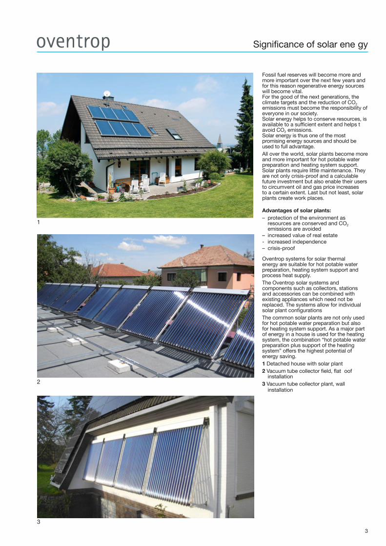
Fossil fuel reserves will become more and more important over the next few years and for this reason regenerative energy sources will become vital. For the good of the next generations, the climate targets and the reduction of CO2 emissions must become the responsibility of everyone in our society. Solar energy helps to conserve resources, is available to a sufficient extent and helps t avoid CO2 emissions. Solar energy is thus one of the most promising energy sources and should be used to full advantage.All over the world, solar plants become more and more important for hot potable water preparation and heating system support. Solar plants require little maintenance. They are not only crisis-proof and a calculable future investment but also enable their users to circumvent oil and gas price increases to a certain extent. Last but not least, solar plants create work places.
Advantages of solar plants: – protection of the environment as
resources are conserved and CO2 emissions are avoided
– increased value of real estate- increased independence– crisis-proof
Oventrop systems for solar thermal energy are suitable for hot potable water preparation, heating system support and process heat supply.The Oventrop solar systems and components such as collectors, stations and accessories can be combined with existing appliances which need not be replaced. The systems allow for individual solar plant configurations The common solar plants are not only used for hot potable water preparation but also for heating system support. As a major part of energy in a house is used for the heating system, the combination “hot potable water preparation plus support of the heating system” offers the highest potential of energy saving.1 Detached house with solar plant2 Vacuum tube collector field, flat oof
installation3 Vacuum tube collector plant, wall
installation
1
3
2

4
Solar hot potable water preparation andsupport of the heating system
Function of a solar thermal plant for hot potable water preparationThe heat transfer liquid is heated by the sun via the collector absorber. The solar liquid is transported by the station’s circulation pump to the lower heat exchanger, for instance a bivalent potable water storage cylinder, where heat is transmitted to the potable water.The circulation pump in the solar circuit is only activated by the solar controller if the temperature in the collector is higher than the temperature in the lower section of the storage cylinder. The temperature difference is detected by temperature sensors at the collector and the bivalent storage cylinder.Depending on the temperature difference, the flow rate of the solar liquid is inc eased or reduced. This way, an optimum solar heat return and suitable temperatures inside the storage cylinder are achieved.In central Europe up to 60-70% of the energy demand for hot potable water preparation can be saved.If solar radiation is not intense enough for hot potable water preparation, the required energy must be supplied by another heating system.1 Basic illustration of a solar plant for hot potable water preparation2 Switching diagram with bivalent potable water storage cylinder
Function of a solar thermal plant for hot potable water preparation and support of the heating system
The function of a solar thermal plant for support of the heating system is similar to that of a solar plant for hot potable water preparation described before. The collector surface of a solar plant for support of the heating system is larger than that for hot potable water preparation only. Correctly dimensioned and installed solar plants can supply up to about 15 – 20% of the total energy demand (hot potable water preparation and support of the heating system). Heat storage is different. The heat is stored in solar buffer storage cylinders for instance. Hot potable water preparation is carried out by heat exchanger stations “Regumaq X”.Integration of the heating system is frequently carried out by a return temperature increase of the heating circuit. If the temperature in the storage cylinder is higher than the heating return temperature, a three-way diverting valve “Tri-D TR” is operated and leads the heating return through the storage cylinder where it heats the water. If the storage cylinder temperature is too low, the heating return is warmed up by the conventional heating system.3 Basic illustration of a solar plant with heating system support4 Switching diagram with return temperature increase
1
2
3
4
Solar hot potable water preparationDuring the summer months, the energy required for hot potable water preparation can be covered completely by a professionally dimensioned and installed solar thermal plant.The Oventrop solar thermal system for hot potable water preparation consists basically of the following main components:1. the collector field consisting of “OKP
vacuum tube collectors or high-capacity flat-plate collectors “OKF
2. the solar station “Regusol” with integrated control for heat transport and the necessary safety devices
3. the solar buffer storage cylinder or bivalent potable water storage cylinder
Solar hot potable water preparation and support of the heating systemThe Oventrop solar thermal system for hot potable water preparation and support of the heating system consists of the following main components:1. the collector field consisting of “OKP
vacuum tube collectors or high-capacity flat-plate collectors “OKF
2. the solar station “Regusol” with integrated control for heat transport and the necessary safety devices. The existing boiler can also be blocked or activated.
3. the solar buffer storage cylinder and the buffer storage cylinder
“Brawa-Mix”
WH
C
Collector “OKF/OKP”
“Regusol EL”“Regumat M3”
Three-way diverting valve “Tri-D TR”
SupplyReturnControl line for boiler control
Collector “OKF/OKP”
“Regumat M3”
Three-way diverting valve “Tri-D TR”
Solar buffer storage cylinder
Solar buffer storage cylinder
“Regumaq X”
SupplyReturnControl line for boiler controlInternal terminal
“Regusol EL”

1
l
lllll
2
3 4
The tube collector “OKP-10/20” is a heat pipe tube collector which distinguishes itself by a permanent heat transport. Due to its hydronic features, the collector can be fi xed to the building (pitched or fl at roof, facade or detached) with an inclination of the axis between 15° and 75°.The tube collector can be used for heating of potable or swimming pool water, solar support of the heating system and the production of process heat.Due to the high-selective absorber surface, a high solar share is achieved.The vacuum inside the tube guarantees maximum insulation. The high quality corrosion resistant materials ensure a long service life of the tube collector “OKP-10/20.1 Tube collector “OKP-10/20”tested to DIN EN 12975 and certifi ed according to “SolarKeymark”. According to the ITW basic rules, the annual collector heat return amounts to 683 kW h/m². The collector heat return forecast is based on an aperture surface area of 3 m² (small illustr.: Foot rail with stainless steel angular plate for additional protection of the vacuum tubes on the roof)2 Illustrated section tube collector “OKP-10/20”Function:- Sunlight is absorbed and converted into
heat- Heat is transmitted to the heat pipe via the
heat conducting steel sheet inside the glass tube
- Liquid inside the heat pipe evaporates; steam rises into the condenser
- Heat is transmitted to the passing heat transfer medium via the double tube heat exchanger (collector) in which the condenser is located
- Liquid inside the condenser condenses due to the heat output, fl ows back inside the heat pipe and the procedure is repeated
3 System illustration solar circuit with collector4 System illustration solar circuit with collector)Award:
“OKP-10/20” Tube collector
5
Return
Supply
Permanent heat transport
German Designer ClubGood Design
Collectors “OKF/OKP”
6
1
2
3
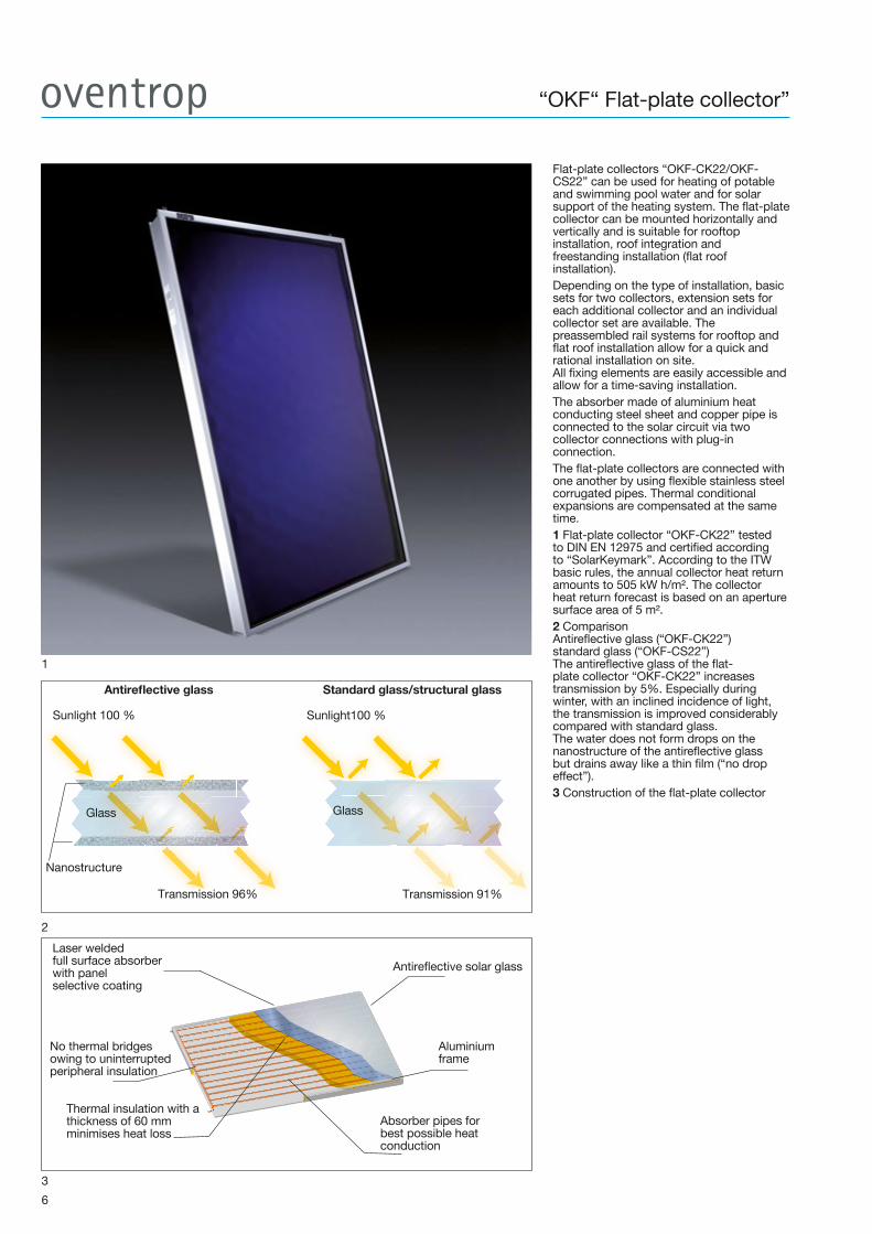
Flat-plate collectors “OKF-CK22/OKF-CS22” can be used for heating of potable and swimming pool water and for solar support of the heating system. The fl at-plate collector can be mounted horizontally and vertically and is suitable for rooftop installation, roof integration and freestanding installation (fl at roof installation).Depending on the type of installation, basic sets for two collectors, extension sets for each additional collector and an individual collector set are available. The preassembled rail systems for rooftop and fl at roof installation allow for a quick and rational installation on site.All fi xing elements are easily accessible and allow for a time-saving installation.The absorber made of aluminium heat conducting steel sheet and copper pipe is connected to the solar circuit via two collector connections with plug-in connection. The fl at-plate collectors are connected with one another by using fl exible stainless steel corrugated pipes. Thermal conditional expansions are compensated at the same time.1 Flat-plate collector “OKF-CK22” tested to DIN EN 12975 and certifi ed according to “SolarKeymark”. According to the ITW basic rules, the annual collector heat return amounts to 505 kW h/m². The collector heat return forecast is based on an aperture surface area of 5 m². 2 ComparisonAntirefl ective glass (“OKF-CK22”)standard glass (“OKF-CS22”)The antirefl ective glass of the fl at-plate collector “OKF-CK22” increases transmission by 5%. Especially during winter, with an inclined incidence of light, the transmission is improved considerably compared with standard glass. The water does not form drops on the nanostructure of the antirefl ective glass but drains away like a thin fi lm (“no drop effect”).3 Construction of the fl at-plate collector
“OKF“ Flat-plate collector”
Antirefl ective glass Standard glass/structural glass
Glass Glass
Nanostructure
Antirefl ective solar glass
Laser weldedfull surface absorberwith panelselective coating
No thermal bridgesowing to uninterruptedperipheral insulation
Thermal insulation with athickness of 60 mmminimises heat loss
Absorber pipes forbest possible heatconduction
Aluminiumframe
Sunlight 100 % Sunlight100 %
Transmission 96% Transmission 91%
4
1
2 3
7
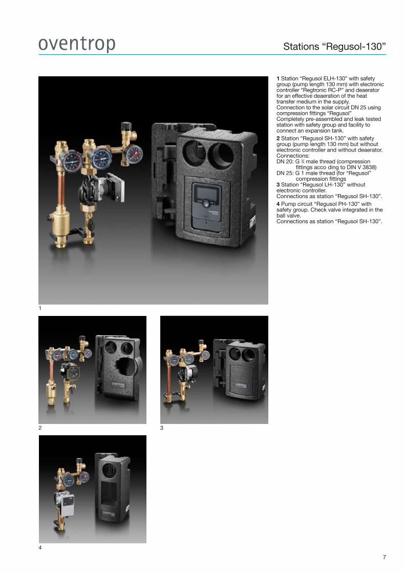
1 Station “Regusol ELH-130” with safety group (pump length 130 mm) with electronic controller “Regtronic RC-P” and deaerator for an effective deaeration of the heat transfer medium in the supply. Connection to the solar circuit DN 25 using compression fittings “Regusol” Completely pre-assembled and leak tested station with safety group and facility to connect an expansion tank.2 Station “Regusol SH-130” with safety group (pump length 130 mm) but without electronic controller and without deaerator. Connections:DN 20: G 3⁄4 male thread (compression
fittings acco ding to DIN V 3838)DN 25: G 1 male thread (for “Regusol”
compression fittings3 Station “Regusol LH-130” without electronic controller. Connections as station “Regusol SH-130”.4 Pump circuit “Regusol PH-130” with safety group. Check valve integrated in the ball valve. Connections as station “Regusol SH-130”.
Stations “Regusol-130”

1 Station “Regusol LH-180” DN 25 with safety group (pump length 180 mm) and deaerator for an effective deaeration of the heat transfer medium in the supply. Connection to the solar circuit DN 25 using compression fittings “Regusol” Completely pre-assembled and leak tested station with safety group and facility to connect an expansion tank.2 Pump circuit “Regusol PH-180” DN 25 with safety group.3 Station “Regusol SH-180” DN 25, same construction as station “Regusol LH-180” but without deaerator.4 Station “Regusol SH-180” DN 32 with safety group. Connection to the solar circuit G 2 flat sealing
8
1
2 3
“Regusol-180” stations
4
9
1
“Regusol X-Uno” Station with heat exchanger
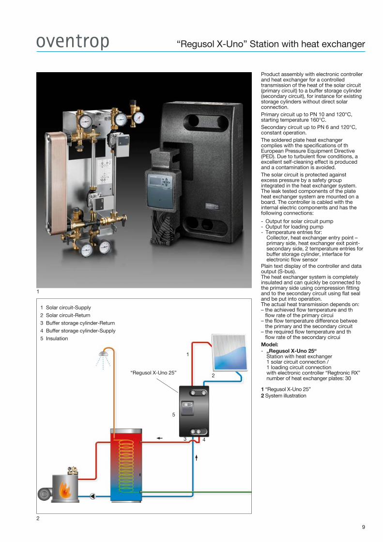
Product assembly with electronic controller and heat exchanger for a controlled transmission of the heat of the solar circuit (primary circuit) to a buffer storage cylinder (secondary circuit), for instance for existing storage cylinders without direct solar connection.Primary circuit up to PN 10 and 120°C, starting temperature 160°C. Secondary circuit up to PN 6 and 120°C, constant operation.The soldered plate heat exchanger complies with the specifications of th European Pressure Equipment Directive (PED). Due to turbulent flow conditions, a excellent self-cleaning effect is produced and a contamination is avoided.The solar circuit is protected against excess pressure by a safety group integrated in the heat exchanger system. The leak tested components of the plate heat exchanger system are mounted on a board. The controller is cabled with the internal electric components and has the following connections:
- Output for solar circuit pump - Output for loading pump- Temperature entries for:
Collector, heat exchanger entry point – primary side, heat exchanger exit point- secondary side, 2 temperature entries for buffer storage cylinder, interface for electronic flow sensor
Plain text display of the controller and data output (S-bus). The heat exchanger system is completely insulated and can quickly be connected to the primary side using compression fitting and to the secondary circuit using flat seal and be put into operation. The actual heat transmission depends on: – the achieved flow temperature and th
flow rate of the primary circui– the flow temperature difference betwee
the primary and the secondary circuit– the required flow temperature and th
flow rate of the secondary circuiModel:- „Regusol X-Uno 25“
Station with heat exchanger 1 solar circuit connection / 1 loading circuit connection with electronic controller “Regtronic RX” number of heat exchanger plates: 30
1 “Regusol X-Uno 25”2 System illustration
2
1 Solar circuit-Supply
2 Solar circuit-Return
3 Buffer storage cylinder-Return
4 Buffer storage cylinder-Supply
5 Insulation
1
2
5
3 4
“Regusol X-Uno 25”

“Regusol X-Duo” Station with heat exchanger
10
1
Product assembly with electronic controller, heat exchanger, three-way conversion valve for second loading circuit for the controlled transmission of the heat of the solar circuit (primary circuit) to a buffer storage cylinder (secondary circuit), for instance for existing storage cylinders without direct solar connection.The three-way valve integrated in the supply pipe of the secondary circuit allows for the conversion to an additional loading circuit running in parallel, for instance for the loading section by section of the storage cylinder or the thermal loading of another storage cylinder. Primary circuit up to PN 10 and 120°C, starting temperature 160°C. Secondary circuit up to PN 6 and 120°C, constant operation.The soldered plate heat exchanger complies with the specifications of the Europea Pressure Equipment Directive (PED). Due to turbulent flow conditions, an excellent selfcleaning effect is produced and a contamination is avoided. The solar circuit is protected against excess pressure by a safety group integrated in the heat exchanger system. The leak tested components of the plate heat exchanger system are mounted on a board. The controller is cabled with the internal electric components and has the following connections:- Output for solar circuit pump - Output for loading pump - Output for conversion valve- Temperature entries for:
Collector, heat exchanger entry point – primary side, heat exchanger exit point- secondary side, 3 temperature entries for storage cylinder with loading operation section by section, interface for electronic flow sensor
Plain text display of the controller with data output (S-bus). The heat exchanger system is completely insulated and can quickly be connected to the primary side using compression fitting and to the secondary circuit using flat seal and be put into operation. The actual heat transmission depends on: – the achieved flow temperature and th
flow rate of the primary circui– the flow temperature difference betwee
the primary and the secondary circuit– the required flow temperature and the fl
rate of the secondary circuit
- „Regusol X-Duo 25“ Station with heat exchanger 1 solar circuit connection / 2 loading circuit connections with electronic controller “Regtronic RX” number of heat exchanger plates: 30
1 “Regusol X-Duo 25”
2 System illustration
2
1 Solar circuit-Supply
2 Solar circuit-Return
3 Buffer storage cylinder-Return
4 Buffer storage cylinder-Supply I
5 Buffer storage cylinder-Supply II
6 Insulation
1
2
543
6
“Regusol X-Duo 25”

11
Hot potable water preparation and support of the heating system-Buffer storage cylinder and station for hot potable water
preparation “Regumaq X”
Solar circuitThe solar plant is connected and controlled via the station “Regusol X-Uno” with integrated heat exchanger and the integrated controller “Regtronic RX”.
Re-loading of the buffer storage cylinderThe buffer storage cylinder is re-loaded by the boiler depending on the storage cylinder sensor (T).
Hot potable waterHot potable water is supplied by the station for heating of potable water “Regumaq X” when needed.No hot potable water is stored; therefore the installation is hygienically safe.
Support of the heating system and return temperature increaseThe flow temperatu e is controlled via the existing boiler control. The mixing valve of the “Regumat M3” station is activated depending on the outside temperature. In order to use the solar energy in the storage cylinder, a return temperature increase is realised via the controller “Regtronic RX”. If the return temperature is lower than the storage cylinder temperature, the three-way diverting valve “Tri-D TR” is switched to port III.Energy for return temperature increase is taken from the storage cylinder.
System illustration
Collector “OKF/OKP”
Control line forboiler control
“Regumaq X” “Regusol X-Uno”
Three-way diverting valve “Tri-D TR”
Buffer storage cylinder
Supply
Return
“Regumat M3”

12
Hot potable water preparation and support of the heating system- Buffer storage cylinder and station for hot potable water preparation
“Regumaq X”Loading section by section with station”Regusol X-Duo”
System illustration
Solar circuitThe solar plant is connected and controlled via the station “Regusol X-Duo” with integrated heat exchanger and the integrated controller “Regtronic RX”. Depending on the temperatures available in the collector circuit, the station “Regusol X-Duo” allows for a loading of the storage cylinder section by section. High temperatures are stored in the upper and low temperatures in the middle section of the storage cylinder. This way, efficiency of the solar plant is inc eased.Re-loading of the buffer storage cylinderThe buffer storage cylinder is re-loaded by the boiler depending on the storage cylinder sensor (T).
Hot potable waterHot potable water is supplied by the station for heating of potable water “Regumaq X” when needed.No hot potable water is stored; therefore the installation is hygienically safe.
Support of the heating system and return temperature increaseThe flow temperatu e is controlled via the existing boiler control. The mixing valve of the “Regumat M3” station is activated depending on the outside temperature. In order to use the solar energy in the storage cylinder, a return temperature increase is realised via the controller “Regtronic RX”. If the return temperature is lower than the storage cylinder temperature, the three-way diverting valve “Tri-D TR” is switched to port III.Energy for return temperature increase is taken from the storage cylinder.
Collector “OKF/OKP”
“Regumat M3”“Regumaq X” “Regusol X-Duo”
Non- return check valve
Buffer storage cylinderThree-way diverting valve “Tri-D TR”
Supply
Return
Control line for boiler control
Non-returncheck valve

“Regumaq X-30 / XZ-30”Stations for hot potable water preparation
4
1 2
3
“Regumaq X-30”The Oventrop station “Regumaq X-30” is an electronically controlled product assembly with heat exchanger for the hygienic hot potable water preparation on the fl ow principle. The potable water is only heated at the time when it is needed, i.e. “just in time”.A hot potable water reserve is thus not necessary.The product assembly allows for an optimum realisation of regenerative pipework confi gurations. The stations are especially suitable for detached and semi-detached houses. They are connected to buffer storage cylinders which are heated up by solar energy, solid fuels, gas or oil. Depending on the temperature and the fl ow volume on the potable water side (secondary circuit), the circulation pump on the buffer side (primary circuit) is speed regulated.The plate heat exchanger can be fl ushed using the fi ll and drain cocks integrated in the primary and secondary circuit. Due to the turbulent fl ow, a good self-cleaning effect avoiding a contamination is achieved. The potable water circuit is protected by a10 bar safety valve.The leak tested components of the heat exchanger system have fl at sealing connections and are mounted on a board.“Regumaq XZ-30”The Oventrop station “Regumaq XZ-30” for hot potable water preparation is identical to the station “Regumaq X-30”, but the product assembly for the operation of circulation systems is additionally equipped with a circulation pump in the potable water circuit.The controller is fully cabled with the internal electric components and serves to control the following additional functions:- Demand: The circulation function is activated
if water is drawn off for a short period- Cycle: The circulation pump runs according
to the set time switching- Temperature control: The circulation pump
runs dependant on the return temperature- Three switching points within the
corresponding operating mode can be programmed each day
1 “Regumaq X-30” station for hot potable water preparation with electronic controller2 “Regumaq XZ-30” station for hot potable water preparation with electronic controller and additional potable water circulation3 System illustration “Regumaq X-30”4 Draw off capacities (Q secondary) of the “Regumaq” station depending on the temperature in the buffer storage cylinder. Example (see illustr. 4):If a temperature of 45°C is set at the controller, a draw off volume fl ow of 30 l/min. (Q secondary) can be achieved with a water temperature of 60°C inside the buffer storage cylinder and a required volume fl ow of25 l/min. in the buffer circuit.The primary volume fl ow is modifi ed by the pump in the storage cylinder circuit which is activated by the controller.
1 Supply from the storage cylinder2 Return to the storage cylinder3 Hot water4 Cold water supply5 Insulation
Hot water
Cold water
21
3 4
Flow volume, heating of potable water from 10 °C to 45 °C
Storage cylinder temperature
Q p
rim
ary
(l/m
in)
Q secondary (l/min)
13
5
“Regusol X-30”

“Regumaq K”Cascade control set for hot potable water preparation
Control concepts
1
Cascade control set “Regumaq K”consisting of: Cascade control and actuators with ball valves for potable water supply.The cascade control set allows increasing the discharge capacity of the stations “Regumaq” up to 120 l/min.Models:- Set for the control of 2 “Regumaq” stations
Discharge capacity: 60 l/min. with ahot water temperature of 60°C and acold water temperature of 10°C 2 actuators with ball valve
- Set for the control of 3 “Regumaq” stationsDischarge capacity: 90 l/min. with ahot water temperature of 60°C and acold water temperature of 10°C 3 actuators with ball valve
- Set for the control of 4 “Regumaq” stationsDischarge capacity: 120 l/min. with ahot water temperature of 60°C and acold water temperature of 10°C4 actuators with ball valve
1 “Regumaq XZ-30-B” with “Regumaq K”
2 System illustration
14
2
Cascade control set “Regumaq K”
“Regusol X-Duo 25”

15
5
Electronic controllers for wall attachment with preinstalled switching schemes for the control of a solar thermal plant and/or for heating circuit regulation. The combination of preinstalled switching schemes and freely adjustable additional functions allows the controller to perform complex controls.1 Solar controller “Regtronic RC-P”Flexible solar controller for the control of complex solar plants. Apart from the operation of solar plants for hot potable water preparation, the controller is mainly used for the realisation of additional functions such as: - Zone loading- Support of the heating system- Control of a circulation pipe - Vacation functionThe controller is preloaded with 27 pipework confi gurations which allow for the control of the majority of common pipework confi gurations. - 4 inputs for PT 1000, PT 500 or KTY- 4 outputs (1 is a volt free relay)- 1 analogue input Grundfos Direct Sensors™- 1 input fl ow Rotor- 1 pulse input V 40 (convertible to PT 1000, PT 500 or KTY)- 2 PWM outputs- Data output S-bus- 4 solar basic systems, each with up to
3 hydraulic variants- Automatic functional control- according to VDI 21692 Heating circuit controller “Regtronic RH”Weather guided control of the fl ow temperature of the heating system via the demand of a heat generator and/or a mixing valve (e.g. “Regumat M3” or “Regufl oor HW” with three-way mixing valve). The heating circuit controller may control one variable temperature circuit and one constant temperature circuit with heat demand. Extendable to up to 6 variable temperature circuits and 6 constant temperature circuits via the extension module “Regtronic EM” (item no. 1152098).- 8 sensor inputs- 2 inputs for electronic volume fl ow sensors- 5 outputs (1 is a volt free relay)- 2 PWM/0-10V outputs (convertible)- 1 data output S-bus- SD card slot3 System controller “Regtronic RM”The system controller controls solar plants with East-West roof orientation and several storage cylinders as well as weather guided variable / constant temperature circuits. Different loading functions such as storage cylinder loading section by section, heat exchange, heat demand, boiler loading, solid fuel boiler, mixing valve control, measurement of heat consumption, tube collector function, drain back option, thermostat function, ΔT-regulation, thermal disinfection, circulation and further functions may be activated via the intuitive user command. Up to 5 extension modules “Regtronic EM” (item no. 1152098) can be connected to the “Regtronic RM”. Thus, there is a total number of 39 relay outputs for individual pipework confi gurations.- 12 sensor inputs- 4 inputs for electronic volume fl ow sensors- 3 pulse inputs- 14 outputs (1 is a volt free relay) - 4 PWM/0-10V outputs (convertible)- 1 data output S-bus- SD card slot4 System illustration 5 ErP classifi cation
“Regtronic”Controllers for solar and heating technology
1
2 3
4
ErP classifi cation heating circuit controller “Regtronic RH”
Item no. ControllerRequired
accessoriesmodulating
(0-10 V)On/Off
ErP % Class
1152093 “Regtronic RH” – X 2.0 II
1152093 “Regtronic RH” – X 1.5 III
1152090“Regtronic RH”
incl. remote controlwith room temperature sensor
– X 4.0 VI
1152090“Regtronic RH”
incl. remote controlwith room temperature sensor
– X 3.5 VII
1152090“Regtronic RH”
incl. remote controlwith room temperature sensor
2 x roomtemperature
sensor 1152095X 5.0 VIII
Boiler control
“Regtronic RH”

“Regucor WHS” Energy storage centre
16
Heating systems with regenerative energy sources consist of various components. They are often installed separately and have to be co-ordinated.This problem is solved by the Oventrop energy storage centre “Regucor WHS”. It consists of a heating water storage cylinder for efficient hea storage and components which are hydraulically co-ordinated. The heat management of the integrated system controller guarantees an optimum interaction between the heating water storage cylinder and all other components.The “Regucor WHS” which allows for a time- and space-saving installation can be connected to different heat generators. The Oventrop energy storage centre “Regucor WHS” consists of:- Solar station- Potable water station- Heating circuit station- Potable water station - Heat generator connection
(e.g. boiler, heat pump, etc.)1 Energy storage centre“Regucor WHS”Label Energy efficiency class A for “Regucor WHS type 5002-3 Dimensions and technical specificationsof the energy storage centre “Regucor WHS” types 500, 800 and 1000.
1
A
A-80%
A-60%
A-40%
A-20%
A+++
A++
A A B C D EFG
+ A B C D E F G
2015 812/2013
Regucor WHS, Typ 5001383645
58 w
475L
Technical data Unit
Type 500 Type 800 Type 1000
Energy efficiency clas
A
Max. pivot height (without insulation) mm
1770 1820 2095
Thickness of storage cylinder insulation
mm
160 140 140
Permissible operating pressure
bar
3 3 3
Permissible operating pressure (coil)
bar
10 10 10
Permissible operating temperature
°C
95 95 95
Permissible operating temperature (coil)
°C
110 110 110
Solar heating coil m2
2.4 3.1 3.4
Weight (incl. insulation)
kg approx. 190 approx. 194 approx. 210
2
3
970 / 1070 / 1070
2070
/ 1
880
/ 21
2012
14 /
131
4 /
1314

“Hydrocor” Storage cylinders
The storage cylinder stores the water heated by solar energy.Buffer storage cylinders are available as solar buffer storage cylinder with internal heat exchanger for the solar circuit or as pure buffer storage cylinder without heat exchanger. The most common potable water storage cylinders in a solar plant are referred to as bivalent storage cylinders as the storage cylinder cannot only be loaded with the help of solar energy but it can also be re-loaded by another energy source. This type of storage cylinder features two internal heat exchangers.The bivalent storage cylinders for potable water should not be oversized as this presents a risk of germs and hygiene can be impaired. The rule-of-thumb for dimensioning in Central Europe is as follows :Hot potable water preparation:Storage cylinder volume of about 50 litres per square meter of installed collector surface.Hot potable water preparation and support of the heating system:Storage cylinder volume of about 100 litres per square meter of installed collector surface.1 Bivalent potable water storage cylinder “Hydrocor WB” with internal heat exchanger for solar heating and after-heating2 Puffer storage cylinder “Hydrocor HP” for storage of heating water3 Technical data “Hydrocor WB”4 Technical data Solar buffer storage cylinder “Hydrocor HS”/Buffer storage cylinder “Hydrocor HP”
* Insulation (PUR rigid foam) cannot be removed
** Compound insulation
SR = Solar returnSV = Solar supplyHR = Heating returnHV = Heating supply
17
1 2
4 Solar buffer storage cylinder “Hydrocor HS“ / Buffer storage cylinder “Hydrocor HP”
Technical data Type 300 Type 500
Energy efficiency clas C C
H
D
Type 300
B
1900
500
650
293
132
9,5
5,8
1800
50
95
110
10
16
1.55
0.8
approx. 120
3 Bivalent solar storage cylinder “Hydrocor WB”
Total height
Diameter (without insulation)
Diameter (with insulation)
Nominal content
Volume in stand-by motion
Max. pivot height
Thickness of storage cylinder insulation(PUR rigid foam) *
Permissible operating pressure potable water
Permissible operating temperature potable water
Weight (incl. insulation)
bar
°C
kg
Content solar heating coil
Content heating coil
Permissible operating temperature SR/SV/HR/HV
Permissible operating pressure SR/SV/HR/HV
Solar heating coil SR/SV
Heating coil HR/HV
mm
mm
mm
l
l
l
l
mm
mm
°C
bar
m2
m2
10
95
approx. 106
1834
500
600
293
132
9,8
5,8
1892
50
110
16
1.55
0.8
10
95
approx. 160
1961
600
700
470
184
13,1
8,9
2044
50
110
16
1.9
1.3
Type 1000 / 1000
Total height
Diameter (without insulation)
Diameter (with insulation)
Nominal content
Volume in stand-by motion
Max. pivot height (without insulation)
Thickness of storage cylinder insulation (fibre fleec
Permissible operating pressure
Permissible operating temperature
Weight (incl. insulation)
mm
mm
mm
l
l
mm
mm
bar
°C
kg
1775 / 1775
790 / 790
1090 / 1090
706 / 739
270 / 270
1800 / 1810
160 / 160
3 / 3
95 / 95
approx. 166 / 122
C
Type 500
1720
650
950
475
183
15.9
160
3
95
approx. 128
Content solar heating coil
Technical data
Energy efficiency clas
H
D
Permissible operating pressure (coil)
Permissible operating temperature (coil)Solar heating coil
l
bar
°C
m2
1770
10
110
2.4
Type 800 / 800
20
10
110
3.1
2058 / 2058
790 / 790
1090 / 1090
839 / 895
325 / 325
2100 / 2100
160 / 160
3 / 3
95 / 95
approx. 186 / 134
22.9
10
110
3.4
Type 1500
2097
1000
1200
1400
470
2135
160
3
95
approx. 206
10
110
3.4approx. 130 / 85
Type 500 / 500
2070 / 2070
650 / 650
980 / 980
475 / 475
183 / 183
1770 / 1770
160 / 160 **
3 / 3
95 / 95
A / A
15.9
10
110
2.4

“Solar” Diaphragm expansion tanks, in-line tanksPipes and fitting
18
1 2
3
1 Special expansion tank for solar plants with a nominal volume of 18, 25, 33, 50 or 80 l.Permissible operating temperature 70°C Max. operating pressure 10 barDiaphragm tested according to DIN 48 03 T3; approved according to Pressure Equipment Directive (PED) 97/23 EC.2 In-line tank with a nominal volume of 6, 12 or 20 l for the protection of the diaphragm expansion tank and the solar station from excess temperatures.The in-line tanks are for instance required if the “OKF” flat-plate collectors a e installed vertically or in central roof heating systems with short pipes. Max. operating pressure: 10 barApproved according to Pressure Equipment Directive (PED) 97/23/EG.3 Oventrop offers an extensive range of accessories (e.g. stainless steel corrugated pipe for roof conduit, connection fitting for series coupling of several “OKP-10/20” collectors into a large collector field) for th connection of “OKP-10/20” tube collectors (see also page 5).Without illustr.: Oventrop offers different connection fittings, flat sealing or wi compression connection, for the flexibl connection of the “OKP-10/20” tube collectors to the solar circuit.

19
1 2
3 4
8 9
1 Flow measuring and regulating device with isolation facility, for instance for “Regusol-130”, 2-15 l/min.2 Venting circuit for replacement at existing stations “Regusol-130” consisting of:Ball valve with integrated check valve, thermometer and deaerator.3 Filling and flushing device “Regusol Isolating ball valve with lateral connection for filling and flushing pip to be installed at the lowest point of the solar circuit.4 Filling pump “Regusol” Manual filling pump with hos connection and ball valves on suction and pressure side.5 Three-way mixing valve and temperature controller with immersion sensor, is used for industrial installations, water heaters, air heaters, dishwashers, surface heating systems or similar. The control range can be limited or locked.6 Connection set “Regusol” For the connection of a diaphragm expansion tank to the solar station “Regusol”. Consisting of: angled wall bracket made of steel, quick coupling for diaphragm expansion tank and a corrugated pipe.7 Circulation station “Regucirc M” for bivalent storage cylinders. The thermal insulated pump assembly consists of a thermostatic mixing valve (35°C – 65°C) with fail-safe function, non-return check valves and isolating ball valves with integrated thermometers. The station is installed between the bivalent potable water storage cylinder and the circulation system. The station serves to adjust the temperature of a hot water circulation system to the value set at the thermostatic mixing valve even if no hot water is drawn off.8 Thermostatic mixing valve “Brawa-Mix” made of bronze, for potable water installations PN 10 up to 90°C. Control range: 30-65°C9 Brass ball valve “Optiflex with male or female thread, self-sealing, with counternut, handle with limit stop, with hose connection (soft seal) and cap.
Further products for thermal solar energy
5 6
7

Pro
duct
ran
ges
6, 7
P
R 2
79-0
/3/0
8.20
16/M
WP
rinte
d on
pap
er fr
ee fr
om
chlo
rine
blea
chin
g.
OVENTROP GmbH & Co. KG Paul-Oventrop-Straße 1 D-59939 Olsberg, Germany Phone +49 2962 82 0 Fax +49 2962 82 450 E-Mail [email protected] www.oventrop.de
Further information can be found in the Oventrop catalogue “Products”, in the technical data sheets as well as on the internet, product ranges 6 and 7.
Subject to technical modifications withou notice.
For an overview of our global presence visit www.oventrop.de.
Service, software
2
3
1
1 Oventrop support their partners with theoretical and practical seminars. Competent instructors report on current guidelines, standards and possible state-sponsorships. Practical examples clarify the correct design and the useful integration of Oventrop components and complete systems for the solar circuit, hot potable water preparation and support of the heating system (including underfloor and wall heating)2 The design of a solar plant can be carried out online in the software menu of the Oventrop homepage www.oventrop.de. Distinction is made between hot potable water preparation and hot potable water preparation with support of the heating system. A worldwide climate data bank can be accessed. The number of collectors and the suitable storage cylinder size are calculated according to the consumption-related data for instance number of persons, heat load or energy consumption. The calculation supplies information on the heat return, share and CO2 savings.3 The efficiency of a solar thermal plan depends on the hydronic integration and dimensioning. Especially the solar network has to be designed to the optimum to avoid a reduction of the efficienc by unnecessarily high pump outputs. Dimensioning of the components is carried out with the help of the Oventrop solar calculation programme “OVsol”. Depending on the choice of a high or low flow system the programme determines the volume flo , the pipe diameter, the pump head and the volume of the diaphragm expansion tank. Above all, the presetting values of solar double regulating and commissioning valves for the hydronic balance of several collector fields can be calculatedBoth programmes can be downloaded or used on the Oventrop homepage free of charge.