solarpro_8.2
DESCRIPTION
SolarTRANSCRIPT
Sunsense SolarSMPA Community Solar Farm
Paradox Valley, CO f
Opt imal Des ign, Insta l la t ion & Per formance solarprofess ional .com
Evaluating Glare from Roof-Mounted PV ArraysMarch/April 2015
®
Utility-ScaleInverter SystemsVendor Perspectives
on Centralized and
Decentralized Designs
Residential SolarBusiness Software Choosing the Right
Platform to Manage
Leads, Sales and Projects
Projects North Coast Solar
Sunlight Solar Energy
Distribution and Substation
Transformers
SUBSCRIBE FOR FREE
s o l a r p r o f e s s i o n a l . c o m
indus t r y p r o f e s s iona ls

®
The most reliable rail-less mounting bracket under the sun.
TMRT- Mount AIR[ ]E

2 S O L ARPRO | March/April 2015
18 Distribution and Substation Transformers
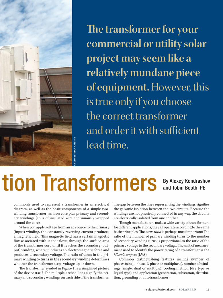
The transformer for your commercial or utility solar project may seem like a relatively mundane piece of equipment. However, this is true only if you choose the correct transformer and order it with sufficient lead time. In this article, we provide a definitive and practical guide that will help you select and specify pad-mounted distribution transformers for commer-cial and utility solar facilities.BY ALEXEY KONDRASHOV AND TOBIN BOOTH, PE
32 Centralized and Decentralized PV Power Plants: Vendor Perspectives
While the size and sophistication of centralized power conditioning systems for utility-scale proj-ects continues to grow, a compelling trend is chal-lenging the centralized “bigger is better” approach. In the last two years, the industry has seen the develop-ment and introduction of a new class of high-capacity string inverters that are well suited for both commer-cial and industrial use and increasingly are showing up in utility-scale PV power plants.BY JOE SCHWARTZ
50 Residential Solar Business Software Platforms
Choosing the right business software platform—based on company business model and strengths—could help smaller residential solar installers remain com-petitive. In this article, we explore how software tools have changed the industry landscape and how smaller solar compa-nies can take advantage of opportunities to streamline and optimize their business practices—advantages that used to be available only to larger national firms.BY PAMELA CARGILL
ContentsF e a t u r e s
March/April 2015 Issue 8.2
18
50
32

The TRIO. Goes anywhere. That’s why it’s everywhere.
The ABB TRIO is a favorite of installers worldwide. Partly, because of scale — the TRIO serves 20KW rooftop mounts just as well as 30MW power stations. Partly, because of flexibility — the TRIO comes with four wiring box options, accommodating the trickiest designs while eliminating the need for expensive extra components. But increasingly, it’s because of the future: The TRIO is a NEMA 4X, smart inverter, compliant with NEC 2014, includes ramp rate and advanced dynamic reactive power controls. So while our TRIO is valuable to installers today, it’s designed to be even more valuable tomorrow. Sign up for the TRIO rebate program at www.abb-solarinverters.com/trio-rebate

4 S O L ARPRO | March/April 2015
D e p a r t m e n t s
FRONT END
6 Contributors Experience + Expertise
8 The Wire Industry Currents
12 QA Quality Assurance
Evaluating Glare from Roof-Mounted PV Arrays
Contents2 March/April 2015 Issue 8.2
f O N T H E C O V E R The San Miguel Power Association (SMPA) Community Solar Farm is a unique installation that was
commissioned in 2012. Located in remote Paradox Valley, Colorado, the project is a collaborative
effort between Clean Energy Collective, Martifer Solar and Sunsense Solar. Sunsense led the design,
engineering and construction of the 1.1 MWdc system that deploys 4,784 Hanwha SolarOne modules
on S:Flex racking. Power conditioning is provided by an AE Solar Energy PowerStation 1000NX that
integrates two AE 500NX-HE inverters and a 1,000 kVA 25 kV/480 V transformer, as well as additional
BOS components. Photo: Courtesy Sunsense Solar
BACK END
64 Projects System Profiles
North Coast Solar, Stony Point Rock Quarry Sunlight Solar Energy, Puffer Residence
67 Advertiser Index
8
Incidentlight Reflected
light
Normal
Angle ofreflectance
Angle ofincidence
a a
12
64

Made in USA
More Options. More Sales. More Solar.Master the art of installing solar on tile with Quick Mount PV’s highly versatile mounting options. Mounting PV on tile has never been easier, stronger, and more waterproof.
(925) 478-8269
Say Yes to Tile
Strongest tile roof mount available. Flashed at both the deck and tile levels for code compliance and superior waterproofing. Works on both curved and flat tile.
Quick Hook®
Now available with multiple height options and designed for use with side-mounted or bottom-mounted rails. Includes preformed flashing for code compliance and superior waterproofing.
Free SampleVisit our website
quickmountpv.com
QBase® Universal Tile

6 S O L A R PR O | March/April 2015
Publisher/Editor Joe Schwartz
Managing Editor Kathryn Houser
Senior Technical Editor/PV Systems David Brearley
Technical Editor/PV Systems Ryan Mayfield
Engineering Editor/PV Systems Blake Gleason, PE
Creative Services Midnight Oil Design
Copy Editors/Proofreaders Kim Saccio-Kent,
Gail Nelson-Bonebrake
Advertising Directors Kim Bowker, Connie Said
Operations Director Scott Russell
Data Manager Doug Puffer
g C O N T A C T U S
SubscriptionsTo apply for a free subscription:
solarprofessional.com/subscribe
Send subscription questions to: [email protected]
To change subscription information:solarprofessional.com/myaccount
Letters to the Editor Email your comments and suggestions to:
Industry PR Send news and equipment releases to:
AdvertisingFor advertising opportunities, visit:
solarprofessional.com/advertise
Western States Sales OfficeConnie Said, Advertising [email protected]: 541.326.5773
Eastern States Sales OfficeKim Bowker, Advertising [email protected]: 541.858.1791
MarketingPromotional opportunities and offers:
SolarPro magazine | PO Box 68 | Ashland, OR 97520 | US
Proud supporter of:
Copyright © 2015 Home Power, Inc. Contents may not be reprinted or otherwise reproduced without written permission. SolarPro is a registered trademark of Home Power, Inc.
While SolarPro magazine strives to publish only safe and accurate content, we assume no
responsibility or liability for the use of this information.
Interior paper is made from 85%–100% recycled material, including 20%–30%
postconsumer waste.
National Electrical Code®, NFPA 70® and NEC® are registered trademarks of the National Fire Protection Association, Quincy, Massachusetts.
®Contributors
Experience + Expertise
Pamela Cargill, principal of Chaolysti,
specializes in process improvement and
operational effectiveness in residential
solar. She developed new programs for
and scaled large national brands such as
Alteris Renewables (now Real Goods Solar)
and Sungevity. Her decade of experience
includes design, installation, project
management and customer expertise.
Roger Colton is an attorney and econo-
mist specializing in regulatory economics
at Fisher, Sheehan & Colton of Belmont,
Massachusetts. As a co-chair of the Bel-
mont Energy Committee and a member
of the Massachusetts Municipal Energy
Group, Colton drafted Belmont’s solar
zoning bylaw and assisted in drafting the
Belmont Light Department solar tariff.
Alexey Kondrashov is a project engineer
at Blue Oak Energy, designing large-scale
solar projects. With practical experience in
the construction industry and an engineer-
ing background, Kondrashov has made
significant contributions to renewable
energy deployment. He holds electrical
engineering degrees from St. Petersburg
Electrotechnical University in Russia.
Joe Schwartz is the CEO of Home
Power. He serves as the publisher and
editor of SolarPro magazine and the
executive editor of Home Power maga-
zine. Schwartz worked as a systems
integrator prior to entering technical
publishing and holds a Limited Renew-
able Energy Technician license in the
state of Oregon.
Tobin Booth, PE, is the founder and CEO
of Blue Oak Energy. With nearly 20 years
of experience delivering solar facilities,
he is a pivotal figure in transitioning the
US energy infrastructure. Booth attended
North Carolina State University and Colo-
rado State University, where he earned a
mechanical engineering degree.

/ Perfect Welding / Solar Energy / Perfect Charging
COMMERCIAL PROJECTS THAT LAST.THE FRONIUS SYMO.
/ 10 – 24 kW. Three Phase SnapINverters for unparalleled ease of installation.
/ Protect your investment in sustainability - with the only truly field serviceable commercial string inverter.
/ Fronius SuperFlex allows for utmost design flexibility in 208/240 and 480/204 AC applications.
/ Complete Solution inside: NEC 2014 compliant, on board WiFi, Modbus, AFCI, String Combiner & DC disconnect.
/ Only string inverter to allow for both a standard wall mount and mounting completely flat on a roof or on a pole.
www.fronius-usa.com • Follow us @FroniusUSASolar on Twitter!
8 S O L A R PR O | March/April 2015
the Wire
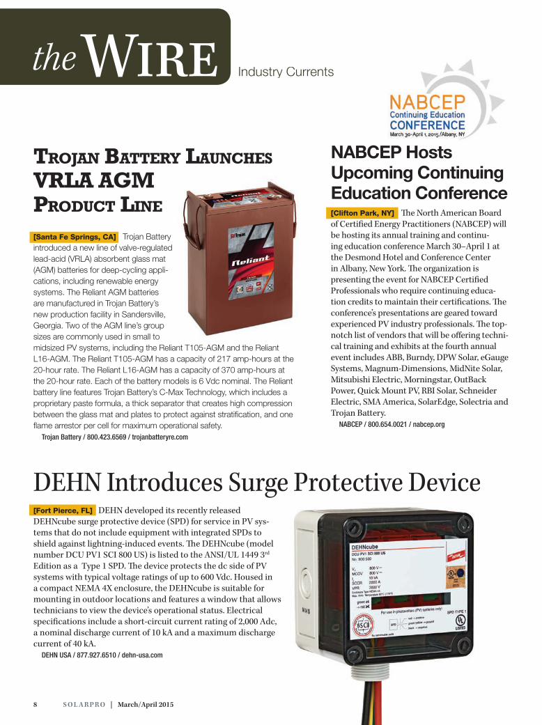
DEHN Introduces Surge Protective Device[Fort Pierce, FL] DEHN developed its recently released DEHNcube surge protective device (SPD) for service in PV sys-tems that do not include equipment with integrated SPDs to shield against lightning-induced events. The DEHNcube (model number DCU PV1 SCI 800 US) is listed to the ANSI/UL 1449 3rd Edition as a Type 1 SPD. The device protects the dc side of PV systems with typical voltage ratings of up to 600 Vdc. Housed in a compact NEMA 4X enclosure, the DEHNcube is suitable for mounting in outdoor locations and features a window that allows technicians to view the device’s operational status. Electrical specifications include a short-circuit current rating of 2,000 Adc, a nominal discharge current of 10 kA and a maximum discharge current of 40 kA.
DEHN USA / 877.927.6510 / dehn-usa.com
Trojan BaTTery Launches VrLa aGM ProducT Line
[Santa Fe Springs, CA] Trojan Battery introduced a new line of valve-regulated lead-acid (VRLA) absorbent glass mat (AGM) batteries for deep-cycling appli-cations, including renewable energy systems. The Reliant AGM batteries are manufactured in Trojan Battery’s new production facility in Sandersville, Georgia. Two of the AGM line’s group sizes are commonly used in small to midsized PV systems, including the Reliant T105-AGM and the Reliant L16-AGM. The Reliant T105-AGM has a capacity of 217 amp-hours at the 20-hour rate. The Reliant L16-AGM has a capacity of 370 amp-hours at the 20-hour rate. Each of the battery models is 6 Vdc nominal. The Reliant battery line features Trojan Battery’s C-Max Technology, which includes a proprietary paste formula, a thick separator that creates high compression between the glass mat and plates to protect against stratification, and one flame arrestor per cell for maximum operational safety.
Trojan Battery / 800.423.6569 / trojanbatteryre.com
NABCEP Hosts Upcoming Continuing Education Conference [Clifton Park, NY] The North American Board of Certified Energy Practitioners (NABCEP) will be hosting its annual training and continu-ing education conference March 30–April 1 at the Desmond Hotel and Conference Center in Albany, New York. The organization is presenting the event for NABCEP Certified Professionals who require continuing educa-tion credits to maintain their certifications. The conference’s presentations are geared toward experienced PV industry professionals. The top-notch list of vendors that will be offering techni-cal training and exhibits at the fourth annual event includes ABB, Burndy, DPW Solar, eGauge Systems, Magnum-Dimensions, MidNite Solar, Mitsubishi Electric, Morningstar, OutBack Power, Quick Mount PV, RBI Solar, Schneider Electric, SMA America, SolarEdge, Solectria and Trojan Battery.
NABCEP / 800.654.0021 / nabcep.org
Industry Currents

Pile PerfectIndustry’s Best Pile Driven Racking
Max-Span™ SystemFewest partsLongest spanFastest install
All Your Commercial & Utility PV Racking NeedsBALLASTED GROUND POST GROUNDCARPORT & ROOF
MADEin USA
212.359.0205
25 year warrantyETL / UL 2703 tested
Wind tunnel tested by industry leader CPPIndependent assessment by Black & Veatch
10 S O L A R PR O | March/April 2015
the Wire
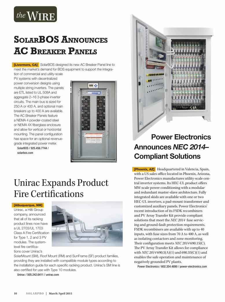
Unirac Expands Product Fire Certifications [Albuquerque, NM]
Unirac, a Hilti Group company, announced that all of its racking product lines now have a UL 2703/UL 1703 Class A Fire Certification for Type 1, 2 and 3 PV modules. The system-level fire certifica-tions cover Unirac’s SolarMount (SM), Roof Mount (RM) and SunFrame (SF) product families, providing they are installed with compatible module types according to the installation guide for each specific racking product. Unirac’s SM line is also certified for use with Type 10 modules.
Unirac / 505.242.6411 / unirac.com
soLarBos announces ac Breaker PaneLs
[Livermore, CA] SolarBOS designed its new AC Breaker Panel line to meet the market’s demand for BOS equipment to support the integra-tion of commercial and utility-scale PV systems with decentralized power conversion designs using multiple string inverters. The panels are ETL listed to UL 508A and aggregate 2–16 3-phase inverter circuits. The main bus is sized for 250 A or 400 A, and optional main breakers up to 400 A are available. The AC Breaker Panels feature a NEMA 4 powder-coated steel or NEMA 4X fiberglass enclosure and allow for vertical or horizontal mounting. The panel configuration has space for an optional revenue-grade integrated power meter.
SolarBOS / 925.456.7744 /
solarbos.com
Power ElectronicsAnnounces NEC 2014–Compliant Solutions
[Phoenix, AZ] Headquartered in Valencia, Spain, with a US sales office located in Phoenix, Arizona, Power Electronics manufactures utility-scale cen-tral inverter systems. Its HEC-UL product offers MW-scale power conditioning with a modular and redundant master-slave architecture. Fully integrated skids are available with one or two HEC-UL inverters, a pad-mount transformer and customized auxiliary panels. Power Electronics’ recent introduction of its FSDK recombiners and PV Array Transfer Kit provide compliant solutions that meet the NEC 2014 fuse servic-ing and ground-fault protection requirements. FSDK recombiners are available with up to 40 inputs, with fuse sizes from 70 A to 400 A, as well as isolating contactors and zone monitoring. Their configuration meets NEC 2014 690.15(C). The PV Array Transfer Kit allows for compliance with NEC 2014 690.5(A)(1) and 690.35(C)(1) and enables the safe operation and maintenance of negatively grounded PV plants.
Power Electronics / 602.354.4890 / power-electronics.com
Introducing Trojan’s Reliant™ AGM with C-Max Technology™, an all-encompassing portfolio of U.S. made, true deep-cycle, non-spillable batteries for a wide range of applications. Take a step in a new direction — Reliant AGM
800.423.6569 / +1 562-236-3000 / trojanbattery.com
There’s a New Direction in AGM
C - M A X
TECHNOLOGY
12 S O L A R PR O | March/April 2015
A s more homeowners choose to install PV systems, jurisdictional
authorities and other stakeholder groups are increasingly scrutinizing the potential impacts of rooftop PV arrays. One recurring concern is that the reflected sunlight associated with roof-mounted PV may adversely affect residential neighborhoods.
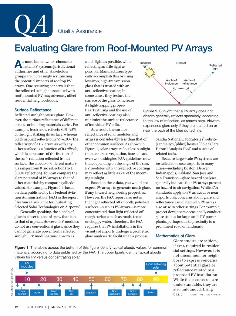
Surface Reflectance Reflected sunlight causes glare. How-ever, the surface reflectance of different objects or building materials varies. For example, fresh snow reflects 80%–95% of the light striking its surface, whereas black asphalt reflects only 5%–10%. The reflectivity of a PV array, as with any other surface, is a function of its albedo, which is a measure of the fraction of the sun’s radiation reflected from a surface. The albedo of different materi-als ranges from 0 (no reflection) to 1 (100% reflection). You can compare the glare potential of PV arrays to that of other materials by comparing albedo values. For example, Figure 1 is based on data published by the Federal Avia-tion Administration (FAA) in the report “Technical Guidance for Evaluating Selected Solar Technologies on Airports.”
Generally speaking, the albedo of glass is closer to that of snow than it is to that of asphalt. However, PV modules do not use conventional glass, since they cannot generate power from reflected sunlight. PV modules must absorb as
much light as possible, while reflecting as little light as possible. Manufacturers typi-cally accomplish this by using low-iron, high-transmission glass that is treated with an anti-reflective coating. In some cases, they texture the surface of the glass to increase its light-trapping proper-ties. Texturing and the use of anti-reflective coatings also minimize the surface reflectance of individual PV cells.
As a result, the surface reflectance of solar modules and arrays is considerably less than that of other common surfaces. As shown in Figure 1, solar arrays reflect less sunlight than concrete, vegetation, bare soil and even wood shingles. FAA guidelines note that, depending on the angle of the sun, PV modules with anti-reflective coatings may reflect as little as 2% of the incom-ing sunlight.
Based on these data, you would not expect PV arrays to generate much glare, if any, toward neighboring properties. However, the FAA report also notes that light reflected off smooth, polished surfaces—such as PV arrays—is more concentrated than light reflected off rough surfaces such as roads, trees or choppy water. Therefore, the FAA requires that PV installations in the vicinity of airports undergo a geometric glare analysis. To facilitate this process,
Sandia National Laboratories’ website (sandia.gov/phlux) hosts a “Solar Glare Hazard Analysis Tool” and a suite of related tools.
Because large-scale PV systems are installed at or near airports in many cities—including Boston, Denver, Indianapolis, Oakland, San Jose and San Francisco—glare hazard analyses generally indicate that PV arrays present no hazard to air navigation. While FAA standards apply to PV arrays at or near airports only, concerns about glare and reflectance associated with PV arrays also arise in other settings. For example, project developers occasionally conduct glare studies for large-scale PV power plants, perhaps due to proximity to a prominent road or landmark.
Mathematics of Glare Glare studies are seldom, if ever, required in residen-tial settings. However, it is not uncommon for neigh-bors to express concerns about potential glare or reflectance related to a proposed PV installation. While these concerns are understandable, they are also unfounded. Using basic
QA Quality Assurance
Evaluating Glare from Roof-Mounted PV Arrays
Co
urt
esy
So
larc
en
tury
10 20 30 40 50 60 70 80 90
PVmodules Concentrating
solar
Blackasphalt Water Wood
shingleBaresoil Vegetation Bare
aluminumWhite
concrete Snow
Figure 1 The labels across the bottom of this figure identify typical albedo values for common materials, according to data published by the FAA. The upper labels identify typical albedo values for PV versus concentrating solar.
Incidentlight Reflected
light
Normal
Angle ofreflectance
Angle ofincidence
a a
Figure 2 Sunlight that a PV array does not absorb generally reflects specularly, according to the law of reflection, as shown here. Viewers experience glare only if they are located on or near the path of the blue dotted line.
C O N T I N U E D O N PA G E 1 4
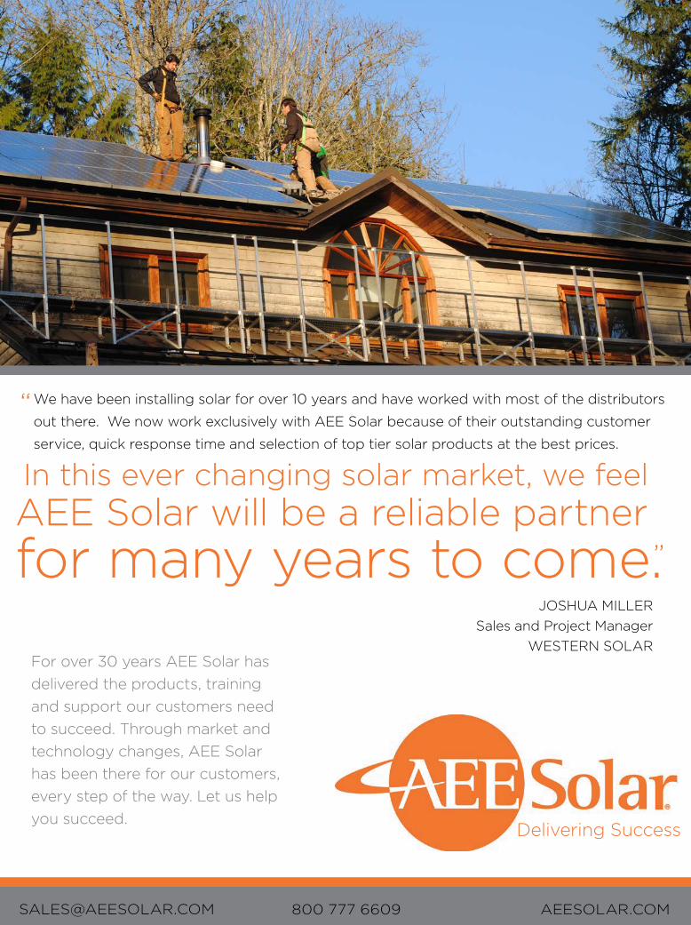
JOSHUA MILLERSales and Project Manager
WESTERN SOLAR
In this ever changing solar market, we feelAEE Solar will be a reliable partnerfor many years to come.
Delivering Success
We have been installing solar for over 10 years and have worked with most of the distributors
out there. We now work exclusively with AEE Solar because of their outstanding customer
service, quick response time and selection of top tier solar products at the best prices.
For over 30 years AEE Solar has delivered the products, training and support our customers need to succeed. Through market and technology changes, AEE Solar has been there for our customers, every step of the way. Let us help you succeed.
AEESOLAR.COM800 777 [email protected]
”
“
2013 Creative Western Solar.indd 1 4/30/2014 1:57:08 PM
14 S O L A R PR O | March/April 2015
QA
physics, math and trigonometry, you can show that even if a PV array reflects some sunlight, it is highly unlikely that a third-party observer will see glare effects, especially if the potential viewer is located on an abut-ting property. Sunlight reflected off a residential roof-mounted PV array is most likely to travel skyward, up and over adjacent structures.
Law of reflection. Sunlight striking a smooth surface behaves in a predictable manner according to the law of reflec-tion. As illustrated in Figure 2 (p. 12), the law of reflection states that when sunlight strikes a flat surface, the angle
5am
6am
7am
8am
9am
10am
11am
12pm
1pm
2pm
3pm
4pm
5pm
6pm
7pm
0º -30º -60º -90º -120º30º60º90º120ºSouth WestEast
Altit
ude
angl
e
0º
30º
20º
10º
40º
50º
60º
70ºSummer solstice
May/ Jul 21
Apr/ Aug 20
Equinox
Feb/ Oct 21
Jan/ Nov 21Wintersolstice
Azimuth angle
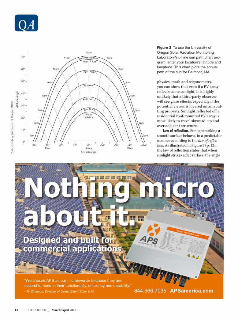
Figure 3 To use the University of Oregon Solar Radiation Monitoring Laboratory’s online sun path chart pro-gram, enter your location’s latitude and longitude. This chart plots the annual path of the sun for Belmont, MA.
Da
ta c
ou
rte
sy U
niv
ers
ity
of
Ore
go
n S
RM
L
“We choose APS as our microinverter because they are second to none in their functionality, efficiency and durability.”- Ty Simpson, Director of Sales, Bland Solar & Air APSamerica.com 844.666.7035
Nothing microabout it.Designed and built for commercial applications
solarprofessional.com | S O L A R PR O 15
of incidence equals the angle of reflec-tance, as measured on either side of the line that is normal (perpendicular) to the reflecting surface. In effect, the direc-tion of the reflected light mirrors that of the incoming light.
Location of sun. For viewers to experi-ence glare from the reflected sunlight in Figure 2, they would have to be located in or near the direct path of reflection. The location of the sun is a primary variable in any glare hazard analysis. The altitude angle of the sun determines the altitude angle of the reflection, accord-ing to the law of reflection, as measured off a line normal to the surface of the array. Further, the solar azimuth angle determines the plane along which the reflected light travels.
One of the simplest ways to iden-tify the location of the sun for a glare hazard analysis is to use the University of Oregon Solar Radiation Monitoring
Laboratory (SRML) sun path chart program (solardat.uoregon.edu/SoftwareTools.html). You can generate an annual sun path chart for a specific location by simply entering a zip code or the site latitude and longitude. Figure 3 is a sample sun path chart generated for Belmont, Massachusetts.
Angle of reflectance. The altitude angle of the sun varies according to the time of day and year. The lowest altitude angle occurs daily at sunrise and sunset; the highest altitude angle occurs at solar noon on the summer solstice. A glare hazard analysis for a full year typically includes altitude angle calculations for reflected sun-light at representative times of the day (sunrise, solar noon, sunset) and year (spring equinox, summer solstice, fall equinox, winter solstice). Since most residential roof-mounted PV arrays are installed at a tilt angle rather than
horizontally, you must account for this tilt angle in your calculations. One way to do this is to use basic trigonometry.
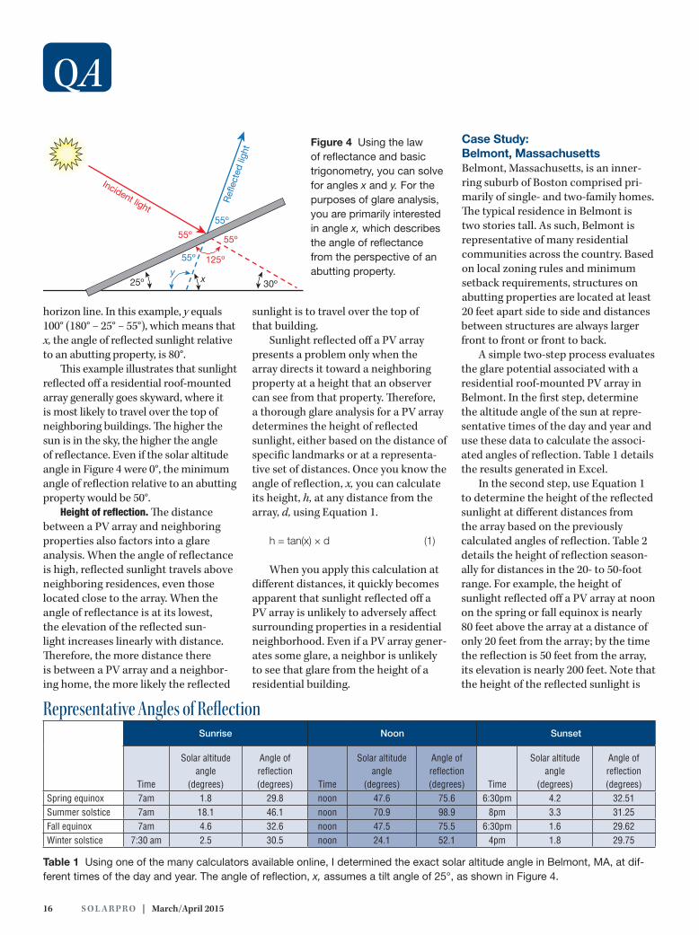
Figure 4 (p. 16), for example, assumes an array tilt angle of 25° and a solar alti-tude angle of 30°. Because all the angles in a triangle add up to 180°, we know that the angle between the incident light and the back of the module equals 125° (180° − 25° − 30°). Since the angles that make up a straight line also equal 180°, we know that the angle between the incident light and the front of the PV array equals 55° (180° − 125°). The law of reflection dictates that the reflected light and the plane of the array mirror this 55° angle. Because opposite angles resulting from intersecting straight lines are congruent, two opposite angles on the backside of the PV array both equal 55°. You now have all the information needed to solve for x, which is the angle of the reflected light as measured off the
Measure and Maximize your
O&M is critical to the ROI of your PV projects, and so is your choice of curve tracer
Choose the Solmetric PV Analyzer I-V Curve Tracer:
• Highest accuracy and throughput • Largest display with best array
troubleshooting features • Database of 50,000 PV modules
• 1000V, 20A and 30A models • 300ft wireless sensor range
www.solmetric.com
16 S O L A R PR O | March/April 2015
horizon line. In this example, y equals 100° (180° − 25° − 55°), which means that x, the angle of reflected sunlight relative to an abutting property, is 80°.
This example illustrates that sunlight reflected off a residential roof-mounted array generally goes skyward, where it is most likely to travel over the top of neighboring buildings. The higher the sun is in the sky, the higher the angle of reflectance. Even if the solar altitude angle in Figure 4 were 0°, the minimum angle of reflection relative to an abutting property would be 50°.
Height of reflection. The distance between a PV array and neighboring properties also factors into a glare analysis. When the angle of reflectance is high, reflected sunlight travels above neighboring residences, even those located close to the array. When the angle of reflectance is at its lowest, the elevation of the reflected sun-light increases linearly with distance. Therefore, the more distance there is between a PV array and a neighbor-ing home, the more likely the reflected
sunlight is to travel over the top of that building.
Sunlight reflected off a PV array presents a problem only when the array directs it toward a neighboring property at a height that an observer can see from that property. Therefore, a thorough glare analysis for a PV array determines the height of reflected sunlight, either based on the distance of specific landmarks or at a representa-tive set of distances. Once you know the angle of reflection, x, you can calculate its height, h, at any distance from the array, d, using Equation 1.
h = tan(x) × d (1)
When you apply this calculation at different distances, it quickly becomes apparent that sunlight reflected off a PV array is unlikely to adversely affect surrounding properties in a residential neighborhood. Even if a PV array gener-ates some glare, a neighbor is unlikely to see that glare from the height of a residential building.
Case Study: Belmont, Massachusetts Belmont, Massachusetts, is an inner-ring suburb of Boston comprised pri-marily of single- and two-family homes. The typical residence in Belmont is two stories tall. As such, Belmont is representative of many residential communities across the country. Based on local zoning rules and minimum setback requirements, structures on abutting properties are located at least 20 feet apart side to side and distances between structures are always larger front to front or front to back.
A simple two-step process evaluates the glare potential associated with a residential roof-mounted PV array in Belmont. In the first step, determine the altitude angle of the sun at repre-sentative times of the day and year and use these data to calculate the associ-ated angles of reflection. Table 1 details the results generated in Excel.
In the second step, use Equation 1 to determine the height of the reflected sunlight at different distances from the array based on the previously calculated angles of reflection. Table 2 details the height of reflection season-ally for distances in the 20- to 50-foot range. For example, the height of sunlight reflected off a PV array at noon on the spring or fall equinox is nearly 80 feet above the array at a distance of only 20 feet from the array; by the time the reflection is 50 feet from the array, its elevation is nearly 200 feet. Note that the height of the reflected sunlight is
QA
Sunrise Noon Sunset
Time
Solar altitude angle
(degrees)
Angle of reflection (degrees) Time
Solar altitude angle
(degrees)
Angle of reflection (degrees) Time
Solar altitude angle
(degrees)
Angle of reflection (degrees)
Spring equinox 7am 1.8 29.8 noon 47.6 75.6 6:30pm 4.2 32.51Summer solstice 7am 18.1 46.1 noon 70.9 98.9 8pm 3.3 31.25Fall equinox 7am 4.6 32.6 noon 47.5 75.5 6:30pm 1.6 29.62Winter solstice 7:30 am 2.5 30.5 noon 24.1 52.1 4pm 1.8 29.75
Table 1 Using one of the many calculators available online, I determined the exact solar altitude angle in Belmont, MA, at dif-ferent times of the day and year. The angle of reflection, x, assumes a tilt angle of 25°, as shown in Figure 4.
Representative Angles of Reflection
30º
Incident light
25º
55ºRe
flect
ed lig
ht
y125º
55º
55º
55º
x
Figure 4 Using the law of reflectance and basic trigonometry, you can solve for angles x and y. For the purposes of glare analysis, you are primarily interested in angle x, which describes the angle of reflectance from the perspective of an abutting property.

solarprofessional.com | S O L A R PR O 17
not relative to ground level but origi-nates at the installed height of the roof-mounted array.
These data clearly indicate that glare from roof-mounted PV arrays is unlikely to pose a problem for neigh-bors when the sun is highest in the sky. Based on the typical distances between residences in Belmont,
Massachusetts, reflected sunlight is most likely to travel over structures on abutting properties. While this simple analysis may not rule out the potential for glare at sunrise or sunset, you can perform similar analyses that take azi-muth angles into account. Generally speaking, if a PV array is facing south, incident sunlight at sunrise and sunset
arriving from the east or the west does not directly strike the surface of a residential roof-mounted array. By the time sunlight does strike the array directly, its angle of incidence is high enough to preclude the visibility of any glare to neighbors.
—Roger Colton / Fisher Sheehan & Colton / Belmont, MA / fsconline.com
Table 2 This table shows how the height of reflected sunlight changes based on solar altitude angle and the distance from the array. Note that these elevations are relative to the installed height of the roof-mounted array rather than to ground level.
Distance from PV array
Seasonal height of reflection (feet) by distance from PV array (feet) and time of daySpring equinox Summer solstice Fall equinox Winter solstice
(Feet) Sunrise Noon Sunset Sunrise Noon Sunset Sunrise Noon Sunset Sunrise Noon Sunset20 12 78 13 21 128 12 13 77 11 12 26 1125 14 98 16 26 160 15 16 97 14 15 32 1430 17 117 19 31 192 18 19 116 17 18 39 1735 20 136 22 36 224 21 22 135 20 21 45 2040 23 156 26 42 257 24 26 155 23 24 51 2345 26 176 29 47 289 27 29 174 26 26 58 2650 29 195 32 52 321 30 32 193 28 30 64 29
Elevation of Reflection by Distance
Revolutionary cable pathways drastically cut installation times to lower construction costs!
www.snaketray.com800.308.6788
Made in the USASnake Tray® products are patent protected.
Visit our website for speci c patent information.
Snake Tray® Cable Management for Solar Installations
Snake Tray products have built-in mounting hardware and nest together for cost-effective shipping and handling.
NEW ICE GUARD FOR SOLAR PANELS PREVENTS INJURIES DUE TO FALLING ICE
NewProduct

18 S O L A R PR O | March/April 2015
The relative simplicity of transformers belies their importance. Transformers are ubiquitous in ac elec-trical systems, used in appliances, inverters, mea-suring devices, construction tools and all manner of
electronic devices. Transformers are also a key component for electrical power transmission and distribution. One of the power industry’s guiding principles is that transmitting power at higher voltages is more efficient. Therefore, engineers use transformers at power generation facilities—including PV power plants—to step up to high-voltage levels for long- distance transmission. Closer to towns and cities, substa-tion and distribution transformers step voltage levels down at multiple stages and locations to deliver electricity to com-mercial, industrial and residential loads.
In this article, we cover the fundamentals of trans-former construction and operation. We discuss the gen-eral use of distribution and substation transformers in
commercial and utility solar applications. We consider important transformer ratings and features. Finally, we summarize factory and field tests. If you do not take these considerations into account, the humble transformer can trip up your whole project. Our goal is to provide a defini-tive and practical guide that will help you select and spec-ify pad-mounted distribution transformers for commercial and utility solar facilities.
Transformer FundamentalsA transformer is a static electrical device used to transfer elec-tric power by electromagnetic induction from one ac circuit to another—at the same frequency, but with different voltage and current values—without a direct electrical connection between the two circuits. Figure 1 (p. 20) shows the symbol
Distribution and Substa tion Transformers
solarprofessional.com | S O L A R PR O 19
Co
urt
es
y S
MA
Am
eri
ca
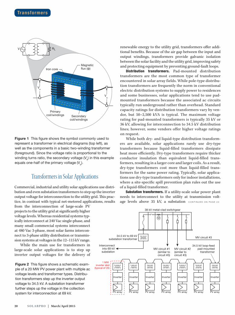
commonly used to represent a transformer in an electrical diagram, as well as the basic components of a simple two-winding transformer: an iron core plus primary and second-ary windings (coils of insulated wire continuously wrapped around the core).
When you apply voltage from an ac source to the primary (input) winding, the constantly reversing current produces a magnetic field. This magnetic field has a certain magnetic flux associated with it that flows through the surface area of the transformer core until it reaches the secondary (out-put) winding, where it induces an electromagnetic force and produces a secondary voltage. The ratio of turns in the pri-mary winding to turns in the secondary winding determines whether the transformer steps voltage up or down.
The transformer symbol in Figure 1 is a simplified picture of the device itself. The multiple-arched lines signify the pri-mary and secondary windings on each side of the transformer.
The gap between the lines representing the windings signifies the galvanic isolation between the two circuits. Because the windings are not physically connected in any way, the circuits are electrically isolated from one another.
Though manufacturers make a wide variety of transformers for different applications, they all operate according to the same basic principles. The turns ratio is perhaps most important: The ratio of the number of primary winding turns to the number of secondary winding turns is proportional to the ratio of the primary voltage to the secondary voltage. The unit of measure-ment used to identify the power rating of a transformer is the kilovolt-ampere (kVA).
Common distinguishing features include number of phases (single-phase, 3-phase or multiphase), number of wind-ings (single, dual or multiple), cooling method (dry type or liquid type) and application (generation, substation, distribu-tion, grounding or autotransformer).
By Alexey Kondrashov and Tobin Booth, PE
The transformer for your commercial or utility solar project may seem like a relatively mundane piece of equipment. However, this is true only if you choose the correct transformer and order it with sufficient lead time.
Distribution and Substa tion Transformers
20 S O L A R PR O | March/April 2015
Transformers in Solar ApplicationsCommercial, industrial and utility solar applications use distri-bution and even substation transformers to step up the inverter output voltage for interconnection to the utility grid. This prac-tice, in contrast with typical net-metered applications, results from the interconnection of large-scale PV projects to the utility grid at significantly higher voltage levels. Whereas residential systems typ-ically interconnect at 240 Vac single-phase, and many small commercial systems interconnect at 480 Vac 3-phase, most solar farms intercon-nect to 3-phase utility distribution or transmis-sion systems at voltages in the 12–115 kV range.
While the main use for transformers in large-scale solar applications is to step up inverter output voltages for the delivery of
renewable energy to the utility grid, transformers offer addi-tional benefits. Because of the air gap between the input and output windings, transformers provide galvanic isolation between the solar facility and the utility grid, improving safety and protecting equipment by preventing ground-fault loops.
Distribution transformers. Pad-mounted distribution transformers are the most common type of transformer encountered in solar array fields. While pole-type distribu-tion transformers are frequently the norm in conventional electric distribution systems to supply power to residences and some businesses, solar applications tend to use pad-mounted transformers because the associated ac circuits typically run underground rather than overhead. Standard capacity ratings for distribution transformers vary by ven-dor, but 50–2,500 kVA is typical. The maximum voltage rating for pad-mounted transformers is typically 35 kV or 36 kV, allowing for interconnection to 34.5 kV distribution lines; however, some vendors offer higher voltage ratings on request.
While both dry- and liquid-type distribution transform-ers are available, solar applications rarely use dry-type transformers because liquid-filled transformers dissipate heat more efficiently. Dry-type transformers require thicker conductor insulation than equivalent liquid-filled trans-formers, resulting in a larger core and larger coils. As a result, dry-type transformers cost more than liquid-filled trans-formers for the same power rating. Typically, solar applica-tions use dry-type transformers only for indoor installations, where a site-specific spill prevention plan rules out the use of a liquid-filled transformer.
Substation transformers. If a utility-scale solar power plant needs to interconnect to the utility at transmission volt-age levels above 35 kV, a substation C O N T I N U E D O N PA G E 2 2
Transformers
Primarycoil/windings Secondary
coil/windings
V RL
VP
VS
Iron coreMagneticflux (φ)
Figure 1 This figure shows the symbol commonly used to represent a transformer in electrical diagrams (top left), as well as the components in a basic two-winding transformer (foreground). Since the voltage ratio is proportional to the winding turns ratio, the secondary voltage (Vs) in this example equals one-half of the primary voltage (Vp).
M
38 kV metal-clad switchgear
Inverter
PV array
Inverter
PV array
Inverter
PV array
Inverter
PV array
Inverter
PV array
Inverter
PV array
Interconnectinto 69 kVsubstation
34.5 kV loop-feedpad-mounted
transformer
Inverter
PV array
MV circuit #3
MV circuit #1(similar tocircuit #3)
MV circuit #2(similar tocircuit #3)
34.5 kV to 69 kVsubstation transformer
1 MW inverter skid
(typical of 20)Figure 2 This figure shows a schematic exam-ple of a 20 MW PV power plant with multiple ac voltage levels and transformer types. Distribu-tion transformers step up the inverter output voltage to 34.5 kV. A substation transformer further steps up the voltage in the collection system for interconnection at 69 kV.

www.solarbos.com [email protected] (925) 456-7744
Connect with us!
SolarBOS is now shipping pre-fabricated wire harnesses from our Grand Rapids, Michigan, facility, using industry standard PV wire and connectors. Made to order according to your specifications.
Yes, we do this now too.
Did you know nearly 25% of all solar electricity generated in North America flows through a SolarBOS product? Why not put our expertise to work for you? Call us for a quote for your next project.

22 S O L A R PR O | March/April 2015
transformer must step up the voltage in the plant’s medium-voltage collection system to the appropriate interconnec-tion voltage. Substation transformers normally use the same cooling fluids as distribution transformers, and they have mul-tiple kVA ratings based on the cooling class. Standard name-plate power ratings for substation transformers range from 2,500 kVA to more than 100 megavolt-amperes (MVA).
Though similar to distribution transformers, substation transformers are larger, and they have more complex controls and higher insulation levels to accommodate higher volt-ages. Cable terminations for substation transformers typically consist of busway conductor systems in free air. The unique nature of these terminations, connection methods and struc-tural support systems can make substation transformers seem intimidating. In reality, the same fundamental trans-former concepts apply.
Transformer SpecificationsManufacturers typically build transformers for solar applica-tions to order. This is because vendors offer many options—in terms of materials, configurations and accessories—within the same product line. The product is highly customizable, so delivery lead times for transformers are generally longer than for PV modules or inverters. That makes forethought essential when ordering distribution or substation transformers. For example, a 12-week lead time is typical for distribution trans-formers in the 0.75–2.5 kVA range. However, that lead time can extend to 16 weeks at certain times of the year or in the event of a factory backlog. If you do not wish to incur expedite fees, you need to plan ahead.
When specifying distribution and substation transformers for solar applications, pay particular attention to device ratings and optional features.
IMPORTANT DEVICE RATINGSImportant transformer ratings to consider relate to voltage, winding connections, basic impulse level, impedance, effi-ciency, winding material, temperature rise, insulation class, cooling, seismic resistance and altitude deratings.
Voltage. It is critical to specify the correct nominal voltage levels for distribution and substation transformers. As illus-trated in Figure 2 (p. 20), inverter selection and interconnec-tion voltage, as well as the voltage used in the medium-voltage collection system if this differs from the interconnection voltage, determine voltage levels. (For more information on medium-voltage ac collection systems in PV power plants, see “Basics of Medium-Voltage Wiring,” SolarPro magazine, December/January 2013.)
In the example shown in Figure 2, inverter selection deter-mines the voltage level on the low-voltage side of the distri-bution transformers, which will likely be in the 300–700 Vac
range. Meanwhile, the collection system voltage is 34.5 kV, the maximum standard voltage level for distribution transform-ers. This collection system voltage determines not only the voltage level on the high-voltage side of the distribution trans-formers, but also the nominal voltage level on the low-voltage side of the substation transformer. The utility-interconnection voltage determines the voltage level on the high-voltage side of the substation transformer.
Winding connections. In addition to specifying nominal voltage levels, you must also specify the primary and second-ary winding connections in 3-phase applications. The stan-dard winding connection options on both the primary and secondary sides of the transformer are delta, ungrounded wye and grounded wye.
On the one hand, inverter selection normally governs low-voltage windings. Therefore, it is important to ensure that spec-ified low-voltage winding connections conform to the inverter manufacturer’s requirements. This is especially true when you are connecting multiple inverters to a single transformer, as you cannot connect some inverters in parallel on the second-ary side of a transformer without providing galvanic isolation between the inverters. On the other hand, utility interconnec-tion standards typically govern the high-voltage winding con-nections on the primary side of the transformer, as well as the required protection scheme. Note that utility requirements apply to the primary circuit only if this circuit is interconnected with utility. In other words, if there is a substation, utility stan-dards apply to the primary circuit of the substation transformer and not to the collector system transformers.
The most common 3-phase distribution configuration for transformers in solar applications is the delta-to-wye configu-ration, shown in Figure 3, with the wye
Transformers
InverterUtility
X1
X2
X3
H1
H2
H3
Figure 3 The most common distribution transformer winding configuration in solar applications is the delta-to-wye with wye grounded or ungrounded.
C O N T I N U E D O N PA G E 2 4

YOU WANT A SPRING IN YOUR STEP,NOT IN YOUR POWER
PT-100 Charge ControllerThe PT-100 is a Maximum Power Point Tracking Charge Controller designed to maximize energy harvest from your PV array and improve battery life. Optimally charging batteries, providing electronic protection, and extinguishing series arcs with an integrated PV arc-fault circuit interrupter, the power you see is smooth. The PT-100 can support a PV array of up to 6600 watts and is compatible with 12, 24, or 48 volt systems.
ACLD-40 Load Diversion ControllerThe ACLD-40 monitors the battery voltage of a battery bank and connects to an AC diversion load to avoid overcharging. You don’t need hard-to-find DC loads with the ACLD; and with built-in Pulse Width Modulation, your chosen AC appliances will run without spikes in power. The ACLD-40 controls up to 4000 watts of excess power and works with 12, 24, or 48 volt systems.
To learn more about Magnum-Dimensions products, visit www.magnumenergy.com
The World Depends on Sensors and Controls
PROTECT YOUR BATTERIES AND MAXIMIZE ENERGY HARVEST WITH TWO NEW MAGNUM-DIMENSIONS PRODUCTS FROM SENSATA
PT-100 & ACLD-40 NOW SHIPPING!
24 S O L A R PR O | March/April 2015
grounded or ungrounded. This configuration allows for an independently derived neutral on the wye-connected second-ary winding, which not only is essential for safety purposes but can also provide multiple voltages at the inverter pad without requiring additional transformers. The delta-connected pri-mary winding provides a reliable configuration for the utility, because it allows harmonic currents to circulate within the transformer. This prevents harmonics from flowing into the electrical distribution system.
Substation transformers usually use the grounded wye–to–grounded wye configuration, shown in Figure 4. However, substation transformers are multiwinding transformers that also have a tertiary delta winding. This delta winding pre-vents harmonics from circulating in the electrical trans-mission system and stabilizes the neutral point when loads become unbalanced.
Basic impulse level (BIL). Product safety standards require that manufacturers subject medium-voltage trans-formers to a series of impulse tests, which characterize the level of momentary overvoltage that the transformer insu-lation can withstand without damage or failure. Manufac-turers assign the transformer a BIL rating based on these test results. It is important to specify transformers with the
appropriate BIL rating to ensure that the electrical system can withstand lightning strikes or other electromagnetic impulses. Table 1 (p. 26) provides examples of standard and enhanced BIL ratings for distribution transformers based on voltage class.
Impedance. Electrical impedance, symbolized by Z, char-acterizes opposition to alternating current that accounts for both resistance and reactance in the circuit. As it pertains to transformers, impedance represents the amount of potential energy you must apply to the transformer before you can put it to work. The higher the impedance of the transformer, the more potential energy is necessary. Calculations typically rep-resent transformer impedance as %Z, a value that electrical engineers can easily factor into a variety of applications. How-ever, you can also think of transformer impedance as the volt-age drop across the transformer at full load.
Technicians determine transformer impedance by short-circuiting the secondary winding and applying an adjustable voltage to the primary winding. Starting at 0 V, they slowly increase the primary voltage until they measure full-load current in the secondary winding. They then calculate trans-former impedance by comparing applied voltage to nominal primary voltage. For example, if a technician needs to apply
Transformers
OutBack Power | Masters of the Off-Grid™, First Choice for the New Grid. | 1 (360) 435.6030 | www.outbackpower.com
The Only Way You Lose is By Using Somebody Else’s Batteries
From chemistry to casting, OutBack EnergyCell batteries are known for superiority. Now with OutBack’s OnSite Direct program, it’s easier than ever to specify them into your next system.
On selected battery models, shipping is always half price with OnSite Direct. With fresh batteries guaranteed to ship within fi ve business days of your order’s con fi rmation and credit approval—or the shipping cost is on OutBack. Contact your local distributor or OutBack Power for more information and pricing.
EnergyCell RE
� Top Terminal Design � O� -Grid Deep Cycle Applications
EnergyCell RE
� Front Terminal Design � O� -Grid Deep Cycle Applications
EnergyCell GH
� Front Terminal Design � Grid/Hybrid and Backup Applications
EnergyCell RE
� Front Terminal Design � 2V High Capacity Deep Cycle
*OutBack EnergyCell GH batteries have up to twice the capacity of traditional 12V Group 31 VRLA batteries in PV applications.
Up to Twice the Performance for Half the Shipping Cost.*

solarprofessional.com | S O L A R PR O 25
600 V to a 12,000 V primary winding to create full-load cur-rent in the secondary winding, then the transformer imped-ance is 5% (600 ÷ 12,000).
Transformers under 50 kVA have impedances of less than 2% because they contain less copper and steel to energize. For 750 kVA–2,500 kVA transformers, the standard nominal impedance value is 5.75%. The IEEE standards permit a toler-ance of ±7.5% for targeted impedance values in two-winding transformers and ±10% in multiwinding transformers. Manu-facturers build high-efficiency transformers to higher design
standards to reduce internal impedance and thus produce lower impedance values. While impedance values for conven-tional substation transformers are typically in the 7%–10% range, you can order these products with special impedance values or desired losses.
Efficiency. Transformer efficiency is a measure of output power relative to input power expressed as a percentage. It tends to increase with transformer capacity. For example, 3-phase distribution transformers in the 75 kVA–1,000 kVA range are 98%–99% efficient, as required by federal law and
Pa
tric
k B
yrd
Figure 4 Substation transformers, like the one in the photo on the left, are typically grounded wye–to–grounded wye trans-formers with a tertiary delta winding, as shown in the diagram on the right.
Expanded Facility
Expanded Capabilities
181,760 square feet of brand new space in Phoenix, AZ
602.352.2700 [email protected] www.omcosolar.com
Roll Forming Stamping Custom Assembly Fastener Insertion

26 S O L A R PR O | March/April 2015
associated standards established by the National Electrical Manu-facturers Association (NEMA). However, general purpose transformers in the 0.05 kVa– 1.5 kVA range are typically 85–95% efficient. Because inter-nal transformer eddy current and hysteresis losses are con-stant at all load levels, they can cause a significant percentage of loss at lower load levels, especially for small transform-ers. Designing and manufacturing high-efficiency transform-ers—as compared to general-purpose transformers—requires a larger core with more highly processed silicon steel and larger-diameter conductors for the windings, all of which increases costs. Unless you specify more-stringent require-ments, distribution transformer vendors typically design and manufacture products to meet minimum efficiency standards established by the Department of Energy.
Winding material. Manufacturers offer distribution and substation transformers with copper or aluminum windings. Copper offers better electrical conductivity by volume than aluminum, while aluminum offers better electrical conduc-tivity by mass than copper. Given the same capacity, a distri-bution transformer with copper windings is typically more compact than one with aluminum windings; however, the lat-ter may weigh less than the former. The biggest difference is that transformers with copper windings cost more than those with aluminum windings.
Temperature rise. During operation, efficiency losses result in waste heat, which causes the transformer to oper-ate at temperatures higher than those in the environment. Transformer temperature rise provides a measure of the thermal impacts associated with efficiency losses. This rise is technically defined as the average temperature rise of the windings as compared to the ambient temperature, when the transformer is loaded at its nominal rating.
In practice, however, standard limits based on a maximum ambient temperature of 40°C characterize transformer tem-perature rise. The standard temperature-rise values for liquid-filled transformers are 55°C and 65°C; the standard values for dry-type transformers are 80°C, 115°C and 150°C. If a techni-cian installs a liquid-filled transformer with a temperature rise of 65°C in a 40°C environment and loads it at its nameplate rating, the average temperature of its windings should not exceed 105°C. Transformers used at PV projects experience more thermal cycling than a typical utility distribution trans-former. A solar project transformer starts cold in the morning and reaches its peak temperature midday during peak ambient and peak energy periods. Then it cools back down and starts the cycle over again. Special consideration needs to be given
when selecting a solar project transformer to ensure that the cooling system can handle the temperature swings. A watchful O&M team is also important to carefully monitor and reset the pressure system in some geo-graphic locations.
Generally speaking, highly efficient transformers have lower temperature-rise values than less efficient transformers, because efficient transformers generate less waste heat. However, temperature rise
is also a function of how quickly the transformer removes heat at full load. At partial load levels, transformers with a low temperature rise are not always more efficient than those with a high temperature rise.
Insulation class. As illustrated in Table 2, a transformer’s insulation class correlates to its temperature-rise value. Manufacturers generally accomplish electrical isolation in the transformer with enamel-coated wires and insulating material between the winding layers, and they vary materials and thicknesses to achieve different insulation-class ratings. Once they have insulated the transformer winding, they typi-cally impregnate the coils with a varnish to minimize the pos-sibility of moisture intrusion, reduce sound levels, increase mechanical strength and improve heat transfer, and they then mount the transformer winding in a protective enclosure.
Voltage class
(kV)
Standard BIL
(kV)
Optional BIL
(kV)
2.4 45 60
5 60 75
8.3 75 95
15 95 110
25 125 150
35 150 200
Basic Impulse Level (BIL) Ratings
Table 1 Standard and optional BIL ratings vary by voltage class and vendor.
NEMA class
designation
Max. operating temperature
allowed (°C)
Allowable temperature
rise at full load (°C)
Insulating material
A 105 60
Organic materials such as cotton, silk,
paper and some synthetic fibers
B 130 80Inorganic materials such as mica and
glass fibers
F 155 105
Same as Class B but with adhesive binders
stable at the higher temperature
H 180 125
Same as Class B but with silicone elastomers and
inorganic materials with high-temperature
binders
Table 2 The insulation within a transformer is rated accord-ing to standard NEMA classifications, which determine the maximum operating temperature and the allowable tempera-ture rise.
NEMA Insulation Classes for Transformers
Transformers

solarprofessional.com | S O L A R PR O 27
Cooling. Dry-type transformers are self-cooled and rely on passive methods—conduction, convection and radia-tion—to transfer heat from the transformer to the environ-ment. For example, you might use small air-cooled dry-type transformers to provide station power at the inverter pad. Otherwise, liquid-type transformers are more common in solar applications.
Steel enclosures filled with a nonconductive dielectric fluid, which insulates the internal components and helps keep them cool, protect liquid-type transformers. The heat that the windings generate transfers to the dielectric fluid, which circulates via natural convection. The heat then dis-sipates into the environment via the transformer’s oil cooler, which is an external heat exchanger or radiator. This is a rather elegant and energy-efficient cooling method.
As shown in Table 3 (p. 28), the industry classifies liquid- filled transformer cooling according to internal cooling medium, internal cooling mechanism, external cooling medium and external circulation method. For example, pad-mounted distribution transformers have a cooling classification of ONAN: O indicates that the cooling medium in contact with the windings is an oil with a flash point of 300°C or less; the first N indicates that the oil circulates via
natural convection; A indicates that the external cooling medium is air; the second N indicates that the air circulates via natural convection.
Substation transformers of 10 MVA and larger typically have multiple capacity ratings, such as 12/16/20 MVA, which correspond to different cooling classes, such as ONAN/ONAF/OFAF. In this example, the lowest rating, 12 MVA, represents the self-cooled transformer capacity and has the ONAN cool-ing class rating. The next one, 16 MVA, is the capacity of the transformer when it uses fans to force air through the oil cooler radiators; this rating has the ONAF cooling class rating. The highest rating, 20 MVA, is the capacity of the transformer with both internal coolant circulating pumps and external fans, and it has the OFAF cooling class rating. Each cooling level typically adds approximately 25% more capacity.
Dielectric fluids can be either mineral oil or less- flammable vegetable-based oils, such as Envirotemp FR3 and BIOTEMP. Transformer products designed for solar applications often use the latter because they are derived from a renewable resource and are biodegradable.
Seismic resistance. The 2009 and 2012 editions of the International Building Code contain specific seismic resis-tance requirements for transformers at certain facilities.

28 S O L A R PR O | March/April 2015
Co
urt
es
y E
ato
n
Internal External
Cooling medium Circulation mechanism Cooling medium Circulation mechanism
OLiquid with flash
point <300°CN
Natural convection through cooling equipment and windings
A air NNatural
convection
KLiquid with flash
point >300°CF
Forced circulation through cooling equipment, natural convention in windings
W water FForced circulation (fans or pumps)
LLiquid with no
measurable flash point
DForced circulation through cooling equipment,
directed flow in main windings
Transformer Cooling Classification
Table 3 Liquid-filled transformer cooling is classified according to a four-letter system. The first two letters identify the internal cooling medium and circulation mechanism; the last two letters identify the external cooling medium and circulation mechanism.
Installations at health care facilities, emergency response locations (such as fire and police stations) and critical gov-ernment facilities frequently must have seismic certifica-tion. If you are installing a transformer at one of these types of facilities, check to see if seismic requirements apply.
Altitude deratings. Because the air is less dense at higher altitudes, the effectiveness of the cooling system and the dielectric strength of the transformer decrease at higher elevations. Therefore, you must either derate transformers installed above 3,300 feet or specifically design them for the
location. The product safety standard that applies to liquid-filled distribution and substation transformers requires that you derate transformer capacity by 0.3% for every 330 feet increase in elevation above 3,300 feet.
FEATURES AND OPTIONSImportant transformer features and options to consider relate to dead- versus live-front construction, radial- versus loop-feed configuration, overcurrent protection, overvoltage protection, switches and gauges.
Bay-O-Netfusing
Load-break switch
Dripshield
High-voltage bushing
Sill(suitable for
skidding, rolling and jacking) Parking
stand
5-positiontap changer
Ground pad andstrap for X0
Liquid-levelgauge
Nameplate (laser-scribed anodized aluminum)
Low-voltage bushing support
Low-voltage bushing (low-voltage molded epoxy bushings with NEMA spades)
Removablecabinet walls
Figure 5 This fig-ure shows the basic anatomy of a 3-phase pad-mounted distribu-tion transformer. The high-voltage compart-ment features dead-front bushings in a loop-feed configuration.
Transformers
solarprofessional.com | S O L A R PR O 29
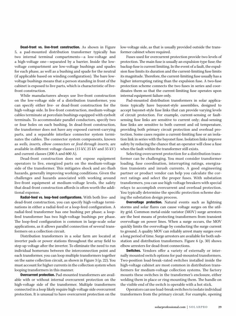
Dead-front vs. live-front construction. As shown in Figure 5, a pad-mounted distribution transformer typically has two internal terminal compartments—a low-voltage and a high-voltage one—separated by a barrier. Inside the low-voltage compartment are low-voltage bushings and spades for each phase, as well as a bushing and spade for the neutral (if applicable based on winding configuration). The bare low-voltage bushings means that a person standing in front of the cabinet is exposed to live parts, which is characteristic of live-front construction.
While manufacturers always use live-front construction on the low-voltage side of a distribution transformer, you can specify either live- or dead-front construction for the high-voltage side. In live-front construction, medium-voltage cables terminate at porcelain bushings equipped with eyebolt terminals. To accommodate parallel conductors, specify two or four holes on each bushing. In dead-front construction, the transformer does not have any exposed current-carrying parts, and a separable interface connector system termi-nates the cables. The connector system components, known as wells, inserts, elbow connectors or feed-through inserts, are available in different voltage classes (15 kV, 25 kV and 35 kV) and current classes (200 A and 600 A).
Dead-front construction does not expose equipment operators to live, energized parts on the medium-voltage side of the transformer. This mitigates shock and arc-flash hazards, generally improving working conditions. Given the challenges and hazards associated with working around live-front equipment at medium-voltage levels, the safety that dead-front construction affords is often worth the addi-tional expense.
Radial-feed vs. loop-feed configurations. With both live- and dead-front construction, you can specify high-voltage termi-nations in either a radial-feed or a loop-feed configuration. A radial-feed transformer has one bushing per phase; a loop-feed transformer has two high-voltage bushings per phase. The loop-feed configuration is common in large-scale solar applications, as it allows parallel connection of several trans-formers on a collection circuit.
Distribution transformers in a solar farm are located at inverter pads or power stations throughout the array field to step up voltage after the inverter. To eliminate the need to run individual homeruns between the interconnection point and each transformer, you can loop multiple transformers together on the same collection circuit, as shown in Figure 3 (p. 22). You must account for higher currents in the collection system when looping transformers in this manner.
Overcurrent protection. Pad-mounted transformers are avail-able with or without internal overcurrent protection on the high-voltage side of the transformer. Multiple transformers connected in a loop likely require high-voltage side overcurrent protection. It is unusual to have overcurrent protection on the
low-voltage side, as that is usually provided outside the trans-former cabinet where required.
Fuses used for overcurrent protection provide two levels of protection. The main fuse is usually an expulsion-type fuse; the backup fuse is current limiting. In the event of a fault, the expul-sion fuse limits its duration and the current-limiting fuse limits its magnitude. Therefore, the current-limiting fuse usually has a higher interrupting rating than the expulsion fuse. A two-fuse protection scheme connects the two fuses in series and coor-dinates them so that the current-limiting fuse operates upon internal equipment failure only.
Pad-mounted distribution transformers in solar applica-tions typically have bayonet-style assemblies, designed to accept bayonet-style fuse links that can provide varying levels of circuit protection. For example, current-sensing or fault-sensing fuse links are sensitive to current only; dual-sensing fuse links are sensitive to both current and oil temperature, providing both primary circuit protection and overload pro-tection. Some cases require a current-limiting fuse or an isola-tion link in series with the bayonet fuse. Isolation links improve safety by reducing the chance that an operator will close a fuse when the fault within the transformer still exists.
Selecting overcurrent protection for a distribution trans-former can be challenging. You must consider transformer loading, fuse coordination, interrupting ratings, energiza-tion transients and inrush currents. A good engineering partner or product vendor can help you calculate the cor-rect ratings and select the proper fuses. With substation transformers, you can use high-voltage breakers with special relays to accomplish overcurrent and overload protection. You typically determine the specific protection scheme dur-ing the substation design process.
Overvoltage protection. Natural events such as lightning storms and solar flares can cause voltage surges on the util-ity grid. Common metal-oxide varistor (MOV) surge arresters are the best means of protecting transformers from transient overvoltage on power lines. When a surge occurs, the MOV quickly limits the overvoltage by conducting the surge current to ground. A quality MOV can reliably arrest many surges over a long period of time. Surge arresters are available for both sub-station and distribution transformers. Figure 6 (p. 30) shows elbow arresters for dead-front connections.
Switches. Vendors offer a variety of externally or inter-nally mounted switch options for pad-mounted transformers. Two-position load-break–rated switches installed inside the high-voltage cabinet are most common in distribution trans-formers for medium-voltage collection systems. The factory mounts these switches in the transformer’s enclosure, either welding them in place or ring-mounting them. The handle on the visible end of the switch is operable with a hot stick.
Operators can use load-break switches to isolate individual transformers from the primary circuit. For example, opening

30 S O L A R PR O | March/April 2015
a two-position switch on a radial-feed transformer takes the transformer off-line. Opening a two-position switch on a loop-feed transformer isolates the transformer windings from the primary circuit, but does not interrupt the col-lection loop. Loop-feed transformers can also have four-position sectional-izing switches, which provide opera-tors with additional flexibility. With a four-position switch, the operator can interrupt the A or B side of the loop (see bushings in Figure 5, p. 28) and can also choose to isolate the transformer wind-ings or leave them energized.
Gauges. Keeping a transformer clean and cool is critical to its health and longevity. One way to improve plant reliability is to specify liquid-level, ther-mometer and pressure gauges for pad-mounted distribution transformers so that operators and maintenance personnel can track these data over the project’s service life. Additional gauges and devices—such as winding temperature indica-tors and fault-pressure relays—are available for substation transformers. You can specify any of this equipment with alarm contacts, so that operators can track alarm outputs via the power plant’s supervisory control and data acquisi-tion (SCADA) system. We highly recommend that you order transformers for solar facilities with external sampling and instrumentation lockers. Otherwise, the instruments are located in the medium-voltage side of the cabinet, and the technician needs to shut down the transformer during bian-nual testing.
Testing and Maintenance IEEE standards determine the minimum factory test requirements for transformers. These production tests verify no-load losses at rated current, total losses at rated current, percent impedance at rated current and temperature rise. In addition, manufacturers must conduct excitation current tests, winding resistance measurement tests, tap ratio tests, polarity and phase relation tests, induced potential tests and impulse tests to check for defects and anomalies. If you have additional project-specific factory-test requirements, spec-ify these before placing an order.
Once the factory has shipped a transformer and the crew has installed it, an InterNational Electrical Testing Association (NETA)–certified technician should perform the necessary field tests for transformers, which require specialized equip-ment and training. After conducting a visual and mechani-cal inspection of the transformer, the technician carries out
a series of electrical tests. These tests typically include winding resistance measurements, a ther-mographic survey, turns-ratio tests at all tap settings, impedance voltage and load loss measure-ments, insulation resistance mea-surements, dielectric insulation tests, oil pressure tests, and liquid and gas measurements.
NETA-certified technicians are specially trained to conduct the required transformer accep-tance tests without damaging the equipment or gathering inaccu-rate data. For example, the techni-
cian must disconnect surge arresters to conduct impulse or applied potential tests. Otherwise, the discharge voltage that the test equipment applies will cause the arrester to clamp, suppressing the power surge. Disconnecting the surge arrester ensures that testing does not damage the device. The techni-cian can reconnect the surge arresters after completing these tests. The technician then compares the field-test measure-ments with the manufacturer’s factory-test measurements. This process ensures that the installed transformer meets the minimum product specifications. It is also critical that the technician set the internal tank pressure based on expected high and low temperatures to ensure that operating pressures stay within the manufacturer’s specs. Technicians may need to set the pressure biannually in hot climates or climates with large temperature swings across days or seasons.
Anything that adversely affects the insulating properties inside the transformer—such as poor-quality oil or insulat-ing paper—will reduce its service life. Since high tempera-tures adversely affect transformer longevity, it is important not to overload the device. This is why manufacturers usually size transformers at the same power rating as the connected inverters. Periodic maintenance is also essential to avoid moisture in the transformer. If properly engineered, installed and maintained, most transformers will operate at the name-plate load for 20 or 30 years, or even longer.
g C O N T A C T
Alexey Kondrashov / Blue Oak Energy / Davis, CA /
[email protected] / blueoakenergy.com
Tobin Booth / Blue Oak Energy / [email protected]
ResourcePeterson, Adam, et al., “Pressure Optimization of Medium-Voltage
Liquid-Filled Transformers in Photovoltaic Solar Applications,” Eaton
Technical Data White Paper, May 2014, cooperpower.com
Co
urt
es
y E
ato
n
Figure 6 The high-voltage side of distribution transformers specified with dead-front con-struction uses elbow connectors. The surge elbows on the right integrate MOVs to provide overvoltage protection.
Transformers

There’s a better way to the T-O-P
!
!
!
Over the top!
Assemble at the top
Wire at the top
OLD NEWvs.Assemble at ground
level
Wire at ground level
Hoist from ground level
Fewer man hours, no equipment costs. Safer, Smarter Pole Mount Systems.
www.mtsolar.us1-844-MT-SOLAR (844-687-6527)
It’s not just about OSHA, it’s about going home to your family.Choose the safer MT Solar pole mount.

32 S O L A R PR O | March/April 2015
Co
urt
es
y N
ex
am
p
By Joe Schwartz Vendor Perspectives
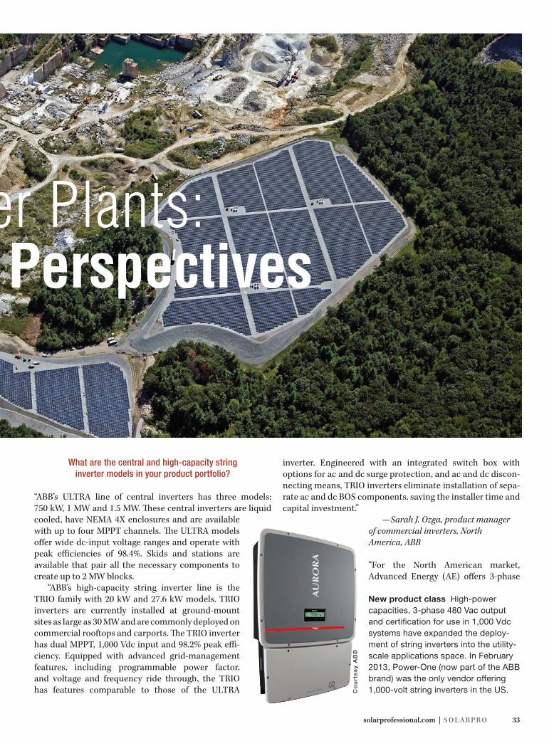
Centralized & Decentralized PV Power Plants:
As the capacity of utility-scale PV plants has increased in the US, so has the capacity of the centralized power-conditioning units used in these projects. Today, many plants utilize factory-integrated skids that combine inverters, medium-voltage transformers and switchgear into packages that range in capacity from 1 MW to 2.5 MW. These integrated systems offer project develop-ers many advantages, including optimized component com-patibility, as well as reduced installation time and expense. While the size and sophistication of centralized solutions continues to grow, an increasingly com-pelling trend is occurring in what are best described as small utility-scale systems (<50 MW) that challenges the centralized “bigger is better” power conditioning system approach.
In the last two years, the industry has seen the develop-ment and introduction of a new class of high-capacity string inverters that are well suited for both commercial and indus-trial use and increasingly are showing up in utility-scale power plants. Many of these units are rated for 1,000 Vdc and allow string lengths (and corresponding material and installa-tion cost reductions) matching those of designs using central inverters. In addition, most of these string inverter models offer native 3-phase 480 Vac output that is well suited for inte-gration with the medium-voltage transmission systems used in utility-scale PV power plants.
To get a well-rounded perspective on the project vari-ables and deliverables that drive the centralized or decen-tralized design decision and how installers are deploying large-scale string inverter systems in the field, I reached out to nine power-conditioning system manufacturers active in
the US market. Of these nine vendors, six manufacture or distribute both high-capacity string inverters and central inverters suitable for utility-scale projects. These compa-nies include ABB, AE Solar Energy, KACO new energy, SMA America, Solectria and Sungrow. The remaining three ven-dors—Chint Power Systems, Fronius and SolarEdge—offer string inverters but not large central inverters in the US.
As with many PV design decisions, an individual project’s characteristics and site challenges, as well as the capabili-ties and limitations of the available equipment, ultimately drive a system’s general architecture and product specifica-tion. While both centralized and decentralized designs have bright futures in the North American market, contemporary string inverter–based power-conditioning solutions offer project developers an additional and potentially compelling option to consider.
solarprofessional.com | S O L A R PR O 33
Co
urt
es
y A
BB
What are the central and high-capacity string inverter models in your product portfolio?
“ABB’s ULTRA line of central inverters has three models: 750 kW, 1 MW and 1.5 MW. These central inverters are liquid cooled, have NEMA 4X enclosures and are available with up to four MPPT channels. The ULTRA models offer wide dc-input voltage ranges and operate with peak efficiencies of 98.4%. Skids and stations are available that pair all the necessary components to create up to 2 MW blocks.
“ABB’s high-capacity string inverter line is the TRIO family with 20 kW and 27.6 kW models. TRIO inverters are currently installed at ground-mount sites as large as 30 MW and are commonly deployed on commercial rooftops and carports. The TRIO inverter has dual MPPT, 1,000 Vdc input and 98.2% peak effi-ciency. Equipped with advanced grid-management features, including programmable power factor, and voltage and frequency ride through, the TRIO has features comparable to those of the ULTRA
inverter. Engineered with an integrated switch box with options for ac and dc surge protection, and ac and dc discon-necting means, TRIO inverters eliminate installation of sepa-rate ac and dc BOS components, saving the installer time and capital investment.”
—Sarah J. Ozga, product manager of commercial inverters, North America, ABB
“For the North American market, Advanced Energy (AE) offers 3-phase
Vendor Perspectives
Centralized & Decentralized PV Power Plants:
New product class High-power capacities, 3-phase 480 Vac output and certification for use in 1,000 Vdc systems have expanded the deploy-ment of string inverters into the utility-scale applications space. In February 2013, Power-One (now part of the ABB brand) was the only vendor offering 1,000-volt string inverters in the US.

34 S O L A R PR O | March/April 2015
string inverters ranging from 12 kWac to 23 kWac, as well as central inverters up to 1 MWac per single inverter. In late 2015, AE will complement the portfolio with a higher-capacity string inverter targeting the large commercial and utility-scale segment, based on the topology of the 40/46 kWac inverter already available in the International Electrotechnical Com-mission (IEC) markets. All products are suitable for and proven in utility-scale applications and are aimed to achieve lowest cost of energy throughout the project life cycle.”
—Verena Sheldon, senior manager of field applications, AE Solar Energy
“Chint Power Systems (CPS) is currently shipping four 3-phase string inverter models. The 14 kW and 20 kW units are for 600 Vdc applications, and the 23 kW and 28 kW models are designed for 1,000 Vdc systems. While we do have large multi-MW installations with our 600 Vdc line, the majority of large-scale systems are designed with the 1,000 Vdc product line. The 23 kW and 28 kW inverters are dual MPPT, with best-in-class efficiency at 98% CEC, and ship with a standard inte-grated wiring box that is also separable. They offer integrated AFCI functionality and high-power output at 480 Vac. Users can install the inverters in vertical or horizontal (15°) orienta-tions. The entire product line ships standard with advanced utility-interactive control features including remote power-factor control, reset and dynamic ramp-rate control.”
—Sukriti Jain, applications engineer, Chint Power Systems, North America
“Fronius now offers the Fronius Symo line of string invert-ers designed for commercial and utility 3-phase systems. The Symo portfolio comprises nine lightweight, transformerless 1,000 Vdc inverters with dual MPPTs. Symo 240/208 Vac and 480 Vac models are available from 10 kW to 24 kW.”
—Moe Mahone, key account manager of commercial sales, US, Fronius
“KACO new energy’s central inverter family includes the XP500U-TL, XP550U-TL, blueplanet 750 TL3, blueplanet 875 TL3 and blueplanet 1000 TL3. All models have a large range of reactive power support (0.2 lead/lag) and full apparent power (kVA) at 50°C, and are compatible with most global grid codes for utility interaction. Distributed 3-phase string inverter models include blueplanet 32.0, 40.0 and 50.0 TL3, and Powador 60.0 and 72.0 TL3. The blueplanet inverters are listed to UL 1741 standards. The Powador models are CE certified for international use. All string inverter models have a large range of reactive power support (0.6 lead/lag) and full apparent power (kVA) at 50°C or higher, and are compatible with most global grid codes for utility interaction.”
—Bill Reaugh, senior director of product management, KACO new energy
“SMA’s utility-scale product portfolio includes string and central inverters for systems 2 MW or greater and intercon-necting at medium voltage. SMA’s string inverter solution for projects of this size—where array-mounted dc combiners are not required, since the inverter itself takes their place—is the Sunny Tripower. The Tripower series allows for a decentral-ized design for utility-scale plants and includes 3-phase 480 Vac, 4-wire models from 12 kW to 24 kW with built-in AFCI, dc step-up and dual MPPT inputs for maximum string flexibility. The 60 kW MLX 60 string inverter completes the product family.
“For central inverters, SMA offers 19 Sunny Central mod-els ranging from 500 kW to 2,500 kW. For a complete system solution, the Compact Medium Voltage Power Platform and Utility Power System solutions package central inverters, medium-voltage transformers and all related BOS equip-ment as a complete assembly built in a controlled envi-ronment. SMA’s central inverter portfolio gives designers opportunities for 600 Vdc, 1,000 Vdc and 1,500 Vdc systems; a variety of MPPT and operating ranges; multiple inputs and fuse sizes; proven grid support C O N T I N U E D O N PA G E 3 6
Uti l i ty-Scale PV PlantsC
ou
rte
sy
SM
A A
me
ric
a
The power of choice Six of the vendors surveyed for this article offer broad ranges of power-conditioning equipment, including both central and string inverters. For example, SMA’s product portfolio includes the 2 MW Sunny Central 2000-US and the 24 kW Sunny Tripower. Both are suitable for systems that connect at medium voltage.

The best solar tracking system under the sun.Il miglior sistema di inseguimento solare sotto il sole.El mejor sistema de seguimiento solar bajo el sol.Le meilleur système de poursuite solaire sous le soleil.太陽の下で最高の太陽追尾システム。
[email protected] 1.855.TRACKPV arraytechinc.com
Great engineering is a universal language.With installations in nearly 20 countries around the globe, Array’s tracking and racking systems’ reliability, flexibility
and durability mean success in any language. The simple design, ability to utilize uneven terrain and ease of
installation have been proven in this planet’s extremes—from the sub-zero arctic to the scorching deserts to
sweltering tropical humidity. Supporting over two gigawatts of solar generation and with more than two decades
of experience, working with Array Technologies puts some of the most experienced ground mount system
engineers on the planet behind you and your project. Choose the best. Choose the DuraTrack HZ and have a
world of difference delivered to your job site. Anywhere!

36 S O L A R PR O | March/April 2015
Co
urt
es
y C
hin
t P
ow
er
Sy
ste
ms
functionality; reactive power capabilities; class-leading efficiencies; and the highest power densities available.”
—Ryan LeBlanc, senior application engineer, SMA America
“SolarEdge’s SE20k model is a 20 kWac inverter that provides a distributed gen-eration solution for today’s utility PV plants. Combined with our P700 2-to-1 power optimizers that allow connection of two 72-cell modules in series, the SE20k offers high-energy yield, increased design flexibility, module-level monitoring and SafeDC architecture.”
—Dru Sutton, technical marketing man-ager, SolarEdge
“Solectria offers three 1,000 Vdc, 3-phase 480 Vac trans-formerless string inverters with capacities of 23 kWac, 28 kWac and 36 kWac. The inverters feature dual MPPT with four fused inputs per tracker. Solectria’s 1,000 Vdc, 3-phase 380 Vac central inverter models include the 500 kW SGI 500XTM and the 750 kW SGI 750XTM. Both models are designed for direct connection to an external transformer and can be configured as 1 MW or 1.5 MW Solar Stations. Available utility-scale options include a plant master con-troller and advanced grid-management features such as voltage and frequency ride through, reactive power control, real power curtailment and power factor control.”
—Eric Every, senior applications engineer, Solectria— A Yaskawa Company
“Sungrow central units include the 600 Vdc SG500LV and three 1,000 Vdc models, the SG750MX, SG800MX and SG1000MX. We offer three high-capacity string inverters, including the 480 Vac SG30KU and SG36KU, and the 380/400 Vac SG60KU. All inverters feature 10% overload capability at a 0.9 power factor up to 50˚C ambient. The central invert-ers have customizable dc input options, including fuses or a direct busbar connection, and an optional dc breaker cabi-net. The 30 kW and 36 kW string inverters feature 10 moni-tored dc inputs. The 60 kW unit has eight MC4 inputs. The use of Branch ‘Y’ MC4 connectors in the PV array allows for cable savings by requiring only one homerun to the SG60KU per two strings. The SG60KU is one of the first units to use silicon carbide power components, allowing us to nearly double the power density. This, combined with advanced cooling techniques, allows for a lower cost per watt, as well as lower labor and BOS costs.”
—Paul Mync, technical sales manager, Sungrow USA
How has the introduction of high-power 1,000 vdc, 3-phase 480 vac string inverters impacted the design choices
available for utility-scale PV plants?
“1,000 Vdc string inverters open up potential sites for utility-scale plants that central inverters previously could not serve due to shading, noncontiguous land segments or uneven land requiring arrays of different tilts or azimuths. The decentral-ized architecture of string-inverter systems also distributes the weight load, allowing installations on landfill sites with weight restrictions. The 3-phase string inverters allow more flexibility in the PV plant size, so you can size plants in incre-ments of 20 kW and not in 100 kW blocks. Additionally, ABB 3-phase string inverters have a 10-year warranty in contrast to the standard 5-year warranty for central inverters.”
—Sarah J. Ozga, ABB
“The availability of high-efficiency transformerless 3-phase string inverters and code changes that facilitate 1,000 Vdc systems make string inverters a competitive option for utility-scale applications. Giving system designers and integrators the opportunity to choose from these different topologies increases design flexibility. The specific system details, financial met-rics or site-specific design challenges or limitations drive the decision. With string inverters becoming a viable option for utility-scale applications, system designers and installers can transition more easily from commercial applications to utility scale, since they would be using the same equipment.”
—Verena Sheldon, AE Solar Energy
“The impact is positive. We see an increasing number of devel-opers evaluating 3-phase string inverters for utility-scale power plant applications. The adoption of a decentralized approach for projects ranging from 2 MW to 5 MW began in 2013, and we see this trend continuing into the future. CPS is releasing a
High-voltage in and out String inverters with 1,000 Vdc input and 3-phase 480 Vac output are well suited for some utility-scale applications. Chint Power Systems offers 23 kWac and 28 kWac 1,000 Vdc models with dual MPPT inputs for commercial, industrial and utility projects.
Uti l i ty-Scale PV Plants

solarprofessional.com | S O L A R PR O 37
36 kW string inverter this year and will follow with higher-power units designed specifically for utility-scale applications.”
—Sukriti Jain, Chint Power Systems, North America
“Fronius has been a front-runner in the US solar industry’s shift of consciousness toward a distributed inverter topology. The European market frequently leads design trends, such as allow-ing 1,000 Vdc residential and commercial systems. The flexibil-ity that string inverters provide makes them an ideal choice for both simple and complex designs.”
—Moe Mahone, Fronius
“The introduction of 1,000-volt high-power (30 kWac–60 kWac) string inverters provides more design choices to developers and system integrators. The major benefits of string inverters include improvements in energy harvest due to a larger number of MPPTs, an increase in availability and a reduction in down-time when issues occur. However, the increase in the number of inverters can make interconnection design more complex. The communications and control infrastructure can also be more complicated due to the larger number of devices.”
—Bill Reaugh, KACO new energy
“With the introduction of 1,000 Vdc 3-phase string inverters, utility-scale projects now have a distinct new option available. Companies can deliver, install and maintain string inverters differently from how they manage larger central units, with comparable capital expenditure (CAPEX) costs. For projects in difficult terrain, such as brownfields and landfills, and complex rooftops, the ability to distribute inverters through-out the array, and in many cases take advantage of the same mounting equipment the PV is already using, can make some projects possible that otherwise would not be due to acces-sibility or other site-specific restrictions.
“Utilizing string inverters in large-scale plants has had a game-changing effect on transportation logistics, installation practices and, perhaps most notably, on long-term O&M. One or two people can replace string inverters, and companies can keep spare units on-site. This reduces or eliminates altogether the need for coordinating specialized service personnel or lift-ing equipment. String inverters also distribute independent MPPT inputs throughout a site, which can lead to improved energy production, and by their nature these units provide exceedingly granular operating data, often down to just a few strings, all at no additional cost. The decentralized architec-ture can help stakeholders install more easily, identify prob-lems faster and produce more power over the life of the plant.”
—Ryan LeBlanc, SMA America
“SolarEdge’s 1,000 Vdc inverters operate at a fixed voltage of 850 Vdc, providing an optimum conversion point from dc to 480 Vac without added buck or boost steps. Our module-level
w w w. h e y c o . c o m
“Stay Connected with Heyco” Power ComponentsBox 517 • Toms River, NJ 08754 • P: 732-286-4336 • F: 732-244-8843
For FREE samples or product literature,call toll free 1-800-526-4182, or visit heyco.com
HEYClip™ SunRunner® 2,2-R, and 2-U Cable ClipsTo hold Micro-Inverter Cables .413˝ (10,5 mm) to .472˝(12,0 mm) dia. on mounting frames and racking systems.
HEYClip™ SunRunner® Cable ClipsDouble-Compression Design for (1) 12 gaugeUSE-2 to (2) 10 gauge PV-1000V wires. Cables from .20˝ (5,1 mm) to .30˝ (7,6 mm) dia., and frames up to .125˝ (3,2 mm) thick.Now available in 316 Stainless Steel.
HEYClip™ SunRunner® 90°Cable ClipsMounts at 90° angle to the originalSunRunner, holds a single cable from.20˝ (5,1 mm) to .30˝ (7,6 mm). For use withPV modules mounted in “Landscape” Mode.
Heyco®
Wire ManagementSolutions for Solar
Installers & Integrators
HEYClip™ SunRunner 4™
Cable ClipDouble-Compression Design for up to (4) 12 gauge USE-2 or (4) 10 gauge PV-1000V wires,and racking systems up to .250” (6,4 mm) thick.
HEYClip™ Nylon UVX* SunRunner® 2Series Cable ClipsTo hold Micro-Inverter Cables .413˝ (10,5 mm) to ,472˝ (12,0 mm) dia. onmounting frames and racking systems.*Extended UV Protection
HEYClip™ SunRunner® EZ™
Cable ClipDouble-Compression Design for up totwo (2) wires .20˝ (5,1 mm) to .30˝ (7,6 mm),and panels up to .250” (6,4 mm) thick.
NEW
3365 Heyco 3.4x9.6_Layout 1 2/3/15 3:29 PM Page 1

38 S O L A R PR O | March/April 2015
optimization system allows integrators to size lon-ger strings, about 2.3 times longer than with tra-ditional 1,000 Vdc systems and more than 4 times longer than with traditional 600 Vdc systems.”
—Dru Sutton, SolarEdge
“There is a perception in the industry that string inverters allow the designer to minimize land preparation because the granularity allows for greater tolerance in site topology. For utility-scale projects 5 MW and larger, these benefits are marginal. Customers are achieving impressive energy yields using central inverters on land with widely varying topology. Our customers continue to evaluate appropriate solutions on a case-by-case basis.”
—Eric Every, Solectria
“Metaphorical stars have aligned with the intro-duction of high-powered 3-phase string inverters, 1,000 Vdc systems and declining string inverter prices. Historically, the high cost per watt of string inverters limited their use in utility-scale projects. Substantial price drops in 3-phase string inverters have closed the gap. From a system perspective, deploying multiple string inverters in a utility-scale system is akin to the rapid growth in market share of microinverters in the residential segment. Modularity, granularity and redun-dancy all have played a role in the adoption of 3-phase string inverters on larger systems. With string inverters, you have more MPPTs, less downtime and greater energy harvest, all leading to a change in the design of utility-scale systems.”
—Paul Mync, Sungrow USA
What attributes of decentralized utility-scale string inverter systems make them a compelling
value proposition for some projects? What are the limitations when compared to
centralized systems?
“In terms of ABB products, 3-phase string inverters offer MPP optimization at a finer granularity, with one channel of the TRIO inverter optimizing the MPPT for each 8 kW–16 kW of the system. In contrast, the ULTRA inverter optimizes the MPPT for 390 kW of the system. The TRIO’s more- granular MPPT optimization supports installations with shading, noncontiguous land segments and uneven ter-rain. Additionally, TRIO string inverters, which weigh less than 170 pounds, obviate the costs for cranes or forklifts. For utility-scale sites, the 480 Vac output voltage requires a step-up transformer for the utility medium-voltage transmission connection at 2.3 kV–25 kV. String inverter outputs combine
at ac panels before connecting to the transformer. When using a central inverter, you do not need to combine the ac. One clear limitation for string inverters is the current trend of utility-scale projects designed at 1,500 Vdc, a system voltage that string inverters do not yet address.”
—Sarah J. Ozga, ABB
“The decentralized approach offers greater design flexibil-ity and can solve a number of challenges that can be harder, or in some cases impossible, to overcome with a central-ized approach—space constraints or weight limitations, for example. Because string inverters are light and have small footprints, installers can mount them directly at the back of the array. With this placement option, shading and required row space are far less significant issues than they would be with a central inverter. Weight per unit can become a decision criterion on sites with unstable ground, such as landfills. The main challenge in utility-scale string inverter systems is the increased complexity of the monitoring and control system, which the use of equipment suitable for the specific applica-tion can easily overcome.”
—Verena Sheldon, AE Solar Energy
“The primary benefit of a decentralized approach is to increase system uptime and performance. If an inverter fail-ure occurs with a central inverter, a large loss of production occurs. A smaller inverter building block
Co
urt
es
y A
E S
ola
r E
ne
rgy
an
d g
roS
ola
r
Heavy lifting Central inverters and integrated power-conditioning skids or enclosures require heavy equipment for transport and place-ment. Weight-constrained sites, such as landfills, and sites with poor access may benefit from decentralized designs.
C O N T I N U E D O N PA G E 4 0
Uti l i ty-Scale PV Plants
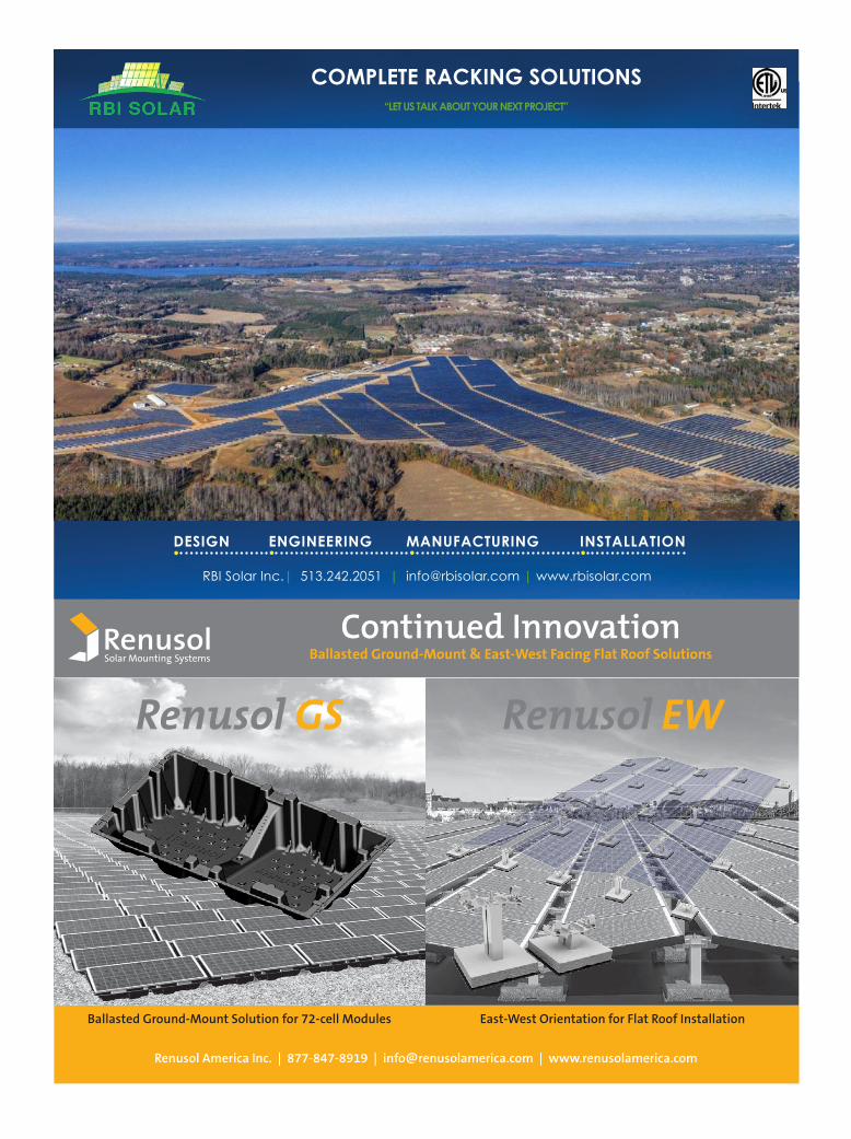
RBI Solar Inc.| 513.242.2051 | [email protected] | www.rbisolar.com
COMPLETE RACKING SOLUTIONS“LET US TALK ABOUT YOUR NEXT PROJECT”
DESIGN ENGINEERING MANUFACTURING INSTALLATION. . . .
Renusol America Inc. | 877-847-8919 | [email protected] | www.renusolamerica.com
Renusol GS Renusol EW
Ballasted Ground-Mount Solution for 72-cell Modules
Continued InnovationBallasted Ground-Mount & East-West Facing Flat Roof Solutions
East-West Orientation for Flat Roof Installation
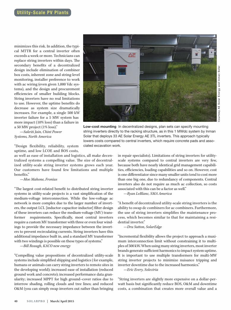
40 S O L A R PR O | March/April 2015
minimizes this risk. In addition, the typi-cal MTTR for a central inverter often exceeds a week or more. Technicians can replace string inverters within days. The secondary benefits of a decentralized design include elimination of combiner box costs, inherent zone and string-level monitoring, installer preference to work with ac wiring (even given 1,000 Vdc sys-tems), and the design and procurement efficiencies of smaller building blocks. String inverters have no real limitations to use. However, the uptime benefits do decrease as system size dramatically increases. For example, a single 500 kW inverter failure for a 5 MW system has more impact (10% loss) than a failure in a 50 MW project (1% loss).”
—Sukriti Jain, Chint Power Systems, North America
“Design flexibility, reliability, system uptime, and low LCOE and BOS costs, as well as ease of installation and logistics, all make decen-tralized systems a compelling value. The size of decentral-ized utility-scale string inverter systems grows each year. Our customers have found few limitations and multiple benefits.”
—Moe Mahone, Fronius
“The largest cost-related benefit to distributed string inverter systems in utility-scale projects is a vast simplification of the medium-voltage interconnection. While the low-voltage ac network is more complex due to the larger number of invert-ers, the output LCL [inductor-capacitor-inductor] filter design of these inverters can reduce the medium-voltage (MV) trans-former requirements. Specifically, most central inverters require a custom MV transformer with three or even four wind-ings to provide the necessary impedance between the invert-ers to prevent recirculating currents. String inverters have this additional impedance built in, and a standard MV transformer with two windings is possible on these types of systems.”
—Bill Reaugh, KACO new energy
“Compelling value propositions of decentralized utility-scale systems include simplified shipping and logistics ( for example, humans or animals can carry string inverters to remote sites in the developing world); increased ease of installation (reduced ground work and concrete); increased performance data gran-ularity; increased MPPT for high ground–cover ratios due to interrow shading, rolling clouds and tree lines; and reduced O&M (you can simply swap inverters out rather than bringing
in repair specialists). Limitations of string inverters for utility- scale systems compared to central inverters are very few, because both have nearly identical grid management capabili-ties, efficiencies, loading capabilities and so on. However, cost is one differentiator since many smaller units tend to cost more than one big one, due to redundancy of components. Central inverters also do not require as much ac collection, so costs associated with this can be a factor as well.”
—Ryan LeBlanc, SMA America
“A benefit of decentralized utility-scale string inverters is the ability to swap dc combiners for ac combiners. Furthermore, the use of string inverters simplifies the maintenance pro-cess, which becomes similar to that for maintaining a resi-dential inverter.”
—Dru Sutton, SolarEdge
“Incremental flexibility allows the project to approach a maxi-mum interconnection limit without constraining it to multi-ples of 500 kW. When using many string inverters, most inverter brands generate sufficient harmonics to impact system uptime. It is important to use multiple transformers for multi-MW string inverter projects to minimize nuisance tripping and inverter downtime due to the increased harmonics.”
—Eric Every, Solectria
“String inverters are slightly more expensive on a dollar-per-watt basis but significantly reduce BOS, O&M and downtime costs, a combination that creates more overall value and a
Co
urt
es
y A
E S
ola
r E
ne
rgy
an
d I
nm
an
So
lar
Low-cost mounting In decentralized designs, plan sets can specify mounting string inverters directly to the racking structure, as in this 1 MWdc system by Inman Solar that deploys 33 AE Solar Energy AE 3TL inverters. This approach typically lowers costs compared to central inverters, which require concrete pads and asso-ciated excavation work.
Uti l i ty-Scale PV Plants

solarprofessional.com | S O L A R PR O 41
lower LCOE compared to a centralized approach. Projects in remote locations can benefit from distributed designs due to maintenance concerns and a lack of on-site techni-cal resources. System downtime and O&M take on a different perspective when coupled with decentralized string inverters. A failed inverter does not necessarily mean a developer has to roll a truck immediately. A previously scheduled routine pre-ventative maintenance visit could include the service call. You have lower operational costs since you do not need to dispatch a high-level inverter technician to troubleshoot and replace a string inverter. Of course, there are limitations. For large proj-ects, the sheer number of 3-phase string inverters required is often enough to make a developer nervous. While it may not be an accurate viewpoint, the concept of having more points of failure can deter developers. Also, central invert-ers are slightly less expensive than string inverters. Because larger projects operate on slim margins, the increased cost of 3-phase string inverters could be just enough to keep a project from penciling out.”
—Paul Mync, Sungrow USA
Considering financial metrics such as LCOE, how has the financial comparison between
centralized and decentralized systems changed in recent years?
“Due to the higher cost per watt of string inverters and the added cost for ac combining panels and lower capacity power transformers, the LCOE for central inverters is advantageous for systems over approximately 2 MW.”
—Sarah J. Ozga, ABB
“When comparing centralized and decentralized systems based on financial metrics, the advantages and cost savings of the decentralized approach are most obvious for smaller sys-tems. With increasing system size, the delta becomes smaller and eventually reaches an inflection point at which the lines cross and the centralized approach becomes more competi-tive. While the general shape of the curve has remained very similar over the years, the inflection point has moved to much larger system sizes. Changes in equipment cost, as well as the acceptance and availability of 1,000 Vdc–rated products, are factors in this development. The availability of higher- capacity string inverters will shift that crossover point to even larger system sizes.”
—Verena Sheldon, AE Solar Energy
“In addition to providing the benefits described earlier, 3-phase string inverters have dropped significantly in cost over the last two years as volumes have increased, with 3-phase string prices approaching central inverter pricing.”
—Sukriti Jain, Chint Power Systems, North America
“As always, the goal of any system designer, operator or owner is to maximize energy production. Decentralized systems have benefited from the price drop in string inverters, but the change to 1,000 V systems allowing for longer dc strings and lower BOS costs has probably had a larger impact.”
—Moe Mahone, Fronius
“The LCOE comparisons have narrowed considerably when you factor in O&M costs associated with central inverters. In most cases, ongoing O&M and warranty service costs, partic-ularly on smaller (<20 MW) projects, have more than offset the reduced first cost of central inverter systems. For the small-est (<5 MW) projects, the LCOE for a distributed architecture is actually better than for central inverter designs. Of course, you need to consider the cost of labor. As overall system costs have decreased, the labor component has become an increas-ingly large portion of the first system cost. In states with high labor costs, this alone can be the deciding factor between cen-tral (skid-integrated) and distributed designs.”
—Bill Reaugh, KACO new energy
“The cost of string inverters in recent years has declined sig-nificantly—more rapidly than that of central inverters—due to increased power classes and improved production meth-ods. Therefore, LCOE has seen a convergence in recent years to a point where distinguishing factors are project specific, with the costs of decentralized systems equaling—and then perhaps improving upon—centralized system costs. Some sites favor one approach, while other sites are more favorable to the other. What the solar industry is experiencing today is almost a push at the CAPEX level, but modestly improved
Co
urt
es
y S
un
gro
w
Centralized design Developed by Canadian Solar and White Construction, the 28.4 MWdc TA Acacia PV plant in Lancaster, CA, features a centralized system architec-ture. Twenty-five Sungrow SG800MX central inverters pro-vide power conditioning for the project’s 94,340 Canadian Solar modules.
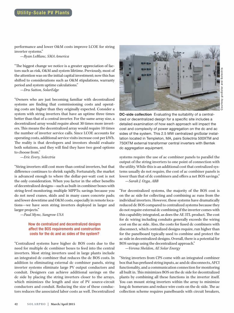
42 S O L A R PR O | March/April 2015
Co
urt
es
y g
roS
ola
r a
nd
So
lec
tria
performance and lower O&M costs improve LCOE for string inverter systems.”
—Ryan LeBlanc, SMA America
“The biggest change we notice is a greater appreciation of fac-tors such as risk, O&M and system lifetime. Previously, most of the attention was on the initial capital investment; now this has shifted to considerations such as O&M stipulations, warranty period and system uptime calculations.”
—Dru Sutton, SolarEdge
“Owners who are just becoming familiar with decentralized systems are finding that commissioning costs and operat-ing costs are higher than they originally expected. Consider a system with string inverters that have an uptime three times better than that of a central inverter. For the same array size, a decentralized array would require about 30 times more invert-ers. This means the decentralized array would require 10 times the number of inverter service calls. Since LCOE accounts for operating costs, additional service visits increase cost per kWh. The reality is that developers and investors should evaluate both solutions, and they will find they have two good options to choose from.”
—Eric Every, Solectria
“String inverters still cost more than central inverters, but that difference continues to shrink rapidly. Fortunately, the market is advanced enough to where the dollar-per-watt cost is not the only consideration. When you factor in the other benefits of decentralized designs—such as built-in combiner boxes with string-level monitoring; multiple MPPTs; savings because you do not need cranes, skids and in many cases concrete pads; and lower downtime and O&M costs, especially in remote loca-tions—we have seen string inverters deployed in larger and larger projects.”
—Paul Mync, Sungrow USA
How do centralized and decentralized designs affect the BOS requirements and construction costs for the dc and ac sides of the system?
“Centralized systems have higher dc BOS costs due to the need for multiple dc combiner boxes to feed into the central inverters. Most string inverters used in large plants include an integrated dc combiner that reduces the dc BOS costs. In addition to eliminating external dc combiner panels, string inverter systems eliminate large PV output conductors and conduit. Designers can achieve additional savings on the dc side by placing the string inverters closer to the arrays, which minimizes the length and size of PV source-circuit conductors and conduit. Reducing the size of these conduc-tors reduces the associated labor costs as well. Decentralized
systems require the use of ac combiner panels to parallel the output of the string inverters to one point of connection with the utility. While this is an additional cost that centralized sys-tems usually do not require, the cost of ac combiner panels is lower than that of dc combiners and offers a net BOS savings.”
—Sarah J. Ozga, ABB
“For decentralized systems, the majority of the BOS cost is on the ac side for collecting and combining ac runs from the individual inverters. However, these systems have dramatically reduced dc BOS compared to centralized systems because they do not require external dc combining if the inverter comes with this capability integrated, as does the AE 3TL product. The cost for dc wiring including conduits generally exceeds the wiring cost on the ac side. Also, the costs for fused dc combiners with disconnect, which centralized designs require, run higher than for the panelboard typically used to combine and protect the ac side in decentralized designs. Overall, there is a potential for BOS savings using the decentralized approach.”
—Verena Sheldon, AE Solar Energy
“String inverters from CPS come with an integrated combiner box that has prefused string inputs, ac and dc disconnects, AFCI functionality, and a communication connection for monitoring all built in. This minimizes BOS on the dc side for decentralized plants by combining all these functions in the inverter itself. You can mount string inverters within the array to minimize long dc homeruns and reduce wire costs on the dc side. The ac collection scheme requires panelboards with circuit breakers,
DC-side collection Evaluating the suitability of a central-ized or decentralized design for a specific site includes a detailed examination of how each approach will impact the cost and complexity of power aggregation on the dc and ac sides of the system. This 2.5 MW centralized groSolar instal-lation located in Templeton, MA, pairs Solectria 500XTM and 750XTM external transformer central inverters with Bentek dc aggregation equipment.
Uti l i ty-Scale PV Plants

solarprofessional.com | S O L A R PR O 43
which you can also mount either within the array or next to the transformers, depending on the project layout.”
—Sukriti Jain, Chint Power Systems, North America
“With the availability of dual MPPT 1,000 V string inverters, dc strings can now be much longer and more efficient, and require less, if any, string fusing before the inverter. Due to the mass production of standard ac components, the cost is typically much lower than for specially produced dc compo-nents. Mounting inverters at the array alleviates the need for the costly engineering, parts and labor involved in building a concrete pad or the crane lifting sometimes needed for mount-ing a central inverter.”
—Moe Mahone, Fronius
“With regard to distributed architectures, the smaller num-ber of conductors and the lower currents reduce the cost per combiner box for the dc collection; however, the potential for an increased quantity of combiner boxes may offset that advantage. On the ac side, we see a significant potential for cost savings. Manufacturers sell most central inverters to projects
in pairs integrated onto skids. To reduce inverter cost, most central inverters require the use of three- or four-winding MV transformers. These custom-designed transformers lead to higher first costs and higher maintenance costs down the road. With distributed inverters, the additional impedance required to prevent recirculating currents already exists, so you can use utility-standard two-winding MV transformers. This seem-ingly small change can significantly reduce up-front costs and ongoing maintenance costs.”
—Bill Reaugh, KACO new energy
“For short distances, it is generally more cost effective to route power through ac conductors as opposed to dc conductors. DC circuit ampacities have larger safety factors, and dc circuit con-ductors carry 73% more current than the 3-phase equivalent,
Explore opportunities in the renewable energy fi eld
2015 Featured CoursesPV Site Assessor Training | PV 201
PV Sales and Finance | PV 203
PV and Solar Thermal Structural Considerations | PV-ST 411
2014 National Electrical Code Update for PV | PV 614
Online Solar Training Courses Midwest Renewable Energy Association
Learn from an expert instructor at your own pace. The Midwest Renewable Energy Association (MREA) offers a diverse selection of online courses for every level.
Many courses fulfi ll professional credentialing and continuing education credits requirements.
To explore, learn more and register, visit us online atwww.midwestrenew.org/courses or call 715-592-6595.
Inverter 1
Utility
Inverter 2
Multi-winding transformer System design-ers often need to specify multi-winding transformers to connect central inverters in parallel on the same transformer, as shown here. However, they can use standard two-winding transformers when paralleling string inverters, which integrate and interconnect via an LCL output filter.
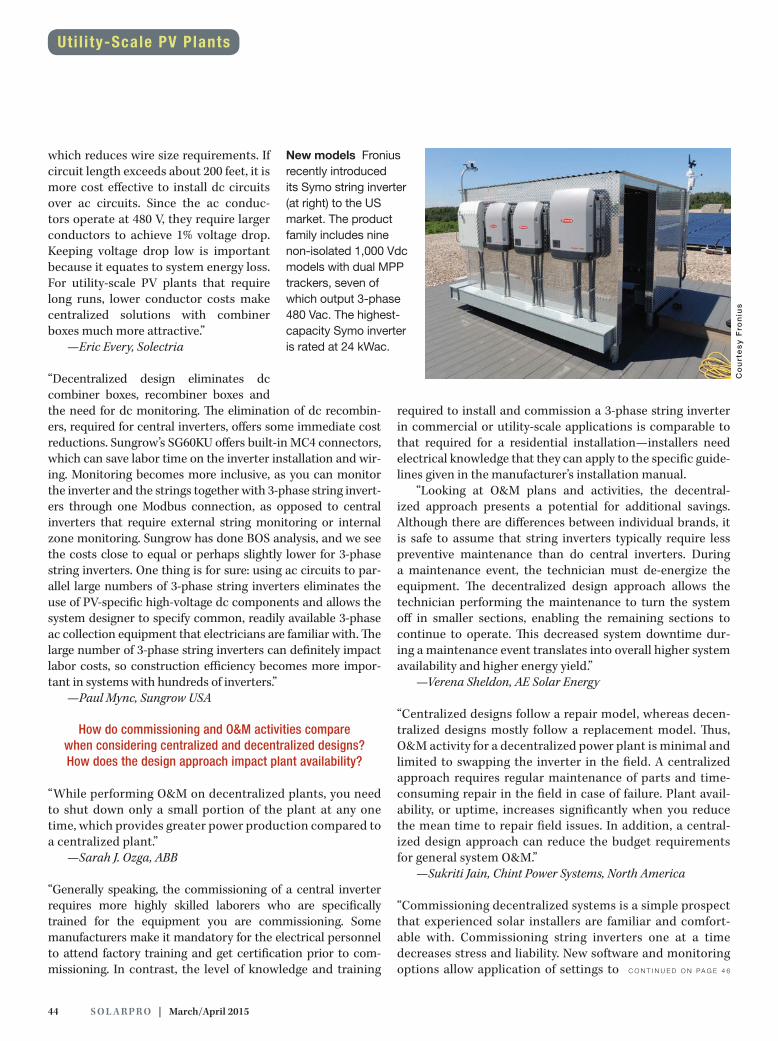
44 S O L A R PR O | March/April 2015
which reduces wire size requirements. If circuit length exceeds about 200 feet, it is more cost effective to install dc circuits over ac circuits. Since the ac conduc-tors operate at 480 V, they require larger conductors to achieve 1% voltage drop. Keeping voltage drop low is important because it equates to system energy loss. For utility-scale PV plants that require long runs, lower conductor costs make centralized solutions with combiner boxes much more attractive.”
—Eric Every, Solectria
“Decentralized design eliminates dc combiner boxes, recombiner boxes and the need for dc monitoring. The elimination of dc recombin-ers, required for central inverters, offers some immediate cost reductions. Sungrow’s SG60KU offers built-in MC4 connectors, which can save labor time on the inverter installation and wir-ing. Monitoring becomes more inclusive, as you can monitor the inverter and the strings together with 3-phase string invert-ers through one Modbus connection, as opposed to central inverters that require external string monitoring or internal zone monitoring. Sungrow has done BOS analysis, and we see the costs close to equal or perhaps slightly lower for 3-phase string inverters. One thing is for sure: using ac circuits to par-allel large numbers of 3-phase string inverters eliminates the use of PV-specific high-voltage dc components and allows the system designer to specify common, readily available 3-phase ac collection equipment that electricians are familiar with. The large number of 3-phase string inverters can definitely impact labor costs, so construction efficiency becomes more impor-tant in systems with hundreds of inverters.”
—Paul Mync, Sungrow USA
How do commissioning and O&M activities compare when considering centralized and decentralized designs? How does the design approach impact plant availability?
“While performing O&M on decentralized plants, you need to shut down only a small portion of the plant at any one time, which provides greater power production compared to a centralized plant.”
—Sarah J. Ozga, ABB
“Generally speaking, the commissioning of a central inverter requires more highly skilled laborers who are specifically trained for the equipment you are commissioning. Some manufacturers make it mandatory for the electrical personnel to attend factory training and get certification prior to com-missioning. In contrast, the level of knowledge and training
required to install and commission a 3-phase string inverter in commercial or utility-scale applications is comparable to that required for a residential installation—installers need electrical knowledge that they can apply to the specific guide-lines given in the manufacturer’s installation manual.
“Looking at O&M plans and activities, the decentral-ized approach presents a potential for additional savings. Although there are differences between individual brands, it is safe to assume that string inverters typically require less preventive maintenance than do central inverters. During a maintenance event, the technician must de-energize the equipment. The decentralized design approach allows the technician performing the maintenance to turn the system off in smaller sections, enabling the remaining sections to continue to operate. This decreased system downtime dur-ing a maintenance event translates into overall higher system availability and higher energy yield.”
—Verena Sheldon, AE Solar Energy
“Centralized designs follow a repair model, whereas decen-tralized designs mostly follow a replacement model. Thus, O&M activity for a decentralized power plant is minimal and limited to swapping the inverter in the field. A centralized approach requires regular maintenance of parts and time-consuming repair in the field in case of failure. Plant avail-ability, or uptime, increases significantly when you reduce the mean time to repair field issues. In addition, a central-ized design approach can reduce the budget requirements for general system O&M.”
—Sukriti Jain, Chint Power Systems, North America
“Commissioning decentralized systems is a simple prospect that experienced solar installers are familiar and comfort-able with. Commissioning string inverters one at a time decreases stress and liability. New software and monitoring options allow application of settings to
Co
urt
es
y F
ron
ius
New models Fronius recently introduced its Symo string inverter (at right) to the US market. The product family includes nine non-isolated 1,000 Vdc models with dual MPP trackers, seven of which output 3-phase 480 Vac. The highest-capacity Symo inverter is rated at 24 kWac.
C O N T I N U E D O N PA G E 4 6
Uti l i ty-Scale PV Plants

READY FOR YOUR CHALLENGES
The Best $/W Maximize your investmentAt Ingeteam we apply the concept of i+c to every project we undertake – innovation to find the best solution and commitment to provide the best service.
With a maximum efficiency level of up to 98.6%, Ingeteam’s PV inverters stand out for their $/W ratio, as they feature the best performance at the most competitive price. With 1GW annual production capacity in USA, Ingeteam’s commercial-scale (18kW-40kW) and utility-scale (375kVA-1,070kVA) UL compliant inverters, are available in Milwaukee, WI, where the company is headquartered. Thanks to its extensive O&M network, Ingeteam Inc is also able to provide the best service support to its customers.
Moreover, Ingeteam Inc has recently launched its new utility-scale battery inverters (375kVA-1,070kVA and UL compliant), aiming at storage systems that are coupled to PV plants.
The formula of the new energy
www.ingeteam.com
Visit us at:
MEE Middle East Electricity Dubai 2-4 March
ENR Lyon 4-6 March
Power & Electricity World South Africa 24-26 March
Solarex Istanbul 9-11 April
MIREC Mexico 19-20 May
Intersolar Munich 10-12 June
The Energy Fair Milwaukee 19-21 June
Intersolar Brazil Sao Paulo 1-3 September
CIREC Chile 8-10 September
SPI Anaheim 15-17 September
REI India 23-25 September
Green Expo Mexico 23-25 September
All Energy Australia 7-8 October
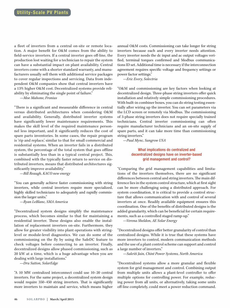
46 S O L A R PR O | March/April 2015
a fleet of inverters from a central on-site or remote loca-tion. A major benefit for O&M comes from the ability to field-service inverters. If a central inverter goes off-line, the production lost waiting for a technician to repair the system can have a substantial impact on plant availability. Central inverters come with a shorter standard warranty, and manu-facturers usually sell them with additional service packages to cover regular inspections and servicing. Data from inde-pendent O&M companies show that central inverters have a 13% higher O&M cost. Decentralized systems provide reli-ability by eliminating the single point of failure.”
—Moe Mahone, Fronius
“There is a significant and measurable difference in central versus distributed architectures when considering O&M and availability. Generally, distributed inverter systems have significantly lower maintenance requirements. This makes the skill level of the required maintenance person-nel less important, and it significantly reduces the cost of spare parts inventories. In some cases, the repair program is ‘rip and replace,’ similar to that for small commercial and residential systems. When an inverter fails in a distributed system, the percentage of the total system that goes offline is substantially less than in a typical central project. This, combined with the typically faster return to service on dis-tributed inverters, means that distributed architectures sig-nificantly improve availability.”
—Bill Reaugh, KACO new energy
“You can generally achieve faster commissioning with string inverters, while central inverters require more specialized, highly skilled technicians to adequately and rapidly commis-sion the larger units.”
—Ryan LeBlanc, SMA America
“Decentralized system designs simplify the maintenance process, which becomes similar to that for maintaining a residential inverter. These designs also enable the instal-lation of replacement inverters on-site. Furthermore, they allow for greater visibility into plant operations with string-level or module-level diagnostics. We can do some of the commissioning on the fly by using the SafeDC feature to check voltages before connecting to an inverter. Finally, decentralized designs allow phased commissioning, such as 20 kW at a time, which is a huge advantage when you are dealing with large installations.”
—Dru Sutton, SolarEdge
“A 10 MW centralized interconnect could use 10–20 central inverters. For the same project, a decentralized system design would require 350–450 string inverters. That is significantly more inverters to maintain and service, which means higher
annual O&M costs. Commissioning can take longer for string inverters because each and every inverter needs attention. Every inverter needs the dc input and ac output voltages veri-fied, terminal torques confirmed and Modbus communica-tions ID set. Additional time is necessary if the interconnection agreement requires specific voltage and frequency settings or power factor settings.”
—Eric Every, Solectria
“O&M and commissioning are key factors when looking at decentralized design. Three-phase string inverters offer quick installation and relatively simple commissioning procedures. With built-in combiner boxes, you can do string testing essen-tially after wiring up the inverter. You can set parameters via the LCD screen or remotely via Modbus. The commissioning of 3-phase string inverters does not require specially trained technicians. Central inverter commissioning can often require manufacturer technicians and an on-site supply of spare parts, and it can take more time than commissioning string inverters.”
—Paul Mync, Sungrow USA
What implications do centralized and decentralized designs have on inverter-based
grid management and control?
“Comparing the grid management capabilities and limita-tions of the inverters themselves, there are no significant differences between central and string inverters. The main dif-ference lies in the system control structure, which at first sight can be more challenging using a distributed approach. For system coordination, it is critical to provide a control struc-ture that allows communication with and control of several inverters at once. Readily available equipment ensures this coordination. One of the benefits of distributed designs is the added granularity, which can be beneficial for certain require-ments, such as a controlled staged ramp-up.”
—Verena Sheldon, AE Solar Energy
“Decentralized designs offer better granularity of control than centralized designs. While it is true that these systems have more inverters to control, modern communication methods and the use of a plant control scheme can support and control a large number of inverters.”
—Sukriti Jain, Chint Power Systems, North America
“Decentralized systems allow a more granular and flexible system for grid management and control. Combining output from multiple units allows a plant-level controller to offer multiple options for controlling power. For example, reduc-ing power from all units, or alternatively, taking some units off-line completely, could meet a power reduction command.
Uti l i ty-Scale PV Plants
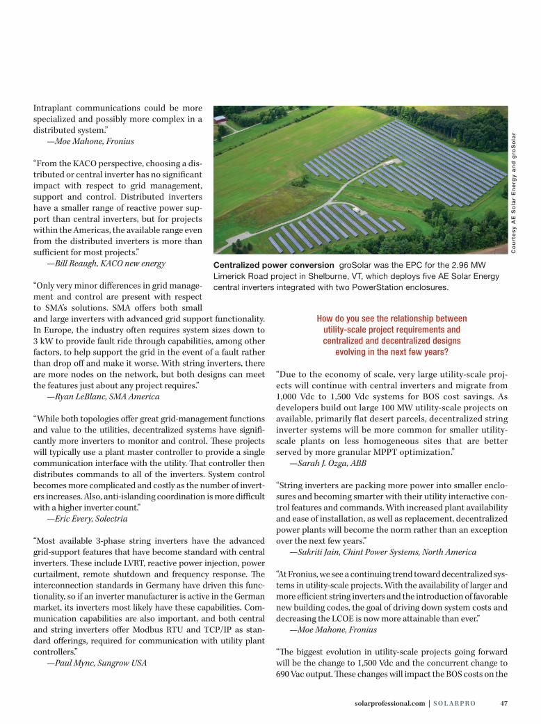
solarprofessional.com | S O L A R PR O 47
Intraplant communications could be more specialized and possibly more complex in a distributed system.”
—Moe Mahone, Fronius
“From the KACO perspective, choosing a dis-tributed or central inverter has no significant impact with respect to grid management, support and control. Distributed inverters have a smaller range of reactive power sup-port than central inverters, but for projects within the Americas, the available range even from the distributed inverters is more than sufficient for most projects.”
—Bill Reaugh, KACO new energy
“Only very minor differences in grid manage-ment and control are present with respect to SMA’s solutions. SMA offers both small and large inverters with advanced grid support functionality. In Europe, the industry often requires system sizes down to 3 kW to provide fault ride through capabilities, among other factors, to help support the grid in the event of a fault rather than drop off and make it worse. With string inverters, there are more nodes on the network, but both designs can meet the features just about any project requires.”
—Ryan LeBlanc, SMA America
“While both topologies offer great grid-management functions and value to the utilities, decentralized systems have signifi-cantly more inverters to monitor and control. These projects will typically use a plant master controller to provide a single communication interface with the utility. That controller then distributes commands to all of the inverters. System control becomes more complicated and costly as the number of invert-ers increases. Also, anti-islanding coordination is more difficult with a higher inverter count.”
—Eric Every, Solectria
“Most available 3-phase string inverters have the advanced grid-support features that have become standard with central inverters. These include LVRT, reactive power injection, power curtailment, remote shutdown and frequency response. The interconnection standards in Germany have driven this func-tionality, so if an inverter manufacturer is active in the German market, its inverters most likely have these capabilities. Com-munication capabilities are also important, and both central and string inverters offer Modbus RTU and TCP/IP as stan-dard offerings, required for communication with utility plant controllers.”
—Paul Mync, Sungrow USA
How do you see the relationship between utility-scale project requirements and centralized and decentralized designs
evolving in the next few years?
“Due to the economy of scale, very large utility-scale proj-ects will continue with central inverters and migrate from 1,000 Vdc to 1,500 Vdc systems for BOS cost savings. As developers build out large 100 MW utility-scale projects on available, primarily flat desert parcels, decentralized string inverter systems will be more common for smaller utility-scale plants on less homogeneous sites that are better served by more granular MPPT optimization.”
—Sarah J. Ozga, ABB
“String inverters are packing more power into smaller enclo-sures and becoming smarter with their utility interactive con-trol features and commands. With increased plant availability and ease of installation, as well as replacement, decentralized power plants will become the norm rather than an exception over the next few years.”
—Sukriti Jain, Chint Power Systems, North America
“At Fronius, we see a continuing trend toward decentralized sys-tems in utility-scale projects. With the availability of larger and more efficient string inverters and the introduction of favorable new building codes, the goal of driving down system costs and decreasing the LCOE is now more attainable than ever.”
—Moe Mahone, Fronius
“The biggest evolution in utility-scale projects going forward will be the change to 1,500 Vdc and the concurrent change to 690 Vac output. These changes will impact the BOS costs on the
Co
urt
es
y A
E S
ola
r E
ne
rgy
an
d g
roS
ola
r
Centralized power conversion groSolar was the EPC for the 2.96 MW Limerick Road project in Shelburne, VT, which deploys five AE Solar Energy central inverters integrated with two PowerStation enclosures.

48 S O L A R PR O | March/April 2015
dc and ac sides of the project, but will not necessarily affect any of the points discussed above when comparing the benefits of central and distributed inverters.”
—Bill Reaugh, KACO new energy
“With each new record year for solar, in North America in par-ticular, the industry develops the low-hanging, easiest sites first, and then tackles the more difficult sites, which in turn increases the demand on manufacturers to innovate even more flexible and robust equipment. In the next few years, SMA anticipates that utility-grid management requirements will drive increased interactivity and a broader range of appli-cations. Both string and central inverters can take this on without either having a particular advantage, but we expect the flexibility of string inverters to become a more important trait as project sites become more remote and oddly shaped, and owners become more cost conscious. SMA’s 2 MW Sunny Central 2200-US is feature rich, cost effective, compact and efficient. This will be a difficult machine for string inverters to compete with on cost alone. However, where site access for larger machinery and higher-skilled labor is limited, or where O&M needs to be lean, we can expect to see some very large projects installed with some modestly sized inverters.”
—Ryan LeBlanc, SMA America
“Expect to see more-advanced inverter controls implemented more often. California Rule 21 and amendments to IEEE 1547 will remove restrictions on grid support features that inverters are capable of performing. Solectria will be able to meet these needs with both system designs, which are reasonable and have strong futures.”
—Eric Every, Solectria
“The evolution of utility-scale project requirements will likely involve storage systems inte-grated into the PV plant. Large-scale storage will help with the intermittent nature of PV and provide ancillary services that customers can monetize on the utility level. These developments may lead to the combination of 3-phase string inverters with a
central, four-quadrant inverter that allows for battery-bank charging and discharging. Communication and control will also drive utility-scale project requirements, because utilities will need to monitor and control these generation assets through advanced communication schemes. For both centralized and decentralized designs, the plant con-troller will evolve, as well as the on-board web servers inside the inverters.
“Asset availability will also play a deciding factor in utility-scale plant design as we gather more data from existing sys-tems. Three-phase string inverters provide more redundancy, which developers will find compelling as they execute PPAs based on performance. In addition, 3-phase string invert-ers offer increased energy production due to the number of MPPTs and the ability to generate power early in the day and late in the afternoon—the ‘shoulders’ of the daily power curve get wider. As utility-scale systems become more advanced, uptime and control will become paramount, and 3-phase string inverters provide less risk in terms of downtime. Additionally, 3-phase string inverters will also increase in size, eventually breaking the 100 kW mark, while remain-ing lightweight enough for a two-person installation. Finally, 1,500 Vdc 3-phase string inverters will hit the market in the coming years, which will increase efficiency while further lowering the LCOE.”
—Paul Mync, Sungrow USA
g C O N T A C T
Joe Schwartz / SolarPro magazine / Ashland, OR /
[email protected] / solarprofessional.com
Decentralized design Developed by O2 Energies, the recently commissioned 4.25 MW Rockwell Solar Farm outside of Rockwell, NC, distributes 145 SMA Sunny Tripower TL-US inverters through-out the array field.
Co
urt
es
y O
2 E
ne
rgie
s a
nd
SM
A A
me
ric
aUti l i ty-Scale PV Plants

Same Day ServiceCode ComplianceLargest SelectionMADE IN USA
Custom ProductsSuperior QualityFilm LaminationReflective
Solar Warning Labels and Placards
Satisfaction Guaranteed!
SYSTEM AC DISCONNECTFOR UTILITY OPERATIONpvlabels.com 05-250
NOTICE
WARNING
pvlabels.com 05-100
DO NOT TOUCH TERMINALSTERMINALS ON BOTH THE LINE AND
LOAD SIDES MAY BE ENERGIZEDIN THE OPEN POSITION
ELECTRIC SHOCK HAZARD
PV LABELS
PV Labels offers a complete line of Photovoltaic Solar Installation Labeling Products
Labels and Reflective Labels with Superclear UV Sun Resistant Polyester LaminationPlacards made with 1/16” plastic in 8 color combinationsCustom Screenprinted Labels and Metal Signs
Solutions to satisfy all requirements including:
All Products Designed to Handle the Extreme Outdoor Elements -40 F to 170 F
Stock and Custom Orders will beShipped the Same Day
if received and approved by 1:00 PM PST
04-681pvlabels.com PER NEC 690.14(C)(2), 690.17(4), 690.54
DO NOT TOUCH TERMINALSTERMINALS ON BOTH THE LINE ANDLOAD SIDES MAY BE ENERGIZED
IN THE OPEN POSITION
AC DISCONNECTRATED AC OUTPUT CURRENT
NOMINAL OPERATING AC VOLTAGE20 AMPS
240 VOLTS
PHOTOVOLTAIC SOLAR SYSTEM
ELECTRIC SHOCK HAZARDWARNING
pvlabels.com 03-329
Per NEC 690.4(F), 690.31(E)(4) place on all DC source markings. Place on DC conduit every 10 feet (IFC 605.11.1.1 and IFC 605.11.1.2)
NEW - ANSI Z535.4 IN STOCK
POWER TO THIS BUILDING IS ALSOSUPPLIED FROM THE FOLLOWING SOURCESWITH DISCONNECTS LOCATED AS SHOWN:
PV SOLAR ARRAY
PV SYSTEMDISCONNECT
AC DISCONNECT(ON ROOFTOP)
pvlabels.com 04-649
CAUTION
MAIN SERVICE
7271 Garden Grove Blvd Ste H, Garden Grove, CA 92841
ORDER NOW! OR CALL 760-241-8900
PHOTOVOLTAIC SYSTEMEQUIPPED WITH
RAPID SHUTDOWNpvlabels.com 02-317
NEC 2014 - 690.56(C) RequirementBuildings or structures with both utility service and a PV system, complying with
690.12. shall have a permanent plaque or directory including the following wording:PHOTOVOLTAIC SYSTEM EQUIPPED WITH RAPID SHUTDOWN
The plaque or directory shall be reflective, with all letters capitalized andhaving a minimum height of 9.5mm (3/8 in.) in white on red background.
ANSI Z535.4
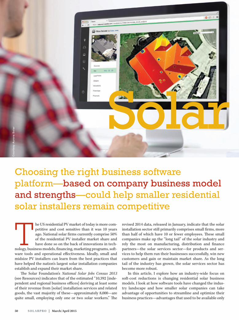
50 S O L A R PR O | March/April 2015
The US residential PV market of today is more com-petitive and cost sensitive than it was 10 years ago. National solar firms currently comprise 50% of the residential PV installer market share and have done so on the back of innovations in tech-
nology, business models, financing, marketing programs, soft-ware tools and operational effectiveness. Ideally, small and midsize PV installers can learn from the best practices that have helped the nation’s largest solar installation companies establish and expand their market share.
The Solar Foundation’s National Solar Jobs Census 2013 (see Resources) indicates that of the estimated “10,392 [inde-pendent and regional business offices] deriving at least some of their revenue from [solar] installation services and related goods, the vast majority of these—approximately 8,000—are quite small, employing only one or two solar workers.” The
revised 2014 data, released in January, indicate that the solar installation sector still primarily comprises small firms, more than half of which have 10 or fewer employees. These small companies make up the “long tail” of the solar industry and rely the most on manufacturing, distribution and finance partners—the solar services sector—for products and ser-vices to help them run their businesses successfully, win new customers and gain or maintain market share. As the long tail of the industry has grown, the solar services sector has become more robust.
In this article, I explore how an industry-wide focus on soft-cost reductions is changing residential solar business models. I look at how software tools have changed the indus-try landscape and how smaller solar companies can take advantage of opportunities to streamline and optimize their business practices—advantages that used to be available only
Choosing the right business software platform—based on company business model and strengths—could help smaller residential solar installers remain competitive
Solar Business
Co
urt
es
y A
uro
ra S
ola
r

solarprofessional.com | S O L A R PR O 51
to larger national firms. I conclude with an overview of several solar business software platforms that can help residential installation companies automate routine business processes and focus their resources on providing quality customer ser-vice and installing quality PV systems. For the purposes of this article, I define a solar business platform as a stand-alone or cloud-based software tool that not only automates core sales activities, such as proposal generation and system design, but also tracks and streamlines some combination of pre- and post-sales activities, such as lead generation and manage-ment, business administration and project management.
Residential Solar Growth Of all the solar market sectors, residential solar has expe-rienced the steadiest growth since 2008. This rising tide may not float all boats equally. According to US PV Leader-board data published by GTM Research in October 2014 (see Resources), SolarCity and Vivint Solar accounted for 51% of the residential market share in Q2 2014. From Q1 to Q2 2014, SolarCity increased its US residential market share from 28% to 36%, while Vivint Solar nearly doubled its market share to 15%. However, other data indicate that the overall residen-tial market continues to grow, even as the largest installation companies post larger and larger numbers.
Nevertheless, the residential sector is clearly undergoing meaningful changes. According to the “US Solar Market Insight
Report 2014 Q3” (see Resources), published by the Solar Energy Industries Association (SEIA) and GTM Research, “For the first time ever, more than 300 MWdc of residential PV came on line in a single quarter and more than 50% [of] residential PV came on line without any state incentive” (emphasis added). The report notes that while third-party ownership rates are still on the rise in markets such as New York and New Jersey, they are flattening out and even decreasing in other important markets, including Arizona and California.
According to the report, there are two main reasons for decreasing third-party ownership rates. First, more and more installers are able to offer loans to their customers. Second, customers are increasingly able to make cash pur-chases due to steadily declining PV system prices. This latter trend is particularly notable, as PV module prices were gen-erally flat in 2014 and have actually increased since late 2013. Instead, nonhardware BOS cost reductions largely drove the recent PV system price declines, in part due to increases in operational efficiency.
Soft-Cost OpportunityReducing business process or nonhardware BOS costs—often referred to as soft costs—creates a major opportunity for the solar industry to open new markets. To accelerate cus-tomer adoption in sectors with low electric rates or without
By Pamela Cargill
Solar BusinessSoftware Platforms
Residential
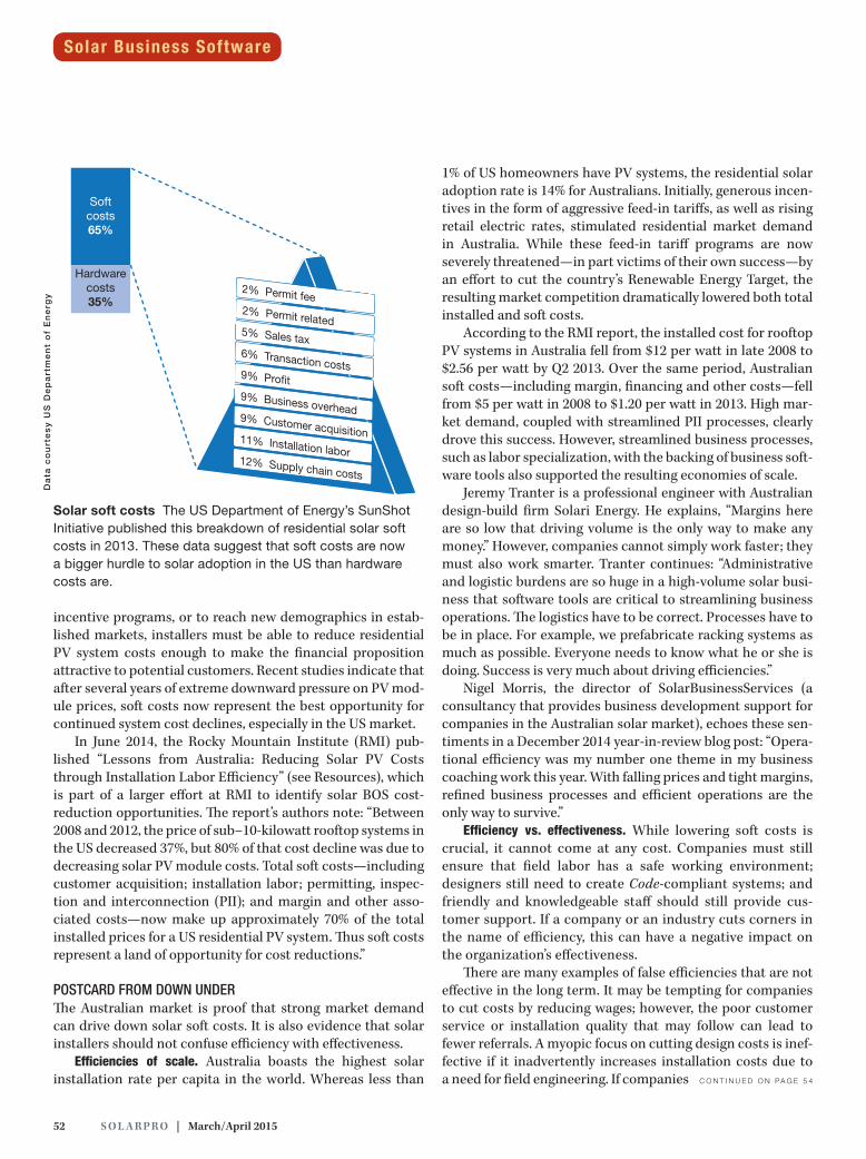
52 S O L A R PR O | March/April 2015
incentive programs, or to reach new demographics in estab-lished markets, installers must be able to reduce residential PV system costs enough to make the financial proposition attractive to potential customers. Recent studies indicate that after several years of extreme downward pressure on PV mod-ule prices, soft costs now represent the best opportunity for continued system cost declines, especially in the US market.
In June 2014, the Rocky Mountain Institute (RMI) pub-lished “Lessons from Australia: Reducing Solar PV Costs through Installation Labor Efficiency” (see Resources), which is part of a larger effort at RMI to identify solar BOS cost-reduction opportunities. The report’s authors note: “Between 2008 and 2012, the price of sub–10-kilowatt rooftop systems in the US decreased 37%, but 80% of that cost decline was due to decreasing solar PV module costs. Total soft costs—including customer acquisition; installation labor; permitting, inspec-tion and interconnection (PII); and margin and other asso-ciated costs—now make up approximately 70% of the total installed prices for a US residential PV system. Thus soft costs represent a land of opportunity for cost reductions.”
POSTCARD FROM DOWN UNDER The Australian market is proof that strong market demand can drive down solar soft costs. It is also evidence that solar installers should not confuse efficiency with effectiveness.
Efficiencies of scale. Australia boasts the highest solar installation rate per capita in the world. Whereas less than
1% of US homeowners have PV systems, the residential solar adoption rate is 14% for Australians. Initially, generous incen-tives in the form of aggressive feed-in tariffs, as well as rising retail electric rates, stimulated residential market demand in Australia. While these feed-in tariff programs are now severely threatened—in part victims of their own success—by an effort to cut the country’s Renewable Energy Target, the resulting market competition dramatically lowered both total installed and soft costs.
According to the RMI report, the installed cost for rooftop PV systems in Australia fell from $12 per watt in late 2008 to $2.56 per watt by Q2 2013. Over the same period, Australian soft costs—including margin, financing and other costs—fell from $5 per watt in 2008 to $1.20 per watt in 2013. High mar-ket demand, coupled with streamlined PII processes, clearly drove this success. However, streamlined business processes, such as labor specialization, with the backing of business soft-ware tools also supported the resulting economies of scale.
Jeremy Tranter is a professional engineer with Australian design-build firm Solari Energy. He explains, “Margins here are so low that driving volume is the only way to make any money.” However, companies cannot simply work faster; they must also work smarter. Tranter continues: “Administrative and logistic burdens are so huge in a high-volume solar busi-ness that software tools are critical to streamlining business operations. The logistics have to be correct. Processes have to be in place. For example, we prefabricate racking systems as much as possible. Everyone needs to know what he or she is doing. Success is very much about driving efficiencies.”
Nigel Morris, the director of SolarBusinessServices (a consultancy that provides business development support for companies in the Australian solar market), echoes these sen-timents in a December 2014 year-in-review blog post: “Opera-tional efficiency was my number one theme in my business coaching work this year. With falling prices and tight margins, refined business processes and efficient operations are the only way to survive.”
Efficiency vs. effectiveness. While lowering soft costs is crucial, it cannot come at any cost. Companies must still ensure that field labor has a safe working environment; designers still need to create Code-compliant systems; and friendly and knowledgeable staff should still provide cus-tomer support. If a company or an industry cuts corners in the name of efficiency, this can have a negative impact on the organization’s effectiveness.
There are many examples of false efficiencies that are not effective in the long term. It may be tempting for companies to cut costs by reducing wages; however, the poor customer service or installation quality that may follow can lead to fewer referrals. A myopic focus on cutting design costs is inef-fective if it inadvertently increases installation costs due to a need for field engineering. If companies C O N T I N U E D O N PA G E 5 4
Solar Business SoftwareD
ata
co
urt
es
y U
S D
ep
art
me
nt
of
En
erg
y
Solar soft costs The US Department of Energy’s SunShot Initiative published this breakdown of residential solar soft costs in 2013. These data suggest that soft costs are now a bigger hurdle to solar adoption in the US than hardware costs are.
Softcosts65%
Hardwarecosts35%
download our FREE quick-quote app in the Apple Store
,
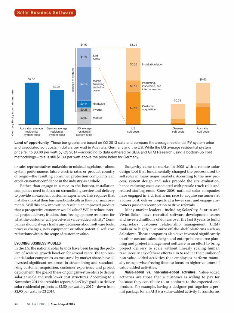
54 S O L A R PR O | March/April 2015
Co
urt
es
y R
oc
ky
Mo
un
tain
In
sti
tute
or sales representatives make false or misleading claims—about system performance, future electric rates or product country of origin—the resulting consumer protection complaints can erode customer confidence in the industry as a whole.
Rather than engage in a race to the bottom, installation companies need to focus on streamlining service and delivery to provide an excellent customer experience. This requires that installers look at their business holistically as they plan improve-ments. Will this new innovation result in an improved product that a prospective customer would value? Will it reduce inter-nal project delivery friction, thus freeing up more resources for what the customer will perceive as value-added activity? Com-panies should always frame any decisions about software tools, process changes, new equipment or other potential soft cost reductions within the scope of customer value.
EVOLVING BUSINESS MODELS In the US, the national solar brands have been facing the prob-lem of scalable growth head-on for several years. The top resi-dential solar companies, as measured by market share, have all invested significant resources in streamlining and standard-izing customer acquisition, customer experience and project deployment. The goal of these ongoing investments is to deliver solar at scale and with lower cost structures. According to a November 2014 shareholder report, SolarCity’s goal is to deliver solar residential projects at $2.50 per watt by 2017—down from $2.90 per watt in Q3 2014.
Sungevity came to market in 2008 with a remote solar design tool that fundamentally changed the process used to sell solar in many major markets. According to the new pro-cess, system design and sales precede the site evaluation, hence reducing costs associated with presale truck rolls and related staffing costs. Since 2008, national solar companies have engaged in a virtual arms race to acquire customers at a lower cost, deliver projects at a lower cost and engage cus-tomers post-interconnection to drive referrals.
Many market leaders—including SolarCity, Sunrun and Vivint Solar—have recruited software development teams and invested millions of dollars over the last 5 years to build proprietary customer relationship management (CRM) tools or to highly customize off-the-shelf platforms such as Salesforce. These companies also have invested significantly in other custom sales, design and enterprise resource plan-ning and project management software in an effort to bring project delivery to scale without linearly scaling human resources. Many of these efforts aim to reduce the number of non-value-added activities that employees perform manu-ally or supervise, freeing them to focus on higher volumes of value-added activities.
Value-added vs. non-value-added activities. Value-added activities are those that a customer is willing to pay for because they contribute to or conform to the expected end product. For example, having a designer put together a per-mit package for an AHJ is a value-added activity. It transforms
Australian average residential
system price
USsoft costs
German averageresidential
system price
US averageresidential
system price
German soft costs
Australian soft costs
$2.56
$2.21
$0.65
$0.33
Installation labor
Permitting,inspection, and interconnection
Customeracquisition
Softcosts
$4.93
$1.22
$2.16
$0.44
$0.28
$0.83
$1.22
$0.55
$0.19
$0.48
Margin�nancingand othercosts
Hardware
Module
Inverter
Bal
ance
of s
yste
ms
Land of opportunity These bar graphs are based on Q2 2013 data and compare the average residential PV system price and associated soft costs in dollars per watt in Australia, Germany and the US. While the US average residential system price fell to $3.60 per watt by Q3 2014—according to data gathered by SEIA and GTM Research using a bottom-up cost methodology—this is still $1.39 per watt above the price index for Germany.
Solar Business Software
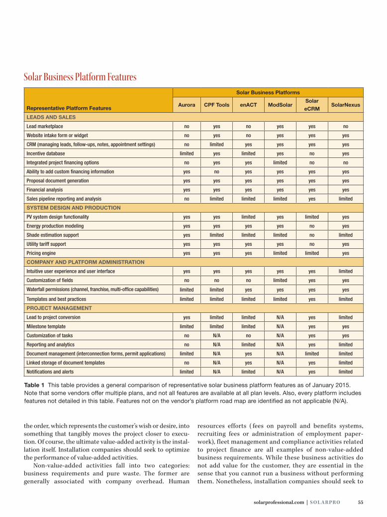
solarprofessional.com | S O L A R PR O 55
Representative Platform Features
Solar Business Platforms
Aurora CPF Tools enACT ModSolarSolar
eCRMSolarNexus
LEADS AND SALES
Lead marketplace no yes no yes yes no
Website intake form or widget no yes no yes yes yes
CRM (managing leads, follow-ups, notes, appointment settings) no limited yes yes yes yes
Incentive database limited yes limited yes no yes
Integrated project financing options no yes yes limited no no
Ability to add custom financing information yes no yes yes yes yes
Proposal document generation yes yes yes yes yes yes
Financial analysis yes yes yes yes yes yes
Sales pipeline reporting and analysis no limited limited limited yes limited
SYSTEM DESIGN AND PRODUCTION
PV system design functionality yes yes limited yes limited yes
Energy production modeling yes yes yes yes no yes
Shade estimation support yes limited limited limited no limited
Utility tariff support yes yes yes yes no yes
Pricing engine yes yes yes limited limited yes
COMPANY AND PLATFORM ADMINISTRATION
Intuitive user experience and user interface yes yes yes yes yes limited
Customization of fields no no no limited yes yes
Waterfall permissions (channel, franchise, multi-office capabilities) limited limited yes yes yes yes
Templates and best practices limited limited limited limited yes limited
PROJECT MANAGEMENT
Lead to project conversion yes limited limited N/A yes limited
Milestone template limited limited limited N/A yes yes
Customization of tasks no N/A no N/A yes yes
Reporting and analytics no N/A limited N/A yes limited
Document management (interconnection forms, permit applications) limited N/A yes N/A limited limited
Linked storage of document templates no N/A yes N/A yes limited
Notifications and alerts limited N/A limited N/A yes limited
Table 1 This table provides a general comparison of representative solar business platform features as of January 2015. Note that some vendors offer multiple plans, and not all features are available at all plan levels. Also, every platform includes features not detailed in this table. Features not on the vendor’s platform road map are identified as not applicable (N/A).
Solar Business Platform Features
the order, which represents the customer’s wish or desire, into something that tangibly moves the project closer to execu-tion. Of course, the ultimate value-added activity is the instal-lation itself. Installation companies should seek to optimize the performance of value-added activities.
Non-value-added activities fall into two categories: business requirements and pure waste. The former are generally associated with company overhead. Human
resources efforts ( fees on payroll and benefits systems, recruiting fees or administration of employment paper-work), fleet management and compliance activities related to project finance are all examples of non-value-added business requirements. While these business activities do not add value for the customer, they are essential in the sense that you cannot run a business without performing them. Nonetheless, installation companies should seek to

56 S O L A R PR O | March/April 2015
minimize or automate these non-value-added business activities as much as possible.
Other activities not only provide no value to the customer, but also offer no value to the business. Holding excessive coor-dination meetings, generating reports that go unread, creating policies that go unenforced, having multiple internal layers of approval and doing any kind of rework are all examples of pure waste. Installation companies should always seek to eliminate activities in this category.
Solar Business PlatformsToday’s solar installation companies have many more choices in how to set up and run their business than the pioneering firms had 10 or more years ago. Early solar contractors had to master system design and installation for multiple tech-nologies—on- and off-grid PV systems, solar thermal or pool heating systems, small wind or microhydro turbines, green building and home efficiency solutions. They also had to pos-sess some sales and marketing savvy, and understand the business of construction. As a result, the market presented a high barrier of entry.
Now, solar installation companies can segment and spe-cialize their businesses—not just by technology or applica-tion, but also by selectively outsourcing activities that do not suit their core strengths. In the past, a small installation
company generally had to scale every aspect of its business linearly to grow. This is no longer the case. Companies can outsource lead generation, marketing programs, back-office paperwork prepara-tion and design services, as well as traditional construction-related subcontracting activities. In fact, labor constraints related to spe-cialized content areas—such as PV system design expertise—have spurred growth opportunities for outsourced solar business ser-vices. In highly competitive solar markets, such as the San Francisco Bay Area, knowledgeable designers are hard to find and can fetch a sal-ary premium.
Until relatively recently, solar installation companies that were unable to build their own custom software tools were primarily lim-ited to platforms focused on pre-sales activities such as proposal
generation and financial benefit analysis. For example, OnGrid Solar launched its spreadsheet-based software tool in 2005, which allowed for more sophisticated and nuanced solar sales proposals. OnGrid’s software not only allows users to gener-ate proposals at a prospective customer’s kitchen table, but also combines powerful financial analysis capabilities with an extensive rate structure database. This means users can quickly model the impact of varying PV system capacities ver-sus the utility rate structure and hone in on the system design and utility tariff that provide the most value to the customer. Since then, several vendors have brought web-based solar business platforms to market that expand on these proposal and financial analysis capabilities. Installation companies can now automate or streamline most aspects of the sales cycle, design process, project financing and delivery.
PRODUCT OVERVIEWIn this section, I review six of the available solar business platforms and describe how installation companies can best leverage each of these platforms to compliment their unique business model and market dynamics. In each of the overviews, I provide a brief company background, detail defining software features, describe the user interface, summarize unique prod-uct strengths and suggest a profile of the type of solar installa-tion company most likely to benefit from using the tool.
Each of these solar business platforms has different sets of features, as illustrated in Table 1 (p. 55). Sales features include
Process optimization Installation companies can use business software platforms to optimize the execution of a variety of value-added activities. For example, Aurora Solar’s cloud-based platform can automatically generate single-line drawings for permit packages.
Co
urt
es
y A
uro
ra S
ola
rSolar Business Software
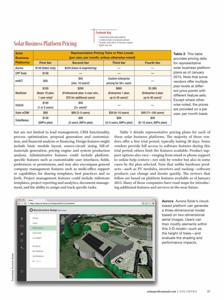
solarprofessional.com | S O L A R PR O 57
but are not limited to lead management, CRM functionality, process optimization, proposal generation and customiza-tion, and financial analysis or financing. Design features might include basic module layout, source-circuit sizing, bill-of- materials generation, pricing engine and system production analysis. Administrative features could include platform-specific features such as customizable user interfaces, fields, preferences or permissions, and may also encompass general company management features such as multi-office support or capabilities for sharing templates, best practices and so forth. Project management features could include milestone templates, project reporting and analytics, document manage-ment, and the ability to assign and track specific tasks.
Table 2 details representative pricing plans for each of these solar business platforms. The majority of these ven-dors offer a free trial period, typically lasting 30 days. Some vendors provide full access to software features during this trial period; others limit the features available. Product sup-port options also vary—ranging from email or phone support to online help centers—not only by vendor but also in some cases by the plan selected. Note that unlike hardware prod-ucts—such as PV modules, inverters and racking—software products can change and iterate quickly. The reviews that follow are based on platform features available as of January 2015. Many of these companies have road maps for introduc-ing additional features and services in the near future.
Co
urt
es
y A
uro
ra S
ola
r
Solar
Business
Platforms
Representative Pricing Tiers or Plan Levels
(per user, per month, unless otherwise noted)
First tier Second tier Third tier Fourth tier
Aurora $159 (Sales only) $259 (Sales & engineering) — —
CPF Tools $139 — — —
enACT $50$50
(min. 10 users)1
Custom enterprise
pricing for 50+ users—
ModSolar
$100
(Basic 10 plan:
1 user only)2
$295
(Professional plan: 3-user min.,
$70 for additional users)
$995
(Enterprise 1 plan:
up to 20 users)3
$1,995
(Enterprise 2 plan:
up to 40 users)3
OnGrid$100
(1 or 2 users)
$50
(3+ users)4— —
Solar eCRM $89 $69 (2–5 users) $59 (6–10 users) $49 (11–100 users)
SolarNexus $139
(AllPro plan)
$99
(2 users, AllPro plan)
$69
(3–5 users, AllPro plan)
$59
(6–10 users, AllPro plan)
Table 2 This table provides pricing data for representative solar business platform plans as of January 2015. Note that some vendors offer multiple plan levels at differ-ent price points with different feature sets. Except where other-wise noted, the prices are provided on a per user, per month basis.
Solar Business Platform Pricing1 Customized white-label platform2 Limited number of proposals allowed3 Includes multi-office or franchise support 4 Eighth user free
Aurora Aurora Solar’s cloud-based platform can generate a three-dimensional model based on two-dimensional aerial images. Users can then modify elements within this 3-D model—such as the height of trees—and evaluate the shading and performance impacts.
Footnote Key
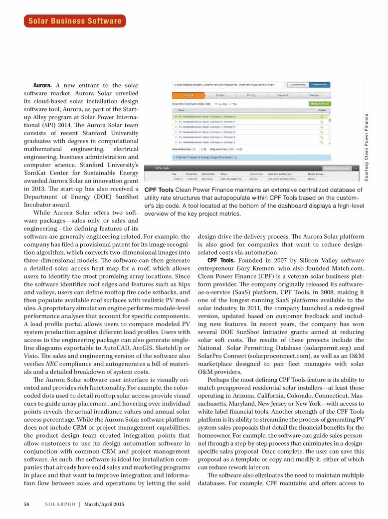
58 S O L A R PR O | March/April 2015
Aurora. A new entrant to the solar software market, Aurora Solar unveiled its cloud-based solar installation design software tool, Aurora, as part of the Start-up Alley program at Solar Power Interna-tional (SPI) 2014. The Aurora Solar team consists of recent Stanford University graduates with degrees in computational mathematical engineering, electrical engineering, business administration and computer science. Stanford University’s TomKat Center for Sustainable Energy awarded Aurora Solar an innovation grant in 2013. The start-up has also received a Department of Energy (DOE) SunShot Incubator award.
While Aurora Solar offers two soft-ware packages—sales only, or sales and engineering—the defining features of its software are generally engineering related. For example, the company has filed a provisional patent for its image recogni-tion algorithm, which converts two-dimensional images into three-dimensional models. The software can then generate a detailed solar access heat map for a roof, which allows users to identify the most promising array locations. Since the software identifies roof edges and features such as hips and valleys, users can define rooftop fire code setbacks, and then populate available roof surfaces with realistic PV mod-ules. A proprietary simulation engine performs module-level performance analyses that account for specific components. A load profile portal allows users to compare modeled PV system production against different load profiles. Users with access to the engineering package can also generate single-line diagrams exportable to AutoCAD, ArcGIS, SketchUp or Visio. The sales and engineering version of the software also verifies NEC compliance and autogenerates a bill of materi-als and a detailed breakdown of system costs.
The Aurora Solar software user interface is visually ori-ented and provides rich functionality. For example, the color-coded dots used to detail rooftop solar access provide visual cues to guide array placement, and hovering over individual points reveals the actual irradiance values and annual solar access percentage. While the Aurora Solar software platform does not include CRM or project management capabilities, the product design team created integration points that allow customers to use its design automation software in conjunction with common CRM and project management software. As such, the software is ideal for installation com-panies that already have solid sales and marketing programs in place and that want to improve integration and informa-tion flow between sales and operations by letting the sold
design drive the delivery process. The Aurora Solar platform is also good for companies that want to reduce design-related costs via automation.
CPF Tools. Founded in 2007 by Silicon Valley software entrepreneur Gary Kremen, who also founded Match.com, Clean Power Finance (CPF) is a veteran solar business plat-form provider. The company originally released its software- as-a-service (SaaS) platform, CPF Tools, in 2008, making it one of the longest-running SaaS platforms available to the solar industry. In 2011, the company launched a redesigned version, updated based on customer feedback and includ-ing new features. In recent years, the company has won several DOE SunShot Initiative grants aimed at reducing solar soft costs. The results of these projects include the National Solar Permitting Database (solarpermit.org) and SolarPro Connect (solarproconnect.com), as well as an O&M marketplace designed to pair fleet managers with solar O&M providers.
Perhaps the most defining CPF Tools feature is its ability to match preapproved residential solar installers—at least those operating in Arizona, California, Colorado, Connecticut, Mas-sachusetts, Maryland, New Jersey or New York—with access to white-label financial tools. Another strength of the CPF Tools platform is its ability to streamline the process of generating PV system sales proposals that detail the financial benefits for the homeowner. For example, the software can guide sales person-nel through a step-by-step process that culminates in a design-specific sales proposal. Once complete, the user can save this proposal as a template or copy and modify it, either of which can reduce rework later on.
The software also eliminates the need to maintain multiple databases. For example, CPF maintains and offers access to
Co
urt
es
y C
lea
n P
ow
er
Fin
an
ce
CPF Tools Clean Power Finance maintains an extensive centralized database of utility rate structures that autopopulate within CPF Tools based on the custom-er’s zip code. A tool located at the bottom of the dashboard displays a high-level overview of the key project metrics.
Solar Business Software
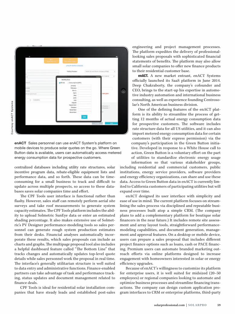
solarprofessional.com | S O L A R PR O 59
Co
urt
es
y e
nA
CT
Sy
ste
ms
centralized databases including utility rate structures, solar incentive program data, rebate-eligible equipment lists and performance data, and so forth. These data can be time- consuming for a small business to track and difficult to update across multiple prospects, so access to these data-bases saves solar companies time and effort.
The CPF Tools user interface is functional rather than flashy. However, sales staff can remotely perform aerial site surveys and take roof measurements to generate system capacity estimates. The CPF Tools platform includes the abil-ity to upload Solmetric SunEye data or enter an estimated shading percentage. It also makes extensive use of Solmet-ric’s PV Designer performance-modeling tools so sales per-sonnel can generate rough system production estimates from their desks. Financial analyses automatically incor-porate these results, which sales proposals can include as charts and graphs. The multipage proposal tool also includes a helpful dashboard feature called “The Bottom Line” that tracks changes and automatically updates top-level quote details while sales personnel work the proposal in real time. The interface’s generally utilitarian structure is well suited to data entry and administrative functions. Finance-enabled partners can take advantage of task and performance track-ing, status updates and document management related to finance deals.
CPF Tools is ideal for residential solar installation com-panies that have steady leads and established post-sales
engineering and project management processes. The platform expedites the delivery of professional-looking sales proposals with sophisticated financial statements of benefits. The platform may also allow small solar companies to offer new finance products to their residential customer base.
enACT. A new market entrant, enACT Systems officially launched its SaaS platform in June 2014. Deep Chakraborty, the company’s cofounder and CEO, brings to the start-up his expertise in automo-tive industry automation and international business consulting, as well as experience founding Centroso-lar’s North American business division.
One of the defining features of the enACT plat-form is its ability to streamline the process of get-ting 12 months of actual energy consumption data for prospective customers. The software includes rate structure data for all US utilities, and it can also import metered energy consumption data for certain customers (with their express permission) via the
company’s participation in the Green Button initia-tive. Developed in response to a White House call to action, Green Button is a voluntary effort on the part of utilities to standardize electronic energy usage information so that various stakeholder groups,
including residential and commercial customers, public institutions, energy service providers, software providers and energy efficiency organizations, can share and use these data. Access to Green Button data in enACT is currently lim-ited to California customers of participating utilities but will expand over time.
enACT designed its user interface with simplicity and ease of use in mind. The current platform focuses on stream-lining the sales process via disciplined and repeatable busi-ness processes built atop a simple CRM. (The company plans to add a complementary platform for boutique solar financers in the near future.) It includes remote site assess-ment and array layout tools, straightforward performance- modeling capabilities, and document generation, manage-ment and approval features. On a desktop or mobile device, users can prepare a sales proposal that includes different project finance options such as loans, cash or PACE financ-ing. Premium users can automate branded marketing out-reach efforts via online platforms designed to increase engagement with homeowners interested in solar or energy efficiency upgrades.
Because of enACT’s willingness to customize its platform for enterprise users, it is well suited for midsized (20–50 employees) or regional companies looking to automate and optimize business processes and streamline financing trans-actions. The company can design custom application pro-gram interfaces to CRM or enterprise platforms, third-party
enACT Sales personnel can use enACT System’s platform on mobile devices to produce solar quotes on the go. Where Green Button data is available, users can automatically access metered energy consumption data for prospective customers.
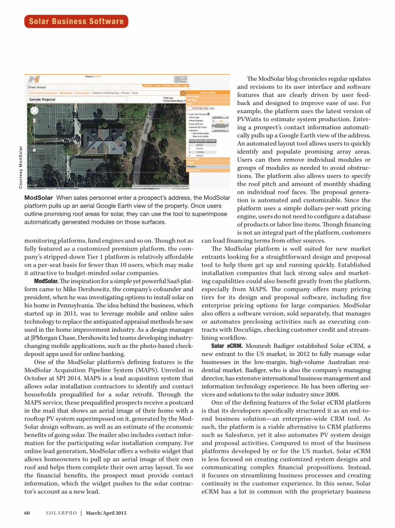
60 S O L A R PR O | March/April 2015
monitoring platforms, fund engines and so on. Though not as fully featured as a customized premium platform, the com-pany’s stripped-down Tier 1 platform is relatively affordable on a per-seat basis for fewer than 10 users, which may make it attractive to budget-minded solar companies.
ModSolar. The inspiration for a simple yet powerful SaaS plat-form came to Mike Dershowitz, the company’s cofounder and president, when he was investigating options to install solar on his home in Pennsylvania. The idea behind the business, which started up in 2011, was to leverage mobile and online sales technology to replace the antiquated appraisal methods he saw used in the home improvement industry. As a design manager at JPMorgan Chase, Dershowitz led teams developing industry-changing mobile applications, such as the photo-based check-deposit apps used for online banking.
One of the ModSolar platform’s defining features is the ModSolar Acquisition Pipeline System (MAPS). Unveiled in October at SPI 2014, MAPS is a lead acquisition system that allows solar installation contractors to identify and contact households prequalified for a solar retrofit. Through the MAPS service, these prequalified prospects receive a postcard in the mail that shows an aerial image of their home with a rooftop PV system superimposed on it, generated by the Mod-Solar design software, as well as an estimate of the economic benefits of going solar. The mailer also includes contact infor-mation for the participating solar installation company. For online lead generation, ModSolar offers a website widget that allows homeowners to pull up an aerial image of their own roof and helps them complete their own array layout. To see the financial benefits, the prospect must provide contact information, which the widget pushes to the solar contrac-tor’s account as a new lead.
The ModSolar blog chronicles regular updates and revisions to its user interface and software features that are clearly driven by user feed-back and designed to improve ease of use. For example, the platform uses the latest version of PVWatts to estimate system production. Enter-ing a prospect’s contact information automati-cally pulls up a Google Earth view of the address. An automated layout tool allows users to quickly identify and populate promising array areas. Users can then remove individual modules or groups of modules as needed to avoid obstruc-tions. The platform also allows users to specify the roof pitch and amount of monthly shading on individual roof faces. The proposal genera-tion is automated and customizable. Since the platform uses a simple dollars-per-watt pricing engine, users do not need to configure a database of products or labor line items. Though financing is not an integral part of the platform, customers
can load financing terms from other sources. The ModSolar platform is well suited for new market
entrants looking for a straightforward design and proposal tool to help them get up and running quickly. Established installation companies that lack strong sales and market-ing capabilities could also benefit greatly from the platform, especially from MAPS. The company offers many pricing tiers for its design and proposal software, including five enterprise pricing options for large companies. ModSolar also offers a software version, sold separately, that manages or automates preclosing activities such as executing con-tracts with DocuSign, checking customer credit and stream-lining workflow.
Solar eCRM. Mounesh Badiger established Solar eCRM, a new entrant to the US market, in 2012 to fully manage solar businesses in the low-margin, high-volume Australian resi-dential market. Badiger, who is also the company’s managing director, has extensive international business management and information technology experience. He has been offering ser-vices and solutions to the solar industry since 2008.
One of the defining features of the Solar eCRM platform is that its developers specifically structured it as an end-to-end business solution—an enterprise-wide CRM tool. As such, the platform is a viable alternative to CRM platforms such as Salesforce, yet it also automates PV system design and proposal activities. Compared to most of the business platforms developed by or for the US market, Solar eCRM is less focused on creating customized system designs and communicating complex financial propositions. Instead, it focuses on streamlining business processes and creating continuity in the customer experience. In this sense, Solar eCRM has a lot in common with the proprietary business
Co
urt
es
y M
od
So
lar
ModSolar When sales personnel enter a prospect’s address, the ModSolar platform pulls up an aerial Google Earth view of the property. Once users outline promising roof areas for solar, they can use the tool to superimpose automatically generated modules on those surfaces.
Solar Business Software
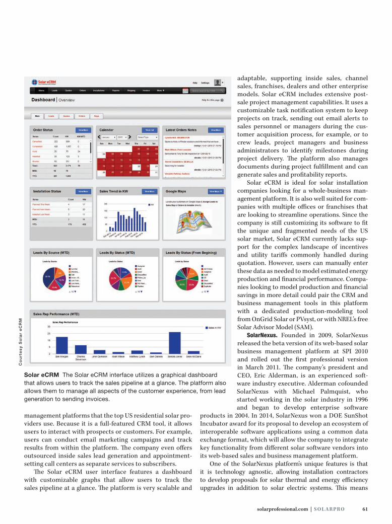
solarprofessional.com | S O L A R PR O 61
management platforms that the top US residential solar pro-viders use. Because it is a full-featured CRM tool, it allows users to interact with prospects or customers. For example, users can conduct email marketing campaigns and track results from within the platform. The company even offers outsourced inside sales lead generation and appointment-setting call centers as separate services to subscribers.
The Solar eCRM user interface features a dashboard with customizable graphs that allow users to track the sales pipeline at a glance. The platform is very scalable and
adaptable, supporting inside sales, channel sales, franchises, dealers and other enterprise models. Solar eCRM includes extensive post-sale project management capabilities. It uses a customizable task notification system to keep projects on track, sending out email alerts to sales personnel or managers during the cus-tomer acquisition process, for example, or to crew leads, project managers and business administrators to identify milestones during project delivery. The platform also manages documents during project fulfillment and can generate sales and profitability reports.
Solar eCRM is ideal for solar installation companies looking for a whole-business man-agement platform. It is also well suited for com-panies with multiple offices or franchises that are looking to streamline operations. Since the company is still customizing its software to fit the unique and fragmented needs of the US solar market, Solar eCRM currently lacks sup-port for the complex landscape of incentives and utility tariffs commonly handled during quotation. However, users can manually enter these data as needed to model estimated energy production and financial performance. Compa-nies looking to model production and financial savings in more detail could pair the CRM and business management tools in this platform with a dedicated production-modeling tool from OnGrid Solar or PVsyst, or with NREL’s free Solar Advisor Model (SAM).
SolarNexus. Founded in 2009, SolarNexus released the beta version of its web-based solar business management platform at SPI 2010 and rolled out the first professional version in March 2011. The company’s president and CEO, Eric Alderman, is an experienced soft-ware industry executive. Alderman cofounded SolarNexus with Michael Palmquist, who started working in the solar industry in 1996 and began to develop enterprise software
products in 2004. In 2014, SolarNexus won a DOE SunShot Incubator award for its proposal to develop an ecosystem of interoperable software applications using a common data exchange format, which will allow the company to integrate key functionality from different solar software vendors into its web-based sales and business management platform.
One of the SolarNexus platform’s unique features is that it is technology agnostic, allowing installation contractors to develop proposals for solar thermal and energy efficiency upgrades in addition to solar electric systems. This means
Solar eCRM The Solar eCRM interface utilizes a graphical dashboard that allows users to track the sales pipeline at a glance. The platform also allows them to manage all aspects of the customer experience, from lead generation to sending invoices.
Co
urt
es
y S
ola
r e
CR
M

62 S O L A R PR O | March/April 2015
installation contractors can simultaneously estimate costs, model performance and provide a quote for multiple solutions. The solar thermal functionality allows users to model complete solar hot water systems much as they can model PV system per-formance. Users can also specify the expected energy savings associated with proposed efficiency upgrades, and the applica-tion accounts for these in the project’s financial analyses.
At SPI 2014, SolarNexus launched a new and improved user interface that allows for a more visually based design process. Via its SunShot-supported project, SolarNexus has integrated key SolarDesignTool capabilities, most notably a lightweight Google Maps–based array layout tool. Design results, including equipment selection and production esti-mates, flow back into the proposal generation screens. At the core of SolarNexus is a robust, flexible pricing engine. This was originally conceived as a way for distributors and OEMs to upload and update their product catalogue and pricing. However, most installation contractors use this to manage product data from across their supply chain. A waterfall set of permissions allows managers to change or push out new pricing, equipment or templates to all users. After the sale, installers can set up a custom milestone, task and depen-dency system to help shepherd the project to completion. SolarNexus includes a simple tabular reporting system, and can export data for further slicing and dicing in a spreadsheet.
Companies looking for a fully customizable business platform will find SolarNexus attractive. It is well suited for power users or hands-on business owners. Administrators have an incredible degree of control within the platform to customize proposal, design and post-sale processes; create
product and utility tariff databases; define margins and milestones; and so on. The platform is also ideal for contrac-tors that offer a suite of services, including solar thermal and home efficiency upgrades.
WHICH PLATFORM IS BEST?There is no one perfect solar business platform. However, some platforms may be better suited to your company’s needs or business model than others. As you evaluate options, reflect on what makes your company unique. What are its strengths and weaknesses? What is its selling style? What will help your managers be more effective?
Overall, a solar business platform should add value to the customer experience, both pre- and post-sale. It should allow you to communicate options to prospects more quickly and accurately. These communications should be easy for cus-tomers to understand and evaluate. A good solar business platform will reduce non-value-added activities and help you optimize value-added ones. If a platform is not doing that, it is not the right tool for you.
Take time to consider the features and benefits of each tool you evaluate. Take advantage of free trials. Review user guides and training videos. Once you make a final decision, redesign your company’s business processes to take advan-tage of the new platform and leverage the unique strengths of your operation.
g C O N T A C T
Pamela Cargill / Chaolysti / Alameda, CA /
[email protected] / chaolysti.com
RESOURCESCalhoun, Koben, et al., “Lessons from Australia: Reducing Solar PV
Costs through Installation Labor Efficiency,” Rocky Mountain Institute,
June 2014
National Solar Jobs Census 2013, The Solar Foundation, February 2014
National Solar Jobs Census 2014, The Solar Foundation, January 2015
“US Solar Market Insight Report 2014 Q3,” SEIA/GTM Research,
December 2014
US PV Leaderboard, GTM Research, October 2014
VENDORSAurora Solar / aurorasolar.com
Clean Power Finance / 866.525.2123 / cleanpowerfinance.com
enACT Systems / 855.503.6228 / enact-systems.com
ModSolar / 610.572.2555 / modsolar.net
OnGrid Solar / 866.966.5577 / ongrid.net
Solar eCRM / 209.920.4988 / solarecrm.com
SolarNexus / 510.842.7875 / solarnexus.com
SolarNexus The SolarNexus platform allows users to define custom milestones, along with dependencies and follow-up actions, and organize these into groups that represent the entire project delivery process.
Co
urt
es
y S
ola
rNe
xu
sSolar Business Software

Exhibit now!
North America’s Premier Exhibition and Conference for the Solar IndustryMoscone Center, San Francisco
The solar hotspot for connecting 17,000 visitors and 550 international exhibitorsMeet the decision makers who are shaping the solar marketIdentify prospects and implement your business strategiesTap into the incredible potential of the U.S. solar marketGo solar at North America's most-attended solar event
Co-located with
AZISNA2015_SolarPro & Home Power_206x276.qxp_Layout 1 26.01.15 10:59 Seite 1

64 S O L A R PR O | March/April 2015
California’s 52-year-old Soiland Company produces rock, soil and
compost products at three locations in Sonoma County, California, and is the North Bay’s largest recycler of rubble materials. When its electric bills nearly tripled overnight due to a new PG&E rate structure, the company enlisted local installer North Coast Solar and Vermont-based dual-axis tracker manu-facturer AllEarth Renewables to design and develop a 202 kWdc tracker farm at its Stony Point Rock Quarry. The system has reduced Soiland’s electricity bills by more than 50 percent and is pro-jected to offset initial equipment and construction costs in approximately 7 years.
The project partners overcame many technical challenges, including the need to run ac transmission lines up the face
of the rock quarry and expansive soils that required the structural engineers to ignore the top 3 feet in their calcula-tions. The pour-in-place foundations for the 33 AllEarth Solar Trackers required 30-inch–diameter, 13-foot-deep piers that are installed on a hillside behind the quarry. The trackers are fully pre-engi-neered, palletized and shipped directly from AllEarth. Installers used a jig to speed the assembly of tracker frames and a telescopic forklift to mount the tracker frames on the mast assemblies.
The site’s original single service was on the PG&E E19 rate schedule and subject to very high demand charges. To optimize project economics, the designers added a second service and developed two separate PV systems. Two services reduced demand below 500 kW and qualified the two smaller
North Coast SolarStony Point Rock Quarry
Co
urt
esy
No
rth
Co
ast
So
lar
(4)
OverviewDESIGNER: Brian Hines, president,
North Coast Solar, ncsr.com
LEAD INSTALLER: Steve Balich, field
superintendent, Lunardi Electric,
lunardielectric.com
DATE COMMISSIONED:
February 1, 2014
INSTALLATION TIME FRAME: 90 days
LOCATION: Cotati, CA, 38.3°N
SOLAR RESOURCE: 5.5 kWh/m2/day
ASHRAE DESIGN TEMPERATURES:
93°F 2% avg. high, 27 °F extreme min.
ARRAY CAPACITY: 202 kWdc
ANNUAL AC PRODUCTION:
439,000 kWh
Projects System Profiles

solarprofessional.com | S O L A R PR O 65
Equipment SpecificationsMODULES: 792 ReneSola JC255M-24/
Bb, 255 W STC, +5/-0 W, 8.39 Imp,
30.4 Vmp, 8.86 Isc, 37.5 Voc
INVERTERS: 3-phase 277/480 Vac
service; 33 SMA America Sunny
Boy 6000-US, 6 kW rated output,
600 Vdc maximum input, 250–480
Vdc MPPT range
ARRAY: 12 modules per source circuit
(3,060 W, 8.39 Imp, 364.8 Vmp, 8.86
Isc, 450 Voc), two source circuits per
inverter (6,120 W, 16.78 Imp, 364.8
Vmp, 17.72 Isc, 450 Voc), 202 kWdc
array total
TRACKERS: 33 Series 24 AllEarth
Solar Trackers, dual-axis GPS-based
array tracking; system includes one
mast-mounted SMA America Sunny
Boy 6000-US inverter and two-circuit
ac load center (for inverter and tracker
controller/motor) per tracker
SYSTEM MONITORING: DECK moni-
toring with CEC-approved revenue
grade metering, AllEarth Renewables
remote monitoring
services for a solar-friendly bundled PG&E A6 time-of-use rate schedule that varies the kWh rate based on time of day and season.
System A serves the quarry’s wet plant and HP400 rock crusher. It is interconnected at the new service and aggregates ac power from 15 Series 24 AllEarth Solar Trackers. System B interconnects the output of 18 Series 24 units at the reconfigured existing ser-vice and supplies power to the quarry’s main plant. Each system has a separate 200 A 480 Vac subpanel. Installers used power poles to route separate 480 V lines down the face of the quarry, where
they interconnect at the site’s main service panel.
Stony Point Rock Quarry’s 202 kWdc array gen-erated an impressive 439,000 ac kWh in its first year due to the Series 24 AllEarth Solar Trackers’ GPS-based dual-axis tracking. In addition, the project’s decentralized inverter design eliminates the possibility of a single point of failure in the power condi-tioning system. It will also
reduce future O&M costs. “As part of this project, we installed
two electric services that qualified the
quarry for a rate schedule that did not
include demand charges, just a bundled
kWh charge. The result is a much more
solar-friendly rate schedule that made the
project economically feasible.”
— Brian Hines, North Coast Solar “The decision to go solar not only made
economic sense, but really aligned with
Soiland’s values. Since the company’s incep-
tion, we have always strived to be sustain-
able and environmentally responsible.”
—Mark Soiland, owner, Soiland Company

As the industry mark of excellence, NABCEP Certification provides you with unparalleled opportunity for job advancement, salary growth and consumer trust. NABCEP Certified professionals are recognized as leaders who are committed to providing exceptional quality and value.
Experience. Quality. Professionalism. Our promise has never changed. And our new look only makes certification more attractive.
Expertise looks good on you.
Fourth AnnualNABCEP Continuing Education ConferenceMarch 30 - April 1, 2015 • Albany NYThis is the ideal opportunity for NABCEP Certified PV Installation Professionals and PV Technical Sales Professionals to obtain all of the continuing education credits needed for recertification. Non-certified professionals can earn up to 18 hours toward certification eligibility. Don’t miss this opportunity to interact with some of the top installation and sales professionals in the country. Details at nabcep.org/ce-2015
PV InstallationProfessional
PV Installation ProfessionalPV Technical Sales Professional
Solar Heating Installer
Now Accepting Applications for Fall 2015 Exams
Visit nabcep.org or call (800) 654-0021
solarprofessional.com | S O L A R PR O 67
Advertiser Index
ABB (Power-One) 3
AEE Solar 13
APS America 14
Array Technologies 35
Backwoods Solar 27
Chint Power Systems IFC
Fronius 7
GameChange Racking 9
HEYCO 37
Ingeteam 45
Intersolar N.A. 2015 63
Magerack 67
Magnum-Dimensions 23
MidNite Solar 67
MREA 43
MT Solar 31
NABCEP CE Conference 66
OMCO Solar 25
OutBack Power 24
PV Labels 49
Quick Mount PV 5
RBI/Renusol 39
Roof Tech 1
Snake Tray 17
SolarBOS 21
SolarEdge IBC
Solectria Renewables BC
Solmetric 15
That Solar Guy 53
Trojan Battery 11
Zomeworks 67
Company Page
$4.50 L-foot and Flashing
$11.40 Tile Hook $11.40$11.40$11.40$11.40$11.40$11.40$11.40$11.40$11.40$11.40$11.40$11.40 Tile HookTile Hook
Patented unique designAbsolute waterproofingEasiest to installLowest cost
$0.12/w Mounting System UL 2703 Listed, Fire Class ‘A’Built-in integrated bondingNo WEEB needed
As low as $0.12 per watt Including L-foot and flashing
Strong and reliable Up to 8 feet rail span
510-656-6661 [email protected] www.magerack.com MAGERACK
MAGERACK SOLAR MOUNTING SYSTEM
$0.12/w Mounting System
Strongest tile hookOnly 0.25” deflection at 452 lb uplift force
Height adjustableOptional flashingDouble flashing to meet building code and roof manufacturer warranty

68 S O L A R PR O | March/April 2015
In the summer of 2014, the Puffer fam-
ily contracted Sunlight Solar Energy to install a 12.9 kW PV system on their residence in Framingham, Massachusetts. To meet the owners’ desire to maximize the overall array size, the company mounted modules in landscape orientation on the house and garage rooftops. Module-level dc optimizers provide design flexibility and optimize energy production.
Since the array size is in excess of 10 kW, Sunlight Solar had to take a number of additional steps and make special considerations during the proj-ect’s design phase, including obtaining special interconnection and AHJ plan review approval, and coordinating all the requirements with the homeowners.
One of the most important consid-erations for this installation was meet-ing the 2014 NEC 690.12 requirements. Sunlight Solar has installed a number of SolarEdge systems for its Massachusetts customers, with general acceptance by the various AHJs. For the Puffer system, the AHJ required additional
documentation and consulta-tion from the manufacturer.
The overall power rating of the system required a line-side point of interconnection. The main distribu-
tion panel (MDP) was already full of con-ductors and OCPDs, so connecting to the service conductors inside that panel was not an option. Sunlight Solar provided a connection box located between the meter and the MDP. Installers rerouted the service conductors from the meter, through the new connection box and then to the MDP. This required a service shutdown to allow the electricians to make the interconnection safely.
“For all our Massachusetts projects, meet-
ing NEC 690.12 is a starting point in our
designs. The first half of 2014 was difficult,
but now we have developed a clean pro-
cess to meet the AHJ requirements. The
Puffer job was a good example of where
doing our homework up front made the
whole process much smoother.”
—Brandon Stephens, director of MA operations, Sunlight Solar Energy
OverviewDESIGNER: Brian Brady, regional
sales manager, Sunlight Solar Energy,
sunlightsolar.com
LEAD INSTALLER: Mike Logan, lead
installer, Sunlight Solar Energy
DATE COMMISSIONED: July 2014
INSTALLATION TIME FRAME: 5 days
LOCATION: Framingham, MA, 42°N
SOLAR RESOURCE: 3.7 kWh/m2/day
ASHRAE DESIGN TEMPERATURES:
90°F 2% avg. high, -4°F extreme min.
ARRAY CAPACITY: 12.9 kWdc
ANNUAL AC PRODUCTION:
13,200 kWh
Equipment SpecificationsMODULES: 47 SolarWorld Sunmodule
Plus SW 275 Mono Black, 275 W STC,
+5/-0 W, 8.94 Imp, 31 Vmp, 9.58 Isc,
39.4 Voc
INVERTERS: 120/240 Vac single-phase
service; one SolarEdge 10000A-US,
10 kW, 500 Vdc maximum input, 350
Vdc nominal input; one SolarEdge
3000A-US, 3 kW, 500 Vdc maximum
input, 350 Vdc nominal input; 47
SolarEdge P300 Power Optimizers, 300
W, 48 Vdc maximum input, 8–48 Vdc
MPPT range
ARRAY: Three source circuits: one 18
module (4,950 W, 350 Vdc nominal), one
17 module (4,675 W, 350 Vdc nominal)
and one 12 module (3,300 W, 350 Vdc
nominal)
ARRAY INSTALLATION: Asphalt shingle
roofing, SnapNrack Series 100 racking,
235° azimuth, 40° tilt
SYSTEM MONITORING:
SolarEdge monitoring with Locus
Energy auto reporter
Sunlight Solar EnergyPuffer Residence
Projects
Co
urt
esy
Su
nlig
ht
So
lar
En
erg
y (2
)


www.solectria.com | [email protected] | 978-683-9700
product offering:
▸ 1Ph Transformerless Inverters (3.8-7.6 kW)
▸ 3Ph Transformerless Inverters (14-28 kW)
▸ 3Ph Central Inverters (50-750 kW)
▸ Utility-Scale Inverters (500 kW-2 MW)
▸ Disconnecting and Arc-Fault Combiners
▸ Web-Based Monitoring
got bankability?
we do.
▸ Subsidiary of Yaskawa, a $4B inverter, motor and automation manufacturer
▸ Backed by 100 Years of Innovation
▸ Broadest Technology Portfolio
▸ Made in the USA