soldier system power integration and … system power integration and field evaluations mr. kailash...
TRANSCRIPT

SOLDIER SYSTEM POWER INTEGRATION AND FIELD EVALUATIONS
Mr. Kailash ShuklaUS Army Natick Soldier RD&E Center
Kansas Street, Bldg 5, Room 118AMSRD-NSR-TP-L
Natick, MA 01760-5000
1. ABSTRACT
The Natick Soldier RD&E Center has been working onmaturing and demonstrating advanced concepts andtechnologies that provide a substantial increase incombat effectiveness for the Small Combat Unitoperating in the Future Force Unit of Action. The paperdescribes the power solutions tested to-date as part ofthese integrated Soldier systems and also discusses somenew power sources planned for demonstration in the nextfew years.
2. INTRODUCTION
The Natick Soldier RD&E Center (NSRDEC) has beenworking on maturing, integrating, and demonstratingadvanced power solutions for modular, openarchitecture, Soldier/Small Combat Unit (SCU) systemof systems that will significantly enhance the combateffectiveness of the SCU operating in the Future ForceUnit of Action. The demonstrations are done throughparticipation in major Army-sponsored experimentations,including (a) U.S. Army Communications-ElectronicsResearch, Development and Engineering Center's(CERDEC) Command, Control, Communications,Computers, Intelligence, Surveillance, andReconnaissance (C4ISR) On the Move (OTM) at FOltDix, N.J., and (b) U.S. Army Training and DoctrineCommand's (TRADOC) Air Assault ExpeditionaryForce (AAEF) Spirals at Fort Benning, Ga. OTM isfocused on the technical and engineering aspects ofestablishing the future force network and making it workin a field environment. AAEF is about exploring how thenetwork enhances operational effectiveness and it alsoprovides the opportunity to experiment with Soldiers inthe field to get feedback on Soldier acceptability of theequipment and to gain insights on the tactical utility ofthe capabilities.
The systems being matured and demonstrated byNSRDEC employ government controlled Modular OpenSystem Architecture (MOSA), focused on current and
future emerging battle command systems, to bring netcentric operations down to the SCU. This relevantsituational awareness information at the Soldier level hashistorically been cumbersome and complicated to obtain.Furthermore, systems developed in the past werecustomized solutions with proprietary restrictions. Usingthe open system design allows new technologies andproducts to be integrated with reduced non-recurringengineering costs. The MOSA approach increases theability of the contractors, vendors, and government teamsto incorporate new technology easily and effectively forthe dismounted Soldier and SCU. The SCU uses Soldierborne system components, supplemental SCUequipment, sensors, robotics, a distributed informationdatabase, and networked communications to executecollective warfighter functions. These systems undergoyearly refinement to ensure the warfighter obtains theright technology by duty position. Optimal distributionof operational capabilities across teams and squads areinvestigated to maximize small unit missionperformance.
3. SYSTEM CONFIGURATIONS TESTEDTO-DATE
An example of the leader system configurationstested to-date is shown in Figure 1. It includes awearable Soldier radio terminal (e.g. WSRT) forcommunication and networking, body worn antenna(BWA) and headgear, global positioning system (GPS), aprocessor, goggle mounted display, precision positionsystem or navigation sub system (PPSINSS), wirelessbody receiver (WBR), a rechargeable lithium-ion battery(e.g. BB-2590) with smart bus (SMBus) capability, azinc-air battery or fuel-cell as mission extender powersources, a Power Manager, a multi-function laser (MFL),a weapon wireless input device (WPN WID) and a hubfor data/power distribution. The leader system alsoincludes mapping and situational awareness software(e.g. Fa1conView) and targeting software (e.g.BareBones) viewed in a goggle-mounted display.

Report Documentation Page Form ApprovedOMB No. 0704-0188
Public reporting burden for the collection of information is estimated to average 1 hour per response, including the time for reviewing instructions, searching existing data sources, gathering andmaintaining the data needed, and completing and reviewing the collection of information. Send comments regarding this burden estimate or any other aspect of this collection of information,including suggestions for reducing this burden, to Washington Headquarters Services, Directorate for Information Operations and Reports, 1215 Jefferson Davis Highway, Suite 1204, ArlingtonVA 22202-4302. Respondents should be aware that notwithstanding any other provision of law, no person shall be subject to a penalty for failing to comply with a collection of information if itdoes not display a currently valid OMB control number.
1. REPORT DATE DEC 2008
2. REPORT TYPE N/A
3. DATES COVERED -
4. TITLE AND SUBTITLE Soldier System Power Integration And Field Evaluations
5a. CONTRACT NUMBER
5b. GRANT NUMBER
5c. PROGRAM ELEMENT NUMBER
6. AUTHOR(S) 5d. PROJECT NUMBER
5e. TASK NUMBER
5f. WORK UNIT NUMBER
7. PERFORMING ORGANIZATION NAME(S) AND ADDRESS(ES) US Army Natick Soldier RD&E Center Kansas Street, Bldg 5, Room 118AMSRD-NSR-TP-L Natick, MA 01760-5000
8. PERFORMING ORGANIZATIONREPORT NUMBER
9. SPONSORING/MONITORING AGENCY NAME(S) AND ADDRESS(ES) 10. SPONSOR/MONITOR’S ACRONYM(S)
11. SPONSOR/MONITOR’S REPORT NUMBER(S)
12. DISTRIBUTION/AVAILABILITY STATEMENT Approved for public release, distribution unlimited
13. SUPPLEMENTARY NOTES See also ADM002187. Proceedings of the Army Science Conference (26th) Held in Orlando, Florida on 1-4December 2008, The original document contains color images.
14. ABSTRACT
15. SUBJECT TERMS
16. SECURITY CLASSIFICATION OF: 17. LIMITATION OF ABSTRACT
SAR
18. NUMBEROF PAGES
4
19a. NAME OFRESPONSIBLE PERSON
a. REPORT unclassified
b. ABSTRACT unclassified
c. THIS PAGE unclassified
Standard Form 298 (Rev. 8-98) Prescribed by ANSI Std Z39-18

G -RCO\ltnk:of'l
PIT-!VoIumo~_o(ii),:
Figure 1. Example of Leader System Configuration
The specific objectives for which the powercomponents were tested are: (1) Compatibility withSoldier equipment - no electromagnetic interferenceissues, correct interfaces and voltages, and compliancewith Smart Management Bus (SM Bus) specifications,(2) Human factors compliance and usability - fits inspace available, switches/connectors/LCD screens areaccessible, and safety issues resolved, and (3) Reliableoperation under various field conditionsvibrationlshockldirt/moisture resistant, operate underenvironmental extremes, and meet performance goals.Some observations from the tests done so far arementioned here. These include: connector issues with theBB-2590 battery due to complex state-of-chargemeasurement; the Zinc-air battery showed potential toincrease the mission runtime if used in parallel with Liion rechargeable battery, however some of the batteriesleaked electrolyte; the direct methanol fuel cell providedthe specified power output and showed increase inruntime, however reliability was poor due toelectromagnetic interference, pump failure, andorientation; and the power manager allowed use of anypower source as input power with high conversionefficiency. In addition, all power components including
2
batteries, fuel cell, and power manager were assessed bySoldiers to be too large and heavy.
Another key Soldier system performance metricmeasured during field experiments related to power andenergy was sustainability of power sources which, asspecified by the Ground Soldier System (GSS)Capability Development Document (CDD), says that thepower source must support autonomous operations for atleast 24 hours (ideally 72 hours) without resupply. Thismetric or requirement, however, is a function of not onlythe energy content of the power sources but also theenergy demand of the power consuming devices, missionactivities of the exercise, and the power managementtechniques employed. Measurement of this sustainmentmetric was done by collecting data on detailed energyusage and power profiles for multiple Soldier systemstested at OTM and AAEF. As expected, energy usagewas affected by duty position, equipment in use, andmission activities of the exercise performed. The leaderpositions for which energy usage was measured includedsquad leader, team leader, platoon leader, and platoonsergeant. The peak power consumption for these leaderpositions was in the range of 50-80 watts. The averagepower consumption for these leader positions varied
Current
from 20-30 watts. The average power consumption forthe rifleman position was in the range of 8-1 0 watts.
4. PATHFORWARD
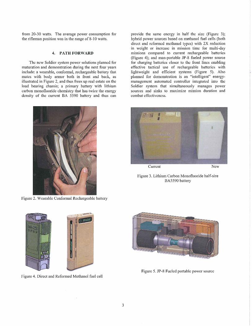
The new Soldier system power solutions planned formaturation and demonstration during the next four yearsinclude: a wearable, conformal, rechargeable battery thatmates with body armor both in front and back, asillustrated in Figure 2, and thus frees up real estate on theload bearing chassis; a primary battery with lithiumcarbon monofluoride chemistry that has twice the energydensity of the current BA 5590 battery and thus can
Figure 2. Wearable Conformal Rechargeable battery
provide the same energy in half the size (Figure 3);hybrid power sources based on methanol fuel cells (bothdirect and reformed methanol types) with 2X reductionin weight or increase in mission time for multi-daymissions compared to current rechargeable batteries(Figure 4); and man-portable JP-8 fueled power sourcefor charging batteries closer to the front lines enablingeffective tactical use of rechargeable batteries withlightweight and efficient systems (Figure 5). Alsoplanned for demonstration is an "intelligent" energymanagement automated controller integrated into theSoldier system that simultaneously manages powersources and sinks to maximize mission duration andcombat effectiveness.
Figure 3. Lithium Carbon Monofluoride half-sizeBA5590 battery
Figure 5. JP-8 Fueled portable power sourceFigure 4. Direct and Reformed Methanol fuel cell
3

REVIEW OF INFORMATION FOR PUBLIC RELEASE
1. AUTHOR: PHONE TEAMIDIR 2. MATERIAL CLASSIFICATION (CHECK ONE):
Kailash Shukla 5313 TSPID ~ UNCL 0 CONF 0 SECRET
3. TYPE OF MATERIAL 0 Website Material 4. FUNDING (identify appropriate category):
0 Natick Technical Report (1096 Attached) 0 Contractor Report (1096 Attached) Direct: 6.3 (e.g., 6.1, 6.2, 6.3, OMA, etc.)
0 Briefing/Presentation 0 Article/Publication(e.g., Marine Corps, Army, AirCustomer:
~ Poster Session 0 Abstract Force, Other 000, etc.)
0 Other Other:
5. TITLE: 6. TYPE OF RELEASE:
SOLDIER SYSTEM POWER INTEGRAnON AND FIELD EVALUATIONS ~ UNLIMITED DISTRIBUTION: Statement A (Public Release)
0 LIMITED DISTRIBUTION
Reason:
7. The material ~ will 0 will not be presented to foreign nationals or presented at a 8. Name and address of periodical (if for journal publication):
symposium where foreign nationals or foreign representatives will be present.
0 Refereed 0 Non-Refereed ~ N/A
9. FORUM (if appropriate): 0 N/A 10. Attached 0 has 0 not been ~ N/A
Title: 26th Army Science Conference coordinated with contractor.
Name and address of contractor:Location: Orlando, FL
Date: I Dec 2008 000 ~ YES 0 NO
11. This document 0 does ~ does not contain potentially patentable information. 12. Portion of attached 0 was ~ was not extracted from
If it does, please forward to the Office of the Chief Counsel, NSRDEC. copyrighted source.
Source Documentation:
Permission granted by:
(Correspondence Attached):
13. APPROVALS/REVIEWS:
1. Originator/Author: Kailash Shukla SHUKLAKAILASH.C.12518892~ 17 Sep 2008Name/SignaturelDate
2. Team OPSEC Officer (Technical OPSEC Review):
~ Approve 0 Disapprove Cynthia Blackwell BLACKWEll,CYNTHlAL.12301219~ 17 Sep 2008Name/SignaturelDate
3. Team Leader/Director:
~ Approve 0 Disapprove for Andy Taylor STEWARDSON.CHHRYL.A12305437~ 17 Sep 2008Name/Signature/Date
4. Foreign Intelligence and Security Office (FISO):
~ Approve 0 Disapprove Stephen Brackett BRACK.EIT.STEPHEN.E.12285682~ 17 Sep 2008Name/SignaturelDate
5. Public Affairs Office (Public Release Documents) PAO# 08-428
~ Approve 0 Disapprove DELUCA.JOANN.T.12285234~ 19 Sep 2008Name/SignaturelDate
14. COMMENTS:
NATICK FORM 1613, DEC 2007 ThiS replaces NATICK FORM 1613, dated SEP 2007, which IS obsolete. Page 1 of 3