solenoid valves 3/2 - sitek · the valves are certified according to iec 61508 functional safety...
TRANSCRIPT
All leaflets are available on: www.asconumatics.eu
PIC-2-55-GB
8002
1GB
-201
2/R
02
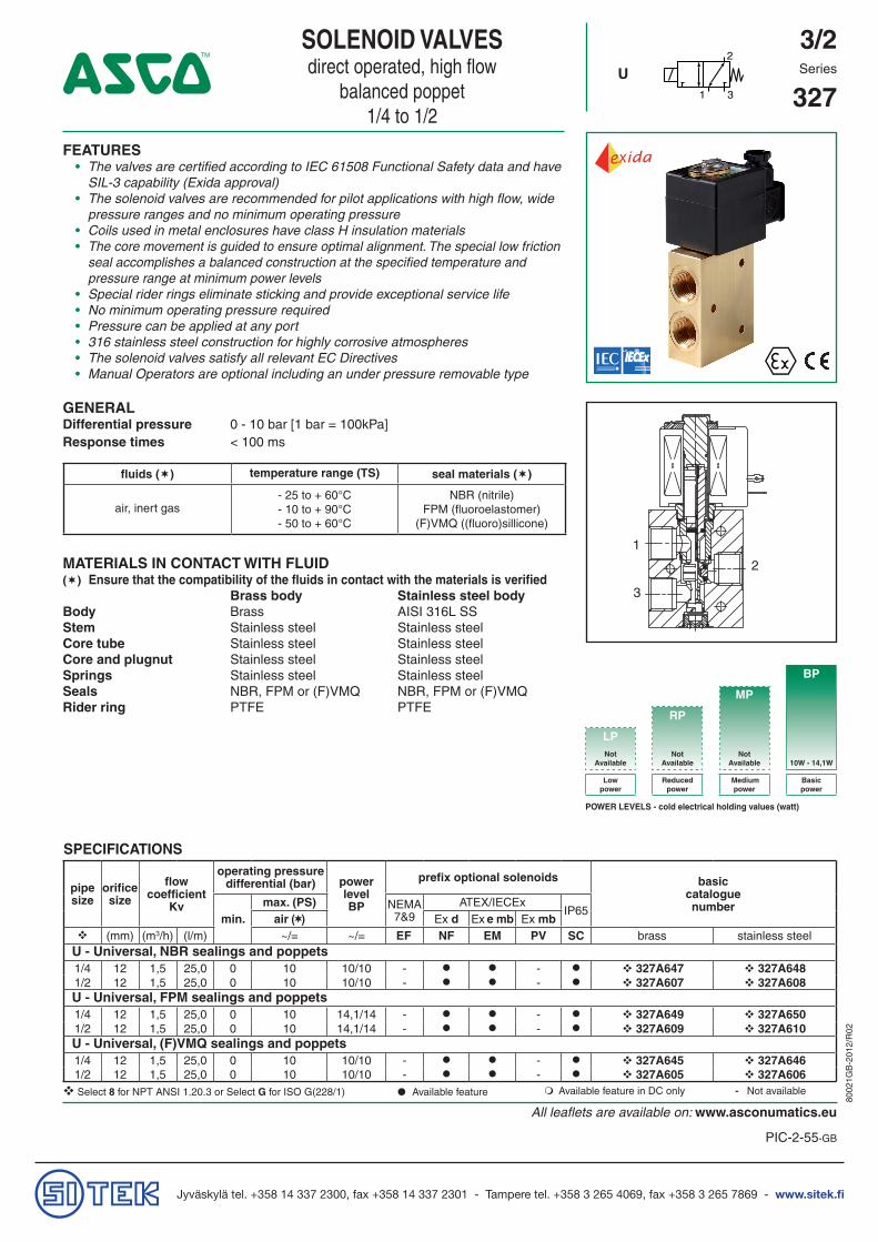
SOLENOID VALVESdirect operated, high flow
balanced poppet1/4 to 1/2
3/22
1 3
U Series
327
FEATURES• The valves are certified according to IEC 61508 Functional Safety data and have
SIL-3 capability (Exida approval)• The solenoid valves are recommended for pilot applications with high flow, wide
pressure ranges and no minimum operating pressure• Coils used in metal enclosures have class H insulation materials• The core movement is guided to ensure optimal alignment. The special low friction
seal accomplishes a balanced construction at the specified temperature andpressure range at minimum power levels
• Special rider rings eliminate sticking and provide exceptional service life• No minimum operating pressure required• Pressure can be applied at any port• 316 stainless steel construction for highly corrosive atmospheres• The solenoid valves satisfy all relevant EC Directives• Manual Operators are optional including an under pressure removable type
GENERALDifferential pressure 0 - 10 bar [1 bar = 100kPa]Response times < 100 ms
fluids () temperature range (TS) seal materials ()
air, inert gas- 25 to + 60°C- 10 to + 90°C- 50 to + 60°C
NBR (nitrile)FPM (fluoroelastomer)
(F)VMQ ((fluoro)sillicone)
MATERIALS IN CONTACT WITH FLUID() Ensure that the compatibility of the fluids in contact with the materials is verified
Brass body Stainless steel bodyBody Brass AISI 316L SSStem Stainless steel Stainless steelCore tube Stainless steel Stainless steelCore and plugnut Stainless steel Stainless steelSprings Stainless steel Stainless steelSeals NBR, FPM or (F)VMQ NBR, FPM or (F)VMQRider ring PTFE PTFE
1
3
2
BP
MP
RP
LPNot
AvailableNot
AvailableNot
Available 10W - 14,1W
Lowpower
Reducedpower
Medium power
Basicpower
POWER LEVELS - cold electrical holding values (watt)
SPECIFICATIONS
pipe size
orificesize
flowcoefficient
Kv
operating pressuredifferential (bar) power
levelBP
prefix optional solenoids basiccataloguenumber
min.max. (PS) NEMA
7&9ATEX/IECEx
IP65air () Ex d Ex e mb Ex mb
(mm) (m3/h) (l/m) ~/= ~/= EF NF EM PV SC brass stainless steelU - Universal, NBR sealings and poppets1/4 12 1,5 25,0 0 10 10/10 - - 327A647 327A6481/2 12 1,5 25,0 0 10 10/10 - - 327A607 327A608U - Universal, FPM sealings and poppets1/4 12 1,5 25,0 0 10 14,1/14 - - 327A649 327A6501/2 12 1,5 25,0 0 10 14,1/14 - - 327A609 327A610U - Universal, (F)VMQ sealings and poppets1/4 12 1,5 25,0 0 10 10/10 - - 327A645 327A6461/2 12 1,5 25,0 0 10 10/10 - - 327A605 327A606Select 8 for NPT ANSI 1.20.3 or Select G for ISO G(228/1) ● Available feature Available feature in DC only - Not available

All leaflets are available on: www.asconumatics.eu
2-55-2
SERIES 327
8002
1GB
-201
2/R
02
PRODUCT SELECTION GUIDESTEP 1Select the fluid temperature range and seal material from the general table on page 1. Select, based on the se-lected seal material (if applicable), the basic catalogue number. Also select the pipe thread identification letter. Example: G327A607
STEP 2Select prefix (combination): Select the appropiate operator from the prefix table on the left. Select for this operator in the electrical characteris-tics table on page 3: the power level (LP,RP,MP,BP) the type of electrical enclosure protection and the desired temperature class. Warning: the ambient temperature range of your application may not exceed the temperature range of your operator (see also on page 3 the section: Explanation of tempera-ture ranges of solenoid valves).Example: SC G327A607
STEP 3Select suffix (combination) if required. Refer to the suffix table on the left. Example: VMS
STEP 4Select voltage. Refer to standard voltages on page 3.Example: 230V / 50Hz
STEP 5Final catalogue / ordering number. Example:SC G327A607 VMS 230V / 50 Hz
PREFIX TABLEprefix description power level
1 2 3 4 5 6 7 LP RP MP BP
E F Explosionproof - NEMA 7, 9 - Zinc plated steel conduit - - - -E V Explosionproof - NEMA 7, 9 - 316 SS conduit - - - -E M Waterproof IP67 - Metal enclosure (EN/IEC 60079-7+18, 61241-1)* - - -
E T Threaded conduit/hole (M20 x 1,5) - - - I S S C Intrinsically safe with SC coil (EN/IEC 60079-11+26, 61241-11)* - - - -N F Flameproof - Aluminium (EN/IEC 60079-1, 60079-31)* - - - P V Encapsulated epoxy moulded (EN/IEC 60079-18, 61241-18)* - - - -S C Solenoid with spade plug connector (EN/IEC 60730) - - - W P Waterproof IP67 - Metal enclosure - - - W P I S I.S. with Metal IP67 enclosure (EN/IEC 60079-11+26, 61241-11)* - - - -W S Waterproof IP67 - 316 SS enclosure - - - W S E M Waterproof IP67 - 316 SS enclosure (EN/IEC 60079-7+18, 61241-1)* - - - W S I S I.S. with 316 SS IP67 enclosure (EN/IEC 60079-11+26, 61241-11)* - - - -W S N F Flameproof - 316 SS (EN/IEC 60079-1, 60079-31)* - - -
T Threaded conduit (1/2" NPT) - - - H C Class H - Battery charging circuit - - - -H T Class H - High temperature - - - -
X Other special constructions - - -
* ATEX solenoid valves are also approved according to EN 13463-1 (non electrical valves)
SUFFIX TABLEsuffix description power level
1 2 3 4 5 LP RP MP BP
E EPDM (ethylene-propylene) - - - -J CR (chloroprene) - - - -N Oxygen service (CR (chloroprene)) - - - -N V FPM (fluoroelastomer) and parts cleaned for oxygen service - - - -V FPM (fluoroelastomer) - - -
C O Epoxy coating on all external surfaces - - - M B Mounting bracket - - - -
P Dry gas, non-lubricated air construction - - - -Q Long life, quiet operation construction - - - -
M O Push type manual operator (2) - - - M S Screw type manual operator (1) (2) - - -
M Metering device - - - -● Available feature Available feature in DC only -Not available(1) Functional Safety certification is not applicable with this feature(2) Under pressure removable execution (see page 5)
OPTIONS & ACCESSORIEScatalogue number
spare part kit no.(2) mountingbracket~ / =
SC 327A605 C117638 SC 327A606 C117638 SC 327A607 C117640 SC 327A608 C117640 SC 327A609 C117640V SC 327A610 C117640V SC 327A645 C117638 SC 327A646 C117638 SC 327A647 C117640 SC 327A648 C117640 SC 327A649 C117640V SC 327A650 C117640V
Select 8 for NPT ANSI 1.20.3 or select G for ISO G(228/1)(2) Standard prefixes/suffixes are also applicable to kits Mounting holes in body
ORDERING EXAMPLES VALVES:SC 8 327A607 24V / DC
WSEMT G 327A608 MS 24V / DCNFET G 327A607 230V / 50 Hz
WSEM G 327A608 MS 24V / DCNF 8 327A645 24V / DCWS G 327A648 MS 24V / DCEM 8 327A607 230V / 50 Hz
WSNF G 327A608 MS 24V / DC
prefixpipe thread voltage
basic number suffix
ORDERING EXAMPLES KITS:C117640 (1)
WSEM C117640 MSNF C117640
WSEM C117640 MS
prefix suffixbasic number
(1) Basic kit number applies to SC coil construction

All leaflets are available on: www.asconumatics.eu
2-55-3
SERIES 327
8002
1GB
-201
2/R
02
EXPLANATION OF TEMPERATURE RANGES OF SOLENOID VALVESValve temperature range The valve temperature range (TS) is determined by the selected seal material, the temperature
range for proper operation of the valve and sometimes by the fluid (e.g. steam)Operator ambient temperature range The operator ambient temperature range is determined by the selected power level and the
safety codeTotal temperature range The temperature range of the complete solenoid valve is determined by the limitations of both
temperature ranges above
ELECTRICAL CHARACTERISTICSCoil insulation class HElectrical safety IEC 335Standard voltages DC (=) 24V - 48V; Allowable voltage variation ± 10% AC (~) 24V - 48V - 115V - 230V/50/60Hz; Other voltages are available on request
prefixoption
power ratings operatorambient
temperaturerange
safety code
electricalenclosureprotection(EN 60529)
replacement coil / kit
type(2)
inrush holding hot/cold~ ~ = ~ =
(VA) (VA) (W) (W) (C°)(1) 230V/50/60 Hz 24V/DC
Basic power (BP)SC 10,0 10,0 10,0 9/10 -40 to +60 EN 60730 IP65, moulded 400924-197 400923-342 01SC 14,1 14,1 14,1 11/14 -40 to +90 EN 60730 IP65, moulded 400924-697 400923-642 01WP/WS 10,0 10,0 10,0 9/10 -40 to +60 EN 60730 IP67, steel /SS 400921-197 400911-342 02WP/WS 14,1 14,1 14,1 11/14 -40 to +90 EN 60730 IP67, steel /SS 400921-697 400911-642 02NF/WSNF 10,0 10,0 10,0 9/10 -60 to +40/60 II2G Ex d IIC Gb T6/T5, II2D Ex t IIIC Db IP67, alu./SS 400921-197 400911-342 03NF/WSNF 14,1 14,1 14,1 11/14 -60 to +40/60/90 II2G Ex d IIC Gb T6/T5, II2D Ex t IIIC Db IP67, alu./SS 400921-697 400911-642 03EM/WSEM 10,0 10,0 10,0 9/10 -40 to +40/60 II2G Ex e mb IIC Gb T4/T3, II2D Ex tb IIIC Db IP67, steel /SS 400921-197 400911-342 02EM/WSEM 14,1 14,1 14,1 11/14 -40 to +40 II2G Ex e mb IIC Gb T3, II2D Ex tb IIIC Db IP67, steel /SS 400921-697 400911-642 02(1) Temperature range can be limited by sealings (2) Refer to the dimensional drawings on page 4 and 5 (3) Multiple coil kits are available under ATEX/IECEx, contact us
- Not available
ELECTRICAL CONNECTIONSprefix connection
SCSpade plug connector with cable gland EN175301-803A (ISO 4400) for cables with an outer diameter from 6 to 10 mm
WP, WS, EM, WSEMM20 cable gland for cables with an outer diameter from 7 to 12 mm. With an internal and external facility for an earthing or bonding conductor
NF, WSNF 1/2" NPT threaded cable entry. Enclosures are supplied without cable gland
NFET, WSNFET M20 x 1,5 threaded cable entry. Enclosures are supplied without cable gland
ADDITIONAL OPTIONS • ManualoperatorMO(pushtype)andMS(screwtype) • 3/8”pipethreadexecution • 1/2”NPT(prefix“T”)andM20x1,5(prefix“ET”)conduits(aluminiumor316SS)availableforsteelsolenoidhousing • Solidstatecomponentsforpeakvoltagesuppressionand/orrectification • FormanualresettypeseepagePIC-11-25 • ManualOperatorsareavailableasshownonpage5
INSTALLATION • Multilanguageinstallation/maintenanceinstructionsareincludedwitheachvalve • Thesolenoidvalvescanbemountedinanypositionwithoutaffectingoperation • Themountingholesareprovidedinthevalvebody • Threadedpipeconnectionidentifieris8=NPT(ANSI1.20.3);G=G(ISO228/1) • Declarationsofconformityareavailableonrequest

All leaflets are available on: www.asconumatics.eu
2-55-4
SERIES 327
8002
1GB
-201
2/R
02
DIMENSIONS (mm), WEIGHT (kg)
TYPE 01: TYPE 02:Epoxy mouldedSC: IEC 335 / ISO 4400
Metal, epoxy coated / AISI 316 SSWP / WS: IEC 335EM / WSEM: EN 60079-7/18 and EN 61241-1
327A605 / A606 / A607 / A608 / A609 / A610327A645 / A646 / A647 / A648 / A649 / A650
327A605 / A606 / A607 / A608 / A609 / A610327A645 / A646 / A647 / A648 / A649 / A650
Manual operator(MO/MS) execution
360°
Manual operator(MO/MS) execution
360°
TYPE 03:Aluminium, epoxy coated / AISI 316 SSNF / WSNF: EN/IEC 60079-1 and EN/IEC 60079-31
327A605 / A606 / A607 / A608 / A609 / A610327A645 / A646 / A647 / A648 / A649 / A650
Manual operator(MO/MS) execution
360°
type prefix/option power level
A B C D E F G H J K L M N weight
01 SC BP 50 30 135 95 54 32 100 23 70 60 38 40 54 1,6 kg
02 WP, WS, EM/WSEM BP 75 30 140 95 54 120 80 60 38 40 54 - - 1,6 kg
03NF BP 97 30 165 115 54 32 102 55 60 100 38 40 54 2,4 kg
WSNF BP 97 30 165 115 54 32 102 55 60 100 38 40 54 3,8 kg

All leaflets are available on: www.asconumatics.eu
2-55-5
SERIES 327
8002
1GB
-201
2/R
02
SECTIONAL DRAWINGS
Manual Operator (MS) Manual Operator (MO) Removable Manual Operator (MS) / (MO)
adapter
plug
29 m
m
Suffix MS Suffix MO Mounted adapter use TPL 26710
Removable Manual Operator Kit number
MS typeMO typeAdapter type
C325324C325323C325410
2
1
3
2
1
3
2
1
3
REMOVABLE MO / MS TOOL
Tool to remove plug. Kit no.: C325325

All leaflets are available on: www.asconumatics.eu
2-55-6
PIC
-02-
0055
-GB
--
Ava
ilabi
lity,
des
ign
and
spec
ifica
tions
are
sub
ject
to c
hang
e w
ithou
t not
ice.
All
right
s re
serv
ed.
8002
1GB
-201
2/R
02