solid carbide thread mills
TRANSCRIPT

ET/EDTSolid Carbide Thread Mills for High-Hardness Steels
FEATURES
Capable of thread milling of high-hardness steels of 45HRC or higher
Tip shape reduces cutting resistance and suppresses tool bending
Epoch D Thread Mill can perform drilling and threading simultaneously
Advanced tool coatings provide improved cutting performance and extended tool life

© 2016 Mitsubishi Hitachi Tool Engineering, Ltd.2
FeaturesET/EDT
2. Features of Epoch D Thread Mill
• No pilot hole needed. This single tool can perform both drilling and threading simultaneously.
• High-strength edge shape design suppresses edge tip breakage in severe machining environments including hardened steels.
• ATH Coating delivers improved hardness and oxidation resistance.
INTRODUCTION
The new EDT Series Thread Mill Series is designed to machine precision threads in a range of materials including hardened steels up to 66HRC. Our thread mills deliver improved cutting and chip removal, reducing the risk of the cutting tool breaking off inside of the hole.
Additionally, one thread mill can perform a variety of applications including right-hand thread milling, left-hand thread milling, and fine threading simply by changing the NC program. Cutting load is much smaller than conventional taps, and special toolholders are not needed.
1. Features of Epoch Thread Mill
• Tough and strong edge design for threading in hardened steels. • Tip shape reduces cutting resistance and suppresses tool bending. • Drastically reduces tool breakage • PN Coating provides excellent adhesion and wear resistance
FEATURES
3. New PVD Coating Technology
Advanced TH (ATH) Coating: With a hardness of 3800Hv and oxidation temperature of 1200°, our new ATH Coating enables longer life and higher efficiency when cutting high-hardness materials (55HRC or higher). Compared with our previous generation coating, double the tool life and more than double the machining efficiency can be achieved. The ATH Coating is ideal for both dry cutting and wet cutting in a variety of materials including cold-worked die steel, HSS, tool steel, composite materials, carbide alloys and more.
Cross-section photograph of ATH coating layer structure
■ Conventional Coating ■ ATH Coating for hard materialPat.No.3934136
5nm
High hardnessmembrane
High heat resistance membrane
Even finer particle size is nano order.

3© 2016 Mitsubishi Hitachi Tool Engineering, Ltd.
FeaturesET/EDT
5. Machining Process with Epoch Thread Mill
4. Technology
Reduces the risk of tool breaking By using a tool with a diameter smaller than the inside diameter of the thread, cutting chips are smaller and chip evacuation is improved. The risk of the tool breaking off inside the hole is reduced as a result.
One tool – various types of thread milling Right-hand, left-hand and fine thread milling can be performed by just changing the NC program. The nominal diameters of the coarse threads and fine threads that can be processed with the same tool are different. (Example: For ET-1.25-16-PN, coarse thread is M8 × P1.25 and fine thread is M10 × P1.25).
Cutting conditions can be freely set Unlike when using taps, synchronizing the rotation and feed rates is not necessary. Thread mills can be used in the same manner as end mills and cutting conditions can be set according to the processing environment.
Usable on a variety of machines Thread mills can be used even on machines with lower-powered spindles. In addition, special tooling such as tapping holders are not necessary.
Provides good finished surfaces Interrupted cutting suppresses gouging to provide good finished surfaces.
Thread milling can be performed to the bottom of the hole Epoch Thread Mills are designed with no incomplete crests and Epoch D Thread Mills have only one incomplete crest, making them ideal for when you want to perform thread milling to the bottom of shallow holes.
1. Startup2. Position for starting point
of machining3. Entry (gradually cutting in)
4. Threading5. Release (gradually
detaching from cutting)6. Ending
Easily Create NC Programs Online Create cutting programs for the ET and EDT mills in our app at: http://www.mmc-hitachitool.co.jp/e/index.html
1 2 3 4 5 6
PN Coating: By optimizing the AI content, the multi-layer PN Coating exhibits both excellent heat-resistance and adhesion to the tool substrate. Combining of the AlCr coating layer with Si produces high hardness (3000HV) as well as good wear resistance. PN Coating provides extended cutting tool life in both wet and dry machining of materials including pre-hardened steel, carbon steel, alloy steel, stainless steel, H13, D2 and more.
Epoch D Thread Mill can perform boring simultaneously.
Left-hand cutting tool – Reverse spindle rotation should be used.

© 2016 Mitsubishi Hitachi Tool Engineering, Ltd.4
Tool DimensionsInchET
THREADING
65HRC 65 4 FLUTES PN COATING
øDc øDs
Ll
ET - 2D for Unified Threads
Part No. Stock Thread Diameter tpi Dc Flutes L Ds
Limit Correction
Amount
ET-U64-3.7-PN □ 0.073 No.1-64UNC 64 0.055 4 0.146 1.97 6mm 0.00157
ET-U56-4.4-PN □ 0.086 No.2-56UNC 56 0.065 4 0.173 1.97 6mm 0.00197
ET-U48-5-PN □ 0.099 No.3-48UNC 48 0.075 4 0.197 1.97 6mm 0.00236
ET-U40-5.7-PN □ 0.112 No.4-40UNC 40 0.083 4 0.224 1.97 6mm 0.00276
ET-U32-7-PN □ 0.138 No.6-32UNC 32 0.100 4 0.276 1.97 6mm 0.00315
ET-U36-8.3-PN □ 0.164 No.8-36UNF 36 0.130 4 0.327 1.97 6mm 0.00354
ET-U24-9.7-PN □ 0.190 No.10-24UNC 24 0.138 4 0.382 2.76 6mm 0.00433
ET-U20-12.7-PN ● 1/4" No.1/4-20UNC 20 0.187 4 0.500 2.76 6mm 0.00591
ET-U28-12.7-PN ● 1/4" No.1/4-28UNF 28 0.197 4 0.500 2.76 6mm 0.00591
ET-U18-15.9-PN ● 5/16" No.5/16-18UNC 18 0.236 4 0.626 3.15 10mm 0.00709
ET-U16-19.1-PN ● 3/8" No.3/8-16UNC 16 0.264 4 0.752 3.15 10mm 0.00866
ET-U14-22.2-PN □ 7/16" No.7/16-14UNC 14 0.303 4 0.874 3.15 10mm 0.00984
ET-U13-25.4-PN ● 1/2" No.1/2-13UNC 13 0.362 4 1.000 3.15 10mm 0.01142
ET-U12-28.6-PN □ 9/16" No.9/16-12UNC 12 0.413 4 1.126 3.94 12mm 0.01260
ET-U11-31.8-PN ● 5/8" No.5/8-11UNC 11 0.449 4 1.252 3.94 12mm 0.01378
ET - 2.5D for Unified Threads
Part No. Stock Thread Diameter tpi Dc Flutes L Ds
Limit Correction
Amount
ET-U64-4.6-PN □ 0.073 No.1-64UNC 64 0.055 4 0.181 1.97 6mm 0.00157
ET-U56-5.5-PN □ 0.086 No.2-56UNC 56 0.065 4 0.217 1.97 6mm 0.00197
ET-U48-6.3-PN □ 0.099 No.3-48UNC 48 0.075 4 0.248 1.97 6mm 0.00236
ET-U40-7.1-PN □ 0.112 No.4-40UNC 40 0.083 4 0.280 1.97 6mm 0.00276
ET-U32-8.8-PN □ 0.138 No.6-32UNC 32 0.100 4 0.346 1.97 6mm 0.00315
ET-U36-10.4-PN □ 0.164 No.8-36UNF 36 0.130 4 0.409 1.97 6mm 0.00354
ET-U24-12.1-PN □ 0.190 No.10-24UNC 24 0.138 4 0.476 2.76 6mm 0.00433
ET-U20-15.9-PN ● 1/4" No.1/4-20UNC 20 0.187 4 0.626 2.76 6mm 0.00591
ET-U28-15.9-PN ● 1/4" No.1/4-28UNF 28 0.197 4 0.626 2.76 6mm 0.00591
ET-U18-19.8-PN ● 5/16" No.5/16-18UNC 18 0.236 4 0.780 3.15 10mm 0.00709
ET-U16-23.8-PN ● 3/8" No.3/8-16UNC 16 0.264 4 0.937 3.15 10mm 0.00866
ET-U14-27.8-PN □ 7/16" No.7/16-14UNC 14 0.303 4 1.094 3.15 10mm 0.00984
ET-U13-31.8-PN ● 1/2" No.1/2-13UNC 13 0.362 4 1.252 3.15 10mm 0.01142
ET-U12-35.7-PN □ 9/16" No.9/16-12UNC 12 0.413 4 1.406 3.94 12mm 0.01260
ET-U11-39.7-PN ● 5/8" No.5/8-11UNC 11 0.449 4 1.563 3.94 12mm 0.01378
Pilot hole required
= Stocked in Japan Distributor. Please contact our customer service.

5© 2016 Mitsubishi Hitachi Tool Engineering, Ltd.
Tool DimensionsMetricET
THREADING
65HRC 65 4 FLUTES PN COATING
øDc øDs
Ll
ET - 2D for Metric Threads
Part No. Stock Size P Dc Flutes L Ds
Limit Correction
Amount
ET-0.4-4-PN □ M2 0.4 1.4 4 4 50 6 0.04
ET-0.45-4.4-PN □ M2.2 0.45 1.6 4 4.4 50 6 0.04
ET-0.45-5-PN □ M2.5 0.45 1.8 4 5 50 6 0.05
ET-0.5-6-PN ● M3 0.5 2.4 4 6 50 6 0.06
ET-0.7-8-PN ● M4 0.7 3.1 4 8 50 6 0.08
ET-0.8-10-PN ● M5 0.8 3.8 4 10 50 6 0.1
ET-1.0-12-PN ● M6 1 4.6 4 12 50 6 0.11
ET-1.25-16-PN ● M8 1.25 6.2 4 16 70 10 0.15
ET-1.5-20-PN ● M10 1.5 7.5 4 20 70 10 0.18
ET-1.75-24-PN ● M12 1.75 9 4 24 80 10 0.22
ET-2-32-PN □ M16 2 11.5 4 32 100 12 0.29
ET-2.5-36-PN □ M18 2.5 14 4 36 135 16 0.32
ET-2.5-40-PN □ M20 2.5 15 4 40 135 16 0.36
ET - 2.5D for Metric Threads
Part No. Stock Size P Dc Flutes L Ds
Limit Correction
Amount
ET-0.4-5-PN □ M2 0.4 1.4 4 5 50 6 0.04
ET-0.45-5.5-PN □ M2.2 0.45 1.6 4 5.5 50 6 0.04
ET-0.45-6.25-PN □ M2.5 0.45 1.8 4 6.25 50 6 0.05
ET-0.5-7.5-PN ● M3 0.5 2.4 4 7.5 50 6 0.06
ET-0.7-10-PN ● M4 0.7 3.1 4 10 50 6 0.08
ET-0.8-12.5-PN ● M5 0.8 3.8 4 12.5 50 6 0.1
ET-1.0-15-PN ● M6 1 4.6 4 15 50 6 0.11
ET-1.25-20-PN ● M8 1.25 6.2 4 20 70 10 0.15
ET-1.5-25-PN ● M10 1.5 7.5 4 25 70 10 0.18
ET-1.75-30-PN ● M12 1.75 9 4 30 80 10 0.22
ET-2-40-PN □ M16 2 11.5 4 40 100 12 0.29
ET-2.5-45-PN □ M18 2.5 14 4 45 135 16 0.32
ET-2.5-50-PN □ M20 2.5 15 4 50 135 16 0.36
Pilot hole required
= Stocked in Japan Distributor. Please contact our customer service.

© 2016 Mitsubishi Hitachi Tool Engineering, Ltd.6
Tool DimensionsInchEDT
øDc øDs
Ll
THREADING
65HRC 65 4 FLUTES ATH COATING
EDT - 2D for Unified Threads
Part No. Stock Thread Diameter tpi Dc Flutes L Ds Oil Hole
Limit Correction
Amount
EDT-U64-3.7-TH □ 0.073 No.1-64UNC 64 0.0551 4 0.146 1.97 6mm - 0.00157
EDT-U56-4.4-TH □ 0.086 No.2-56UNC 56 0.0650 4 0.173 1.97 6mm - 0.00197
EDT-U48-5-TH □ 0.099 No.3-48UNC 48 0.0748 4 0.197 1.97 6mm - 0.00236
EDT-U40-5.7-TH □ 0.112 No.4-40UNC 40 0.0827 4 0.224 1.97 6mm - 0.00276
EDT-U32-7-TH □ 0.138 No.6-32UNC 32 0.1004 4 0.276 1.97 6mm - 0.00315
EDT-U36-8.3-TH □ 0.164 No.8-36UNF 36 0.1299 4 0.327 1.97 6mm - 0.00354
EDT-U24-9.7-TH □ 0.190 No.10-24UNC 24 0.1378 4 0.382 2.76 6mm - 0.00433
EDT-U20-12.7-TH ● 1/4” No.1/4-20UNC 20 0.1870 4 0.500 2.76 6mm - 0.00591
EDT-U28-12.7-TH ● 1/4” No.1/4-28UNF 28 0.1969 4 0.500 2.76 6mm - 0.00591
EDT-U18-15.9-TH ● 5/16” No.5/16-18UNC 18 0.2362 4 0.626 3.15 10mm - 0.00709
EDT-U16-19.1-TH ● 3/8” No.3/8-16UNC 16 0.2638 4 0.752 3.15 10mm - 0.00866
EDT-U14-22.2-TH □ 7/16” No.7/16-14UNC 14 0.3031 4 0.874 3.15 10mm ○ 0.00984
EDT-U13-25.4-TH ● 1/2” No.1/2-13UNC 13 0.3622 4 1.000 3.15 10mm ○ 0.01142
EDT-U12-28.6-TH □ 9/16” No.9/16-12UNC 12 0.4134 4 1.126 3.94 12mm ○ 0.01260
EDT-U11-31.8-TH ● 5/8” No.5/8-11UNC 11 0.4488 4 1.252 3.94 12mm ○ 0.01378
EDT - 2.5D for Unified Threads
Part No. Stock Thread Diameter tpi Dc Flutes L Ds Oil Hole
Limit Correction
Amount
EDT-U64-4.6-TH □ 0.073 No.1-64UNC 64 0.0551 4 0.181 1.97 6mm - 0.00157
EDT-U56-5.5-TH □ 0.086 No.2-56UNC 56 0.0650 4 0.217 1.97 6mm - 0.00197
EDT-U48-6.3-TH □ 0.099 No.3-48UNC 48 0.0748 4 0.248 1.97 6mm - 0.00236
EDT-U40-7.1-TH □ 0.112 No.4-40UNC 40 0.0827 4 0.280 1.97 6mm - 0.00276
EDT-U32-8.8-TH □ 0.138 No.6-32UNC 32 0.1004 4 0.346 1.97 6mm - 0.00315
EDT-U36-10.4-TH □ 0.164 No.8-36UNF 36 0.1299 4 0.409 1.97 6mm - 0.00354
EDT-U24-12.1-TH □ 0.190 No.10-24UNC 24 0.1378 4 0.476 2.76 6mm - 0.00433
EDT-U20-15.9-TH ● 1/4” No.1/4-20UNC 20 0.1870 4 0.626 2.76 6mm - 0.00591
EDT-U28-15.9-TH ● 1/4” No.1/4-28UNF 28 0.1969 4 0.626 2.76 6mm - 0.00591
EDT-U18-19.8-TH ● 5/16” No.5/16-18UNC 18 0.2362 4 0.780 3.15 10mm - 0.00709
EDT-U16-23.8-TH ● 3/8” No.3/8-16UNC 16 0.2638 4 0.937 3.15 10mm - 0.00866
EDT-U14-27.8-TH □ 7/16” No.7/16-14UNC 14 0.3031 4 1.094 3.15 10mm ○ 0.00984
EDT-U13-31.8-TH ● 1/2” No.1/2-13UNC 13 0.3622 4 1.252 3.15 10mm ○ 0.01142
EDT-U12-35.7-TH □ 9/16” No.9/16-12UNC 12 0.4134 4 1.406 3.94 12mm ○ 0.01260
EDT-U11-39.7-TH ● 5/8” No.5/8-11UNC 11 0.4488 4 1.563 3.94 12mm ○ 0.01378
Pilot hole not required
= Stocked in Japan Distributor. Please contact our customer service.

7© 2016 Mitsubishi Hitachi Tool Engineering, Ltd.
Tool DimensionsMetricEDT
THREADING
65HRC 65 4 FLUTES ATH COATING
øDc øDs
Ll
EDT - 2D for Metric Threads
Part No. Stock Size P Dc Flutes L Ds Oil Hole
Limit Correction
Amount
EDT-0.4-4-TH □ M2 0.4 1.4 4 4 50 6 - 0.04
EDT-0.45-4.4-TH □ M2.2 0.45 1.6 4 4.4 50 6 - 0.04
EDT-0.45-5-TH □ M2.5 0.45 1.8 4 5 50 6 - 0.05
EDT-0.5-6-TH ● M3 0.5 2.4 4 6 50 6 - 0.06
EDT-0.7-8-TH ● M4 0.7 3.1 4 8 50 6 - 0.08
EDT-0.8-10-TH ● M5 0.8 3.8 4 10 50 6 - 0.1
EDT-1.0-12-TH ● M6 1 4.6 4 12 50 6 - 0.11
EDT-1.25-16-TH ● M8 1.25 6.2 4 16 70 10 - 0.15
EDT-1.5-20-TH ● M10 1.5 7.5 4 20 70 10 ○ 0.18
EDT-1.75-24-TH ● M12 1.75 9 4 24 80 10 ○ 0.22
EDT-2-32-TH □ M16 2 11.5 4 32 100 12 ○ 0.29
EDT-2.5-36-TH □ M18 2.5 14 4 36 135 16 ○ 0.32
EDT-2.5-40-TH □ M20 2.5 15 4 40 135 16 ○ 0.36
EDT - 2.5D for Metric Threads
Part No. Stock Size P Dc Flutes L Ds Oil Hole
Limit Correction
Amount
EDT-0.4-5-TH □ M2 0.4 1.4 4 5 50 6 - 0.04
EDT-0.45-5.5-TH □ M2.2 0.45 1.6 4 5.5 50 6 - 0.04
EDT-0.45-6.25-TH □ M2.5 0.45 1.8 4 6.25 50 6 - 0.05
EDT-0.5-7.5-TH ● M3 0.5 2.4 4 7.5 50 6 - 0.06
EDT-0.7-10-TH ● M4 0.7 3.1 4 10 50 6 - 0.08
EDT-0.8-12.5-TH ● M5 0.8 3.8 4 12.5 50 6 - 0.1
EDT-1.0-15-TH ● M6 1 4.6 4 15 50 6 - 0.11
EDT-1.25-20-TH ● M8 1.25 6.2 4 20 70 10 - 0.15
EDT-1.5-25-TH ● M10 1.5 7.5 4 25 70 10 ○ 0.18
EDT-1.75-30-TH ● M12 1.75 9 4 30 80 10 ○ 0.22
EDT-2-40-TH □ M16 2 11.5 4 40 100 12 ○ 0.29
EDT-2.5-45-TH □ M18 2.5 14 4 45 135 16 ○ 0.32
EDT-2.5-50-TH □ M20 2.5 15 4 50 135 16 ○ 0.36
Pilot hole not required
= Stocked in Japan Distributor. Please contact our customer service.
© 2016 Mitsubishi Hitachi Tool Engineering, Ltd.8
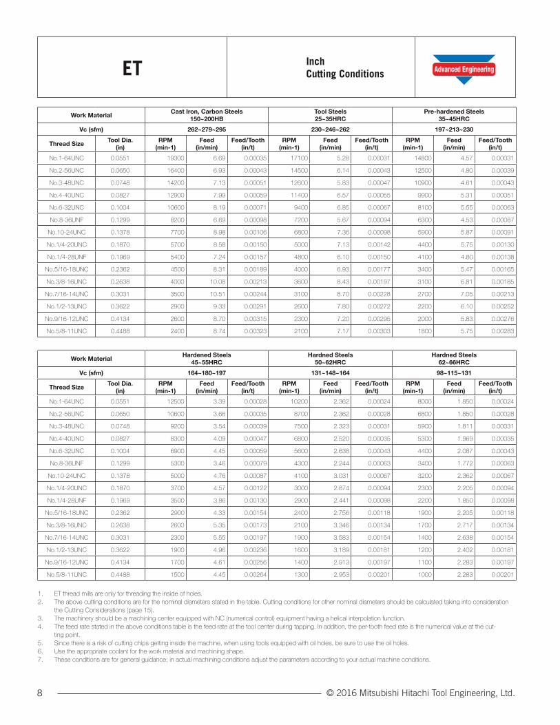
ET InchCutting Conditions
Work MaterialCast Iron, Carbon Steels
150~200HBTool Steels25~35HRC
Pre-hardened Steels 35~45HRC
Vc (sfm) 262~279~295 230~246~262 197~213~230
Thread SizeTool Dia.
(in)RPM
(min-1)Feed
(in/min)Feed/Tooth
(in/t)RPM
(min-1)Feed
(in/min)Feed/Tooth
(in/t)RPM
(min-1)Feed
(in/min)Feed/Tooth
(in/t)
No.1-64UNC 0.0551 19300 6.69 0.00035 17100 5.28 0.00031 14800 4.57 0.00031
No.2-56UNC 0.0650 16400 6.93 0.00043 14500 6.14 0.00043 12500 4.80 0.00039
No.3-48UNC 0.0748 14200 7.13 0.00051 12600 5.83 0.00047 10900 4.61 0.00043
No.4-40UNC 0.0827 12900 7.99 0.00059 11400 6.57 0.00055 9900 5.31 0.00051
No.6-32UNC 0.1004 10600 8.19 0.00071 9400 6.85 0.00067 8100 5.55 0.00063
No.8-36UNF 0.1299 8200 6.69 0.00098 7200 5.67 0.00094 6300 4.53 0.00087
No.10-24UNC 0.1378 7700 8.98 0.00106 6800 7.36 0.00098 5900 5.87 0.00091
No.1/4-20UNC 0.1870 5700 8.58 0.00150 5000 7.13 0.00142 4400 5.75 0.00130
No.1/4-28UNF 0.1969 5400 7.24 0.00157 4800 6.10 0.00150 4100 4.80 0.00138
No.5/16-18UNC 0.2362 4500 8.31 0.00189 4000 6.93 0.00177 3400 5.47 0.00165
No.3/8-16UNC 0.2638 4000 10.08 0.00213 3600 8.43 0.00197 3100 6.81 0.00185
No.7/16-14UNC 0.3031 3500 10.51 0.00244 3100 8.70 0.00228 2700 7.05 0.00213
No.1/2-13UNC 0.3622 2900 9.33 0.00291 2600 7.80 0.00272 2200 6.10 0.00252
No.9/16-12UNC 0.4134 2600 8.70 0.00315 2300 7.20 0.00295 2000 5.83 0.00276
No.5/8-11UNC 0.4488 2400 8.74 0.00323 2100 7.17 0.00303 1800 5.75 0.00283
Work MaterialHardened Steels
45~55HRCHardned Steels
50~62HRCHardned Steels
62~66HRC
Vc (sfm) 164~180~197 131~148~164 98~115~131
Thread SizeTool Dia.
(in)RPM
(min-1)Feed
(in/min)Feed/Tooth
(in/t)RPM
(min-1)Feed
(in/min)Feed/Tooth
(in/t)RPM
(min-1)Feed
(in/min)Feed/Tooth
(in/t)
No.1-64UNC 0.0551 12500 3.39 0.00028 10200 2.362 0.00024 8000 1.850 0.00024
No.2-56UNC 0.0650 10600 3.66 0.00035 8700 2.362 0.00028 6800 1.850 0.00028
No.3-48UNC 0.0748 9200 3.54 0.00039 7500 2.323 0.00031 5900 1.811 0.00031
No.4-40UNC 0.0827 8300 4.09 0.00047 6800 2.520 0.00035 5300 1.969 0.00035
No.6-32UNC 0.1004 6900 4.45 0.00059 5600 2.638 0.00043 4400 2.087 0.00043
No.8-36UNF 0.1299 5300 3.46 0.00079 4300 2.244 0.00063 3400 1.772 0.00063
No.10-24UNC 0.1378 5000 4.76 0.00087 4100 3.031 0.00067 3200 2.362 0.00067
No.1/4-20UNC 0.1870 3700 4.57 0.00122 3000 2.874 0.00094 2300 2.205 0.00094
No.1/4-28UNF 0.1969 3500 3.86 0.00130 2900 2.441 0.00098 2200 1.850 0.00098
No.5/16-18UNC 0.2362 2900 4.33 0.00154 2400 2.756 0.00118 1900 2.205 0.00118
No.3/8-16UNC 0.2638 2600 5.35 0.00173 2100 3.346 0.00134 1700 2.717 0.00134
No.7/16-14UNC 0.3031 2300 5.55 0.00197 1900 3.583 0.00154 1400 2.638 0.00154
No.1/2-13UNC 0.3622 1900 4.96 0.00236 1600 3.189 0.00181 1200 2.402 0.00181
No.9/16-12UNC 0.4134 1700 4.61 0.00256 1400 2.913 0.00197 1100 2.283 0.00197
No.5/8-11UNC 0.4488 1500 4.45 0.00264 1300 2.953 0.00201 1000 2.283 0.00201
1. ET thread mills are only for threading the inside of holes.2. The above cutting conditions are for the nominal diameters stated in the table. Cutting conditions for other nominal diameters should be calculated taking into consideration
the Cutting Considerations (page 15).3. The machinery should be a machining center equipped with NC (numerical control) equipment having a helical interpolation function.4. The feed rate stated in the above conditions table is the feed rate at the tool center during tapping. In addition, the per-tooth feed rate is the numerical value at the cut-
ting point.5. Since there is a risk of cutting chips getting inside the machine, when using tools equipped with oil holes, be sure to use the oil holes.6. Use the appropriate coolant for the work material and machining shape.7. These conditions are for general guidance; in actual machining conditions adjust the parameters according to your actual machine conditions.

9© 2016 Mitsubishi Hitachi Tool Engineering, Ltd.
Work MaterialCast Iron, Carbon Steels
150~200HBTool Steels25~35HRC
Pre-hardened Steels 35~45HRC
Vc(m/min) 80~85~90 70~75~80 60~65~70
Thread SizeTool Dia.
(mm)RPM
n(min-1)Vf (mm/min) fz (mm/t)
RPM n(min-1)
Vf (mm/min) fz (mm/t)RPM
n(min-1)Vf (mm/min) fz (mm/t)
M2 1.4 19300 208 0.009 17100 164 0.008 14800 142 0.008
M2.2 1.6 16900 203 0.011 14900 163 0.01 12900 141 0.01
M2.5 1.8 15000 202 0.012 13300 164 0.011 11500 142 0.011
M3 2.4 11300 154 0.017 9900 127 0.016 8600 103 0.015
M4 3.1 8700 188 0.024 7700 152 0.022 6700 127 0.021
M5 3.8 7100 198 0.029 6300 163 0.027 5400 130 0.025
M6 4.6 5900 204 0.037 5200 170 0.035 4500 134 0.032
M8 6.2 4400 198 0.05 3900 165 0.047 3300 128 0.043
M10 7.5 3600 216 0.06 3200 179 0.056 2800 148 0.053
M12 9 3000 216 0.072 2700 184 0.068 2300 145 0.063
M16 11.5 2400 235 0.087 2100 194 0.082 1800 154 0.076
M18 14 1900 171 0.101 1700 144 0.095 1500 117 0.088
M20 15 1800 184 0.102 1600 154 0.096 1400 125 0.089
Work MaterialHardened Steels
45~55HRCHardned Steels
55~62HRCHardned Steels
62~66HRC
Vc(m/min) 50~55~60 40~45~50 30~35~40
Thread SizeTool Dia.
(mm)RPM
n(min-1)Vf (mm/min) fz (mm/t)
RPM n(min-1)
Vf (mm/min) fz (mm/t)RPM
n(min-1)Vf (mm/min) fz (mm/t)
M2 1.4 12500 105 0.007 10200 73 0.006 8000 58 0.006
M2.2 1.6 10900 107 0.009 9000 69 0.007 7000 53 0.007
M2.5 1.8 9700 109 0.01 8000 72 0.008 6200 56 0.008
M3 2.4 7300 82 0.014 6000 53 0.011 4600 40 0.011
M4 3.1 5600 96 0.019 4600 62 0.015 3600 49 0.015
M5 3.8 4600 102 0.023 3800 66 0.018 2900 50 0.018
M6 4.6 3800 106 0.03 3100 67 0.023 2400 52 0.023
M8 6.2 2800 101 0.04 2300 64 0.031 1800 50 0.031
M10 7.5 2300 113 0.049 1900 72 0.038 1500 57 0.038
M12 9 1900 112 0.059 1600 72 0.045 1200 54 0.045
M16 11.5 1500 120 0.071 1200 74 0.055 1000 62 0.055
M18 14 1300 95 0.082 1000 56 0.063 800 45 0.063
M20 15 1200 100 0.083 1000 64 0.064 700 45 0.064
ET MetricCutting Conditions
1. ET thread mills are only for threading the inside of holes.2. The above cutting conditions are for the nominal diameters stated in the table. Cutting conditions for other nominal diameters should be calculated taking into consideration
the Cutting Considerations (page 15).3. The machinery should be a machining center equipped with NC (numerical control) equipment having a helical interpolation function.4. The feed rate stated in the above conditions table is the feed rate at the tool center during tapping. In addition, the per-tooth feed rate is the numerical value at the cut-
ting point.5. Since there is a risk of cutting chips getting inside the machine, when using tools equipped with oil holes, be sure to use the oil holes.6. Use the appropriate coolant for the work material and machining shape.7. These conditions are for general guidance; in actual machining conditions adjust the parameters according to your actual machine conditions.

© 2016 Mitsubishi Hitachi Tool Engineering, Ltd.10
EDT InchCutting Conditions
Work MaterialCast Iron, Carbon Steels
150~200HBTool Steels25~35HRC
Pre-hardened Steels 35~45HRC
Vc (sfm) 262~279~295 230~246~262 197~213~230
Thread SizeTool Dia.
(in)RPM
(min-1)Feed
(in/min)Feed/Tooth
(in/t)RPM
(min-1)Feed
(in/min)Feed/Tooth
(in/t)RPM
(min-1)Feed
(in/min)Feed/Tooth
(in/t)
No.1-64UNC 0.0551 19300 4.45 0.00024 17100 3.94 0.00024 14800 3.43 0.00024
No.2-56UNC 0.0650 16400 4.41 0.00028 14500 3.90 0.00028 12500 3.39 0.00028
No.3-48UNC 0.0748 14200 4.37 0.00031 12600 3.90 0.00031 10900 3.35 0.00031
No.4-40UNC 0.0827 12900 4.80 0.00035 11400 4.21 0.00035 9900 3.66 0.00035
No.6-32UNC 0.1004 10600 5.00 0.00043 9400 4.45 0.00043 8100 3.82 0.00043
No.8-36UNF 0.1299 8200 4.29 0.00063 7200 3.78 0.00063 6300 3.31 0.00063
No.10-24UNC 0.1378 7700 5.67 0.00067 6800 5.00 0.00067 5900 4.33 0.00067
No.1/4-20UNC 0.1870 5700 5.43 0.00094 5000 4.76 0.00094 4400 4.17 0.00094
No.1/4-28UNF 0.1969 5400 4.53 0.00098 4800 4.02 0.00098 4100 3.43 0.00098
No.5/16-18UNC 0.2362 4500 5.20 0.00118 4000 4.61 0.00118 3400 3.94 0.00118
No.3/8-16UNC 0.2638 4000 6.34 0.00134 3600 5.71 0.00134 3100 4.92 0.00134
No.7/16-14UNC 0.3031 3500 6.61 0.00154 3100 5.83 0.00154 2700 5.08 0.00154
No.1/2-13UNC 0.3622 2900 5.79 0.00181 2600 5.20 0.00181 2200 4.41 0.00181
No.9/16-12UNC 0.4134 2600 5.43 0.00197 2300 4.80 0.00197 2000 4.17 0.00197
No.5/8-11UNC 0.4488 2400 5.43 0.00201 2100 4.76 0.00201 1800 4.09 0.00201
Work MaterialHardened Steels
45~55HRCHardned Steels
55~62HRCHardned Steels
62~66HRC
Vc (sfm) 164~180~197 131~148~164 98~115~131
Thread SizeTool Dia.
(in)RPM
(min-1)Feed
(in/min)Feed/Tooth
(in/t)RPM
(min-1)Feed
(in/min)Feed/Tooth
(in/t)RPM
(min-1)Feed
(in/min)Feed/Tooth
(in/t)
No.1-64UNC 0.0551 12500 2.87 0.00024 10200 2.36 0.00024 8000 1.85 0.00024
No.2-56UNC 0.0650 10600 2.87 0.00028 8700 2.36 0.00028 6800 1.85 0.00028
No.3-48UNC 0.0748 9200 2.83 0.00031 7500 2.32 0.00031 5900 1.81 0.00031
No.4-40UNC 0.0827 8300 3.07 0.00035 6800 2.52 0.00035 5300 1.97 0.00035
No.6-32UNC 0.1004 6900 3.27 0.00043 5600 2.64 0.00043 4400 2.09 0.00043
No.8-36UNF 0.1299 5300 2.80 0.00063 4300 2.24 0.00063 3400 1.77 0.00063
No.10-24UNC 0.1378 5000 3.66 0.00067 4100 3.03 0.00067 3200 2.36 0.00067
No.1/4-20UNC 0.1870 3700 3.50 0.00094 3000 2.87 0.00094 2300 2.20 0.00094
No.1/4-28UNF 0.1969 3500 2.91 0.00098 2900 2.44 0.00098 2200 1.85 0.00098
No.5/16-18UNC 0.2362 2900 3.35 0.00118 2400 2.76 0.00118 1900 2.20 0.00118
No.3/8-16UNC 0.2638 2600 4.13 0.00134 2100 3.35 0.00134 1700 2.72 0.00134
No.7/16-14UNC 0.3031 2300 4.33 0.00154 1900 3.58 0.00154 1400 2.64 0.00154
No.1/2-13UNC 0.3622 1900 3.78 0.00181 1600 3.19 0.00181 1200 2.40 0.00181
No.9/16-12UNC 0.4134 1700 3.54 0.00197 1400 2.91 0.00197 1100 2.28 0.00197
No.5/8-11UNC 0.4488 1500 3.39 0.00201 1300 2.95 0.00201 1000 2.28 0.00201
1. EDT thread mills are capable of simultaneous boring and threading.2. The above cutting conditions are for the nominal diameters stated in the table. Cutting conditions for other nominal diameters should be calculated taking into consideration
the Cutting Considerations (page 15).3. The machinery should be a machining center equipped with NC (numerical control) equipment having a helical interpolation function.4. The feed rate stated in the above conditions table is the feed rate at the tool center during tapping. In addition, the per-tooth feed rate is the numerical value at the cut-
ting point.5. Since there is a risk of cutting chips getting inside the machine, when using tools equipped with oil holes, be sure to use the oil holes.6. Use the appropriate coolant for the work material and machining shape.7. These conditions are for general guidance; in actual machining conditions adjust the parameters according to your actual machine conditions.

11© 2016 Mitsubishi Hitachi Tool Engineering, Ltd.
Work MaterialCast Iron, Carbon Steels
150~200HBTool Steels25~35HRC
Pre-hardened Steels 35~45HRC
Vc(m/min) 80~85~90 70~75~80 60~65~70
Thread SizeTool Dia.
(mm)RPM
n(min-1)Vf (mm/min) fz (mm/t)
RPM n(min-1)
Vf (mm/min) fz (mm/t)RPM
n(min-1)Vf (mm/min) fz (mm/t)
M2 1.4 19300 139 0.006 17100 123 0.006 14800 107 0.006
M2.2 1.6 16900 129 0.007 14900 114 0.007 12900 99 0.007
M2.5 1.8 15000 134 0.008 13300 119 0.008 11500 103 0.008
M3 2.4 11300 99 0.011 9900 87 0.011 8600 76 0.011
M4 3.1 8700 117 0.015 7700 104 0.015 6700 90 0.015
M5 3.8 7100 123 0.018 6300 109 0.018 5400 93 0.018
M6 4.6 5900 127 0.023 5200 112 0.023 4500 97 0.023
M8 6.2 4400 123 0.031 3900 109 0.031 3300 92 0.031
M10 7.5 3600 137 0.038 3200 122 0.038 2800 106 0.038
M12 9 3000 135 0.045 2700 122 0.045 2300 104 0.045
M16 11.5 2400 149 0.055 2100 130 0.055 1800 111 0.055
M18 14 1900 106 0.063 1700 95 0.063 1500 84 0.063
M20 15 1800 115 0.064 1600 102 0.064 1400 90 0.064
Work MaterialHardened Steels
45~55HRCHardned Steels
55~62HRCHardned Steels
62~66HRC
Vc(m/min) 50~55~60 40~45~50 30~35~40
Thread SizeTool Dia.
(mm)RPM
n(min-1)Vf (mm/min) fz (mm/t)
RPM n(min-1)
Vf (mm/min) fz (mm/t)RPM
n(min-1)Vf (mm/min) fz (mm/t)
M2 1.4 12500 90 0.006 10200 73 0.006 8000 58 0.006
M2.2 1.6 10900 83 0.007 9000 69 0.007 7000 53 0.007
M2.5 1.8 9700 87 0.008 8000 72 0.008 6200 56 0.008
M3 2.4 7300 64 0.011 6000 53 0.011 4600 40 0.011
M4 3.1 5600 76 0.015 4600 62 0.015 3600 49 0.015
M5 3.8 4600 79 0.018 3800 66 0.018 2900 50 0.018
M6 4.6 3800 82 0.023 3100 67 0.023 2400 52 0.023
M8 6.2 2800 78 0.031 2300 64 0.031 1800 50 0.031
M10 7.5 2300 87 0.038 1900 72 0.038 1500 57 0.038
M12 9 1900 86 0.045 1600 72 0.045 1200 54 0.045
M16 11.5 1500 93 0.055 1200 74 0.055 1000 62 0.055
M18 14 1300 73 0.063 1000 56 0.063 800 45 0.063
M20 15 1200 77 0.064 1000 64 0.064 700 45 0.064
EDT MetricCutting Conditions
1. EDT thread mills are capable of simultaneous boring and threading.2. The above cutting conditions are for the nominal diameters stated in the table. Cutting conditions for other nominal diameters should be calculated taking into consideration
the Cutting Considerations (page 15).3. The machinery should be a machining center equipped with NC (numerical control) equipment having a helical interpolation function.4. The feed rate stated in the above conditions table is the feed rate at the tool center during tapping. In addition, the per-tooth feed rate is the numerical value at the cut-
ting point.5. Since there is a risk of cutting chips getting inside the machine, when using tools equipped with oil holes, be sure to use the oil holes.6. Use the appropriate coolant for the work material and machining shape.7. These conditions are for general guidance; in actual machining conditions adjust the parameters according to your actual machine conditions.
© 2016 Mitsubishi Hitachi Tool Engineering, Ltd.12
Technical DataET
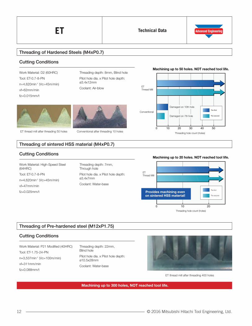
Threading of Hardened Steels (M4xP0.7)
Threading of sintered HSS material (M4xP0.7)
Threading of Pre-hardened steel (M12xP1.75)
Work Material: D2 (60HRC)
Tool: ET-0.7-8-PN
n=4,620min-1 (Vc=45m/min)
vf=62mm/min
fz=0.015mm/t
Threading depth: 8mm, Blind hole
Pilot hole dia. x Pilot hole depth: ø3.4x12mm
Coolant: Air-blow
Work Material: High-Speed Steel (64HRC)
Tool: ET-0.7-8-PN
n=4,620min-1 (Vc=45m/min)
vf=47mm/min
fz=0.025mm/t
Threading depth: 7mm, Through hole
Pilot hole dia. x Pilot hole depth: ø3.4x7mm
Coolant: Water-base
Work Material: P21 Modified (40HRC)
Tool: ET-1.75-24-PN
n=3,537min-1 (Vc=100m/min)
vf=311mm/min
fz=0.088mm/t
Threading depth: 22mm, Blind hole
Pilot hole dia. x Pilot hole depth: ø10.5x28mm
Coolant: Water-base
ET thread mill after threading 50 holes
ET thread mill after threading 400 holes
Conventional after threading 10 holes摩耗幅=0.3mm
Threading hole count (holes)
ETThread Mill
Conventional
0 10 20 30 40 50
The first
The second
Machining up to 50 holes. NOT reached tool life.
Damaged on 10th hole
Damaged on 7th hole
Threading hole count (holes)
ETThread Mill
0 10 20
Machining up to 20 holes. NOT reached tool life.
The first
The second
Provides machining evenon sintered HSS material!
Cutting Conditions
Cutting Conditions
Cutting Conditions
Machining up to 300 holes, NOT reached tool life.
13© 2016 Mitsubishi Hitachi Tool Engineering, Ltd.
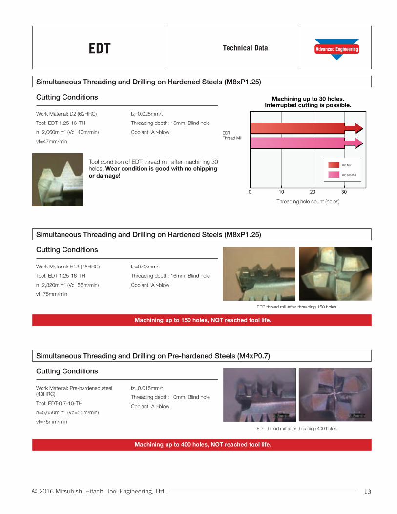
EDT Technical Data
0 10 20 30
Machining up to 30 holes.Interrupted cutting is possible.
Threading hole count (holes)
EDTThread Mill
The first
The second
Simultaneous Threading and Drilling on Hardened Steels (M8xP1.25)
Simultaneous Threading and Drilling on Hardened Steels (M8xP1.25)
Simultaneous Threading and Drilling on Pre-hardened Steels (M4xP0.7)
Work Material: D2 (62HRC)
Tool: EDT-1.25-16-TH
n=2,060min-1 (Vc=40m/min)
vf=47mm/min
fz=0.025mm/t
Threading depth: 15mm, Blind hole
Coolant: Air-blow
Work Material: H13 (45HRC)
Tool: EDT-1.25-16-TH
n=2,820min-1 (Vc=55m/min)
vf=75mm/min
fz=0.03mm/t
Threading depth: 16mm, Blind hole
Coolant: Air-blow
Work Material: Pre-hardened steel (40HRC)
Tool: EDT-0.7-10-TH
n=5,650min-1 (Vc=55m/min)
vf=75mm/min
fz=0.015mm/t
Threading depth: 10mm, Blind hole
Coolant: Air-blow
Tool condition of EDT thread mill after machining 30 holes. Wear condition is good with no chipping or damage!
Cutting Conditions
Cutting Conditions
Cutting Conditions
Machining up to 150 holes, NOT reached tool life.
Machining up to 400 holes, NOT reached tool life.
EDT thread mill after threading 150 holes.
EDT thread mill after threading 400 holes.

© 2016 Mitsubishi Hitachi Tool Engineering, Ltd.14
TroubleshootingET/EDT
Regarding Thread Diameter Expansion/Contraction
Dimensional Accuracy Worsens When Moving Toward the Bottom of the Hole (Deflection)
Regarding Tool Breakage
NC Program Created by Hitachi Tool’s NC Program Creation Software Doesn’t Work Properly
Regarding Upper Limit on Machinable Thread Diameters
Suitable tool diameter compensation should be performed according to the work material and tool wear condition. Also, please be careful not to forget to input the tool diameter compensation value into the machine.
For information about diameter correction, refer to the Cutting Considerations on page 15.
A characteristic of the thread milling method is that tool deflection increases as the tool progresses toward the bottom of the hole. It may be necessary to perform zero cutting in order to perform high-accuracy thread milling with low deflection.
As a countermeasure against tool breakage, performing processing with a reduced feed rate is effective. In addition, when processing with tool extended or when large rough cutting chips are produced, breakage due to chip clogging should be considered. In such cases, if processing is performed with a higher cutting speed, the cutting chips will be broken into smaller bits which may improve conditions.
Changes in cutting chip conditions due to different cutting speeds Simultaneous boring and thread milling (M8 × P1.25) of carbon steel)
There are differences in the programming code for the machine being used. Please contact the machine manufacturer for details.
Please note that since the Epoch D Thread Mill performs boring simultaneously, it cannot perform thread milling for diameters of more than 1.68 times the tool diameter Dc. There are no particular similar limitations on using the ET mill.
Cutting SpeedLow High

15© 2016 Mitsubishi Hitachi Tool Engineering, Ltd.
CuttingConsiderationsET/EDT
About tool feed rate
About tool diameter correction
About coolant
When performing thread milling by helical interpolation, the cutting point feed rate should be multiplied by a coefficient to determine the tool center feed rate. The equation for calculating the tool center feed rate is shown at right.
When performing thread milling by helical interpolation, it may be necessary to compensate for increased cutting resistance due to differences in work materials or tool wear condition. In the NC programs created using Hitachi Tool’s NC program creation software, tool diameter compensation is in radius designation format.
Correction example: Threading of hardened material (60HRC) (M8xP1.25)
Work material: D2 (60HRC) Tool: ET-1.25-20-PN Pilot Hole Dia: ø6.2 Pilot hole depth: ø6.8x25mm
n=2,060min-1 vc=40m/min vf=56mm/min fz=0.03mm/t Threading depth: 20mm
Threading hole count (holes) 10 20 30 40
Tool dia. correction value (mm) 3.09 3.08 3.06 3.04
• When using coolant, air blower is recommended. Water-soluble cutting fluids are suitable for some work materials or improving the grade of processed surfaces. Oil-based cutting fluids are not suitable because they degrade chip removal characteristics.
• The holder should grip the tool shank so that the holder does not block the hole. The shank projection amount is 1 to 2 times the shank diameter. The coolant nozzle should be positioned so that the coolant will reach the bottom of the hole. In addition, coolant pressure should be adjusted so that it removes cutting chips. If the setting is bad, cutting chip clogging may lead to flute tip damage or tool breakage.
• Since there is a risk of cutting chips getting inside the machine, when using tools equipped with oil holes, be sure to perform processing using the oil holes.
vf= fz×z×n× D1D1-Dc
v f Feed rate (mm/min)
fz Feed per tooth (mm/t)
z No. of flutes
n Rotation (min -1)
D1 Thread dia. (mm)
Dc Tool diameter (mm)
1 to 2 timesshank diameter
Not reached tool life.