solid freeform fabrication using the wirefeed process freeform fabrication using ... understand the...
TRANSCRIPT
SOLID FREEFORM FABRICATION USING WIREFEED PROCESS
Griffith, M. T.B. Crenshaw,
L. Greene, Reckaway, J. Romero,D. Harwell, T. E. Buchheit, and V. Tikare
Sandia National LaboratoriesAlbuquerque, NM 87185
Abstract
Direct metal deposition technologies produce complex, near net shape components fromsolid models. Most of these techniques fabricate a component by melting powder in a laser
weld pool, rastering this weld bead to form a layer, and additively constructing subsequent layers.talk will describe a new direct metal deposition process, known as WireFeed, whereby a
small diameter wire is used instead of powder as the feed material to fabricate components.Currently, parts are being fabricated from stainless steel. Microscopy studies show the WireFeedparts to be fully dense with fine microstructural features. mechanical tests show stainless
parts to good strength values with retained ductility.
Introduction
Laser processing has the potential for revolutionizing the rapid prototyping field to impactrapid manufacturing of metallic components. Various groups are coupling high power laserswith metal powders to fabricate Inetallic components, layer additively (1-4). Typically, a laserbeam is focused onto a substrate to create a molten pool into which powder particles are injectedto build up each layer. The substrate is moved beneath the laser beam to deposit a thin crosssection of the desired geometry. Subsequent layers are additively fabricated, thereby building athree dimensional (3-D) component.
While metallic powders work well for described direct metal deposition technologies,they do have drawbacks. A key aspect is material or powder utilization. Typical systems requirea high velocity spray of powder to insure consistent build up; however, only a smallamount of the powder is actually retained in the molten pool, approximately 20%. theWireFeed process, powder is replaced with wire feedstock to fabricate components. With wirefeedstock, 100% utilization is achieved during fabrication, since all wire injected into the moltenpool is used to fabricate the part. Therefore no recycling system is required and faster buildtimes can be accommodated. Furthermore, even flow of the powder material is crucial to thesuccess of fabrication in laser/powder technologies, where control can be difficult to maintain. Itis relatively simple to maintain constant wire feed rates. Another consideration is availability ofmaterial; many materials are readily available in wire form. Direct metal deposition withpowder feedstock requires a good powder source, where size distribution and composition must
529

be carefully controlled. This paper will describe the WireFeed process, the resultant materialproperties for as-processed 308L and 304L stainless steel, and modeling results of themicrostructural evolution.
WireFeed Process
Figure 1 shows a schematic of the initial prototype WireFeed system. systemconsists of a CW 600W Nd:YAG laser, a 4-axis computer controlled positioning system, and awire feed unit (5). The positioning system and wire feed unit are mounted inside a box withlocalized gas purge capability. During fabrication, the workpiece and surrounding area arepurged with argon to minimize oxidation of the workpiece. The laser beam is brought into thebox through a window mounted on the top of the box and directed to the deposition region usinga six inch focal length lens. wire feed unit is designed to inject wire into the molten poolfrom one side, and the lens and wire feed unit move as an integral subsystem.
One Laser Beam
Z-axis Positioningfor Focusing Unit
and Wire Delivery1
x-Y Positioning
Figure 1: Schematic the prototypeWireFeed system showing perpendicularto feed side.
Three Laser Beams
1
Figure 2: Schematic of improvedsystem with three laser beams at1200 placement surrounding wire.
Geometries are written into a series of tool path patterns to build each layer. This file iscombined with other commands to drive the laser, the positioning stages, and the wire feed unitto produce the desired component one layer at a time, starting from the bottom of the part. Asolid substtate used as a base for building the WireFeed object. The laser beam is focusedonto the substrate to create a weld pool in which fine wire is injected, typically 250 microndiameter. The substrate is moved beneath the laser beam to deposit a thin cross section, therebycreating the desired geometry each layer. After deposition of each layer, the wire feedmechanism and focusing assembly are incremented in the positive Z-direction, building a threedimensional component layer additively.
530

Shape
Initially, test matrices were developed and implemented to identify the key factorscontrolling the WireFeed process. The key processing variables include: laser power, wire feedrate, wire feed direction and angle, and traverse velocity. From previous work with LENS (6),laser power, wire feed rate, and traverse velocity are the key factors to control deposition in directmetal fabrication. Along with those tests, extra experimental studies were required tounderstand the relationship between the wire and the weld pool for the system shown in 1.This study included varying the wire feed direction, wire feed height (w.r.t. the substrate), andinsertion angle. Diagnostic tools, such as high magnification video camera techniques, wereused to monitor and understand the wire/molten pool interaction.
From these studies, it was determined that the wire must intersect the molten pool in sucha manner to maintain stability along the solidification front. lfthe wire is inserted too high (w.r.t.the substrate or previous layer), it does not remain connected with the pool; the wire isinserted too low, the wire either stubs on the substrate/layer or is pushed around by the force ofthe weld pool. After choosing the intersection point, the insertion angle and direction must bedetermined. An insertion angle of 45 degrees maintains the best stability, and uniform depositionis only maintained with wire insertion perpendicular to the deposition direction.consistency of build is not maintained if the wire is inserted either from the trailing or leadingedge of the weld pool, because the molten pool has difficulty forming and maintaining beadas the source material or energy moves away.
Since the process was highly dependent on the position of the wire in relation to thedeposition direction, a new system was configured to remove this geometric processingconstraint. As shown in Figure 2, the wire is fed down the center and the laser beam is split intothree beams (by use of fiber optics) to surround the wire. laser heads are stationed 120degrees apart from each other. Now, the wire always enters the pool at the spot' and thereare no constraints on direction of travel. This new design was imperative complex partfabrication.
From the process variable experiments, the laser wire deposition parameters wereoptimized to demonstrate feasibility of part fabrication. Test matrices were added to understandhow layer thickness and hatch (fill) spacing affected part fabrication. Process studies to controlthe wire feed during layer increments for simple block shapes were a major activity. After alayer is fabricated in a serpentine draw pattern, the laser shutter closes, and the focusing and wirefeed subsystems must increment in the positive Z direction to fabricate the next layer. Before theZ increment, the wire must reliably detach from the part. This knowledge is required forcomplex part fabrication with increasing area complexity.
Various shapes with increasing complexity are shown Figure We have fabricatedfour types of geometries: 1) uni-directional fabrication using a rotary stage to build hollowcylinders (Figure 3a), 2) bi-directional patterns to fabricate walls, and 3) with an understandingof wire detachment, hatch spacing and layer thickness, it was possible to fabricate dense,rectangular shapes from 308L stainless steel (Figure 3b). Finally, we have initiated complex part
531

fabrication with the challenge of building two cubes, where each layer is deposited side by side(Figure 3c). This was only possible with the new WireFeed system design shown in Figure 2.All shapes possess 100% utilization of the wire, where the material inserted into the molten poolis directly used to produce a part. WireFeed parts are quickly fabricated, between 0.5 to 1 hourper cubic inch.
(a) (b)
(c)
Figure 3: (a) cross-sectional micrograph of uni-directional fabrication, (b)block fabrication with wire detachment between layers, and (c) complex partfabrication with start and stop capability in each layer.
Materials Characterization
Mechanical BehaviorCoupons were machined from the as-processed 308L stainless steel for room temperature
tensile testing, where the pull direction is parallel to the build plane in the WireFeed system(longitudinal). All samples had densities greater than 98%. The results for WireFeed-processedmaterial is compared to typical annealed material in Table I. With grain size refinement, theWireFeed material possesses strengths greater than annealed, where the yield strength is 58 ksi ascompared to 35 ksi for the annealed material. However, the ductility remains consistent withelongation values of 65-75%, which are slightly higher than the annealed values (55-65%). Highstrengths and hardness with retained ductility is a good combination for WireFeed-processedmaterial.
532
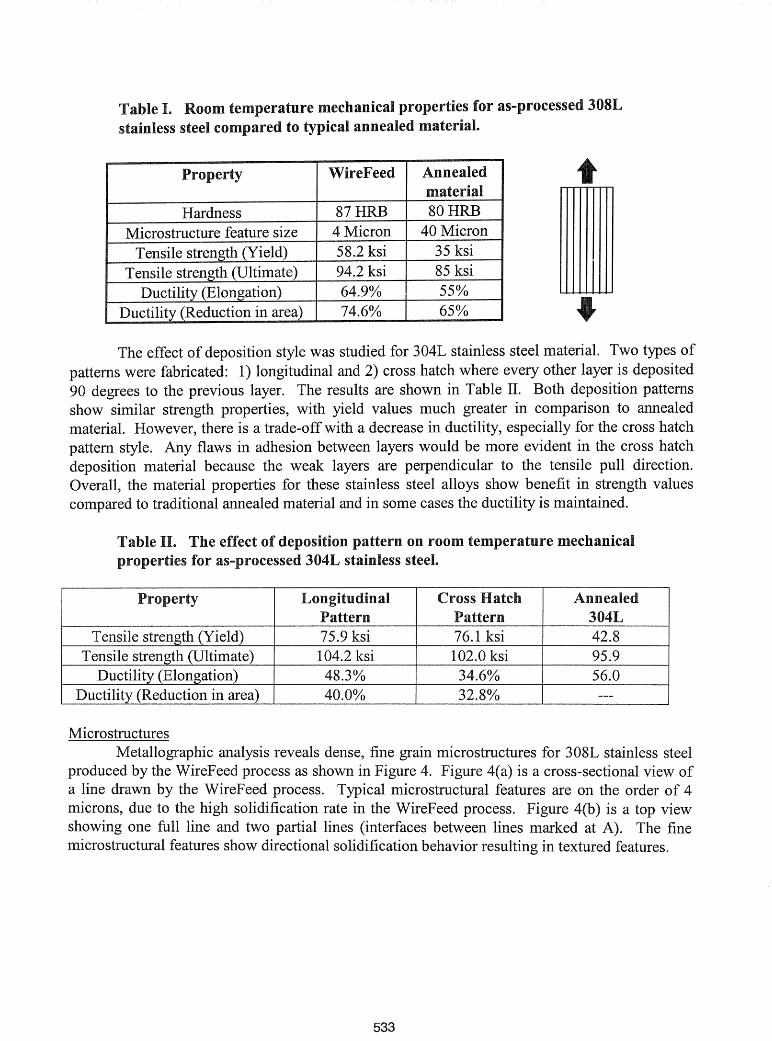
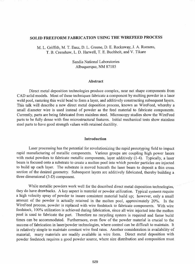
Table I. Room temperature mechanical properties for as-processed 308Lstainless steel compared to typical annealed material.
Property WireFeed Annealedmaterial
Hardness 87HRB 80HRBMicrostructure feature size 4 Micron 40 Micron
Tensile strength (Yield) 58.2 ksi 35 ksiTensile strength (Ultimate) 94.2 ksi 85 ksi
Ductility (Elongation) 64.9% 55%Ductility (Reduction in area) 74.6% 65%
t
•effect of deposition style was studied for 304L stainless steel material. Two types of
patterns were fabricated: 1) longitudinal and 2) cross hatch where every other layer is deposited90 degrees to the previous layer. The results are shown in Table n. Both deposition patternsshow similar strength properties, with yield values much greater in comparison to annealedmaterial. However, there is a trade-off with a decrease in ductility, especially for the cross hatchpattern style. Any flaws in adhesion between layers would be more evident in the cross hatchdeposition material because the weak layers are perpendicular to the tensile pull direction.Overall, the material properties for these stainless steel alloys show benefit in strength valuescompared to traditional annealed material and in some cases the ductility is maintained.
Table The effect of deposition pattern on room temperature mechanicalproperties for as-processed 304L stainless steel.
In. Longitudinal Cross Hatch Annealedr.nJv~·n..y
Pattern Pattern 304LTensile strength (Yield) 75.9 ksi 76.1 ksi 42.8
Tensile strength (Ultimate) 104.2 ksi 102.0 ksi 95.9Ductility (Elongation) 48.3% 34.6% 56.0
Ductility (Reduction in area) 40.0% 32.8%
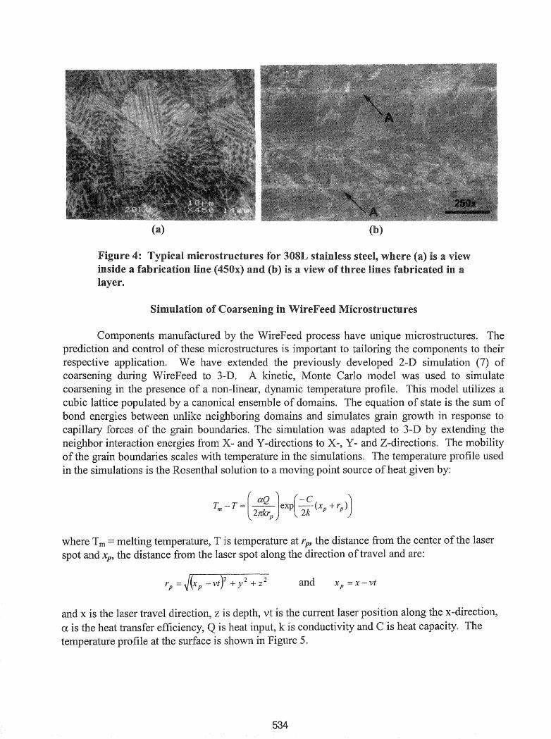
MicrostructuresMetallographic analysis reveals dense, fine grain microstructures for 308L stainless steel
produced by the WireFeed process as shown in Figure 4. Figure 4(a) is a cross-sectional view ofa line drawn by the WireFeed process. Typical microstructural features are on the order of 4microns, due to the high solidification rate in the WireFeed process. Figure 4(b) is a top viewshowing one full line and two partial lines (interfaces between lines marked at A). The finemicrostructural features show directional solidification behavior resulting in textured features.
533
center
X p = x vt

(a) (b)
.nr1ll"'c'lIn~ at two laser velocities:'IlJllTII1l.D1II"'£lI MCS Monte Step).
535
Conclusions
With the WireFeed process, high fabrication rates (one hour per cubic inch) can beachieved with 100% utilization of feed material. As-processed stainless steel parts havestrengths greater than traditional annealed material, but with retained ductility if there are noflaws (porosity) during fabrication. Preliminary modeling of the WireFeed process shows thecorrelation between the laser beam profile and raster speed with the resulting microstructure.The WireFeed system is simple in design, requiring only a localized gas purge to removedunwanted oxidation during fabrication. This allows for easy part removal and change of wirematerial. Future work will develop complex geometry fabrication, where the theoretical modelwill be able to predict the resulting microstructure for a given material and process conditions.
References
1. M. L. Griffith et aI., "Free Form Fabrication of Metallic Components using Laser EngineeredNet Shaping (LENS)", Solid Freeform Fabrication Symposium Proceedings, August 12-14, 1996,Austin, TX, p.125.
2. J. R. Fessler et aI., "Laser Deposition ofMetals for Shape Deposition Manufacturing", SolidFreeform Fabrication Symposium Proceedings, August 12-14, 1996, Austin, TX, p. 117.
3. Klocke, Wirtz, and W. Meiners, "Direct Manufacturing ofMetal Prototypes andPrototype Tools", Solid Freeform Fabrication Symposium Proceedings, August 12-14, 1996,Austin, TX, p.141.
4. J. Mazumder et aI., "The Direct Metal Deposition ofH13 Tool Steel for 3-D Components",Journal ofMaterials, Vol 49, Number 5 (1997), p. 55.
5. E. Brandon, F. Hooper, and M. Reichenbach, "Precision Wire Feeder for Small DiameterWire" (U. S. Patent #5137223, August 11, 1992).
6. D. M Keicher et al. , "Towards a Reliable Laser Powder Deposition System through ProcessCharacterization", Proceedings ofSAMPE '95, Albuquerque, NM, October 12-14, 1995, p.1029.
7. V. Tikare et aI., "Simulation of Coarsening during Laser Engineered Net Shaping", SolidFreeform Fabrication Symposium Proceedings, August 11-13, 1997, Austin, TX, p.699.
536