solid propellant gas generators: proceedings of the 1995
TRANSCRIPT

NISTIR 5766
SOLID PROPELLANT GAS GENERATORS:
PROCEEDINGS OF THE 1995 WORKSHOP
Jiann C. Yang and William L. Grosshandler, Editors
November 1995Building and Fire Research LaboratoryNational Institute of Standards and TechnologyGaithersburg, MD 20899
U.S. Department of CommerceRonald H. Brown, SecretaryTechnology AdministrationMary L. Good, Under Secretary for TechnologyNational Institute of Standards and TechnologyArati Prabhakar, Director

DISCLAIMER
The views, comments, suggestions, and recommendations expressed at the workshop and reportedin these proceedings are those of the participants and the editors and do not necessarily reflect those ofthe National Institute of Standards and Technology, which is under no obligation to execute therecommended actions. In addition, certain commercial equipment, instruments, or materials that havebeen identified in this document are included in order to specify experimental procedures adequately, orto demonstrate a type of equipment. Such identification is not intended to imply recommendation orendorsement by the National Institute of Standards and Technology, nor is it intended to imply that thematerials or equipment identified are necessarily the best available for the purpose.

Page
Disclaimer . . . . . . . . . . . . . . . . . . . . . . . . . . . . . . . . . . . . . . . . . . . . . . . . . . . . . . .. ii
Acknowledgment s . . . . . . . . . . . . . . . . . . . . . . . . . . . . . . . . . . . . . . . . . . . . . . . . ..iv
Abstract . . . . . . . . . . . . . . . . . . . . . . . . . . . . . . . . . . . . . . . . . . . . . . . . . . . . . . . . . .V
Introduction . . . . . . . . . . . . . . . . . . . . . . . . . . . . . . . . . . . . . . . . . . . . . . . . . . . . . . .1
Discussionand Conclusions . . . . . . . . . . . . . . . . . . . . . . . . . . . . . . . . . . . . . . . . . . . ..2
Recommendations . . . . . . . . . . . . . . . . . . . . . . . . . . . . . . . . . . . . . . . . . . . . . . . . . ...3
Appendix A
Appendix B
Appendix C
Appendix D
Appendix E
Comments/Suggestions for Future Gas Generator RelatedR& Dfrom Workshop Participants . . . . . . . . . . . . . . . . . . . . . . . . . . . ...5
Solid Propellant Gas Generators:An Overview and Their Application to Fire Suppression . . . . . . . . . . . . . . . . 15
List ofParticipants . . . . . . . . . . . . . . . . . . . . . . . . . . . . . . . . . . . . . ...18
Meeting Agenda . . . . . . . . . . . . . . . . . . . . . . . . . . . . . . . . . . . . . . . ...22
Workshop Presentations . . . . . . . . . . . . . . . . . . . . . . . . . . . . . . . . . . ...25Introducto~Remarks, JiannC. Yang . . . . . . . . . . . . . . . . . . . . . . . . . ...26Fundamentals ofSolid Propellant Combustion, Kenneth lK.Kuo . . . . . . . . . . . . 32Fire Extinguishing Pyrotechnics, James Hoover etal. . . . . . . . . . . , . . . . . . . 75iWodeling andExperimental Validation ofpyrotechnic Gas Generators,
Herman Krierand P. Barry Butler. . . . . . . . . . . . . . . . . . . . . . . . .89Aspects ofFlame Suppression, Anthony Hamins . . . . . . . . . . . . . . . . . . . . . 123S“eciesConcentrationM easurements, Williamm M. Pitts . . . . . . . . . . . . . . . 147Oqgen Concentration Memurements ming Diode bers, David Borne . . . . . . 173USAF SPGGAdvanced Development Program, Mark Gillespie . . . . . . . . . . . 183Inert Gas Generators Usedfor Fire Protection Aboard Nayy Aircra$!,
Marco Tedeschi . . . . . . . . . . . . . . . . . . . . . . . . . . . . . . . . . . ..190Navy Qualification ofSolid Propellant Gas Generators
for Aircra~Fire Suppression, Philip Renn . . . . . . . . . . . . . . . . . . . 198Explosion Suppression for Industrial Applications, Francesco Tamanini . . . . . . 208
ACKNOWLEDGMENTS
The editors would like to express their sincere gratitude to all the speakers (in alphabetical order)whose presentations and participation have made this workshop a successful event: Dr. David Bomse(Southwest Sciences, Inc.), Professor Barry Butler (University of Iowa), Lt. Mark Gillespie (U.S. AirForce Wright Laboratory), Dr. Anthony Hamins (BFRL/NIST), Dr. James Hoover (NAWC, ChinaLake), Professor Herman Krier (University of Illinois), Professor Kermeth K. Kuo (Pennsylvania StateUniversity), Dr. William Pitts (BFRL/NIST), Mr. Philip Renn (NSWC, Indian Head), Dr. FrancescoTamanini (Factory Mutual Research Corporation), and Mr. Marco Tedeschi (NAWC, Lakehurst). Theeditors would also like to thank Ms. Paula Garrett for her relentless effort in organizing this workshop,Dr. Jack Snell, Fire Program Manager of BFRL/NIST, for the official welcome, despite his busyschedule, Dr. Richard G. Gann, Chief, Fire Science Division, for providing advice in organizing andconducting the workshop, their fellow NIST colleagues, and all the workshop participants. The usefulcomments and suggestions provided by many participants were also greatly appreciated.
iv

ABSTRACT
A workshop on solid propellant gas generators was held on June 28-29, 1995 at the NatiomlInstitute of Standards and Technology under the sponsorship of the Building and Fire ResearchLaboratory. Gas generator technology was first proposed as an alternative to halon 1301 (CF~Br) for in-flight fire protection. Because the technology is still in a developing stage as a fire suppression method,there is no standard test apparatus for evaluating the performance of gas generators, and there remainmany unanswered technical questions for the potential users. The specific objectives of the workshopwere (1) to identify certification procedures, (2) to determine which critical parameters were required tocharacterize the performance of a gas generator, (3) to develop a standard test method for gas generatorevaluation, (4) to identify other potential applications, and (5) to search for next generation of propellants.The participants at the workshop included representatives from aircraft and airframe manufacturingindustries, airbag and propellant manufacturers, fire fighting equipment companies, military services,government agencies, and universities. The agenda of the workshop encompassed eleven presentationson various topics relevant to the applications of gas generators as afire fighting tool, followed by severaldiscussion sessions. Various important issues related to the achievement of the objectives set forth wereaddressed, and recommendations regarding what role NIST should play in this new technology weresuggested.
v

1995 WORKSHOP ON SOLID PROPELLANT GAS GENERATORS
INTRODUCTION
The rapid phase-out of halon 1301 fire protection systems has accelerated the search for otherpotential technologies as alternate means to suppress fires, Solid propellant gas generators (also knownas fire extinguishing pyrotechnics or flame suppressing gas generators), a spin-off from airbagtechnologies, have recently been demonstrated to suppress certain types of fires, particularly aircraftengine nacelle and dry bay fires. This document summarizes a workshop on solid propellant gasgenerators held at the National Institute of Standards and Technology (NIST) on June 28-29, 1995 underthe auspices of the Building and Fire Research Laboratory.
The intent of the workshop was to bring together gas generator manufacturers, researchers, andpotential users to discuss various critical issues related to the evaluation and performance of the gasgenerators as a fire fighting tool and the search for new propellants. Although standard test apparatusfor evaluating the performance of airbags exist, no such equivalence is currently available for evaluatingfire suppression performance of gas generators due to the infancy of this technology. The specificobjectives of the workshop, which reflected the need for such an apparatus, were:
● identification of certification procedure(s) for gas generators in fire suppressionapplications,
● determination of critical parameters for evaluating the fire suppression efilciency ofvarious gas generators,
● development of a standard methodology to facilitate testing of gas generators,● identification of possible applications other than protection of engine nacelles and dry
bays,● identification of a new generation of propellants.
However, the emphasis was placed on the performance and evaluation aspects because it was notpossible to discuss the search for new propellants in such a format that certain proprietary propellantingredients would not be disclosed and that the manufacturers’ and researchers’ patent-pending rights ofthe new propellants could be protected.
The workshop participants included propellant and airbag manufacturers, airframe and aircraftmanufacturers, military services personnel, researchers from academia, industries, and governmentlaboratories, and potential users.
The agenda of the workshop encompassed presentations on various topics ranging fromcombustion of solid propellants to flame extinction mechanisms, followed by several discussion sessions.The meeting agenda is listed in Appendix D and is briefly summarized as follows. For those who arenot familiar with the gas generator technology, Appendix B, which is an extended abstract presented bythe editors at the 1995 International Conference on Fire Research and Engineering, can serve as anintroduction to the subject.
The meeting started with an official welcome by Dr. Jack Snell who is the Deputy Director andFire Program Manager of the Building and Fire Research Laboratory (BFRL) at NIST. Then, Dr. JiannC. Yang of BFRIJNIST gave a brief overview on the current gas generator technologies for firesuppression. Professor Kenneth K. Kuo of Pennsylvania State University delivered a tutorial onfundamentals of solid propellant combustion. Dr. James Hoover of the Naval Air Warfare Center atChim Lake discussed the Navy’s in-house research program on fire extinguishing pyrotechnics and thefull-scale engine nacelle and dry bay test facilities. Professors Herman Krier of University of Illinois and
1

Barry Butler of University of Iowa presented their research work on modeling of a generic airbag. Dr.Anthony Hamins of BFRL/NIST discussed various aspects of flame suppression. Dr. William Pitts ofBFRL/NIST and Dr. David Bomse of Southwest Sciences, Inc., discussed various species measurementtechniques. Lt. Mark tlllespie of the U.S. Air Force Wright Laboratory and Mr. Marco Tedeschi ofNaval Air Warfare Center at Lakehurst briefed the audience on the current Air Force and Navy gasgenerator programs. Mr. Philip Retm of the Naval Surface Warfare Center at Indian Head discussedvarious gas generator qualification programs. Finally, Dr. Francesco Tamanini of Factory MutualResearch Corporation presented his view on the potential application of gas generator technology toindustrial explosion suppression. Copies of their presentations are included in Appendix E. Some pages,although presented at the workshop, were intentionally left blank by the speakers when they submittedtheir copies to the editors due to the preliminary, sensitive, and proprietary nature of the data. Thesepages were not included in this Appendix.
DISCUSSION AND CONCLUSIONS
There were several discussion sessions at the workshop. The sessions were arranged in such away that various important issues related to the application of this technology could be addressed. Otheruseful comments, suggestions, and feed-back from the participants are included in Appendix A.
It was not apparent from this workshop that other potential applications, except engine nacellesdry bays, and army vehicles, had been identified because potential end-users among the participants werenot broadly represented. For example, representatives from the power utility and telecommunicationindustries were not present in the workshop. Their absence, however, did not reflect their lack of interestin this technology, but rather it was merely the scheduling and the timing of the workshop that precludedthem from attending. It is conceivable that gas generators can be used in a manner similar to a streamingagent for suppressing fires locally or in locations that are difficult to access. Unless sufficient leakageor ventilation is present, total flooding or inerting of an unoccupied space using gas generators may notbe feasible because of over-pressurization. In addition, it is also unlikely that gas generators will be usedfor total flooding in inhabited areas because of complication of possible asphyxiation by inert gases.
Several conceptual designs of test fixtures for evaluating gas generators in fire protectionapplications were proposed, Since the gas generator technology has its genesis from airbag technologies,some of the proposed test fixtures bore resemblance to those used in the evaluation of airbags. The twoapparatus that were discussed the most in the session were several versions of a modified discharge tankand a small-scale wind tunnel. The discharge tank is routinely used in the industry to evaluate theperformance of airbags, and the small-scale wind tunnel in which a pool fire is placed behind a bluff bodyhas been used for screening various halon alternatives. The small-scale wind tunnel set-up mimicked asimulated engine nacelle. The schematics of the proposed test fixtures can be found in Appendix A.
Because a majority of the participants were from the airframe and aircraft industries and gasgenerator technology was first proposed as a halon alternative to be used for in-flight aircraft engine anddry bay fire protection, the discussion at the workshop was heavily concentrated on the technicalproblems that were facing these two applications although similar problems could be encountered whenexploring other potential applications of the gas generators. One discussion session was directed to thearea of measurements for tie purpose of gas generator performance evaluation and certification. Sincethe effluent product gases depend strongly upon the type of propellant used, it is not feasible andeconomical to measure the product gases for any arbitrary propellant using various types of instruments.There was consensus among the participants that monitoring of oxygen concentration was probably themost appropriate way to assess the performance of a gas generator used in a dry bay or engine nacelle.In this way, the dependence of effluent product gases on propellant is eliminated (assuming the gasesgenerated are inert). The issue of response time of the measurement technique was also a subject of
2

lengthy discussion. The requirement of 1 ms or less response time for dry bay applications has presentedsome technical challenges to the researchers. In addition to oxygen concentration measurement, severalother parameters were suggested as useful indicators in the evaluation of gas generators, including:pressure, shock, velocity, and temperature.
It was clear that some of the current airbag models could be modified to evaluate gas generatorperformance. The incorporation of computation fluid dynamics models into the airbag models to studythe interaction of exhaust gases from the generator with the geometry of a protected space was suggested.
There was general agreement among the participants that there is an urgent need to develop acertification procedure before gas generators could be considered as a replacement for halon 1301 inengine nacelle and dry bay applications. The lack of a certification process may hinder the deploymentof this technology in a timely manner despite many successful full-scale engine nacelle and dry bay firetests. Still, how to certify a gas generator had not become apparent at the conclusion of the workshop.The major stumbling block appeared to be the identification of certain critical parameters that wererequired to assess the fire suppression efficiency of an arbitrary gas generator. Such parameters shouldplay important roles in the flame suppression mechanisms. Oxygen concentration emerged as a criticalparameter from the discussion. However, detailed flame suppression studies have to be conducted beforethe role of oxygen in the certification process can be identified.
The lack of a standard laboratory-scale test apparatus for evaluating and screening the firesuppression efllciency of various gas generators may also slowdown the advancement of this technology.A test fixture, whose functions and usefulness will be at least similar to that of a standard cup burner usedfor halon alternative screening studies, needs be developed. The apparatus, in principle, should berelatively simple but at the same time allow enough important information (oxygen concentration,temperature, pressure, etc.) to be obtained so that our understanding of the suppression actions of gasgenerators can be enhanced.
Judging from the responses from the participants during the discussion sessions and theirsubsquent feed-back, the objectives of the workshop set forth were met with varying degrees of success.
RECOMMENDATIONS
In light of the discussion at the workshop and the current status of gas generator technology forfire suppression, the following recommendations were made.
● A standard test fixture for evaluating fire suppression efilciency of gas generators shouldbe developed. NIST is capable of supporting these efforts.
● The identification of a new class of next generation propellants (e.g., cool and highnitrogen content in the effluent) and the characterization of thermophysical properties ofpropellants should remain the realm of propellant manufacturers and researchers becauseof their expertise in this field.
● Certification processes should be developed because they are critical to the advancementof the technology. The development may require extensive cooperation among variousparties and many strategy sessions as more full-scale test results become available. NISTcan act as a coordinator in such an effort, and if deemed necessary, NIST will sponsorworkshops to address the certification issues.
● In view of its involvement in fire modeling and computational fluid dynamics, NISTshould play an active role in the modeling effort to study gas generator performance.
3

e The push for the gas generator technology to other areas of applications requires thepromotion of public awareness of such technology, and in this regard, NIST should bein a favorable position to play such role to identi~ other potential users because of itsconstant communication and interaction with the fire protection community.
4

Comments/Suggestions for Future Gas
(In alphabetical order)Mr. Glerm Harper, McDonnell Douglas
APPENDIX A
Generator Related R & D from Workshop Participants
General: The following suggestiondcornments for future Gas Generator fire fighting R & D have beenprepared as a result of-tie ‘USN and NIST sponsored workshops at NIST in J~e i995. The primaryrequirements appear to be: understanding the extinguishing mechanisms, defining theconcentration/distribution us. time, simplified modeling to gain insight into concentration/distribution,verification of the applicability of small scale lab tests, additional applications, prioritizatiordallocationof R & D funds, and adequate interaction of the various interested parties. There appear to be twoprimary goals: understanding the process, and developing reasonably accurate engineering prediction toolsfor each technology in order to select the optimum technologies for deployment.
(1) Gas Generator Combustion: There was much discussion regarding the need for detailed research intothe combustion process inside the generator. Although there is always more to learn about this process,much more is known about this subject than about hot inert gas distribution or the extinguishingmechanism. Future R & D should concentrate on the issues least understood because those are the areasof greatest risk.
(2) Extimzuishing Mechanism: The F/A-18 E/F Engine Bay fire extinguishing tests at China Lake in1994, though successful, are not fully understood. The first priority for future Gas Generator R & Dshould be to better understand the fire extinguishing phenomenon for those series of tests and also forthe Dry Bay tests. To this end I suggest the following for all future Engine Bay testing until the processis well understood:
(a) Continue to push for the 100 ms response concentration sensor ASAP, for the 1995 V-22 testsif possible. If the local concentration of inert gases in the area of the fire are well below theminimum inerting concentrations, then the mechanism is not inerting and other measurementsmust be made to determine how the fire is extinguished. I would even accept slower responseif that was all that was available. (This conclusion presumes that the 100 ma response time isadequate, which may be a false assumption.)
(b) Insure good time correlation between the video coverage and the extinguishing sequence.
(c) If possible, install high response instrumentation in the area of the fire to record pressures,temperature, velocity, flow direction, etc. Enough instrumentation to determine the extinguishingmechanism(s) should be installed if at all possible.
(d) If possible, instrument to sense a shock in the area of the fire.
(3) Concentration Sensor: 02 sensing, over a broad range of concentrations, is preferred since the samedevice could then be used for any agent or generator; however, if sensing Oz is much less sensitive, takesmuch longer to develop, or cost much more, it might be preferable to sense some other gases, especiallyfor the near term testing. The 100 ms response seems fast enough to learn a lot about distribution in thenext test series, especially since it is the only system currently available. Faster might be better but if
5

it is too late it is of no value. A study to really determine the required response time assuming bothinerting and mechanical extinguishing might be valuable since current estimates seem to be based moreon experience than analysis. We may need the 1 ms system for Dry Bay ballistic testing and even thatmay not be adequate.
(4) Modelin% There appears to be a real need for appropriate modeling to better understand thedistribution process, to resolve the wide variation in test results between test site, and the ability to makereasonably accurate engineering predictions for sizing and trade studies. A simplified model that allowsone to look at the general trends and provides ROM values is much more valuable now than a detailedCFD model that provides high accuracy but takes several man years to develop. A simplified modelbased on first order effects to address mixing, cooling, buoyancy, ventilation, transport time, etc. wouldbe very helpful in all future Engine Bay testing, this fall if possible. (I would like to see the results ofNIST modeling for Mr. Mike Bemett when they become available.) Perhaps a more complex CFDmodel could be developed to provide insight as a research tool, but if it takes as much time as Dr. Krierindicated it will be of little or no help to the industry. This is another area where the appropriate balanceof resources is required. We must have some modeling, but determining the appropriate levels ofexpenditure, accuracy, and detail is the challenge.
(5) Small Scale Tests: The discussion of the Turbulent Spray Burner and the Turbulent Pool Burner (Ibelieve Dr. Hamins used different names.) test results were interesting. I think working with MikeBennett and NAVAIR to veri~ the applicability of these test approaches for evaluating both chemicalagents and, if possible, adapting them to Gas Generators would be helpfil in quickly developing andevaluating new propellants. In reality, most Engine Bay fires are a combination of both spray and poolfires and combining the results of both tests may provide the best correlation with full scale tests.
(6) Other Applications: There are likely to be applications for Gas Generators for fuel tank protectionand perhaps for weapons bay protection, although one should check with the U. S, Army first to see theresults of their ammunition bay testing.
(7) Broad Interaction: I encourage NIST to insure that the research/academic organizations involved inNIST out year programs have a mechanism in place to insure adequate interaction with the airframe,engine, fire extinguishing, government pyrotectilc, and Survivability & Vulnerability (S & V)communities to insure their R & D activities can be applied to our specific areas of concern in a timelymanner with appropriate limits on the levels of complexity, effort, and accuracy.
(8) Prioritization: I encourage NIST to resist spending a disproportionate amount of NIST limitedresources in detailed research on things already fairly well understood (Combustion inside the Generatorfor example.) as opposed to gaining insight into those areas about which little is known (Extinguishingmechanism or distribution of effluent gases thorough the bay for example.). it is better to obtain the first50 % knowledge in an unknown area than the last 5 % knowledge in an area already fairly well explored.
(9) Other Issues: The impact of discharging Gas Generators into Engine Bays containing engines worth$3 to $10 roil. must continue to be considered. Clean-up, corrosion (especially in salt atmosphere,landing after post-shutdown cold soak, etc.), the “Blast Effect” on maintenance crews if accidentaldischarged, toxicity all need to be considered. Testing over broad range of temperatures, vibration/shock,etc. is also required since the combustion characteristics of all propellants are temperature dependent,some more than others, and there is some risk of “cracked grains” due to shock, temperature cycling,vibration, etc. which may result in severe over pressure when ignited.
6

Dr. J.M. Heimerl, Army Research Laboratory
A Method to Attack Practical Extimmishment Problems
The flow diagram of Dr. Bill Grosshandler and the “living room” fire schematic of Prof. HerrnanKrier suggested the methodology to be discussed below.
Bill Grosshandler suggested that the overall problem could be broken down into a series of eventssuch as:
Gas Generator = spatial & temporal flow= fire extinguishment.
Herrnan Krier presented a “living room” fire as an example of the complexities of a real life firescemrio.
The fire, F, is to be put out by the gas generator GG. There is some complex flow path that theextinguishing gases must take to reach the fire.
The proposed methodology isolates the fire from the rest of the environment and divides theoriginal problem into two parts.
(1) Isolate the fire by inscribing a boundary, B.
Determine what values (or range of values) of critical parameters must be present at B to extinguish thefire. The parameters might include: temperature, pressure, species concentration (e.g., diluent or“superagent”), and flow velocity. The extinguishing properties could be determined from experiment,modeling, or previous experience.

(2) Then, other flow codes (or perhaps, even experiments) could be used to determine the values of theparameters at the boundary, B,
and answer:
(1) whether the given, fixed GG could extinguish the flame, F (this answer relates to drop-inreplacement for a current halogen extinguisher); or
(2) what arrangement of GG (i. e., type of solid propellant, amount per container, number ofcontainers, their locations) would extinguish P, or
(3) what, is the best arrangement (e.g., with cost, time or total amount of propellant asconstraints) to extinguish F.
The advantages of this methodology are:
(1) it separates the system and its fire from the environment that contains the gas generator. Tohandle them together, either experimentally or in a code, can be a complex, expensiveundertaking.
(2) it allows the user (of the system to be protected) to define the problem in a way that allowsa relatively rapid solution. Detailed specifications of the system need not be present in codes(or experiments) employed to determine solution.
(3) even if the fire is so large or so hot that it strongly couples with and severely affects the flowcontours in the surrounding environment, the methodology might still be useful if one were toinclude in the model a “black box” heat source bounded by B.
One might think that a possible disadvantage of this methodology is the requirement the valuesof the critical parameters at B must be known. This may prove to be difficult in practice. However, onewould have to know this information (or its equivalent) to determine whether GG is solution.
8

Prof. Herman Krier, University of Illinois, Urbana-ChampaignProf. Barry Butler, University of Iowa
Kev Conce~ts for Modeling Strategies
●
●
●
●
●
●
Solid Propellant Gas Generator models exist, have been validated, and can be applied to “new”systems.
IllJ&t QIQQl!I
* Propellant information * Mass flow (t)* Hardware parameters * Velocity (t)* Combustion behavior * Temperature (t)
● * Species concentration (t)● ●
● ●
etc. etc.
Fires to be extinguished are flow specific (i. e., wide variety of different flow conditions).
* Geometry (engine mcelles vs. dry bays vs. others)* In-flow/out-flow* Chemistry of flame (Darnkohler number)
●
●
etc.
The @is input to the second (gas generator output is choked flow).
CFD codes for chemically reacting, high turbulence flow exist and are routinely used.
Based on combustion fundamentals, criteria for extinguishment must be specified.
Solve the 2-D, unsteady, chemically reacting flow specific to each “problem”.
* Cold flOW
* Hot flOW

Modified Tank Test
KSpecies i
Yi T
02
t
e Small scalee Fundamental understanding - Yese Product development - Yese Certification - Noo Inexpensive - Yese Repeatable - Yes
/
t
10

A Potential Test Fixture
Solid propellant gas generator
\
Igniter /
Pre-pressurized “chemically active suppression gas”or N2
Test tank(volume variable)
+
Fuel in
7
11

.
Mgas generator
.
M gas generator&: <<< 1.
M air
12

DRYBAYFIRE
Gas generator
M (t), T(t), V(t), Yi (t)
13

Prof. Kenneth K. Kuo, Pennsylvania State University
Fundamental Data Recwired
e Characterization of gas generator propellant burning behavior including:
~ Steady-state burning rate and product concentration
* r~ = r~ (P,~)* Burning surface temperature, T, = T, (P,~)* Temperature sensitivity, aP = OP(P)* Combustion product concentration
e Transient burning behavior
* The effect of chamber pressure variations on burning rate* Characterization of pertinent combustion instability parameters such as
(~TjdZ)F, acoustic admittance, etc.
Contributions from Participants in the Discussion Session moderated by Dr. William M. Pitts, NISI’
Parameters of interest
oeeoe@eeo
Shock measurementsVeloci~PressureConcentrationTemperatureFlow visualizationRadicalsFlame/flow interactionThermal cooling
14
——

Solid Propellant Gas Generators: An Overview and Their Application to Fire Suppression
Jiann C. Yang and William L. Grosshandler
Building and Fire Research LaboratoryNational Institute of Standards and Technology
Gaithersburg, Maryland 20899 U.S.A.
ABSTRACT
A solid propellant gas generator is essentially an airbag inflator without a bag. That is, the gas generatedis discharged directly into ambience rather than into a bag. A typical solid propellant gas generatorconsists of solid propellant tablets which will, upon ignition, rapidly react to generate gas-phasecombustion products and particulate, an igniter to initiate the combustion of the propellant, a filtersystem to prevent or minimize the release of the particulate from the combustion reactions into theambience, a heat transfer mechanism (normally the filter itself) to cool the high temperature combustiongas before being discharged into the ambience, and an exhaust mechanism to disperse the gas efllciently.In this article, an overview of the current status on solid propellant gas generators will be discussed, andpotential areas for future research will be suggested.
The solid propellant used in an airbag inflator typically contains sodium azide (NaN~), iron oxide (Fe@q),and small amount of other proprietary additives. The principle gas-phase product as the result of thecombustion of the NaNg/F~O~ propellant is nitrogen, and the resulting temperature is in the neighborhoodof 1300 K. Solid species such as sodium oxide (NzO) and ferrous oxide (FeO) are also generated duringthe combustion process. Since the product gas is mainly nitrogen, the extension of airbag inflatortechnologies to suppress fires is ideal and logical. The suppression action of a solid propellant gasgenerator is believed to be due mainly to the effects of oxygen displacement (dilution) by nitrogen andgas discharge dynamics (flame stretch). To a lesser extent, a thermal effect also plays a role. However,the actual extinguishment mechanism(s) are not precisely known. It is possible that the extinguishmentmechanism depends on the distance between the gas generator and the fire. If the location of the gasgenerator is very close to the fire, the extinguishment mechanism is likely to be attributable to blowingout the fire by the exhaust from the gas generator.
There are basically two types of airbag inflator systems: (1) the conventional and (2) the pre-pressurizedor gas-assisted. In a conventional system, the gas that is used to inflate the bag depends entirely on thecombustion gas generated by the solid propellant. However, in a pre-pressurized or gas-assisted system,the high temperature gas as a result of the combustion of the propellant is first mixed with a pre-pressurized inert gas at ambient temperature before being discharged into a bag. Similarly, one can alsoconveniently classi@ solid propellant gas generators into two categories, depending upon their functions:(1) conventional and (2) hybrid. When a gas generator is used alone for fire suppression, it is termed
lpresented at the 1995 International Conference on Fire Research & Engineering, September 10-15,Orlando, Florida
15

“conventional.” When it is used together with other liquid or powdered fire suppressing agents, it istermed “hybrid.” In a hybrid system, the gas generator normally is used as a means to provide sufficientpressurization so that the expulsion of liquid or powdered agent from a storage vessel can be facilitated.
A typical sequence of events that occurs during gas generation for fire suppression using solid propellantscan be described as follows. Upon detection of a fire, the igniter located in the combustion chamber ofthe solid propellant gas generator is activated. The igniter, which contains a small amount of pyrotechnicmaterials (e.g., Zr/KCIOq), immediately releases high temperature gas and hot particulate via thermallyinitiated, exothermic chemical reactions of the pyrotechnic materials. The resulting temperature andpressure rises then initiate the solid propellant reactions near the igniter, and a deflagration front rapidlypropagates throughout the solid propellant bed. Very frequently, booster propellants, ignited by theigniter, are used to facilitate the combustion of the main solid propellants. The high temperature andhigh pressure combustion gases, together with the condensed-phase products, then exit the combustionchamber through a filter before discharging into the ambience.
The attractiveness of using solid propellant gas generators in fire suppression applications lies in the factthat the system, when used alone, is considered to have no ozone depletion and global warming potential,and is physically very compact. Being a derivative from the airbag inflator technologies, there arevoluminous research materials available in the literature. Another advantage is that since gases aregenerated via solid propellant reactions, the system can, in principle, be tailored to fimction over a periodof few milliseconds (e.g., for aircraft dry bay fire protection) to few seconds (e.g., for aircraft enginenacelle applications) by manipulating the parameters that control the combustion mechanisms. Inaddition, the gas generators have very extended storage and service life. However, the toxicity of someof the by-products can not be ignored.
A review of previous research literature on airbag inflator technologies has suggested, throughparallelism, the following areas for titure research on solid propellant gas generators: (1) continuingsearch for better solid propellants, (2) better understanding of the suppression mechanism(s) of theproduct gases, (3) modeling and simulation of the thermochemistry and gas discharge d~amics, and (4)hardware optimization.
Sodium azide, which is used in the preparation of herbicides and in various organic syntheses, is thecurrent principal chemical used in solid propellants for gas generators. Because of its potential healthhazards (e.g., its potential to lower blood pressure), current research has been focused on the “non-azidebased” propellants by the airbag manufacturers. The pertinent thermochemical and thermophysicalproperties to be considered for any new propellant should include (1) propellant thermochemistry (flametemperature and chemical composition of combustion products) and stoichiometry (moles of gas producedper mole of propellant burnt), (2) propellant ignitability and burning rates under various conditions, (3)toxicity of combustion products, (4) stability of propellant during storage and transport, and (5) propellantthermal properties. In addition, the grain size and shape of the propellant and how the propellant ispacked in the gas generator also play important roles in the performance of the gas generator.The suppression mechanisms of the combustion gases are the least understood because of the complexityof the gas discharge dynamics and turbulence interaction of the suppressants with the fires. Currentpractice for studying the suppression efficiency of the propellent, at least in the dry bay and enginenacelle applications, is to use trial and error to determine the amount of propellants required to put outa specific fire. Abetter understanding of the suppression mechanisms would therefore be needed in orderto determine the required amount of propellants in a systematic way.
16

Current computer codes for simulating airbag inflator performance maybe used with some modificationsto evaluate the performance of gas generators. Note that existing computer codes address almostexclusively the simulation of internal performance of airbag inflators and that chemical equilibrium isassumed to determine the products of combustion and flame temperatures. Since the gas generationprocesses are extremely rapid and over in such a short duration, chemical equilibrium may not bereached, and simplified or detailed chemical kinetics should be considered in future code development.In addition, the interaction of the exhaust gas from the gas generator with the ambience has to be takeninto account in the modified codes.
Current or future airbag inflator technologies can definitively benefit the hardware optimization of gasgenerators. Current active areas of research on airbag inflator hardware appear to be focused on theimprovement of filter design and gas cooling system. For solid propellant gas generators, research shouldalso be focused on how to disperse the gas effectively upon leaving the generator.
Presently, the gas generator technique has been proposed to be used in uninhabited areas because of thedetrimental effects of oxygen depletion and nitrogen inerting on humans. Current interest has beenfocused on the application of the technique to aircraft dry bay and engine nacelle fires. Recently, testsperformed at the Naval Air Warfare Center in China Lake, California and Wright Laboratory in Dayton,Ohio have demonstrated the feasibility of using solid propellant gas generators to suppress simulatedaircraft dry bay fires. Other potential areas of application have also been suggested by the manufacturers.These include, to name a few, warehouse fire protection, industrial explosion prevention, and race carand shipboard engines.
17

APPENDIX C
List of Participants
.TohnBarleyPacific ScientificEnergy Dynamics DivisionTel: (914) 795-2047Fax: (914) 795-2955
Don BeinUTRSTel: (609) 782-0633Fax: (609) 782-0518
David BomseSouthwest Sciences Inc.Tel: (505) 984-1322Fax: (505) 988-9230
Roger BullardNorthrop GrummanTel: (310) 332-2895Fax: (310) 331-5028
Barry ButlerUniversity of IowaTel: (319) 335-5672Fax: (319) 335-5669
Thomas G. ClearyNIST/BFRLTel: (301) 975-6858Fax: (301) 975-4052
William ElliotSanta Barbara Research CenterTel: (805) 562-425’7Fax: (805) 685-8227
Frank FendellTRWTel: (310) 812-0327Fax: (310) 812-7589
Lyle GalbraithOlin AerospaceTel: (206) 882-5769Fax: (206) 882-5804
Richard G. GannBFRL/NISTTel: (301) 97’5-6864Fax: (301) 975-4052
Lt. Mark A. GillespieWright Laboratory WL/FIVSTel: (513) 255-6052Fax: (513) 255-2237
T.J. GladAerojetTel: (916) 355-4174Fax: (916) 355-2019
Robert GlaserWalter Kidde AerospaceTel: (919) 237-7004Fax: (919) 237-4717
William GrosshandlerNIST/BFRLTel: (301) 975-2310Fax: (301) 975-4052

Glenn HarperMcDonnell DouglasTel: (314) 233-6459Fax: (314) 232-4141
Joe HeimerlWTDIARLTel: (410) 278-6111Fax: (410) 278-6150
Garry HiggonICI ExplosivesTel: 011-44-1294-487612Fax: 011-44-1294-487370
Angela HightwalkerNISTMolecular Physics DivisionTel: (301) 975-2155Fax: (301) 975-3038
Steven HodgesSanta Barbara Research CenterTel: (805) 562-4749Fax: (805) 685-8227
Gary HollandOlin AerospaceTel: (206) 885-5000Fax: (206) 882-5804
James HomanNAVAIRTel: (703) 604-3400, x-8687Fax: (703) 604-4483
James HooverNAWCIWPNSResearch & TechnologyTel: (619) 939-1645Fax: (619) 939-2597
Doug IngersonFAA Technical CenterTel: (609) 485-4945Fax: (609) 646-5229
Herrnan KrierUniversity of Illinois, Urbana-ChampaignTel: (217) 333-0529Fax: (217) 244-6907
Kenneth K. KuoPennsylvania State UniversityTel: (814) 863-6270Fax: (814) 863-3203
Bill LeachNAWC, LakehurstTel: (908) 323-1184Fax: (908) 323-1989
Robert LevineBFRL/NISTTel: (301) 975-6671Fax: (301) 975-4052
Brent MarchantMorton InternationalTel: (801) 625-9327Fax: (801) 625-4949
19

K.C. McNesby
Tel: (410) 278-6163Fax: (410) 278-6150
Mark MitchellWalter Kidde AerospaceTel: (919)237-7004Fax: (919) 237-4717
Valdd MotevalliGeorge Washington UniversityTel: (202) 994-5953Fax: (202) 994-0238
Phil Pecgino
Tel: (410) 278-8737Fax: (410) 278-8736
William M. PittsNIST/BFRLTel: (301) 975-6486Fax: (301) 975-4052
Steven PrippsMorton InternationalTel: (801) 625-9468Fax: (801) 625-4949
Philip RennNSWC, Indian HeadTel: (301) 743-4447Fax: (301) 743-4881
Bill RichardsonMorton InternationalTel: (801) 625-8222Fax: (801) 625-4949
Tim RiffelNSWC, Indian HeadTel: (301) 743-4829Fax: (301) 743-4881
Greg RobertsNorthrop GrummanTel: (310) 332-2791Fax: (310) 331-1051
Bill SeeglitzPacific ScientificEnergy Dynamics DivisionTel: (520) 796-1100Fax: (520) 796-2023
Terry SimpsonWalter Kidde AerospaceTel: (919) 237-7004Fax: (919) 237-4717
Jack SnellNIST/BFRLTel: (301) 975-6850Fax: (301) 975-4032
Rick SuenramNISTMolecular Physics DivisionTel: (301) 975-2165Fax: (301) 975-3038
20

Francesco TarnaniniFactory Mutual Research CorporationTel: (617) 255-4930Fax: (617) 255-4024
Gordon TaylorICI ExplosivesTel: 011-44-1294-487792Fax: 011-44-1294-487370
Marco TedeschiNaval Air Warfare CenterTel: (908) 323-1107Fax: (908)323-1989
Hardy TysonNAWC/WPNS SurvivabilityTel: (619)927-1244Fax: (619)939-2062
Charles VaughanOlin AerospaceTel: (206)885-5010, x-5538Fax: (206) 882-5744
David WhiteNorthrop GrummanTel: (310) 332-0551Fax: (310) 331-1051
Kim WilsonOlin AerospaceTel: (206) 885-5000Fax: (206) 882-5804
Jiann C. YangNIST/BFRLTel: (301) 975-6662Fax: (301) 975-4052
21

June 28, 1995
8:00-8:30 AM
8:30 AM
8:40 AM
9:00 AM
9:50 AM
10:20 AM
10:40 AM
11:40 AM
12:10PM
1:15 PM
1:45 PM
APPENDIX D
Meeting Agenda
SOLID PROPELLANT GAS GENERATOR WORKSHOPJune 28-29, 1995
National Institute of Standards and TechnologyBuildi~g 101, Lecture Room DGaithersburg, MD 20899 USA
Coffee
Jack Snell, Fire Program ManagerBuilding and Fire Research Laboratory, NISTWelcome
Jiarm C. Yang, NISTIntroductoq Remarks
Kemeth Kuo, Pennsylvania State UniversityFundamentals of Solid Propellant Combustion
James HooverNaval Air Warfare Center, China LakeFire E~”nguishing Pyrotechnics
Break
Herman Krier, University of IllinoisBarry Butler, University of IowaModeling and Experimental Validation of Gas Generators
Anthony Hamins, NISTFlame Extinction and Suppression
Lunch
William Pitts, NISTSpecies Concentration Measurements
David Bomse, Southwest SciencesOqgen Concentration Measurements
22

2:15 PM
2:45 PM
3:15 PM
3:35 PM
4:05 PM
4:35 PM
5:15 PM
June 29, 1995
8:30 AM
9:15 AM
10:00 AM[“,1
10:15 AM
ll:OOAM
11:45 AM
Mark Gillespie, Wright LaboratoryU.S. Air Force Inert Gas GeneratorProgram
Marco Tedeschi, Naval Air Warfare Center, LakehurstInert Gas Generators Used for Fire Suppression Abroad U.S. NavalAircra~
Break
Philip Renn, Naval Surface Warfare Center, Indian HeadNavy Qualification of Solid Propellant &s Generators for Aircra~ FireSuppression
Francesco Tamanini, Factory Mutual Research CorporationExplosion Suppression for Industrial Applications
Moderator: Jiann C. Yang, NISTDiscussion I: Other Potential Applications?
Meeting Adjourn
Moderator: William L. Grosshandler, NISTDiscussion II: What are the right test fixtures ?
Moderator: William Pitts, NISTDiscussion III: What do we want to measure?
Break
Moderator: Herman Krier, University of IllinoisDiscussion IV: l%e need for modeling?
Moderator: Jiann C. Yang, NISTDiscussion V: Other research needs?
William L. Grosshandler, NISTConcluding Remarks
12:00 Noon Adjourn
23

WORKSHOP PRESENTATIONS
25

~TRODUCTORY REMARKS
Jim C. Yang
Building and Fire Research Laborato~
National Institute of Standards and Technology
Gaithersburg, Maryland 20899
26
—.

Objectives of the Workshop:
● To identifi what we know and don’t know in gas generator
technology for fire suppression
● To identi& fhture research areas in gas generator technology
for fire suppression
● To identi@ potential users and address their needs and
concerns
27

Airbag Gas generators
Crash sensor
Igniter
It
Propellantcombustion
t
Inert gases
rInflate bag
kFiredetector
Qnitor
kPropellant
combustion
Inert gases
Suppressfires

Classifications
Conventional
Gasgenerator
rlInflate bag
Hybrid
FFlSuppress
fires
Gasgenerator
Gasgenerator
t
Pre-pressurizedgas
Liquid/powderagent
Inflate bag Suppressfires

Review of Airbag Technologies
e More than 10,000 patents internationally
R & D Areas:
e Propellant Researche Filter Systemso Airbag materialse Overall System Designs@ Computer Simulation and Modeling of Airbag
Deployment
Solid Propellant Gas Generators
●
o
e
e
Search for new propellants
Non-azide based
Thermochemistry and stoichiorn.etry
Ignitability and burning rate
Toxicity
Storage stability
Understand how they suppress firesDilution, chemical, thenmil, or physical
Modeling
Hardware optimization
Filter, cooling, dispersion of combustion gases
30

Advantages of Gas Generators
Suppression
● No Ozone-Depletion Potential● Minimum / No Global-Warming● Stability● Long Service and Storage Life● Physically Compact
for Fire
Potential
ApplicationsSuppression
Current:
Potential:
Engine
of Gas Generators for Fire
Nacelle Fires
Dry Bay Fires
Industrial Explosion Prevention
Warehouse Fire Protection
Race Cars
Shipboard Engines
. . . . . . . . . .
. . . . . . . . . .
. . . . . . . . . .
31

FUNDAMENTALS OF SOLID PROPELLANT COMBUSTION
Kenneth K. Kuo
Department of Mechanical Engineering
The Pennsylvania State University
UniversityPark, PA 16802
presentedat
“Solid PropellantGas GeneratorWorkshop”
NIST
Gaithersburg,MD 02899
June 28-29, 1995
Pennsylvania State University

tinzo
‘aE/
m$“
●S
-I
!s(72
GCA
mo&
$-i●
F+
0)
E’
tiom
●
●❉
✎☞
CA
ala)>.,.d
.-
o
0A
2Y0L
-3
uu
●
33●
●●

COMMENTS ON WORKSHOP TOPIC
e It is very exciting to see that so~idpropellantsare bring consideredfor gas generatorapplicationin fire extinguishment.
e GreatEngineering Challenge! !
w-P
----- . .J?ennsylvama State Umvers@

GENERAL BACKGROUND OF SOLID PROPELLANTS
(1) SOLID STATE SUBSTANCES WHICH CONTAIN BOTH OXIDIZERS AND FUEL
INGREDIENTs
(2’) ABLETOBURNIN ABSENCEOFAMBIENTAIR OR OXIDIZERS
(3) NORMALLYUSEDTOGENERATEHIGH-TEMPERATURECOMBUSTIONPRODUCTSFOR
PROPULSION PURPOSES
(4) CLASSIFIED INTO TWO DIFFERENT TYPES (HOMOGENEOUS AND HETEROGENEOUS)
BASED ON DIFFERENCES IN THEIR PHYSICAL STRUCTURE
35

@
e
CLASSES OF PROPELLANTS:.3
Homogeneous
Untiorm physical structure.Fuel and oxidizer are chemically bondedtogether.Major constituents are nitrocellulose (NC)and nitroglycerine (NG).
- Also referred to as double-basepropellants.
Heterogeneous
Non-uniform physicalPolymeric fuel binderoxidizers.
and crystalline
Also referred to as composite propellants.
.-

.
FUNDAMENTALSOFSOLID-PROPELLANT COMBUSTION
Edited byKenneth K. KUOThe Pennsylvania State UniversityUniversity Park. Pennsylvania
Martin Summerfield
Princeton Combustion Research Laboratories. Inc.Monmouth Junction. New Jersey
Volume 90Progress inAstronautics and Aeronautics
Martin Summerfield. Series Editor-in-ChiefF’finceton Combustion Research Laboratories. inc-Monmouth Junction. Hew Jersey
Pubfishedby the American lnsitu;e of AeronautK and Astronaut&. kc-1633 Broadway, New York. N.Y. 10019
37

Table of Contents
Anduus ti. . . . . . . . . . . . . . . . . . . . . . . . . . . . . . . . . . . . . . . . . . . . . . . . . . .
Prefaec.. .
. . . . . . . . . . . . . . . . . . . . . . . . . . . . . . . . . . . . . . . . . . . . . . . . . Wn
Acknowlcdgmcnts . . . . . . . . . . . . . . . . . . . . . . . . . . . . . . . . . . . . . . . . . xix
Chapttr 1. Survey of Rocket Propellantsand Their Combust
. .ion C~ . . . . . . . . . . . . . . . . . . . . . . . . . . 1
b.v N. KubocaPerformanceof a Solid-Propellan[RocketMotor. . . . . . . . . . . . . . . . . . . . . .4StableCombustionofa RockctMotor . . . . . . . . . . . . . . . . . - . . . . . . . . ...12TemperatureSensitivityof BurningRate. . . . . . . . . . . . . . . . . . . . . . . . . . . . 13ThermochemicalPropertiesof Propellantingredients . . . . . . . . . . . . . . ...16Thermochernieal Propertiesof PropellantCombustionProducts. . . . . . ...20CornbustioaProeesscsof VariousTypesof SolidPropeBarm.. . . . . . . . ...26
Double-BasePropellants. . . . . . . . . . . . . . . . . . . . ..-- . . . . . . . . . ...27AmmoniumPerehlorateCompositePr~ . . . . . . . . . . . . . . . ...28CompositeModifiedDouble-BasePropeilaots.. ..- . . . . . . . . . . . . . ..2’9NitramincCompositePropellants.. . . . . . . . . . . . . . . . . . . . . . . . . ...32
BurningRateControllingFactorsof solid Pr-s.. . . . . . . . . . . . . ...33CombustionCharacteristicsRequiredforSolid Pr#ktnts andCen-
eralDescriptionof the CombustionWave . . . . . . . . . . . . . . . . . . . ..33Heat-Transferh’lechanismin CombustionWaves . . . . . . . . . . . . . . ...36HeatTransfer in Wid Phase . . . . . . . . . . . . . . . . . . . . . . . . . . . . . . . . . 38Heat Transfer in Gas Pttase . . . . . . . . . . . . . . . . . . . . . . . . . . . . . . . ...40Reaction Rate in Gas Phase . . . . . . . . . . . . . . . . . . . . . . . . . . . . . . . . . . 43Burning Rate of Solid PropeIiant Calculamd by a SimpIificd
Gas-Phase Modei . . . . . . . . . . . . . . . . . . . . . . . . . . . . . . . . . . . . . ...47
38

Chapter 2. Chemistm of ~ “tion and Combm4am d A_m-Perchlorat&Based Prope!lant~ . . . . . . . . . . . . . . . . . . . . . . . . . . . . . . . 53
by K. Kishore and V. GaytrrhriChemistry of Ignition . . . . . . . . . . . . . . . . . ..- . . ..-. - . . ..-. -- . . . ..-”55
SequenccofIgnition . . . . . . . . . . . . . . . . . . . . . . . . . . . . . . . . . ......55TttcoricsofIgnition . . . . . . . . . . . . . . . . . . . . . . . . . . . . . . . . . . ---..-57RoieofOxidizerand Binder . . . . . . . . . . . . . . . . . . . . . . . . . . . . . ... . ..58EffeetofPressure . . . . . . . . . . . . . . . . . . . . . . . . . . . . . . . . . . . . . ....60EffeetofOxidizingAUnos@wre. . . . . . . . . . . . . . . . . . . . . . . . . . . . ..61IgnitionofCompositc Pr~ilatFuels byHC104 Vapor . . . . . . . . ...63Preignition Reactions . . . . . . . . . . . . . . . . . . . . . . . . . . . . . . . . . . . . . . 64
Effect of Catalysts on Ignition .. . . . . . . . . . . . . . . . . . . . . . . . . . . . . . . . 66
ChcmiiryofCombttstion. . . . . . . . . . . . . . . . . . . . . . . . . . . . . . . . . . . . ...68lntroductiontoCombustionMmhanism. . . . . . . . . . . . . . . . . . . . . ...68SurfaceReactions. . . . . . . . . . . . . . . . . . . . . . . . . . . . . . . . . . . . . . . . .70substsrf= R. . . . . . . . . . . . . . . . . . . . . . . . . . . .. - . . . . . . . ...75Gs4%aseReactions. . . . . . . . . . . . . . . . . . . . . . . . . . . . . . . . . . . . ...94EffecsofCata&sts on Propellant Combustion . . . . . . . . . . . . . . . . . ...98
FutureResearch Directions . . . . . . . . . . . . . . . . . . . . . . . . . . . . . . . . . . ...106
Chapter3. TheThermalBeltav iorof Cyclotnmeth~lenetrinilmmine
(RDX)and CyclotetmmethYleneletnrntmmine (HEX) . . . . . . . . . ..121by T. L. Boggs--
Crystallography . . . . . . . . . . . . . . . . . . . . . . . . . . . . . . . . . . . . . . . . . . . . . 123
SublimationofHMX . . . . . . . . . . . . . . . . . . . . . . . . . . . . . . . . . . . . . . . . . 126
Decompositionofthe SolidRDXandHMX . . . . . . . . . . . . . . . . . . . . . ...127Liquefaction . . . . . . . . . . . . . . . . . . . . . . . . . . . . . . . . . . . . . . . . . . . . . ...142
Dccompositionofl-iqui d....... . . . . . . . . . . . . . . . . . . . . . . . . . . . . ...144PyrolysisofHMX . . . . . . . . . . . . . . . . . . . . . . . . . . . . . . . . ..- -..”.-” ““150ShockTubeStudies . . . . . . . . . . . . .’. . . . . . . . . . . . . . . . . . . . . . . . .....”157IgnitionofHMX . . . . . . . . . . . . . . . . . . . . . . . . . . . . . . .’. . . . . . . . . . . . . . 160
Self-Def?agratio@ofHMXandRDX . . . . . . . . . . . . . . . . . . . . . . . . . . . . .161,SeIf-?kf?agration RateasaFunction ofPressure . . . . . . . . . . . . . . ...161SelLDcf?agrattiRate asaFunctionofPressure and Initial
SampkTemperaturc . . . . . . . . . . . . . . . . . . . . . . . . . . . . . . . . . . . . 164
SurfaceStructureof Seif-DeflagratingHMX . . . . . . . . . . . . . . . . . ...165
Chapter4. ChemistnofN~eEstermIdN itramine Propellants....l77by R. A. Fifer
DccompositionofNtiroccihdoSe.. . . . . . . . . . . . . . . . . . . . . . . . . . . . . ...181KineticsofNitroeeiht{ose Decomposition. . . . . . . . . ...--.........182Productsand Mechanism ofNitrocellulose Decomposition. . . . . . ...184PlasticizcrsandStabikcrsinNitrocellulose Decomposition . . . . . ...189
CatalysisofNltratcEsterPropeUants . . . . . . . . . . . . . . . . . . . . . . . . . . . --19]DccompositionofNitramincs... . . . . . . . . . . . . . . . . . . . . . . . . . . -- ’.”.202
KineticsofHMXand RDXkomposition . . . . . . . . . . . . . . . . . . ...203Produetsand Mmhanism ofHMXandRDX Pyrolysis . . . . . . . . . ...207CatalysisofNitramine Propellants . . . . . . . . . . . . . . . . . . . . . . . ..- .215
FlamcZoneChemistv ------ - ----------------------- ---...-...219
39

Chapter 5. Solid-Propellant Ignition Theories and Experiments . . ...239by C. E. Hermance
Introduction . . . . . . . . . . . . . . . . . . . . . . . . . . . . . . . . . . . . . . . . . . . . . . . . 241Radiant Energy Ignition Sourccs. . . . . . . . . . . . . . . . . . . . . . . . . . . . .246Shock Tubeand Other lgniLion&perimcnts . . . . . . . . . . . . . ...-...259
Theoretical Models of Soiid-Propelian~ Ignition and Related Theory . . ...266Cornroenlscm.3&,ticmMethcdo..... . . . . . . . . . . . . . . . . . . . . . ...275Sdi&Phase ReactionMcchanisrnTheorY. . . . . . . . . . . . . . . . . . . ...278Theoryof fgnidoa by Heterogeneous Rcaaion with External Ozidizer 2%1
Gas-Phase Th~ry of Solid-Propellant Ignition . . . . . . . . . . . . . . . ...285Gas-Phase Theory-Shock Tube Casm. . . . . . . . . . . . . . . . . . ...286Gas-Pttase Theory-Radiant Heat Input . . . . . . . . . . . . . . . . . . ..289
Chapter 6., Flame Spreading and Overall Ignition Transient . . . . . . . .“305by M.Kumar and K. K, KUO
Ignition and Thrust Tra%cms in Solid-Propellant Rocket Motors. . . . ...309Igrtition Dcvicesor Igniters . . . . ..~. . . . . . . . . . . . . . . . . . . . . ...-.309Physical Processes dm-ing Ignition Transient . . . . . . . . . . . . . . . . ...-312Ignition Transicm Modetsand Experiments. . . . . . . . . . . . . . . . . . ...315
Flame Spreading owrSolid propellants and Fuels . .. . . . . . . . . . . . . . ...327Flame-Spmadimgkfechanisms. . . . . . . . . . . . . . . . . . . . . . . . . . . . ...327Fiarne--ng Thewkand Experiments . . . . . . . . . . . . . . . ...-.330
Flame Spreading imto%ti+fiopcllant Cracks and Flaws . . . . . . . . . . . ...339Physical Processes during F!amc Spreading and Combustion in Pro-
pellant Defects . . . . . . . . . . . . . . . . . . . . . . . . . . . . . . . . . . . . . . . . . 340
Theories and ~ son Flame Spreading in Propellant Cracks. . 34)
*
40
—

Chapter 7. Steady-State Burning of Homogeneous Propellants:. . . ..36 Iby G. Lengelk ~. Bizot, J. Dutcrque, and J. F. Trubert
General Behavior and Flame Structure of Homogeneous Propcilants . . ...367?rese~t5 use+~(
37 I ~nJ9rm6tion on MeBurning Rate Laws: Influence of Additives. . . . . . . . . . . . . . . . . . . . . . . . . .Detail& Study of the Combustion Mechanisms in the Condmsed Phase . . . 3?5
gradation of thepropeliant . . . . . . . . . . . . . . . . . . . . . . . . . . . . . ..m P Qhe +ucfure Qod
Condensed-Phase Degradation Gases . . . . . . . . . . . . . . . . . . . . . . . . . 384 C$mbu,9tf”e4 medi~ti{+Condensed-Phase Behavior of the Additive . . . . . . . . . . . . . . . . . . ...387
Detailed Study of the Combustion Meehanisrtts in the Gas phase . . . . . ...387 Of AomoqeaeousPrimary and Secondary Flame Rcgitncs. . . . . . . . . . . . . . . . . . . . . ...389 p-rope {la R&, ,* e dfie;z>lPrimary Flame Structure withhithout Additives . . . . . . . . . . . . . ...392 ~
Mechanisms of Super-Rate and Plateau or Mesa Effects. . . . . . . . . . . . . . . 398 Of Supep rak 4Rd
Chapter8. Steady-SlateBurnin~Composite Propellants jWateaa w F(FSGf5,$4q. .. —-—— .. .. -..
undet2!ero Cross-Flow Sttuat]on . . . . . . . . . . . . . . . . . . . . . . . . . . . .-409
by K. N. R. RamohalIiVarious Combustion’Models of Composite Solid Propellants . . . . . . . . . . 415 @ws cfe+ai/e4
The Guirao-WilIiams Modelfor AP Combustion . . . . . . . . . . . . . . ...420 4The Granular Diffusion Flame Model . . . . . . . . . . . . . . . . . . . . . . ...427 tr@Qthent # m?.;. ‘L.. .The HermanccModelfor Propellant Combustion . . . . . . . . . . . . . . . . 434 Mode/s deVe[wpdTheBeckstead-Derr-PriceMode]or the Modelof MultipleFlames . ..443PetiteEnscrnbleModcL. . . . . . . . . . . . . . . . . . . . . . . . . . . . . . . . . ...451 +~ hetem eme~<:
The StatisticalFlame Description . . . . . . . . . . . . . . . . . . . . . . ...4589
Summary of the PEM Equation(Appliedto Eachpw~e lfaht>
Pseudopropellant) . . . . . . . . . . . . . . . . . . . . . . . . . . . . . . . ...465FutureDevelopments. . . . . . . . . . . . . . . . . . . . . . . . . . . . . . . . . . . . . ...-471
Chapter 9. Combustion of Me!alizedPropellants . . . . . . . . . . . . . . . . 4~by E. W. Pr~ce—”
Metalsas Fuel Ingredientsin Prowllants . . . . . . . . . . . . . . . . . . . . . . . ...479 *fs. extWJSiVc
. Metal and Oxide properties. . . . . . . . . . . . . . . . . . . . . . . . . . . . . . . . . . . . .481 ~escnpttofis andResults of Controlled Experiments with Aluminum . . . . . . . . . . . . . . . . . . . mPropellant Combustion . . . . . . . . . . . . . . . . . . . . . . . . . . . . . . . . . . . . . . . . Q% (nt+dd(owEffect of Aluminum on Ropcilant Burning Rate . . . . . . . . . . . . . . . . . . ..soI of tie Combusfi’fiCombustion Products . . . . . . . . . . . . . . . . . . . . . . . . . . . . . . . . . . . . . . ...503Future Developments . . . . . . . . . . . . . . . . . . . . . . . . . . . . . . . . . . . . . . . . . 505 pbe nomena 0f
Chapter 10. Erosive Bumi~z of Sol~etd~edpropd~%
id Propellants . . . . . . . . . . . . . . . . 515by M. K. Razdan and K. K. Kuo
Theoretical Approach& to ErosiveBurning . . . . . . . . . . . . . . . . . . . . . ...521Classificationof ErosiveBurning71teories. . . . . . . . . . . . . . . . . . ...521
Models Based on ~oiogicak Heat-Transfer Theorie s.... 522Models Based on Integral Boundary-Layer Analysis . . . . . . . . . ..523Models Based on a Modification of the Propellant
Combustion Mechanism . . . . . . . . . . . . . . . . . . . . . . . . . . . ...526Models Based on a Chemically Reacting Boundary-Layer
Analysis . . . . . . . . . . . . . . . . . . . . . . . . . . . . . . . . . . . . . . . . . . 527Other Models . . . . . . . . . . . . . . . . . . . . . . . . . . . . . . . . . . . . . . . . 528
Recent Theoretical Approaches . . . . . . . . . . . . . . . . . . . . . . . . . . . ...529Summary of Thcorctical work . . . . . . . . . . . . . . . . . . . . . . . . . . . . ...541
‘Expcrimcntal Workon Erosive Burning . ..-.......................541Experimental Methods . . . . . . . . . . . . . . . . . . . . . . . . . . . . . . . . . . . . . 541Recent Experimental Work . . . . . . . . . . . . . . . . . . . . . . . . . . . . . . . . . 559 $Urtl;m 9 ~~d,Obm!Summary of Experimental Work.... . . . . . . . . . . . . . . . . . . . . . . ...563
Important Results of Erosive Burning Studies. . . . . . . . . . . . . . . . . . . . . .. 575 phenoke~a, G.hc/Generally Observed Effects of Various Parameters . . . . . . . . . . . . ...575 .Physical Mechanism of Erosive Burning Phenomena. -............588 be$; c #Wedan;Yqj .
Recommendation for FuturclVork. . . . . ...-......................5904L

i-
Chapter 11. Transient Burning of Solid Propellants . . . . . . . . . . . ...599by K. K. Kuo, J. P. Gore, and M. $iummerfield
Mechanism of Transient Bttrning . . . . . . . . . . . . . . . . . .. . . . . . . . . . . . . . . 602N!athematical Description of the Transient Burning Phenomena. . . . . . ...606Description of the Existing Models . . . . . . . . . . . . . . . . . . . . . . . . . . . . .. . . 614
dp/dt Models . . . . . . . . . . . . . . . . . . . . . . . . . . . . . . . . . . . . . . . . . ...622Flame Description Approach . . . . . . . . . . . . . . . . . . . . . . . . . . . . . ...624Zel’dovich Approach . . . . . . . . . . . . . . . . . . . . . . . . . . . . . . . . . . . ...631Unsteady State Gas-Phase Models... . . . . . . . . . . . . . . . . . . . . . . ...635
Experimental Work in Transient Combustion of Solid Propellants. . . . ...635Expcrimcntai Apparattts Used by Various Researchers . . . . . . . . . ...636Resttltsof Pararrtetric Studies . . . . . . . . . . . . . . . . . . . . . . . . . . . . ...-648
Future Direction . . . . . . . . . . . . . . . . . . . . . . . . . . . . . . . . . . . . . . . . . . . .. 651
chapter 12. fiti~tiom~eori=and~~n~.. . . . . . . . . . . . . ..WbyL. De L.tJeYY
Technical Backgrotmd. . . . . . . . . . . . . . . . . . . . . . . . . . . . . . . . . . . . . . . . . 666
Literature Survcyon Dynamic Extinction . . . . . . . . . . . . . . . . . . . . . . . ...669Theoretical Results on Dynamic Extinction by Fast Dcpressurization .670Experimental Results on Dynamic Extinction by Fast
Deprcssurization . . . . . . . . . . . . . . . . . . . . . . . . . . . . . . . . . ...-..674Dynamic Extinction by Fast Dcradiation . . . . . . . . . . . . . . . . . . . . ...680
Extinction by Other Quenchirtg Techniques. ., . . . . . . . . . . . . . . . . . . . ...685Injection of Ffame Inhibitors. . . . . . . . . . . . . . . . . . . . . . . . . . . . . . . . 685Heat Sink . . . . . . . . . . . . . . . . . . . . . . . . . . . . . . . . . . . . . . . . . . . . ...687Miscellaneous _hing Techniques . . . . . . . . . . . . . . . . . . . . . . ...688
hfathcmatical Formtdation of the ProbIem . . . . . . . . . . . . . . . . . . . . . . ...689Noniirtcar Burmimgstabifity of%lid Propellants. . . . . . . . . . . . . . . . . . . . . 702
Nortiirtew Static Burning Stability . . . . . . . . . . . . . . . . . . . . . . . . . ...707NonJ~Dywwrkc Burning Stability . . . . . . . . . . . . . . . . . . . . . . . ..7I5
Nurrtcrical and Expcrimencal Validation . . . . . . . . . . . . . . . . . . . . . . . . . . .719Cortchsionsa ndFutureWork . . . . . . . . . . . . . . . . . . . . . . . . . . . . . . . . ...725.
42

(-
Chapter 13. Expcrimcntd Observations of Combustion Instability. ..733b-vE. W. Price ~iStiSSeS exper;-
General Feaomsofinstabiiity..... . . . . . . . . . . . . . . . . . . . . . . . . . . ...736Gains and L~ . . . . . . . . . . . . . . . . . . ,41 henta[( ohsf?~v~d:. . . . . . . . . . . . . . . . . . . . . . . . . . .
Proeessa Contributing to Stability . . . . . . . . . . . . . . . . . . . . . ..” . ...741 Jco-bus t’On ~hs~&’/$+Combustion Response . . . . . . . . . . . . . . . . . . . . . . . . . . . . . . . . . . . . . 742 ,
Measuring Combustion Rsponse. . . . . . . . . . . . . . . . . . . . . . . . . ...749 ~n rOClcetMutOPs.Particulate Damping . . . . . . . . . . . . . . . . . . . . . . . . . . . . . . . . . . . ...754Other Gains and Losses . . . . . . . . . . . . . . . . . . . . . . . . . . . . . . . . . . . . 757 COWrs fe~~n: Qes
Roeket Motor lnstabiIitics . . . . . . . . . . . . . . . . . . . . . . . . . . . . . . . . . . . ...75975, +~ *
f
Bttlk Modelnstabiiity . . . . . . . . . . . .hmt~utvmed. . . . . . . . . . . . . . . . . . . . . . . . .
TransverseModclnstability. . . . . . . . . . . . . . . . . . . . . . . . . . . . . . . . . 765 0+ COM&U~;UR&ial Modchtstability... . . . . . . . . . . . . . . . . . . . . . . . . . . . . . . . ...767RuidD~mitil~ExtitdMlhti~ . . . . . . . . . . . . . . . . . . . . . ...774 re$~onse +u~~I~y
Effect of Propellant Charactcristicson Combustion Instability. . . . . . . . . . 775 vQriOQS modes OfSummary and Recommendasiom .-. . . . . . . . . . . . . . . . . . . . . . . . . . . ...778
in stabi I;t;es, ef?ed
Chaptcf 14. TImwttical Adysas “ efcomLmSti(mktaMitY..... --- 791 of pfelkt
byJ. S. Tien Chcwa&p;stjcs OnLinearAnalysisof WaveMotiott. . . . . . . . . . . . . . . . . . . . . . . . . . . . . . . ..~
GoverningEquations . . . . . . . . . . . . . . . . . . . . . . . . . . . . . . . . . . . . . 795 cowbdm i~su;itw
AcousticEnergyin a SoundField. . . . . . . . . . . . . . . . . . . . . . . . . . . . . 7%
AcousticAdmittanceFunction . . . . . . . . . . . . . . . . . . . . . . . . . . . ...798LinearAnalysis. . . . . . . . . . . . . . . . . . . . . . . . . . . . . . . . ..-- . ..”. ”8M
8,5 ~~i~ ~;~AcousticAmplification:PropellantResponseFunction . . . . . . . . . . . . ...805Estimateof TimeScales. . . . . . . . . . . . . . . . . . . . . . . . . . . . . . . . . . . .QuasisteadyGas-Phaseand UnsteadySolid-PhaseModels . . . . . . . . . 808 fi~~&/ on~~
Nonsteady Gas-Phase Model . . . . . . . . . . . . . . . . . . . . . ...-.......816Velocity Coupling . . . . . . . . . . . . . . . . . . . . . . . . . . . . . . . . . . . . . ...819 ~~ combdrcmOthms . . ..~ . . . . . . . . . . . . . . . . . . . . . . . . . . . . . . . . ..-” ..-” .”. ”820 g
Acoustic Damping . . . . . . . . . . ... . . . . . . . . . . . . . . . . . . . . . ..”. .” . . ...821mhb]h+
No~R~ . . . . . . . . . . . . . . . . . . . . . . . . . . . . . . . . . . . . . . . . . 821 ~nC/~d; Y
71:ae4 r
Partiele %m$?ing . . . . . . . . . . . . . . . . . . . . . . . . . . . . . . . . . . . . . ...823others . . . . . . . . . . . . . . . . . . . . . . . . . . . . . . . . . . . . . . . . . . . . . . . . . 824 -d’’S;* ~ ~t
Exw#es of Gtztputiag L= Stability Boundaries . . . . . . . . . . . . . . . . . 82SNonacv@
An, -S&ciclas?.abiiity . . . . . . . . . . . . . . . . . .“. . . . . . . . . . . . . . . . . ..”. ’8=
Nontirnr Ana2ys& . . . ... . . . . . . . . . . . . . . . . . . . . . . . . . . . . . . . . . . . . . . 830 ~@O@fi~{Ob d
Comparison of Thcoryand Experiments. . . . . . . . . . . . . . . . . . . . . . . . ...832
%?%;;ikb~
cep;b;(itae C+baY;oQs lkeor+es.
43

Chapter 15. Smok- ~ . . . . . . . . . . . . . . . . . . . . . . . . . . .bv i?. Miller ‘1- ~V~e;~5 defaile4–.
ChcrnicalOriginof*e . . . . . . . . . . . . . . . . . . . . . . . . ..”. ..”” .””. .WHomogeneousad l-kter~ Nucka!ionof Smoke. . . . . . . . . . . . . .. 847 ~KW55i0n5 $Modeiing of ~-.. -- . . . . ..-. ””. ””. ”” . . . . . . . . . ..”. ”~g
The~of S~S~kc Fomaion . . . . . . . . . . . . . . . ...849Opacity Thcoryfor Visibie tight . . . . . . . . . . . . . . . . . . . . . . . . . . . ..8M
Light Scams@ . . . . . . . . . . . . . . . . . . . . . . . . . . . . . . . . . . . . . . 854
Plume vils&iiity . . . . . . . . . . . . . . . . . . . . . . . . . . . . . . . . . . . . . . 856
EXperimmCSrnSC=md=YSeF_~ ...........-.......---.WF-k . . . . . . . . . . . . . . . . . . . . . . . . ..-- . . . . . . . . ..”... -”””*WSCF Rmdts A Cmparkon withblodcls . . . . . . . . . . . . . . . . . . . ..%2
Ccm&tsAMNncki.... . . . . . . . . . . . . . . . . . .. - . . . . ..”-””*WSmokeMcasurcmcnts. . ..l . . . . . . . . . . . . . . . . . . . . . . . ...””.*
AEDCRcsu)tsati~@SOnwi~h Models . . . . . . . . . . . . . . . . . . . . 8=68FuWScaleRocketMotwTmts.. . . . . . . . . . . . . . . . . . . . . . . . . . . . ..868Methods forReducingSmoke. . . . . . . . . . . . . . . . . - . .-....-”. -.-8n
FutureRcsearch Dlrmions . . . . . . . . . . . . . . . . . . . . . . . . . . . . . . . . . . ...879
Index toCorttributors toVolume90 . . . . . . . . . . . . . . . . . . . . . . . . . . . . 885
Listofsericsvcdurx= 1-90 . . . . . . . . . . . . . . . . . . . . . . . . . . . . . . . . . . 8’?7?
44

Nonsteady BurningandCombustion StabilityofSolid Propellants
Edited byLuigi De LucaPolitecnico di MilanoMilan, ItaIy
Edward W. PriceGeorgia Institute of TechnologyAtlanta, Georgia
Martin SummerfieIdPrinceton Combustion Research Laboratories, Inc.Monmouth Junction, New Jersey
Volume 143PROGRESS INASTRONAUTICS AND AERONAUTICS
A. Richard Seebass, Editor-in-ChiefUniversity of Colorado at BouIderBoulder, Colorado
Published by the American Institute of Aeronautics and Astronautics, Inc.,370 L’Enfant Promenade, SW, Washington, DC, 20024-2518
45
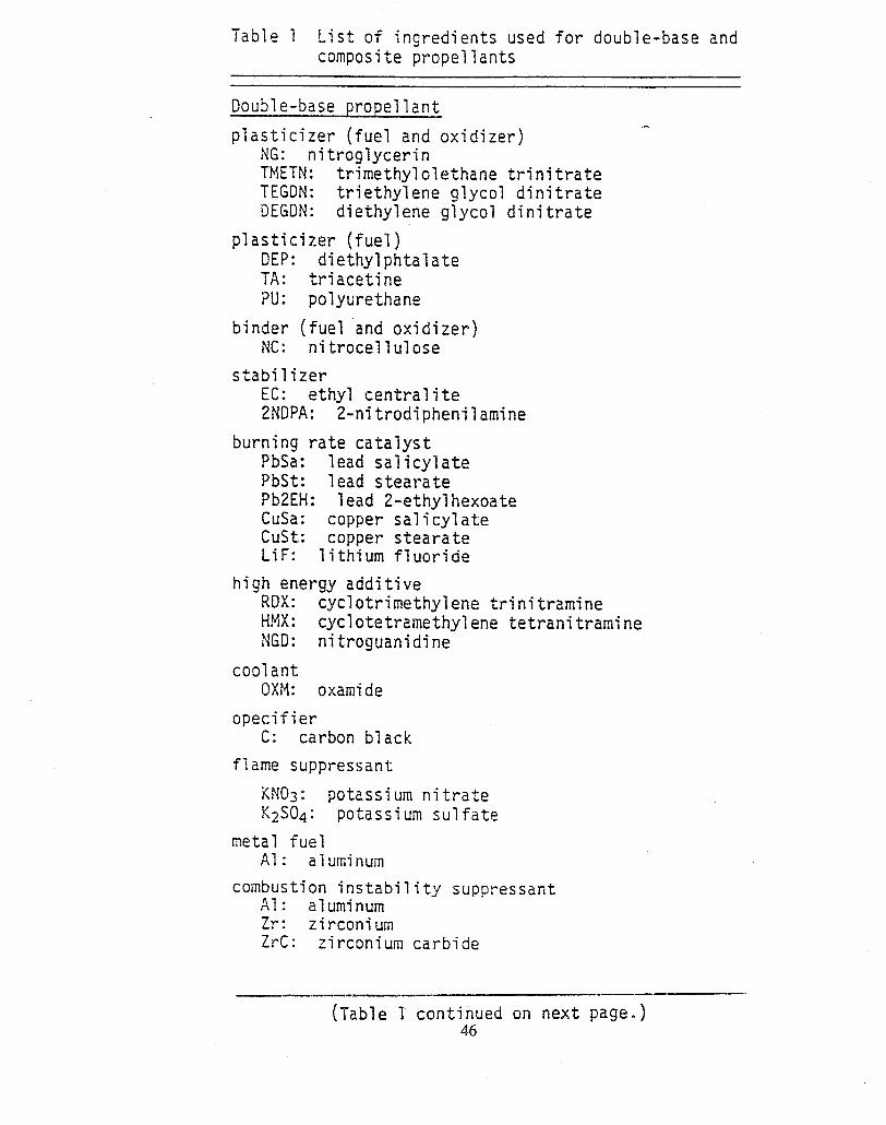
Table 1 List of ingredients used for double-base andcomposite pr-opellants
Double-base propellant
plasticizer (fuel and oxidizer),-
NG: nitroglycerinTFIETN: trimethylolethane ~rinitrateTEGDN: triethylene glycol dinitrateDEGDN: diethylene glycol dinitrate
plasticizer (fuel)DEP: diethylphtalateTA: triacetinew: polyurethane
binder (fuel ‘and oxidizer)NC: nitrocellulose
stabilizerEC: ethyl centrality2NDPA: 2-nitrodiphenilamine
burning rate catalystPbSa: lead salicylatePbSt: lead stearatePb2EH: lead 2-ethylhexoateCuSa: copper salicylateCust: copper stearateLiF: lithium fluoride
high energy additiveRDX: cyclotrimethylene trinitramineHMX: cyclotetramethyl ene tetranitramine!!GD: ni~roguanjd-ine
cool antOXM: oxami de
opecifierc: carbon black
flame suppressant
KN03: potassium nitrateKZS04: potassium sulfate
metal fuelAl : aluminum
combustion instability suppressantAl: aluminumZr: zirconiumZrC: zirconium carbide
(Table 1 continued on next page. )46

Table 1 (cont.) List of ingredients used for double-base and composite propellants
Composite propellant
oxidizer ,-
AP: anrnonium perchlorateAN: arnnonium nitrateNP: nitronium perchlorateKP: potassium perchlorateRDX: cyclotrimethylene trinitramineHMX: cyclotetramethylene tetranitramine
bi riderPs: polysulfidePvc: polyvinyl chloride
: polyurethane;!PB: carboxyl terminated polybutadieneHTPB: hydroxyl terminated polybutadiene
curing and/or crosslinking agentsPQD: paraquinone dioximeTDI: toluene-2,4-di isocyanatebWPO: tris{l-(2-methyl) aziridinyll phosphine oxideERLA-0510: N,N,O-tri (1,2-epoxy propyl)-4-aminophenolIPDI: isophorone diisocyanate
bonding agentM4PO: tris{l-(2-methyl) aziridinyll phosphjne oxideTEA: triethanolamineMT-4: adduct of 2.0 moles MAPO,0.7 mole azipic acid,
and 0.3 mole tararic acid
plasticizerDOA: dioctyl adipateIDP: isodecyl pelargoneteDOP: dioctyl phthalate
burning rate catalystFezOS: ferric oxideFeO(OH): hydrated-ferric oxidenBF: n-butyl ferroceneDnBF: di-n-butyl ferroceneLiF: lithium fluoride
metal fuelAl: aluminumMg: magnesiumBe: berylliumB: boron
combustion instability suppressantAl: aluminumZr: zirconiumZrC: zirconium carbide
47
.
APPLICATIONS OF SOLID PROPELLANTS
SOLID PROPELLANTS HAVE BEEN USED FOR BOTH MILITARY ANE COMMERCIAL
. MILITARY APPLICATIONS
- MISSILES
- GUNS
- AIR-BREATHING PROPLJLSION SYSTEMS, ETC.
. COMMERCIAL APPLICATIONS
- ROCKETS FOR LAUNCHING EARTH SATELLITES
- RAPID FILLING OF AIR BAGS
- CONNECTION OF ELECTRICAL CABLES
- EMERGENCY AIRPLANE CREM ESCAPE SYSTEMS
- MINING
- CONSTRUCTION, ETC.

Table 1 (cont.) List of ingredients used for double-base and composite propellants
Composite propellant
oxidizer .
AP: an’rnoniumperchlorateAN: ammoniumnitrateNP: nitronium perchlorateKP: potassium perchlorateRDX: cyclotrimethylene trinitramineHMX: cyclotetramethylene tetranitramine
bi riderPs: polysulfidePvc: polyvinyl chloridePu: polyurethaneCTPB: carboxyl terminated polybutadieneHTPB : hydroxyl terminated polybutadiene
curing and/or crosslinking agentsPQD: paraquinone dioximeTDI: toluene-2,4-dii socyanate/IIAPO: tris{l-(2-methyl) aziridinyl} phosphine oxideERLA-O51O: N,N,O-tri (1,2-epoxy propyl)-4-aminophenolIPDI: isophorone diisocyanate
bonding agentMAPO: tris{l-(2-methyl) aziridinyl} phosphine oxideTEA: triethanolamineMT-4: adduct of 2.0 moles MAPO, 0.7 mole azipic acid,
and 0.3 mole tararic acid
plasticizerDOA: dioctyl adipatelDP: isodecyl pelargoneteDOP: dioctyl phthalate
burning rate catalystFe20s: ferric oxideFeO(OH): hydrated-ferric oxidenBF: n-butyl ferroceneDnBF: di-n-butyl ferroceneLiF: lithium fluoride
metal fuelAl: aluminumMg: magnesiumBe: berylliumB: boron
combustion instability suppressantAl: aluminum2)-: zirconiumZrC: zirconium carbide
47
.&
,“,”:.”:’.”:”:”,”.’.’.”.”.’.’.”.”.’.’.’M/ -:.:.:.:...............4. f Ill-.4,... ““”””w,~~.,r...$,$,....,...-,,.,.,,.,.,
‘.:$:,:.:.:.:.: ,:,:.:.:.:.:.:,:,:,:.
-[
‘9DARK. FLAME .
.. . . . . . . . . . . . . .
l“’”-.6$,,..id...,.,...@,,. $..,.,,.,..,..,.,... 0, . .,,.,,... .,, ,,, ,~,,...,.,.,..,..,...,,,.,.,,.,..$,,,.,,,,.,.., $,,.,,.,,.,.,,,,.,,,.,.,,.$,,..,,..$..,..,.,,.,.,, . . . . . . . . . . . . . . . . . . . . . . .
$., ,.,.,..,,..$,,.,, $,$,,,,,.,,,.,,,..,, ‘ZONE —,.$.....$.....$......................... ‘“ ZONE —........................................“::::;.”:::::.’:;,’.”;;,”,FIZZ ZONE.,.!.,,...................................,.,.,..,,.,....$........................,.$..,..................................,,..,.,,,,,.,.,,,...,..,.,.....$..........................~,.,,..........................................................................,~.$...,.,.,,,,.,..,.,,..,$,..,,.,.,,,.,.-,.,...............................
TdPROPELLANT ~
---’1T~
To
N02 NO, H2RON02 — N2, CO
R’CHO — co, C02 — C02, H20
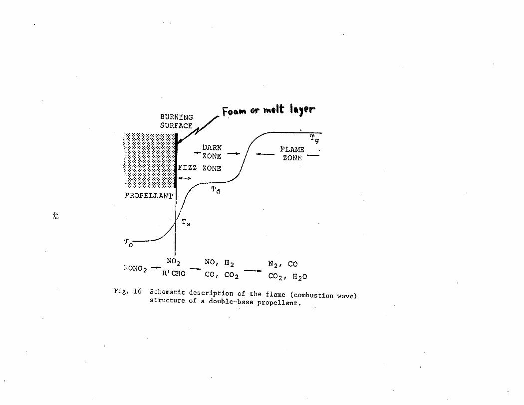
Fig. 16 Schematic description of the flame (combustion wave)structure of a double-base propellant.

Several Commonly Used Solid Explosives
HMX
Cyclotetramethylenetetranitramine
?s TATBN%
02N
oI
\ N02
H2N / Nti2
N02
Triaminotrinitrobenzene
HNAB
Hexanitroazobenzene
HNS
%N&’tiN%Hexanitrostilbene
TNTCH3
o02N / N02
I\N02
Trinitrotoluene
PETN
;H20N02
02NOCH2-C–CH20N02ICH20N02
Pentaerythritoltetranitrate
RDX
I’fo,.
H2C~N>HzI I%JJ-N\C,N-”%
Hz
Cyclotrimethylenetrlnitramine
Tetryl
H3C—N — N02
o
~N /
I
N02
\
N(I2
Trinitrophenylmethylnitramine
Picric acid
OH
o02N /
IN02
\
?462
Trlnitrophenol

APPLICATIONS OF SOLID PROPELLANTS
SOLID PROPELLANTS HAVE BEEN USED FOR BOTH MILITARYANE COMMERCIAL PURPOSES.
. MILITARY APPLICATIONS
- MISSILES
- GUNS
- AIR-BREATHING PROPULSION SYSTEMS, ETC.
. COMMERCIAL APPLICATIONS
ROCKETS FOR LAUNCHING EARTH SATELLITES
RAPID FILLING OF AIR BAGS
CONNECTION OF ELECTRICAL CABLES
EMERGENCY AIRPLANE CREW ESCAPE SYSTEMS
MINING
CONSTRUCTION, ETC.
50

\u-1NN
>+
I
I
-—
——
-=
-——
-=
II[
.—
—
1-:
a——
x;
z0t-
r~--=y,
zzaw
.
0a
1-
.
,iBaIA
lt--
C)c
<I-Lga
zwIL
L5
d..
51I

‘-Y
4n?H131TEDREGION
(a) Segmented-rocketIJXX.QrcorEiguxati~n.
(b)
Fig.
4
smzwFIcm?TEX3SZV’EBURNING -
uzH+-1 Pm
~ QUASI-sFxaDYFLOW
b/-’-z_3rd
2nd
1st
SEGMENT
SEGMENT
SEGMENT
SEGMENT
IGNITED
IG27K7ED
IGNITED
IGNIT’E’E”
‘rEfE
Significant ‘igniticm inte=vals.
2.5. Type of Segmented Rocket Mater and Time Intervals During Ignition
Transient
52

co.-.-(l)sg
a)73s
1-.-SZ
#
E
.(/3>
wsasn
(n.—g
t-nxalc.-SL
ss0.0
mt=nu)
c0●-c0.-%s
.-%Lco
m(nL
c0●—.—C
#
=a)n
aEJg
1-nnn
1-1
LI
11
CJ
u)1-
53

Propellant Studies h HighPennsylvania
State Pressure Chamber Using FT=IRUniversi&
High PressurCombustionbbomto~
17F5im I I Soieniod
ToReservior
LA-P
1 I II\
I Transmission/Absorption
Thermocouple
~ Bead I
PWchrome II Beam
: ‘\b f \
DCPower Supply
I i for ignition
Jl!.J) 1
A ua or
Ampiifier

JA.2 Strand Burning Rates
10.0
1.0
nl
o•1
PSU Data for Ti = 25°C
PSU Data for Ti = 60 “CE
‘b= ()[email protected]/
‘N
‘b= ().455* P0.58
tJ. J.
0.1 1.0 10.0
Pressure, MPa

‘i
.,
~PLICMLE EQUATIONSl-!
A one-dimensional steady-state energy balance equation
can be written:
d dT ciT~(k~)-flp-~”cc~+~p”qsub=o (1)
Iflhe thmmal propertiesenergy balance eq~a~icm
are assumed to be constant, thecan be inte~ated with the
following bounclary conditions:
x=O T=TSx =—m T=TO
to yield the following equation.:,,
T–TOTS–TO= f=xp(%”fi”ccexk )
(2)
(3)
where -m < xs O.
56

EQUATIONS (cent)
The definition of the thermal difisivity of the propellant:
ap
can be used to determineconstant.
Definition of the thermal
k—-pp.c~
k, if Cc is assumed to be
wave depth:
ap T–TO=—— ,% ‘(TS - TO)
(4)
(5)
&his usually defined to be where the temperature ratio kequal to 0.01. Therefore, the equation for the themalwave depth:
The definition of the characteristic time of the propellant:
apr=— 2rb
57
(7)

.
EQUATIONS (cent)1-
The sensitivityof JA2 propellant to changes in initialtemperature can be deduced from the equation:
The pyrolysis law mayburning rate:
be expressed in the form of a mass-
when Ts becomesvalue:
large, m will a maximum
(9)
(10)
Usfig the following ratio, the burning surface temperaturecan be estimated:
~b –E.= eXp(2 . RU. T~)mb.~a
W. Robert’s Law of combustion:
(11)
(12)

t
t
L42Thermal
1-
Wave Profile
1400
1200t
800
600 I
400
200/
100psia TestTi=60“CTest number
2000L Propellant: JA2 ~
t I 1 I I 1 1 I 1 I i 1 I t I 1 I I 1I
I 1 t II
i 1 I #
Pressure i
12
Solid Propellant
/
Gas Phase Region
O t’’’’’’””—
I ! t I 1 ! 1 I t I ! t 1 1 I ! t I ! I
-3000-2000-1000 0 1000 2000 3000
Distance from Burning Suri3ace, ~m

JA2Thermal Wave Profile2000
1800
1600
1400
1200
1000
800
600
400
200
0
Propellant: J/U!100 psia Test Pressure \Ti = 60 “CTest number 13
1 i I I I I I i i I I 1 I 1 I 1 I t 1 I 1 I t 1 I I 1 I I
! ! ! ! I ! 1 I I I I 1 ! I I ! I 1 I I t 1 I I I I ! t I
Solid Phase Region
-3000 ‘-2000 -Joo(-) ()
Distance from Burning
1000
Surface,
2000 3000
~m

(a) particles in surface liquid layer at0.65 MPa (80 psig)
Fig.
2.
3.
(b) attached flames tocarbonaceouspatches at 0.51 MPa(60psig)
(c) multipleattached flamesat 2.23(310 psig)
Ml]a
Blwning surface of RDX samples of0,25 in. diameter
.:
*
‘4&),;:
.’+)-,,,,J. ,y
;;..,.
(b) flame attached toagglomeratesat (c) marlypoints ofattachmentat Z.{61.23 MPa (165 psig) MPa (300 psig)
Burning surface of M43 samples of 0.25 in. diameter

.-
62
.s’
In
ti
QL.Q
-)u
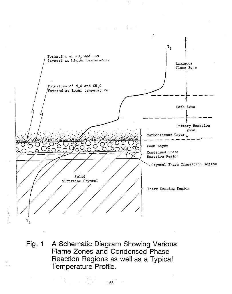
Formation of N02 and HCNfavored at higher temperature
/ /
favored at low~r
.,..
Formation of N.O
‘f
8 ITi
LuminousFlame Zone
and CH20
temperature——— —
—.— ——
-.””. . . . . “.”. “.”
-.
k-- . —— ——
Dark Zone
L——————t
primary ReactionZone
Layer ~CarbonaceousI-.—. -—— ——— — .——
Foam Layer
Condensed PhaseReaction Region
\‘. Crystal Phase Transition Region
Inert Heating Region
Fig. 1 A Schematic Diagram Showing VariousFlame Zones and Condensed PhaseReaction Regions as well as a TypicalTemperature Profile.

.=i~ure1:Typical rnicrogra?ks for a) surface bubble analysis (XM39at 1 atm and 300 ‘iV/Cm~) aEd b) meltlayerthicknessdetermination(,X2139at3 aLT and 100 lV/cm2).
a
b
64

..
heatfeedback
,.
Tfoam
layer
heterogeneousreactions
pyrolysisvaporization
gas releasing
surface tension
* and bubble burst & ———— .— ——
—. ——
~=— bubb~tion‘- –n–
U f dragand interracial
specmass
c1 resolve
es o 0diffusion
resorptionof dissolvedspecies
gas-phaseinterracialheat transfer
8:s%$GL:i,::ui(!) vaporization
ooxidizer pyrolysis fuel liquefaction
heterogeneous
and sublimation and decompositionreactions
fuel pyrolysisoxidizer liquefaction
+. ~ / / / ///\-/ //
Fig. 2 A Schematic Diagram Showing the Physiochemical Processesin the Foam Laver of a Nitramine-Based Solid Prmellant.

. ..
.......
~(?~om~ositk)~ of R!))( (f-.Melius,l99o)
At Fast Heating Rates
. .
‘“a&
‘#3 (16)
.0“ ~’() #; (37)
i-,,N N:”
+ 2 H-C o
#6 (37)H\
+ C=N*\H
\#6 (31)
+ #n (A E): Position, Order, and Energy
of Chain Bond Breaking (Energy in kcahno[e)
Figure 10. Decomposition mechanism for RDX under rapid heating rates. Thenumber indicates the order in which the bonds are broken. The bond breaking energies(in kcaI-mol-~) are given in parentheses The final products are HCN, N(I2, and EL
(~)“f* “’I-r”
I I
-CHwNJXLYPbCHv
-CHZN-H
Q= ,OHf’J
-CH2-N
tlH*O
OH
1+ H20
q .$3 (:)?H N
+ CH2-lh3&
ttH20
00“r
ICH20 + H-kCH2-1
;(~)
Figure 11. The water-catalyzeddecompositionpathwayfor nitratines containingthe-(-CHZN(NC)Z)-)-subgroup. The inidal step is the hydrolysisof the C-N bond in(~) to formthe primarynitram.ine(~) and tie hydroxymetiylspecies(~). T1-icprimarynitrarnine undergoes further decomposition to form NzO and the hydroxymethylspecies Q), which undergoes further decomposition to form CH20 and the primary
nimamine (2)
66

11111~
IllII
II
fI
1
---k!fH—
67
m-0g-0sm
.,

I
Desirable Features of Energetic Materials-1
❑ Deliver high specific impulse and high impetus
~ Generate low molecular weight combustion product gases
❑ Being environmental compatible- Reduced emission levels of NOX,SOX,CO and otheraw undesirable gases- Reduced particulate
❑ Have long term storage capability
❑ Possess low vulnerability characteristic-=Thermally stable- Reduced ESD hazards- Reduced impact sensitivity

Desirable Features of Energetic Materials (cent’d)
■ High Reproducibility in Burning Characteristics
■ Good Mechanical Properties
- High dewetting stressmm - High fracture toughness
- Low glass transition temperature
■ Easy for Processing and Manufacturing
■ Low Cost

Scientific Challenges in Combustion ofSolid Propellant (SP)
“ Extremely thin reaction zones [4(1OO pm)]
* Regrtission rate depends upon the rate of heat release in the thinsurface reaction zone and the heat feedback from adjacent gaseousflame(s),
4*o Surface reaction zone can not be characterized easily due to the
complicated condensed phase structure:— Foam layer with numerous physical and chemical processes— Heterogeneous surface conditions— Deposition and expulsion of carbonaceous residues— Intermittent flame attachment to burning surface— Uncertainty in nucleation rate and initial bubble size distribution ‘
“ Liquefaction process at the liquid/solid interface is a strong function ofpropellant formulation.
* Thermal and transport properties of propellant ingredients and theirintermediate products are diffmdt to characterize.

Scientific Challenges in Combustion ofSolid Propellant (SP) (cent’d)
Transient burning rate (rb) of SP could differ si nificantly from steady-state rb. Usually the parameters (e”g“? ~P>ilTJi#iJp) required todetermine the transient rb are not easily obtainable.
Harsh environments for combustion diagnostics— High temperature and pressure— Multi-phase behavior of the reaction zone— Condensed phase decomposition and reaction
Multiple reaction pathways
Multiple ignition mechanisms (laser induced, conductive, shock waveinduced, ESD, impact, friction, etc)
Go/No Go ignition boundary of SP can vary significantly with theoperating condition (suchas degree of confinement).
Complicated interactions between mechanical deformation andcombustion processes

.so
u)
?2-6E.-;3
CzCL
5?3u)a)
g2!
-gmcosE!
m1?
‘xC
ta)
><
-nnQ
u)
mco
mF5.-
Q)
“E8co
0g8-
mu.—gs8’
c% usa
sc1)“aof
-gas
%.-fa0)E
’<t.)
mea)L
za)K
>n-1!%a)5)a)
L(Y
),
$?■72
II
I
tY
I

Suggested Approach for State-Of-The-Art AdvancementsI
■ Utilization of Advanced Diagnostic Techniques for DetailedMeasurements
❑ Application of High-Speed Computational Facility for Simulationof Various Combustion Processes
,3 Encouragement of Interdisciplinary Approach and StrongInteractions Between Constituent Disciplines, Including:
- ChemistryPhysicsThermodynamicsFluid MechanicsHeat and Mass Transfer -
Turbulence
Material SciencesInstrumentationMathematicsNumerical MethodsMechanical Design
Ballistics

L
Necessary Elements for Progress
No Advancements Can Be Achieved Without
* Research Funding $ ??4-P.
“ Long-Term Strategic Planning and Programs
“ Continued Support of Specialized Personnel inthis Area
● Cultivation of New Generation of Engineers andScientists with Continued Stimulation

NAVAL AVIATION SYSTEMS
‘r=w] Solid Propellant Gas Generator WorkshopNational Institute of Standards and Technology Ak4
June 1995NWALAIU WARFARE CENTER
gza?m~g~w%vskiyw~$:>y*<>~~$:<:$flk&:s>\>.A&A.:.:<.......:.+:.<.... . . . .. ........ . .. . . . .. .. .. , . . +..> v . %,\.y\.:+ . . . ..q?..\.>x..y\3>*Y*.k\\\\\\\<\\\\\\\\\\\\\\\\\%M\\mm
Fire Extinguishing Pyrotechnics
Jim Hoover, Russ ReedCombustion/Detonation Research Section
Vicki Brady, John HitnerAirframe, Ordnance and Propulsion Division
Leo Budd, Mike Gray, Marty Krammer, Hardy TysonWeapons Survivability Laboratory
Naval Air Warfare Center Weapons DivisionChina Lake
Unclassified

NAVAL AVIATION SYSTEMS
‘rzku~j Goal and Objective A*/NAVALAKI WAIIFARE CENIER
I
Goal from the FJext Generation l?lan (NGl?):
Objective for China Lake Gas Generator Efforts:
NAVAL AVIATION SYSTEMS
‘~%:~jlj] Fire Science &Technology Panel .FY95 Participants A
dUAVALAIWARFARE CEtilEU
~.::::::fw~:::~.::f<:::::::*.::~~<::::>.y,t:!::::::::::.:.....:...:.:..i.:.:.:.:.:.:.:.:.,.....>:<... .,,,. . . . . . . .. . . . . . . . . . . . . . . . .\,\\\\\\\\\\\\\\\,\\\~.~~~\\~\.~~~~~\~
44
Joe Benavides, NAWCWPNS AlbuquerqueProf. Matt Kelleher, Naval Postgraduate SchoolLeo Budd and Hardy TysonWayne Doucette and Gill CornellDr. Warren Jaul, Brenda Allen andVicki Brady
Rodney Harris
Dr. Kelvin Higa, Dr. Rich Hollins and Dr. Curt JohnsonThorn BoggsDr. Jim Hoover and Dr. Russ ReedLes Bowman and Dr. M.J. LeeDr. Jo Covino, Dr. Ilzoo LeeJay McClellanRoss Davidson, Dick Rivers
and Ross Heimdahl
and Wil Simoneau
A28N103Me/KK418300D473AOOD47311OD47341OD474220D474300D47431OD474320D474330D528400D824220D

NAVAL AVIATION SYSTEMS .
‘J’<l\J~l Fire Science &Technology PanelFY95 Accomplishments
@ Coordinated local review of DDR&E proposal ckafts “Next Generation l?ireSuppression Technology’y ($48M/8 years)
@ Conducted China Lake Fire S&T Workshop ancl established working groupto promote Fire S&T work within NAWCWI?NS
* Sponsored Fire S&T marketing brochure and electronic media describing2China Lake RDT&F#capabilities and expertise
+-?+Conducted Navy-wide Fire S&T Workshop (14 &15Mar95atNASNI)attendedby NAVAIR,NAVSEA,ONR,NRL,NAWCAD (Lakehurst andWarminster), NAWCWI?NS, NPG and Federal Fire Dept..
~~ Obtained NAVSEA sponsorship for Shipboard Magazine Fire ProtectionProgram ($2.5M over 5 years) and.JTCG sponsorship for Pyrotechnic FireExtinguisher R&D.
+ Developed networked teams (Industrial/Academic/Gov’t labs) for pursuingmajor outside sponsorship (i.e., SERDP) and in-house discretionary projects
+!+Participated in international Fire S&T meeting and NIST Workshop

NAVAL AVIATION SYSTEMS
‘r=ud]Gas Generator Formulation
A
*Work History at China Lake
INAVALAFI WARFARE CEtilEU
1979 High Nitrogen Binder (GAJ?) Work (Funded by ARC)Goal: No Ammonium Nitrate (AN)Significance: High nitrogen binders attractive for gas generators
1980s High Nitrogen Binder Work (Funded by ONR/ONT)s Collaboration with Thiokol (Dr. Manser), later with Aerojet
Goal: Alternative high nitrogen compounds - no ANApproach: demonstrate azidooxetanes as good as PEG E-4500 (Dow),tetrazoles and GAP
1979-1982 NAVAIR Gas Generator TechnologyAmoco MK-6 (N-28 comp.), AN/l?E binder, 2000-2200”F, 0.06”/sGoal: 1500”F, 1“/s, noncorrosive, no particulateApproach: High nitrogen cmmpoumls Yield less H2Q CO, C02; newdeflagration mechanism for azides and tetrazoles, driving force is high ~

NAVAL AVIATION SYSTEMS
‘Jz2u!!jGas Generator Formulation
AA
Work History at China Lake )NAVALAR WARFARE CENTER
1983=1985 NAVSEA Submarine Deballasting Gas GeneratorsGoal: High Nz (inert), noncondensable gases, tailorable sustained higher burnrate than AN (>0.5’’/s)Approach: High nitrogen compounds with high nitrogen binders
~ (i.e., hydroxyethyltetrazoles)
1987 l?atent on I?yrotechnic Fire Extinguisher (l?FE) Compositions
1992 Flame Suppressing Gas Generator (FSGG)
J

8
g.+dbcd

NAVAL AVIATION SYSTEMS
“.rE2-’uil FSGG-02 Propellant Conceptand Calculated Burn Rate
@~$w$z?@z@m&3%msxs%2\%x\mTs$-\m~~,:.:.x .....y.. ... .................. ........<....,........... . ... .. .. . .. . . . . ,,,,.,,,,,.,.,,,.. . . . .. . . . \. ,. . .,.,.,.,.,.,..,. . . .. ......... . .,!,,...Y,,,,..
..,
\ \\h\NYK<w>hYhN\\\%\\\\\\NNRNhN>mwN%\N\%N%. . . . . . . . . . . . . ..... . . . . . . . . . . . . . . . . . . .. . .... . . . . .. .. ..... . . ... . . . . . .. ..... .. . . . . .. . . . .. ... . ... .. .,.\
Initial Concept
1.5Lb~propellant
Density:0.0542 Lb~/in.3
CStar: 4000 ft./s
Burning Rate:0.50 in. /s @ 1000 psia
Hope: 0.50

NAVAL AVIATION SYSTEMS
‘JZ;WJGas Generator T&E History
at China Lake A*1
NWALAUl WARFARE CENTER
W&is’..,.v...+:.<..: *,* . .&.\k<, <***x.whwT~~...~~msm’’>xw%> \, -,..,.. .. .. .. ... .. .... .. iYT\y\ywwm \-................................... . ............. . ..... .,,...~~~~~~~~~~:t-:c:............x......................>..........,%.>.......?.3...Aktib>x%\?yy*i*)mwk~y~\\~~~~~~
Weapons Survivability Laboratory Facilities
Test Equipment / Instrumentation / Ballistic ThreatsTest Sites / Fabrication Capabilities
00b.)
High Velocity ;irflow System (HIVAS)Airflow Source:Bypass airflow ductedfrom 4 TF-33 Pll engines
Velocity Ranges:160-550 knots over 18 ft.2100-300 knots over 35 ft?40-120 knots over 110 ft.2
Rotatability: 360° to cover6 test pads

.
NAVAL AVIATION SYSTEMS
‘rE4dklGas Generator T&E History
at China Lake
Testing Program:F/A-18 Dry Bay Simulator
Dates: April - June 1993
ld?rogramSponsor(s):Navy,
Techn:North]
b7A-18
cal Support:‘Op,
McDonnelOlin
-Douglas,
Significance:First demonstration of gasgenerator (Olin) effectivenessin real-scale scenario sire.
Test Conditions:Real-scale F/A-18 dry bay simulator with fuel celland clutter, HIVAS 450-500 knots,FIalon 1301 and FM-ZOObaselines,Ballistic ignition (small arms, 12.7-30 mm),Olin gas generator hardware

NAVAL AVIATION SYSTEMS
“rwm A*tNAVALAlfl WARFARE CENTER
g$gg.~m;~” w$~fn~ ~~wwk&\*% <+%> Six&\:& b\. . . . ......... ..... ..... ..... .................... ........ ...... . .. ...... . ......... . . . .. .. . . ... . . ,\..,..:.>..:v.:.y+.\\y3\\\\\\\\:\\\\\\\\\.*%\~~~w~%\\. .. ................... ................................................. ......... .............. .......... ...... .. . . ..... . ... .......\. \.. .
Gas Generator T&E Historyat China Lake
Testing Program:V-22 Wing Dry BaySimulator
Dates: Dec. - Jan. 1994wMProgram Sponsor(s):Navy, V-22 (CDR Curtis)
Technical Support:Bell-Boeing, Olin
Significance:Active suppression neededand demonstration of gasgenerator (Olin) effectivenessin real-scale simul. scenario
Test Conditions:Real-scale V-22 wing dry bay simulators (3) withfuel cell and clutter, HIVAS 250 knots,Halon 1301 and FM-200 (RFE) baselines,Ballistic ignition, Olin gas generator hardware

NAVAL AVIATION SYSTEMS
-JTJ’’lyl Gas Generator T&E Historyat China Lake
<.>s.:*:.*k*w:y<>*\.\>m>\\\\:.\y %; .y$~~*t&su*2Y&(*ti>,:wb>YQN\k%.ki\<hkkhshLxti,N\R\yww\~V.................... . . . . . . . . . . . . . :.. ,, . . . . . . . . . . . . . .. .. .. . . . . . . . . . . . . . . . . . . . . . . . .. . . . . . . . . . . . . . . . . . . . .. ............ .,. ,,.\..., .. .. ...... ,,.7, . .. .. . . . ,,, ..‘“‘‘“‘““““‘“”””’’””””””””“ .“”’.’”.”-”.”’.”.’.’,”’..’” ‘~.””,.`"`.Y.:.v>'"'.'...........~Y.............\Yh\F.\\.>\\\<\\\\\&N\\\\m\\N\\\\%~\%\\\\~
Testing Program:l?/A-18 Engine NacelleSimulator
Dates: Aug. - Nov. 1994
!%ogram Sponsor(s):Navy, F/A-18NAVAIR (Mr. Homan)
Technical Support:Northrop, McDonnell-Douglas, Olin
Significance:Demonstration of’gasgenerin rea
ltor (Olin) effectiveness-scale scenario sire.
Test Conditions:Real-scale F/A-18 engine nacelle simulator withclutter and air flow, Halon 1301 baseline, sparkignition and ballistic ignition wrap-up, Olin gasgenerator hardware (manifolded, unfiltered)

..
NAVAL AVIATION SYSTEMS
‘JRu!.lj
Future Gas Generator T&E A*at China Lake dNAVALAKI WARFARE CENTER
t%k3+... .......~<w<.*.&~b~v&&&B&~~~~~. .hRwf.fw.+>:t$h:*y ?.. y?~~ .,.>,... .. . ... .. .. . .... ... .,%+,..,... . . . . . . . . . . .:..,,,.:::::,:: .:. . . . . . . ... ... . .. . ,.& .... . . . =.$.. . \w\:;xi\\Ak\N\\\\NNk\\\\R\\\%\%\~““ “.”-”-’”-”. ‘.-”.”. .“-’’.’- . . ..- +’...~---. J.. . . . . . . . . ..... ..... ...%. ....%. .+ \. . . . . . . . . . . . . . . . . . . . . . . . . . . . . . . . . . . . . . . . . . . . . . . . . .. . . . . .. .. .. .. .. .. . . . . . . .. .. . .. . . .. .
+ F/A-18 E/F Fuselage Dry Bay Fire Suppression Test, FY95Sponsor: Navy (CPT Dyer)Tech. Support: Northrop, McDonnell-Douglas, Olin+~~Real-scale E/F modified C/D”model aircraft+* Proof of concept for gas generators with ballistic ignition
004 ‘s Airflow (HIVAS) 450-500 knots
+ V-22 Midwing Gearbox Fire Suppression Test, FY96Sponsor: Navy (CDR Curtis)Tech. Support: Bell-Boeing, Olin~$Real-scale V-22 structure~sProof of concept for gas generators+ Airflow (HIVAS) 250 knots
+ AV-8B Dry Bay and Aft Wheelwell Fire Suppression Test

.
NAVAL AVIATION SYSTEMS
“G2$m] Fire Protection RDT&E“A
*Future Efforts
dNAVALAIU WARFARE CENTER
$~~Jj?*.~$\m>yt.tw>.:. R>\*lml>\\\\\...\m\ ‘ m\-\-B\m\~*>.,..*h.,\&.Y. . . . . . .. ,...\T\Y\&*>&%\\\\k\*\\\>\>.. \.... .. ... .. . .. . . ..* . ....+*... ..
. . . . . . . . . . ... . . ......... . ...y .... ....<...%.Y.\Y.>y\\&\\\\\\\\\\\\Yhy~c$&\\\\\\\\\\\\\\\\\\\\\\%\\%\%\\%\;::::::::::::~$,~~::: ::~:!:::::::.j$f$..:j >k .:.:.:.:.:,:+:...,.>,{,,..,..\ ....... ........... ,.,. . . .. .. \
Continue Support of NAVAIR and NAVSEA Programs through:
+ Weapons Survivability Laboratory+ Fire Research Office (Les Bowman)
~ + Fire S&T Networks Panel (multi-competency)m
Continue Team Building Efforts through S&T Networks to address:
DDR&E’s Next Generation Plan BAA (SERDP type proposal)Market ILIR discretionary support for “Superagents” researchMarket support for scale-up and loading of FSGG formulationsUnclassified/unlimited dist. information services via Int.ernet (WWW, etc.)
Rapid, Low-cost, Total Quality Response to DoD Needs

Modeling and ExperimentalValidation of
Pyrotechnic Gas Generators
HermanThe University of Illinois at Urbana-Champaign
Urbana, Illinois
and
P. Barry ButlerThe University of Iowa
Iowa City, Iowa
89

REFERENCES
Butler, P.B., Krier, FLK., Faigle, E.M., Sernchema, J. I-l., and Thompson,R., “Modeling Azide-Based Propellant Combustion in aPassenger-Side Automotive Airbag Inflator,” The CombustionInstitute Central States Meeting, April 26, 1992, Columbus, OH.
Butler, P.B.,CombustionCO#r-ss of
.
Butler, P. B.,SimulationAutomotiveScience, Vol.
Butler, P. B.,
Kang, J., and Krier, 1-1.,“Modeling Pyrotechnicin an Automotive Airbag Inflator,” 5th Internationalthe Groupe de Travail de Pyrotechnic, June, 1993,
Kang, J., and Krier, H., “Modeling and Numericalof the Internal Thermochemistry of an
Airbag Inflator,” Progress in Energy and Combustion19, 1993, pp. 365-382.
Kanq, J., and Krier, H., “Numerical Simulation of aPre-Pressurized- Pyrotechnic ~ut~motive Airbag Infiator,” 5thInternational Congress of the Groupe de Travail de Pyrotechnic,June, 1993, France.
Berger, J. M., and Butler, P. B., “Equilibrium Analysis of of ThreeClasses of Automotive Airbag Inflator Propel lants, ”~;4mbustion Science and Technology, Vol. 104, No. 1-3, 1995, pp. 93-
Greenlee, C. L., and Butler, P. B., “Influence of Product Speciesselection on Thermochemical Equilibrium Calculations,part 1: Energetic Materials,” submitted to Propellants, Explosives,and Pyrotechnics, 1995.
90

BACKGROUND
CONSULTANTS TO AIRBAG INDUSTRY
MODELING WORK
m developed general-purpose gasgenerator models
- validated performance of numerousinf Iators
. used in design of new inflators
EXPERIMENTAL WORK
. cold-flow test apparatus
. combustion test apparatus9 ignition test apparatusm design of experiments (DOE)
ADVANCED CONCEPTS
. next-generation inflator designs
91

AIRBAG COMPONENTS
~ CRASH SENSORS AND COMPUTER LOGIC
● BAG HOLDER AND EXTERIOR PADDING
e NYLON AIRBAG ASSEMBLY
92

ENGINEERING CHALLENGES
●
●
●
●
●
●
●
IGNITOR RELIABILITY (output history, is itrepeatable ?)
TIMING OF EVENTS (pressure-time profiles)
PRODUCT CHEMICAL COMPOSITION- tank gasm tank particulate. inflator slag (multi-phase mixture)
AMBlENT OPERATING ENVIRONMENTm temperaturem pressure
AIRBAG DEPLOYMENT. dynamics of bag filling9 thermal and mechanical response of bag
as it opens
PROPELLANT LIFE (>15 years)
PROPELLANT DISPOSAL
93

GOALS AND OBJECTIVES
e DEVELOP A MODEL THAT DESCRIBES THETHERMOCHEMICAL EVENTS OCCURRING[N A GAS GENERATOR
o VALIDATE MODEL WITH EXPERIMENTS
e STUDY THE INFLUENCE OF MATERIALIPROPERTIES AND DESIGN PARAMETERSON PERFORMANCE OF GAS GENERATOR
m maximum inflator pressure, temperature. maximum tank pressure, temperature. tank impulse. pressure-time profiles. temperature-time profiles. tank gas composition
@ COMPUTER PROGRAfVI FOR DESIGN OFNEW GAS GENERATORS

PHYSICAL MODELOF
GAS GENERATOR AND DISCHARGE TANK
ScreenIgni. to
RuptureFilm #1
RuDture
DISCHARGETANK

GAS-ASSISTED PYRO’TECHN—. . — C INFLATOR
Rupture Filter
10
1
0.1
Chamber Film
DischargeTank
\.-Body Exit~ Nozzles
A
bursti/
/

GAS GENERATORPERFORMANCE PARAMETERS
time, 1 Max, P
mout
TIME
T
TIME
T

COMPUTER SIMULATION
e KEY FEATURES INCLUDED IN MODEL
= ignhion time delay (flame spreading)D tracks individual species with time (g, s, 1). grain geometry (form function)m nozzle discharge flow rates= filter collection process and gas flow
restriction
o MODEL PREDICTING
m heat exchange rates. hardware temperatures. propellant properties per timem flow properties at exit nozzle
* EXPERIMENTAL VALIDATION DATA
m ignition delay time9 mass of collected particles in filter. pJ(t), TJ(t), xJJ(t =-+, pJJ(t = -)
* NUMERICAL PROCEDURE
m iarge system of ODE’S (ciT@t, cimk/dt, etc.)m solved using DVODE. CPU time is 0.1 = 1 minute on HP-735
98

MODEL DESCRIPTION
● BASED ON FUNDAMANTAL CONSERVATIONLAWS (MASS, ENERGY)
MAJOR SUBSYSTEMS CONSIDERED:
gas generator assemblydischarge tank
GENERATOR ASSEMBLY INCLUDES:
body (metal hardware)propellant grainsigniter assemblyfilter screenthin metal foil for environmental seal andburst strength
Q DISCHARGE TANK INCLUDES:
9 tank walls (heat loss)9 mass discharged from inflator
● DIFFERENT MODES OF HEAT TRANSFERARE CONSIDERED
99

MODEL ASSUMPTIONS
e
FILTER
FILTER
DOES NOT COLLECT GAS SPECIES
DOES COLLECT SOLID ANDPRODUCTS OF COMBUSTION
GAS
collection efficiency depends ondesign (mass, fiber size, etc.)
MIXTURE IS:
multiple speciesCP(T)well-mixed, perfect gascan be chemically reactive
CONDENSED SPECIES ARE:
multiple speciesCP(T)not compressible
LIQUID
filter
100

IllnoE-1a
Lo
xz41-Wnnz01-aKwzu)
aC9
“E4101

INFLATOR MODEL FLOW CHART
f Cornbustlon Chamber 1 .,.,.,.,.,.,..,............ ...... ..................................... ........ ........ .........+...... .......................... ........... .. ..... ... ,.,............................ ........................ ................ ................................ .... . ....................J=l .......x...:::.,:::x>Ax:.:vx<vi<.*.:.:,N:.:.:t<.>>+..,...AY.:+:.>:.x.:.:.:.>
IE
/ *
f
I Plenum Area I A
102
—

I ..;.,,, I
THERMODYNAMIC< DATA BASE
●
●
●
●
Treats multiple chemical species in propellantgrains and products of reaction
Gaseous as weIl as condensed-phase speciesare possible
Uses NASA/CHEMKIN thermodynamic database for C&(T)
C;k(l)alk+a2kT+ . . . + aNk~
(N-1)
R=
C~k(T) used to assemble enthalpy H:(T)
— —.
—. —
T(K)103
2s00

-r(y)
104

GAS-PHASE CHEMISTRY
<<<<<<< GAS-PHASE REACTIONS >>>>>>>
Rxn number Symbolic representation----- _____ _____ _____ ________ _____ ----- _____ ----- _____ _____ ----- ----- _
1.2.3.4.5.6.7.8.9.
10.11.12.13.14.15.16.
C+02<=>CO+0C+OH<=>CO+HHCO+OH<=>H20+C0HCO+M<=>H+CO+MHCO+H<=>CO+H2HCO+O<=>CO+OHHCO+O<=>C02+HHCO+02<=>H02+C0CO+O+M<=>C02+MCO+OH<=>C02+HCO+02<=>C02+0H02+CO<=>C02+OHH2+02<=>20H0+OH<=>02+H0+H2<=>OH+HH+02+M<=>H02+M
105

—
C=MKm-11: FLOW CHART
0- /’dyna~c
.
“3r%$’
gEi z
lx* \Yi&Ikii \
\Interpreter\ 4
Chen&in-11 * a13inary Linking 4 Printed
I?ile Output and
IDiagnostics‘v<
A
[
Thermodynamic PropertiaMolar Production RatesSpecific HeatsState Variables
106
—
I
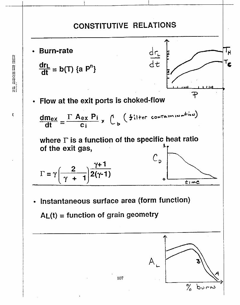
. ..—
CONSTITUTIVE RELATIONS
‘r● Burn-rate
● Flow
dme~dt
b(T) {a P“}
whereof the
at the exit ports is
r Aex Pi %Ci
c b
r isexit
2
dr’
Ck L-“//--[ I I I u ii 1 1 ) 114
choked-flowT
a function of the specific heat ratiogas,
, y+l
[Jr= Y- ‘y +3 ‘(Y-l)
● Instantaneous surface area (form function)
AL(t) = function of grain geometry
‘r

I !
~.,.:.:?.-,3,.+;.,. ..... 2 .. . >. :
PARTICLE FILTER
..—.
e FILTER FLOW LOSS
LTER COLLECTION
mC,l,out
mc~=rn ,
g,l,mt -
H=FIC ENCY
‘Ug,lJ?
4
I
108
Ili-lg
DL dowlLs&ti
l-hc .OIH

RESULTS - COMPUTER SIMULATION
2500
2000
15CQ
1000
500
0
Combustion Chamber
I 1 1 I I I 1
0 25 50 75 100 125 150 175 :
Time [ins]
70
60
50
40
30
20
10
0)
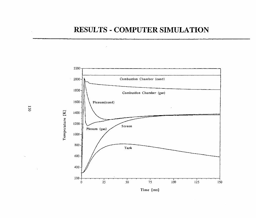
RESULTS - COMPUTER SIMULATION
220(
20QC
1800
600
400
8(KJ
600
400
200
Combustion Chamber (cond)
Combustion Chamber (gas)
\
Plenum(cond)
Plenum (gas)
o 25 75 100 125 150

c)I
0wo—
ov
o_
suo!goeJAssew
sa!~ads
80

g“uo$J
4
—
112

RESULTS - SENSITIVITY STUDY
1.30
1.00
0.90
mp
a
1“ 1.05 1.1 1.15 1.2
113

IRESULTS - SENSITIVITY STUDY
ii!z“
1.60
1.40
1.20I
n
1.00
0.801 1.05 1.1 1.15 1.2
114

NECESSARY FOR MEANINGFUL INFLATORSIMULATION PROGRAM
●
●
●
●
●
●
●
●
●
●
●
●
DESCRIPTION OF PROPELLANT AND PRODUCTSCHEMICAL COMPOSITION
~EMpERATURE=DEPENDENT SPECIFIC HEATFUNCTIONS FOR ALL POSSIBLE SPECIES
PRECISE SOLID PHASE PROPERTiES (V, DENSITY)
SURFACE REGRESSION RATE ( = F(P,T) )
SURFACE/VOLUMERATIOOF PROPELLANTDURINGBURN
IGNITION SEQUENCE OF THE PROPELLANT(COATING, SQUIB SIZE, TEMPERATURE, ETC.)
FRACTURE OF GRAINS DURING RAPIDPRESSURIZATION
SOLID-PHASE THERMAL PROPERTIES (MODEL SLAGFORMATION)
NOZZLE OPENING PROCESS (INCLUDED MULTIPLENOZZLE SIZES TO AVOID SADDLING EFFECT)
HEAT LOSS TO SCREENS
DYNAMIC MASS-FLOW DISCHARGE COEFFICIENTS
12EvEL0pMENT OF ExPERIMENTAL PLAN IN pARALLELWITH MODEL DEVELOPMENT
115

EXPERIMENTAL REQUIREMENTS
. DESCRIPTION OF PROPELLANT
9 chemical composition9 grain geometry- burn-rate function
e ANALYSIS W’ SPECIES REMAINING IN THEINFLATOR AFTER FIRING
~ IDYNAMIC PRESSURE MEASUREMENTS IN:
m inflator bodyw discharge tank
* AFTER-FIRING INSPECTION OFHARDWARE FOR CONDENSED PARTICLES
o INDEPENDENT STUDIES OF THE FILTERCOLLECTION EFFICIENCY
. INDEPENDENT STUDIES OF THEPROPELLANT IGNITION SEQUENCE
116

PROPELLANT CONCERNS
●
●
●
●
●
PRODUCT CHEMICAL COMPOSITION- tank gas9 tank particulate9 inflator slag (multi-phase mixture)
LIFE (>15 years)
DISPOSAL
PROPELLANT OUTPUT
D hot vs. cold firing- squib can fracture propellant grains
LABORATORY COMBUSTION STUDIESSHOULD REPLICATE ACTUAL GASGENERATOR OPERATING ENVIRONMENT
- high confinement (solids loading)9 pressure variations (14.7 -4,000 psi)9 possible slag build-upw flame spreading
117
-.

l-’(/3L
u1-
Ct)
3m
II—
118

IGNITION CONCERNS
● ACTION TIME
w hot vs. cold firing= uniform performance of “similar” squibs9 some “good” gas-generating
propellants require accelerant coatings
● IGNITOR OUTPUT
- hot vs. cold firing. uniformity in performance of “similar”
squibs. can fracture propellant grains
● IGNITOR LIFE
m uniform performance after storage
s INDEPENDENT STUDIES OF IGNITOR ANDPROPELLANT IGNITION SEQUENCE ARENECESSARY UNDER ALL OPERATINGCONDITIONS
119

f-(J)wl-”
zz(!!s
vC&
urw
.
zJl-
w--------
....
II120

CONCLUSIONS
COMPREHENSIVE GAS GENERATOR MODELWAS DEVELOPED
MODEL HAS BEEN APPLIED TO
9 conventional pyrotechnic inflators- hybrid inflators
AGREEMENT WITH DATA IS EXCELLENT
MODEL IS A USEFUL TOOL FOR DESIGN ANDDEVELOPMENT OF:
9 new inflators (material properties, size, etc.)- new pyrotechnic compositionsm propellant grain modifications9 ignitersw new filter designs
EXPERIENCE SHOWS THAT A RELIABLEEXPERIMENTAL DATABASE IS ESSENTIAL
WE RECOMMEND THAT SOLID PROPELLANTFIRE EXTINGUISHMENT PROGRAM FOLLOWSAME METHODOLOGY
121

ALTERNATIVE IDESIGNS
Propellant
/ Cooling Filter
4. 6..%
‘A A**A‘+’AA AA
‘J#. A*A
AA AA
‘A.+. AA
I t--d A*** uu
a.) Standard Scheme
Gm.nuhtr, Propellant
I-J
b.) Self-cooling scheme
122

ASPECTS OF FLAME SUPPRESSION
Anthony Hamins
Building and Fire Research Laboratory
National Institute of Standards and Technology
Gaithersburg, Maryland 20899

Give gwklance on the performance of fire
SUpp~~Ss3io~ s~~t~m~ ~~ engine na~ell~s.
Conmare Effectiveness of 3 Kev A~ents
I?ormu.la Designation IUPAC Name
CF-J ,. iodotx.ifluoromethane
c2EIF5 HFC=-125 pentafluoroethaneC3HF7 HFC-227ea heptafluoropropane
124

1. Whattion?
. ——..— —.-. .. . ..
Testing solid Propellant Gas Generators
are key parameters controll$mg flame exti.nc-,.,
...,
Air Temperature
Pressureis“ baffle height
Agent
Fuel
Flow Velocity
I
2. What is an appropriate test apparatus?
I
. . .. .-.. . .

ASPECTS (X!’ I?LAME SUPPRESSION
Experiment
cup burner
opposed flowdif~usion flame
baffle stabi.lj.zedspray flme
i
~
Suppx~ssi.~~ Tests
FlowConfiguration
Coflc?w
counterflow
obstacle inmiddle of field.
obstacleagainst wall
Type ofCombustion
non--premixed
non-premixed
recirculationzone
recirculationzone
FlowField
quaSi-lwinar
laminar
turbulent
turbulent

Intensely Burning Eronch
Extinction
..
“LwL.J-Jigni’i”nI I
DaE DalC)amk?5hler Number
/Flow Time. / Chemical Reaction Tim~
‘m=”
‘F a 1/ (velocity Gradient) = 1/ (U/L)
‘CR a 1/(Mte Constant) = 1/ (B ● exp [ -E/RT]
127
.—. .—. .—
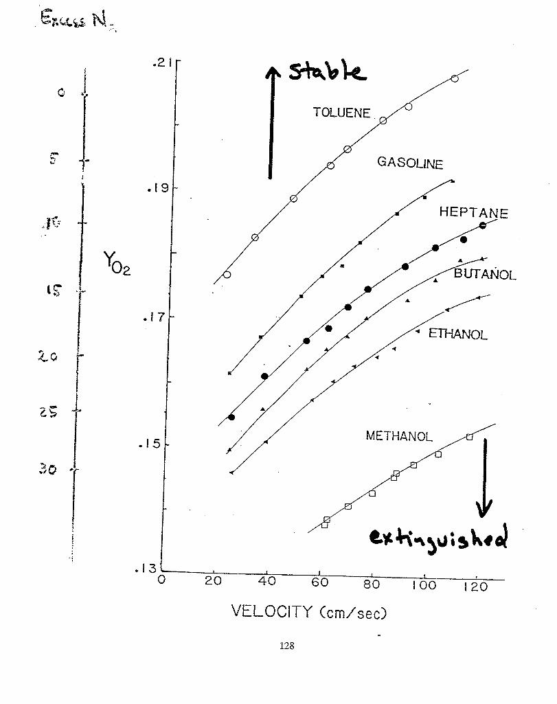
%2 /4
b S+d9k
/
TOLUENE
GASOf_INE
-f
. 13L 10
I20
!40 60 /30
! vI 00 120
VELX.X17Y(cm/’sec)
128
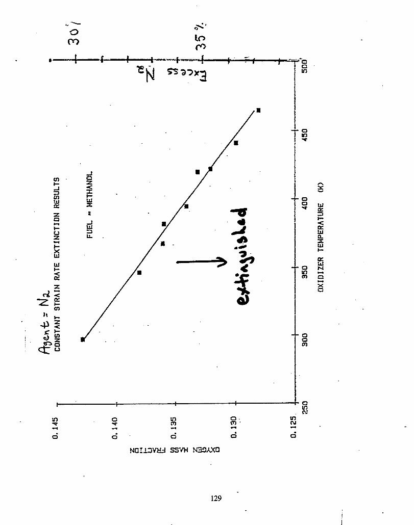
n
/’ .
Inm
6
S!3M
a. tfim“ al
6 0“
N3’zlx(n
129 -
IL. ___

—
t=uaHEGH-rAausmDEEC.E
7—
.[48 cm
.-
!..-../---.-=-...-.
FUR
Ffr?Excl—lmEY
e-”II
‘---l;-p
RR(X.P L!/!(28m OD)
J-UhSS BEADS
> ..-..
.“
:-X. :’.: “ . .“-.3 -. ‘-
Ii11II1!
IIII[1IIIIIIIIIIII
130

u’)
E%lmln
❑la
u)
0u)
mc)
ml
J=!P!X
OU
!
ZZ
-3A3H
SZI--W
H,
-“’-3’-“’’-3’3”
81
iiiiEii 9C
Z-04H
.-..:.:.:.:-:-:.:-:.:.:.:.:.:.:.:-:-:.x.:.:.:.:.:.:.:.:.:.:.:.:.:.:.
=LZ
Z-3’H
4 ....... .:.:.:.:.:+..:.:,:->:.:<.:-:-:-X
.:.:<.:<.:.3:.!-:.:.:.:{.:
I1
I1
,..................................1
II
II
t!
1!
II
11
0CN
40
131

2. FLAME STABILIZATION BEHIND AN OBSTACLE
-.
%-
0
40
30
20
10
0
Fuel =Heptane j
L 4 b
I

..__ —_-..,:, - .
Flame Stability in a Recirculation Zone
Parameter I increased Stabilitv I
velocity decreased
temperature increased
1Pressure” increased
turbulence decreased
equivalence ratio flammability peak
flame-holder size increased
flame-holder increaseddrag coefficient
geometric blockage increased
fuel volatility increased
atomization finer
I

..
r
(/2.,
coaA(!J
....?..
.-. ”...,
<,.
.“,
.,-.....
..
.“..;
,.-.
..i.-.,....
.,:!
...x
......
..
:I-
2.
. z+.,.UJ
..C!s
‘aua
LL
lm3i-
Ec)
+
134
Lu
-1n3000Eawr#-

D
Recirculation Zone
I-+:=1
IFuel Tube
45° hcone
OHOWspray
I““Bluff Body
R= Z7-9 R=- ,3-6

,.
.-—.
..-
aI
II
II
II
II
Ii
1I
11
0mu
)
E00r-nu
’)II
76>LCD
c--
MI
--l
E
H-/0m
l
u-)
—0—Ln
>-w’
--c-)0
r-
U’k
Lf)r-C
’-qC’4
—(”4
&__ll
hL-CD
>--
m>
ta)u
uI
I1
1I
II
II
1I
II
II
II
II
n0
Ln
0N
m0“
——136
(b)
SWq/J

vu)O
.JCN
I1
1t
I1
1I
II
1I
II
II
If
•1
1
+
aI
I1
II
1I
II
1I
II
II
o0
00
d-
o-
r)o-(No-
—o-
00m00000d-00(N
00
(nEz>(-a)
c>LCD
>--cl)n
00-

AGENT ENT~I=NT INTCI RECIRCULATION ZONE
@ Predict Xi as function of At., Velcni.ty
Assum~ticms
~ TO extinguish flame, X~(At) > XC.
@ Zone length (L) assumed cxmstan.t.
0 lnstantaneOus mixing OCCUrS.
O Spray characteristics unimportant.
.. .
138

Results
xc(At)
@At= injection interval.
@ X. is not predicted but is a function
of agent chemistry.
139

.,,>-
..-.
Ln
@d
-(!).%
II=4-J
c%<
(
r ❑3c)k
-r---
%--
00CD
onC--JU7
~E
11!1,1,,,,1,,,,!,,,,,,,,,
Ino
mo
u-)
oN
o—
J——
——
—0
:0-
0“
o-0-
0-
0-
-3x
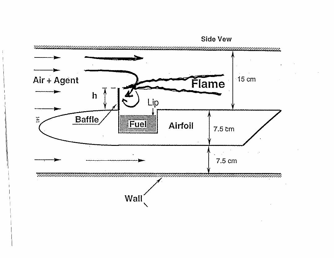
SideVewy/ys\ ~\\\\\\\\\\\\\\. ~\?N.\\\~ .
Air + Agent 15cm
h
‘x
A .
7.5 cm
\{
\
I

160
i40
120
I(J
Ou 4U JU Z(J 10I I I I I
.
5/8 ifn.p[ate
/
o Trnrn)
o
/#’
/“/”. ”
2 in.p(ate
/’7? 1mm)c)
-o
~r~ssu~e ahThe effec-ates at the front o
tank (kerosine)

....
8
----2--,-n
:..
.nn
I
3o—If)
o
:--1-u
a)
E--f-CD
I
u1
II
1I
I1
11
[I
II
If
II
!I
1I
I1
I1
If).0
u)
0N
u)
0N
——
1[

‘d
-73c-r--
c--
LL00n
00l-d
11EgLn
010
V4
y
8xII
x“
EE0ma
.EEmr-X
11I
1I
I!
II
1I
ff
I1
I1
I
om
mC
N’
(auq
oA
1I
II
Ii
II
ii
b
I
-J
!I
1I
1I
II
1!
!
0u’)
0
m‘dmNo
‘7aE8-1-
s-Isu).-S2
37
c
144

102
10
n
(nw 10P’
s.U
0,10
0,010
t I I I I I 1 r
1=
E
I I I 1 I 1 I i I II I I I I 1 1 I I-J
●
✼
I @obstacleinmiddleo obstacleagainstwall
●
r
d = 0,035 m\
-4
I 1 t I I I I I 1 I I 1 I I 1 1 1 I I I I I 1 1 I I I IO*O1 0.1 1 10
Velocity(m/s)
. . .

CONCLUSIONS
~ In general, baffle stabilized pool fires are moreclanaerous than baffle stab.ili.zecl spray fires be=-cause:
1. Long mki.ng times associated with agent entrai-nment into the recirculation’ zone of an obstacleagainst a wall.
2. Higher agent concentration is requiredextinction.
to achieve
A fire of this sort may occur in an engine nacellewhen a fuel puddle is located downstream of a rib.
O A fire with a heated oxidizer flow requires moresuppressant to extinguish.

,
SPECIES CONCENTRATION MEASUIIEMENTS
William M. Pitts,Building and Fire Research Laborato~
National Institute of Standards and TechnologyGaithersburg, MD 20899
. .
Coworkers: George Mulholland, Brett Breuel, DickHarris, Mike Glover, Darren Lowe,Steven Chung, Rik Johnsson, YonasMakai (PL), David Hess (CSTL)
Solid Propellant Gas Generator WorkshopNISZ June 28, 1995
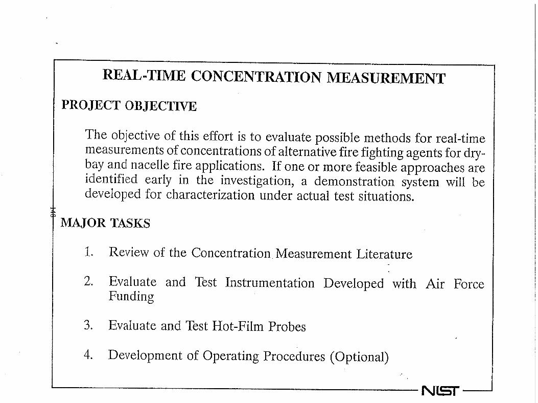
.
REAL=TIME CONCENTWTION MEASUREMENT
PROJECT OBJECTIVE
The objectiveof this effort is to eva~uate possible methods for real-timemeasurements of concentrations of alternative fire fighting agents for dry-bay and nacelle fire applications. If one or more feasible approaches areidentified early in the investigation, a demonstration system will bedeveloped for characterization under actual test situations.
WOR TASKS
1, Reviewof the Concentration. Measurement Literature
2. EvaluateFunding
3. Evaluate
and Test Instrumentation Developed with Air Force
and Test Hot-Film Probes
4. Development of Operating Procedures (Optional)
NH —

,
1 ●
2 ●
3 ●
4 ●
..
5 ●
6 ●
OUTLINE
Introduction
Fire Extinguishing Agent Senso(FEAS)
Differential InfraredSensor (DIRRACS)
Rapid Agen
Combined Aspirated HotFilm/Cold-Wire Probe
Statham Analyzer and Halonyzer
Literature Review
NET

TIME ~SOLUTION REQUIREMENTS
Dry-bay application requires fire extinguish==ment in tens of milliseconds.
in order tobehaviormustmeasurementsevent.
)!
characterizeconcentrationbe ableto make real-timesignificantlyfasterthanthe
A temporal resolution ofone millisecond (WZ data rate) was chosen as design goal
Note thattherequiredtemporalresolutioplacesconstraintson spatiallXXOlUti013e
Compare currentrequirementwithralresponseofexistingStatharn.andyzerinstruments(0.25s).
temptHaIon

,,!.:.
1
I
‘.!::.:
r
..
John Brown Associates FireExtinguishing Agent Sensor (FEAS)
‘o’),1
.
Hot Wire IR Source
~mmniumwindow
II~lR Radiation
~_
-..........
Light Guide
,Narrow-BandpassFilter
PyroelectricDetector
Op Amp CircBoard
.
:uit
NW –

*
FREQUENCY RESPONSE OF THE FEAS
10
8
6
-4
..
2
0
l“’’’’’’’’’’’’’ 4’1’1’’’” ‘i”-
,s
-/
L’-
.
\
\
\
\
\
\
b\\\
\*“ –*
\
\-8 —— +
, I , , 1 I , ! , I I f ! I ! , t , 1 I , ! ! r I f f d) 50
Frequency
100
(f-k
150

,
.
SCHEMATIC FOR THE DIFFERENTIAL INFRARED_lUU?ID AGENT GONCENT–WTION SENSOR (DIR–WCS)
Power .
‘~~15’m_N’’~>%Y f:::,
II‘// 1 1/4 NPT I1[ { / ‘i’’ing Ii1n--- ‘
/
..-
n- -[!.-–.—Vlluppcl Zns
‘F\~oolmg
Window CoilZnSe
~otlwl: Window
--l 1+2.8 cm
,.
NH —

,
eoP-
mm
wm
N
C5
6T
-
0G
60“6
00J
000m000*000N0000=T
mm
Y--
aT
-ed
me
0“6
C5
90
00
6:
:1
1
(AA
-y~)oA
fA
bz

,
1
0.9
0.8
0.7
0.6
0.5
DIRRACS CALIBRATION
. .
, I , , I , , I , I , I i I 6 I , 1
I
o
\
,
--e- Test
----x--- Testi.- A- - Test
– E- - Test
#l ]#2#3#4 {
“\...........
0.05 0.1 0.15 0.2 0.2:
MoIe Fraction HFC-I 25
N(ST
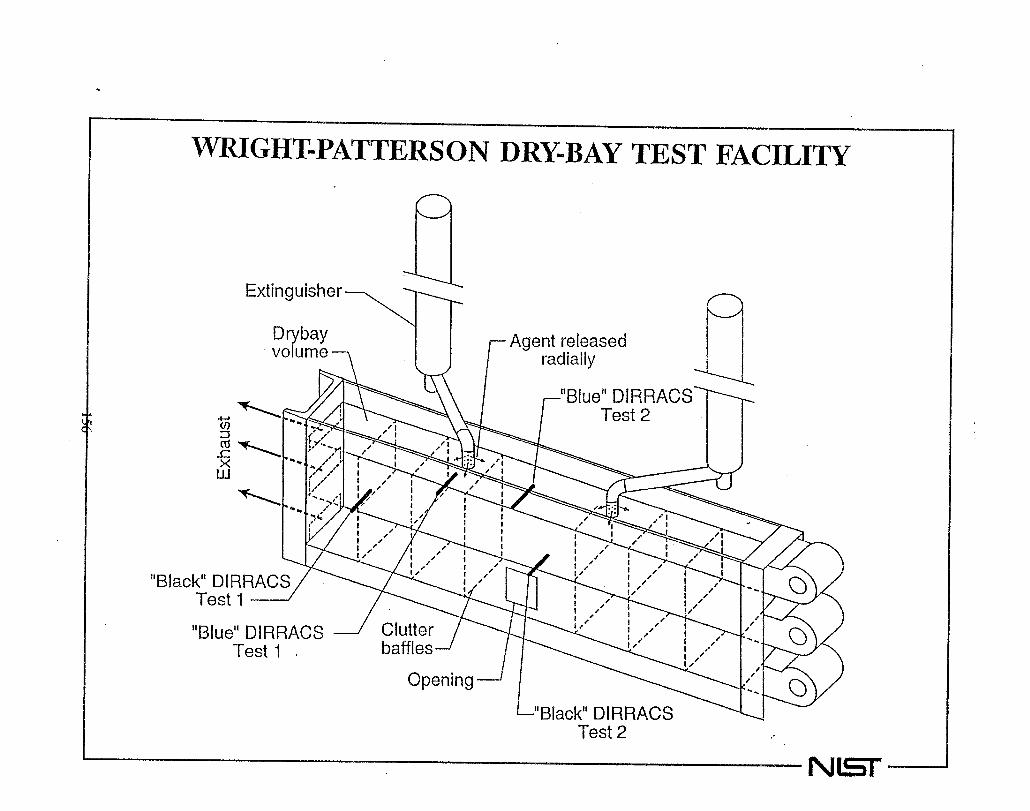
,
...L
Ju
..
I ‘\\\\\----
\\,-
W

./.
r
oC9
..
CONCENTRATION MEASUREMENTSJRING AGENT RELEASE INTO VVRIGHT-PATTERSON AFB DRY-BAYFACILITY
0.05
0.04
0.03
0.02
0.01
0.00
)1
, I 1 , b I , I , , I i , , I I
1t , I , 1 , I , I , I
o 2. 4
Time
6
(s
8
1 c-l
10
NW

t
DIRRACS CONCENTWTIONTURBULENT SPWY-FWE
MEASUREMENT INBURNER FACILITY
0.12
0.08
0.04
0
1 r , 1 I
~ ‘{“’’’4 t , ,
B1ue
!\,(●V!I ‘\f.I
\4+------
t\I
I
t
I
II
I
t
1
1
1t [
I1
t—
1
i
Ii 1
1 II t
t\
I I t I ! , t ! 1 I , , ! I I , , I 1
0 0.5 -1
‘Time
1.5 2
1<0 NET’

*
*
CURRENT STATUS OF DIRRACS
O Feasibi ity demonstrated.
● Sensltwity to flow ve ocity musteliminated.
Reductiondesirable.
of sampling volume 1
..
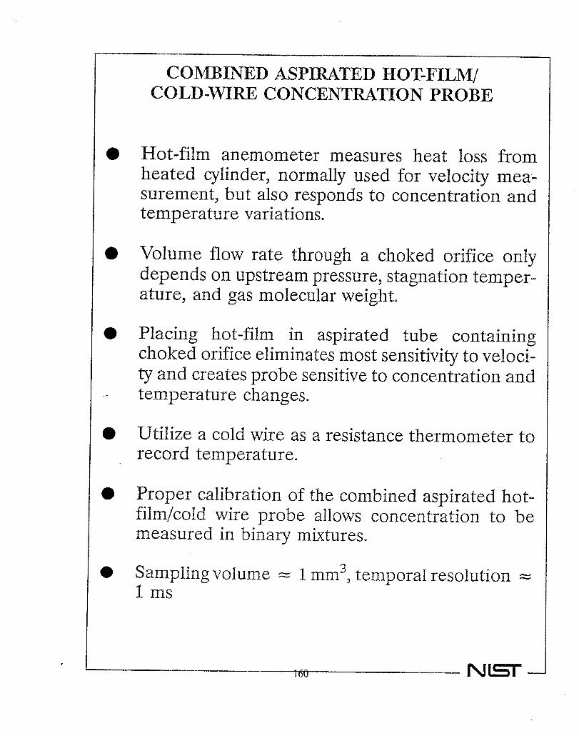
r
o
●
o
0
*
e
COMBINED ASPIWTED IK3T-FILM/COLD-mm CONCENTWTION PROBE
Hot-film anemometer measures heat loss fromheated cylinder, normally used for velocity mea-surement, but also responds to concentration andtemperature variations.
Volume flow rate through a choked orifice onlydepends on upstream pressure, stagnation temper-ature, and gas molecular weight.
l?lacing hot-fihn in aspirated tube containingchoked orifice eliminates most sensitivity to veloci-ty and creates probe sensitive to concentration andtemperature changes.
Utilize a cold wire as a resistance thermometer trecord temperature.
Proper calibration of the combined aspirated ho~film/cold wire probe allows concentration to bmeasured in binary mixtures.
Sampling volume ==1 nun3, temporal resohtion =41 ms
NET

COMBINED ASPIRATED HOT-FILM/COLD-WIIU3CONCENTRATION
0.51\
1.25
c+..&
J-
PROBE (TSI
Vacuum
t )1
MODEL 1440S)
Hot-Film
T_w0
H.00
Cold Wire
* AH Measurements are in mm
—

..
&u75>
-w75(J
6
4
2
0
–2
-4
–620
Co d–Wire Calibration
= 62.670 + 74816V
40 80
Temperature (“C)
100

,
*Q
5.
4
3
2
1
0
Asph-ated Hot–Film CalibrationI I I i i i
,t
4-WC .O.- -35°C.O.O
● ●O-25V ● ●.*OO-15°C ● ●
● O.*.-5”C**.0 ● ● ● ●
. +5’v*o@090 : ●
● O*+15°c●* g o,. *9*
+25”C*00 ● ● ●
●*.-O ..
.
● ✍● ☛☛
●
–0.2 0.0 0.2 0.4 0.6
Mo
0.8 1.0 1.2
e Fractionof Ha on 1301
103 NET

..
%-0
n
0i-a-
0.2
0.1
0.0
–0.1
–0.2
–0.3
–0.4
–0.5
NORMALIZED PROBE RESPONSE
vv
vv
Tv
v
v
v
v
e HFC–1 25v halon 1301v FC–218u HFC–227
24.5
I
0.0 0.2 0.4 0.6 0.8
Mole Fraction of Agent
c
v
1.(
NE

,
a)
co..—
2ua)
O.10
0.05
0.00
–0.05
DRY BAY RE .EASE #1 ..
.
1
II I I 1 I I I I 1 I01234567 8
Time (s)
9 10
NET

r
.
0>-+-J
z0
E—-.—I-L
I0r
4.0
3.5
3.0
2.5
2.0
1,5
1.0
0.5
0,0
-1
-+
=+1
“ +’2
+3
O“c1“c
1“c
1‘c
1“co00
iii
*
o00
ii
o00
ii
o’‘Before
* Afkr-T
o00090
Test
o0008
+3°C
+ 13°C
g +13°C
* +33°C
–0.2 0,0 0.2 (),4 0.6 0,8 1,0 1,2
Mole Fractionof I+alon1.301

,
0r’)
.. 7
0.20
0.18
0.16
O*I4
0.12
0.10
0.08
0.06
0.04
0.02
0.00
.
.
i
i
..:. -...+ — ..e --------- .---~ a
. . -------
,
I1
IIi11i1I1LMIIII
il88,,
.:..:.:-.
-r.
‘1I ‘L b ,241 ,ms\\ -.,. ‘&4.:*zn-::*-:---k
(‘%142 ms
-.~.:.e.+
86 ms
1 I I 1 I I I
0.8 1.0 1.2 1.4 1.6 1.8
Time FollowingRelease (s)

,
CURRENT STATUS OF COMBINEDASPIRATED HOT-FILM/COLD-~~
PROBE
Probe is sub@ct to cloggipgdry-bay tests (attributed to
duringuse of
actualsauib
e
charge).
Probe has anvelocity fluctuat:
unexpectedOnse
A
sensitivityto
ofagentco-ncentrationProbe is capable of accurate measurements
h high temporaland spatial resolution.
wi-
Probe sensitivitysidered.
depends
O Additionaldevelo~ment
ongas
might
~airs
lead
con-
to :probewhichcoul~be usedindrv-bayan~nacelletestfacilities.
J
NEr

,
SCHEMATIC FOR A “GAS ANALYSIS APPARATUS”REPRODUCED FROM THE UNITED STATES PATENT
OF Y~IKOSKI (1952)
2,586,899GASANALYSISAPPWTUS
F:led Oct. 18, 194S - ..
>1
n (2 n f’ /’-4
..
> ILL .3
15
=%%%%47$160 NH –

,
..
--z7is
800
780
“760
’740
?’20
’700
680
660
640
620
6000
HalonyzerResponseTimes
,1
●
eI i I I I I 1
[234567 8
TubingLenght(m)
Response times for a Halonyzer concentration reading to change from Oto 95% for a stepincrease in halon 1301 mole fraction to 100?%as a function of sampling tube length. Dataprovided by W. Meserve and D. Van Cktrand of Pacific Scientific.
1’70

,
11.5 Literature Search For Additional Diagnostics for High-Speed Alternative-AgentConcentration Measurement11.5.1 Introduction11.5.2 “Standard” Chemical-Analysis Techniques
11.5.2.1 Gas-Solid and Gas-Liquid Chromatography11.5.2.2 Mass Spectrometry.11.5.2.3 Standard Optical Absorption Techniques.
11.5.3 Fiber-Optic-Based Measurements of Concentration11.5.3.1 Introduction To Fiber Optics.11.5.3.2 Spatially Resolved Absorption Concentration Measurements Using
Fiber Optics.11.5.3.3 Other Fiber-Optic-Based Concentration MeasurementApproaches.
11.5.4 Additional Optical-Based Techniques11.5.4.1 Raman Spectroscopy11.5.4.2 Coherent Anti-Stokes Raman Spectroscopy (CARS).11.5.4.3 RayIeigh Light Scattering.11.5.4.4 Fluorescence Concentration Measurements.11.5.4.5 Mie Scattering Concentration Measurements.11.5.4.6 Specialized Concentration Measurements Based on Optical
Absorption.11.5.4.7 Optical Speckle Technique.11.5.4.8 Miniature Mach-Zehnder Interferometer,
11.5.5 Acoustic Absorption
NET —

..
TECHNIQUES RECOMMENDED FORCONSIDERATION BASED ON
LITERATURE REVIEW
Time-resolved mass1
spectrometry.
withMid-infrared absorption used in conjunction
fiber optics for spatial resolution.
Near-infraredabsorptionusedinconjunc-tionwithfiberopticsforspatialresolution.

OXYGEN CONCENTRATIONMEASUREMENTS USING
DIODE LASERS
David BomseSouthwest Sciences,
Santa Fe, NM505-984-1322
Inc *
Gas Generator WorkshopNIST
June 28, 1995

I
Qo6u)
o.—Ii0
P“
u)
rxLLlco‘a-1Illc10
ii
c)z0zL“
x0r!?
a)Lu
)
GE
‘Qa)
u=E
a)c.—ms*—(/
)
c—
c-
0.—c1wco3>13
0L.—>
a)Cfl
mal
zuR
I
00
Cn
s.—(/)
cCD
co
c0!2coa)
$-
m—*—>.—❑
�(nc(1)C
n
>co
al
73’)
US
C.—
CD
c)(uL.
-ua)u
’)
.-C
D
5ECD
ix
iii
0QcclL
0)+.+-1
-+
-+
e
174

OPTICAL SPECTROSCOPY
DETECTOR
!3LIGHTSOURCE
4L
>
>
T1
— = exp (-n @ = exp (-Q!)T10
I 1
SENSITIVITY DEPENDS ON (XM,~

I--’
CL0
3Lu
z—>—1-0LLl
JLL
lcoLu
n—>0ccCL
CK
Lu
“--
<‘3
I
---i
t
=3-1J
---1
176

WMS DETECTION
Increase Sensitivity ByShifting Detection Bandto High Frequency
Modulate Laser Frequencyat f, Detect at 2f
oTransmittance
mgoCt
on -60 -Ill~ -80 ‘ ---------------------o= -100 I I I I I I I I
1 E+O 1E+2 1E+4 1E+6 1E+8
FREQUENCY (Hz)
Advantages of Diode LaserWMS:
Exceptional Sensitivity WI 0-7
Selectivity Av -.001 cm-’
Rugged Solid State Device
Fiber Optic Compatible

WAVELENGTH MODULATIONSPECTROSCOPY
zcm
I
f4
DC POWERSUPPLY
MODULATIONSOURCE
DETECTOR
12f MIXER orP
LOCK-IN
+

GAS DETECTION LIMITS
Q 10 cm path length & 10 msec response time
DETECTION LASERGAS LIMIT WAVELENGTH
o2 800 ppm (761 nm)
HF 0.17 ppm (1321 nm)
co 275 ppm (1565 nm)
C02 430 ppm (1602 nm)
HCI 0.75 ppm (1740 nm)
HCN 25 ppm (1548 nm)
NO 2 90 ppm (760 nm)

u’)zo1-<c)
L?
a)
CD—
E0k.u)
a)9
a)casz5z*
180
CL
xCDs0aE0u0
L0m—c0EmQ0m.—L-
Zi5
3TJc*

Oxygen in 1 atmosphere air20 cm optical path
10 msec response time
—
Laser wavelength
Southwest Sciences, Inc.Santa Fe, NM505-984-1322

INSTRUMENT DESIGNUSES PATENT-PENDING DUAL MODULATION
LINE REFERENCELOCKING + - - 75 ETL- -
v
wGOtd
MODULATION
* ‘SE’J ‘In.—___I
2ndII
MODULATION I pitch I
J
! and I:: catch :
Ireference I
2ndDEMODULATION
I
reference
testsection I
I__ –___
> (to computer)
photodiode
ABSORBANCE SIGNAL

USAF SPGG AdvancedDevelopment Program
1. Structure
A. Phase I
B. Phase IIw00uC. Phase Ill
Il. Issues
Ill. Conclusions
IV. Questions
I

II
Structure of the Program
Phase I
--optimization for transport aircraft
--testing/modifying in AENTF at Wright-PattwE
Phase H
--system tests
--testing at Davis= Monthan AFB
Phase Ill
--flight testing at Edwards AFB
--final report preparation

Optimization
--test bed will be
KC1 35-R
+00 Testing at AENTFU
Phase I
CFM-56 engine found on
--many conditions within an engine nacelle will
be simulated
--analysis of physical relationships)>naceiie volume vs. propellantrequired>>airf[ow rate vs. propellant required
>>air temperature vs. propellant required
--data obtained on concentrations
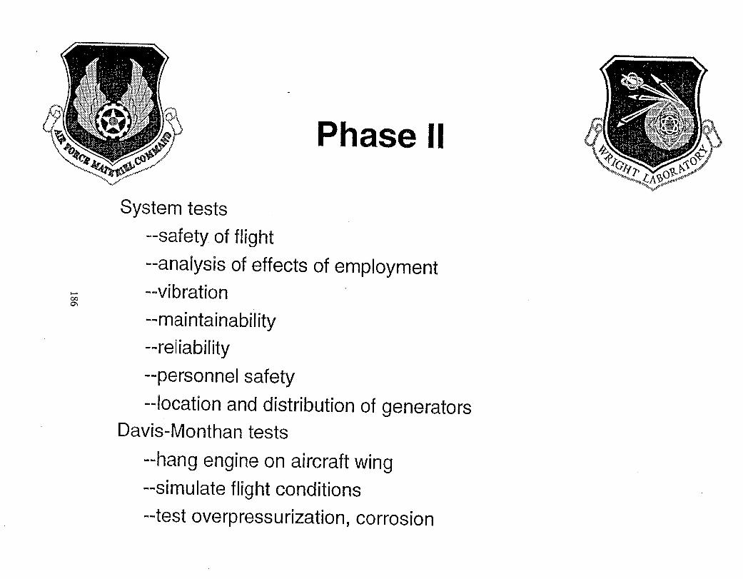
Phase II
System tests
--safetyofflight
--analysis of effects of employment
w --vibration%--maintainability
--reliability
--personnel safety
--location and distribution of generators
Davk-Monthan tests
--hang engine on aircraft wing
--simulate flight conditions
--test overpressurization, corrosion

Phase Ill
Flight testing
--flight demonstration vs. qualification
--in-flight dischargewm4 --verify system compatibility
--long-term effects on propellant
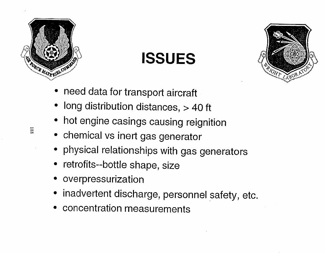
ISSUES
* need data for transport aircraft
0 long distribution distances$ >40 ft
o hot engine casings causing reign ition+4mm * chemical vs inert gas generator
o physical relationships with gas generators
o retrofits--bottle shape, size
@overpressu rizat ion
* inadvertent discharge7 personnel safety, etc.
o concentration measurements

al
u)
T7ccd
a).-C
6
u)s0
ss00
0.-u
)u
)c0.—+.-Uc
EU
)s
a)0cc1)u
)cd
Q
u)
Ea)E
C6
CD
N.—(n~s.—cdE
u)c0
c0$)
Cn
.—5u.—-5Qcd
c.—aEs
0alu
)C
’6c0
0.-
C0sm.—
cdmS.—N.—y)
vscd
.—cdi1
I11
1
189

,
NVMI.. AIR WARFARE CENTER
INERT GAS GENEFL4TORSUsed for Fire ProtectionAboard Navy Aircraft
Sponsored Bv: Tames Homan
N;val Air
Presented
Sy;tems Command
By: Marco Tedeschi
Naval Air Warfare Center
Aircraft Division Lakehurst
June 28,1995
Naval Air Warfare Center

A*+%aNAVALAIR WARFARE CENTER
AIRCRAFT FIRE PROTECTIONAPPLICATIONS
+ FIA-18 E/F
– ENGINE NACELLE
– DRY BAY
+ v-22
– DRY BAY
Naval Air Warfare Center
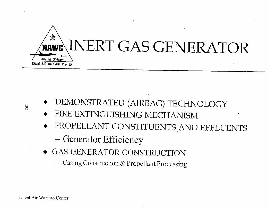
I
AhlX3fiDltision
N/W. AIR WARFARE CENTER
RT GAS GENERATOR
● DEMONSTRATED (AIRBAG) TECHNOLOGY
~ FIRE EXTINGUISHING ME~HANISM
~ PROPELLANT CONSTITUENTS AND
– Generator Efficiency+ GAS GENERATOR CONSTRUCTION
– Casing Construction&Propellant Processing
EFFLUENTS
I
Naval Air Warfare Center

F/A-18E/F ENGINENACELLE TESTING
NAVA1.AIRWARFARE CENIER
+ TEST ARTICLE CONFIGURATION
+ TEST CONDITIONS & PROCEDURES
– Variable Distribution, Sequence, Number ofGenerators
+ RESULTS AND CONCLUSIONS
– Four llb Generators @ 1500 ms
Naval Air Warfare Center

F/A-18E/F DRYTESTING
NAVAL AIRWARFARECENTER
BAY
+ DRY BAY SIMULATOR CONFIGURATION
~ + TEST CONDITIONS & PROCEDURES
– Variable Threat, Number& Locations ofGenerators
+ RESULTS ANDCONCLUSIONS
– ‘7Generators Sequenced 2,2,2,1 @ 10
– 50% Effluent by Molar Dispalcement
Naval Air Warfare Center
ms intervals
Method

Ahcraff Dhlskm
NAVALAIR WARFARE CENTER
V-22 DRY BAY TESTING
+ TEST SET-UP AND CONDITIONS
+ TEST PROCEDURES
– Various Dry Bay and Gas Generator Sizes
+ RESULTS AND CONCLUSIONS
– 525g Mid-Wing, 250g Aft Cove Generators
– 100% Effluent Concentration By MolarDisplacement
Naval Air Warfare Center

. .
TECEthTICL4LISSUES
CONCERNSNAVALAIRWARFARE CENTER
+ CORROSIVE BY-PRODUCTS
wU2m
AND
+ SINGLE GRAIN PERFORIVJANCE
– Decrease Pill Erosion, Lower Weight,Manufacturability, and Performance Concerns
+ SYSTEM QUALIFICATION/ EFFLUENTCONCENTJ?ATION
– Gas Measured with ‘Continuous’ Response
Naval Air Warfare Center

.,
I
I
NAVALAIRWARFARECENIER
CONCLUSIONS
PROVEN HIGH EFFECTIVENESS
Naval Air Warfare Center
AIRCRAFTMINIMAL WEIGHT & VOLUMEIMPACT TO
REDUCED MAINTENANCE
ENVIROMENTALLY RESPONSIBLE
FUTURE NAVY AIRCRAFT
NEW APPLICATIONS

.. ..
+ Navy Qualification of SolidPropellant Gas Generators for
Aircraft Fire SuppressionNAVALSEA SYSTEMS COMMAND
Presented to theNational Institute of Standards and Technology Solid
Propellant Gas Generator Workshop28-29 June 1995
byPhilip Renn, Code 5210??
Indian Head Division, Naval Surface Warfare CenterIndian Head, Maryland 20640

oa)
-
0n
=&
0u
c1-
0E$E
sa)
Ea)mCG
cmE
coc0w
-53
nEa)
7.00
QLn
>%U)
nann
a)E0Ii)
a)G)
s
n‘5)
ca
msa)
a(ill)d●
●●
199

a)>E
-t)a)
0
0
a)zc“0I-(08->a-QvC
Ga)r
-
200
Pu
’

tia“
Ea)&
c-“
Q)
LCG
u)
LomLa)sa)
0u)
CG
0EC5
cl)Ea)
E00u
)a
)a
)Q
)u
)u)C
Gu
)co
a)
kcl)
a)x-
c0,-U
a)>
d)
‘&toaLal)
ua)
IA
d
iii)n●
Ii
ou)
201
w
. .. . .
FSC 1377 items are tested to therequirements of:
MIL-D-21625 Design and Evaluation of Cartridgesfor Cartridge Actuated Devices.
MIL-I-23659 Initiators, Electric, General DesignSpecification for
MILwSTD-1385 Preclusion of ordnance Hazards inElectromagnetic Fields; General Requirements for
Specific aircraft system specification additionalrequirements
MIL-STDU2000 Propellant, Solid, Characterization of
NAVSEAINST 8020,5A Qualification and Final(Type) Qualification Procedures for NavyExplosives Materials

-----
wow
Navy SPGG Test Program● MIL-D-21 625 provides over-all design evaluation
.
.
—
—
—
—
—
—
Design and construction requirementsExplosives selectionElectrical requirements (MIL-I-23659 & MlL-STD-l 385)Service lifeLogistic issues (Nomen.,NSN,HC, DWG,markings,etc)Design Feasibility Testing (DFT)Design Verification Testing requirements (DT-IA) (establish designfreeze)Service Release Testing requirements (DT-llA)(Qualification)Packaging requirementsData requirements
● MIL-I-23659 and MIL-STD-1385 provides for electrical requirements– MIL-I-23659 provides for design requirements and handling safety– MIL-STD-1385 addresses HERO requirements
● The contractor system specifications provide for additional testing notcovered by the military specifications and standards
– Explosive atmosphere– NBC– Fluid exposure
I
,

Hazards Of ElectromagneticRadiation on Ordnance (11-IERO)
e
MILMSTD-I 385 primary HERO specification
NAVSEA OD 30393 HERO Design Guide
HERO referenced in MIL-I-23659MILuD.21625
and
Naval Surface Warfare Center, Dah grenHERO authority for Navy
HER() driven by shipboard EMIRFenvironments
HERO addressed at system, cohandling levels
is
nponent and

Explosive Hazard Classificatim
CFR 49 Parts 100-199 Transportation
NAVSEAINST 8020.8B DOD Ammunition andExplosives Hazard Classification Procedures
– Joint DOD Explosive Safety Review Board
Current SPGG HC is 1.3C (Class B) from DOT
Goal SPGG HC is 1,4C or S
– Less
–– Less
restrictive storage requirements
costly transportation

a)
“zx
m-
a)m
-C
DL
Qm
00
0ms
1-0
alU)
3a)
Sa!)L
0Ea)
CA
a)1-
iii”(3sQ1-g
gUI
m
x-3v’a)L
m-
QE
a)1-
CG
~E-
u)C
G8R
‘a(usL
u)9->
aLa)co
Q0u)
Lal)
m0m>
LL
lc
8-
d1-xQ
a)mCG
m
>>CG
z
a)5m3(3
al>s
9
a)u)
$206

I
I
-,
SPGG PROGRAMS
● Current Programs:
17 SPGG (4 configurations)
Program:
– F-18EIF 7 SPGG (1 configuration)
– MV-22
● Potential
– F-22
– KC-136R
● Future Programs:
– JAST
–– Second source plans
1 I

EXPLOSION SUPPRESSIONFOR INDUSTRIALAPPLICATIONS
by
Franco TamaniniResearch Division, Explosion SectionFactory Mutual Research Corporation
Prepared for Presentation at the Solid Propellant Gas Generator WorkshopNational Institute of Standards and TechnologyGaithersburg, MD, June 28-29, 1995

GENERAL BACKGROUND
a PROTECTED SYSTEMS
* Laminar and turbulent vapor/air mixtures (propane typical).
* Dust explosions for ST 1 & 2 dusts (K~t<300 bar m/s).
* Test data for volumes up to about 250 m3.
* Proprietary design methods developed by hardware manufacturers.
● TYPICAL CHARACTERISTICS
* Several types of agents used, including powders (Sodium bicarbonate,Mono-ammonium phosphate), water and pressurized liquids (Halonreplacements). Water unsuccessful in suppressing gas explosions.
* Suppressant quantities of 5-30 liters per unit. Several units may berequired for one installation.
* Suppression system activated by UV or pressure detector.
* pressu~z~g agent, typically ni~ogen, at 40-60 bar (600-900 psi).
* Activation tfie: 1-2 msec. Agentdelivery time:1()-10() msec.
209

EXPLOSION SUI?PI?.XNS1ONRESEARCH AT FMRC
GOAL
Develop an understanding of the mechanisms of explosion suppressionand establish the effectiveness of new agents, or new. deliverymethods, in suppressing high-challenge explosions.
COMPLETED WORK
Carried out suppression tests in the 2.5-m3 pressure vessel for near-stoichiometric methane/air mixtures -usingmono-ammonium phosphate(MAP), sodium bicarbonate (SB), and water as suppression agents.
The two powder agents (MAP and SB) were found to be successful atsuppressing explosions in both quiescent and turbulent mixtures.
No successful suppressions obtained with water.
WORK IN PROGRESS
Perform additional gas explosion suppression tests by experimentingwith novel delivery methods to maximize the effectiveness of wateras a suppression agent. Propellant-based gas generators seen aspresenting a means to improve effectiveness of water.
210

EXPLOSIONSUPPRESSIONRESEARCHAT FMRC
● EXPERIMENTAL FINDINGS
* Inerting concentrations of the two powder agents from 20-liter spheretests with a 10% methane/air mixture:
Sodium bicarbonate (Ansul Plus 50C): 975 g/m3Mono-ammonium phosphate (Ansul Foray): 575 g/m3
* Suppression tests in the 2.5-m3 vessel performed for the followingparameters:
Amount of suppression agent: 3 KgPressure of driver gas (nitrogen): 50 bargDetection pressures: 1, 3, 5, 8 psig (0.07, 0.21, 0.34, 0.55 barg)Mixture conditions: Laminar (ul = 0.42-0.58 m/s)
Turbulent (ut,~ = 1.14-1.71 m/s)
* For the single concentration used (1,200 g of agent per m3 of protectedvolume), the two powder agents (SB and MAP) found to be alwayssuccessful in suppressing the explosion and to have similareffectiveness.
* Failure by the water to achieve suppression in most runs. Noappreciable improvement from the use of nozzle with smaller injectionholes and addition of COZ to the nitrogen charge. Full unventedpressure developed by explosions where suppression failed.
* Location of the ignition source found to have a small effect on theperfomnance of the suppression system. Surprisingly, mixtures ignitedbehind the injection nozzle are the easiest to suppress.
* Increased challenge to the suppression system due to presence ofturbulence in the mixture, leading to higher suppressed pressures.
211

*
1. FM31C 2.5-M3 FACTLITY
EXPERINfENTAL FACILITY
*“ Ion:tion Pmar+,
I I
2. SUPPRESSION VESSEL/PIPING
3“ 3000* Fmmd Stl1/4 “ 3000= &Thd”d Hal F-Cplo.
cFcng-d SLI .
Thd”d Fk,lf- ~ ~L4- Cm-b. SLI.
.:coup 1 I “a
k
/.+..._P. . . . . Wald,,w P,pm CcIp......
~.’
T
——.. -----
......—.-. _ ....- .......__. -.-”..-.
I!
7.. am . %!.,,.. 7-7’
3. sad. al
Q.-. Mt.
* c-.. I-Id. E1b.-
U. Su. T*
!-L)
3. INJECTION NOZZLES
.:-.-......-..
Liz
Drill Inq Pott=rn for lsL Nozzle
mm: All Ho I.. Le k.- 1/0- o,.. . C,e.,r.md BJT)+S,d.. . T- L.! F&.. %1-. - 282.
3-. Ssl”d. m *,., +,.- c.. . .5. .
P‘3-—_ s,-..
&’-. ‘; ::;\&: .,qj-, – ‘“’+---.:,..
m--- —
3.7s. 0.0.
x l.c. h
T.A.
I, /=, hi-. ?.5”. 1-7/16- R.

.,’..
.~‘\
.
[,..,>
4Li
-h
0-lJ-U
I
e“14Hm12
\
YwO-J
mI&l
>m
ml
0-+-30.
.xIP
213

;.
/%mo0<i-i
‘%m‘--l.-
i,0
~...
0
rT4=
--=-7-—
=—
~—
‘c-t-f-l’,
,;
.,-
f.=
/L
iii.:4-J
:<,[-,..
..I
l-j1’ --4
L-
!1’”r-l
I
-a,-
-\:
si-
-1.-c
J!-“%
,,.
-u
.(-:-
‘)+
.
u-)0
y-UI.0
10
..
xr=-
214

mc-u
aoamC
L=
&[.H
I d’‘$Lmti=
1
Ii
—
1111
P-J-e
i
2.,
cti-
0u.rlfnE0Cu
-“(m
.
x-.?
-4
xi“””
u-0
L.I-i
a\m-
....,...
0.
c
mc-u
0aIiLu
!_io00
I
Gm.
al..
xI
I-L\zC
.DHU
Yn
LL
Ll_
mm
<‘,
,/’
.
215

EINHAPJCEMEISTOFWATER AS SUPPRESSIONAGENT
9
*
*
*
*
o
*
*
*
SUPPRESSION
Combination offlame front, and
MECHANISMS
direct interaction of the suppression agent with theinerting of the unburnt mixture.
Water droplets produced by the delivery system estimated to have adiameter in the range 100-150 p.m.
Droplets 10 times smaller (10-15 pm) are needed for water to beeffective as an inerting medium.
Pre-heating of the water charge may provide a means to enhancefragmentation of the stream and, therefore, extinction effectiveness.
DISSOLVED GAS/STEAM FLASHING
At pressures of 15-20 bar, water dissolves an equal volume of carbondioxide. No improvement in extinction effectiveness found by the useof carbonated (200 psi of COZ) over plain water.
Equivalent amount of volume expansion can be obtained by steamflashing of about 0.7% of a water charge (corresponding to about 4*Cof superheating).
Water superheated to 200°C (392”F) would produce a flashed fractionof about 1870 (Steam inerting of a 2.5-m3 volume achieved wi~h 3liters of “hot” water).
216
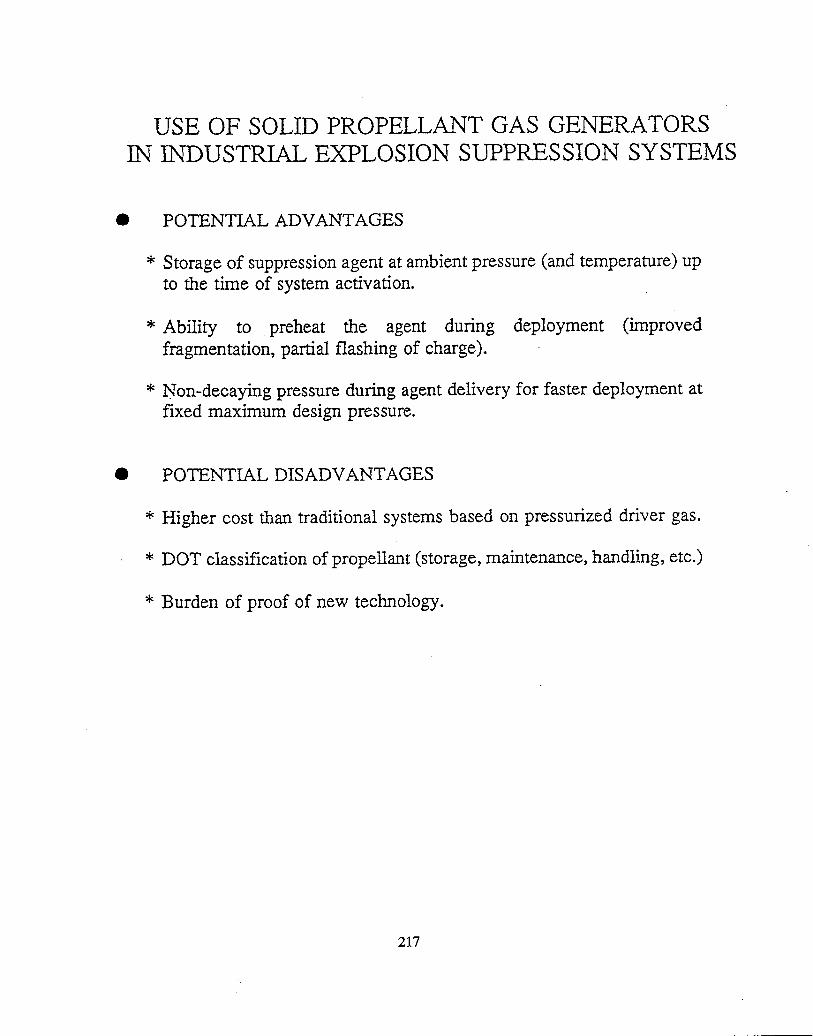
IN
●
*
*
*
●
*
*
*
USEOF SOLIDPROPELLANTGAS GENERATORSINDUSTRIALEXPLOSIONSUPPRESSIONSYSTEMS
POTENTIAL ADVANTAGES
Storage of suppression agent at ambient pressure (and temperature) upto the time of system activation.
Ability to preheat the agent during deployment (improvedfragmentation, partial flashing of charge).
Non-decaying pressure during agent delivery for faster deployment atfixed maximum design pressure.
POTENTIAL DISADVANTAGES
Higher cost than traditional systems based on pressurized driver gas.
DOT classification of propellant (storage, maintenance, handling, etc.)
Burden of proof of new technology.
217

PAGE 1 OF 2
11S1-114 U.S. DEPARTMENT OF COMMERCE ;“ ““’:’””””’”““ .2[kR*psE’oNLY)’::‘:”” ‘“‘;.REV. 6-93) NATIONAL INSTITUTE OF STANDARC% AND TECHNOLOGY y:~o?F?~Jy~=R” ~“ “, ‘%y!’: :: “ .,iDMAN 4.09
PUiLICk~lm”*WORT.:NUM#R;.MANUSCRIPT REVIEW AND APPROVAL ,: . ~~NM!IR.::5T66“i.“““““”;
USTRUCTIONS: ATTACH ORIGINAL OF THIS FORM TO ONE (1) COPY OF MANUSCRIPT AND SEND TO Pu8~lc~Tlo*w~%; ::j ‘ NVM~R Pm~E~%!X~ :
“HE SECRETARY, APPROPRIATE EOITORIAL REVIEW BOARD “: ikii&ilii& :193’5 ~ “.’ ‘“ .“” .’” “ “.”’? .’::
“ITLE ANO SUBTITLE (CITE IN FULL)
iolid Propellant Gas Generators: Proceedings of the 1995 Workshop
:ONTRACT OR GRANT NUMBER TYPE OF REPORT AND/OR PERIOD COVERED
1WTHOR(S) (LAST NAME, FIRST INITIAL, SECOND INITIAL) PERFORMING ORGANIZATION (CHECK (X) ONE BOX)
x NISTIGAITHERSBURG
tang, Jiann C. and Grosshandler, William L., Editors NISTIBOULDER
JiLA/BOULDER
ABORATORY AND DIVISION NAMES (FIRST NIST AUTHOR ONLY)
luilding and Fire ResearchLaboratory,Fire ScienceDivision;PONSORING ORGANIZATION NAME AND COMPLETS ADDRESS (STREET, CITY, STATE, ZIP)
‘ROPOSED FOR NIST PUBLICATION
JOURNAL OF RESEARCH (NIST JRES) MONOGRAPH (NIST MN) LETTSR CIRCULAR
J. PHYS. & CHEM. REF. DATA (JPCRD) NATL. STD. REF. DATA SERIES (NIST NSRDS) BUILDING SCIENCE SERIES
HANDBOOK (NIST HB) FEDERAL INF. PROCESS. STOS. (NK3T FIPS) PRODUCT STANDARDS
SPECIAL PUBLICATION (NIST SP) LIST OF PUBLICATIONS (NIST LP) OTHER
TECHNICAL NOTE (NIST TN) x NIST iNTERAGENCY/lNTERNAL REPORT (NISTIR)
‘ROPOSED FOR NON-NIST PUBLICATION (CITE FULLY) Us. FOREIGN PUBLISHING MEDIUM
~ PAPER m CD-ROM
DISKEITS (SPECIFY)
OTHER (SPECIFY)
SUPPLEMENTARYNOTES
IBSTRACT (A 2000-CHARACTER OR LESS FACTUAL SUMMARY OF MOST SIGNIFICANT INFORMATION. IF OOCUMENT INCLUDES A SIGNIFICANT BIBLIOGRAPHY 01ITERATURE SURVEY, CITE IT HERE. SPELL OUT ACRONYMS ON FIRST REFERENCE.) (CONTINUE ON SEPARATE PAGE, IF NECESSARY.)
A workshopon solid propellantgas generatorswas held on June 28-29, 1995at the NationalInstituteof Standardsand Technolog!mderthe sponsorshipof the Buildingand Fire ResearchLaboratory. Gas generatortechnologywas first proposedas alternativet{don 1301(CF~Br)for in-flight fire protection. Becausethe technologyis still in a developingstage as a fire suppressionmethodhere is no standardtest apparatusfor evaluatingthe performanceof gas generators, and there remain many unansweredtechnicspestions for the potential users. The specific objectivesof the workshopwere (1) to identi~ certificationprocedures, (2) t!leterminewhichcritical parameterswere requiredto characterizethe performanceof a gas generator, (3) to developa standardtesnethodfor gas generatorevaluation, (4) to identifyother potentialapplications,and (5) to searchfor next generationof propellantslle participantsat the workshopincludedrepresentativesfrom aircraftand airframemanufacturingindustries, airbag and propellmmanufacturers,fire fighting equipment companies, military services, governmentagencies, and universities. The agenda of thvorkshopencompassedeleven presentationson varioustopics relevant to the applicationsof gas generatorsas a fire fighting toolollowed by several discussion sessions. Various important issues related to the achievementof the objectives set forth wenuklressed,and recommendationsregardingwhat role NISTshouldplay in thk new technologywere suggested.
[EY WORDS (MAXIMUM OF 9; 2B CHARACTERS AND SPACES EACH; SEPARATE WITH SEMICOLONS; ALPHABETIC ORDER; CAPITALIZE ONLY PROPER NAMES)
?ireResearch;Fire Suppression;Halons; Propellants;PropellantCombustion;Test Methods
AVAILABILITY NOTE TO AUTHOR(S): IF YOU DO NOT WISH THIS
& UNLIMITED m FOR OFFICIAL DISTRIBUTION - DO NOT RELEASE TO NTIS MANUSCRIPT ANNOUNCED BEFORE PUBLICATION,
ORDER FROM SUPERINTENDENT OF DOCUMENTS, U.S. GPO, WASHINGTON, DC 20402 PLEASE CHECK HERE.n
x ORDER FROM NTIS, SPRINGFIELD, VA 22161
WORDPERFECT