solid state relays 1-phase, proportional switching ... · potentiometer is possible. switching...
TRANSCRIPT
Solid state relayNumber of polesType of switchingRated operational voltageControl inputRated operational currentConfiguration layoutExternal supply
Specifications are subject to change without notice (22.11.2016) 1
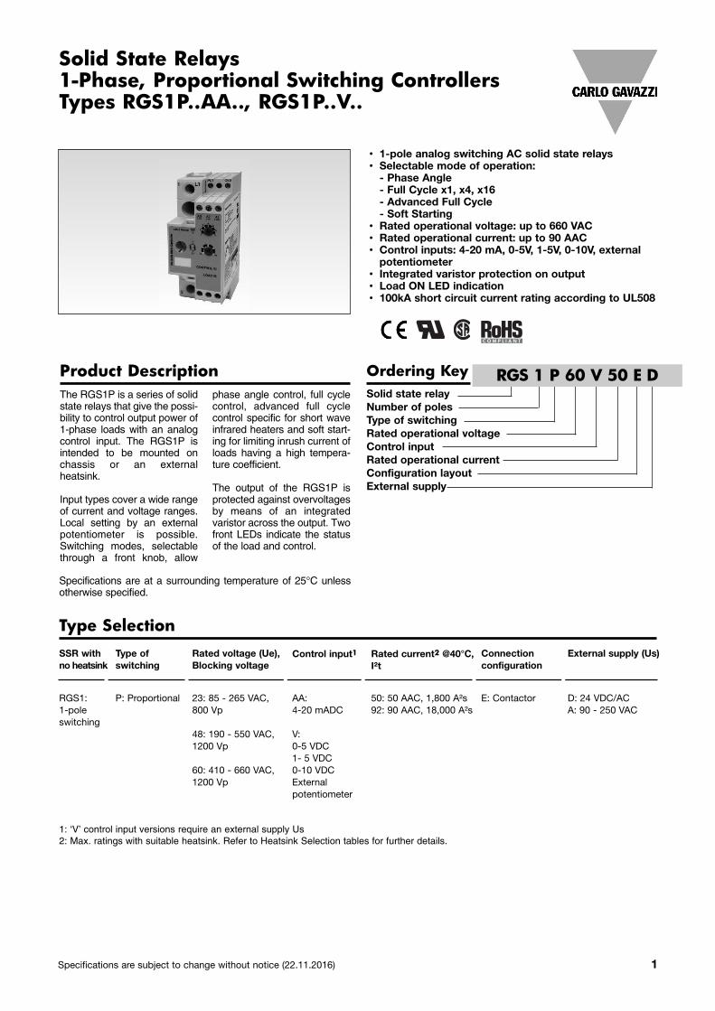
Product Description Ordering KeyThe RGS1P is a series of solidstate relays that give the possi-bility to control output power of1-phase loads with an analogcontrol input. The RGS1P isintended to be mounted onchassis or an externalheatsink.
Input types cover a wide rangeof current and voltage ranges.Local setting by an externalpotentiometer is possible.Switching modes, selectablethrough a front knob, allow
phase angle control, full cyclecontrol, advanced full cyclecontrol specific for short waveinfrared heaters and soft start-ing for limiting inrush current ofloads having a high tempera-ture coefficient.
The output of the RGS1P isprotected against overvoltagesby means of an integratedvaristor across the output. Twofront LEDs indicate the statusof the load and control.
Solid State Relays1-Phase, Proportional Switching Controllers Types RGS1P..AA.., RGS1P..V..
RGS 1 P 60 V 50 E D
Specifications are at a surrounding temperature of 25°C unlessotherwise specified.
1: ‘V’ control input versions require an external supply Us2: Max. ratings with suitable heatsink. Refer to Heatsink Selection tables for further details.
Type Selection
• 1-pole analog switching AC solid state relays• Selectable mode of operation:- Phase Angle- Full Cycle x1, x4, x16- Advanced Full Cycle- Soft Starting
• Rated operational voltage: up to 660 VAC• Rated operational current: up to 90 AAC• Control inputs: 4-20 mA, 0-5V, 1-5V, 0-10V, externalpotentiometer
• Integrated varistor protection on output• Load ON LED indication• 100kA short circuit current rating according to UL508
SSR withno heatsink
Type of switching
Rated voltage (Ue),Blocking voltage
Control input1 Rated current2 @40°C,I²t
Connection configuration
External supply (Us)
RGS1: 1-poleswitching
P: Proportional 23: 85 - 265 VAC, 800 Vp
48: 190 - 550 VAC,1200 Vp
60: 410 - 660 VAC,1200 Vp
AA:4-20 mADC
V:0-5 VDC1- 5 VDC0-10 VDCExternal potentiometer
50: 50 AAC, 1,800 A²s92: 90 AAC, 18,000 A²s
E: Contactor D: 24 VDC/ACA: 90 - 250 VAC
2 Specifications are subject to change without notice (22.11.2016)
Selection Guide
RGS1P..AA, RGS1P..V
General Specifications
RGS1P..AA RGS1P..V
Operational frequency range 45 to 65 Hz 45 to 65 Hz
Power factor > 0.7 @ rated voltage > 0.7 @ rated voltageTouch Protection IP20 IP20LED status indication3
Green Control input Control input<4 mA, flashing 0.5s ON, 0.5s OFF <0 V, flashing 0.5s ON, 0.5s OFF>4 mA, intensity varies with input >0 V, fully ONSupply ON (Us) Supply ON (Us)n/a Flashing 0.5s ON, 0.5s OFF
Yellow Load ON Load ON
Pollution degree 2 (non-conductive pollution with 2 (non-conductive pollution with possibilities of condensation) possibilities of condensation)
Over-voltage category III (fixed installations) III (fixed installations)Isolation L1, T1, A1, A2, A3, POT, GND, Us to case 4000 Vrms 4000 Vrms
L1, T1 to A1, A2, A3, Pot, GND, Us 2500 Vrms 2500 Vrms
Us to A1, A2, A3, POT, GND n/a n/a (..V..ED)1500 Vrms (..V..EA)
3: Refer to LED Indications section
Output voltage, Ue
Control input
External supply, Us
Power connection Rated operational current (I²t value)Product width
50 AAC(1,800 A²s)35 mm
90 AAC(18,000 A²s)35 mm
85 - 265 VAC AA: - Screw RGS1P23AA50E -
4-20 mADC Box - RGS1P23AA92E
V: 24 VDC/AC Screw RGS1P23V50ED -
0-10V, 0-5V, 1-5VDC, pot Box - RGS1P23V92ED
90-250 VAC Screw RGS1P23V50EA -
Box - RGS1P23V92EA
190 - 550 VAC AA: - Screw RGS1P48AA50E -
4-20 mADC Box - RGS1P48AA92E
V: 24 VDC/AC Screw RGS1P48V50ED -
0-10V, 0-5V, 1-5VDC, pot Box - RGS1P48V92ED
90-250 VAC Screw RGS1P48V50EA -
Box - RGS1P48V92EA
410 - 660 VAC AA: - Screw RGS1P60AA50E -
4-20 mADC Box - RGS1P60AA92E
V: 24 VDC/AC Screw RGS1P60V50ED -
0-10V, 0-5V, 1-5VDC, pot Box - RGS1P60V92ED
90-250 VAC Screw RGS1P60V50EA -
Box - RGS1P60V92EA
Specifications are subject to change without notice (22.11.2016) 3
RGS1P..AA, RGS1P..V
Output Voltage Specifications
RGS1P23.. RGS1P48.. RGS1P60..
Operational voltage range (Ue) 85-265 VAC 190-550 VAC 410-660 VACBlocking voltage 800 Vp 1200 Vp 1200 VpLeakage current @ rated voltage ≤ 5 mAAC ≤ 5 mAAC ≤ 5 mAAC Internal Varistor across output Yes Yes Yes
Output SpecificationsRGS1P..50 RGS1P..92
Rated operational current per pole4AC-51 50 AAC 90 AACAC-55b5 50 AAC 90 AACMinimum operational current 250 mAAC 500 mAACRep. Overload Current PF = 0.7UL508: T=40°C, tON=1s, tOFF=9s, 50cycles 107 AAC 168 AACMaximum transient surge current (Itsm), t=10ms 600 Ap 1900 ApI²t for fusing (t=10ms), minimum 1800 A²s 18000 A²sCritical dv/dt (@ Tj init = 40°C) 1000 V/us 1000 V/us
4: Max. current with suitable heatsink. Refer to Heatsink Selection tables.5: Overload profile for AC-55b, Ie: AC-55b: 6x Ie - 0.2: 50 - x; where Ie = nominal current (AAC), 0.2 is the duration of the overload (6xIe) in seconds, 50 is the duty cycle in %, and x = no. of starts. RGS1P..50: AC-55b: 180 - 0.2 : 50 - 15; RGS1P..92: AC-55b: 300 - 0.2 : 50 - 350. Consult Carlo Gavazzi representative for other overload current values.
Supply Specifications
RGS1P..V..D RGS1P..V..A
Supply voltage range (Us)6 24 VDC, -15% / +20% 90-250 VAC24 VAC, -15% / +15% -
Overvoltage protection up to 32 VDC/AC for 30 sec. n/a
Reverse Protection Yes n/a
Surge Protection7 Yes, integrated Yes, integratedMax. supply current 30 mA 14 mA
6. 24 DC / AC to be supplied from a Class 2 power source7. Refer to Electromagnetic Compatibility section
RGS1P..AA, RGS1P..V
4 Specifications are subject to change without notice (22.11.2016)
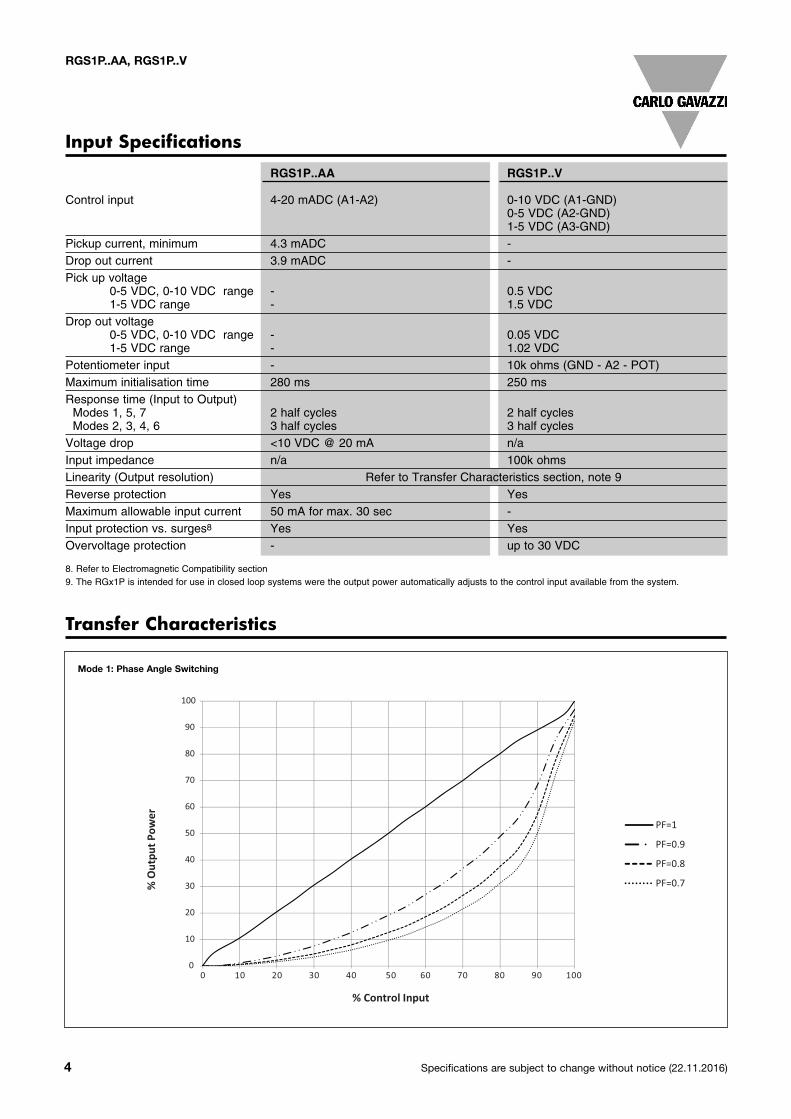
Transfer Characteristics
Input Specifications
RGS1P..AA RGS1P..V
Control input 4-20 mADC (A1-A2) 0-10 VDC (A1-GND)0-5 VDC (A2-GND)1-5 VDC (A3-GND)
Pickup current, minimum 4.3 mADC -Drop out current 3.9 mADC -Pick up voltage
0-5 VDC, 0-10 VDC range - 0.5 VDC1-5 VDC range - 1.5 VDC
Drop out voltage0-5 VDC, 0-10 VDC range - 0.05 VDC1-5 VDC range - 1.02 VDC
Potentiometer input - 10k ohms (GND - A2 - POT)Maximum initialisation time 280 ms 250 msResponse time (Input to Output)Modes 1, 5, 7 2 half cycles 2 half cyclesModes 2, 3, 4, 6 3 half cycles 3 half cyclesVoltage drop <10 VDC @ 20 mA n/aInput impedance n/a 100k ohmsLinearity (Output resolution) Refer to Transfer Characteristics section, note 9Reverse protection Yes YesMaximum allowable input current 50 mA for max. 30 sec -Input protection vs. surges8 Yes YesOvervoltage protection - up to 30 VDC
8. Refer to Electromagnetic Compatibility section9. The RGx1P is intended for use in closed loop systems were the output power automatically adjusts to the control input available from the system.
% O
utpu
t Pow
er
% Control Input
0
10
20
30
40
50
60
70
80
90
100
0 10 20 30 40 50 60 70 80 90 100
PF=1
PF=0.9
PF=0.8
PF=0.7
Mode 1: Phase Angle Switching
Specifications are subject to change without notice (22.11.2016) 5
RGS1P..AA, RGS1P..V
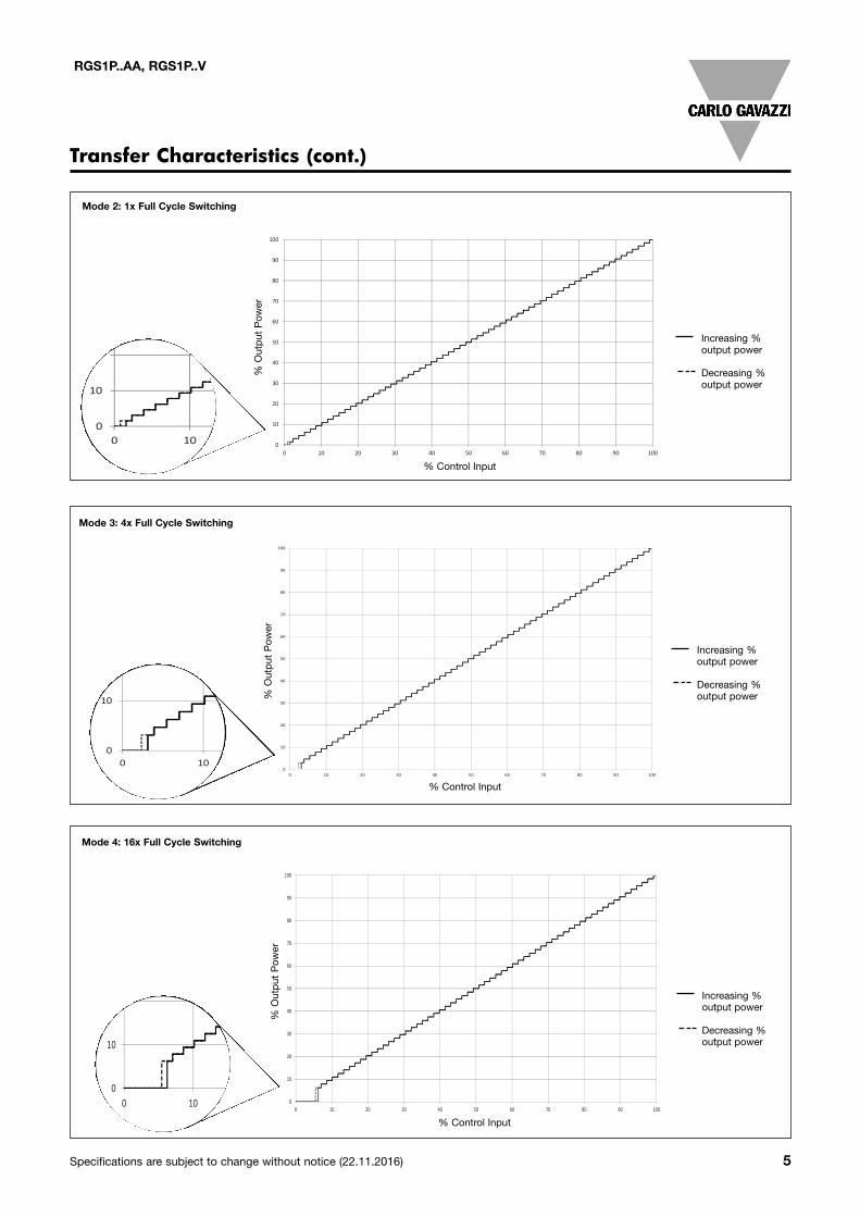
Transfer Characteristics (cont.)
0
10
20
30
40
50
60
70
80
90
100
0 10 20 30 40 50 60 70 80 90 100
% O
utpu
t Pow
er
% Control Input
%OutputGoing Down
%OutputGoing Up
0
10
20
30
40
50
60
70
80
90
100
0 10 20 30 40 50 60 70 80 90 100
% Ou
tput
Powe
r
% Control Input
%OutputGoing Up
%OutputGoing Down
0
10
20
30
40
50
60
70
80
90
100
0 10 20 30 40 50 60 70 80 90 100
% O
utp
ut
Po
we
r
% Control Input
%OutputGoing Up
%OutputGoing Down
Mode 2: 1x Full Cycle Switching
Mode 3: 4x Full Cycle Switching
Mode 4: 16x Full Cycle Switching
Increasing %output power
Decreasing %output power
Increasing %output power
Decreasing %output power
Increasing %output power
Decreasing %output power
% Control Input
% Control Input
% Control Input
% Output Pow
er% Output Pow
er% Output Pow
er
0
10
0 10 20 30 40 50 60 70 80 90 100
%
0
10
2
0 10 20 30 40 50 60 70 80 90 100
%
0
10
20
3
0 10 20 30 40 50 60 70 80 90 100
%
6 Specifications are subject to change without notice (22.11.2016)
RGS1P..AA, RGS1P..V
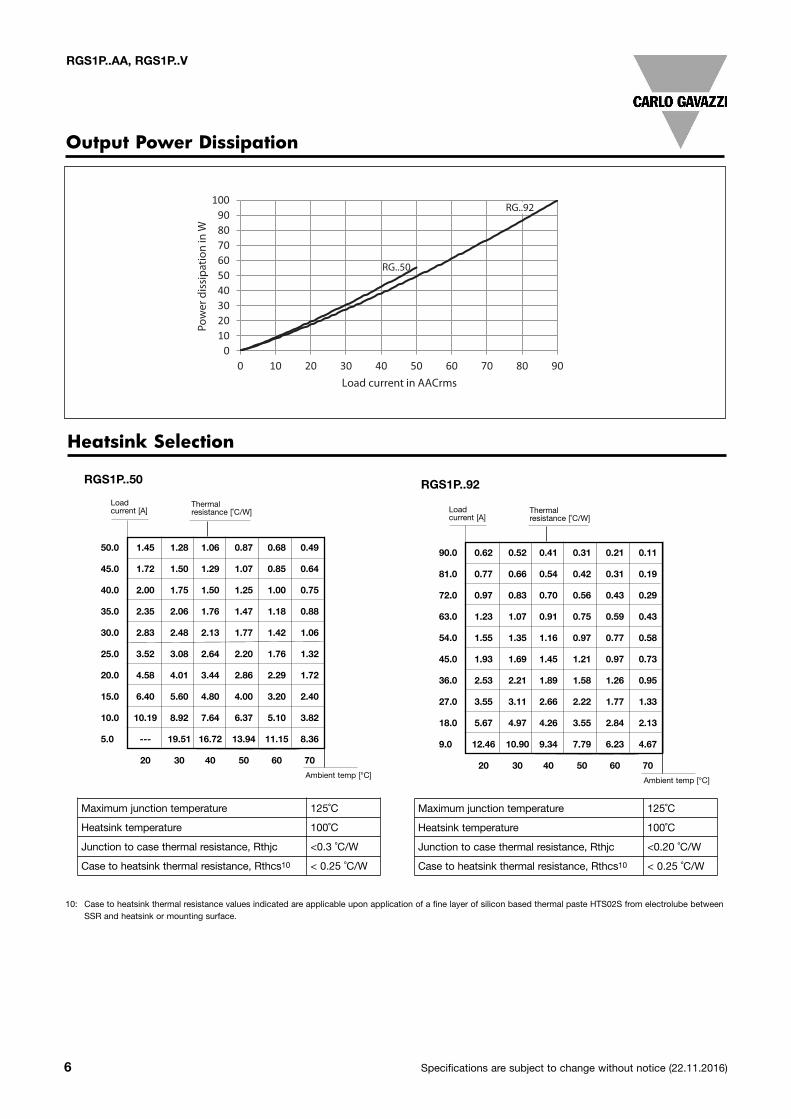
Output Power Dissipation
0102030405060708090
100
0 10 20 30 40 50 60 70 80 90
Pow
er d
issi
patio
n in
W
Load current in AACrms
RG..50
RG..92
Heatsink Selection
50.0 1.45 1.28 1.06 0.87 0.68 0.49
45.0 1.72 1.50 1.29 1.07 0.85 0.64
40.0 2.00 1.75 1.50 1.25 1.00 0.75
35.0 2.35 2.06 1.76 1.47 1.18 0.88
30.0 2.83 2.48 2.13 1.77 1.42 1.06
25.0 3.52 3.08 2.64 2.20 1.76 1.32
20.0 4.58 4.01 3.44 2.86 2.29 1.72
15.0 6.40 5.60 4.80 4.00 3.20 2.40
10.0 10.19 8.92 7.64 6.37 5.10 3.82
5.0 --- 19.51 16.72 13.94 11.15 8.36
20 30 40 50 60 70
RGS1P..50
Load current [A]
Thermal resistance [˚C/W]
Ambient temp [°C]
Maximum junction temperature 125˚C
Heatsink temperature 100˚C
Junction to case thermal resistance, Rthjc <0.3 ˚C/W
Case to heatsink thermal resistance, Rthcs10 < 0.25 ˚C/W
Maximum junction temperature 125˚C
Heatsink temperature 100˚C
Junction to case thermal resistance, Rthjc <0.20 ˚C/W
Case to heatsink thermal resistance, Rthcs10 < 0.25 ˚C/W
90.0 0.62 0.52 0.41 0.31 0.21 0.11
81.0 0.77 0.66 0.54 0.42 0.31 0.19
72.0 0.97 0.83 0.70 0.56 0.43 0.29
63.0 1.23 1.07 0.91 0.75 0.59 0.43
54.0 1.55 1.35 1.16 0.97 0.77 0.58
45.0 1.93 1.69 1.45 1.21 0.97 0.73
36.0 2.53 2.21 1.89 1.58 1.26 0.95
27.0 3.55 3.11 2.66 2.22 1.77 1.33
18.0 5.67 4.97 4.26 3.55 2.84 2.13
9.0 12.46 10.90 9.34 7.79 6.23 4.67
20 30 40 50 60 70
RGS1P..92
Load current [A]
Thermal resistance [˚C/W]
Ambient temp [°C]
10: Case to heatsink thermal resistance values indicated are applicable upon application of a fine layer of silicon based thermal paste HTS02S from electrolube between SSR and heatsink or mounting surface.
Specifications are subject to change without notice (22.11.2016) 7
RGS1P..AA, RGS1P..V
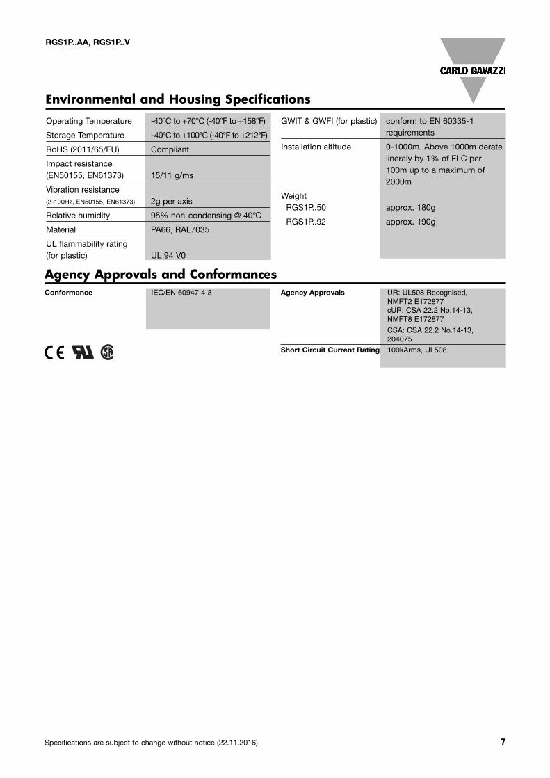
Operating Temperature -40°C to +70°C (-40°F to +158°F)
Storage Temperature -40°C to +100°C (-40°F to +212°F)
RoHS (2011/65/EU) Compliant
Impact resistance (EN50155, EN61373) 15/11 g/ms
Vibration resistance (2-100Hz, EN50155, EN61373) 2g per axis
Relative humidity 95% non-condensing @ 40°C
Material PA66, RAL7035
UL flammability rating (for plastic) UL 94 V0
GWIT & GWFI (for plastic) conform to EN 60335-1 requirements
Installation altitude 0-1000m. Above 1000m derate lineraly by 1% of FLC per 100m up to a maximum of 2000m
WeightRGS1P..50 approx. 180g
RGS1P..92 approx. 190g
Environmental and Housing Specifications
Conformance IEC/EN 60947-4-3
Agency Approvals UR: UL508 Recognised, NMFT2 E172877 cUR: CSA 22.2 No.14-13, NMFT8 E172877
CSA: CSA 22.2 No.14-13, 204075
Short Circuit Current Rating 100kArms, UL508
Agency Approvals and Conformances
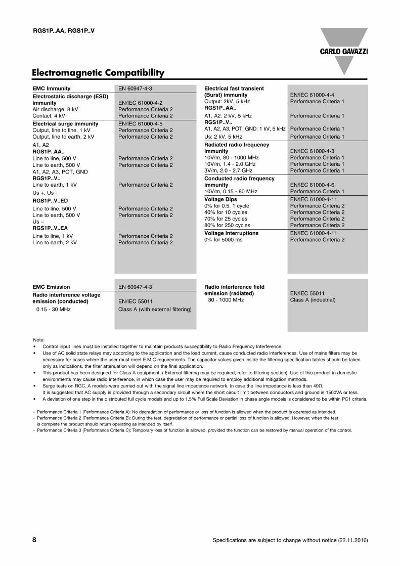
EMC Immunity EN 60947-4-3 Electrostatic discharge (ESD)immunity EN/IEC 61000-4-2 Air discharge, 8 kV Performance Criteria 2Contact, 4 kV Performance Criteria 2
Electrical surge immunity EN/IEC 61000-4-5 Output, line to line, 1 kV Performance Criteria 2Output, line to earth, 2 kV Performance Criteria 2
A1, A2RGS1P..AA.. Line to line, 500 V Performance Criteria 2Line to earth, 500 V Performance Criteria 2A1, A2, A3, POT, GNDRGS1P..V.. Line to earth, 1 kV Performance Criteria 2
Us +, Us -
RGS1P..V..ED Line to line, 500 V Performance Criteria 2Line to earth, 500 V Performance Criteria 2Us ~ RGS1P..V..EALine to line, 1 kV Performance Criteria 2Line to earth, 2 kV Performance Criteria 2
Electrical fast transient (Burst) immunity EN/IEC 61000-4-4 Output: 2kV, 5 kHz Performance Criteria 1RGS1P..AA.. A1, A2: 2 kV, 5 kHz Performance Criteria 1RGS1P..V.. A1, A2, A3, POT, GND: 1 kV, 5 kHz Performance Criteria 1
Us: 2 kV, 5 kHz Performance Criteria 1
Radiated radio frequency immunity EN/IEC 61000-4-3 10V/m, 80 - 1000 MHz Performance Criteria 110V/m, 1.4 - 2.0 GHz Performance Criteria 13V/m, 2.0 - 2.7 GHz Performance Criteria 1
Conducted radio frequency immunity EN/IEC 61000-4-6 10V/m, 0.15 - 80 MHz Performance Criteria 1
Voltage Dips EN/IEC 61000-4-11 0% for 0.5, 1 cycle Performance Criteria 240% for 10 cycles Performance Criteria 270% for 25 cycles Performance Criteria 280% for 250 cycles Performance Criteria 2
Voltage Interruptions EN/IEC 61000-4-11 0% for 5000 ms Performance Criteria 2
EMC Emission EN 60947-4-3 Radio interference voltage emission (conducted) EN/IEC 55011 0.15 - 30 MHz Class A (with external filtering)
Radio interference field emission (radiated) EN/IEC 55011 30 - 1000 MHz Class A (industrial)
Electromagnetic Compatibility
8 Specifications are subject to change without notice (22.11.2016)
RGS1P..AA, RGS1P..V
Note:• Control input lines must be installed together to maintain products susceptibility to Radio Frequency Interference.• Use of AC solid state relays may according to the application and the load current, cause conducted radio interferences. Use of mains filters may be
necessary for cases where the user must meet E.M.C requirements. The capacitor values given inside the filtering specification tables should be taken only as indications, the filter attenuation will depend on the final application.
• This product has been designed for Class A equipment. ( External filtering may be required, refer to filtering section). Use of this product in domestic environments may cause radio interference, in which case the user may be required to employ additional mitigation methods.
• Surge tests on RGC..A models were carried out with the signal line impedence network. In case the line impedance is less than 40Ω, it is suggested that AC supply is provided through a secondary circuit where the short circuit limit between conductors and ground is 1500VA or less.
• A deviation of one step in the distributed full cycle models and up to 1.5% Full Scale Deviation in phase angle models is considered to be within PC1 criteria.
- Performance Criteria 1 (Performance Criteria A): No degradation of performance or loss of function is allowed when the product is operated as intended.- Performance Criteria 2 (Performance Criteria B): During the test, degredation of performance or partial loss of function is allowed. However, when the test is complete the product should return operating as intended by itself.
- Performance Criteria 3 (Performance Criteria C): Temporary loss of function is allowed, provided the function can be restored by manual operation of the control.
Specifications are subject to change without notice (22.11.2016) 9
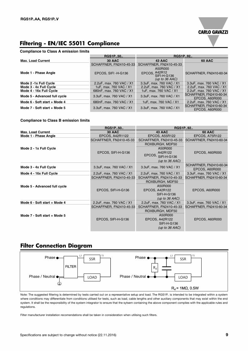
Filtering - EN/IEC 55011 ComplianceCompliance to Class A emission limits
Filter Connection Diagram
Note: The suggested filtering is determined by tests carried out on a representative setup and load. The RGS1P.. is intended to be integrated within a systemwhere conditions may differentiate from conditions utilised for tests, such as load, cable lengths and other auxiliary components that may exist within the endsystem. It shall be the responsibility of the system integrator to ensure that the sytsem containing the above component complies with the applicable rules andregulations.
Filter manufacturer installation recomendations shall be taken in consideration when utilising such filters.
RGS1P..50.. RGS1P..92..Max. Load Current 30 AAC 43 AAC 60 AAC
SCHAFFNER, FN2410-45-33 SCHAFFNER, FN2410-45-33
Mode 1 - Phase AngleA50R000
EPCOS, SIFI -H-G136 EPCOS, A42R12 SCHAFFNER, FN2410-60-34SIFI-H-G136(up to 36 AAC)
Mode 2 -1x Full Cycle 2.2uF, max. 760 VAC / X1 3.3uF, max. 760 VAC / X1 3.3uF, max. 760 VAC / X1 Mode 3 - 4x Full Cycle 1uF, max. 760 VAC / X1 2.2uF, max. 760 VAC / X1 2.2uF, max. 760 VAC / X1 Mode 4 - 16x Full Cycle 680nF, max. 760 VAC / X1 1uF, max. 760 VAC / X1 2.2uF, max. 760 VAC / X1
Mode 5 - Advanced full cycle 3.3uF, max. 760 VAC / X1 3.3uF, max. 760 VAC / X1 SCHAFFNER, FN2410-60-34EPCOS, A60R000
Mode 6 - Soft start + Mode 4 680nF, max. 760 VAC / X1 1uF, max. 760 VAC / X1 2.2uF, max. 760 VAC / X1
Mode 7 - Soft start + Mode 5 3.3uF, max. 760 VAC / X1 3.3uF, max. 760 VAC / X1SCHAFFNER, FN2410-60-34
EPCOS, A60R000
RGS1P..50.. RGS1P..92..Max. Load Current 30 AAC 43 AAC 60 AACMode 1 - Phase Angle EPCOS, A42R1122 EPCOS, A55R122 EPCOS, A75R122
SCHAFFNER, FN2410-45-33 SCHAFFNER, FN2410-45-33 SCHAFFNER, FN2410-60-34ROXBURGH, MDF50
Mode 2 - 1x Full Cycle A50R000EPCOS, SIFI-H-G136
EPCOS, A42R122 EPCOS, A60R000SIFI-H-G136(up to 36 AAC)
SCHAFFNER, FN2410-60-34Mode 3 - 4x Full Cycle 3.3uF, max. 760 VAC / X1 3.3uF, max. 760 VAC / X1
EPCOS, A60R000Mode 4 - 16x Full Cycle 2.2uF, max. 760 VAC / X1 2.2uF, max. 760 VAC / X1 3.3uF, max. 760 VAC / X1
SCHAFFNER, FN2410-45-33 SCHAFFNER, FN2410-45-33 SCHAFFNER, FN2410-60-34ROXBURGH, MDF50
Mode 5 - Advanced full cycle A50R000EPCOS, SIFI-H-G136 EPCOS, A42R122 EPCOS, A60R000
SIFI-H-G136 (up to 36 AAC)
Mode 6 - Soft start + Mode 4 2.2uF, max. 760 VAC / X1 2.2uF, max. 760 VAC / X1 3.3uF, max. 760 VAC / X1 SCHAFFNER, FN2410-45-33 SCHAFFNER, FN2410-45-33 SCHAFFNER, FN2410-60-34
ROXBURGH, MDF50 Mode 7 - Soft start + Mode 5 A50R000
EPCOS, SIFI-H-G136 EPCOS, A42R122 EPCOS, A60R000SIFI-H-G136 (up to 36 AAC)
Compliance to Class B emission limits
RGS1P..AA, RGS1P..V
L1 T1L1 T1
FILTER
Phase
Phase / Neutral
Phase
Phase / Neutral
10 Specifications are subject to change without notice (22.11.2016)
RGS1P..AA, RGS1P..V
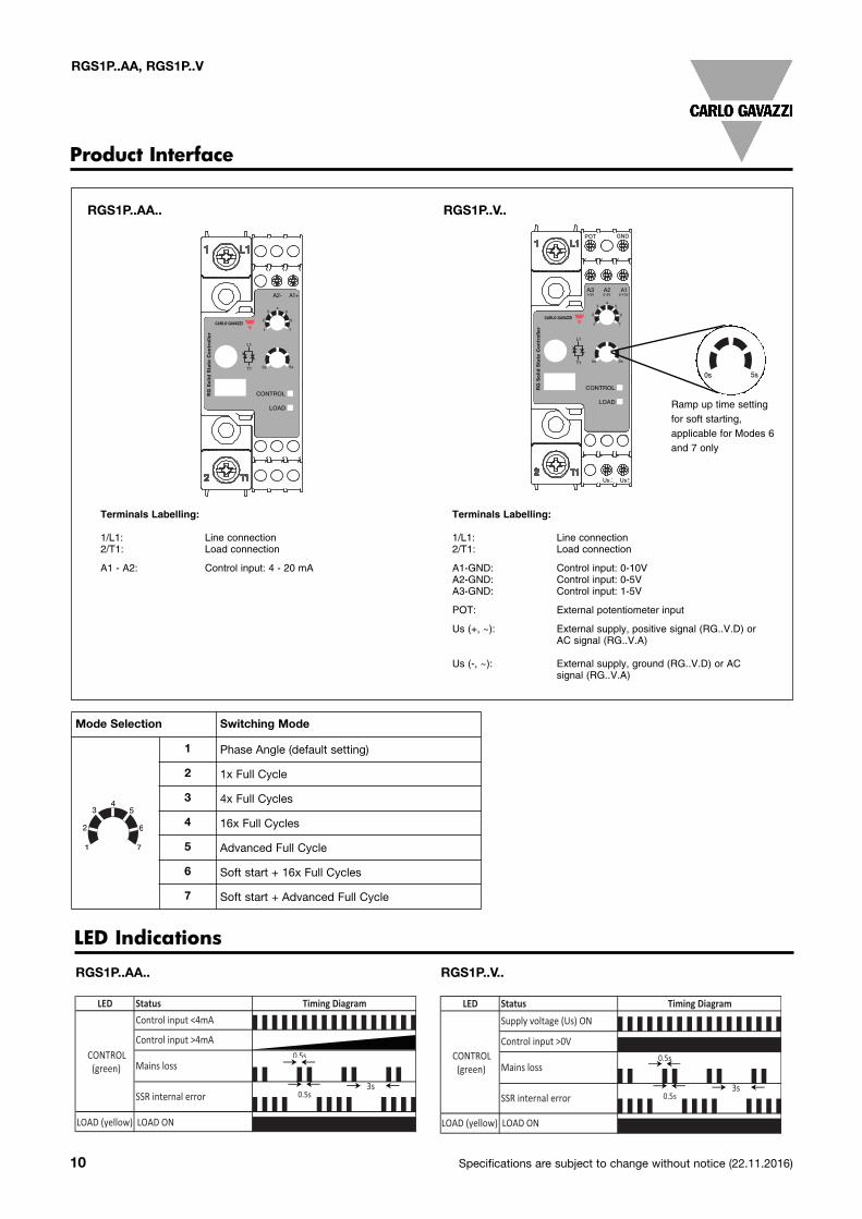
Product Interface
RGS1P..AA.. RGS1P..V..
Terminals Labelling:
1/L1: Line connection2/T1: Load connection
A1-GND: Control input: 0-10VA2-GND: Control input: 0-5V A3-GND: Control input: 1-5V
POT: External potentiometer input
Us (+, ~): External supply, positive signal (RG..V.D) or AC signal (RG..V.A)
Us (-, ~): External supply, ground (RG..V.D) or AC signal (RG..V.A)
Terminals Labelling:
1/L1: Line connection2/T1: Load connection
A1 - A2: Control input: 4 - 20 mA
Mode Selection Switching Mode
1 Phase Angle (default setting)
2 1x Full Cycle
3 4x Full Cycles
4 16x Full Cycles
5 Advanced Full Cycle
6 Soft start + 16x Full Cycles
7 Soft start + Advanced Full Cycle
LED Indications
RGS1P..AA.. RGS1P..V..
LED Status
RGC1P..AA
LED Status
RGC1P…VV
LED Status
RGC1P…K
Timing Diagram
Timing DiagramSupply voltage (Us) ON
Control input ON
Mains loss
SSR internal error
Mains loss
SSR internal error
Timing Diagram
Control input <4mA
Control input >4mA
CONTROL (green)
LOAD (yellow) LOAD ON
CONTROL (green)
LOAD (yellow) LOAD ON
CONTROL (green)
LOAD (yellow) LOAD ON
Supply voltage (Us) ON
Control input >0V
Mains loss
SSR internal error
0.5s
3s0.5s
0.5s
3s0.5s
0.5s
3s0.5s
LED Status
RGC1P..AA
LED Status
RGC1P…VV
LED Status
RGC1P…K
Timing Diagram
Timing DiagramSupply voltage (Us) ON
Control input ON
Mains loss
SSR internal error
Mains loss
SSR internal error
Timing Diagram
Control input <4mA
Control input >4mA
CONTROL (green)
LOAD (yellow) LOAD ON
CONTROL (green)
LOAD (yellow) LOAD ON
CONTROL (green)
LOAD (yellow) LOAD ON
Supply voltage (Us) ON
Control input >0V
Mains loss
SSR internal error
3s0.5s
0.5s
3s0.5s
0.5s
3s0.5s
Ramp up time setting for soft starting, applicable for Modes 6and 7 only
0s 5s
RG
Solid
Sta
te C
on
troller
CONTROL
LOAD
A2- A1+
54
3
62
1 7
0s 5sR
G S
olid
Sta
te C
ontr
olle
r
CONTROL
LOAD
A2
POT
Us Us+~
-~
GND
A1
54
3
62
1 7
A30-10V0-5V1-5V
0s 5s
RG
Solid
Sta
te C
on
troller
CONTROL
LOAD
A2- A1+
54
3
62
1 7
0s 5s
RG
Solid
Sta
te C
ontr
olle
r
CONTROL
LOAD
A2
POT
Us Us+~
-~
GND
A1
54
3
62
1 7
A30-10V0-5V1-5V
0s 5s
0s 5s
RG
Solid S
tate
Contr
oller
CONTROL
LOAD
Us Us+~
-~
GND
A1 24V
Specifications are subject to change without notice (22.11.2016) 11
RGS1P..AA, RGS1P..V
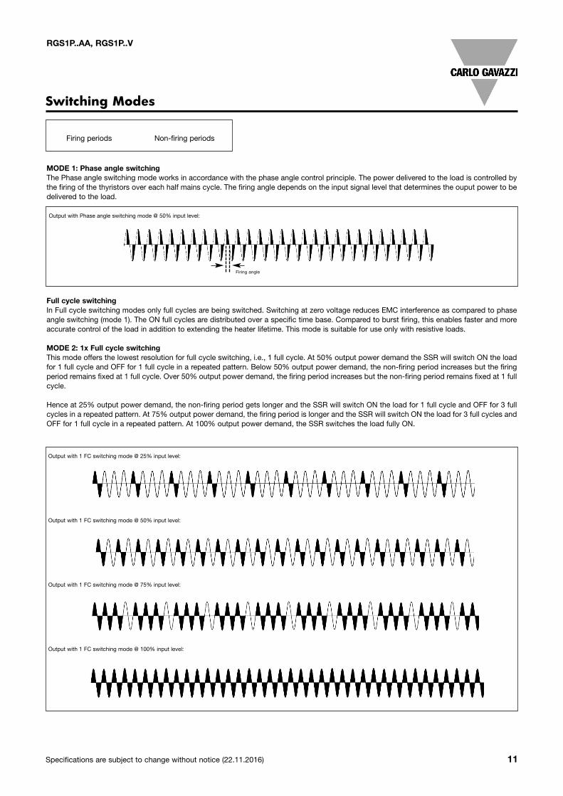
Firing angle
Switching Modes
MODE 1: Phase angle switchingThe Phase angle switching mode works in accordance with the phase angle control principle. The power delivered to the load is controlled bythe firing of the thyristors over each half mains cycle. The firing angle depends on the input signal level that determines the ouput power to bedelivered to the load.
Output with Phase angle switching mode @ 50% input level:
Full cycle switchingIn Full cycle switching modes only full cycles are being switched. Switching at zero voltage reduces EMC interference as compared to phaseangle switching (mode 1). The ON full cycles are distributed over a specific time base. Compared to burst firing, this enables faster and moreaccurate control of the load in addition to extending the heater lifetime. This mode is suitable for use only with resistive loads.
MODE 2: 1x Full cycle switchingThis mode offers the lowest resolution for full cycle switching, i.e., 1 full cycle. At 50% output power demand the SSR will switch ON the loadfor 1 full cycle and OFF for 1 full cycle in a repeated pattern. Below 50% output power demand, the non-firing period increases but the firingperiod remains fixed at 1 full cycle. Over 50% output power demand, the firing period increases but the non-firing period remains fixed at 1 fullcycle.
Hence at 25% output power demand, the non-firing period gets longer and the SSR will switch ON the load for 1 full cycle and OFF for 3 fullcycles in a repeated pattern. At 75% output power demand, the firing period is longer and the SSR will switch ON the load for 3 full cycles andOFF for 1 full cycle in a repeated pattern. At 100% output power demand, the SSR switches the load fully ON.
Output with 1 FC switching mode @ 25% input level:
Output with 1 FC switching mode @ 50% input level:
Output with 1 FC switching mode @ 75% input level:
Output with 1 FC switching mode @ 100% input level:
Firing periods Non-firing periods
12 Specifications are subject to change without notice (22.11.2016)
RGS1P..AA, RGS1P..V
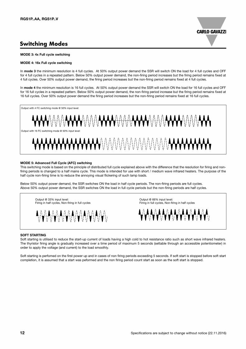
Switching Modes
MODE 5: Advanced Full Cycle (AFC) switching This switching mode is based on the principle of distributed full cycle explained above with the difference that the resolution for firing and non-firing periods is changed to a half mains cycle. This mode is intended for use with short / medium wave infrared heaters. The purpose of thehalf cycle non-firing time is to reduce the annoying visual flickering of such lamp loads.
Below 50% output power demand, the SSR switches ON the load in half cycle periods. The non-firing periods are full cycles. Above 50% output power demand, the SSR switches ON the load in full cycle periods but the non-firing periods are half cycles.
Output @ 33% input level: Output @ 66% input level:Firing in half cycles, Non-firing in full cycles Firing in full cycles, Non-firing in half cycles
SOFT STARTINGSoft starting is utilised to reduce the start-up current of loads having a high cold to hot resistance ratio such as short wave infrared heaters.The thyristor firing angle is gradually increased over a time period of maximum 5 seconds (settable through an accessible potentiometer) inorder to apply the voltage (and current) to the load smoothly.
Soft starting is perfomed on the first power up and in cases of non firing periods exceeding 5 seconds. If soft start is stopped before soft startcompletion, it is assumed that a start was peformed and the non firing period count start as soon as the soft start is stopped.
MODE 3: 4x Full cycle switching
MODE 4: 16x Full cycle switching
In mode 3 the minimum resolution is 4 full cycles. At 50% output power demand the SSR will switch ON the load for 4 full cycles and OFFfor 4 full cycles in a repeated pattern. Below 50% output power demand, the non-firing period increases but the firing period remains fixed at4 full cycles. Over 50% output power demand, the firing period increases but the non-firing period remains fixed at 4 full cycles.
In mode 4 the minimum resolution is 16 full cycles. At 50% output power demand the SSR will switch ON the load for 16 full cycles and OFFfor 16 full cycles in a repeated pattern. Below 50% output power demand, the non-firing period increase but the firing period remains fixed at16 full cycles. Over 50% output power demand the firing period increases but the non-firing period remains fixed at 16 full cycles.
Output with 4 FC switching mode @ 50% input level:
Output with 16 FC switching mode @ 50% input level:
Specifications are subject to change without notice (22.11.2016) 13
RGS1P..AA, RGS1P..V
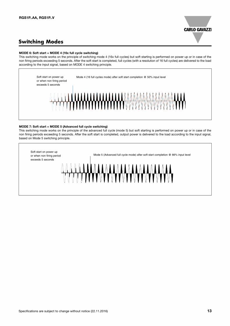
MODE 6: Soft start + MODE 4 (16x full cycle switching)This switching mode works on the principle of switching mode 4 (16x full cycles) but soft starting is performed on power up or in case of thenon firing periods exceeding 5 seconds. After the soft start is completed, full cycles (with a resolution of 16 full cycles) are delivered to the loadaccording to the input signal, based on MODE 4 switching principle.
MODE 7: Soft start + MODE 5 (Advanced full cycle switching)This switching mode works on the principle of the advanced full cycle (mode 5) but soft starting is performed on power up or in case of thenon firing periods exceeding 5 seconds. After the soft start is completed, output power is delivered to the load according to the input signal,based on Mode 5 switching principle.
Switching Modes
Soft start on power upor when non firing periodexceeds 5 seconds
Mode 4 (16 full cycles mode) after soft start completion @ 50% input level
Soft start on power up or when non firing period exceeds 5 seconds
Mode 5 (Advanced full cycle mode) after soft start completion @ 66% input level
14 Specifications are subject to change without notice (22.11.2016)
RGS1P..AA, RGS1P..V
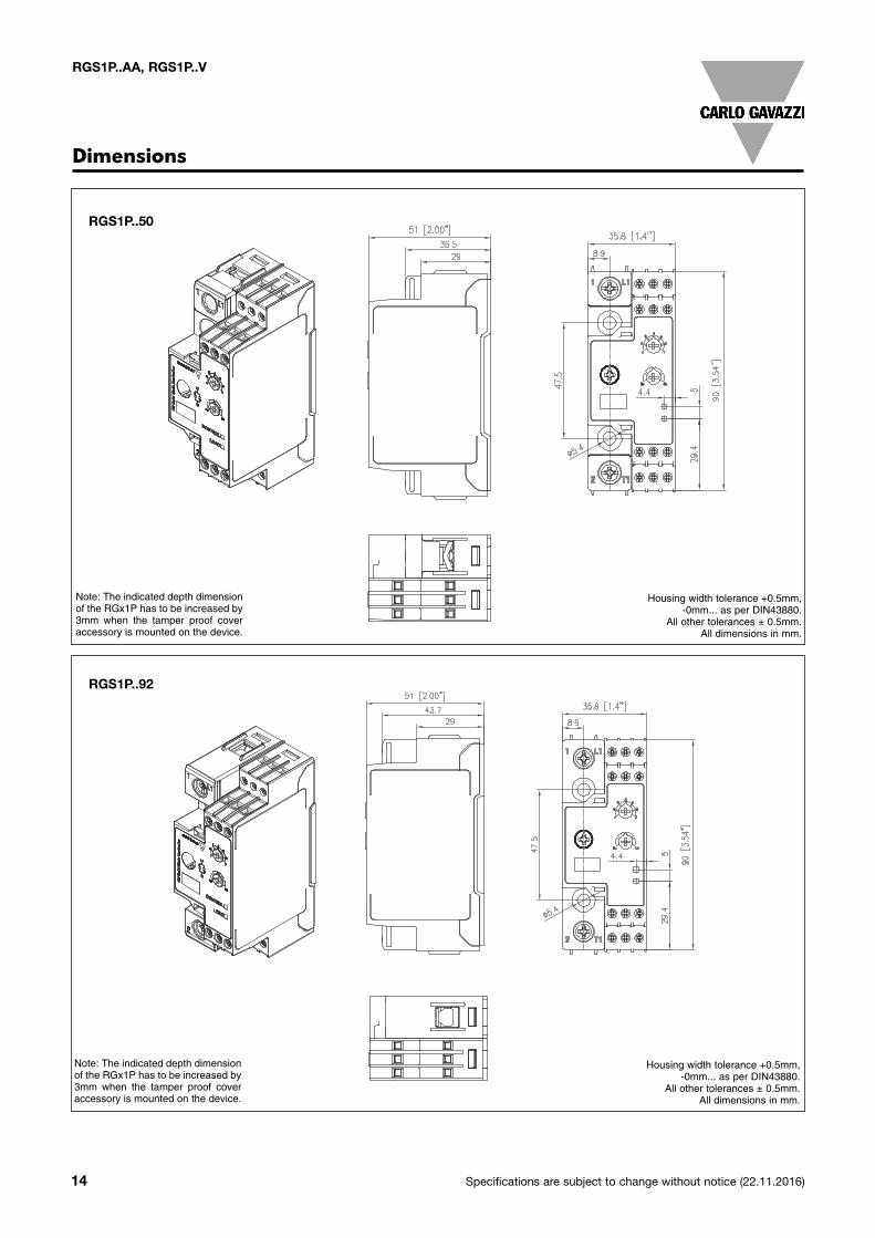
RGS1P..50
Dimensions
RGS1P..92
Housing width tolerance +0.5mm, -0mm... as per DIN43880.
All other tolerances ± 0.5mm.All dimensions in mm.
Note: The indicated depth dimensionof the RGx1P has to be increased by3mm when the tamper proof coveraccessory is mounted on the device.
Housing width tolerance +0.5mm, -0mm... as per DIN43880.
All other tolerances ± 0.5mm.All dimensions in mm.
Note: The indicated depth dimensionof the RGx1P has to be increased by3mm when the tamper proof coveraccessory is mounted on the device.
Specifications are subject to change without notice (22.11.2016) 15
RGS1P..AA, RGS1P..V
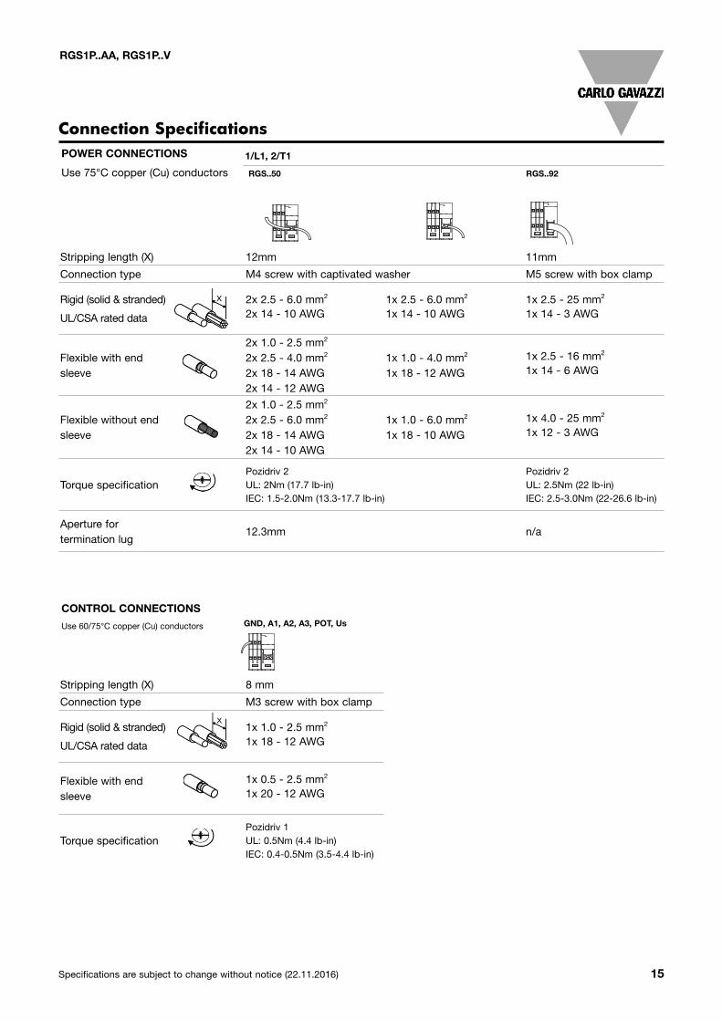
Stripping length (X) 8 mm
Connection type M3 screw with box clamp
Rigid (solid & stranded)
UL/CSA rated data
1x 1.0 - 2.5 mm2
1x 18 - 12 AWG
Flexible with endsleeve
1x 0.5 - 2.5 mm2
1x 20 - 12 AWG
Torque specificationPozidriv 1UL: 0.5Nm (4.4 lb-in)IEC: 0.4-0.5Nm (3.5-4.4 lb-in)
CONTROL CONNECTIONS
Use 60/75°C copper (Cu) conductors
Connection Specifications
Stripping length (X) 12mm 11mm
Connection type M4 screw with captivated washer M5 screw with box clamp
Rigid (solid & stranded)
UL/CSA rated data
2x 2.5 - 6.0 mm2
2x 14 - 10 AWG1x 2.5 - 6.0 mm2
1x 14 - 10 AWG1x 2.5 - 25 mm2
1x 14 - 3 AWG
Flexible with endsleeve
2x 1.0 - 2.5 mm2
2x 2.5 - 4.0 mm2
2x 18 - 14 AWG2x 14 - 12 AWG
1x 1.0 - 4.0 mm2
1x 18 - 12 AWG
1x 2.5 - 16 mm2
1x 14 - 6 AWG
Flexible without endsleeve
2x 1.0 - 2.5 mm2
2x 2.5 - 6.0 mm2
2x 18 - 14 AWG2x 14 - 10 AWG
1x 1.0 - 6.0 mm2
1x 18 - 10 AWG
1x 4.0 - 25 mm2
1x 12 - 3 AWG
Torque specificationPozidriv 2UL: 2Nm (17.7 lb-in)IEC: 1.5-2.0Nm (13.3-17.7 lb-in)
Pozidriv 2UL: 2.5Nm (22 lb-in)IEC: 2.5-3.0Nm (22-26.6 lb-in)
Aperture fortermination lug
12.3mm n/a
POWER CONNECTIONS
Use 75°C copper (Cu) conductors
1/L1, 2/T1
RGS..50 RGS..92
GND, A1, A2, A3, POT, Us
12, 30 12, 30 42,50,62 com12, 30 12, 30 42,50,62 com12, 30 12, 30 42,50,62 com
12, 30 12, 30 42,50,62 com
16 Specifications are subject to change without notice (22.11.2016)
RGS1P..AA, RGS1P..V
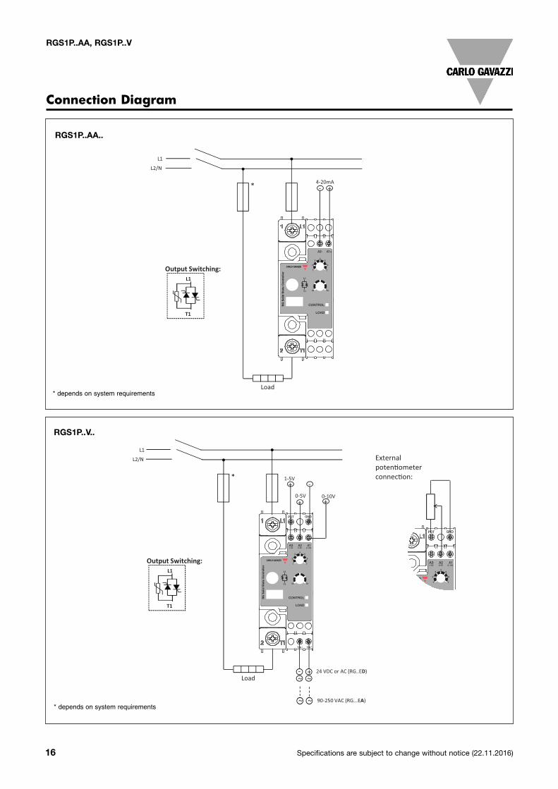
Connection Diagram
L1
L2/N
*
Load
L1
L2/N
*
Load- +
~ ~
24 VDC or AC (RG..ED)
90-250 VAC (RG...EA)
RG..AA..
RG..V..
External poten!ometerconnec!on:
Output Switching:L1
T1
Output Switching:L1
T1
~ ~
0s 5s
RG
Solid
Sta
te C
on
troller
CONTROL
LOAD
A2- A1+
54
3
62
1 7
0s 5s
RG
Solid
Sta
te C
on
trolle
r
CONTROL
LOAD
A2
POT
Us Us+~
-~
GND
A1
54
3
62
1 7
A30-10V0-5V1-5V
+-4-20mA
-
+0-10V+
+0-5V
1-5V
0s 5s
RG
Solid
Sta
te C
ontr
olle
r
CONTROL
LOAD
A2
POT
Us Us+~
-~
GND
A1
54
3
62
1 7
A30-10V0-5V1-5V
L1
L2/N
*
Load
L1
L2/N
*
Load- +
~ ~
24 VDC or AC (RG..ED)
90-250 VAC (RG...EA)
RG..AA..
RG..V..
External poten!ometerconnec!on:
Output Switching:L1
T1
Output Switching:L1
T1
~ ~
0s 5s
RG
Solid
Sta
te C
on
troller
CONTROL
LOAD
A2- A1+
54
3
62
1 7
0s 5s
RG
Solid
Sta
te C
on
trolle
r
CONTROL
LOAD
A2
POT
Us Us+~
-~
GND
A1
54
3
62
1 7
A30-10V0-5V1-5V
+-4-20mA
-
+0-10V+
+0-5V
1-5V
RGS1P..AA..
RGS1P..V..
* depends on system requirements
* depends on system requirements
Specifications are subject to change without notice (22.11.2016) 17
RGS1P..AA, RGS1P..V
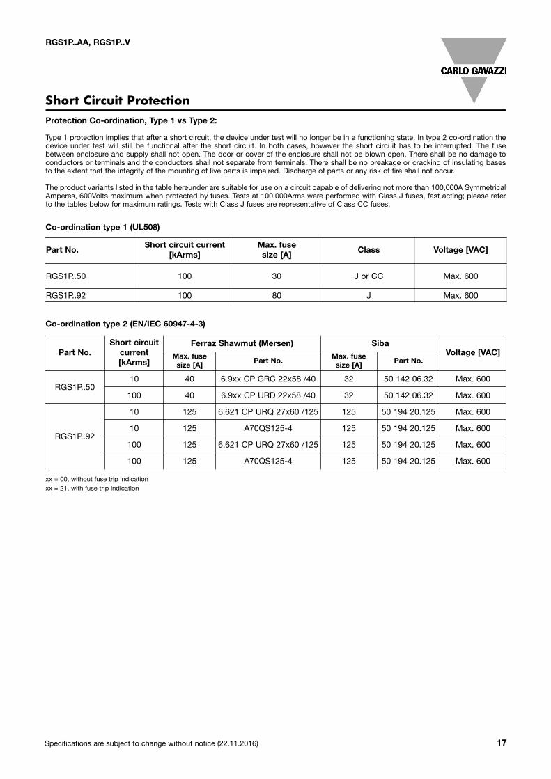
Protection Co-ordination, Type 1 vs Type 2:
Type 1 protection implies that after a short circuit, the device under test will no longer be in a functioning state. In type 2 co-ordination thedevice under test will still be functional after the short circuit. In both cases, however the short circuit has to be interrupted. The fusebetween enclosure and supply shall not open. The door or cover of the enclosure shall not be blown open. There shall be no damage toconductors or terminals and the conductors shall not separate from terminals. There shall be no breakage or cracking of insulating basesto the extent that the integrity of the mounting of live parts is impaired. Discharge of parts or any risk of fire shall not occur.
The product variants listed in the table hereunder are suitable for use on a circuit capable of delivering not more than 100,000A SymmetricalAmperes, 600Volts maximum when protected by fuses. Tests at 100,000Arms were performed with Class J fuses, fast acting; please referto the tables below for maximum ratings. Tests with Class J fuses are representative of Class CC fuses.
Short Circuit Protection
Part No.Short circuit current
[kArms]Max. fusesize [A]
Class Voltage [VAC]
RGS1P..50 100 30 J or CC Max. 600
RGS1P..92 100 80 J Max. 600
Co-ordination type 1 (UL508)
Co-ordination type 2 (EN/IEC 60947-4-3)
Part No.Short circuitcurrent[kArms]
Ferraz Shawmut (Mersen) SibaVoltage [VAC]Max. fuse
size [A]Part No.
Max. fusesize [A]
Part No.
RGS1P..5010 40 6.9xx CP GRC 22x58 /40 32 50 142 06.32 Max. 600
100 40 6.9xx CP URD 22x58 /40 32 50 142 06.32 Max. 600
RGS1P..92
10 125 6.621 CP URQ 27x60 /125 125 50 194 20.125 Max. 600
10 125 A70QS125-4 125 50 194 20.125 Max. 600
100 125 6.621 CP URQ 27x60 /125 125 50 194 20.125 Max. 600
100 125 A70QS125-4 125 50 194 20.125 Max. 600
xx = 00, without fuse trip indicationxx = 21, with fuse trip indication
18 Specifications are subject to change without notice (22.11.2016)
RGS1P..AA, RGS1P..V
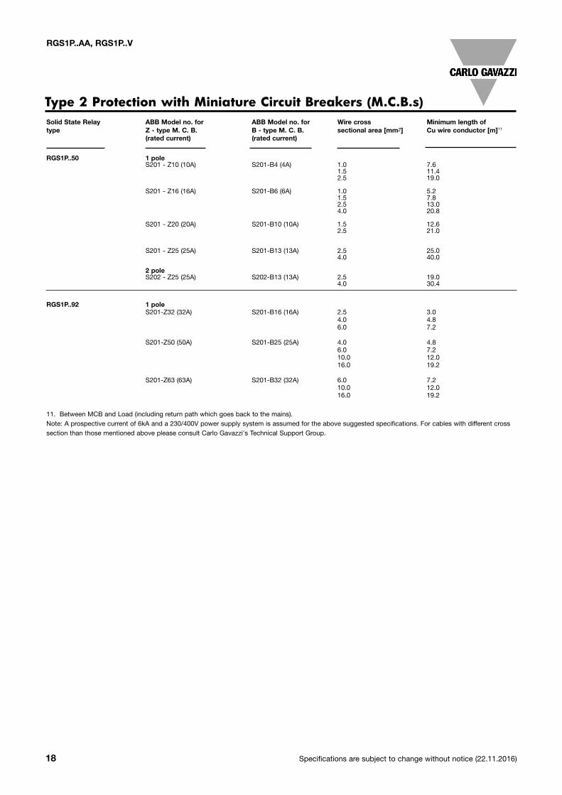
Type 2 Protection with Miniature Circuit Breakers (M.C.B.s)Solid State Relay ABB Model no. for ABB Model no. for Wire cross Minimum length oftype Z - type M. C. B. B - type M. C. B. sectional area [mm2] Cu wire conductor [m]11
(rated current) (rated current)
RGS1P..50 1 pole S201 - Z10 (10A) S201-B4 (4A) 1.0 7.6 1.5 11.4 2.5 19.0
S201 - Z16 (16A) S201-B6 (6A) 1.0 5.2 1.5 7.8 2.5 13.0 4.0 20.8 S201 - Z20 (20A) S201-B10 (10A) 1.5 12.6 2.5 21.0 S201 - Z25 (25A) S201-B13 (13A) 2.5 25.0 4.0 40.0 2 pole S202 - Z25 (25A) S202-B13 (13A) 2.5 19.0 4.0 30.4
RGS1P..92 1 pole S201-Z32 (32A) S201-B16 (16A) 2.5 3.0 4.0 4.8 6.0 7.2 S201-Z50 (50A) S201-B25 (25A) 4.0 4.8 6.0 7.2 10.0 12.0 16.0 19.2 S201-Z63 (63A) S201-B32 (32A) 6.0 7.2 10.0 12.0 16.0 19.2
11. Between MCB and Load (including return path which goes back to the mains).Note: A prospective current of 6kA and a 230/400V power supply system is assumed for the above suggested specifications. For cables with different crosssection than those mentioned above please consult Carlo Gavazzi's Technical Support Group.
Specifications are subject to change without notice (22.11.2016) 19
RGS1P..AA, RGS1P..V
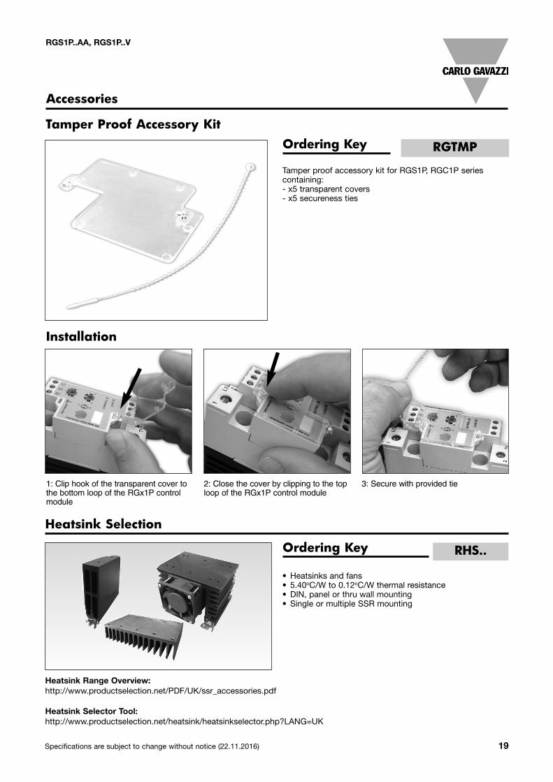
• Heatsinks and fans• 5.40oC/W to 0.12oC/W thermal resistance• DIN, panel or thru wall mounting• Single or multiple SSR mounting
Heatsink Selection
Tamper Proof Accessory Kit
Heatsink Range Overview:http://www.productselection.net/PDF/UK/ssr_accessories.pdf
Heatsink Selector Tool:http://www.productselection.net/heatsink/heatsinkselector.php?LANG=UK
Ordering Key RHS..
Accessories
Ordering Key
Tamper proof accessory kit for RGS1P, RGC1P series containing:- x5 transparent covers- x5 secureness ties
RGTMP
Installation
1: Clip hook of the transparent cover tothe bottom loop of the RGx1P controlmodule
2: Close the cover by clipping to the toploop of the RGx1P control module
3: Secure with provided tie

RGS1P..AA, RGS1P..V
Thermal Pads
- Graphite thermal pad for RG series with adhesive on one side- Width x Height x Thickness = 14 x 35 x 0.13 mm- Packing qty. 10 pcs.
Ordering Key RGHT
Thermal Paste
Screw Kits
- Silicone based thermal paste syringe- Volume = 2ml- Packing qty. 1 pc.
- RGS Screw kit for mounting to heatsink- Torx T20, size M5 x 30mm- Packing qty: 20pcs.
Ordering Key HTS02S
Ordering Key SRWKIT M5 X 30MM
20 Specifications are subject to change without notice (22.11.2016)