solid wood top kitchen cart with wood breakfast bar. gate leg 1 pc. r. t. brush chrome pipes 3 pcs....
TRANSCRIPT

Solid Wood Top Kitchen Cartwith Wood Breakfast Bar
PART LIST
IMPORTANT NOTECarefully remove all the parts from the carton and putthem individually on a soft cloth to prevent scratchesor other damages occuring to the parts.
We have taken great care in the design of thisproduct and request that you carefully and strictlyfollow our assembly instructions to ensure acompleted product as it was designed.
HARDWARE LIST
Hex Wrench1 pc.
Pull Handle2 pcs.
Machine Screwfor Pull Handle4 pcs.
Wood Screwfor Caster andGate Leg22 pcs. (+2 extra)
Wood Plug10 pcs.(+2 extra)
B.Side Panel
1 pc.
A.Top1 pc.
C.Side Panel1 pc.
F.Back Panel3 pcs.
G.Back Piece2 pcs.
H2.Front Piece1 pc.
H1.Front Piece
1 pc.
I.Back Stretcher1 pc.
J.Front Stretcher1 pc.
K.Front Rail3 pcs.
L.Base1 pc.
P.Shelf2 pcs.
Q.Side Rack
1 pc.
M.Gate Leg1 pc.
R.Side Rack1 pc.
T.Brush Chrome Pipes3 pcs.
E.MiddlePanel1 pc.
D.MiddlePanel1 pc.
S.Base Rack1 pc.(For Drawer N&O packed in separate
carton with hardware and assemblyinstructions.)
Castertwo locktwo non-lock4 pcs.
X.Door1 pc.
W.Door1 pc.
O.KD. Drawer1 pc.
N.KD. Drawer3 pcs.
Head Cap Bolt14 pcs. (+1 extra)
Adjustable Pin8 pcs. (+2 extra)
U.Handle Arm2 pcs.
V.Round Arm1 pc.
Cam Lock4 pcs.(+1 extra)
Cam Lock Screw4 pcs.(+1 extra)
Tools required for assembly : Phillips screwdriver
SmallHex Wrench1 pc.

Assembly Instructions 2/4
STEP 1
STEP 2
STEP 3
L
L
K
K
K
DE
B
Attach four Castersunderneath Base (L)with Wood Screws.(See ‘Arrow’ stickerindicating front side)
Assemble Front Piece (H1),(H2) and Front Rail (K).(See figure 1)
Attach
theside of unit with Head Cap Bolts.
the assembled unitto Middle Panel (D) and (E).
Attach Side Panel (B) to
Attach the Back Piece (G), Middle Panel (D)and Back Piece (G), Middle Panel (E) onto theBase (L).
GG
D E
H1
H2
Wood Screw
Wood Screw
Head Cap Bolt
Locking Caster(On Front)
(Figure 1)
IMPORTANT* Do not tighten up all the bolts until each part is properly assembled.* You should keep Hex Wrench in a safe place as you may need to tighten up the Head Cap Bolts in the future.* Use a soft cloth between these parts and the floor.
M
STEP 4
STEP 7
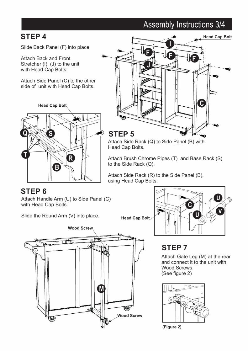
Slide Back Panel (F) into place.
Attach Back and FrontStretcher (I), (J) to the unitwith Head Cap Bolts.
Attach Side Panel (C) to the otherside of unit with Head Cap Bolts.
J
C
I
Attach Gate Leg (M) at the rearand connect it to the unit withWood Screws.(See figure 2)
FF F
B
R
S
T
Q STEP 5Attach Side Rack (Q) to Side Panel (B) withHead Cap Bolts.
Attach Brush Chrome Pipes (T) and Base Rack (S)to the Side Rack (Q).
Attach Side Rack (R) to the Side Panel (B),using Head Cap Bolts.
Head Cap Bolt
Head Cap Bolt
Wood Screw
Wood Screw
Head Cap Bolt
CV
U
USTEP 6Attach Handle Arm (U) to Side Panel (C)with Head Cap Bolts.
Slide the Round Arm (V) into place.
(Figure 2)
Assembly Instructions 3/4
STEP 8
STEP 9
STEP 10
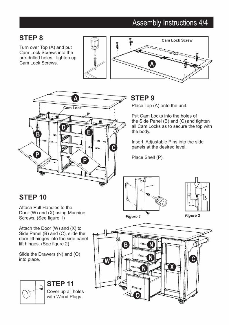
Place Top (A) onto the unit.
and tightenall Cam Locks as to secure the top withthe body.
Put Cam Locks into the holes ofthe Side Panel (B) and (C)
Insert Adjustable Pins into the sidepanels at the desired level.
Place Shelf (P).
A
P
WX
N
N
N
O
P
A
B
B
DE
C
C
Turn over Top (A) and putCam Lock Screws into thepre-drilled holes. Tighten upCam Lock Screws.
STEP 11Cover up all holeswith Wood Plugs.
Figure 1 Figure 2
Attach Pull Handles to theDoor (W) and (X) using MachineScrews. (See figure 1)
Attach the Door (W) and (X) toSide Panel (B) and (C), slide thedoor lift hinges into the side panellift hinges. (See figure 2)
Slide the Drawers (N) and (O)into place.
Cam Lock Screw
Cam Lock
Assembly Instructions 4/4

Assembly Instructions
N3.Side Part1 pc. for eachdrawer.
N4.Side Part
1 pc. for eachdrawer.
N5.Base Part1 pc. for eachdrawer.
N2.Back Part1 pc. for eachdrawer.
N2
N2
N5
N5
N3
N4
N4
N4
N3
N3
N1
N1
N1
Assemble the Pull Handlewith Machine Screw onthe Front Part (N1).
(Figure 1)
(Figure 2)
(Figure 3)
HARDWARE LIST
Pull Handle3 pcs.
Machine Screwfor Pull Handle6 pcs.
Wood Screw (short)for base part18 pcs.(+1 extra)
Wood Screw (long)for side part24 pcs.(+1 extra)
Insert the remaining (6) 1/2 screwsinto the pre-drilled holes on Base Part(N5), then tighten all screws.
”
make sure rolleris on the back
N1.Front Part1 pc. for eachdrawer.
N1
Slide the Plywood Base Part (N5) intothe grooves on Side Parts (N3) and (N4).Be sure to push the plywood all the wayforward so it meets the Front Part (N1).(See the figure 2)
Unfinished Side
UNIT PART LIST
Using a ,insert 1” screws into the pre-drilledholes as shown, tighten half way.(See the figure 1)
philips screwdriver
Drawer (N)

Assembly Instructions
O3.Side Part
1 pc. .
O5.Base Part1 pc.
O2.Back Part1 pc. .
O2
O2
O5
O5
O3
O4
O4
O4
O3
O3
O1
O1
O1
Assemble the Pull Handlewith Machine Screw onthe Front Part (O1).(See the figure 4)
(Figure 1)
(Figure 2)
(Figure 3)
(Figure 4)
HARDWARE LIST
Pull Handle1 pcs.
Machine Screwfor Pull Handle2 pcs.
Wood Screw (short)for base part6 pcs.(+1 extra)
Wood Screw (long)for side part8 pcs.(+1 extra)
Insert the remaining (6) 1/2 screwsinto the pre-drilled holes on Base Part(O5), then tighten all screws(See the figure 3)
”
make sure rolleris on the back
O1.Front Part1 pc.
Slide the Plywood Base Part (O5) intothe grooves on Side Parts (O3) and (O4).Be sure to push the plywood all the wayforward so it meets the Front Part (O1).(See the figure 2)
Unfinished Side
O4.Side Part1 pc.
O1
UNIT PART LIST
Using a , insert 1”screws into the pre-drilled holes as shown,tighten half way. (See the figure 1)
phillips screwdriver
Drawer (O)