solidification of an alloy from a cooled boundary
TRANSCRIPT

J . Fluid Mech. (1986). vol. 167, p p . 481-501
Printed in Great Britain 48 1
Solidification of an alloy from a cooled boundary
By M. GRAE WORSTERt Department of Mathematics, Massachusetts Institute of Technology, MA 02139, USA
(Received 16 October 1985)
We present a mathematical model for the region of dendritic or cellular growth which often forms during the solidification of alloys. The model treats the region of mixed phase (solid and liquid) as a continuum whose properties vary with the local volume fraction of solid. It is assumed that transports of heat and of solute are by diffusion alone, and the model is closed by a condition of marginal equilibrium. Results are obtained for the unidirectional solidification of an alloy from a plane wall. The spatial variations of solid fraction are highly suggestive of the types of morphology that can occur, and a wealth of different structures are found as the physical parameters are varied. Although the model ignores gravity entirely, the results can be applied to the solidification from below of an alloy which is initially less dense than its eutectic. Predictions for the growth rate of the mixed-phase region agree well with existing experimental measurements of ice growing from aqueous salt solutions.
1. Introduction Mathematical analyses of solidification are complicated by the need to apply
boundary conditions at solid/liquid interfaces which are evolving with time and whose positions must be found as part of the calculation. The case of a pure melt being cooled by conduction of heat to its boundaries is relatively straightforward since the geometry of the solidification front is similar to that of the bounding walls (Sekerka 1973). Such so-called ‘Stefan’ problems have been solved completely in some simple geometries. For example, solidification from a plane wall (Carslaw & Jaeger 1959 describe resultsattributed to Neumann in the 1860s), and the inward solidification of cylinders and spheres (Riley, Smith & Poots 1974; Soward 1980) have been considered. However, if a pure melt is supercooled (has a temperature below its freezing point), so that latent heat is conducted away from the solidification front through the liquid, then the solidification front becomes extremely convoluted and forms intricate branching patterns (Langer 1980). Snowflakes provide a common example of this phenomenon. When the liquid is an alloy (a mixture of two or more components) such behaviour is commonplace even when the liquid is not initially supercooled. The aim of this paper is to describe the solidification of an alloy in situations where the interface is highly convoluted.
A t present, analytical techniques cannot follow the evolution of such convolutions far beyond initial perturbations from a flat interface, though important results have been obtained recently through the use of high-speed computers (Ungar & Brown 1984), and boundary-layer models (Ben-Jacob et al. 1983). However, for many applications including metallurgy (Copley et al. 1970), solidification in magma chambers (Chen & Turner 1980; Turner, Huppert & Sparks 1986), and the structure
t Present address : Department of Applied Mathematics and Theoretical Physics, Silver Street, Cambridge, CB3 9EW, UK.

482 M . G . Worster
of the Earth’s inner core (Fearn, Loper & Roberts 1981 ; Loper 1983), it is the gross features of the solid-liquid matrix which forms as a result of the convolutions that are of more importance than the precise details of the microscopic morphology. The matrix, or region of mixed phase, has been termed a ‘ mush ’ or ‘mushy zone ’ by many previous authors who have investigated its behavioiir experimentally and analytically. By treating the mush as a new single phase, and the macroscopic envelope of the convoluted solid as a phase boundary, it is necessary to follow the evolution of two phase boundaries : the solid/mush interface and the mush/liquid interface. However, these new phase boundaries are geometrically simple, and hence mathematical tractability is restored.
Hills, Loper & Roberts (1983) developed a full set of thermodynamic equations for a mushy zone, and solved a much-reduced set of them approximately for the constrained growth of a binary alloy. A more complete solution has since been given by Fowler (1986). Constrained growth, in which the interfaces are supposed to advance at a prescribed constant velocity, is applicable to industrial crystal pulling (Czochralski growth), but not to the solidification of castings nor to many natural systems where growth can proceed at a rate inversely proportional to the square root of time.
Huppert & Worster (1985) formulated a simple mathematical model of the mushy layer based on considerations of global conservation relationships. Its predictions agreed well with their observations of ice growing at a plane boundary from aqueous solutions of various salts. The model is particularly easy to compute, and so may be of great practical use. However, it relies on various assumptions (particularly that the solid fraction is constant throughout the mush) whose limits of validity are difficult to assess.
In this paper, we present a subset of the equations derived by Hills et al. (1983), more general than the ones solved by Fowler (1986), and solve them for the unidirectional solidification of an alloy from a plane boundary. The equations conserve heat and solute locally but on a macroscale larger than the typical pore-size of the mush. Thus, unlike Huppert & Worster, we are able to ccmpute local bulk properties of the mush. In particular, we compute the local solid fraction as a function of distance from the cooled boundary, and this gives some indication of the morphology of the growing solid.
In $2 we describe the phase diagram for a two-component alloy which indicates the phases that are present in an alloy of given temperature and composition provided the system is in thermodynamic equilibrium. Although a certain amount of disequilibrium must exist in order to drive solidification, many systems evolve through states that are close to equilibrium, and good approximations may be obtained by assuming the system to be in a complete equilibrium at all times. Thus the phase diagram provides important constraints on our model of the dynamic evolution of a solidifying alloy. Phase diagrams are specific t o the components of the alloy, but the idealized diagram used in the development of our model is appropriate to many binary alloys - in particular, to almost all aqueous solutions.
The classical Stefan problem for the solidification of a pure melt from a plane boundary is extended in $3 to the case of a binary alloy. However, we discover in $4 that, when the flat interface advances too rapidly, constitutional supercooling occurs in the liquid. Local equilibrium is restored by the introduction of a mushy layer whose governing equations are introduced in $5. The equations and boundary conditions admit a similarity solution which is outlined in $6, and the model is finally closed by requiring a condition of marginal equilibrium a t the mush/liquid interface.

Solidi$cation of an alloy from a cooled boundary 483
/ \ / \ / \
1 CSA + CSB \ I \
I \
Composition .-+
FIQURE 1. (a) Typical equilibrium phase diagram for a binary system comprising two components A and B. The liquidus --, the solidus -, and the dashed line ----, separate the diagram into regions of different phases: L, liquid; CSA, a crystalline solid in which molecules of B are incorporated into the crystal lattice of A; CSB, a crystalline solid in which molecules of A are incorporated into the crystal lattice of B; CSA+CSB, a granular solid in which crystalline grains of CSA are interspersed with grains of CSB. The solidus and the liquidus intersect at the eutectic point E. (a) The approximate phase diagram used in the mathematical analyses.
Two sets of results are presented in $ 7 which give the positions of the two interfaces as they vary with the initial temperature and composition of the liquid and with the temperature of the cooled boundary. Selected profiles of solid fraction reveal significant variations in the possible morphology of the mushy layer as the external and internal parameters of the system are varied. The first set of results is for a fictitious alloy whose liquid and solid phases have equal physical properties. Since the number of independent parameters is thereby reduced, this system provides a convenient starting point for mathematical investigations. The second set of results applies directly to experiments of Huppert & Worster using aqueous solutions of sodium nitrate, so comparisons can be made between the present model, that of Huppert & Worster, and the experimental data.
2. The phase diagram Of central importance to the dynamics of solidification is the equilibrium. phase
diagram for the particular chemical system under consideration. We here describe a typical phase diagram for a system comprising two chemical components A and B (for example, water and salt).
The different regions of the phase diagram are labelled in figure l (a ) . Given a container filled with a mixture of bulk composition C (equal to the weight per cent of component B) it is in thermodynamic equilibrium only if the mixture has a uniform temperature, T (say). The coordinates (C, T) define a point on the phase diagram, and the region in which this point lies determines the phases present in the container once the system is in complete equilibrium. In the simple system considered here there is just one liquid phase but a number of solid phases. The crystalline solids (for example CSA) referred to in figure 1 (a) are solid solutions in which molecules of B are incorporated into the crystal lattice of A (vice versa for CSB). Note that the phase diagram says nothing about the spatial distribution of the phases, which is determined by the dynamical history of the system.

484 M . C. Worster
There are two important regional boundaries in the diagram : the liquidus curve, C = CL(T) or T = TL(C), that separates the region in which the system is completely liquid from that in which solid and liquid phases coexist; and the solidus curve, C = C,(T) or T = T,(C), that separates the latter region from the region in which the system is completely solid. Since physical systems tend to evolve towards equilibrium it is clear that if a completely liquid system has composition C and temperature T < TL(C) then i t will tend to solidify. Thus the liquidus curve represents the freezing temperature as a function of composition. Similarly, the solidus curve Ts(C) represents the temperature for the onset of partial melting of a solid.
An additional interpretation can be given to the solidus and liquidus curves. If a system is in equilibrium with (C, T ) in the mixed-phase region then, from our previous discussion, the solid part of the mixture must have composition Cs(T) while the liquid part must have composition CL(T). One of the major premises in this paper will be that during solidification the system is always close to equilibrium. Therefore, a t all solid/liquid interfaces the temperature is continuous with value T (say), while the composition jumps from CL(T) in the liquid to C,(T) in the solid.
The solidus and liquidus curves intersect when the system comprises a single component (A or B) and a t the eutectic point where C = C,. For systems with these special compositions there is a single melting/freezing temperature, and there is no concentration jump across solid/liquid interfaces.
The fluid dynamics of solidification in the presence of a gravity field depends crucially upon the variations in density of the liquid phase due to variations in its temperature and composition, and upon the geometry of the system (Chen & Turner 1980; Huppert & Worster 1985). Suppose that component B is heavier than component A so that increasing C causes the fluid density to increase. Suppose also (as is generally true) that the fluid density decreases with temperature a t constant composition. Huppert & Worster (1985) outline six different flow regimes that arise depending on whether the initial liquid concentration is less than, equal to, or greater than the eutectic composition C,, and whether the liquid is cooled from an upper or a lower horizontal boundary. In the present paper, we shall investigate solidification in the absence of gravity, though this situation may almost be realized in the laboratory (Huppert & Worster 1985) by cooling, from below, a liquid whose initial concentration is less than the eutectic value, since then the temperature and concentration fields are individually statically stable to convective turnover.
It should be noted that the phase diagram is valid only for complete thermo- dynamic equilibrium, including an equilibrium of the surface energy (Gibbs free energy) associated with any phase boundaries in the system. Therefore, in equilibrium, the system will have a morphology which minimizes the total surface area of phase boundaries. However, we shall see that in a dynamical situation the phase boundaries often contort so as to increase their surface area in order to enhance the transport of heat or of solute away from them. This simply reflects the fact that departures from equilibrium of the temperature and concentration fields provide a greater driving force back to equilibrium than does surface energy. Therefore, we ignore surface energy entirely, but note that there are other situations not discussed herein (for example, crystal growth into a supercooled pure melt) in which surface-energy effects are rate-controlling (Langer 1980).
The mathematical analyses described in subsequent sections assume the idealized phase diagram shown in figure 1 (b ) . It differs from figure 1 (a) in that the solidus is approximated by the line C = 0, and the liquidus by the line
T = TL(C) = -rc. (2.1)

SolidiJFcation of a n alloy from a cooled boundary 485
Cooled boundary
FIQURE 2. ( a ) Schematic diagram of solidification from a plane wall when the solid/liquid interface is flat. The hatched region shows where the liquid is supercooled - where the temperature T is below the local liquidus temperature - r C . (b) A schematic plot of (T(z), C(z)) defining the variables used in the mathematical analyses.
where the liquidus slope r is a constant. The first approximation is valid for many binary systems (particularly, for almost all aqueous solutions) in which molecules of B do not easily fit into the crystalline lattice of A. The linear liquidus relationship (2.1) is a common metallurgical approximation which is mathematically convenient and leads to good practical results.
3. Plane solidification front In order to set the scene for the rest of the paper, we present analytical results for
the plane-front solidification of a binary alloy (Worster 1983; Huppert & Worster 1985). These results extend the Neumann solution of the classical Stefan problem for pure melts (Carslaw & Jaeger 1959) to the case of a two-component melt.
Consider a semi-infinite region z > 0 filled with liquid which initially has uniform composition C = C, < C, and temperature T,. Note that T, must be greater than TL(Co) in order for equilibrium solidification to proceed even if a mush forms. Non-equilibrium, plane-front solutions can, however, be found with T, < TL(Co). We ignore the effects of gravity; but to fix ideas, and for later comparison with experimental results, we imagine that the plane z = 0 forms the lower, horizontal boundary of the domain. A t time t = 0 the temperature of the boundary is suddenly changed to (and subsequently maintained at) a value T = TB lower than the initial liquidus temperature TL(Co).
We seek a solution of the governing equations in which there is solid growing adjacent to the cooled boundary, separated from the remaining liquid by an interface which is perfectly flat and parallel to the boundary (figure 2). The transport of heat and solute is by thermal conduction and molecular diffusion alone, so the governing equations are
(3.1 a)

486 M . G. Worster
(3.lb)
( 3 . 1 ~ )
where z = h( t ) is the position of the solidification front. The physical parameters are the density p, the specific heat C,, the thermal conductivity k, and the solute diffusivity D , all of which are assumed constant in each phase. Subscripts s and 1 attach to properties of the solid and liquid phases respectively. We apply an extended Boussinesq approximation (Hills et al. 1983) that the change in density between phases affects the thermal diffusivity K = k / p C , but does not induce flow in the melt due to conservation of mass at the moving phase boundary.
In addition to the applied boundary conditions
T = TB ( Z = 0 ) , (3.2a)
(3.2b)
( 3 . 2 ~ )
there are two flux conditions to be applied at the unknown position of the interface h(t) . Conservation of heat requires that the latent heat of solidification be diffused away from the interface so that
(3.3)
where L is the latent heat parameter. Solute must also be conserved so, since C = 0 in the solid,
Finally, we make the assumption that the interface is close to equilibrium and use (2.1) to approximate
(3.5) so that the interface temperature is equal to the liquidus temperature of the adjacent liquid.
The partial-differential system (3.1)-(3.5) admits a similarity solution with variable
T(h, t ) = - fC(h+ , t ) ,
'I=- (3.6)
h(t) = 2A(Dt)4 (3.7)
(4Dt)i' in which the interface has position
where the constant A is to be determined. The governing equations reduce to ordinary differential equations in the similarity variable, and can be integrated to give
T(z9 t ) = TB + (Th-TB) erf(ss erf(ss7) A) (71 < A ) ,
T ( z , t ) = T, + (Th-Tco) erfc ( € 1 7 1 ) (7 > A ) ,
(3.8a)
(3.8b)
(ch-cO) erfc (7) ., A), ( 3 . 8 ~ )
erfc (el A )
erfc ( A ) C(z, t ) = c,+

Solidijcation of an alloy from a cooled boundary 487
FIQURE 3. The dashed lines are contours of the normalized extent of the solid region h for the parameter values in table l a and T, = 15 “C. The solid line gives the critical value of TB below which supercooling will occur in the liquid. Note that the critical line is asymptotic to the line C, = 0, and that i t diverges slowly away from the liquidus for large values of C,.
where Th and c h , the temperature and concentration in the liquid at the interface, are independent of time. The error function erf(z) and its complement erfc (5) are defined in Abramowitz & Stegun (1964). There are two non-dimensional parameters
The three unknowns (Thr Ch, and A) are determined by the three interface conditions (3.3)-(3.5). The interface temperature and composition are related simply by (3.5),
€1, s = ( m 1 , s)i.
while the interface position is found as the root of
where
F(z) = dz exp (z2) erfc (z),
G(z) = dz exp (9) erf(z).
The driving temperature differences
(3.10)
(3.11a)
(3.11b)
are illustrated in figure 2. Contours of constant growth rate for fixed T, are shown in figure 3. In addition, graphs of A versus T,, T,, and Co are shown in the many figures of $7 where they are compared with the results of the mushy-layer model. More details of this solution can be found in Huppert & Worster (1985).

488 M . G. Worster
4. Constitutional supercooling As suggested in the diagrams of figure 2, the temperature of the liquid ahead of
an advancing flat interface can fall below the local liquidus temperature. This effect is termed ‘constitutional supercooling’ since i t arises primarily due to the build-up of solute which depresses the local freezing temperature. It is clear that constitutional supercooling will occur in the liquid immediately adjacent to the interface if
Now, a plane solidification front advancing into a supercooled pure melt is unstable to small perturbations of the interface (Langer 1980). By analogy, i t was supposed for some time that the solidification front in a binary system is unstable once (4.1) is satisfied (Rutter & Chalmers 1953). However, Mullins & Sekerka (1964) analysed the linear stability of an interface advancing with constant velocity and found
to be the criterion for instability to infinitesimal disturbances in the absence of surface tension. Once morphological instability occurs the perturbations continue to grow to form a region of dendritic or cellular growth which we shall call the ‘mushy layer ’.
The two inequalities (4.1) and (4.2) do not actually give very different criteria, and laboratory experiments have not yet been able to validate one in preference to the other as the correct criterion for instability (Sekerka 1973). Hills et al. (1983) claim that supercooling always preceeds linear instability and that the interface may be unstable to finite-amplitude disturbances as soon as supercooling occurs. However, while we note that supercooling does indeed precede linear instability if
where y = L/rC , , (see Appendix A), a flat interface can be linearly unstable while the adjacent liquid is still undersaturated if (4.3) is not satisfied. The latter behaviour always occurs if k, > k, / ( l -ye: /C, , ) , and seems likely to occur quite frequently in practice since typically k, > k, and ye: 4 1.
We use (4.1) as the criterion for a mushy layer to develop, and postpone until $8 any further discussion of the criterion for morphological instability. In terms of our similarity solution, (4.1) can be written as
which can be solved simultaneously with (3.10) to find the value of TB for the onset of supercooling. This critical value of TB is displayed in figure 3 as a function of the initial concentration Co for a fixed value of T,.
5. Governing equations for a mush We seek a description of a mushy layer that is independent of the precise
morphology of the growing dendrites, and that may, therefore, be applied to a range of solidifying systems. The model of Huppert & Worster (1985) can predict some

Solidijkation of a n alloy from a cooled boundary 489
features of the growing mush by considering only global conservation relationships. The approach adopted here, which gives a more detailed description of the mush, is to formulate equations expressing local conservation of heat and solute on a scale that is small compared with the macroscopic dimensions of the system but large compared with the typical spacing between dendrites. Implicit in this is an assumption that the temperature and the concentration of solute in the interstitial fluid are approximately uniform on the inter-dendrite scale. The validity of this and other assumptions of the model are discussed in $8. The mush is thus treated as a continuum, and its physical properties, specifically the transport coefficients of heat and solute, are taken to be functions of the local volume fraction of solid 4. Since the solid fraction can vary with space and time, the physical properties of the mush are non-constant. The model about to be described was derived by Worster (1983). The differential equations can be shown to be a special case of those that Hills et al. (1983) obtained using a form of diffusive mixture theory.
It is assumed, as before, that transport of heat and solute is by diffusion alone. However, as the solid fraction increases within the mush, latent heat is released and solute is rejected by the growing solid. Therefore, the diffusion equations for the temperature T and for the concentration of solute in the interstitial fluid C are forced by terms proportional to the rate of change of solid fraction with time. Local conservation of heat and solute can be expressed in differential form as
and ac aq5 x- = V*(DxVC)+C-, at at
respectively, where x = 1-4, (5.3)
is the local liquid fraction, and subscript ' m' attaches to mean properties of the mush. The terms psL(aq5/at) and C(a$/at) on the right-hand sides of (5.1) and (5.2) respectively express the release of lakent heat into the mush and of solute into the interstitial fluid. Without these +,erms, the equations are familiar as diffusion equations with non-constant transport coefficients. The derivation of (5.1) and (5.2) is most readily performed in integral form where the integrals are taken over vanishingly small volumes which, nevertheless, overlap many dendrites. The thermal properties of the mush are assumed to be volume-fraction-weighted averages of the properties of the individual phases so that
(5.4)
and (5.5)
Batchelor (1974) discusses the validity of these approximate expressions. We note that they give exact results for a laminated medium when there is no component of the heat flux normal to the planes of the laminates. Since it is found experimentally that the primary dendrites are aligned with the mean thermal gradient, (5.4) and (5.5) are likely to give reasonable approximations for our present purposes.
Supercooling ahead of the solidification front occurs essentially because the excess solute rejected by the growing solid cannot diffuse away sufficiently rapidly. By increasing the surface area of the interface, dendrites serve to enhance the release of latent heat and solute. Thus the local temperature is raised, and the local freezing
km = x E ~ + (1 -x) ks, ( P c p ) m = XPI Cp1+ ( 1 - 2) PS c p s -

490 M . G. Worster
temperature is depressed. Both these effects serve to reduce the level of supercooling. Since the convoluted interface can increase its area without bound (neglecting the limitations imposed by surface tension and molecular dimensions), we assume that the dendrites grow just sufficiently to restore equilibrium throughout the domain z > 0. We therefore couple (5.1) and (5.2) via the liquidus relation (2.1).
Note that there is no reason for q5 to be continuous even in our continuum model. For example, in the model analysed in $ 3 , $ jumped from 1 to 0 across the solid/liquid interface. Any moving discontinuity in $ results in a delta function in the heat and solute production densities, and must therefore be associated with jumps in the normal derivatives of T and C across the plane of the discontinuity. The jump conditions can be calculated directly by integrating the governing equations over an elementary volume enclosing (and collapsing onto) the interface. The heat and solute flux conditions are respectively
ps Lh[x] = - [k, n * V T ] , (5.6)
Ch[X] = -[Dxn.VC], (5.7)
where [ ] signifies the jump in the enclosed quantity across an interface with normal n moving with normal velocity h. Note that (3.3) and (3.4) are a special case of (5.6) and (5.7) for a flat, solid/liquid interface.
This completes the description of our model mush except that, since we have introduced a new dependent variable q5, and its first derivative, an extra boundary condition or interface condition is needed in order to close the model. The extra condition is introduced in the next section when we solve the model for the particular geometry described in $3.
6. Solidification from a plane boundary We now present a model of the solidification of an alloy from a plane boundary
in which a thin solid layer, adjacent to the boundary, is separated from an infinitely deep liquid layer by a mushy layer. The model and the governing equations applied in each layer are illustrated in figure 4.
The governing equations admit similarity solutions with the same similarity variable given in (3.6). The positions of the solid/mush interface and the mush/liquid interface are
a(t) = 2h,(Dt)’, b ( t ) = 2hb(Dt)’) (6.1 a, b)
where A, and A, are constants. Within the solid region the temperature field is given by ( 3 . 8 ~ ) with subscript ‘h’ replaced by subscript ‘u’. Similarly, the temperature and concentration fields in the liquid region are given by (3 .8b, c ) with subscript ‘h’ replaced by subscript ‘ b ’ . Thus the results of $3 will provide boundary conditions for the mushy layer.
We use the coupling liquidus relation (2 .1) to express the two governing equations for the mushy layer (5 .1) and (5 .2) in terms of the similarity variable 7, and manipulate them to yield
AX’ = - - ( l - € k ) C X , km
k S

Solidi;fication of an alloy from a cooled boundary 49 1
(a)
Liquid (3.1 b, c)
b(t)
Solid (3.1 a)
Cooled boundary
FIQURE 4. (a) Schematic diagram of solidification from a plane wall once a mushy layer has formed showing which equations are used to model each region. ( b ) The trajectory in the phase diagram. Note that it lies along the liquidus through the mush, and is tangent to the liquidus at the mush/liquid interface.
where
The third-order system (6.1)-(6.3) must be solved in ha < 7 < hb with boundary conditions applied at the unknown boundary positions ha and A,. Therefore five boundary conditions are needed in all. The flux conditions (5.6) and (5.7) applied at the two interfaces give
where mean quantities are evaluated on the mush side of conditions, together with the solutions for the solid and liquid out of the five necessary boundary conditions.
(6.5a)
(6.5b)
the intexface. These regions, provide four
Hills et al. (1983) solved a similar model for the constrained growth of an alloy, and closed it by insisting that Xb = 1 (i.e. that x is continuous at the mush/liquid interface). This condition seems unjustifiable a priori especially given all we have said

492 M . G. Worster
about x not needing to be continuous anywhere. We favour a condition of marginal equilibrium of the liquid
(Worster 1983). This condition ensures that none of the liquid region is supersaturated, and i t is marginal in the sense that (6.6) gives the smallest temperature gradient consistent with complete equilibrium, cf. (4.1). We shall continue to use the term 'marginal equilibrium' in this sense; and note again that i t expresses equilibrium according to the phase diagram for a static system but does not ensure stability of the solidifying system ($4). The possibility of using a condition of marginal stability in lieu of (6.6) is discussed in $8.
I n terms of our similarity solution, condition (6.6) can be used to find
c b = C o + C i ( A b ) , (6.7)
where Ci(A) is defined in (4.4). The two flux conditions (6.5b) can then be rearranged to yield a quadratic equation,
for the liquid-fraction x b a t the edge of the mushy layer. One of the roots is X b = 1, the boundary condition suggested by Hills et al. (1983). It can be shown (Appendix B) to be the only root in [0,1] if k, 2 k,, and was therefore appropriate for the analysis of Hills et al. since they only considered k, = k,. The other root is X b = xi where
It is also shown in Appendix B that if 0 < xi c 1 , then using X b = 1 as the boundary condition leads to a physically unreasonable solution, or to no solution a t all, of the governing equations. Therefore, we take as our boundary Condition
X b = xi if 0 < x i < 1, xb = 1 otherwise.
Finally, we use (6.5b) to find
and express ( 6 . 5 ~ ) as
(6.10)
(6.11)
(6.12)
(C:, + 2Aa C,) 2, = 0. (6.13)
The equations (6.2)-(6.4) with boundary conditions (6.7) and (6.10)-(6.13) form a closed differential system describing our model mushy layer.
7. Results The differential system formulated in the previous section is rather complicated,
and we have sought solutions numerically. A shooting scheme was implemented as follows. We start by guessing values for A, and A,. Equations (6.2)-(6.4) are then

Xolidijkation of a n alloy from a cooled boundary 493
r
k S
k,
L D
P S
P1 CPS CPl
(a) Set I
0.4 80.0
1.0 x 10⁻⁵ 1.3 x 10⁻³ 1.3 x 10⁻³ 1 .o 1 .o 1 .o 1 .o
(b) Set I1 (NaN03+H,0)
0.4 80.0
1.0 x 10⁻⁵ 5.3 x 10⁻³ 1.3 x 10⁻³ 0.92 1 .o 0.48 1 .o
TABLE 1. Parameter values used for the two sets of results
Units
"C cal g-' om2 s-l cal g-l s-' "C-' cal g-I s-l "C-1 g g cm-3 cal g-l "C-' cal g-' "C-'
4'
3 -
h
2 -
-
12 0 3 6 9
FIGURE 5. Normalized interface positions as functions of for the parameter values in table 1 a, T, = 15 "C, and C, = 14. The solid lines show the position of the flat solid/liquid interface when no supersaturation occurs in the liquid, and the positions of the solid/mush interface and the mush/liquid interface once a mushy layer forms. The dotted line shows where the flat-interface would be if no mushy layer formed when supercooling occurs in the liquid (i.e. for Tl > 1.99). The dashed line is the position of the mush/liquid interface predicted by Huppert & Worster, and should be compared with A,. Linear instability of the flat interface occurs at = 2.077.
integrated from 71 = A,, where the boundary conditions are all known explicitly in terms of A, via (6.7), (6.10) and (6.11), backwards to 7 = A,. Finally, the left-hand sides of (6.12) and (6.13) are used as residuals in a Newton iteration scheme to update A, and A,.
In the present system there are three independent, dimensionless, physical parameters (el, E,, and k l / k , for example) as well as three independent, dimensionless, external parameters (C,/y, T,/rC,, and q / r C , , for example), making six independent parameters in all. Since appropriate scales for this system can vary widely depending on all these parameters, and since we have found solutions numerically, the equations have been left in the form suggested by the original scaling of $3, and no attempt at further approximation has been made.
It would be unreasonable to present results for all possible combinations of different

494 M . G . Worster
0 2 4 6 8
CO
FIQURE 6. Normalized interface positions as functions of C, for the parameter values in table 1 a, T, = 15 "C, and TB = -5 "C. See text for an explanation of the discontinuity in the curve for A,.
1.5 3.0
7
1 0 . 0 x - 1 0 1 - 1 0 1 - 1 0 1 ' - 1 0 1 0.0 - 1 0 1
(a) C, = 0.4 (b) C,, = 0.5818 (c) Co = 0.5819 ( d ) C,, = 4.0 (e) C, = 14.0
FIGURE 7. (a)-(d) Profiles of the mush for the parameter values of figure 6 and various values of C,. The solid line in the open interval 0 < x < 1 represents the liquid fraction in the mush at each height 1, and has been reflected in the line x = 0. See text for a more complete explanation of these diagrams. (e) Profile for system of figure 5 with
TI = 12°C
= 12; note the enlarged scale for 1.
values of the six independent parameters, so we restrict attention to two sets of results. The first is for physical properties which are equal in the two phases. This reduces the number of dimensionless parameters to four and thus provides a suitable starting point for further investigations. The second uses parameter values appropriate to the experiments with aqueous solutions of sodium nitrate (NaNO,) reported by Huppert & Worster (1985). This allows comparison of the present model with the existing experimental results. As far as possible we have kept parameters equal between the two sets of results (see table 1 ) .
Set I . The physical parameter values for this set of results is given in table 1 (a), and results are shown in figures 5-8. In all the results, temperature is measured in degrees Celsius, and C measures the weight per cent of the solute rejected by the growing solid. We begin in figure 5 with a graph of the positions of the interfaces as functions of TI for constant C, and T,. For small values of TI the solution with

Solidijcation of an alloy from a cooled boundary 495
0 5 10 15 20 To
in table 1 a, TB = - 17 "C, and C, = 14. FIQURE 8. Normalized interface positions as functions of for the parameter values
a flat interface described in $3 is the only equilibrium solution. Thereafter, the position of the flat interface A is shown by a dotted line. Once the critical value of
is reached, the interface position bifurcates supercritically to give the normalized positions of the solid/mush interface A, and the mush/liquid interface A,. For small supercritical values of T,, hb-h is much greater than A - A , and the solid fraction is small throughout the mush. This is suggestive of the formation of long, narrow dendrites in the mush. In figure 5 , and in all subsequent similar figures, we show with a dashed line the prediction for A, of the model of Huppert & Worster.
In figure 6 the interface positions are plotted as functions of C, for fixed T, and TB. As expected from figure 3, there are two critical points, and they are both supercritical bifurcations in C,. The striking feature of this graph is the discontinuity in A, near C, = 0.5819. Some understanding of this behaviour is gained by examining the profiles in figure 7 , in which the liquid fraction in the mush x is plotted against the scaled height 7. The graph, which shows x only in the open interval 0 < x < 1 , has been reflected in the line x = 0, and the area below the graph has been shaded. Therefore, if a horizontal line is drawn at a particular height then the fraction of the line in the unshaded region represents the liquid fraction at that height. This is done primarily to highlight important features near x = 0. In addition, each picture might be viewed as a vertical cross-section through the solidifying region with the shaded area representing solid and the unshaded area representing liquid. The morphology of the mush will generally be much more convoluted than shown in figure 7 , and will vary according to the particular alloy being solidified. However, the diagrams are suggestive of the types of morphology that can arise.
We see that for small supercritical values of C, (figure 7 a ) the solid fraction is small throughout the mush; $b is zero, and 4, is small. As C, increases, 4, increases to 1 (figure 7 b ) . As C, increases further, 4, remains equal to unity while 4; decreases to zero, thus forming a cusp (at C, x 0.581 86, not shown). At this point the system can make no distinction between a solid layer and a mush which extends deeply with almost zero liquid fraction (figure 7 c ) . For still higher values of C, a deep mushy layer is required to accommodate rejected solute which cannot diffuse away very quickly.

496 M . G . Worster
0.4
0.3
A
0.2
0.1
0
0 3 6 9 12 15
TI
FIQURE 9. Normalized interface positions as functions of for the parameter values in table 1 b, T, = 15 "C, and C, = 14. Linear instability of the flat interface occurs at = 0.72. The circles are data from the experiments of Huppert & Worster. This graph should be compared with that in figure 5.
I
-
- - ....................
- - 0.0405
0.0395 E E
For moderate to large values of C, we recover a structure, shown in figure 7 d , similar to (but deeper than) that in figure 7 a . The structure of figure 7 d is the one appropriate throughout the supercritical region of figure 5 ; for example, see figure 7 e .
Finally, in figure 8, we show the interface positions as functions of To for fixed values of C, and TB. The critical point of this plot is a long way to the right of the figure; the important feature here is the behaviour for small values of T,. There is a mild (logarithmic) singularity in A, as T , + O (Worster 1983) which suggests an infinite growth rate for the mush. This situation is akin to the growth of dendrites into a supercooled pure melt (Langer 1980) and results because in this limit there is no

Solidi$cation of a n alloy from a cooled boundary 497
0.8 5.0
0 x - 1 0 1 - 1 0 1 - 1 0 1 - 1 0 I - 1 0 1
(a) TI = 1.719 (b) TI = 1.696 (c) T, = 1.719 ( d ) T, = 1.915 (e) TI = 12.0 (lower branch) (upper branch)
FIGURE 11. Profiles of the mush for various values of c. The parameter values are the same as for figure 9. Note the different scales for 7 between figures (a)-@) and figure ( e ) .
L o 8 1 I I
-
4 '
0 10 20 30 40
co FIGURE 12. Normalized interface positions as functions of C, for the parameter values in table 1 b, T, = 15 "C, and TB = - 17 "C. The circles are data from the experiments of Huppert & Worster (1985).
thermal gradient in the liquid to inhibit growth of the mush. The growth can no longer be controlled by diffusion alone, and either the effects of surface energy or of attachment kinetics must be incorporated into the model. In either case, i t would be necessary to know more about the detailed morphology of the mush, and a simple one-dimensional model such as the one considered here may not be sufficient.
Set 11. Here we present results using physical parameters appropriate to a solution of sodium nitrate in water (table 1 b ) , where C measures the weight per cent of NaNO,. Notice, from the values in table 1, that the only parameters to have changed from set I are k,, p,, and Cps.
for fixed C,, and T,, should be compared with figure 5. The principal difference is the region in the vicinity of the critical point which is expanded in figure 10. In this case, there is a subcritical bifurcation so that equilibrium solutions to the model system exist for values of T, less than the critical value for supercooling to occur. Notice also that
Figure 9, which shows the interface positions as functions of

498 M . G. Worster
the curve for A, does not join with the critical point. From figure 11 we see that, in the vicinity of the critical point, the solid fraction is large (near 1) throughout the mush and, in particular q5b is not zero. This seems to suggest the formation of deep cells rather than dendrites. Figure 11 ( d ) shows the point of transition from X b = xi to xb = 1. The structure of the mush for large values of (figure 11 e) is similar to that for set I except that 9, = 1 in set I1 but not in set I .
Finally, figure 12 shows the interface positions as functions of C, with the values of TB and T, held fixed. In figures 9 and 12 we have included data points from the experiments of Huppert & Worster (1985). There is clearly good agreement between the present model, the theoretical model of Huppert & Worster, and their experimental data.
8. Discussion The present model fits the data we have available just as well as, though not
appreciably better than, the model of Huppert & Worster. However, the models differ significantly in some other regions of parameter space for which we have no data, so a critique of the individual merits of the two models seems in order.
There are three major assumptions in the present model: that the mush can be treated as a continuum; that there is no convective transport of heat or solute; and that the system is in a state of marginal equilibrium. The first assumption is common to both models, and must be intrinsic to any model of mushy zones. It would seem a reasonable approximation for a fully developed mush in which the solid/liquid interface is highly convoluted, but is questionable near the critical points where the interface may only be slightly corrugated.
The bulk temperature and solute fields are individually statically stable to convective motion if the system is cooled at a lower horizontal boundary and if the light component of the alloy is being solidified. Lateral variations on a sub-pore scale could lead to convection of the interstitial fluid, but the existence of the stable bulk-density gradient can confine the convection to horizontal buoyancy layers (Veronis 1970; Martin & Kauffman 1974). Therefore, such convection is likely to enhance horizontal homogeneity of the interstitial liquid while not contributing significantly to the vertical transport of heat or solute.
The condition of marginal equilibrium is appealing due to its simple physical interpretation which seems at once natural and plausible. It suffers in that it produces finite-amplitude results which do not connect with the critical point for linear instability. This could be remedied by applying a condition of marginal stability - a philosophy proposed by Langer (1980) to determine the growth of a single dendrite. However, such a constraint would presumably need to be derived from a stability analysis using the model equations for the mush whose validity is in question at small amplitudes. It is likely that there will always be some difficulty matching results for small amplitudes obtained by following the solid/liquid interface precisely with those of any model which treats the mush as a continuum.
Despite these remarks, the present model may have important consequences relating to the global stability of a flat interface. In set I (figure 5 ) supercooling precedes linear instability. The existence of our finite-amplitude solutions for values of q below the linear critical point suggests the possibility of a subcritical bifurcation of the stability curve. The fact that our solutions bifurcate supercritically suggests that, in this case, the onset of supercooling gives a lower bound for the point of global marginal stability. By contrast, in set I1 (figure 9) the value of q at marginal linear stability is lower not only than the point of marginal equilibrium but also than the
Solidijication of an alloy from a cooled boundary 499
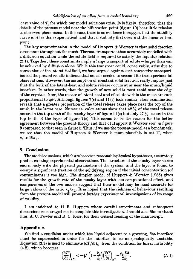
least value of T, for which our model solutions exist. It is likely, therefore, that the details of the present model near the bifurcation point (figure 10) bear little relation to observed phenomena. In this case, there is no evidence to suggest that the stability curve is other than supercritical, and that instability first occurs at the linear critical point.
The key approximation in the model of Huppert & Worster is that solid fraction is constant throughout the mush. Thermal transport is then accurately modelled with a diffusion equation while the solute field is required to satisfy the liquidus relation (2.1). Together, these constraints imply a large transport of solute - larger than can be achieved by diffusion alone. While this transport could, conceivably, arise due to convection of the interstitial fluid, we have argued against such convective transport, indeed the present results indicate that none is needed to account for the experimental observations. However, the assumption of constant solid fraction really implies just that the bulk of the latent-heat and solute release occurs at or near the mush/liquid interface. In other words, that the growth of new solid is most rapid near the edge of the crystals. Now, the release of latent heat and of solute within the mush are each proportional to 74'. Although figures 7 (e) and 11 (e) look similar, close examination reveals that a greater proportion of the total release takes place near the top of the mush in the latter case. Numerical calculations show that 42 yo of the total release occurs in the top tenth of the mushy layer of figure 11 ( e ) but only 27 % occurs in the top tenth of the layer of figure 7(e). This seems to be the reason for the better agreement between the present theory and that of Huppert t Worster seen in figure 9 compared to that seen in figure 5. Thus, if we use the present model as a benchmark, we see that the model of Huppert t Worster is more plausible in set 11, when K, X 1 0 K ~ .
9. Conclusion The model equations, which are based on reasonable physical hypotheses, accurately
predict existing experimental observations. The structure of the mushy layer varies enormously with the physical parameters of the system, and the layer is found to occupy a significant fraction of the solidifying region if the initial concentration (of contaminant) is too high. The simpler model of Huppert t Worster (1985) gives results for the growth rate of the mushy layer with less computational effort, and comparisons of the two models suggest that their model may be most accurate for large values of the ratio K,/K=. It is hoped that the richness of behaviour resulting from the present model will prompt further experimental investigations of its range of validity.
I am indebted to H. E. Huppert whose careful experiments and subsequent discussions encouraged me to complete this investigation. I would also like to thank him, A. C. Fowler and R. C. Kerr, for their critical reading of the manuscript.
Appendix A We find a condition under which the liquid adjacent to a growing, flat interface
must be supercooled in order for the interface to be morphologically unstable. Equation (3.3) is used to eliminate (aT/az)h- from the condition for linear instability (4.2), which becomes

500 M . G. Worster
Comparing this with condition (4.1) shows that supercooling precedes instability if
which can be rearranged to yield
This is re-expressed in terms of the similarity solution as
which is the same as (4.3) once Cf, is replaced by its expression given in (3.9).
Appendix B The boundary condition on the liquid fraction x at the mush/liquid interface was
derived in this paper from a condition of marginal equilibrium. Here, we show that this implies a continuous change in liquid fraction across the interface, i.e. xb = 1, if k, 2 k,. The condition for marginal equilibrium leads to the quadratic equation (6.8) for Xb, which has roots xb = 1 and Xb = xi where
(equation (6.9)). Now, C,(A) is a decreasing function of A , while Cf,(A) is an increasing function of A. Let A, be the critical height of a flat interface at which supercooling first occurs in the liquid. Then, since hb for a mush is always greater than A,,
Ci(Ab) < Ci(Ac) = Cfi(Ac) < cfi(Ab),
so the numerator of (6.9) is always negative. Therefore, xi is negative if the denominator of 16.9)
(B 1)
is positive, and vice versa. In particular, if k, 2 ks then xi is negative, and we must choose Xb = 1 as the physical root of (6.8).
Here, we show that only one of the roots of (6.8), X b = 1 or xb = xi, can lead to a physical solution of the governing differential equations for each particular set of external parameters. If xb = 1 then x;, must be positive in order for x to be less than unity in the mush (7 < Ab). Note first that the solute flux must always be away from the cooled boundary, so C' < 0 everywhere. Equation (6.2) then shows that x increases with 7 (decreases with depth into the mush) provided the factor A , which premultiplies the highest derivatives, is positive. An expression for A is given in (6.4). At the mush/liquid interface it takes the value
Expressions (6.11) for CL and (5.4) for k, can be used to rewrite (B 2) as

Solidification of an alloy from a cooled boundary
while expressions (6.7) for cb and (6.9) for xi can be used to obtain
50 1
Finally, setting x b = 1 produces
Now, the discussion leading to (B 1) explains that the term in square brackets of (B 5 ) is positive if xi is negative and vice versa. If xi is less than zero or greater than one, we must choose xb = 1 as the root of (6.8) since x is a liquid fraction. On the other hand, if 0 < xi < 1 then (B 5 ) shows that X b = 1 makes A , negative, so we must choose X b = xi*
R E F E R E N C E S
ABRAMOWITZ, M. & STEQUN, I. A. 1964 Handbook of Mathematical Functions. U S Government
BATCHELOR, G. K. 1974 Transport properties of two-phase materials with random structure. Ann.
BEN-JACOB, E., GOLDENFELD, N., LANQER, J. S. & SCHON, G. 1983 Dynamicsof interfacial pattern
CARSLAW, H. S. & JAEQER, J. C. 1959 Conduction of Heat in Solids. Oxford University Press. &EN, C. F. & TURNER, J. S. 1980 Crystallization in a double-diffusive system. J. Geophys. Res.
COPLEY, S. M., GIAMEI, A. F., JOHNSON, S. M. 6 HORNBECKER, M. F. 1970 The origin of freckles
FEARN, D. R., LOPER, D. E. & ROBERTS, P. H. 1981 Structure of the earth’s inner core. Nature
FOWLER, A. C. 1986 The formation of freckles in binary alloys. I M A J. Appl. Maths (in press). HILLS, R. N., LOPER, D. E. & ROBERTS, P. H. 1983 A thermodynamically consistent model of
a mushy zone. Q. J. Appl. Maths 36,505-539. HUPPERT, H . E. & WORSTER, M. G. 1985 Dynamic solidification of a binary alloy. Nature 314,
703-707. LANQER, J. S. 1980 Instabilities and pattern formation in crystal growth. Rev. Mod. Phys. 52,l-28. LOPER, D. E. 1983 Structure of the inner core boundary. Geophys. Astrophys. Fluid Dyn. 25,
13S155. MARTIN, S. & KAUFFMAN, P. 1974 The evolution of under-ice melt ponds, or double-diffusion a t
the freezing temperature. J. Fluid Mech. 64, 507-527. MULLINS, W. W. & SEKERKA, R. F. 1964 Stability of a planar interface during solidification of
a dilute binary alloy. J. Appl. Phys. 35, 444-451. RILEY, D. S., SMITH, F. T. & POOTS, G. 1974 The inward solidification of spheres and circular
cylinders. Intl J. Heat Mass Transfer 17, 1507-1516. RUTTER, J. W. & CHALMERS, B. 1953 Prismatic substructure. Can. J. Phys. 31, 15-39. SEKERKA, R. F. 1973 Morphological stability. In Crystal Growth: an Introduction (ed. P. Hartman),
pp. 403-442. North-Holland. SOWARD, A. M. 1980 A unified approach to Stefan’s problem for spheres and cylinders. Proc. R.
SOC. Lond. A 373, 131-147. TURNER, J. S., HUPPERT, H. E. & SPARKS, R. S. J. 1986 Komatiites 11: experimental and
theoretical investigations of post-emplacement cooling and crystallization. J . Petrol. (in press). UNOAR, L. H. & BROWN, R. A. 1984 Cellular interface morphologies in directional solidification.
The one-sided model. Phys. Rev. B 29, 1367-1380. VERONIS, G. 1970 The analogy between rotating and stratified flows. Ann. Rev. Fluid Mech. 2,
37-66. WORSTER, M. G. 1983 Convective flow problems in geological fluid dynamics. Ph.D. thesis,
University of Cambridge.
Printing Office, Washington.
Rev. Fluid Mech. 6, 227-255.
formation. Phys. Rev. Lett. 51, 193C1932.
85, 2573-2593.
in unidirectionally solidified castings. Metall. Trans. 1, 2 193-2204.
292, 232-233.