solidworks 2011 · solidworks simulation hands on test drive the seabotix lbv150 5 today, you will...
TRANSCRIPT
SolidWorks® 2011
SolidWorks Simulation Hands-on Test Drive
Dassault Systèmes SolidWorks Corp.300 Baker AvenueConcord, MA 01742 USAPhone: 1 800 693 9000
Outside the US: 1 978 371 5011Fax: 1 978 371 7303

© 1995-2009, Dassault Systèmes SolidWorks Corporation, a Dassault Systèmes S.A. company, 300 Baker AvenueConcord, Massachusetts 01742 USA. All Rights Reserved.
The information and the software discussed in this document are subject to change without notice and are not commitments by Dassault Systèmes SolidWorks Corporation (DS SolidWorks).No material may be reproduced or transmitted in any form or by any means, electronic or mechanical, for any purpose without the express written permission of DS SolidWorks.The software discussed in this document is furnished under a license and may be used or copied only in accordance with the terms of this license. All warranties given by DS SolidWorks as to the software and documentation are set forth in the SolidWorks Corporation License and Subscription Service Agreement, and nothing stated in, or implied by, this document or its contents shall be considered or deemed a modification or amendment of such warranties.
Patent Notices for SolidWorks Standard, Premium, and Professional Products.US Patents 5,815,154; 6,219,049; 6,219,055; 6,603,486; 6,611,725; and 6,844,877 and certain other foreign patents, including EP 1,116,190 and JP 3,517,643. US and foreign patents pending, e.g., EP 1,116,190 and JP 3,517,643). U.S. and foreign patents pending.
Trademarks and Other Notices for All SolidWorks Products.SolidWorks, 3D PartStream.NET, 3D ContentCentral, PDMWorks, eDrawings, and the eDrawings logo are registered trademarks and FeatureManager is a jointly owned registered trademark of DS SolidWorks. SolidWorks Enterprise PDM SolidWorks Simulation, SolidWorks Flow Simulation, and SolidWorks 2010 are product names of DS SolidWorks.CircuitWorks, Feature Palette, FloXpress, PhotoWorks, TolAnalyst, and XchangeWorks are trademarks of DS SolidWorks.FeatureWorks is a registered trademark of Geometric Ltd.Other brand or product names are trademarks of their respective holders.
COMMERCIAL COMPUTER SOFTWARE - PROPRIETARY.US Government Restricted Rights. Use, duplication, or disclosure by the government is subject to restrictions as set forth in FAR 52.227-19 (Commercial Computer Software - Restricted Rights), DFARS 227.7202 (Commercial Computer Software and Commercial Computer Software Documentation), and in the license agreement, as applicable.Contractor/Manufacturer:Dassault Systèmes SolidWorks Corp, 300 Baker Avenue, Concord, Massachusetts 01742 USA
Copyright Notices for SolidWorks Standard, Premium, and Professional Products.Portions of this software © 1990-2009 Siemens Product Lifecycle Management Software III (GB) Ltd.Portions of this software © 1998-2009 Geometric Ltd.Portions of this software © 1986-2009 mental images GmbH & Co.KG.Portions of this software © 1996-2009 Microsoft Corporation. All Rights Reserved.Portions of this software © 2000-2009 Tech Soft 3DPortions of this software © 1998-2008 3Dconnexion.This software is based in part on the work of the Independent JPEG Group. All Rights Reserved.Portions of this software incorporate PhyX™ by NVIDIA 2006-2009.Portions of this software are copyrighted by and are the property of UGS Corp. © 2009.Portions of this software © 2001 - 2009 Luxology, Inc. All Rights Reserved, Patents Pending.Portions of this software © 2007 - 2009 DriveWorks Ltd.Copyright 1984 - 2009 Adobe Systems, Inc. and its licensors. All rights reserved. Protected by U.S. Patents 5,929,866; 5,943,063; 6,289,364; 6,639,593; 6,743,382; Patents Pending. Adobe, the Adobe logo, Acrobat, the Adobe PDF logo, Distiller and Reader are registered trademarks or trademarks of Adobe Systems Inc. in the U.S. and other countries.For more copyright information, in SolidWorks see Help, About SolidWorks.Other portions of SolidWorks 2010 are licensed from DS SolidWorks licensors.
Copyright Notices for SolidWorks Simulation.Portions of this software © 2008 Solversoft Corporation. PCGLSS © 1992 - 2007 Computational Applications and System Integration, Inc. All Rights Reserved.Portions of this product are distributed under license from DC Micro Development, Copyright © 1994 - 2005 DC Micro Development. All Rights Reserved.
Document Number: MKSIMHOTBK1109
SolidWorks Simulation
i
Table of Contents
Introduction................................................................................................................... 3The SeaBotix LBV150 ................................................................................................. 4User Interface................................................................................................................ 6
Menu Bar Toolbar .................................................................................................. 6Menu Bar Menu ..................................................................................................... 6Drop-down menu / Context Toolbar ...................................................................... 7Keyboard Shortcuts................................................................................................ 7FeatureManager Design Tree................................................................................. 7SolidWorks Simulation CommandManager Tab ................................................... 8Mouse Buttons ....................................................................................................... 8System Feedback.................................................................................................... 9Getting SolidWorks Help....................................................................................... 9Getting SolidWorks Simulation Help. ................................................................. 10SolidWorks Tutorials and SolidWorks Simulation Tutorials .............................. 11
SolidWorks and SolidWorks Simulation.................................................................... 13Analyze the Housing................................................................................................... 14
Starting a SolidWorks Session ............................................................................. 15Create a Static Analysis Study.................................................................................... 19
Creating a Static Analysis Study.......................................................................... 20Assigning Materials in SolidWorks Simulation ......................................................... 21
Selecting parts and Applying Material in SolidWorks Simulation ..................... 22Applying Fixtures ....................................................................................................... 23
Applying a Fixture ............................................................................................... 24Applying Loads .......................................................................................................... 26
Applying a Pressure Load .................................................................................... 27Creating a Mesh and Running the Analysis ............................................................... 30
Creating a Compatible Mesh................................................................................ 31Creating a Mesh ................................................................................................... 32
Viewing the Results.................................................................................................... 34
SolidWorks Simulation
ii
View the Results .................................................................................................. 35Creating a SolidWorks eDrawings File ...................................................................... 43
Creating a SolidWorks eDrawings file ................................................................ 44Generating a Report.................................................................................................... 47
Generating a Static Study Report......................................................................... 48Analysis 2 - Static Study 2.......................................................................................... 50
Creating Analysis 2 - Static Study 2 .................................................................... 51SolidWorks Simulation Conclusion ........................................................................... 60SolidWorks Simulation Professional.......................................................................... 62Trend Tracker Analysis .............................................................................................. 63Thermal Analysis........................................................................................................ 74
Create the Thermal Analysis Study...................................................................... 75Applying the EndCap Material. ........................................................................... 76
Thermal Loads and Boundary Conditions.................................................................. 77Applying a Thermal Load .................................................................................... 78Applying Convection ........................................................................................... 79Creating a Mesh and running an Analysis ........................................................... 81Applying the Probe tool ....................................................................................... 83
Modify the Design ...................................................................................................... 84Create the Second Analysis.................................................................................. 85
Drop Test Analysis ..................................................................................................... 89Creating a Drop Test Study.................................................................................. 90Meshing the Model .............................................................................................. 92
Running the Analysis.................................................................................................. 93Animating the Plot ............................................................................................... 95
Optimization Analysis ................................................................................................ 98Creating an Optimization Analysis ...................................................................... 99
Fatigue Analysis ....................................................................................................... 108Creating a Fatigue Analysis ............................................................................... 109Applying Material .............................................................................................. 110Adding a Fixture ................................................................................................ 111Applying a Force................................................................................................ 113Meshing and Running the Model....................................................................... 114Perform a Fatigue Check Plot. ........................................................................... 115Creating a New Fatigue Study. .......................................................................... 116Applying a Load Factor ..................................................................................... 119
SolidWorks Simulation Professional Conclusion..................................................... 120SolidWorks Flow Simulation ................................................................................... 122
Starting a SolidWorks Flow Simulation Session ............................................... 123Applying Flow Trajectories...................................................................................... 134
Applying Flow Trajectories ............................................................................... 135SolidWorks Flow Simulation ................................................................................... 140
SolidWorks Simulation
iii
SolidWorks Motion .................................................................................................. 142Starting a SolidWorks Motion Session .............................................................. 143
Applying Motion to a Component............................................................................ 145Applying Linear Motion .................................................................................... 146
Applying Forces........................................................................................................ 148Applying Force to the Gripper Fingers .............................................................. 149
SolidWorks Motion Conclusion ............................................................................... 155

SolidWorks Simulation
iv

Hands on Test Drive
When you complete this manual, you will have experienced firsthand an introduction to the capabilities of SolidWorks® Simulation products, including:
SolidWorks® SimulationSolidWorks® Simulation ProfessionalSolidWorks® Flow SimulationSolidWorks® Motion

Hands on Test Drive SolidWorks Simulation
SolidWorks Simulation Hands on Test Drive
Introduction 3
IntroductionThe SolidWorks® Simulation Hands-on Test Drive provides you with an understanding of the capabilities and benefits of using SolidWorks® Simulation analysis software to perform powerful analysis from your desktop. Only SolidWorks Simulation validation tools provide seamless integration with SolidWorks® 3D CAD software, with the benefit of the easy-to-use Windows® user interface.Learn how you can use SolidWorks Simulations to perform stress analysis on your design; SolidWorks® Simulation Professional to perform stress, thermal, optimization, and fatigue analysis; SolidWorks® Motion to perform motion simulations; and SolidWorks® Flow Simulation to perform fluid-flow analysis on your designs.
Hands on Test Drive SolidWorks Simulation
4 The SeaBotix LBV150
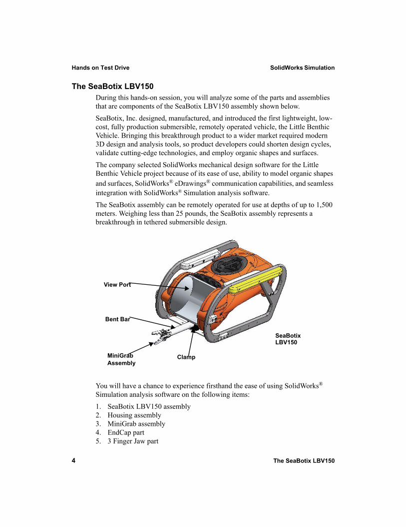
The SeaBotix LBV150 During this hands-on session, you will analyze some of the parts and assemblies that are components of the SeaBotix LBV150 assembly shown below.SeaBotix, Inc. designed, manufactured, and introduced the first lightweight, low-cost, fully production submersible, remotely operated vehicle, the Little Benthic Vehicle. Bringing this breakthrough product to a wider market required modern 3D design and analysis tools, so product developers could shorten design cycles, validate cutting-edge technologies, and employ organic shapes and surfaces.The company selected SolidWorks mechanical design software for the Little Benthic Vehicle project because of its ease of use, ability to model organic shapes and surfaces, SolidWorks® eDrawings® communication capabilities, and seamless integration with SolidWorks® Simulation analysis software. The SeaBotix assembly can be remotely operated for use at depths of up to 1,500 meters. Weighing less than 25 pounds, the SeaBotix assembly represents a breakthrough in tethered submersible design.
You will have a chance to experience firsthand the ease of using SolidWorks® Simulation analysis software on the following items: 1. SeaBotix LBV150 assembly2. Housing assembly3. MiniGrab assembly4. EndCap part5. 3 Finger Jaw part
SeaBotixLBV150
ClampMiniGrabAssembly
Bent Bar
View Port
SolidWorks Simulation Hands on Test Drive
The SeaBotix LBV150 5
Today, you will use the SolidWorks Simulation family of products:
SolidWorks® Simulation - The static analysis application that determines the stresses on the Housing assembly and the EndCap part.SolidWorks® Simulation Professional - The static, thermal, drop test, and optimization analysis application that validate the design of the Housing assembly, EndCap part, and the 3 Finger Jaw part.SolidWorks® Motion - The ridge body motion analysis application that simulates the mechanical operation of the motorized MiniGrab assembly and the physical forces it generates.SolidWorks® Flow Simulation - The fluid flow analysis application that provides insight into the SeaBotix LBV150 assembly related to fluid flow and forces on the immersed model.
Hands on Test Drive SolidWorks Simulation
6 User Interface
User InterfaceThe first thing that you notice about the SolidWorks® user interface is that it looks like Microsoft® Windows®. That is because it is Windows!The SolidWorks 2010 (UI) is designed to make maximum use of the Graphics area space. Displayed toolbars and commands are kept to a minimum. Communicate with SolidWorks through the drop-down menus, Context document sensitive toolbars, Consolidated toolbars, or the CommandManager tabs.
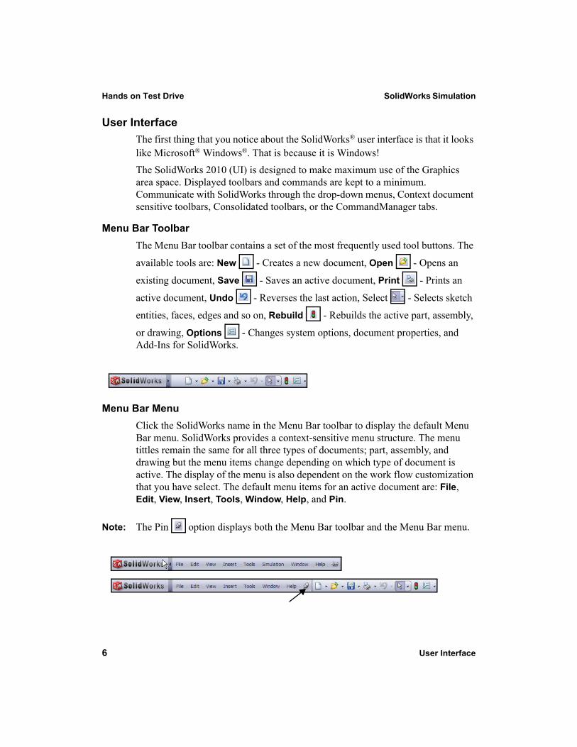
Menu Bar ToolbarThe Menu Bar toolbar contains a set of the most frequently used tool buttons. The
available tools are: New - Creates a new document, Open - Opens an
existing document, Save - Saves an active document, Print - Prints an
active document, Undo - Reverses the last action, Select - Selects sketch
entities, faces, edges and so on, Rebuild - Rebuilds the active part, assembly,
or drawing, Options - Changes system options, document properties, and Add-Ins for SolidWorks.
Menu Bar MenuClick the SolidWorks name in the Menu Bar toolbar to display the default Menu Bar menu. SolidWorks provides a context-sensitive menu structure. The menu tittles remain the same for all three types of documents; part, assembly, and drawing but the menu items change depending on which type of document is active. The display of the menu is also dependent on the work flow customization that you have select. The default menu items for an active document are: File, Edit, View, Insert, Tools, Window, Help, and Pin.
Note: The Pin option displays both the Menu Bar toolbar and the Menu Bar menu.
SolidWorks Simulation Hands on Test Drive
User Interface 7
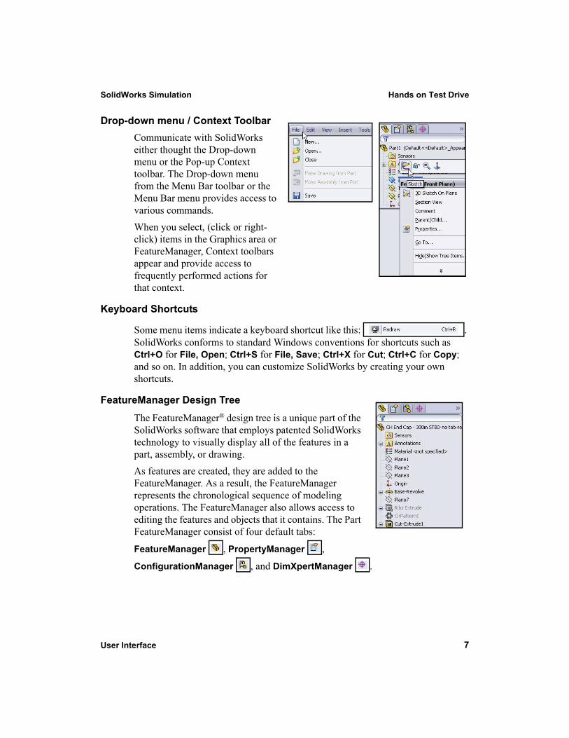
Drop-down menu / Context ToolbarCommunicate with SolidWorks either thought the Drop-down menu or the Pop-up Context toolbar. The Drop-down menu from the Menu Bar toolbar or the Menu Bar menu provides access to various commands. When you select, (click or right-click) items in the Graphics area or FeatureManager, Context toolbars appear and provide access to frequently performed actions for that context.
Keyboard Shortcuts
Some menu items indicate a keyboard shortcut like this: . SolidWorks conforms to standard Windows conventions for shortcuts such as Ctrl+O for File, Open; Ctrl+S for File, Save; Ctrl+X for Cut; Ctrl+C for Copy; and so on. In addition, you can customize SolidWorks by creating your own shortcuts.
FeatureManager Design Tree
The FeatureManager® design tree is a unique part of the SolidWorks software that employs patented SolidWorks technology to visually display all of the features in a part, assembly, or drawing. As features are created, they are added to the FeatureManager. As a result, the FeatureManager represents the chronological sequence of modeling operations. The FeatureManager also allows access to editing the features and objects that it contains. The Part FeatureManager consist of four default tabs:
FeatureManager , PropertyManager ,
ConfigurationManager , and DimXpertManager .
Hands on Test Drive SolidWorks Simulation
8 User Interface
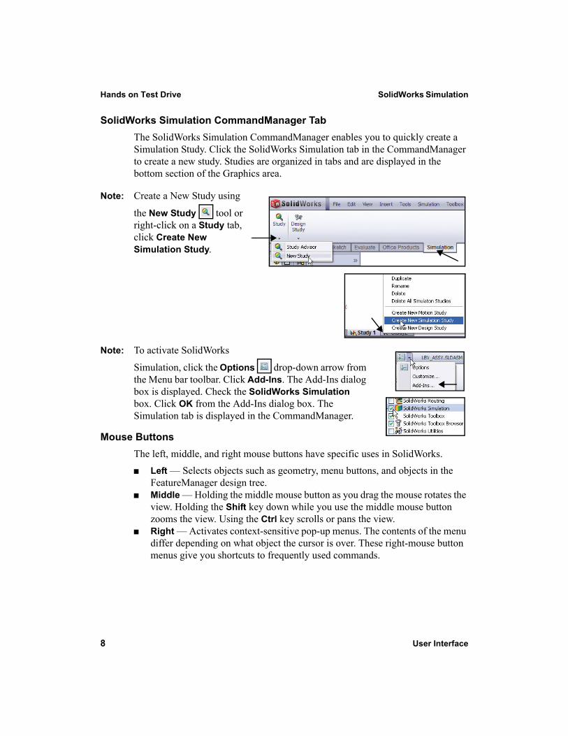
SolidWorks Simulation CommandManager TabThe SolidWorks Simulation CommandManager enables you to quickly create a Simulation Study. Click the SolidWorks Simulation tab in the CommandManager to create a new study. Studies are organized in tabs and are displayed in the bottom section of the Graphics area.
Note: Create a New Study using
the New Study tool or right-click on a Study tab, click Create New Simulation Study.
Note: To activate SolidWorks
Simulation, click the Options drop-down arrow from the Menu bar toolbar. Click Add-Ins. The Add-Ins dialog box is displayed. Check the SolidWorks Simulation box. Click OK from the Add-Ins dialog box. The Simulation tab is displayed in the CommandManager.
Mouse ButtonsThe left, middle, and right mouse buttons have specific uses in SolidWorks.
Left — Selects objects such as geometry, menu buttons, and objects in the FeatureManager design tree.Middle — Holding the middle mouse button as you drag the mouse rotates the view. Holding the Shift key down while you use the middle mouse button zooms the view. Using the Ctrl key scrolls or pans the view.Right — Activates context-sensitive pop-up menus. The contents of the menu differ depending on what object the cursor is over. These right-mouse button menus give you shortcuts to frequently used commands.
SolidWorks Simulation Hands on Test Drive
User Interface 9
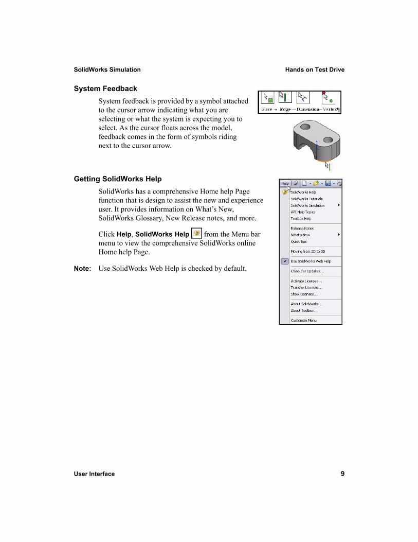
System FeedbackSystem feedback is provided by a symbol attached to the cursor arrow indicating what you are selecting or what the system is expecting you to select. As the cursor floats across the model, feedback comes in the form of symbols riding next to the cursor arrow.
Getting SolidWorks HelpSolidWorks has a comprehensive Home help Page function that is design to assist the new and experience user. It provides information on What’s New, SolidWorks Glossary, New Release notes, and more.
Click Help, SolidWorks Help from the Menu bar menu to view the comprehensive SolidWorks online Home help Page.
Note: Use SolidWorks Web Help is checked by default.
Hands on Test Drive SolidWorks Simulation
10 User Interface
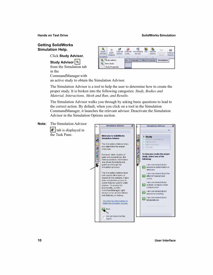
Getting SolidWorks Simulation Help.
Click Study Advisor,
Study Advisor from the Simulation tab in the CommandManager with an active study to obtain the Simulation Advisor. The Simulation Advisor is a tool to help the user to determine how to create the proper study. It is broken into the following categories: Study, Bodies and Material, Interactions, Mesh and Run, and Results.The Simulation Advisor walks you through by asking basic questions to lead to the correct action. By default, when you click on a tool in the Simulation CommandManager, it launches the relevant advisor. Deactivate the Simulation Advisor in the Simulation Options section.
Note: The Simulation Advisor
tab is displayed in the Task Pane.
SolidWorks Simulation Hands on Test Drive
User Interface 11
SolidWorks Tutorials and SolidWorks Simulation Tutorials
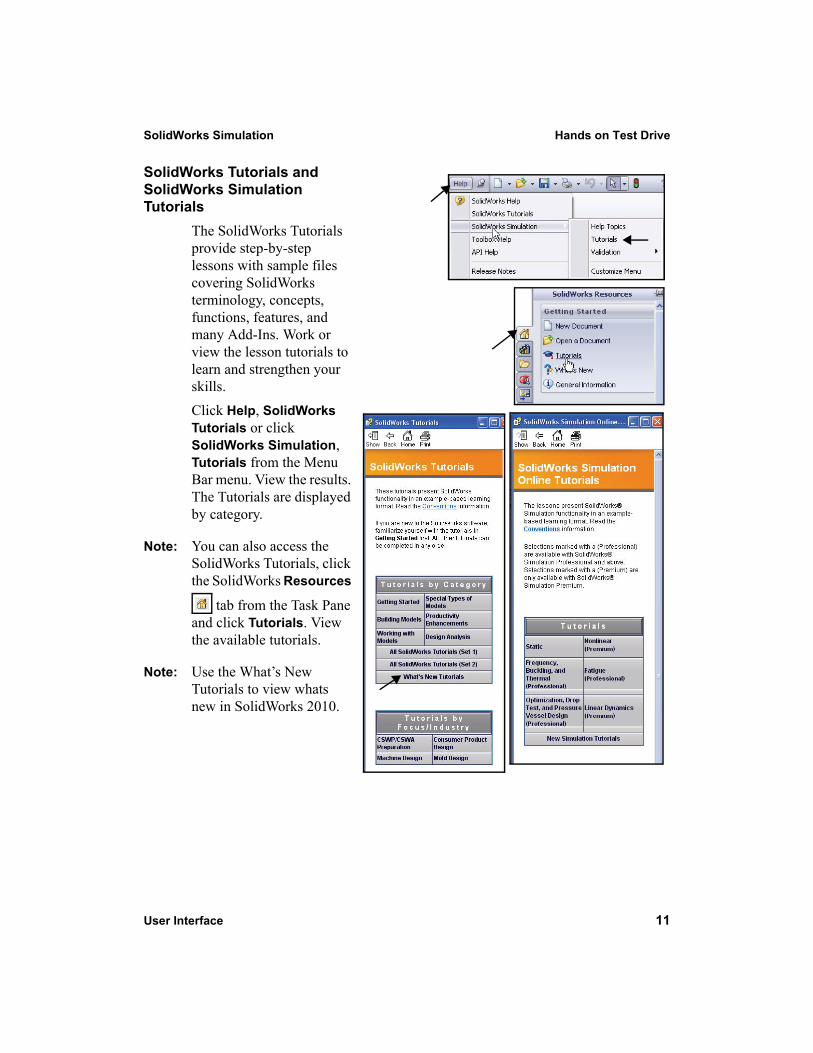
The SolidWorks Tutorials provide step-by-step lessons with sample files covering SolidWorks terminology, concepts, functions, features, and many Add-Ins. Work or view the lesson tutorials to learn and strengthen your skills. Click Help, SolidWorks Tutorials or click SolidWorks Simulation, Tutorials from the Menu Bar menu. View the results. The Tutorials are displayed by category.
Note: You can also access the SolidWorks Tutorials, click the SolidWorks Resources
tab from the Task Pane and click Tutorials. View the available tutorials.
Note: Use the What’s New Tutorials to view whats new in SolidWorks 2010.

SolidWorks Simulation SolidWorks Simulation
12 User Interface
SolidWorks Simulation
SolidWorks® Simulation is a design analysis application fully integrated with SolidWorks. It provides a one-screen solution for stress analysis and also enables you to solve large problems quickly using your personal computer. In this section of SolidWorks Simulation, you will address the following:
SolidWorks Simulation User InterfaceThe integration between SolidWorks Simulation and SolidWorksCreating Design StudiesUnderstanding the Analysis StepsAssigning MaterialsApplying Fixtures and LoadsMeshing the ModelRunning the AnalysisViewing the Results
Time: 55 - 60 minutes
SolidWorks Simulation SolidWorks Simulation
SolidWorks and SolidWorks Simulation 13
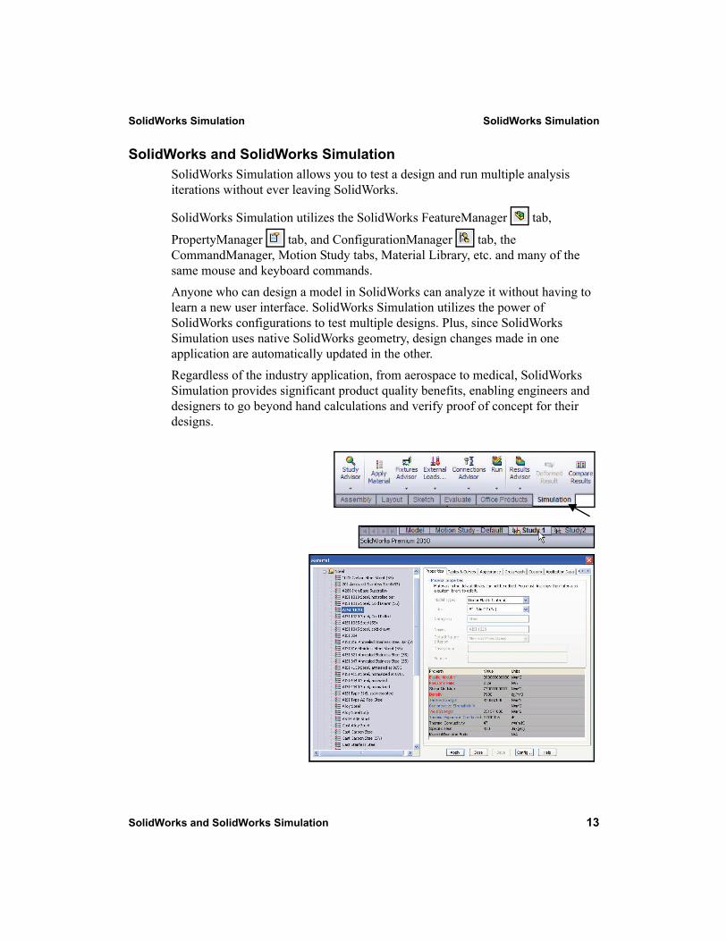
SolidWorks and SolidWorks SimulationSolidWorks Simulation allows you to test a design and run multiple analysis iterations without ever leaving SolidWorks.
SolidWorks Simulation utilizes the SolidWorks FeatureManager tab,
PropertyManager tab, and ConfigurationManager tab, the CommandManager, Motion Study tabs, Material Library, etc. and many of the same mouse and keyboard commands. Anyone who can design a model in SolidWorks can analyze it without having to learn a new user interface. SolidWorks Simulation utilizes the power of SolidWorks configurations to test multiple designs. Plus, since SolidWorks Simulation uses native SolidWorks geometry, design changes made in one application are automatically updated in the other.Regardless of the industry application, from aerospace to medical, SolidWorks Simulation provides significant product quality benefits, enabling engineers and designers to go beyond hand calculations and verify proof of concept for their designs.
SolidWorks Simulation SolidWorks Simulation
14 Analyze the Housing
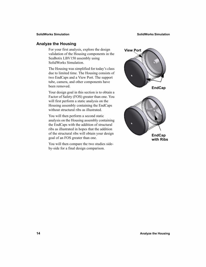
Analyze the HousingFor your first analysis, explore the design validation of the Housing components in the SeaBotix LBV150 assembly using SolidWorks Simulation.The Housing was simplified for today’s class due to limited time. The Housing consists of two EndCaps and a View Port. The support tube, camera, and other components have been removed. Your design goal in this section is to obtain a Factor of Safety (FOS) greater than one. You will first perform a static analysis on the Housing assembly containing the EndCaps without structural ribs as illustrated. You will then perform a second static analysis on the Housing assembly containing the EndCaps with the addition of structural ribs as illustrated in hopes that the addition of the structural ribs will obtain your design goal of an FOS greater than one. You will then compare the two studies side-by-side for a final design comparison.
View Port
EndCap with Ribs
EndCap
SolidWorks Simulation SolidWorks Simulation
Analyze the Housing 15
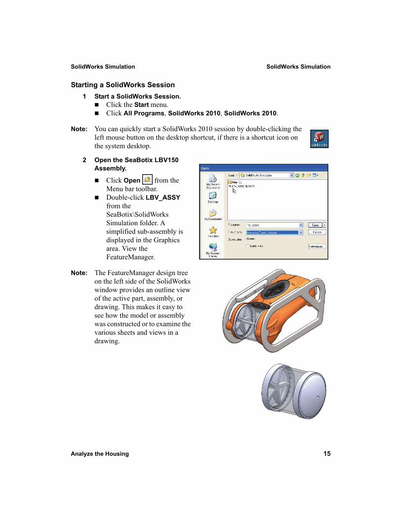
Starting a SolidWorks Session1 Start a SolidWorks Session.
Click the Start menu. Click All Programs, SolidWorks 2010, SolidWorks 2010.
Note: You can quickly start a SolidWorks 2010 session by double-clicking the left mouse button on the desktop shortcut, if there is a shortcut icon on the system desktop.
2 Open the SeaBotix LBV150 Assembly.
Click Open from the Menu bar toolbar. Double-click LBV_ASSY from the SeaBotix\SolidWorks Simulation folder. A simplified sub-assembly is displayed in the Graphics area. View the FeatureManager.
Note: The FeatureManager design tree on the left side of the SolidWorks window provides an outline view of the active part, assembly, or drawing. This makes it easy to see how the model or assembly was constructed or to examine the various sheets and views in a drawing.
SolidWorks Simulation SolidWorks Simulation
16 Analyze the Housing
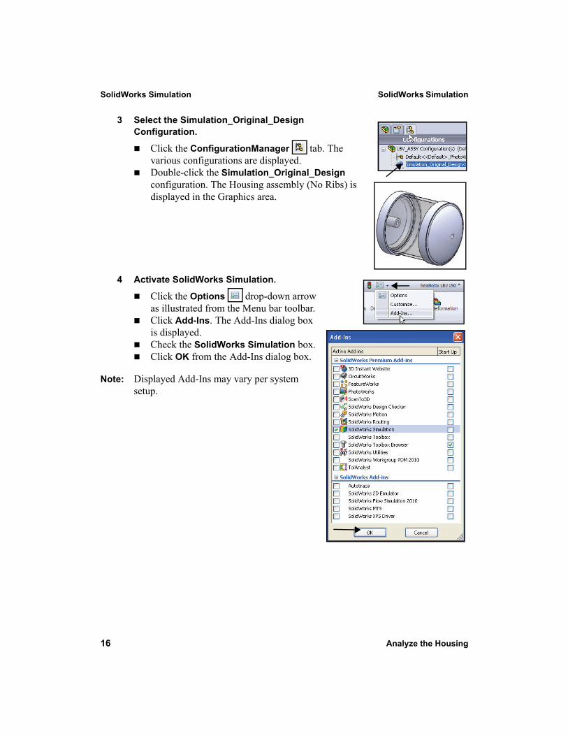
3 Select the Simulation_Original_Design Configuration.
Click the ConfigurationManager tab. The various configurations are displayed.Double-click the Simulation_Original_Design configuration. The Housing assembly (No Ribs) is displayed in the Graphics area.
4 Activate SolidWorks Simulation.
Click the Options drop-down arrow as illustrated from the Menu bar toolbar. Click Add-Ins. The Add-Ins dialog box is displayed.Check the SolidWorks Simulation box. Click OK from the Add-Ins dialog box.
Note: Displayed Add-Ins may vary per system setup.
SolidWorks Simulation SolidWorks Simulation
Analyze the Housing 17
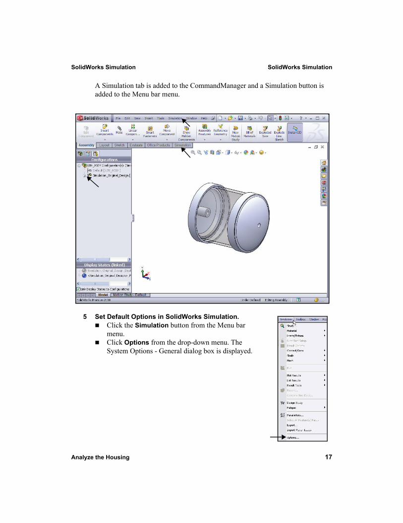
A Simulation tab is added to the CommandManager and a Simulation button is added to the Menu bar menu.
5 Set Default Options in SolidWorks Simulation.Click the Simulation button from the Menu bar menu. Click Options from the drop-down menu. The System Options - General dialog box is displayed.
SolidWorks Simulation SolidWorks Simulation
18 Analyze the Housing
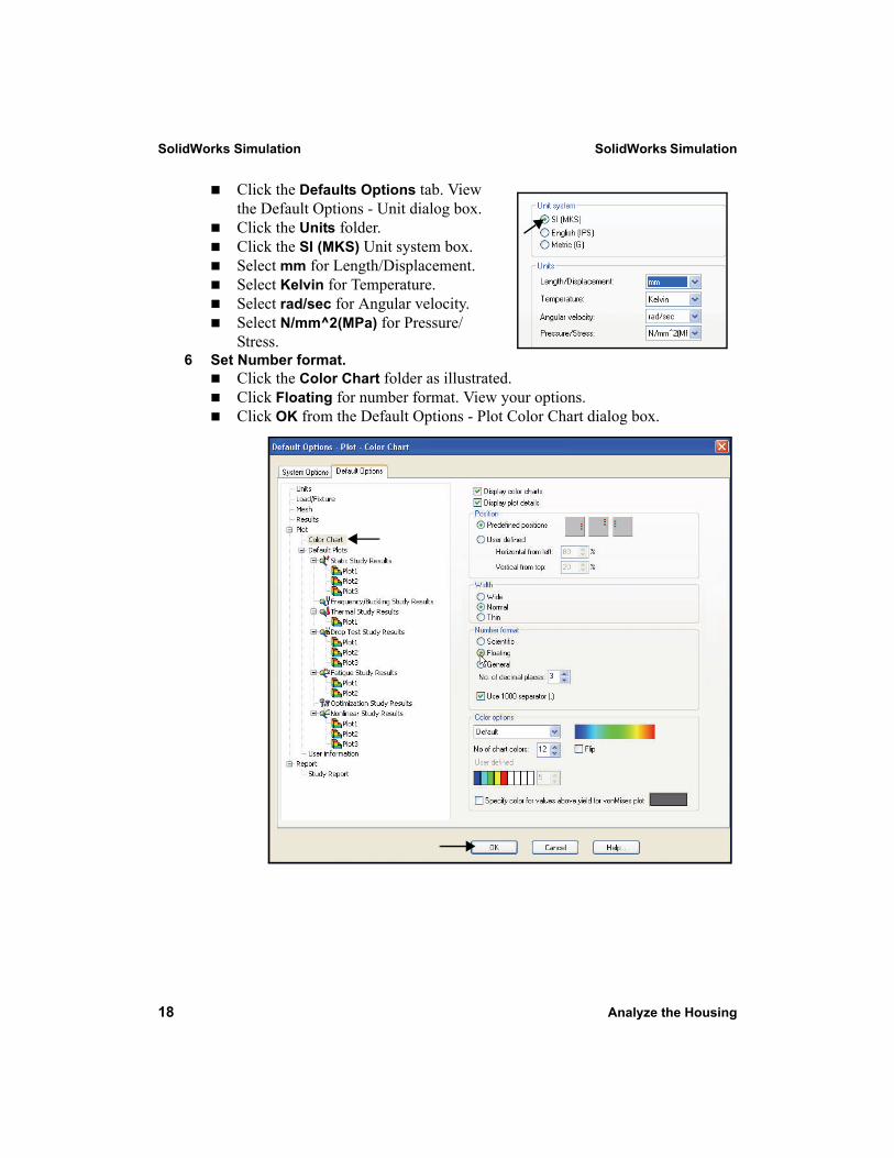
Click the Defaults Options tab. View the Default Options - Unit dialog box.Click the Units folder. Click the SI (MKS) Unit system box.Select mm for Length/Displacement.Select Kelvin for Temperature.Select rad/sec for Angular velocity.Select N/mm^2(MPa) for Pressure/Stress.
6 Set Number format.Click the Color Chart folder as illustrated.Click Floating for number format. View your options.Click OK from the Default Options - Plot Color Chart dialog box.
SolidWorks Simulation SolidWorks Simulation
Create a Static Analysis Study 19
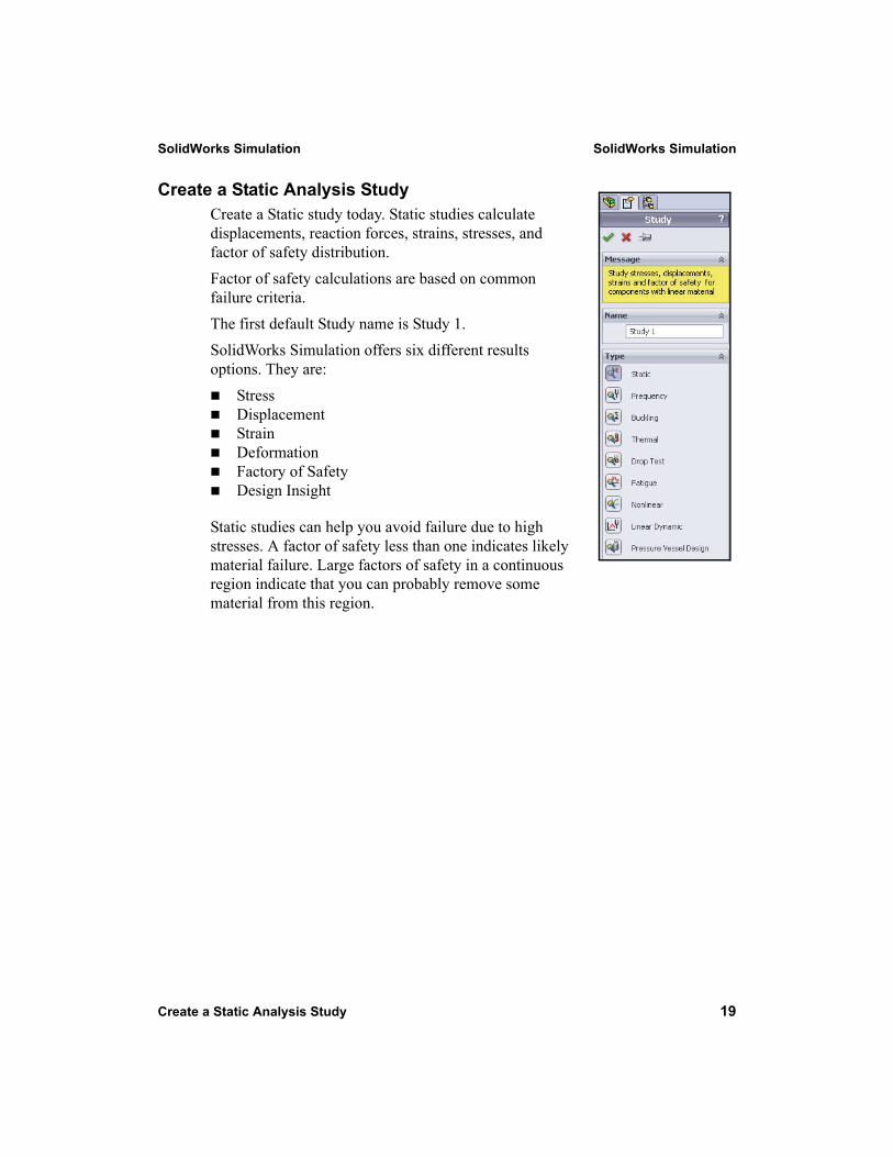
Create a Static Analysis StudyCreate a Static study today. Static studies calculate displacements, reaction forces, strains, stresses, and factor of safety distribution. Factor of safety calculations are based on common failure criteria. The first default Study name is Study 1.SolidWorks Simulation offers six different results options. They are:
StressDisplacementStrainDeformationFactory of SafetyDesign Insight
Static studies can help you avoid failure due to high stresses. A factor of safety less than one indicates likely material failure. Large factors of safety in a continuous region indicate that you can probably remove some material from this region.
SolidWorks Simulation SolidWorks Simulation
20 Create a Static Analysis Study
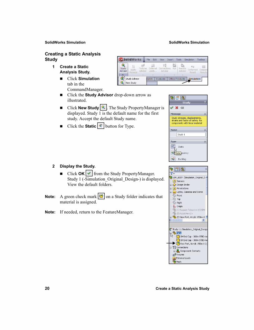
Creating a Static Analysis Study
1 Create a Static Analysis Study.
Click Simulation tab in the CommandManager. Click the Study Advisor drop-down arrow as illustrated. Click New Study . The Study PropertyManager is displayed. Study 1 is the default name for the first study. Accept the default Study name.Click the Static button for Type.
2 Display the Study.
Click OK from the Study PropertyManager. Study 1 (-Simulation_Original_Design-) is displayed. View the default folders.
Note: A green check mark on a Study folder indicates that material is assigned.
Note: If needed, return to the FeatureManager.
SolidWorks Simulation SolidWorks Simulation
Assigning Materials in SolidWorks Simulation 21
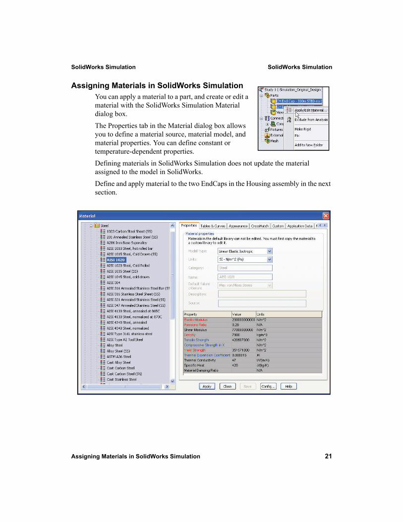
Assigning Materials in SolidWorks SimulationYou can apply a material to a part, and create or edit a material with the SolidWorks Simulation Material dialog box.The Properties tab in the Material dialog box allows you to define a material source, material model, and material properties. You can define constant or temperature-dependent properties.Defining materials in SolidWorks Simulation does not update the material assigned to the model in SolidWorks.Define and apply material to the two EndCaps in the Housing assembly in the next section.
SolidWorks Simulation SolidWorks Simulation
22 Assigning Materials in SolidWorks Simulation
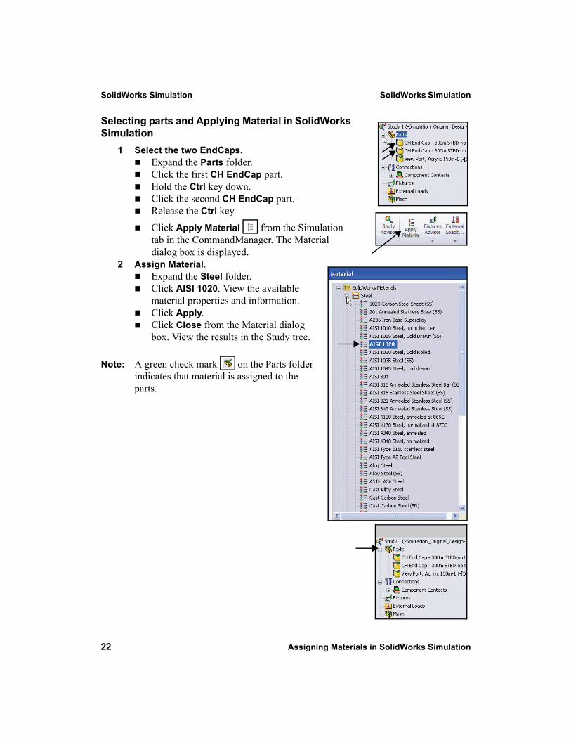
Selecting parts and Applying Material in SolidWorks Simulation
1 Select the two EndCaps.Expand the Parts folder.Click the first CH EndCap part. Hold the Ctrl key down.Click the second CH EndCap part.Release the Ctrl key.Click Apply Material from the Simulation tab in the CommandManager. The Material dialog box is displayed.
2 Assign Material.Expand the Steel folder. Click AISI 1020. View the available material properties and information.Click Apply.Click Close from the Material dialog box. View the results in the Study tree.
Note: A green check mark on the Parts folder indicates that material is assigned to the parts.
SolidWorks Simulation SolidWorks Simulation
Applying Fixtures 23
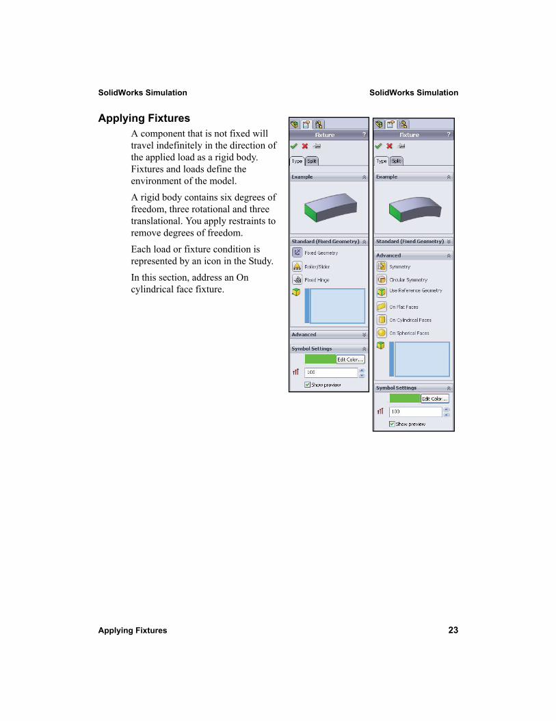
Applying FixturesA component that is not fixed will travel indefinitely in the direction of the applied load as a rigid body. Fixtures and loads define the environment of the model. A rigid body contains six degrees of freedom, three rotational and three translational. You apply restraints to remove degrees of freedom. Each load or fixture condition is represented by an icon in the Study. In this section, address an On cylindrical face fixture.
SolidWorks Simulation SolidWorks Simulation
24 Applying Fixtures
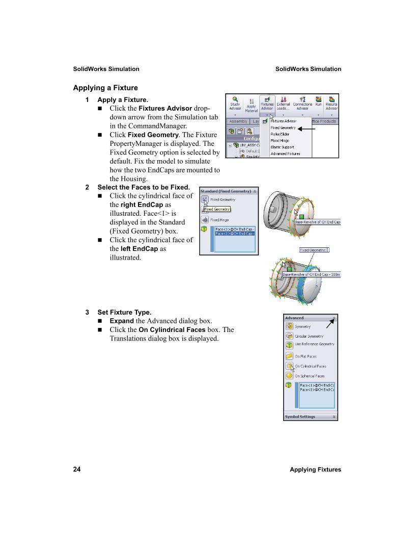
Applying a Fixture1 Apply a Fixture.
Click the Fixtures Advisor drop-down arrow from the Simulation tab in the CommandManager. Click Fixed Geometry. The Fixture PropertyManager is displayed. The Fixed Geometry option is selected by default. Fix the model to simulate how the two EndCaps are mounted to the Housing.
2 Select the Faces to be Fixed.Click the cylindrical face of the right EndCap as illustrated. Face<1> is displayed in the Standard (Fixed Geometry) box. Click the cylindrical face of the left EndCap as illustrated.
3 Set Fixture Type.Expand the Advanced dialog box.Click the On Cylindrical Faces box. The Translations dialog box is displayed.
SolidWorks Simulation SolidWorks Simulation
Applying Fixtures 25
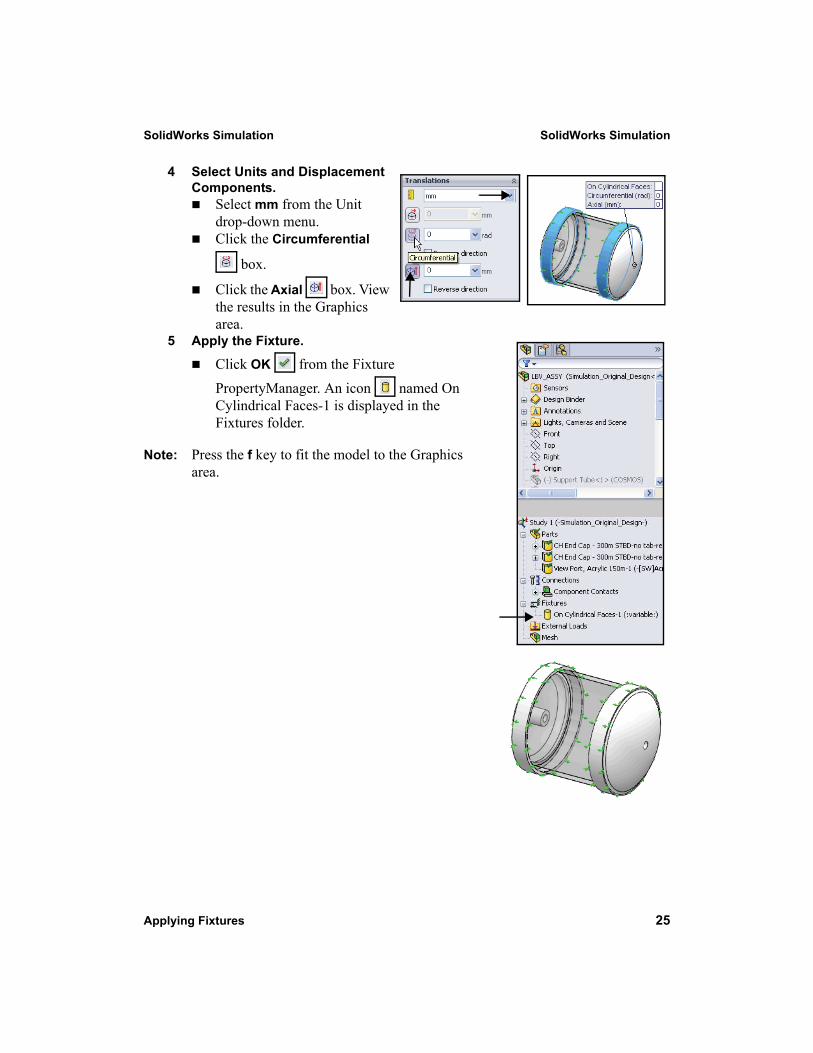
4 Select Units and Displacement Components.
Select mm from the Unit drop-down menu.Click the Circumferential
box.
Click the Axial box. View the results in the Graphics area.
5 Apply the Fixture.
Click OK from the Fixture
PropertyManager. An icon named On Cylindrical Faces-1 is displayed in the Fixtures folder.
Note: Press the f key to fit the model to the Graphics area.
SolidWorks Simulation SolidWorks Simulation
26 Applying Loads
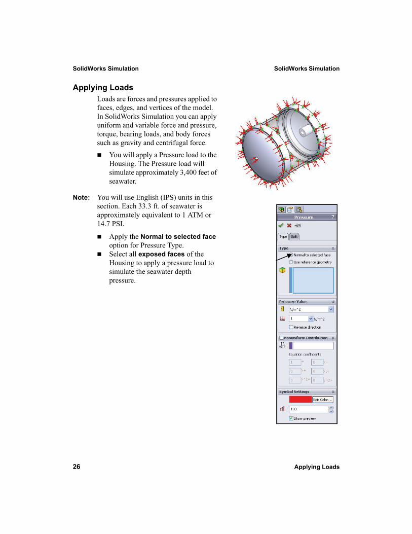
Applying LoadsLoads are forces and pressures applied to faces, edges, and vertices of the model. In SolidWorks Simulation you can apply uniform and variable force and pressure, torque, bearing loads, and body forces such as gravity and centrifugal force.
You will apply a Pressure load to the Housing. The Pressure load will simulate approximately 3,400 feet of seawater.
Note: You will use English (IPS) units in this section. Each 33.3 ft. of seawater is approximately equivalent to 1 ATM or 14.7 PSI.
Apply the Normal to selected face option for Pressure Type. Select all exposed faces of the Housing to apply a pressure load to simulate the seawater depth pressure.
SolidWorks Simulation SolidWorks Simulation
Applying Loads 27
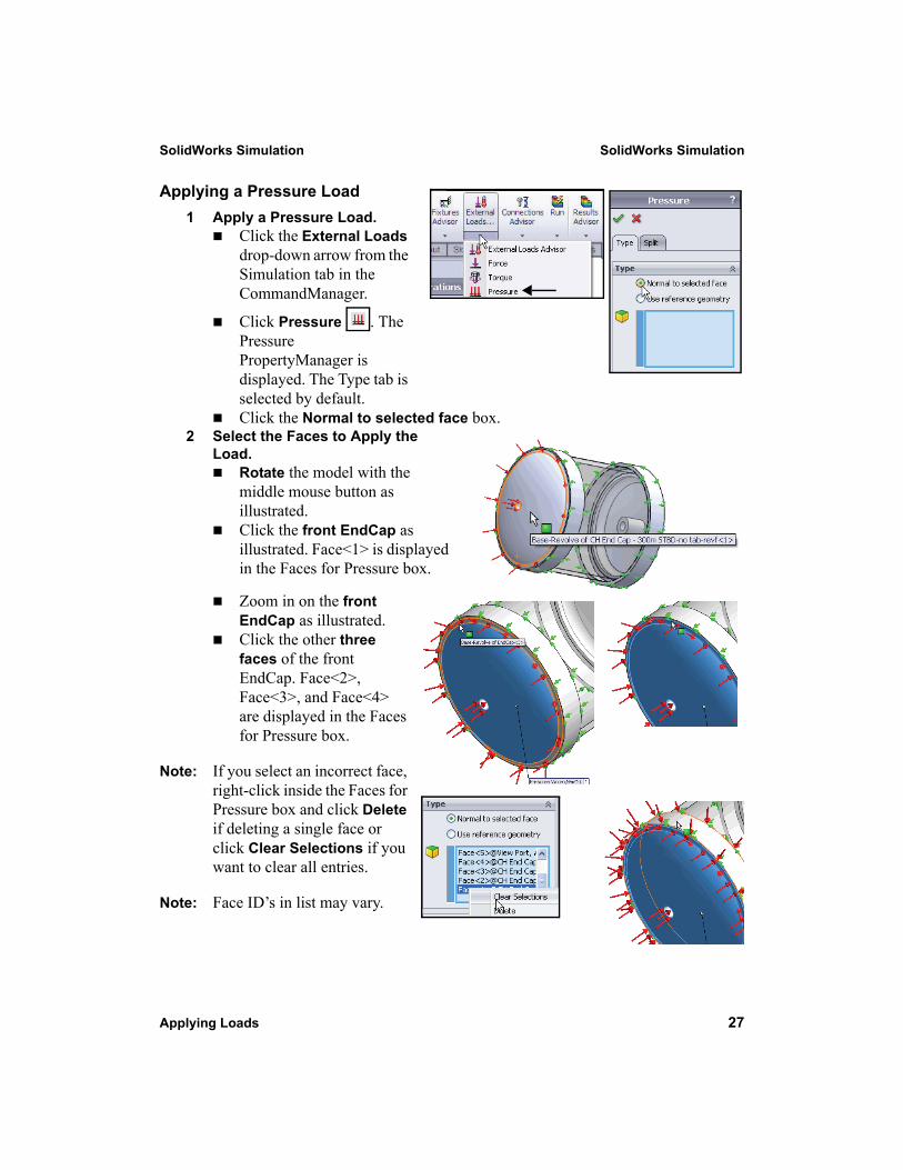
Applying a Pressure Load1 Apply a Pressure Load.
Click the External Loads drop-down arrow from the Simulation tab in the CommandManager.
Click Pressure . The Pressure PropertyManager is displayed. The Type tab is selected by default.Click the Normal to selected face box.
2 Select the Faces to Apply the Load.
Rotate the model with the middle mouse button as illustrated.Click the front EndCap as illustrated. Face<1> is displayed in the Faces for Pressure box.
Zoom in on the front EndCap as illustrated.Click the other three faces of the front EndCap. Face<2>, Face<3>, and Face<4> are displayed in the Faces for Pressure box.
Note: If you select an incorrect face, right-click inside the Faces for Pressure box and click Delete if deleting a single face or click Clear Selections if you want to clear all entries.
Note: Face ID’s in list may vary.
SolidWorks Simulation SolidWorks Simulation
28 Applying Loads
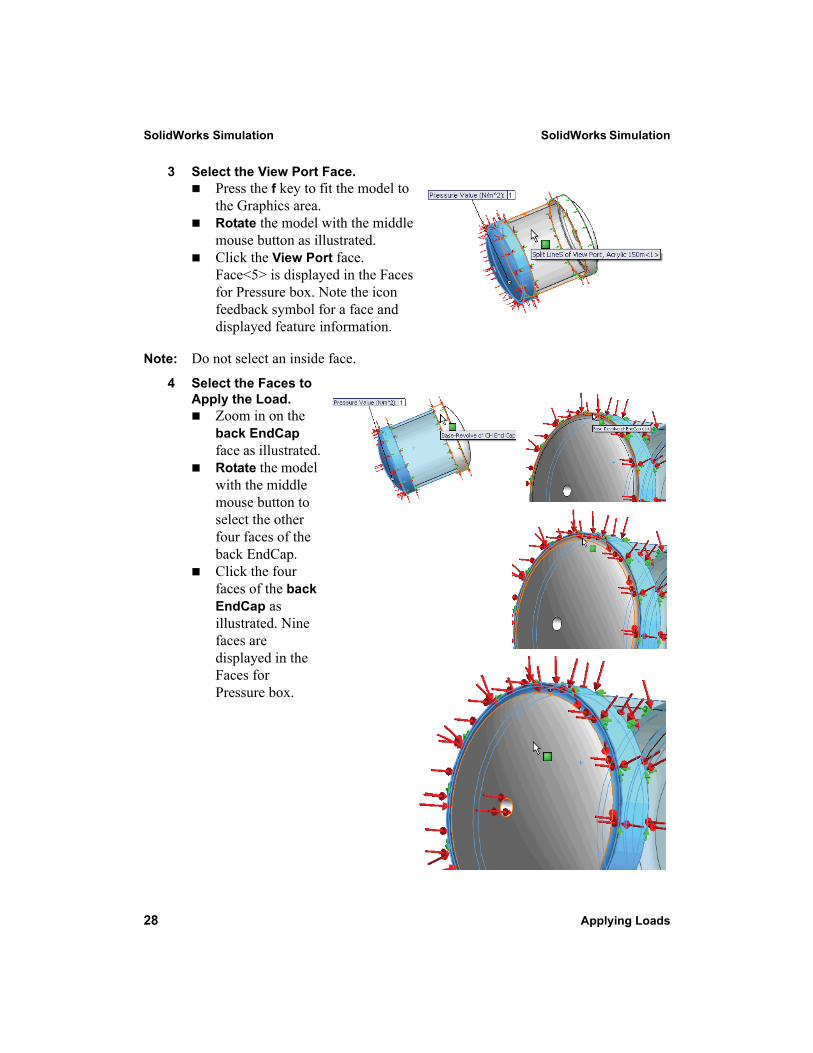
3 Select the View Port Face.Press the f key to fit the model to the Graphics area.Rotate the model with the middle mouse button as illustrated.Click the View Port face. Face<5> is displayed in the Faces for Pressure box. Note the icon feedback symbol for a face and displayed feature information.
Note: Do not select an inside face.
4 Select the Faces to Apply the Load.
Zoom in on the back EndCap face as illustrated.Rotate the model with the middle mouse button to select the other four faces of the back EndCap.Click the four faces of the back EndCap as illustrated. Nine faces are displayed in the Faces for Pressure box.
SolidWorks Simulation SolidWorks Simulation
Applying Loads 29
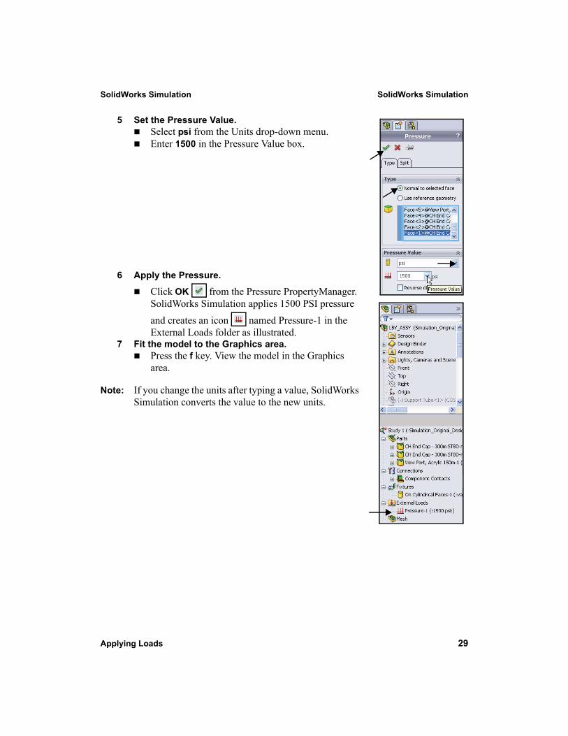
5 Set the Pressure Value.Select psi from the Units drop-down menu. Enter 1500 in the Pressure Value box.
6 Apply the Pressure.
Click OK from the Pressure PropertyManager. SolidWorks Simulation applies 1500 PSI pressure and creates an icon named Pressure-1 in the External Loads folder as illustrated.
7 Fit the model to the Graphics area.Press the f key. View the model in the Graphics area.
Note: If you change the units after typing a value, SolidWorks Simulation converts the value to the new units.
SolidWorks Simulation SolidWorks Simulation
30 Creating a Mesh and Running the Analysis
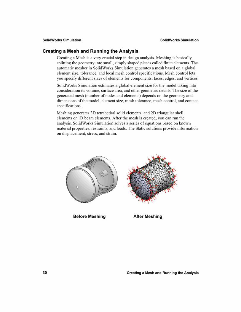
Creating a Mesh and Running the AnalysisCreating a Mesh is a very crucial step in design analysis. Meshing is basically splitting the geometry into small, simply shaped pieces called finite elements. The automatic mesher in SolidWorks Simulation generates a mesh based on a global element size, tolerance, and local mesh control specifications. Mesh control lets you specify different sizes of elements for components, faces, edges, and vertices.SolidWorks Simulation estimates a global element size for the model taking into consideration its volume, surface area, and other geometric details. The size of the generated mesh (number of nodes and elements) depends on the geometry and dimensions of the model, element size, mesh tolerance, mesh control, and contact specifications.Meshing generates 3D tetrahedral solid elements, and 2D triangular shell elements or 1D beam elements. After the mesh is created, you can run the analysis. SolidWorks Simulation solves a series of equations based on known material properties, restraints, and loads. The Static solutions provide information on displacement, stress, and strain.
Before Meshing After Meshing
SolidWorks Simulation SolidWorks Simulation
Creating a Mesh and Running the Analysis 31
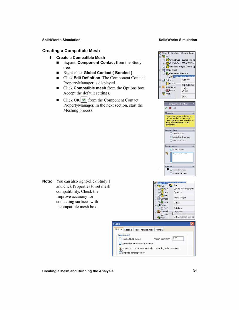
Creating a Compatible Mesh1 Create a Compatible Mesh
Expand Component Contact from the Study tree.Right-click Global Contact (-Bonded-).Click Edit Definition. The Component Contact PropertyManager is displayed.Click Compatible mesh from the Options box. Accept the default settings.Click OK from the Component Contact PropertyManager. In the next section, start the Meshing process.
Note: You can also right-click Study 1 and click Properties to set mesh compatibility. Check the Improve accuracy for contacting surfaces with incompatible mesh box.

SolidWorks Simulation SolidWorks Simulation
32 Creating a Mesh and Running the Analysis
Creating a Mesh1 Create a Mesh.
Click the Run drop-down arrow from the Simulation tab in the CommandManager. Click Create Mesh . The Mesh PropertyManager is displayed suggesting Global Size and Tolerance values.
2 Review the Meshing Options.Expand the Mesh Parameters box. View the available options.Expand the Advanced box. View the available advanced options for additional control.
SolidWorks Simulation SolidWorks Simulation
Creating a Mesh and Running the Analysis 33
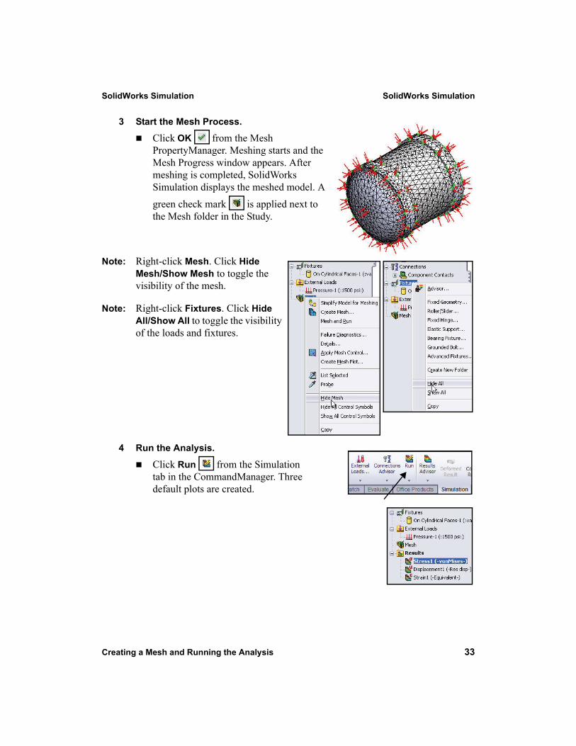
3 Start the Mesh Process.
Click OK from the Mesh PropertyManager. Meshing starts and the Mesh Progress window appears. After meshing is completed, SolidWorks Simulation displays the meshed model. A green check mark is applied next to the Mesh folder in the Study.
Note: Right-click Mesh. Click Hide Mesh/Show Mesh to toggle the visibility of the mesh.
Note: Right-click Fixtures. Click Hide All/Show All to toggle the visibility of the loads and fixtures.
4 Run the Analysis.
Click Run from the Simulation tab in the CommandManager. Three default plots are created.
SolidWorks Simulation SolidWorks Simulation
34 Viewing the Results
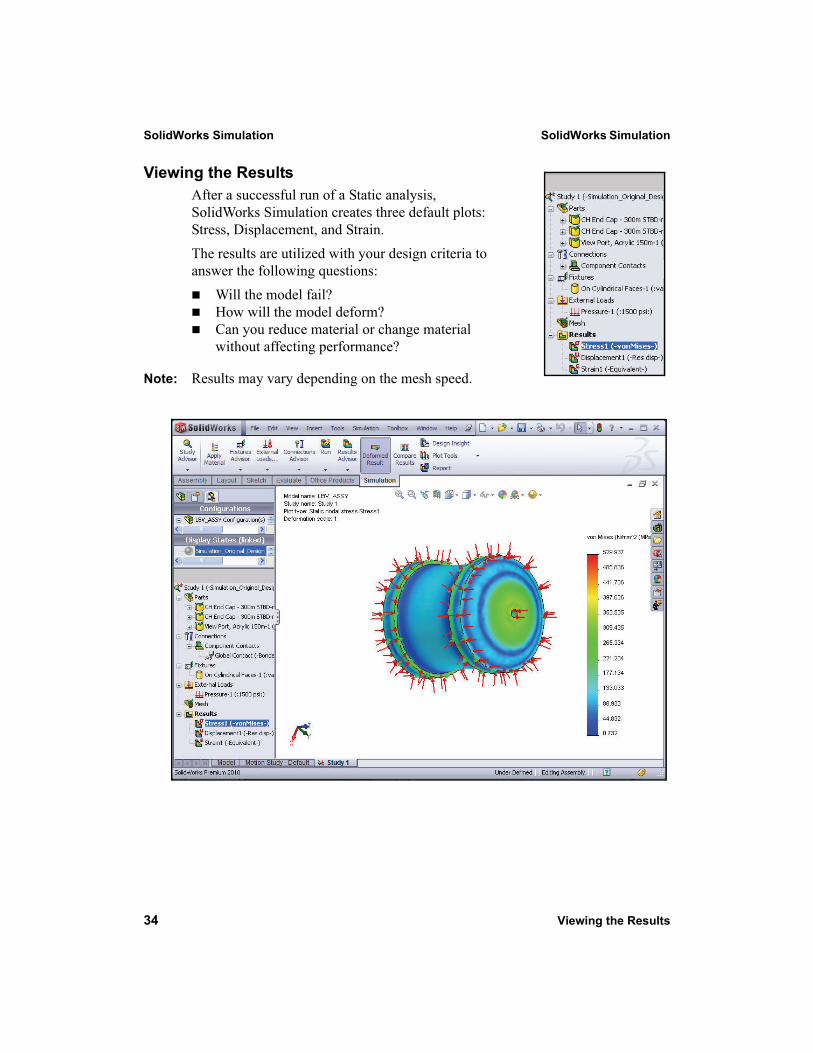
Viewing the ResultsAfter a successful run of a Static analysis, SolidWorks Simulation creates three default plots: Stress, Displacement, and Strain.The results are utilized with your design criteria to answer the following questions:
Will the model fail?How will the model deform?Can you reduce material or change material without affecting performance?
Note: Results may vary depending on the mesh speed.
SolidWorks Simulation SolidWorks Simulation
Viewing the Results 35
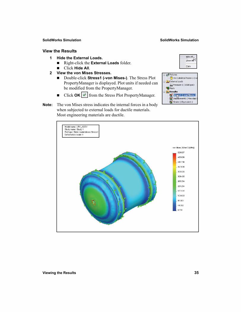
View the Results1 Hide the External Loads.
Right-click the External Loads folder.Click Hide All.
2 View the von Mises Stresses.Double-click Stress1 (-von Mises-). The Stress Plot PropertyManager is displayed. Plot units if needed can be modified from the PropertyManager.Click OK from the Stress Plot PropertyManager.
Note: The von Mises stress indicates the internal forces in a body when subjected to external loads for ductile materials. Most engineering materials are ductile.
SolidWorks Simulation SolidWorks Simulation
36 Viewing the Results
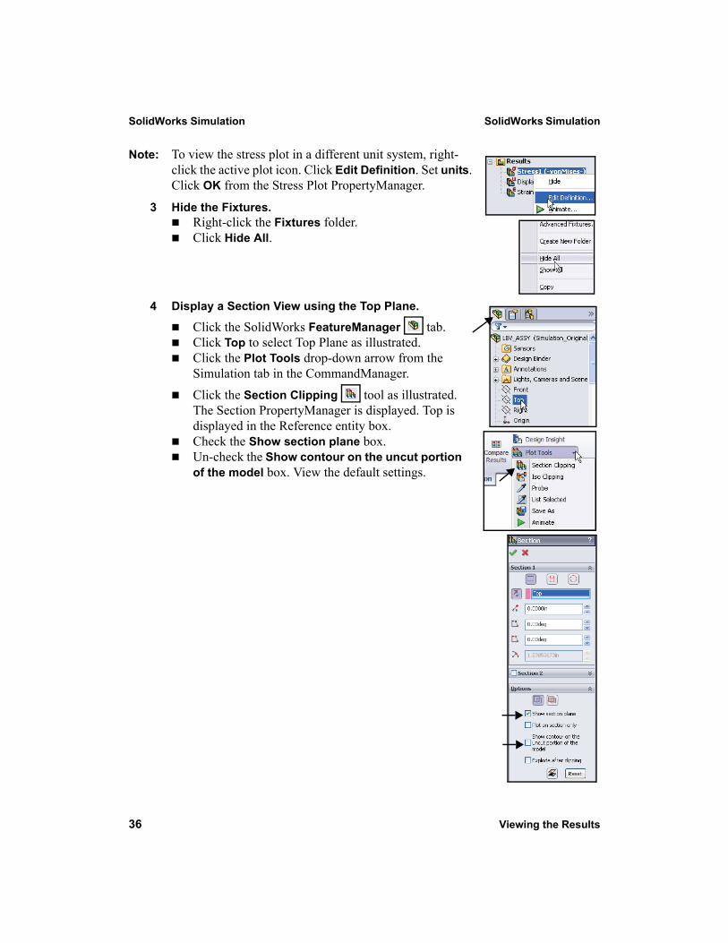
Note: To view the stress plot in a different unit system, right-click the active plot icon. Click Edit Definition. Set units. Click OK from the Stress Plot PropertyManager.
3 Hide the Fixtures.Right-click the Fixtures folder.Click Hide All.
4 Display a Section View using the Top Plane.
Click the SolidWorks FeatureManager tab. Click Top to select Top Plane as illustrated.Click the Plot Tools drop-down arrow from the Simulation tab in the CommandManager.Click the Section Clipping tool as illustrated. The Section PropertyManager is displayed. Top is displayed in the Reference entity box.Check the Show section plane box.Un-check the Show contour on the uncut portion of the model box. View the default settings.
SolidWorks Simulation SolidWorks Simulation
Viewing the Results 37
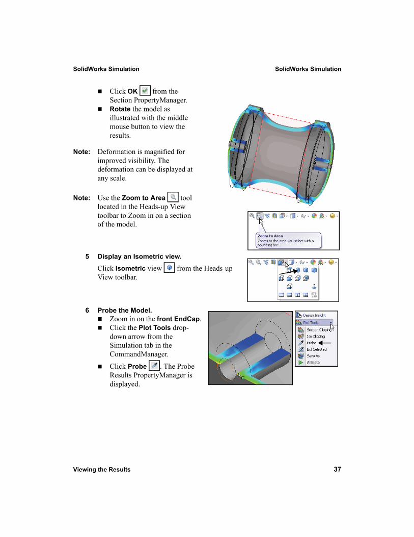
Click OK from the Section PropertyManager. Rotate the model as illustrated with the middle mouse button to view the results.
Note: Deformation is magnified for improved visibility. The deformation can be displayed at any scale.
Note: Use the Zoom to Area tool located in the Heads-up View toolbar to Zoom in on a section of the model.
5 Display an Isometric view.
Click Isometric view from the Heads-up View toolbar.
6 Probe the Model. Zoom in on the front EndCap.Click the Plot Tools drop-down arrow from the Simulation tab in the CommandManager.
Click Probe . The Probe Results PropertyManager is displayed.
SolidWorks Simulation SolidWorks Simulation
38 Viewing the Results
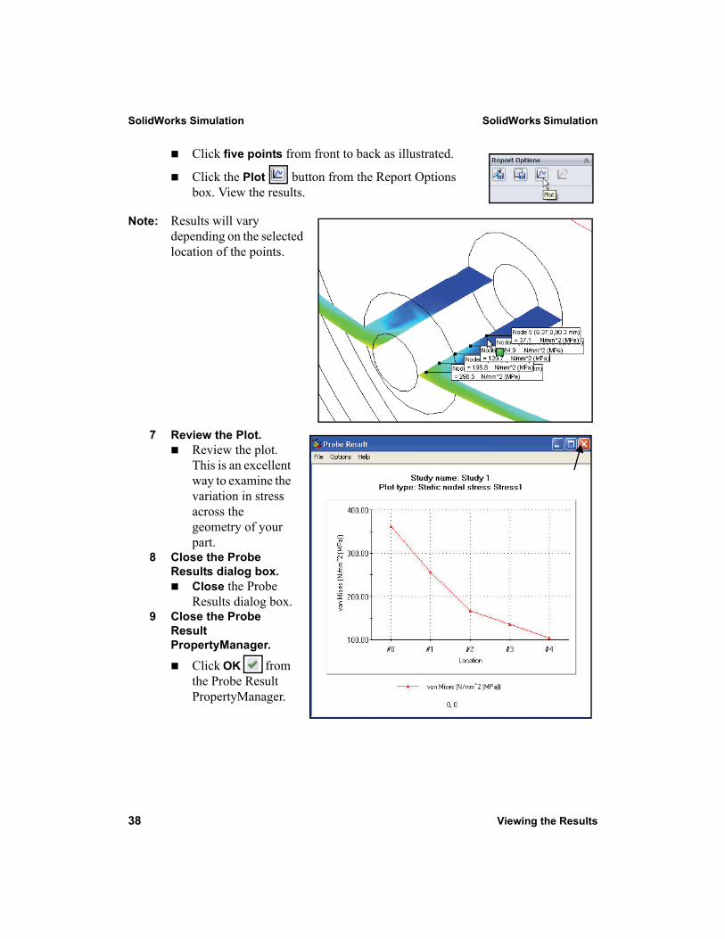
Click five points from front to back as illustrated.
Click the Plot button from the Report Options box. View the results.
Note: Results will vary depending on the selected location of the points.
7 Review the Plot.Review the plot. This is an excellent way to examine the variation in stress across the geometry of your part.
8 Close the Probe Results dialog box.
Close the Probe Results dialog box.
9 Close the Probe Result PropertyManager.
Click OK from the Probe Result PropertyManager.
SolidWorks Simulation SolidWorks Simulation
Viewing the Results 39
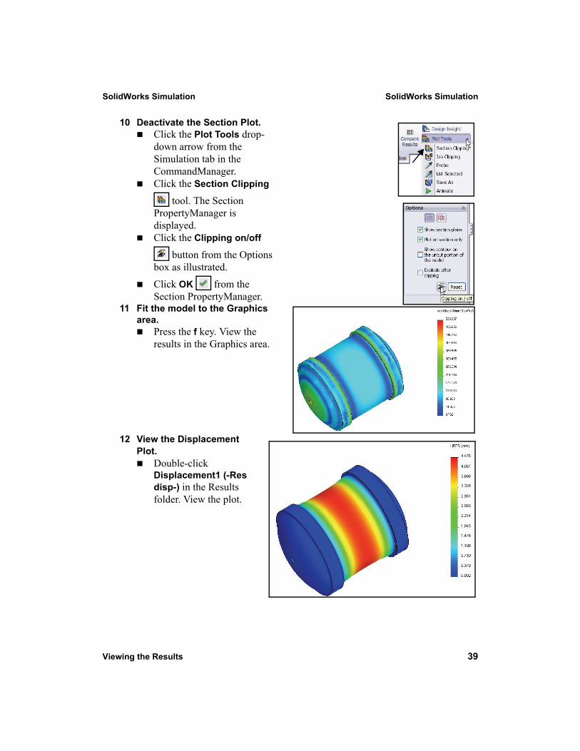
10 Deactivate the Section Plot.Click the Plot Tools drop-down arrow from the Simulation tab in the CommandManager.Click the Section Clipping
tool. The Section PropertyManager is displayed.Click the Clipping on/off
button from the Options box as illustrated.Click OK from the Section PropertyManager.
11 Fit the model to the Graphics area.
Press the f key. View the results in the Graphics area.
12 View the Displacement Plot.
Double-click Displacement1 (-Res disp-) in the Results folder. View the plot.
SolidWorks Simulation SolidWorks Simulation
Viewing the Results 41
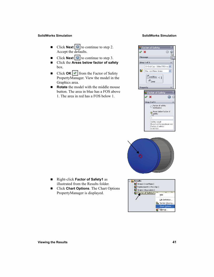
Click Next to continue to step 2. Accept the defaults.Click Next to continue to step 3.Click the Areas below factor of safety box.Click OK from the Factor of Safety PropertyManager. View the model in the Graphics area. Rotate the model with the middle mouse button. The area in blue has a FOS above 1. The area in red has a FOS below 1.
Right-click Factor of Safety1 as illustrated from the Results folder.Click Chart Options. The Chart Options PropertyManager is displayed.
SolidWorks Simulation SolidWorks Simulation
40 Viewing the Results
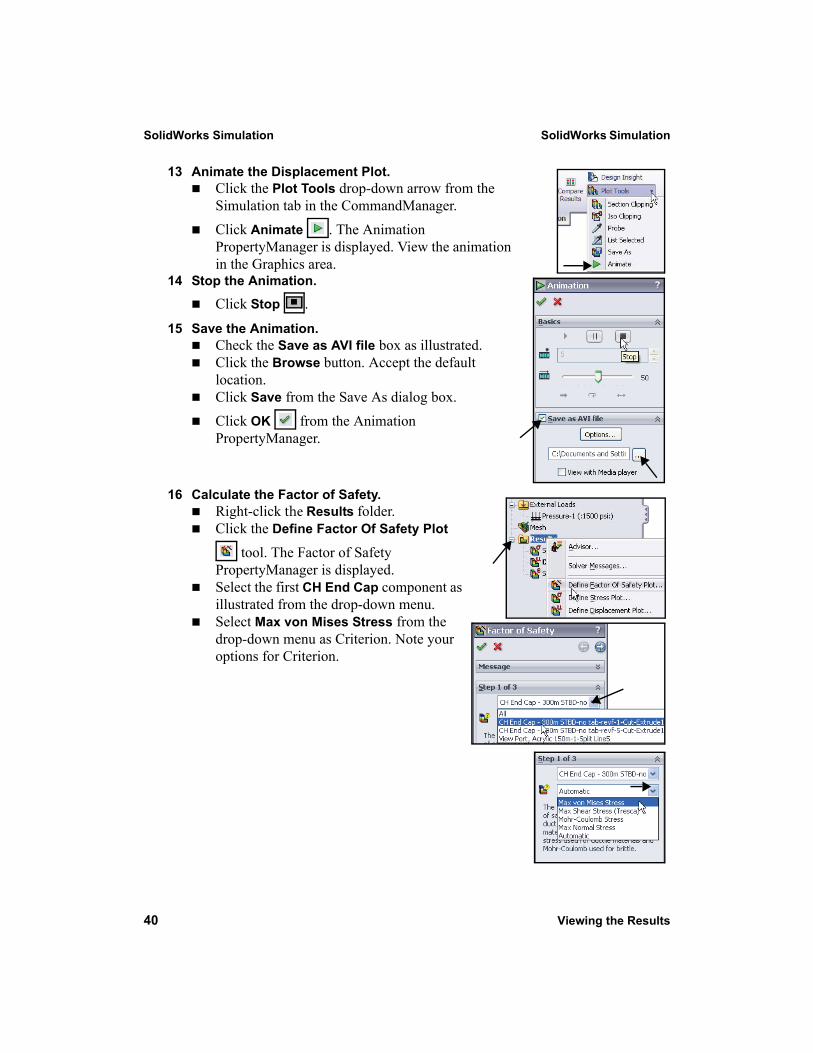
13 Animate the Displacement Plot.Click the Plot Tools drop-down arrow from the Simulation tab in the CommandManager.Click Animate . The Animation PropertyManager is displayed. View the animation in the Graphics area.
14 Stop the Animation.
Click Stop .
15 Save the Animation.Check the Save as AVI file box as illustrated. Click the Browse button. Accept the default location.Click Save from the Save As dialog box.Click OK from the Animation PropertyManager.
16 Calculate the Factor of Safety.Right-click the Results folder.Click the Define Factor Of Safety Plot
tool. The Factor of Safety PropertyManager is displayed.Select the first CH End Cap component as illustrated from the drop-down menu.Select Max von Mises Stress from the drop-down menu as Criterion. Note your options for Criterion.
SolidWorks Simulation SolidWorks Simulation
42 Viewing the Results
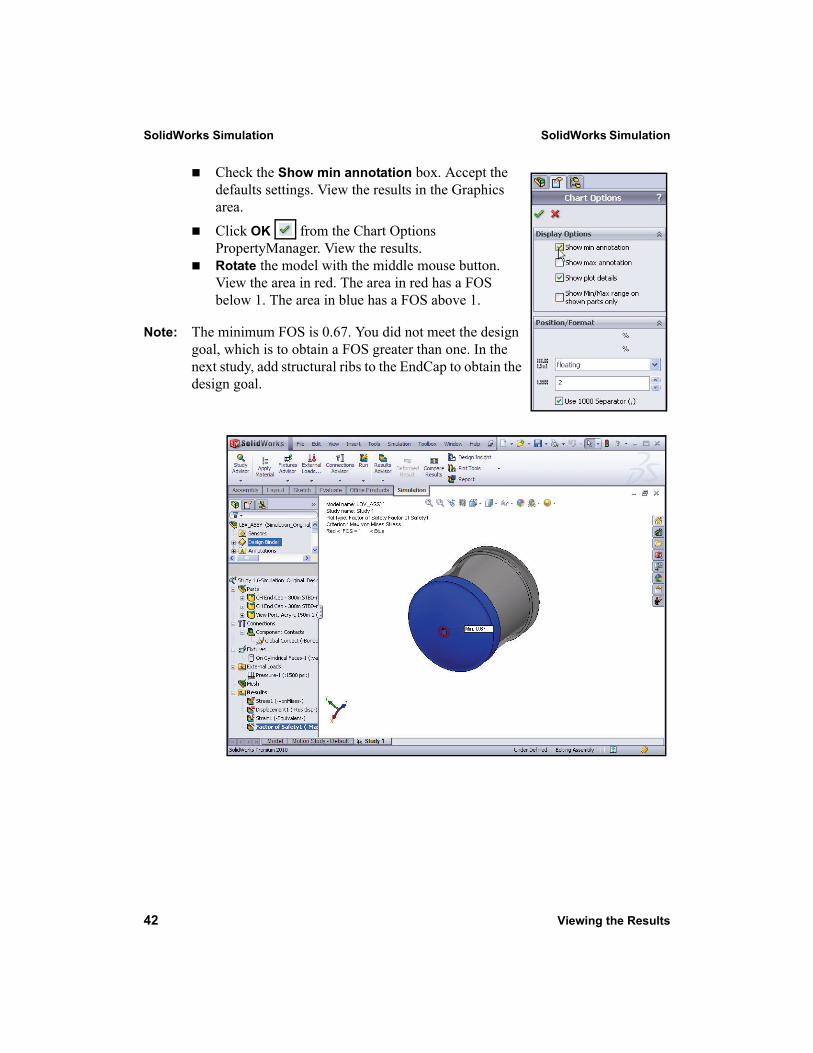
Check the Show min annotation box. Accept the defaults settings. View the results in the Graphics area.Click OK from the Chart Options PropertyManager. View the results.Rotate the model with the middle mouse button. View the area in red. The area in red has a FOS below 1. The area in blue has a FOS above 1.
Note: The minimum FOS is 0.67. You did not meet the design goal, which is to obtain a FOS greater than one. In the next study, add structural ribs to the EndCap to obtain the design goal.