soliton1/soliton jr - evneticsevnetics.com/downloads/soliton_manual_1v4_rev2.pdf · ·...
TRANSCRIPT

Soliton1/Soliton Jr 300kW/150kW Brushed DC Motor ControllerOwner's Manual
Evnetics, LLC.2027 4th Ave S
St. Petersburg, FL 33712www.evnetics.com
Manual: 1.4 rev.2 (09/09/2011)

Table of Contents1 OVERVIEW...................................................................................................................3
Soliton1/Soliton Jr Specs and Features........................................................................42 WARNINGS/SAFE PRACTICES.......................................................................................53 INSTALLATION.............................................................................................................6
Mounting & High Power Connections..........................................................................6Motor Selection...........................................................................................................7Terminal Strip (Low Voltage) Connections...................................................................8Liquid Cooling............................................................................................................10
4 WEB INTERFACE........................................................................................................12Blue Status Box.........................................................................................................14Block A Parameters ..................................................................................................14Block B Parameters...................................................................................................17Optional I/O Parameters............................................................................................19Block C Parameters...................................................................................................20Block D Parameters...................................................................................................22Throttle Calibration....................................................................................................23Updating the Controller Software..............................................................................23Data Logger...............................................................................................................24
5 OPERATION................................................................................................................26Normal Operation......................................................................................................26Error Conditions.........................................................................................................26
6 APPENDIX A – Example Wiring Diagram....................................................................277 APPENDIX B – Technical Data/Troubleshooting..........................................................28
The Basics of PWM Motor Controllers........................................................................28Derating Schedule.....................................................................................................29Ethernet Port.............................................................................................................30Troubleshooting.........................................................................................................30Technical Support......................................................................................................32
8 APPENDIX C – Warranty/Terms..................................................................................33
2

1 OVERVIEWThe Soliton1 and Soliton Jr are motor controllers specifically designed to drive brushed DC motors (more specifically, series field) in electric vehicle applications. These motor controllers employ cutting edge technology and have a vast array of unique features: the main contactor with automatic precharge is built-in, a heatsink with both liquid and fan cooling, a state-of-the-art film capacitor on the input rated for the full ripple current (one-half to as little as one-fifth is typical!), and an ethernet interface that continuously streams live performance data and allows configuring the controller with an ordinary web browser! You run Linux or MacOS? No problem. Don't have a serial port on your computer? No problem. Despite the fearsome level of technology inside the controller, it is even easier to install and use than the venerable Curtis 1231C!
There are lots of details to consider and specs to compare when choosing a motor controller for your EV, but one of the most important considerations is how long you can get peak motor current and how often? Unlike the typical “shoe-box” style controller with little intrinsic ability to shed heat, Evnetics controllers have a massive machined aluminum, fan-cooled heatsink which give them unparalleled continuous power capability even before liquid cooling – which they also feature – is used. Other controllers may deliver a higher peak current for some brief (and usually unspecified) amount of time, but none can deliver the same amount of current for as long as the Soliton1. Period.
Raw power might be great at the drag strip, but without the ability to precisely and safely control that power, everyday driving situations like rush-hour congestion or pulling into a parking space quickly turn tedious. The throttle input to Evnetics' controllers directly controls motor current for an exceptionally smooth and natural driving feel, even at low currents and 0 RPM, and without emitting an annoying whine through the use of random pulse skipping, rather than an abrupt change in switching frequency.
Unlike other companies making EV-related products, Evnetics is comprised of a core development team with interlocking and complementary expertise in mechanical engineering, power electronics and embedded software design. To put it simply: we make better products not only because we want to, but because we can...
The Evnetics Core Development TeamSebastien Bourgeois – Management/Mechanical Design
Jeffrey Jenkins – Hardware DesignMartin Persson – Software Design
3
Soliton1/Soliton Jr Specs and Features
• 9V-340V battery voltage range (output current reduced above 310V).• 1000A max current (battery or motor) for the Soliton1; 600A max current
(battery or motor) for the Soliton Jr.• Thermal derating smoothly reduces allowed current with temperature.• Main contactor and precharge/discharge control built-in!• Splash-proof (approx. IP55 rated) nickel plated aluminum enclosure.• Rugged design based on 600V industrial IGBT modules.• High reliability 600V film capacitors in the power stage – no electrolytics!• 1.5V max voltage drop at max output current (0.8V is typical).• PID loop to idle the traction motor (for A/C, automatic transmissions, etc.).• State-of-the-art laminated bus structure extracts maximum performance from
the IGBTs by reducing noise, ringing and spikes.• Full optical isolation between traction battery and 12V system.• Fully configurable with an ordinary web browser!• Performance data continuously streamed to the ethernet port.• Throttle directly controls motor current (torque) for a natural driving feel.• Motor current ramp rate can be set from 100A/s to 25kA/s.• Randomized pulse-skipping (“dithering”) maintains precise control of motor
current all the way down to 0A for smooth starts and easy low speed driving without emitting an annoying whine.
• Switching frequency selectable between 8kHz (Performance) and 14kHz (Quiet).• All low voltage connections protected against reverse polarity, spikes and treat
5V as maximum but tolerate up to 15V for convenience.• Tachometer input (1, 2, 3, 4, 6 pulses per revolution) for protecting against
overspeed and idling automatic transmissions, a/c compressors, etc. • Brake input overrides throttle when active for added safety.• Reverse input reduces max throttle and motor voltage when active.• (3) programmable inputs (analog/digital) for reverse, throttle limit, start, etc.• (3) programmable outputs for driving analog meters, cooling pump control, etc.• Error light output can directly drive the “Check Engine” light in the dash.• 3D CAD drawings of both controllers for planning installation ahead of time. • And, perhaps most importantly, we constantly strive to improve our products
and add new features and functions!
4

2 WARNINGS/SAFE PRACTICESIt takes substantial mechanical and electrical skills to be able to convert your own vehicle – if you do not possess the necessary experience (wouldn't know a volt from an amp, or an open end wrench from box head) then we strongly encourage you to seek out the services of a qualified conversion shop! If you feel you are up to the task then always keep the following in mind:
● High DC voltage can kill you! Treat anything above 60V DC as potentially lethal because it can cause muscles to lock involuntarily.
● EV-size batteries can deliver extremely high short circuit currents! They are easily capable of vaporizing a wrench, for example.
● Never ground the traction battery pack to the vehicle frame! What is okay in a 36V golf cart is not okay in a high voltage DC electric vehicle.
● Insert at least one Class T fuse into the battery pack circuit! You can insert manual disconnects and/or circuit breakers as well, but keep the fuse!
● Know and respect your motor's power limit! Most motors can tolerate maximum current or maximum voltage, but not both at the same time!
Please refer to the Limited Warranty and disclaimers of liability in Appendix C (or on our website) at the end of this document or from the support section of our website.
5
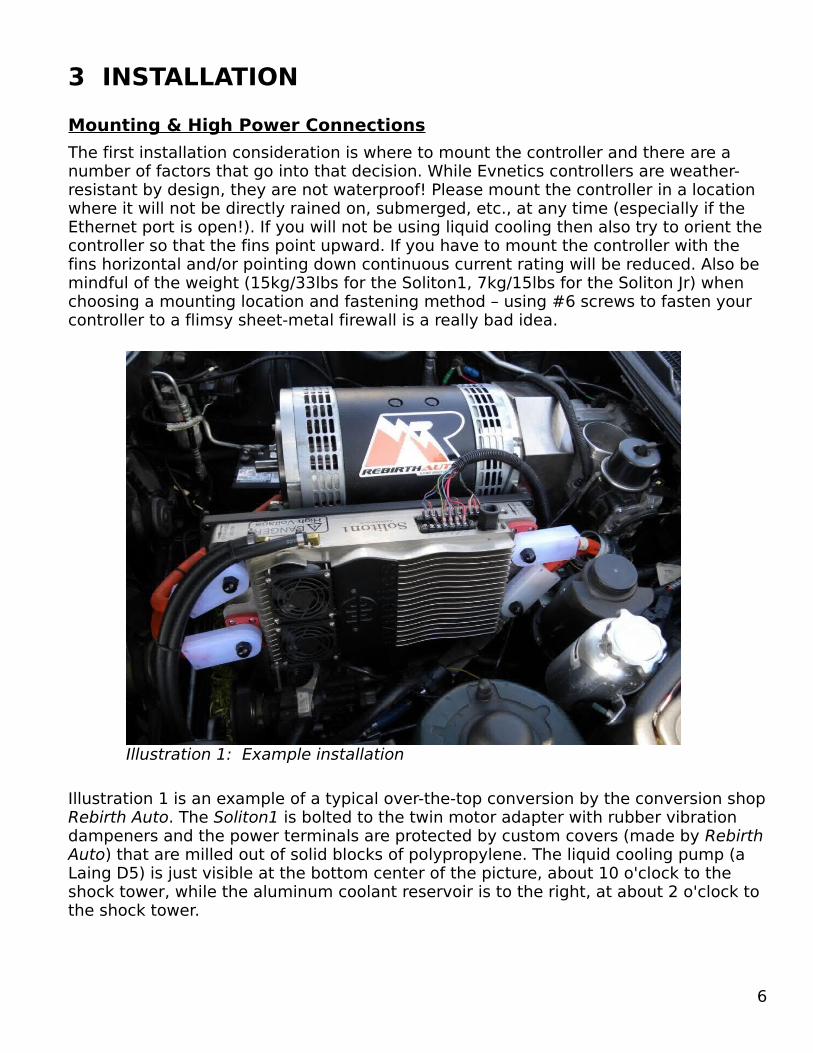
3 INSTALLATIONMounting & High Power ConnectionsThe first installation consideration is where to mount the controller and there are a number of factors that go into that decision. While Evnetics controllers are weather-resistant by design, they are not waterproof! Please mount the controller in a location where it will not be directly rained on, submerged, etc., at any time (especially if the Ethernet port is open!). If you will not be using liquid cooling then also try to orient the controller so that the fins point upward. If you have to mount the controller with the fins horizontal and/or pointing down continuous current rating will be reduced. Also be mindful of the weight (15kg/33lbs for the Soliton1, 7kg/15lbs for the Soliton Jr) when choosing a mounting location and fastening method – using #6 screws to fasten your controller to a flimsy sheet-metal firewall is a really bad idea.
Illustration 1 is an example of a typical over-the-top conversion by the conversion shop Rebirth Auto. The Soliton1 is bolted to the twin motor adapter with rubber vibration dampeners and the power terminals are protected by custom covers (made by Rebirth Auto) that are milled out of solid blocks of polypropylene. The liquid cooling pump (a Laing D5) is just visible at the bottom center of the picture, about 10 o'clock to the shock tower, while the aluminum coolant reservoir is to the right, at about 2 o'clock to the shock tower.
6
Illustration 1: Example installation
For safety and convenience there are separate battery and motor terminals on our controllers and they are not interchangeable. That is to say, there is not a straight-through connection between B+ and M+ nor B- and M- internally. The internal pack voltage monitor circuit will protect against accidentally reversing polarity on the battery connections (by refusing to close the main contactor), but accidentally connecting the battery pack to the motor terminals could result in “uncontrolled current flow” (a nice way of saying you'll blow some stuff up) so double-check all connections before applying power for the first time!
NOTE: If an additional external contactor is installed for service/emergency disconnect reasons it must be energized BEFORE the controller is turned on otherwise the controller will fault with a “No pack voltage” error.
The battery and motor terminals are 1/2”-13 studs on the Soliton1 and 3/8”-16 studs on the Soliton Jr. The battery cables are typically 2AWG to 2/0 (pronounced “two-aught” in the US) while the motor cables are typically 2/0 to 4/0. At least one Class T fuse should be in the battery circuit, mainly to protect the wiring. Keep in mind that fuses don't immediately blow as soon as their rated current is exceeded. A Mersen (formerly Ferraz-Shawmut) A50QS 250A fuse will typically pass 700A for 10 seconds, making it a good choice for Soliton Jr installations, while a A50QS 400A fuse will pass ~1500A for 10 seconds, so good for the Soliton1.
RFI and EMI (Radio Frequency and ElectroMagnetic Interference) are serious concerns in an EV because of the high voltages and currents being switched. To minimize the emission of EMI, keep the battery cables as close to each other as possible! To minimize the emission of RFI, keep the motor cables as short as possible and/or consider shielding them with metal conduit (special cable with a braided shield is made specifically for this purpose, but it is quite expensive).
NOTE: Motor controllers draw current from the battery pack in pulses (see Appendix B for a brief overview of how they work) and this causes the battery voltage to repeatedly dip and rebound. This “ripple”, as it is called, can overheat the input capacitor of a dc/dc converter (or the output capacitor of a battery charger) because it causes AC current to flow through it. This ripple can be filtered with a suitable amount of inductance – something which should have been designed into the product to begin with! A powdered-iron or MPP toroid inductor of 100uH to 470uH and rated for the continuous DC current of the device will work fine.
Motor SelectionBoth the Soliton1 and Soliton Jr controllers were designed to drive series field DC motors of 8” to 13” diameter. Series field motors have a significant amount of inductance (the popular NetGain WarP-9 is around 100uH even at 500A) which the controller relies upon to smooth out the pulses of voltage it delivers into a near-DC current through the motor. The approximate minimum amount of inductance needed by our controllers for normal operation is 10uH. Please contact us – [email protected] – if you want to use our controllers for any purpose besides driving a series field motor.
7

Terminal Strip (Low Voltage) ConnectionsAn Evnetics controller is extremely simple to wire up: the only low voltage connections that must be made are to a source of 12V (IGN) and a throttle signal. The difference in installation time compared to nearly every other motor controller is breathtaking.
CAUTION: The terminal strips on the side of the controller (See Illustration 2) are for low voltage connections only and they are totally isolated from the traction battery. NEVER APPLY PACK VOLTAGE TO ANY TERMINAL ON THESE TWO STRIPS! Do not apply more than 16V to any of the inputs or the 12V supply terminal (ie – between IGN and PGND).
Broadly speaking, the 6-terminal strip is for “power” connections while the 10-terminal strip is for “signal” connections. Please note that there are separate signal grounds (labeled SGND) on the 10-terminal strip and their use is strongly recommended to prevent picking up ground loop noise in the vehicle chassis.
INPUTS: All fixed (ie – THROT, BRAKE & TACH) and programmable (ie – IN1-3) inputs respond to a linear voltage range of 0V to +5V and are protected against negative polarity, brief spikes/overvoltage and noise. These inputs are 15V tolerant to allow being connected to 12V nominal signals – such as the brake or reverse lights – directly.
OUTPUTS: All programmable outputs (OUT1-3) are grounded when off (NOTE: the earliest hardware had floating “high-side” drivers) and deliver the nominal 12V supply when active. Current is limited to 1A peak, 500mA continuous for each output. Drive a small automotive relay with the output if you need to switch a heavy load (e.g. - coolant pump, large contactors), etc.). The output drivers are protected against inductive kickback so there is no need to put a diode across the relay coil.
Evnetics controllers require a stable source of 12V (11V to 15V) at the IGN terminal to operate (PGND is the negative connection and can be grounded to the vehicle chassis or wired to the negative post of the 12V battery). The controller does not need a separate ignition signal to turn on – orderly power up and shutdown is handled internally. While this is very convenient from an installation and operation standpoint, it does mean that a drop in the 12V supply could be interpreted as shutting down. This is desired behavior when the ignition key is turned off by the driver; it is not desired behavior if the drop is caused by the headlights or wipers turning on, etc.. Hence, we strongly recommend retaining at least a small 12V battery and a means to keep it charged (e.g. - a dc/dc converter or the OEM alternator driven off the motor's tailshaft).
8
Illustration 2: terminal strips

NOTE: The controller only draws 1A in normal operation (not including any any loads driven by the auxiliary outputs) but requires up to 8A peak to engage the main contactor(s) so please use at least 16AWG wire for the 12V power connections. If the supply voltage drops below 11V the red LED (and ERR output) will rapidly flash, and if the supply voltage drops below 10V or exceeds 15.5V for more than 10-50ms then the controller will shut down immediately, logging a fault to the error list on the web interface page (and to logger.txt if logger is running).
THROTTLE: The throttle input on Evnetics' controllers responds to a 0-5V signal so it is compatible with a wider range of transducers than the traditional 0-5k resistance input. You can use a potentiometer (pot), Hall effect pedal assembly (HEPA), etc., or even the signal from the OEM throttle position sensor (TPS) for a throttle, the only requirement is that the voltage be directly proportional to throttle position (not inversely proportional, that is) and fall within the range of 0-5V. A regulated/protected source of 5V is provided for the throttle at the S5V terminal. If using our Throttle Assembly (see Illustration 3), then connect the full throttle end (red wire) to the S5V terminal, the zero throttle end (black/shield wires) to SGND and the wiper (white wire) to THROT.
NOTE: OEM throttle position sensors usually have two channels where one is either a fixed percentage of the other (ie – Ch1 is 0-5V while Ch2 is 0-2.5V) or is inversely proportional to the other (ie – Ch1 is 0-5V while Ch2 is 5-0V). The inverted channel cannot be used! Once you have identified the wire carrying the throttle signal simply splice another wire to it to feed the THROT which you will need to identify the wire with the but be aware that calibrating the throttle (explained later) might be difficult. Also note that if the wiring run between the throttle transducer and the controller is longer than 1m (~3') then consider the use of shielded cable, such as Radio Shack part # 278-0513, and connect the shield to SGND.
CAUTION: While the popular Curtis PB-6 “pot box” can be adapted to work with Evnetics' controllers, we don't really recommend it because the potentiometer is of such low quality (sorry Curtis!).
The other terminals do not need to be connected for the controller to function, but they can greatly enhance the utility and safety of an EV if used.
BRAKE: inhibits motor current whenever active regardless of throttle signal (unless the throttle is returned to zero then reapplied while brake is active the entire time – to facilitate burnouts). Can be set to active high or low. Does not affect idle.
IN1-3: programmable inputs, current selections are “Throttle Limit”, “Reverse” and “Start” (0-5V analog signal range and tolerant of up to 15V). Adjacent check box for “Invert” flips the polarity from active high to active low (ie – ground to activate). Note that all inputs are weakly grounded internally (described in more detail later).
9
Illustration 3: Evnetics throttle

OUT1-3: programmable outputs for driving meters, contactors, relays, lights, etc., as long the device runs on 12V nominal and uses less than 1A peak, 500mA continuous (each).
TACHOMETER – this input accepts pulses (peak amplitude of 4V to 15V) from a wide variety of transducers to read the motor RPM (overspeed protection and idle can't work without it). We use an industrial inductive proximity (“prox”) sensor on our dyno (Illustration 4) and recommend it highly. This type of sensor usually has an “open collector” (OC) output, either PNP (which requires a resistor to ground, called a “pulldown”) or NPN (which requires a resistor to the positive supply, called a “pullup”). The resistor is typically 1k, but can be as low as 220Ω to as high as 3.3k (going higher is possible, but can result in increased noise pickup).
Other sensors can be used for tach (e.g. - optical, Hall effect, capacitive, etc.), but we prefer the inductive type because it is naturally immune to stray magnetic fields, is unaffected by dirt/moisture, and can detect differences in metal – such as a stainless steel bolt head in a ferrous shaft coupler - rather than needing a magnet or ferrous target in a non-ferrous material like a Hall effect sensor.
Liquid CoolingEvnetics controllers feature a liquid cooling loop that passes directly underneath the active semiconductors to provide maximum heat removal efficiency. Despite having a beefy finned heatsink and fans, we highly recommend using liquid cooling if only because every 10C drop in temperature doubles the life of electronic components.
Only use a 50/50 mix of water and aluminum-safe antifreeze for coolant. A flow rate of 1-2 GPM (4-7 LPM) is sufficient and system pressure should be 20 PSI or less. The plastic version of the Laing D5 pump works well and is reasonably priced. Transmission
coolers available at most auto-parts stores make excellent heat exchangers. It is
10
Illustration 4: tach sensor on our dyno
Illustration 5: liquid cooling connections on the Soliton1

highly recommended that a reserve tank be used to store the coolant to accommodate expansion and provide an easy means of releasing any air trapped in the system. A typical installation is shown in Illustration 1 on page 6.
The coolant ports (Soliton1 shown in Illustration 5) are tapped 1/8”-27 NPT. Brass or plastic tubing adapters with pipe dope or Teflon tape on the threads is recommended.
NOTE: The coolant ports on the Soliton Jr are, unfortunately, much closer together than on the Soliton1 so you will have to use straight tubing adapters as a result.
11

4 WEB INTERFACEThe user interface for our controllers is exceptionally intuitive: an ordinary looking web page! You can access this web page (which we usually refer to as the web interface) with any computer (laptop, typically) that has an ethernet port and can run a web browser; in other words, any computer made after 1996.
For Microsoft Windows ® Windows plays fast and loose with TCP/IP, especially with the way it automatically assigns an IP address to a new device on its local LAN. This typically results in having to wait 30 seconds to 1 minute before you can access the controller's web interface after connecting to it with an ethernet cable. At any rate, enter http://169.254.0.1/ into your web browser's address bar (bookmark it for later use) to connect to the controller. If your browser displays a “404” error it's probably because you didn't wait long enough – just click on the “Try Again” button or refresh the page. If you still can't reach the controller's web page try running our data logging program, “logger” (see page 24), as it uses a different communication protocol – if logger works but the web page doesn't then anti-virus or firewall software is almost certainly the problem – please disable any such programs and try again.
For all other OS (Linux, MacOS, etc.) or if Windows' DHCP is disabledIn contrast, you will have to make some changes to the network configuration if using a non-Windows OS or have disabled DHCP in Windows. First note your laptop's current settings for IP address and netmask because changing these could prevent the computer from accessing other networks, including the internet, then change the computer's IP address to 169.254.0.2 and the netmask to 255.255.0.0 – the gateway and DNS server fields should have nothing entered into them but if there is, then note those entries and clear them out. Now connect the controller and laptop together with an ethernet cable and enter http://169.254.0.1 into your web browser's address bar.
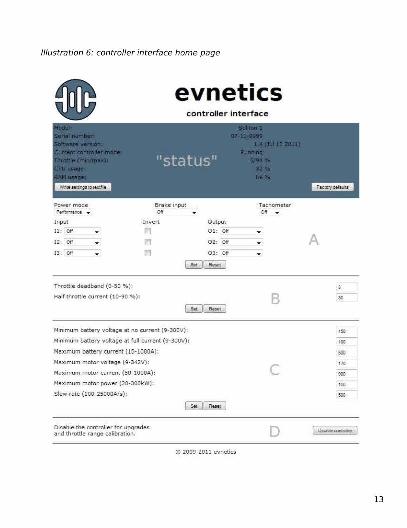
Once you have successfully connected to the controller you will see a web page similar to that in Illustration 6 (minus the word “status” and the letters A-D which were added to make it easier to explain each section). As new functions are added to the software this page will change and this manual will be updated. The latest standard version of the controller code and this manual can be downloaded from the support section of our website.
NOTE: There is a bug in the ethernet interface chip that occasionally causes it to hang, particularly if you try to scroll down the web page while it is in the process of being refreshed. The rest of the controller isn't affected but you have to cycle power to reset the ethernet chip. In the meantime, just be sure to let the page finish loading after changing a setting.
CAUTION: Do not change any settings while throttle is applied as any setting which affects controller operation will immediately cut motor output to zero then automatically ramp back up at the user-specified ramp rate!
12
13
Illustration 6: controller interface home page

Blue Status BoxBasic information about the controller is reported in the blue status box.
• Model: Soliton 1 or Soliton Junior• Serial number: in the format MM-YY-xxxx• Software version: latest version for which this manual covers is 1.4• Current controller mode: see Appendix B for a list of modes• Throttle (min/max): percent of 5V supply considered zero and full throttle• CPU usage: percent load of CPU – mainly for diagnostic purposes• RAM usage: percent of operating memory in use – as above
Write settings to textfile: This button will create a text file called “settings.txt” in your computer's default “Downloads” directory. Should you need technical support you will almost certainly be asked to send this file to us. It's also a handy way of backing up your settings should you accidentally press the other button, Factory defaults.
Factory defaults: This button resets all parameters to their factory defaults.
If an error has been recorded a, uh..., pink error list will show up in the web interface. The last 16 errors are recorded to non-volatile memory so they will persist until cleared. See the troubleshooting section of Appendix B (on page 30) for more details.
Block A Parameters In this block you configure the behavior of the fixed and programmable inputs and outputs on the controller.
Power Mode – Selects between a switching frequency of 8kHz (Performance) or 14kHz (Quiet). Switching losses and EMI are lower in Performance mode while ripple voltage and, of course, motor noise are lower in Quiet mode. Performance mode should be used unless you can hear the motor “singing” and/or you are running a battery pack voltage below ~120V. Note that at high current and/or high heatsink temperature the switching frequency reverts back to 8kHz despite Quiet mode being selected.
14
Illustration 7: Block A parameters - inputs

Brake input – when active (high or low) this function immediately reduces motor current to zero, regardless of the throttle setting. Recognizing man's eternal love of burnouts, you will be able to reapply throttle if you first let it go to zero while keeping the brake applied the entire time.
Tachometer – selects the number of pulses per turn (1, 2, 3, 4, 6, 8) for the RPM sensor. Best results will be obtained with 1, 2 and 3 ppt because the noise filtering in both hardware and software restricts the resolution and range of the RPM reading (e.g. - 4250 RPM for 6 ppt and 3750 RPM for 8 ppt). It probably goes without saying, but an RPM sensor must be installed and configured properly for the overspeed protection and idle functions to work.
Inputs 1-3 – Programmable inputs that can, thus far, be configured as “Throttle Limit”, “Reverse” and “Start”. Checking the invert box flips the active polarity so that grounding the input activates it (note that the inputs are already weakly grounded so a pullup resistor will be needed).
• Throttle Limit – restricts throttle to a programmed percentage of maximum (0-100%) when active. The input field for this function appears in Block B. If set to 0% then it will also cancel idle when active. Can be used as an ad hoc valet mode, to reduce power when the motor temperature switch trips or a BMS indicates a cell has hit its LVC, etc.
• Reverse – used to limit motor voltage and percent throttle when driving in reverse (whether electrically, via contactors, or from shifting the transmission into reverse). Input fields for this function appear in Block B.
• Start – used in conjunction with the “Run” output, a switch connected to this input can be used to enable throttle and/or idle the motor.
Outputs 1-3 – Programmable outputs which can drive meters, lights, relays, etc.
15
Illustration 8: Block A parameters - outputs

Gauge drivers - The first five functions are “gauge drivers” and are mostly self-explanatory. The one for “Battery Voltage” is a bit unusual in that it is an expanded range voltmeter - you can specify both a starting and ending voltage (input fields will be in Block B).NOTE: The output driver circuit wasn't really meant to generate a linear voltage so one is approximated by varying the duty cycle of a 60Hz square wave from 0-100% (in rather coarse 2% steps). The circuit in Illustration 9 shows how to drive an ammeter which usually requires 50mV full scale; voltmeters will likely not need R2.
Select values for R1 and R2 to divide the output voltage from the controller to match the full scale reading of the meter according to this equation:
Vout = Vin * (R2 / (R1 + R2)R3/Z1 are an optional clamp that will improve accuracy by clipping the peak voltage to a consistent 5.1V (R1/R2 then need to be rescaled for 5.1V, rather than ~12-13V). For example, if R3/Z1 are used and the meter is 50mV full scale then you could use 2.2k for R1 and 22Ω for R2. For a 200mV digital panel meter, with R3/Z1 present, you could use 22k for R1, 9.1k for R2 paralleled by 1uF.
RPM (tach) – this output function can convert the actual number of pulses per turn (ppt) sent to the controller to a different number of ppt to drive a standard ICE tachometer. This means you can, for example, have a 1 ppt signal going to the controller but drive a tachometer meant for a 6 cyl. engine (3 ppt).
Run indicator – this is typically used in conjunction with the Start input. A light connected to this output will blink while the controller is waiting for the start button to be pressed then turn solid when the controller is active.
16
Illustration 9: Driving a standard ammeter

Water pump - this output goes high at 40C and low again at 35C, mimicking the behavior of the cooling fans. As the outputs are current-limited you should use a small automotive “cube” relay to switch power to the pump.
Block B ParametersThese settings are mainly influenced by choices in Block A. Enabling Throttle Limit, Battery Voltage, and RPM (tach) functions
Throttle deadband (0-50%) - specifies how much throttle voltage from the calibrated zero point is still treated as zero. This is mainly used to compensate for Hall effect pedals that tend to drift with temperature but specifying up to 5% deadband won't hurt unless the active range for your throttle is exceptionally narrow (e.g. - the calibration values displayed in the blue status box are 30/55%).
Half throttle current (10-90%) - specifies what percent of the maximum motor current the controller will attempt to deliver when the throttle is at its calibrated midpoint (in voltage output). The default is 50% - half current is delivered at half throttle – but shifting this percentage downward can approximate a logarithmic throttle response (which will improve low-speed maneuverability).
Maximum motor speed (2,000 to 8,000 RPM) – Only present if tachometer is enabled, this cuts motor current at the specified RPM to protect against overspeed (note that it can only cut current once this speed is reached, so some overshoot of RPM will occur,
17
Illustration 10: Block B parameters

especially if the motor is lightly loaded). Typical limits are 5500-6000 for a 9” motor, 4500-5000 for an 11” motor and 4000 for a 13” motor ,but please check with the motor manufacturer for the actual safe RPM the motor can withstand.
Idle Parameters
Evnetics controllers have a thus-far unique ability to safely idle the electric motor in an EV, making it much easier to use an automatic transmission, as well as accessories like power steering and air-conditioning (even the alternator). It also makes it easy to break in new motor brushes – just set to 1000 RPM and run the motor for 8-12 hours.
Idle utilizes a traditional Proportional, Integral, Derivative, or “PID”, control loop to maintain a set RPM whether the load changes slowly (e.g. - as the transmission fluid heats up to operating temperature), quickly (e.g. - from the power steering pump) or abruptly (e.g. - the a/c compressor kicking on). Regulating motor speed requires a speed sensor be installed, of course, and best results are obtained with sensors that produce 2 pulses per turn. For safety reasons, Evnetics controllers will not automatically begin idling the motor – you must either apply enough throttle to bring the motor up to the idle RPM setting or press and hold the Start button (if enabled). Additionally, if Start is used to idle the motor then the motor current will ramp up at a fixed 100A/s and 100 RPM must been seen by the time 300A is reached. These precautions are necessary because an electric motor will happily produce torque all the way down to 0 rpm, whereas an IC engine in the same situation will stall, so if idle were to be engaged with a manual transmission that is in gear the car could/will start moving! A final safety feature of idle is that motor current is limited to 400A – this is sufficient to respond quickly to abrupt load changes, but much more than is typically needed to maintain a steady RPM.
Idle motor speed (0, 500-2500 RPM) – Only present if tachometer is enabled, 0 disables idle, otherwise, set to between 500 and 2500 RPM. Most modern vehicles idle at 600-800 rpm but the extended RPM range allows “off label” usage of the idle loop to control, e.g., hydraulic pumps and such. Note that there will always be some error between the actual and set idle RPM.
Idle motor max current (0-400A) – self-explanatory; only present if tachometer is enabled. Setting this too low may make it difficult or impossible for the controller to respond to changes in load or even to idle the motor in the first place.
PID Loop ParametersThese settings affect the responsiveness of the idle speed regulation loop which also affects its stability. Inappropriate settings here could cause the motor RPM to oscillate like crazy. In our experience you rarely need to change any setting by more than 5.
P – Default setting is 30. This sets the proportional gain for the loop. Increasing this will reduce short term error (from moderate load changes, for example) but will reduce stability (ie – can cause overshoot and oscillation).
18

I – Default setting is 20. The integral gain attempts to correct the steady state rpm error. This is a relatively benign parameter to increase but too much I, especially with too much P, will result in hunting, or oscillation about the setpoint.
D – Default setting is 30. The derivative gain controls how quickly the loop reacts to abrupt changes in RPM. This parameter is the most dangerous of the three to increase. The best way to test changes to this parameter is to cycle the A/C compressor.
Optional I/O ParametersThese settings will appear only if the relevant input or output function is enabled, otherwise they won't be appear.
Throttle Limit [1, 2, 3] – when active, limits maximum throttle to the percentage specified. More than one input can be configured as a throttle limit and if more than one is active at any given time the one with the lowest percentage wins. If a throttle limit is set to 0% then throttle will be totally blocked when active but idle, if active, will also be canceled.
Maximum motor voltage at reverse (9 - 342V) – when an input is configured as Reverse this entry field lets you set an alternate limit for motor voltage both to reduce top speed and prevent flashover of an advanced timing motor.
Maximum throttle at reverse (10–100 %) - this entry field also appears when an input is configured as Reverse, but this one limits the maximum throttle to the specified percentage.
Minimum gauge voltage (9-342V) – sets the battery pack voltage at or below which will register as 0% for the Battery voltage gauge driver output function.
Maximum gauge voltage (9-342V) – sets the battery pack voltage at or above which will register as 100% for the Battery voltage gauge driver output function.
19

Block C ParametersThese are the “basic” operational parameters for the controller which will almost certainly need to be changed for your particular installation.
Minimum Battery Voltage Protection
The first three settings in Illustration 11 form a powerful and unique (patent pending, actually) function for protecting the traction battery from overdischarge while still allowing for sag when pulling high currents.
Prior to version 1.4 there was a single minimum battery voltage setting which applied regardless of the reason. The new approach adopted in 1.4 is to let you specify a minimum battery voltage that must be present even when no current is being drawn (to protect against overdischarge), and a second voltage which the pack is allowed to sag down to at maximum current.
Illustration 12 shows an example of how this function calculates the allowed minimum voltage for the battery current drawn. For this example, the battery pack is nearly depleted when it has dropped to 150V, but because the battery voltage can also drop because of high current (in this example, limited to 500A), a single minimum pack voltage setting would have to compromise between overdischarging the pack – by setting it below 150V – or else unduly restricting power output – by setting it too high, thereby disallowing sag. Imagine the pack is at 160V and supplying 100A to the controller while cruising on the interstate. If the throttle is then floored to pass another car then pack current will start climbing and voltage will start dropping (both from internal resistance and depletion of capacity). Let's say that current peaks out at 400A – as long as the voltage stays above 110V, no limiting will occur. As the pack is depleted, however, it won't be able to stay above 110V at 400A so the controller will cut back on motor current until the intersection of battery current and battery voltage once again fall on the plotted line.
20
Illustration 11: Block C parameters

With this in mind you can then make rational choices for the following two voltage settings given a maximum current from your battery pack.
Minimum battery voltage at no current (9-300V) – Set this to the voltage your pack will be at when it is nearly discharged (10.5V to 11.0V per lead-acid battery, 2.8V-3.0V per LFP cell, etc.). Setting this voltage too high will rob you of usable energy capacity or even block throttle unnecessarily.
Minimum battery voltage at full current (9-300V) – Set this to the voltage you want to let the pack sag down to at the maximum allowed battery current. Keep in mind that the laws of physics state that maximum power from a battery occurs when it has sagged to half its nominal voltage, so there is no sense in going lower.
Maximum battery current (10-1000A) – Set this to the maximum current the manufacturer of your cells recommends (normally given as a multiple of the Amp-hour capacity, “C”). For example, CALB recommends 4C so a 100Ah pack should be limited to 400A (note that battery current can never be higher than motor current – see Appendix B for a brief overview of how PWM motor controllers work).
Maximum motor voltage (9V to 340V) – RPM is roughly proportional to voltage in a motor, but the commutator in a motor has both a mechanical RPM limit as well as an “electrical” one (typically 15-30V per commutator segment). This limit will let you use a higher battery pack voltage than the voltage the motor can tolerate (e.g. - 170V for a NetGain WarP-9® motor) by limiting the maximum duty times the actual battery voltage at any given time. This can help prevent excessive brush arcing or even flashover (colloquially called “zorching”).
Maximum motor current (50A to 600A or 1000A) – Torque is roughly proportional to current in a motor but losses are proportional to current squared so keep that in mind before cranking it up to “11”. High quality EV-specific motors can easily take peak
21
Illustration 12: Calculated minimum battery voltage example

currents of 600A (Soliton Jr) or 1000A (Soliton1); it's when you try to run that amount of current continuously that can causes problems. Forced air cooling of the motor, especially of its commutator, can be a tremendous help here.
Maximum motor power (20kW to 300kW) - this limit works as a “sanity check” in conjunction with the other two motor limits while not unduly limiting either top speed or torque. For example, it has been reported that a WarP-9® can take a peak current of as much as 2000A and the manufacturer recommends a maximum voltage of 170V – but the peak power it can withstand is about 150kW. The default setting of 100kW is appropriate, if a little conservative for a WarP-9® motor.
WARNING – The power output of the Soliton1 (and even the Jr!) is more than capable of destroying any single motor, even when it is only air-cooled (this is a serious warning, not just advertising hype). If you set maximum motor current to 1000A then you must limit the time at full throttle!
Slew rate (100A/s to 25000A/s) - This sets the rate at which motor current will rise (but not fall) to the value commanded by the throttle position. It is in increments of 100A/s (e.g. - at 1000A/s it will take 1 second to hit 1000A if starting from 0A). The default setting of 500A/s is responsive without being jumpy, but lighter vehicles, especially with an automatic transmission (because of the torque converter), might behave more smoothly with a lower setting (e.g. - 300A/s). Be careful when exceeding slew rates of 1000A/s because the risk of damaging the drivertrain from shock-loading goes up dramatically.
Block D ParametersIn normal operation the only entry here will be a button to disable the controller to manually update the firmware or to calibrate the throttle.
Once the Disable controller button has been clicked the web page will change to look like that in Illustration 14.
Update software – Use the Browse... button enter the name/location of the text file (e.g. - controller_1_4.txt) then click the Update button to load it into the controller's temporary storage EEPROM. Note that the update procedure can take several minutes on Windows computers - see the section Updating the Controller Software for more details on the process and an alternate method for Windows systems.
22
Illustration 13: optional parameters

Throttle CalibrationYou will almost certainly have to calibrate your throttle before being able to use the controller (if the throttle signal is not at 0V at startup then the controller will block throttle until it sees the signal at or below the calibrated zero position voltage). Fortunately, the calibration process is extremely simple.
With the throttle at rest click on the Calibrate min throttle button to store the current throttle position as “zero”. Hit back to return to the home page then apply maximum throttle and click the Calibrate max throttle button to store the full throttle position. The status box will thereafter display the new percentages of the 5V reference supply that is considered zero and full throttle (e.g. - 5/94% as shown in Illustration 6 on page 13). If you experience frequent “Throttle not in zero position” errors after calibrating then you should first try try setting 5% of Throttle deadband, as described on on page 17, but if the problem persists then you likely have mechanical issues such as binding, slippage or slack in the throttle cable and/or linkages. Ideally, you should only have to calibrate the throttle once!
Updating the Controller SoftwareThere are two ways of updating the controller software: via the web interface as described above (works on all operating systems) or via the Windows-specific uploader program, named uploader_x_x.exe, where x_x is the version number. The controller
23
Illustration 14: Block D after clicking on "Disable controller"
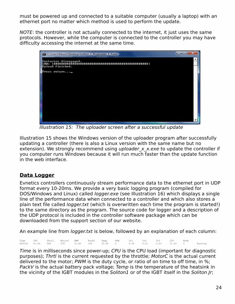
must be powered up and connected to a suitable computer (usually a laptop) with an ethernet port no matter which method is used to perform the update.
NOTE: the controller is not actually connected to the internet, it just uses the same protocols. However, while the computer is connected to the controller you may have difficulty accessing the internet at the same time.
Illustration 15 shows the Windows version of the uploader program after successfully updating a controller (there is also a Linux version with the same name but no extension). We strongly recommend using uploader_x_x.exe to update the controller if you computer runs Windows because it will run much faster than the update function in the web interface.
Data LoggerEvnetics controllers continuously stream performance data to the ethernet port in UDP format every 10-20ms. We provide a very basic logging program (compiled for DOS/Windows and Linux) called logger.exe (see Illustration 16) which displays a single line of the performance data when connected to a controller and which also stores a plain text file called logger.txt (which is overwritten each time the program is started!) to the same directory as the program. The source code for logger and a description of the UDP protocol is included in the controller software package which can be downloaded from the support section of our website.
An example line from logger.txt is below, followed by an explanation of each column:Time CPU Thrtl MotorC PWM PackV Temp RPM In1 In2 In3 12V Mode800150 41.42 580 578 31.80 148 32.40 0 0.04 0.01 0.03 11.93 5 Running
Time is in milliseconds since power-up; CPU is the CPU load (important for diagnostic purposes); Thrtl is the current requested by the throttle; MotorC is the actual current delivered to the motor; PWM is the duty cycle, or ratio of on time to off time, in %; PackV is the actual battery pack voltage; Temp is the temperature of the heatsink in the vicinity of the IGBT modules in the Soliton1 or of the IGBT itself in the Soliton Jr;
24
Illustration 15: The uploader screen after a successful update
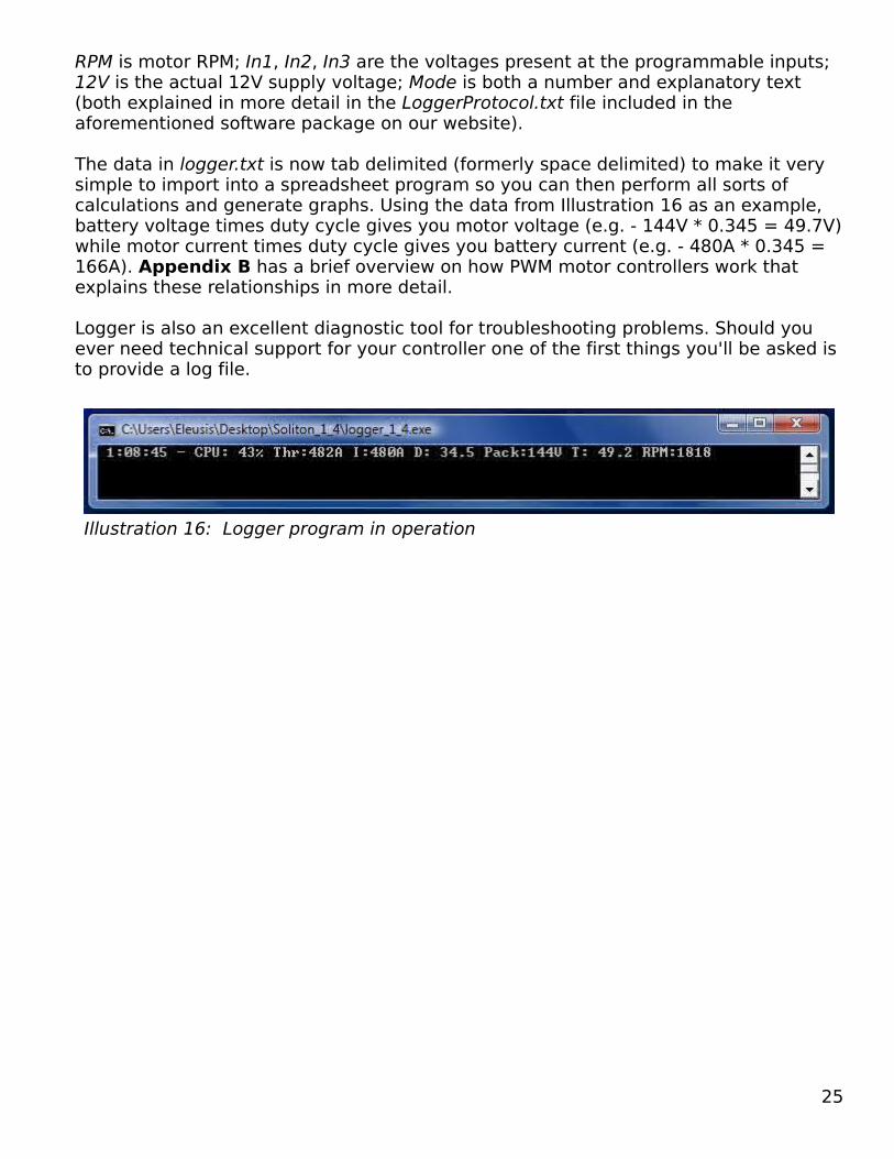
RPM is motor RPM; In1, In2, In3 are the voltages present at the programmable inputs; 12V is the actual 12V supply voltage; Mode is both a number and explanatory text (both explained in more detail in the LoggerProtocol.txt file included in the aforementioned software package on our website).
The data in logger.txt is now tab delimited (formerly space delimited) to make it very simple to import into a spreadsheet program so you can then perform all sorts of calculations and generate graphs. Using the data from Illustration 16 as an example, battery voltage times duty cycle gives you motor voltage (e.g. - 144V * 0.345 = 49.7V) while motor current times duty cycle gives you battery current (e.g. - 480A * 0.345 = 166A). Appendix B has a brief overview on how PWM motor controllers work that explains these relationships in more detail.
Logger is also an excellent diagnostic tool for troubleshooting problems. Should you ever need technical support for your controller one of the first things you'll be asked is to provide a log file.
25
Illustration 16: Logger program in operation

5 OPERATIONNormal OperationOperating an EV with an Evnetics controller is about as easy as it can get: turn the ignition switch to ON, wait for the red error LED to turn off and start driving. If the Start input is enabled then press Start to enable throttle and/or begin idling the motor.
When the controller is operating normally the green status LED will slowly cycle between lit and unlit in what we call “Cylon mode”. When the web interface is accessed the green LED will blink at a rapid and seemingly random rate to indicate data transfer. Finally, the green LED will blink rapidly immediately after startup if a new code update has been loaded – it is indicating that the code update is being error-checked and then transferred from the temporary EEPROM to the main flash memory.
Error ConditionsWe don't try to convey complex error codes with a single blinking LED; instead, we use three different blink rates - slow blink, fast blink and continuously lit – to indicate the general class of error while specifics are given in the web interface and logger output. The four broad types of errors covered by the red error LED are:
Temperature - if the heatsink is above 65C (~150F) then the error light will blink slowly (once every 2.7 seconds). The derating schedule for current vs. temperature is shown graphically in Illustration 18 in Appendix B.
RPM - the error light also blinks slowly if motor RPM limiting is in effect.
Voltage - two different errors fall under this heading, but they both cause the error light to blink quickly (3 times per second):
● Ignition (12V) voltage is below 11V (the controller is disabled at 10V)● Battery pack voltage vs. current limiting in effect (see Illustration 12)
Disabling – several errors fall under this heading all of which result in the main contactors being dropped and the error light staying on continuously:
● Ignition (12V) voltage below 10V or above 15.5V.● Traction battery pack is more than 10V below the programmed minimum voltage
at no current limit● Throttle not in zero position● Desaturation error● No pack voltage● Intentionally disabled by clicking on the “Disable controller” button.● Other errors (see TROUBLESHOOTING in Appendix B below)
26
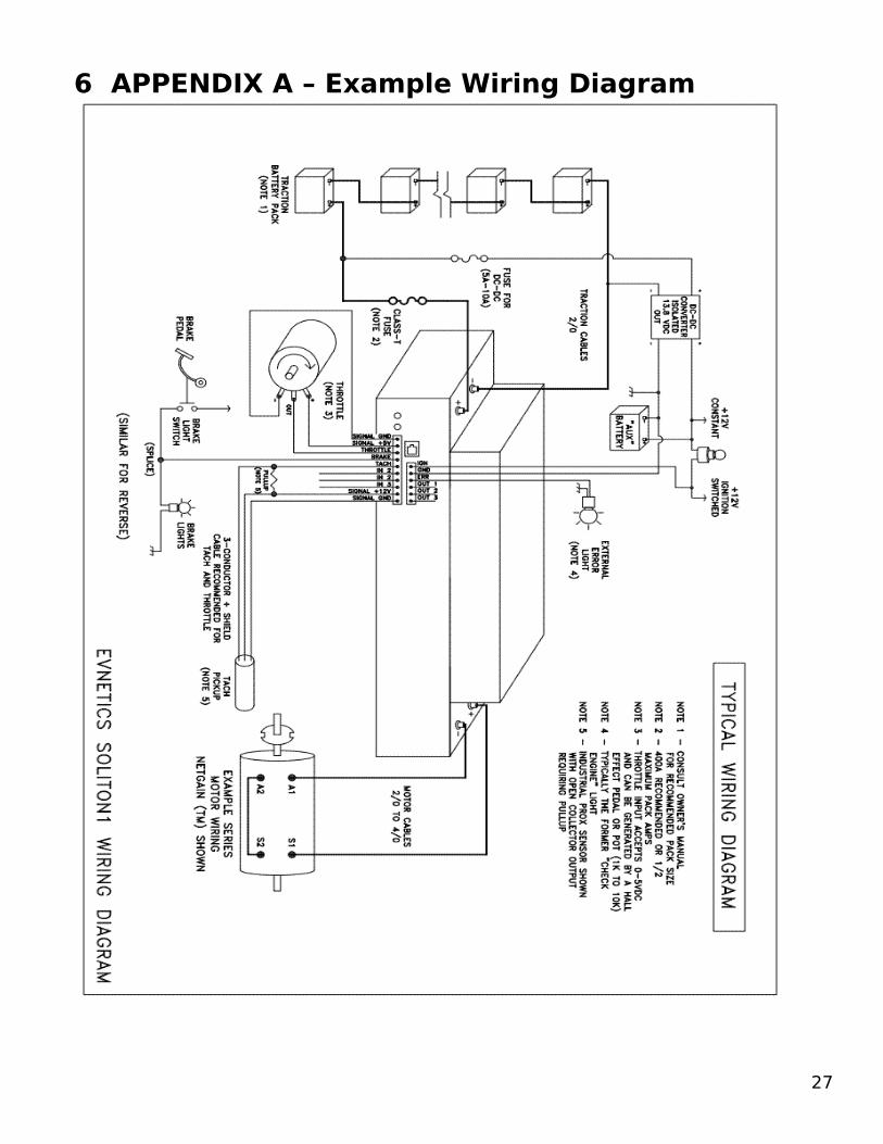
6 APPENDIX A – Example Wiring Diagram
27

7 APPENDIX B – Technical Data/TroubleshootingThe Basics of PWM Motor ControllersModern PWM motor controllers all work in essentially the same fashion – they chop up a higher battery voltage into a lower, or at most equal, motor voltage. The basic circuit used is the switchmode topology called a buck converter. Neglecting conduction and switching losses (which are typically less than 5% total in a well designed controller), the behavior of a buck converter can be described with three simple equations:
Vmotor = Vbattery * DutyImotor = Ibattery ÷ Duty
Duty = (Ton / (Ton + Toff))
Combining the first two equations shows that output power is the same as the input power. It is important to point out that motor voltage can never be higher than battery voltage and that battery current can never be higher than motor current. A simplified circuit of a motor controller is below:
When the Switch turns on current ramps up in the motor Field and Armature and when the Switch turns off the current decays through the Diode. The Cap supplies the instantaneous current need of the Switch to overcome stray inductance in the Battery pack wiring.
How this works in the real world – with a real motor - is where much misunderstanding occurs. There are some differences in the precise behavior of a series field and a PM field brushed dc motor, but, in general, both take more voltage to spin at a higher RPM and more current to deliver a higher torque. Consider what happens when you floor the throttle when the motor vehicle is at a dead stop. Maximum current flows through the motor but because it is not yet turning, the voltage needed to maintain this current is strictly the result of resistance. Once the motor begins turning, however, it will generate a voltage that opposes the flow of current through it (called “Back Electro-Mototive Force, or BEMF). As RPM increases the BEMF goes up, so to maintain a given current through the motor the controller must increase the duty cycle. When
28
Illustration 17: PWM motor controller circuit

BEMF equals the battery voltage, however, the controller can't increase the duty cycle any more – it literally runs out of voltage – and at that point motor current begins to fall. RPM will still climb, albeit at a lower rate, so the motor is then said to be in the constant power region of its operating curve. When current falls enough that the motor can no longer overcome the total losses (e.g. - from aerodynamic drag, friction, etc.) then the vehicle will have reached its top speed.
There are many interrelationships at work in an EV – far beyond the scope of this appendix – but suffice it to say that it takes more motor current to accelerate quicker, but it takes more power to go faster.
Derating ScheduleA different derating schedule for motor current vs. temperature is used for each controller because they use physically different IGBT modules. In both cases, however, if you often see the red error light blinking slowly, especially during highway driving, then consider that a strong hint to employ liquid cooling.
Technical SpecsInput voltage range: 9-342VOutput current range: 0-1000A (Soliton1); 0-600A (Soliton Jr)Input current range: 0-1000A (Soliton1); 0-600A (Soliton Jr)Max continuous power output: 300kW (Soliton1); 150kW (Soliton Jr)Current derating voltage: 310V or higher (900A for Soliton1; 500A for Soliton Jr)Minimum Load Inductance: 25uH (8kHz/300V); 10uH (14kHz/300V)Efficiency: depends on output power, but typically 98% or higherWeight: 15kg/33lb (Soliton1); 7kg/15lb (Soliton Jr)Power supply: 11V – 15V at 1A (8A peak to engage contactors)IP Rating: not formally tested, but approximately IP55EMC Rating: currently undergoing testing
29
Illustration 18: Motor current derating vs. temperature

Ethernet PortDue to a lack of supply at various times we have had to resort to using three different types of ethernet port.
Illustration 19: AmphenolPort: RJFEZ21 Plug Cover: RJFEZ6Cap: RJFEZBE
Illustration : ConecPort: 17-10020 (black); 17-10011 (metallized)Plug Cover: 17-10001 (black); 17-10013 (metallized)Cap: 17-10002 (black); 17-10014 (metallized)
Manufacturer: L-ComPort: CG-CRJPlug Cover: Only comes with portCap: Not available
TroubleshootingWe'll not try to do a comprehensive troubleshooting tree here – if you are experiencing any issues that aren't covered in this section then please contact us (details on page 32). Aside from incorrectly setting parameters, the most common problems are the result of not having a stable 12V supply for the controller. Running on either a battery or dc/dc converter alone is a recipe for disaster. The best system is a small 12V battery plus either a dc/dc converter or the OEM alternator to keep it charged.
30
Illustration 19: Amphenol
Illustration 20: Conec
Illustration 21: L-Com

The next most common issue is a low or no pack voltage error. The former is usually caused by incorrectly setting the minimum pack voltage at no load, but can also be from more ominous causes like a high resistance connection in the battery circuit or a bad cell. A no pack voltage error can be caused by not turning on an external contactor for the battery circuit before turning on the controller, or an intermittent connection in the battery circuit, or an IGBT failure preventing precharge from completing (often preceded by a desaturation error if this is the case).
One of the reasons IGBTs are so rugged is because they automatically limit short circuit current through the phenomenon called “desaturation”. A properly designed gate drive circuit for the IGBT will detect desaturation and turn it off before it is destroyed. Evnetics controllers have been tested to ensure they can survive a short circuit across the motor terminals, both when starting from 0A and when delivering max motor current at 300V input. However, desaturation is never a normal event – it takes over 1600A of current to desaturate the IGBTs in the Soliton1 - so if a desaturation error is logged but the controller operates normally after cycling the power then you should strongly suspect either a problem in the motor or its wiring, or that a “zorch” occurred, which is the colloquial term for a plasma fireball between adjacent brushes. If a single desaturation error and one or more “no pack voltage” errors have been logged, however, then the controller is almost certainly fatally damaged and will need to be returned to us for repair.
The last 16 errors are stored to nonvolatile memory and displayed in the web interface until cleared by clicking the Clear errors button (see Illustration 22). In the following two subsections are a list of the status and error codes stored in the web interface and the status and errors codes recorded in logger.txt (if logger was running).
Status and Error Codes (displayed in the web interface)Precharge timeout, no voltage – pack voltage not detectedPrecharge timeout, too low voltage – pack voltage detected but too lowStarting up – status code rarely seen in Windows systemsPrecharging – status code rarely seen in Windows systems
31
Illustration 22: Example of a stored error

ADC out of range – temp sensor disconnected or other fatal problemCurrent sensor failure – fatalThrottle not in zero position – return throttle to 0 or else recalibrateWaiting for start input – toggle the input configured as startRunning – status code for normal operationThrottle cabling fault – missing ground connection on throttle (temporarily disabled!)12V supply too low – could be from a glitch or dip12V supply too high – probably an alternator or dc/dc converter failurePack voltage too low – pack voltage dropped 10V below programmed minimumPack voltage too high – pack voltage rose above 342VDesaturation error – short circuit detectedSoftware error – should never occur; please contact usMemory low – should never occur; please contact usStopped by user – the Disable controller button was clickedMotor overcurrent – motor zorch or partial short on output occurredUnknown problem – should never occur; please contact us
Status and Error Codes (recorded in logger.txt)Starting up – not usually seen in Windows systemsPrecharge phase - not usually seen in Windows systemsEngaging contactors - not usually seen in Windows systemsWaiting for startsignalThrottle not in zero pos Running – normal operationError: Motor overcurrentError: ADC out of rangeError: Current sensor failureError: Zero voltage after prechargeError: Pack voltage too low after prechargeError: Faulty throttle signalError: 12 Volt too highError: 12 Volt too lowError: Pack voltage too highError: Pack voltage too lowError: IGBT desaturationError: Out of memoryError: Software errorController shut down by user
Technical SupportEvnetics tech support is primarily available through our website or via email: [email protected]
Our phone number: 1-727-895-8989.
32

8 APPENDIX C – Warranty/TermsLIMITED WARRANTYPlease refer to the full Terms & Conditions page on the Evnetics website at:
http://www.evnetics.com/termsandconditions.html
The bulk of the Limited Warranty section is reprinted below. Please understand that in a world where one can be sued for getting burned by hot coffee, we have to put a lot of legalese into this section as an EV motor controller is an inherently dangerous product.
Limited Warranty and Conditions: Evnetics, LLC warrants that its products substantially conform to the listed technical product specification at the time of purchase. Under applicable law, Evnetics, LLC, its employees, members, officers or directors, agents, successors or assignees shall not be liable to anyone under any product order, schedule or terms and conditions herein under any contract, strict liability, tort (including negligence) or other legal or equitable theory, whether or not foreseeable or foreseen, for: (a) business interruption costs, cost of rework, retesting, procurement of substitute goods, removal and reinstallation of goods; or (b) any special, incidental, exemplary, indirect or consequential damages, including without limitation loss of life, bodily injury, lost profits, litigation costs, loss of data, production or profit, goodwill, loss of revenue, or loss of units; regardless of whether seller has been advised of the possibility of such damages, there is a total and fundamental breach of this agreement or whether any remedy provided herein fails of its essential purpose.
The limit of liability for any claims shall not exceed the amount paid or prepaid on account by buyer for the goods giving rise to such claims. Buyer shall be deemed to assume all liability for any and all damages arising from or in connection with the use or misuse or installation or handling of the goods by buyer, its employees, customers and others.
Seller shall not be liable for and buyer agrees to indemnify, defend and hold seller harmless from any claims based on seller’s compliance with buyer’s designs, specifications or instructions, or modification of any goods by parties other than seller or manufacturer, or use in combination with other products.
To the fullest extent permissible pursuant to applicable law, Evnetics, LLC. disclaims all warranties, express or implied, including, but not limited to, implied warranties of merchantability and fitness for a particular purpose.
Working on automobiles is inherently dangerous, especially electric ones. Evnetics, LLC. is not liable for injury or damage due to the installation or use of their products. All products are sold with the understanding that the safe and proper installation and use of the products is the customer’s responsibility. Follow factory workshop and industry manual procedures and instructions, but use current shop safety standards and common sense. Some tasks will require professional advice or services which Evnetics, LLC cannot provide.
Evnetics, LLC. shall not be liable for any direct, indirect, incidental, special, consequential or exemplary damages, including but not limited to, damages for loss of profits, goodwill, use, data or other intangible losses resulting from: (i) the use or the inability to use the service; (ii) the cost of procurement of substitute goods and services resulting from any goods, data, information or services purchased or obtained or messages received or transactions entered into through or from the service; (iii) unauthorized access to or alteration of your transmissions or data; (iv) statements or conduct of any third party on the service; or (v) any other matter relating to the service.
For any such Products, this warranty shall be effective from the date of delivery until twelve (12) months thereafter (the "Warranty Period"). Notwithstanding anything to the contrary herein, no warranty for any
33

Product shall be enforceable in the event that the Product has been subjected to environmental or stress testing by Buyer or any third party without written approval of Evnetics, LLC prior to such testing, or if the alleged defect or nonconformity cannot be verified or reproduced by Evnetics, LLC, or is a result of abuse, misuse, neglect, accident, or unauthorized or improper use, installation, disassembly, repair or alteration by Buyer or its customers or agents.
For this limited warranty to apply, Buyer must, during the Warranty Period, notify Evnetics, LLC in writing upon discovery of any defects or non-conformities in the Product, explaining in reasonably sufficient detail the alleged defect or nonconformity covered by this limited warranty, and request an RMA number. No Products shall be returned to Evnetics, LLC for warranty services without an RMA number issued by Evnetics, LLC. Any Products returned under this limited warranty shall be shipped to Evnetics, LLC's plant at Buyer's expense. Evnetics, LLC will pay return freight only if warranty services are made under the terms hereof and Buyer must pay freight and handling costs for return of Product if warranty services are not made. For specific instructions on providing notice of defective Products, RMA requests, and return of defective Products, please see the instructions and contact information at www.evnetics.com . Evnetics, LLC will notify Buyer in the event the Products are not subject to warranty services, and unless instructions as to the disposition of such Products are received from Buyer within fourteen (14) days of such notification, the Products will be returned to Buyer, freight collect.
Limitation of Remedies. Buyer's sole and exclusive remedy and Evnetics, LLC's sole and exclusive obligation, under this warranty shall be, at Evnetics, LLC's option, either to repair or replace, or refund the purchases price of, any defective Products. In no event shall Evnetics, LLC be liable hereunder for any labor costs incident to the replacement of any defective Product. Any repaired or replaced Product will be warranted for the remainder of the original warranty period or thirty (30) days following delivery thereof, whichever is longer.
EXCEPT FOR THE EXPRESS WARRANTY SET FORTH ABOVE, Evnetics, LLC MAKES NO OTHER WARRANTIES OR GUARANTEES REGARDING THE PRODUCT, WHETHER EXPRESS, ORAL, IMPLIED, STATUTORY, ARISING BY OPERATION OF LAW, OR OTHERWISE. Evnetics, LLC HEREBY EXPRESSLY DISCLAIMS ALL IMPLIED WARRANTIES OR WARRANTIES OTHERWISE ARISING BY OPERATION OFLAW, INCLUDING THE IMPLIED WARRANTIES OF TITLE, MERCHANTABILITY, FITNESS FOR A PARTICULAR PURPOSE, AND NON-INFRINGEMENT OF THIRD PARTY RIGHTS. THE EXPRESS WARRANTY IN SECTION 8 SHALL EXTEND TO BUYER ONLY AND NOT TO BUYER'S CUSTOMERS, AFFILIATES OR SECONDARY PURCHASERS. BUYER, ITS CUSTOMERS, AND AFFILIATES ARE NOT AUTHORIZED TO MAKE, AND SHALL BE PROHIBITED FROM MAKING, ANY WARRANTY ORREPRESENTATION ON BEHALF OF Evnetics, LLC CONCERNING THE PRODUCTS. BUYER ACKNOWLEDGES AND AGREES THAT THE PRODUCTS OF Evnetics, LLC HAVE NOT BEEN DESIGNED, TESTED, OR MANUFACTURED FOR USE OR RESALE IN APPLICATIONS WHERE THE FAILURE, MALFUNCTION, OR ANY INACCURACY OF THE PRODUCTS CARRIES A RISK OF DEATH OR SERIOUS BODILY INJURY OR ENVIRONMENTAL DAMAGE. BUYER WILL BE SOLELY RESPONSIBLE FOR ANDWILL INDEMNIFY, DEFEND, AND HOLD HARMLESS Evnetics, LLC AGAINST ANY AND ALL LIABILITIES, DAMAGES, COSTS AND EXPENSES RELATED TO ANY WARRANTIES WITH RESPECT TO THE PRODUCTS OTHER THAN THOSE EXPRESSLY PROVIDED BY Evnetics, LLC IN SECTION 8, AND TO ANY USE OF THE PRODUCTS OR RESALE IN APPLICATIONS FOR WHICH THE PRODUCTS WERENOT DESIGNED, TESTED OR MANUFACTURED BY Evnetics, LLC.
34