solo ga1 - virtual fly
TRANSCRIPT

SOLO GA1
USER’S MANUAL
Rev. 1.0April 2021

2 TABLE OF CONTENTS - USER’S MANUAL SOLO GA1
TABLE OF CONTENTS
01. IDENTIFICATION OF ELEMENTS
02. INSTALLATION
03. DISPLAYS CONFIGURATION
04. FLIGHT SIMULATION SOFTWARE CONFIGURATION
4.1. MFS2020 CONFIGURATION
4.2. START-UP PROCEDURE FOR MFS2020
4.3. X-PLANE 11 CONFIGURATION
4.4. START-UP PROCEDURE FOR X-PLANE 11
4.5. F1TECH G1000 STUDENT PRO with PREPAR3D
CONFIGURATION
4.6. START-UP PROCEDURE FOR F1TECH G1000 STUDENT
PRO with PREPAR3D
4.7. MAGNETIC LABELS SELECTION ACCORDING
AIRCRAFT TYPE
05. ENGINE STARTING
5.1. STARTING & STOP PISTON ENGINES (using MFS/P3D)
5.2. START & STOP PISTON ENGINES (using X-PLANE)
5.3. STARTING & STOP TURBOPROP ENGINES (using MFS/P3D)
5.4. START & STOP TURBOPROP ENGINES (using X-PLANE)
06. TROUBLESHOOTING
07. REMOTE SESSION
08. TECHNICAL SPECIFICATIONS
3
4
5
6
7
7
8
8
9
10
11
12
12
13
14
15
16
17
18

4
31. IDENTIFICATION OF ELEMENTS - USER’S MANUAL SOLO GA1
1. IDENTIFICATION OF ELEMENTS
Packaging contents:
1. SOLO GA1 (Solo) (1 unit).
2. USB Hub 4 ports (1unit).
3. USB Cable (4 units)
4. Power supply 12v (1unit)
5. Power strip (1unit).
6. Video cables (2 units)
7. Cable ties (10 unit).
8. Spiral cable wrap (1unit).
9. 2 Magnetic labels Turboprop pack (1 unit).
10. Quick Start Guide (1 unit).
It is important to save all parts you are not going to use in case you need
them in the future.
1
2 3
(4x)
5 6 7
8 9 10
(2x) (10x)

Flight Simulator computer
4 2. INSTALLATION - USER’S MANUAL SOLO GA1
The SOLO GA1, has been technologically developed to be pluggable
with any standard Windows computer with two free video outputs and
one free USB port.
Connect the cables like the picture beside. Tie and order the cables with
the cable ties and the spiral cable wrap.
2. INSTALLATION
USB USB USB
USB Swit-ches
Power supply 12v
Power supply 12v
HDMI
HDMI
USB Hub
USB Hub Power
USB Hub
Flood light
53. DISPLAYS CONFIGURATION - USER’S MANUAL SOLO GA1
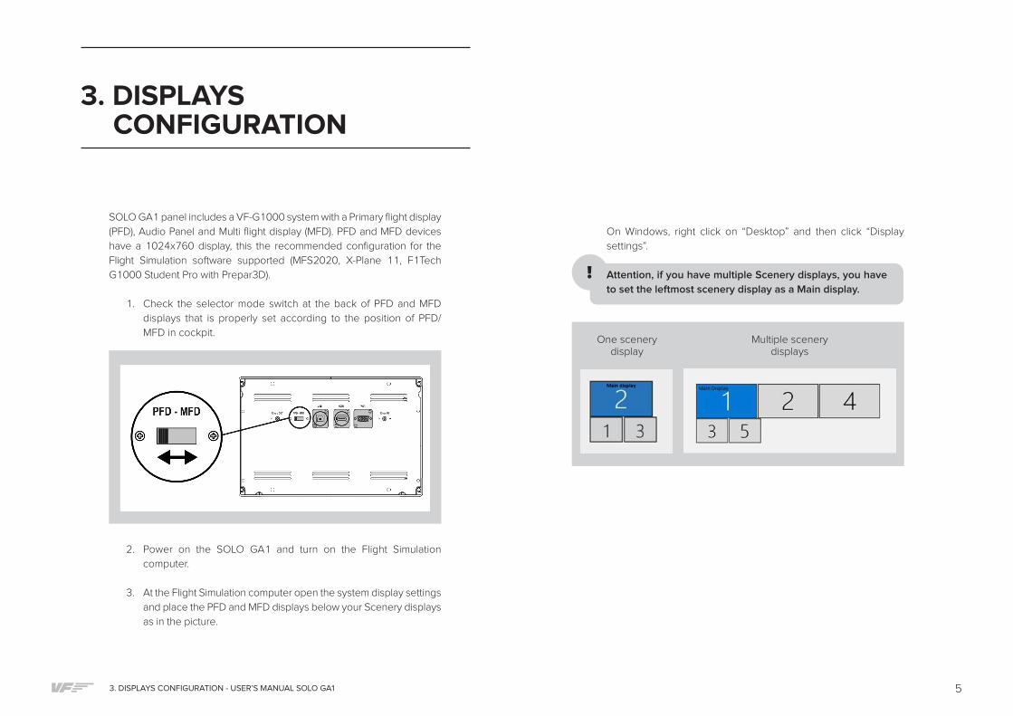
SOLO GA1 panel includes a VF-G1000 system with a Primary flight display
(PFD), Audio Panel and Multi flight display (MFD). PFD and MFD devices
have a 1024x760 display, this the recommended configuration for the
Flight Simulation software supported (MFS2020, X-Plane 11, F1Tech
G1000 Student Pro with Prepar3D).
1. Check the selector mode switch at the back of PFD and MFD
displays that is properly set according to the position of PFD/
MFD in cockpit.
3. DISPLAYS CONFIGURATION
One scenery display
Multiple scenery displays
2. Power on the SOLO GA1 and turn on the Flight Simulation
computer.
3. At the Flight Simulation computer open the system display settings
and place the PFD and MFD displays below your Scenery displays
as in the picture.
On Windows, right click on “Desktop” and then click “Display
settings”.
Attention, if you have multiple Scenery displays, you have
to set the leftmost scenery display as a Main display.
6 4. FLIGHT SIMULATION SOFTWARE CONFIGURATION - USER’S MANUAL SOLO GA1
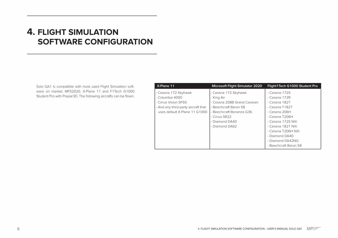
Solo GA1 is compatible with most used Flight Simulation soft-
ware on market: MFS2020, X-Plane 11 and F1Tech G1000
Student Pro with Prepar3D. The following aircrafts can be flown.
4. FLIGHT SIMULATION SOFTWARE CONFIGURATION
X-Plane 11 Microsoft Flight Simulator 2020 Flight1Tech G1000 Student Pro
- Cessna 172 Skyhawk
- Columbia 4000
- Cirrus Vision SF50
- And any third-party aircraft that
uses default X-Plane 11 G1000
- Cessna 172 Skyhawk
- King Air
- Cessna 208B Grand Caravan
- Beechcraft Baron 58
- Beechcraft Bonanza G36
- Cirrus SR22
- Diamond DA40
- Diamond DA62
- Cessna 172S
- Cessna 172R
- Cessna 182T
- Cessna T182T
- Cessna 206H
- Cessna T206H
- Cessna 172S NXi
- Cessna 182T NXi
- Cessna T206H NXi
- Diamond DA40
- Diamond DA42NG
- Beechcraft Baron 58

74. FLIGHT SIMULATION SOFTWARE CONFIGURATION - USER’S MANUAL SOLO GA1
4.1. MFS2020 CONFIGURATION
1. Go to www.virtual-fly.com/Downloads/ Solo-GA1 section. Download
and install the “VF Cockpit SOLO GA 1”, “VF Connect”, “VF G1000
Control Panel MSFS” and “VF Connect Hub” software on MFS2020
computer.
2. Go to www.fsuipc.com and download “FSUIPC for MSFS”.
3. Open “VF Connect”, “VF Connect Hub”, “VF G1000 Control Panel
MSFS” (Select: Single PC, Default assignations), “FSUIPC7” and “VF
Cockpit SOLO GA 1”.
4. Minimize the all the software (Attention: All software has to be run-
ning while using the Solo GA1 panel)
5. Open MFS2020 and load a default G1000 aircraft as Cessna 172.
6. To get the G1000 pop-outs at the PFD and MFD displays, hold down
the Alt Gr (the right Alt key, next to the keyboard) while hovering the
PDF or MFD of the in-game G1000. The cursor will change to a plus
sign, then left click and the window will get out. If you pop-out the PFD
and the MFD, both screens will be combined in the same windows.
4.2. START-UP PROCEDURE FOR MFS2020
1. Power on the Solo GA1 and turn on the Flight Simulation computer.
2. Open “VF Connect”, “VF Connect Hub”, “VF G1000 Control Panel
MSFS”, “FSUIPC7” and “VF Cockpit SOLO GA 1”.
3. Minimize the all the software (Attention: All software has to be run-
ning while using the Solo GA1 panel)
4. Start MFS2020 and load a default G1000 aircraft.
5. Pop-out the G1000 PFD and MFD windows from the aircraft cockpit
to the PFD and MFD displays. (See steps 5 and 6 from MFS2020
Configuration).
6. Place the magnetic labels on SOLO GA1 according to the aircraft
selected in X-Plane 11 if necessary.
7. Solo GA1 is ready to fly.
7. Now, to have them in different windows, click on the + sign. Now
drag the windows to the corresponding screen, make sure that you
do not resize them. Once you have them in the screen you want,
press ALT + ENTER to make them full screen.
8. Solo GA1 is ready to fly!

8 4. FLIGHT SIMULATION SOFTWARE CONFIGURATION - USER’S MANUAL SOLO GA1
4.3. X-PLANE 11 CONFIGURATION
1. Remove the G1000 bezels in X-Plane:
1.1. Download the “G1000PFD_2d.png” and the “G1000MFD_2d.
png” files from www.virtual-fly.com/en/downloads VF-G1000
section and place them in “X-Plane 11\Resources\ bitmaps\coc-
kpit\EFIS\G1000” folder.
2. Go to www.virtual-fly.com/Downloads/ Solo GA1 section. Download
and install the “VF SOLO GA 1”, “VF Connect for X-Plane”, “VF
G1000 Control Panel" and “VF Connect Hub” software on MFS2020
computer.
3. Open “VF Connect”, “VF Connect Hub”, “VF G1000 Control Panel"
(Select: Single PC, Default assignations) and “VF Cockpit SOLO GA 1”.
4. Minimize all the software (Attention: All software has to be running
while using the SOLO GA1 panel)
5. Open X-Plane 11 and load a default G1000 aircraft as Cessna 172.
6. Pup-out the X-Plane G1000 windows to the VF G1000 displays:
6.1. In X-Plane "Settings/Graphics" tab, set PFD and MFD Monitors as
"Unused".
6.2. On 3D cockpit view, click on the PFD virtual G1000 window and
it will pop-out. In the new window, move the mouse to the top-
right corner, a small square icon will appear. Click on it and you
will be able to drag the window to the PFD display. Do the same
process for the MFD virtual G1000 window.
6.3. Resize the PFD virtual G1000 window in order to fit it into the
PFD display. Move the window down to the PFD display but the
top window frame has to remain at the Main display. Repeat the
same process for the MFD G1000 window. When both windows
are properly adjusted, click on the Main display and the top fra-
me of PFD & MFD G1000 windows will be hidden.
Attention, to avoid the Windows snap-in effect, change the
Windows taskbar location to the right side.
7. Solo GA1 is ready to fly!
94. FLIGHT SIMULATION SOFTWARE CONFIGURATION - USER’S MANUAL SOLO GA1
4.4. START-UP PROCEDURE FOR X-PLANE 11
1. Power on the Solo GA1 and turn on the Flight Simulation computer.
2. Open “VF Connect for X-Plane”, “VF Connect Hub”, "VF G1000
Control Panel" (Select: Single PC, Default assignations) and “VF
Cockpit SOLO GA 1”.
3. Minimize all the software (Attention: All software has to be running
while using the SOLO GA1 panel).
4. Start X-Plane 11 and load a default G1000 aircraft.
5. Place the magnetic labels on SOLO GA1 according to the aircraft
selected in X-Plane 11 if necessary.
6. Solo GA1 is ready to fly.
4.5. F1TECH G1000 STUDENT PRO WITH PREPAR3D
CONFIGURATION
1. Power on the SOLO GA1 panel and Flight simulation computer with
Prepar3D and F1Tech G1000 Student Pro software installed.
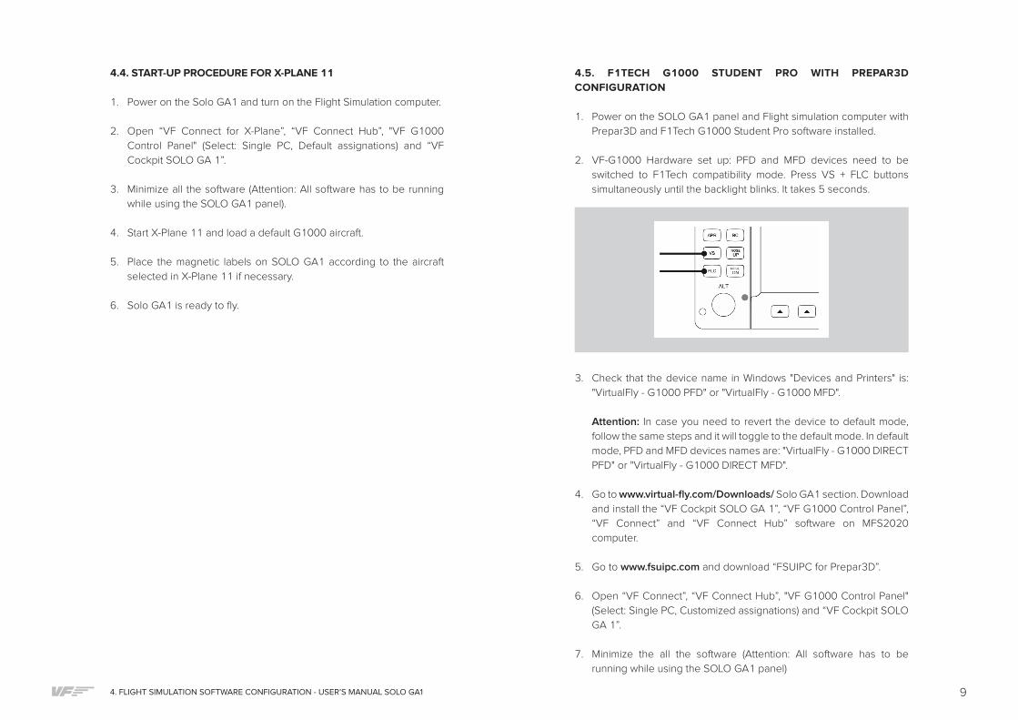
2. VF-G1000 Hardware set up: PFD and MFD devices need to be
switched to F1Tech compatibility mode. Press VS + FLC buttons
simultaneously until the backlight blinks. It takes 5 seconds.
3. Check that the device name in Windows "Devices and Printers" is:
"VirtualFly - G1000 PFD" or "VirtualFly - G1000 MFD".
Attention: In case you need to revert the device to default mode,
follow the same steps and it will toggle to the default mode. In default
mode, PFD and MFD devices names are: "VirtualFly - G1000 DIRECT
PFD" or "VirtualFly - G1000 DIRECT MFD".
4. Go to www.virtual-fly.com/Downloads/ Solo GA1 section. Download
and install the “VF Cockpit SOLO GA 1”, “VF G1000 Control Panel”,
“VF Connect” and “VF Connect Hub” software on MFS2020
computer.
5. Go to www.fsuipc.com and download “FSUIPC for Prepar3D”.
6. Open “VF Connect”, “VF Connect Hub”, "VF G1000 Control Panel"
(Select: Single PC, Customized assignations) and “VF Cockpit SOLO
GA 1”.
7. Minimize the all the software (Attention: All software has to be
running while using the SOLO GA1 panel)
10 4. FLIGHT SIMULATION SOFTWARE CONFIGURATION - USER’S MANUAL SOLO GA1
8. Open F1tech G1000 Student Pro software. In the “Control Panel”
of F1tech select “Hardware” tab, “Platform selection” and choose
“VirtualFly VF 1000” option.
9. Follow the F1Tech G1000 Student Pro instructions for placing the
G1000 PFD and MFD windows on SOLO GA1 displays.
10. Load a F1Tech aircraft in Prepar3D as Cessna 172S.
11. SOLO GA1 is ready to fly.
4.6. START-UP PROCEDURE FOR F1TECH G1000 STUDENT PRO
WITH PREPAR3D
1. Power on the Solo GA1 and turn on the Flight Simulation computer.
2. Open “VF Connect”, “VF Connect Hub”, “VF G1000 Control Panel”
and “VF Cockpit SOLO GA 1”.
3. Minimize the all the software (Attention: All software has to be run-
ning while using the SOLO GA1 panel).
4. Start Prepar3D and load a F1Tech G1000 aircraft.
5. Place the magnetic labels on SOLO GA according to the aircraft se-
lected in X-Plane 11 if necessary.
6. Start F1Tech G1000 Student Pro software.
7. Solo GA1 is ready to fly.
114. FLIGHT SIMULATION SOFTWARE CONFIGURATION - USER’S MANUAL SOLO GA1
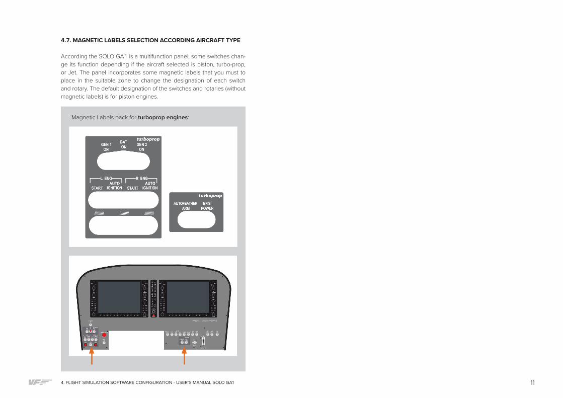
4.7. MAGNETIC LABELS SELECTION ACCORDING AIRCRAFT TYPE
According the SOLO GA1 is a multifunction panel, some switches chan-
ge its function depending if the aircraft selected is piston, turbo-prop,
or Jet. The panel incorporates some magnetic labels that you must to
place in the suitable zone to change the designation of each switch
and rotary. The default designation of the switches and rotaries (without
magnetic labels) is for piston engines.
Magnetic Labels pack for turboprop engines:

12 5. ENGINE STARTING - USER’S MANUAL SOLO GA1
The following procedures are indicated by VirtualFly to start the plane
as simply as possible, never take these procedures for training or for
real aviation.
5.1. STARTING & STOP PISTON ENGINES (USING MFS / P3D)
Starting piston engines (using MFS / P3D)
1. Pull on the PARKING BRAKE.
2. Move the MIXTURE handle to RICH.
3. Move the PROP RPM handle to HIGH.
4. Move the POWER handle to DEC.
5. Switch on the BAT.
6. Switch on the 2 MAGNETO L ENG “L” and “R”.
7. Push on the red “START” left push-button to start the engine.
8. Once the left engine is running, switch on the left L ALT to charge the
battery.
9. Switch on M. AVIONICS.
This procedure has started the single engine if it is a single-engine
airplane or the left engine if it is a twin-engine plane, in the latter case do
the indications 6, 7, 8 to start the right engine.
Stop piston engines (using MFS / P3D)
1. Pull on the PARKING BRAKE.
2. Move the MIXTURE handle to CUTOFF.
3. Switch off the M. AVIONICS.
4. Switch off the alternator/s ALT.
5. Switch off the MAGNETO/S.
6. Switch off the BAT.
5. ENGINE STARTING
3 2
1
Starting piston engines
Stop piston engines
958
67
4
1364
5 2

135. ENGINE STARTING - USER’S MANUAL SOLO GA1
5.2. START & STOP PISTON ENGINES (USING X-PLANE)
Refer to the aircraft manual found in: <X-Plane Installation Folder>/
Aircraft/<The Aircraft Folder>. In the aircraft manual search for the
“Checklists” section. You will find detailed instructions for starting and
stopping the engines.

14 5. ENGINE STARTING - USER’S MANUAL SOLO GA1
5.3. STARTING & STOP TURBOPROP ENGINES (USING MFS / P3D)
Starting turboprop engines (using MFS / P3D)
1. Pull on the PARKING BRAKE
2. Move the MIXTURE handle to RICH
3. Move the PROP RPM handle to HIGH
4. Move the POWER handle to DEC
5. Switch on the BAT
6. Switch on the L ENG “START”
7. Once the left engine is running switch off the L ENG “START”
8. Switch on the GEN 1 to charge the batteries.
9. Switch on M. AVIONICS
This procedure has started the single engine if it is a single-engine
airplane or the left engine if it is a twin-engine plane, in the latter case
do the indications 6, 7, 8, 9 to start the right engine.
IMPORTANT! Before activating GEN do not forget to disable
START, if don’t do that the generator will not charge the batteries.
Stop turboprop engines (using MFS / P3D)
1. Pull on the PARKING BRAKE
2. Move the MIXTURE handle to CUTOFF
3. Switch off the M. AVIONICS
4. Switch off the GEN/S
5. Switch off the BAT
1
1
9
3
5
5
8
4
6 7
3 2
4
Starting turboprop engines
Stop turboprop engines
2

155. ENGINE STARTING - USER’S MANUAL SOLO GA1
5.4. START & STOP TURBOPROP ENGINES (USING X-PLANE)
Refer to the aircraft manual found in: <X-Plane Installation Folder>/
Aircraft/<The Aircraft Folder>. In the aircraft manual search for the
“Checklists” section. You will find detailed instructions for starting and
stopping the engines.

16 6. TROUBLESHOOTING - USER’S MANUAL SOLO GA1
ANOMALY: PFD AND MFD DOES NOT INTERACT WITH FLIGHT
SIMULATION SOFTWARE
POSSIBLE CAUSE 1: PFD and MFD are not set in the right mode for the
flight simulation software used.
SOLUTION:
• If using MFS2020 and X-Plane 11, PFD and MFD devices has to
be listed in Windows “Devices and Printers” as “VirtualFly – PFD
DIRECT” and “VirtualFly – MFD DIRECT”.
• If using F1Tech G1000 Student Pro software, PFD and MFD devices
has to be listed in Windows “Devices and Printers” as “VirtualFly –
PFD” and “VirtualFly – MFD”.
• To change the PFD/MFD mode check chapter 4.5, step 2. VF-
G1000 Hardware set up.
POSSIBLE CAUSE 2: PFD and MFD are not detected in your flight simu-
lator computer.
SOLUTION: Make sure SOLO GA1, PFD and MFD receives 12v power.
Also check in the Flight simulation computer that “Virtual Fly – PFD
DIRECT” and “Virtual Fly – MFD DIRECT” are detected.
POSSIBLE CAUSE 3: “VF G1000 Control Panel” is not running on flight
simulation computer.
SOLUTION: Execute “VF G1000 Control Panel” on the flight simulation
computer. And check if PFD and MFD are detected.
6. TROUBLESHOOTING
ANOMALY: AUDIO PANEL DOES NOT INTERACT WITH FLIGHT
SIMULATION SOFTWARE
POSSIBLE CAUSE: In X-Plane 11, default Joystick assignations are not
set.
SOLUTION: In X-Plane 11 Settings/Joysticks select the “Virtual Fly -
Audio Panel” device and click on “Reset to defaults for Virtual Fly - Audio
Pane” button.
ANOMALY (X-Plane): PRESSING THE START ENGINE BUTTONS
DOESN’T START DE ENGINES
POSSIBLE CAUSE: SOLO GA1 is not fully compatible if the DataRefTool
plugin is installed to x-plane.
SOLUTION: Deactivate or uninstall DataRefTool plugin.

177. REMOTE ASSISTANCE - USER’S MANUAL SOLO GA1
In case you need help from VirtualFly technical service, there is the
possibility to make a remote connection to your Flight Simulator System
using SOLO GA1. For that, you should do the next:
1. Connect your Flight Simulator computer to the Internet.
2. Download and run the following software:
• Windows:
https://get.anydesk.com/qxrLAqmA/AnyDesk_VirtualFly_Client.exe
• Mac OS:
https://get.anydesk.com/OBnE0uMg/AnyDesk_VirtualFly_Client.dmg
3. Take note of the ID code that appear on the screen, as the next
example.
4. Contact with Virtual Fly technical support service
([email protected]) to:
o Give Id code.
o Have a meeting to make a session.
7. REMOTE ASSISTANCE

18 8. TECHNICAL SPECIFICATIONS - USER’S MANUAL SOLO GA1
Power Supply: 110-240 VAC, mono, 50-60 Hz
Nominal intensity: 0,75 A
Weight: 15 kg
Height: 43,5 cm
Depth: 21,5 cm
Width: 80 cm
Compatibility: MFS2020, X-Plane 11, F1Tech G1000 Student Pro with
Prepar3D
8. TECHNICAL SPECIFICATIONS

198. TECHNICAL SPECIFICATIONS - USER’S MANUAL SOLO GA1
M6
M6
172 146204
198
516
218
287138 313
738
97
794
437
210
670
315145
3630
100
11222
2651
180

VIRTUAL FLY
HEADQUARTERS
c. Morales, 39 bajos
08029 Barcelona (Spain)
R & D CENTER - SHOWROOM
c. Maria Aurèlia Capmany, 29
P. I. La Fàbrica
08297 Castellgalí (Spain)
T. (+34) 938 333 301
www.virtual-fly.com