solo identification system - x-rite · avvertimento - non usare questo apparecchio in ambienti...
TRANSCRIPT

VeriColor® Solo Identification System
Setup and Operator Manual

V E R I C O L O R ® S O L O I D E N T I F I C A T I O N S Y S T E M
1
CE Declaration
Hereby, X-Rite, Incorporated, declares that this VCS25, VCS50 is in compliance with the essential requirements and other relevant provisions of Directive(s) EMC 2004/108/EC, LVD 2006/95/EC, and RoHS 2011/65/EU (Category 9, industrial).
Federal Communications Commission Notice
NOTE: This equipment has been tested and found to comply with the limits for a Class A digital device, pursuant to Part 15 of the FCC Rules. These limits are designed to provide reasonable protection against harmful interference when the equipment is operated in a commercial environment. This equipment generates, uses, and can radiate radio frequency energy and, if not installed and used in accordance with the instruction manual, may cause harmful interference to radio communications. Operation of this equipment in a residential area is likely to cause harmful interference in which case the user will be required to correct the interference at his own expense.
Industry Canada Compliance Statement
This Class A digital apparatus complies with Canadian ICES-003.
Cet appareil numérique de la classe A est conforme à la norme NMB-003 du Canada.
Equipment Information
Use of this equipment in a manner other than that specified by X-Rite, Incorporated may compromise design integrity and become unsafe. WARNING: This instrument is not for use in explosive environments. ADVERTENCIA - NO use este aparato en los ambientes explosivos. AVVERTIMENTO - NON usare questo apparecchio in ambienti esplosivi. WARNUNG: Das Gerät darf in einer explosiven Umgebung NICHT verwendet werden. AVERTISSEMENT: Cet instrument ne doit pas être utilisé dans un environnement explosif.
Instructions for disposal: Please dispose of Waste Electrical and Electronic Equipment (WEEE) at designated collection points for the recycling of such equipment.
Proprietary Notice
The information contained in this manual is derived from patent and proprietary data of X-Rite, Incorporated. The contents of this manual are the property of X-Rite, Incorporated and are copyrighted. Any reproduction in whole or part is strictly prohibited. Publication of this information does not imply any rights to reproduce or use this manual for any purpose other than installing, operating, or maintaining this instrument. No part of this manual may be reproduced, transcribed, transmitted, stored in a retrieval system, or translated into any language or computer language, in any form or by any means, electronic, magnetic, mechanical, optical, manual, or otherwise, without the prior written permission of an officer of X-Rite, Incorporated.
This product may be covered by one or more patents. Refer to the instrument for actual patent numbers.
Copyright © 2013 by X-Rite, Incorporated “ALL RIGHTS RESERVED” X-Rite and VeriColor are registered trademarks of X-Rite, Incorporated. All other logos, brand names, and product names mentioned are the properties of their respective holders.

V E R I C O L O R ® S O L O I D E N T I F I C A T I O N S Y S T E M
2
Warranty Information
X-Rite warrants this Product against defects in material and workmanship for a period of twelve (12) months from the date of shipment from X-Rite’s facility, unless mandatory law provides for longer periods. During such time, X-Rite will either replace or repair at its discretion defective parts free of charge.
X-Rite’s warranties herein do not cover failure of warranted goods resulting from: (i) damage after shipment, accident, abuse, misuse, neglect, alteration or any other use not in accordance with X-Rite’s recommendations, accompanying documentation, published specifications, and standard industry practice; (ii) using the device in an operating environment outside the recommended specifications or failure to follow the maintenance procedures in X-Rite’s accompanying documentation or published specifications; (iii) repair or service by anyone other than X-Rite or its authorized representatives; (iv) the failure of the warranted goods caused by use of any parts or consumables not manufactured, distributed, or approved by X-Rite; (v) any attachments or modifications to the warranted goods that are not manufactured, distributed or approved by X-Rite. Consumable parts and Product cleaning are also not covered by the warranty.
X-Rite‘s sole and exclusive obligation for breach of the above warranties shall be the repair or replacement of any part, without charge, which within the warranty period is proven to X-Rite‘s reasonable satisfaction to have been defective. Repairs or replacement by X-Rite shall not revive an otherwise expired warranty, nor shall the same extend the duration of a warranty.
Customer shall be responsible for packaging and shipping the defective product to the service center designated by X-Rite. X-Rite shall pay for the return of the product to Customer if the shipment is to a location within the region in which the X-Rite service center is located. Customer shall be responsible for paying all shipping charges, duties, taxes, and any other charges for products returned to any other locations. Proof of purchase in the form of a bill of sale or receipted invoice which is evidence that the unit is within the Warranty period must be presented to obtain warranty service. Do not try to dismantle the Product. Unauthorized dismantling of the equipment will void all warranty claims. Contact the X-Rite Support or the nearest X-Rite Service Center, if you believe that the unit does not work anymore or does not work correctly.
THESE WARRANTIES ARE GIVEN SOLELY TO BUYER AND ARE IN LIEU OF ALL OTHER WARRANTIES, EXPRESSED OR IMPLIED, INCLUDING BUT NOT LIMITED TO THE IMPLIED WARRANTIES OF MERCHANTABILITY, FITNESS FOR A PARTICULAR PURPOSE OR APPLICATION, AND NON-INFRINGEMENT. NO EMPLOYEE OR AGENT OF X-RITE, OTHER THAN AN OFFICER OF X-RITE, IS AUTHORIZED TO MAKE ANY WARRANTY IN ADDITION TO THE FOREGOING.
IN NO EVENT WILL X-RITE BE LIABLE FOR ANY OF BUYER’S MANUFACTURING COSTS, OVERHEAD, LOST PROFITS, GOODWILL, OTHER EXPENSES OR ANY INDIRECT, SPECIAL, INCIDENTAL OR CONSEQUENTIAL DAMAGES BASED UPON BREACH OF ANY WARRANTY, BREACH OF CONTRACT, NEGLIGENCE, STRICT TORT, OR ANY OTHER LEGAL THEORY. IN ANY EVENT OF LIABILITY, X-RITE’S MAXIMUM LIABILITY HEREUNDER WILL NOT EXCEED THE PRICE OF THE GOODS OR SERVICES FURNISHED BY X-RITE GIVING RISE TO THE CLAIM.
V E R I C O L O R ® S O L O I D E N T I F I C A T I O N S Y S T E M
3
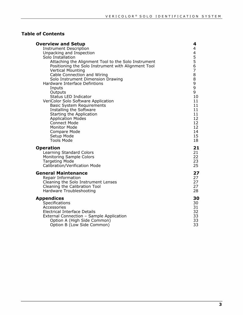
Table of Contents
Overview and Setup 4 Instrument Description 4 Unpacking and Inspection 4 Solo Installation 5
Attaching the Alignment Tool to the Solo Instrument 5 Positioning the Solo Instrument with Alignment Tool 6 Vertical Mounting 7 Cable Connection and Wiring 8 Solo Instrument Dimension Drawing 8
Hardware Interface Defintions 9 Inputs 9 Outputs 9 Status LED Indicator 10
VeriColor Solo Software Application 11 Basic System Requirements 11 Installing the Software 11 Starting the Application 11 Application Modes 12 Connect Mode 12 Monitor Mode 12 Compare Mode 14 Setup Mode 15 Tools Mode 18
Operation 21 Learning Standard Colors 21 Monitoring Sample Colors 22 Targeting Mode 23 Calibration/Verification Mode 25
General Maintenance 27 Repair Information 27 Cleaning the Solo Instrument Lenses 27 Cleaning the Calibration Tool 27 Hardware Troubleshooting 28
Appendices 30 Specifications 30 Accessories 31 Electrical Interface Details 32 External Connection – Sample Application 33
Option A (High Side Common) 33 Option B (Low Side Common) 33

V E R I C O L O R ® S O L O I D E N T I F I C A T I O N S Y S T E M
4
Overview and Setup Instrument Description
The VeriColor® Solo Identification System is used to evaluate and identify colors in an industrial type application. It provides the means necessary to learn (measure) standard colors and measure samples for comparison. The system uses these comparisons to determine the closest standard or pass/fail a sample based on a tolerance.
The Solo system is composed of two main components: the VeriColor Solo sensor head which stores standard colors and captures sample color, and the software application.
Unpacking and Inspection After removing the instrument from the shipping carton, inspect it for damage. If any damage has occurred during shipping, immediately contact the transportation company. Do not proceed with installation until the carrier’s agent has inspected the damage.
Your instrument was packaged in a specially designed carton to assure against damage. If shipment is necessary, the instrument should be packaged in the original carton along with all the accessories. If the original carton is not available, contact X-Rite to have a replacement shipped to you.
Packaging Contents: • VeriColor Solo Instrument P/N VCS50-00-01
• 5 Meter Male 8-Circuit Open Ended Cable P/N SE108-EUR8-5M
• 5 Meter Female 8-Circuit Open Ended/DB9 Cable P/N VCS50-EUR8-5DB
• Alignment Tool P/N VC50-803
• Calibration Tool P/N VC100-162
• Targeting Stickers (4) Medium Spot P/N VC50-32
• VeriColor Solo Application Software CD P/N VCS50-500-CD
• Setup and Operation Manual P/N VCS50-500
• Registration Fax (multi-language) P/N SD01-99
Sensor Port
RS-232 Connector
Illumination Port
Status LED Indicator
PLC Connector

V E R I C O L O R ® S O L O I D E N T I F I C A T I O N S Y S T E M
5
Solo Installation An alignment tool is provided with the Solo instrument to aid in the installation. The tool simply snaps into position, providing the required angle (30°) and height (1.40”) needed for proper mounting.
CAUTION: Keep the sensor port lens and illumination port lens free from dust, smudge marks, and finger prints.
Attaching the Alignment Tool to the Solo Instrument 1. Position the end of the alignment tool shown over the tab on the sensor port side of
the Solo instrument. The tab should insert into a slotted opening in the tool.
2. Rotate the other end of the tool upward until it snaps into place over the tab on the illumination port of the Solo instrument.
NOTE: The alignment tool will only install in one direction.
Tab Tab
Illumination port
Sensor port
Alignment guide
Correct Alignment Incorrect Alignment

V E R I C O L O R ® S O L O I D E N T I F I C A T I O N S Y S T E M
6
Positioning the Solo Instrument with Alignment Tool 1. Locate the Solo instrument in the fixture with the flat surface of the alignment tool
on the part to measure. Using the groove that runs along the bottom of the flat surface as a guide, position the solo instrument to the desired measurement spot. The groove is the location where the measurement will take place.
2. When the Solo instrument is properly located, secure it to the fixture using the four mounting holes. Remove the part from the fixture.
3. Remove the alignment tool by pulling outward (1) on the sensor port side of the tool and rotating downward (2).
Mounting hole (4)
Measurement spot (tool groove)
Sample part
(1)
(2)

V E R I C O L O R ® S O L O I D E N T I F I C A T I O N S Y S T E M
7
Vertical Mounting As an alternative to tilted mounting, you can mount the Solo instrument in a vertical position. However, X-Rite recommends mounting the sensor head at a 30° angle untilizing the alignment tool.
1.40" (±.125)
Sensor Port
Illumination Port
Mounting Hole (4)
Fixture Solo Instrument
Sample Part

V E R I C O L O R ® S O L O I D E N T I F I C A T I O N S Y S T E M
8
Cable Connection and Wiring 1. Connect the female connector (P/N VCS50-EUR8-5DB) from the RS-232 interface
cable to the Solo instrument and tighten.
2. Connect the male connector (P/N SE108-EUR8-5M) from the PLC interface cable to the Solo instrument and tighten.
3. Attach the individual wires to the terminals on the PLC and RS-232 connector (DB-9) as required. Refer to the wiring diagram below for details.
See the Appendices (page 32) for a detailed electrical interface description.
Solo Instrument Dimension Drawing
RS-232 Cable (P/N VCS50-EUR8-5DB)
#2 – Negative (brown)
#1 - +24 Vdc (white)
#5 – DSR (gray)
#6 – 10’s (pink)
#7 – 1’s (blue)
#8 – READ (red)
Cable Shield (Panel or fixture ground)
PLC Cable (P/N SE108-EUR8-5M)
#1 – PASS (white)
#2 – FAIL (brown)
#3 – Comm (green)
#4 – Ch-E 16 (yellow)
#5 – Ch-D 8 (gray)
#6 – Ch-C 4 (pink)
#7 – Ch-B 2 (blue)
#8 – Ch-A 1 (red)
Cable Shield (Panel or Fixture ground)
DB9 Connector Pin 5 – #2 Ground (brown)
Pin 2 – #3 Txout (green)
Pin 3 – #4 Rvin (yellow)
V E R I C O L O R ® S O L O I D E N T I F I C A T I O N S Y S T E M
9
Hardware Interface Defintions The Solo instrument communicates externally via PLC, serial communications, and an LED indicator. The following lists the available inputs and outputs.
Inputs
Measurement Trigger This input is used to prompt the Solo instrument to begin the measurement sequence immediately (or a specified pause). The type of measurement depends on the operation mode (during some instances this input will be ignored). Measurements can also be triggered by serial command.
Color Select This input allows you to select the color ahead of time, before a measurement is taken. The process to use color select, is to activate it first, then toggle the 1’s and/or 10’s select inputs to arrive at the desired color number. Each time the color select input is activated, new measurements are locked out and the color number starts at 0. If the color select input is released without changing the number, it will go back to the color number selected before the process was started.
1’s Select This input can only be used while the color select input is being held active. During that time, each time this input is activated and released the color number will increment by 1. Example, if the color number is currently 4, after two toggles the color number will be 6. If the number is 19 then it would become 21 after two toggles. Since the Solo instrument stores a maximum of 30 colors, no number higher than 30 can be selected, even if additional increments to the input are made.
10’s Select This operates much the same as the 1’s input except it provides a way to select higher numbers quicker than the 1’s input alone. For example, if you want to select color number 29, you would toggle the 10’s input twice and the 1’s input 9 times.
Outputs
Pass This output indicates that the last sample measurement(s) was determined to be within the active tolerance for the selected color. This output defaults to NO (normally open) operation, but can be switched to NC (normally closed) operation with a configuration setting. This setting affects all output operation as follows.
Fail This output indicates that the last sample measurement(s) had a greater color difference than the active tolerance for the selected Color allowed. Like Pass, this output defaults to NO (normally open) operation but can be switched to NC.
Programmable Output Ports (5 bits) This output is solely used to portray the color number in binary format. Like Pass and Fail outputs, the operation of these outputs default to NO operation and can be configured to NC.

V E R I C O L O R ® S O L O I D E N T I F I C A T I O N S Y S T E M
10
Status LED Indicator On the back plate of the Solo instrument is an LED indicator capable of displaying three colors, Green, Amber and Red. In some cases the LED will flash, but most of the time it will remain on. This LED is simply an indicator to give you “at a glance” the overall status of the instrument. A description of each color status is listed below.
Off – This generally means the Solo instrument has no or insufficient power.
Flashing Amber – When the instrument is first powered up, it will slowly flash while undergoing system test, and waiting for the illumination LED pack to warm up to temperature.
Solid Green – indicates the instrument is ready and waiting for further input (discrete input or serial port).
Solid Amber – indicates the instrument is busy and performing a requested task. Whenever a PLC input or serial command is being processed, the status light should remain amber until it is ready for the next request.
Solid Red – indicates system error/failure. If this occurs then the instrument is not functioning and cannot be used until the problem is resolved.
V E R I C O L O R ® S O L O I D E N T I F I C A T I O N S Y S T E M
11
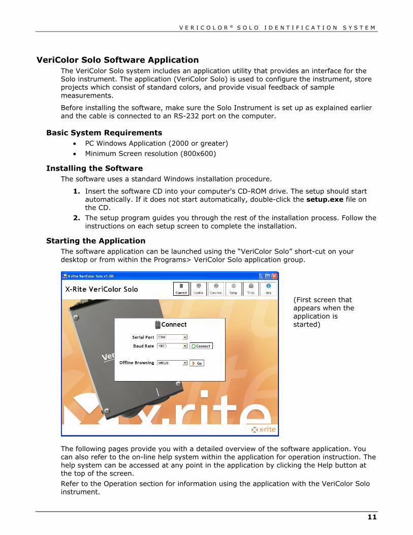
VeriColor Solo Software Application The VeriColor Solo system includes an application utility that provides an interface for the Solo instrument. The application (VeriColor Solo) is used to configure the instrument, store projects which consist of standard colors, and provide visual feedback of sample measurements.
Before installing the software, make sure the Solo Instrument is set up as explained earlier and the cable is connected to an RS-232 port on the computer.
Basic System Requirements • PC Windows Application (2000 or greater)
• Minimum Screen resolution (800x600)
Installing the Software The software uses a standard Windows installation procedure.
1. Insert the software CD into your computer's CD-ROM drive. The setup should start automatically. If it does not start automatically, double-click the setup.exe file on the CD.
2. The setup program guides you through the rest of the installation process. Follow the instructions on each setup screen to complete the installation.
Starting the Application The software application can be launched using the “VeriColor Solo” short-cut on your desktop or from within the Programs> VeriColor Solo application group.
The following pages provide you with a detailed overview of the software application. You can also refer to the on-line help system within the application for operation instruction. The help system can be accessed at any point in the application by clicking the Help button at the top of the screen.
Refer to the Operation section for information using the application with the VeriColor Solo instrument.
(First screen that appears when the application is started)

V E R I C O L O R ® S O L O I D E N T I F I C A T I O N S Y S T E M
12
Application Modes The VeriColor Solo application is divided into six main modes, which are navigated by using the six buttons located at the top of the screen.
• Connect – used to establish connection to the VeriColor Solo instrument
• Monitor – used to monitor the sample measurements after the system is set up
• Compare – used to compare sample measurements without storing sample data
• Setup – used to create projects and color standards
• Tools – used to access the device Name, targeting, calibration, log file, etc.
• Help – used to access online help for the displayed dialog
Connect Mode The Connect screen is used to select the communication port were the VeriColor Solo instrument is connected, and to perform off-line browsing.
Communication is established by selecting the known COM port using the Serial Port control and baud rate using the Baud Rate control. After selecting OK, the Monitor screen opens.
The Off-line Browsing control is used to select a device and project for viewing.
Monitor Mode The Monitor screen is the “main” mode of the application. The Monitor mode is used to view measurement performance once the standard colors are setup. Sample results from measurements activated remotely also appear on this screen.
V E R I C O L O R ® S O L O I D E N T I F I C A T I O N S Y S T E M
13
Measure
The Measure button is used to activate a measurement by the Solo instrument.
Standard Selection
The current standard used by the Solo instrument is displayed at the top-left portion of the screen. The same control can be used to select a different standard if more than one exists in the current project.
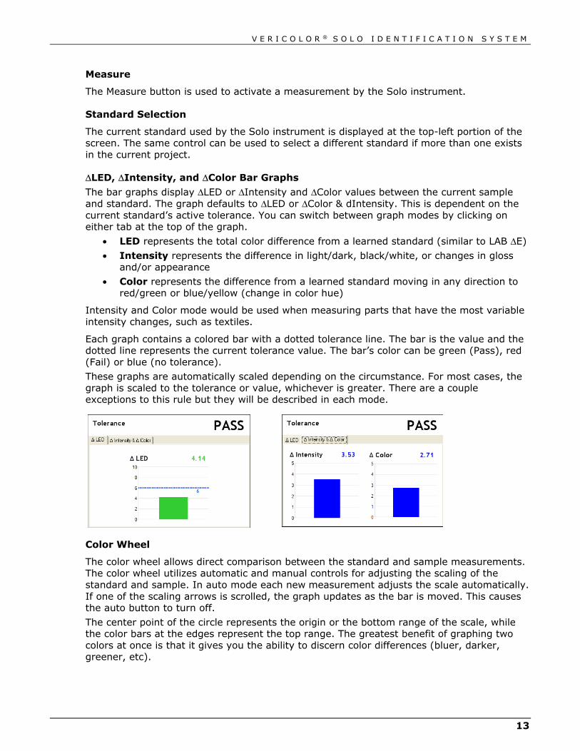
ΔLED, ΔIntensity, and ΔColor Bar Graphs
The bar graphs display ΔLED or ΔIntensity and ΔColor values between the current sample and standard. The graph defaults to ΔLED or ΔColor & dIntensity. This is dependent on the current standard’s active tolerance. You can switch between graph modes by clicking on either tab at the top of the graph.
• LED represents the total color difference from a learned standard (similar to LAB ΔE)
• Intensity represents the difference in light/dark, black/white, or changes in gloss and/or appearance
• Color represents the difference from a learned standard moving in any direction to red/green or blue/yellow (change in color hue)
Intensity and Color mode would be used when measuring parts that have the most variable intensity changes, such as textiles.
Each graph contains a colored bar with a dotted tolerance line. The bar is the value and the dotted line represents the current tolerance value. The bar’s color can be green (Pass), red (Fail) or blue (no tolerance).
These graphs are automatically scaled depending on the circumstance. For most cases, the graph is scaled to the tolerance or value, whichever is greater. There are a couple exceptions to this rule but they will be described in each mode.
Color Wheel
The color wheel allows direct comparison between the standard and sample measurements. The color wheel utilizes automatic and manual controls for adjusting the scaling of the standard and sample. In auto mode each new measurement adjusts the scale automatically. If one of the scaling arrows is scrolled, the graph updates as the bar is moved. This causes the auto button to turn off.
The center point of the circle represents the origin or the bottom range of the scale, while the color bars at the edges represent the top range. The greatest benefit of graphing two colors at once is that it gives you the ability to discern color differences (bluer, darker, greener, etc).

V E R I C O L O R ® S O L O I D E N T I F I C A T I O N S Y S T E M
14
Status The status of the Solo instrument is displayed in a box at the bottom of screen. The back ground color reflects the state of the instrument.
• Green = ready
• Yellow = warming up
• Red = system error
Log
Current log information is displayed in a box at the bottom of the screen. Check the Log box to turn logging on.
Compare Mode The Compare mode is useful for quickly determining the color difference between two separate measurements. Measurements taken on this screen do not affect the current setup, log file, or require the Solo instrument to be setup with a project.
Measure A and Measure B
A measurement taken using the Measure A button is displayed as Sample A data, and a measurement taken using the Measure B button is displayed as Sample B data. The results displayed is the difference between Sample A and Sample B. The last measurement taken using either button remains current until the application is restarted.
Bar Graphs and Color Wheel The bar graphs display the same as in the Monitor mode without tolerancing. The color wheel controls are the same as on the Monitor screen.

V E R I C O L O R ® S O L O I D E N T I F I C A T I O N S Y S T E M
15
Status
The status box displays works the same as on the Monitor screen.
Setup Mode The Setup mode is used to create, edit and delete projects. A single project can consist of up to 30 standard colors and configuration settings. Once created, a project is downloaded and stored in the Solo instrument. Once the Solo Instrument is programmed with a project, it can execute independent of the software application.
Project Selection The current project name is displayed at the top portion of the screen. The same control can be used to select a different project if more than one exists.
New Project
The New Project button is used to create a new project. Once clicked, you are prompted to enter a new project name.
Delete Project The Delete Project button is used to delete the currently selected project. Deleted projects cannot be restored.
Assign Color Fields The Assign fields display the standard color names for the project. Each project may contain up to 30 standards.
New Color
The New Color button opens the Project Setup screen where the standard is learned (see New Color Learn). This procedure is repeated for each new standard created.
Edit Color The Edit Color button is used to open the learn screen for the selected standard. From here, measurement can be taken for the existing standard.
Delete Color The Delete Color button is used to delete the selected standard color. Deleted colors cannot be restored.
Auto Select Color
The Auto Select Color option allows the Solo instrument to select the closest standard color from the list of standards during sample measurements. Selecting On activates this option and selecting Off requires you to manually select the standard before a sample measurement.

V E R I C O L O R ® S O L O I D E N T I F I C A T I O N S Y S T E M
16
NOTE: The software uses the LED method when searching for the closest color from the saved standards.
Pass/Fail Indicator
The Pass/Fail Indicator option is used to assign a pass or fail status to each sample measurement, based on the tolerancing. Selecting On activates this option and selecting Off disables this option.
Update
The Update button downloads the selected project to the Solo instrument.
Advanced Options
The Advanced button opens the Advanced Options screen where additional options for the selected project can be set. After the options are set, the Done button is clicked to return you back to the main project screen.
Output Timeout Determines how long the instrument holds its outputs active after a measurement occurs. The control can be adjusted from 0 to 99 seconds.
Averaging (Sampling)
Determines the amount of measurement taken to obtain an average, and how much time elapses between measurements. The averaging control can be turned off, or adjusted from 2 to 10 measurements to average. Time delayed between measurements can be set from Manual to 9.9 seconds. When the control is set to Manual, the Measure button much be clicked to take the measurement. When set to a time increment, the Solo instrument will pause between measurements.
Measure Trigger Delay (PLC input)
Determines the amount of time the Solo instrument will “pause” after seeing the measurement input go activate (discrete input only). This occurs before an actual measurement is taken. The control can be adjusted from 0 to 2.0 seconds.
Output Operation
Determines the normal operation state of the instrument outputs. Setting can be toggled between normally closed and normally open.
Digital Filtering
The Digital Filtering option is an alternative to simply averaging a set of readings. This method applies a weighting factor across multiple readings. It ranges from 3 to 20 and, when active in the application, is indicated within the sensor status panel.
V E R I C O L O R ® S O L O I D E N T I F I C A T I O N S Y S T E M
17
Search Method
Determines which math formula is used by the software and the Solo instrument to find the next closest color. The instrument uses it for determining the closest color after a measurement, and the software uses this setting during the Learn mode (to help with Auto Max tolerancing).
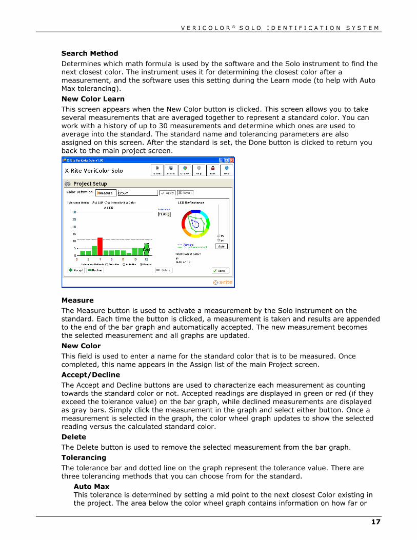
New Color Learn This screen appears when the New Color button is clicked. This screen allows you to take several measurements that are averaged together to represent a standard color. You can work with a history of up to 30 measurements and determine which ones are used to average into the standard. The standard name and tolerancing parameters are also assigned on this screen. After the standard is set, the Done button is clicked to return you back to the main project screen.
Measure The Measure button is used to activate a measurement by the Solo instrument on the standard. Each time the button is clicked, a measurement is taken and results are appended to the end of the bar graph and automatically accepted. The new measurement becomes the selected measurement and all graphs are updated.
New Color This field is used to enter a name for the standard color that is to be measured. Once completed, this name appears in the Assign list of the main Project screen.
Accept/Decline
The Accept and Decline buttons are used to characterize each measurement as counting towards the standard color or not. Accepted readings are displayed in green or red (if they exceed the tolerance value) on the bar graph, while declined measurements are displayed as gray bars. Simply click the measurement in the graph and select either button. Once a measurement is selected in the graph, the color wheel graph updates to show the selected reading versus the calculated standard color.
Delete
The Delete button is used to remove the selected measurement from the bar graph.
Tolerancing
The tolerance bar and dotted line on the graph represent the tolerance value. There are three tolerancing methods that you can choose from for the standard.
Auto Max This tolerance is determined by setting a mid point to the next closest Color existing in the project. The area below the color wheel graph contains information on how far or

V E R I C O L O R ® S O L O I D E N T I F I C A T I O N S Y S T E M
18
close the next closest color is. This is the default method, and allows the most buffer space between colors in a project and is suggested for beginning users simply trying to identify colors.
Auto Min This tolerance is determined by a certain margin over the worst deviating measurement vs. the standard. This would be used if you have a certain acceptable production color variation but want to catch parts that were off color.
Manual This setting allows you to manually set the tolerance by clicking in the field and entering a value.
Tools Mode The Tools mode is used to access instrument information, communication setup, targeting procedure, calibration procedure, and the log file.
Device Screen The device screen provides the system status and the ability to edit the instrument’s name. Enter a name in the name field and click Apply. It also provides you with a method to revert instrument’s name back after it’s changed.
Communication Screen This communication screen is used to change the current BAUD rate. Select the rate from the RS-232 BAUD Rate control and click Apply.
V E R I C O L O R ® S O L O I D E N T I F I C A T I O N S Y S T E M
19
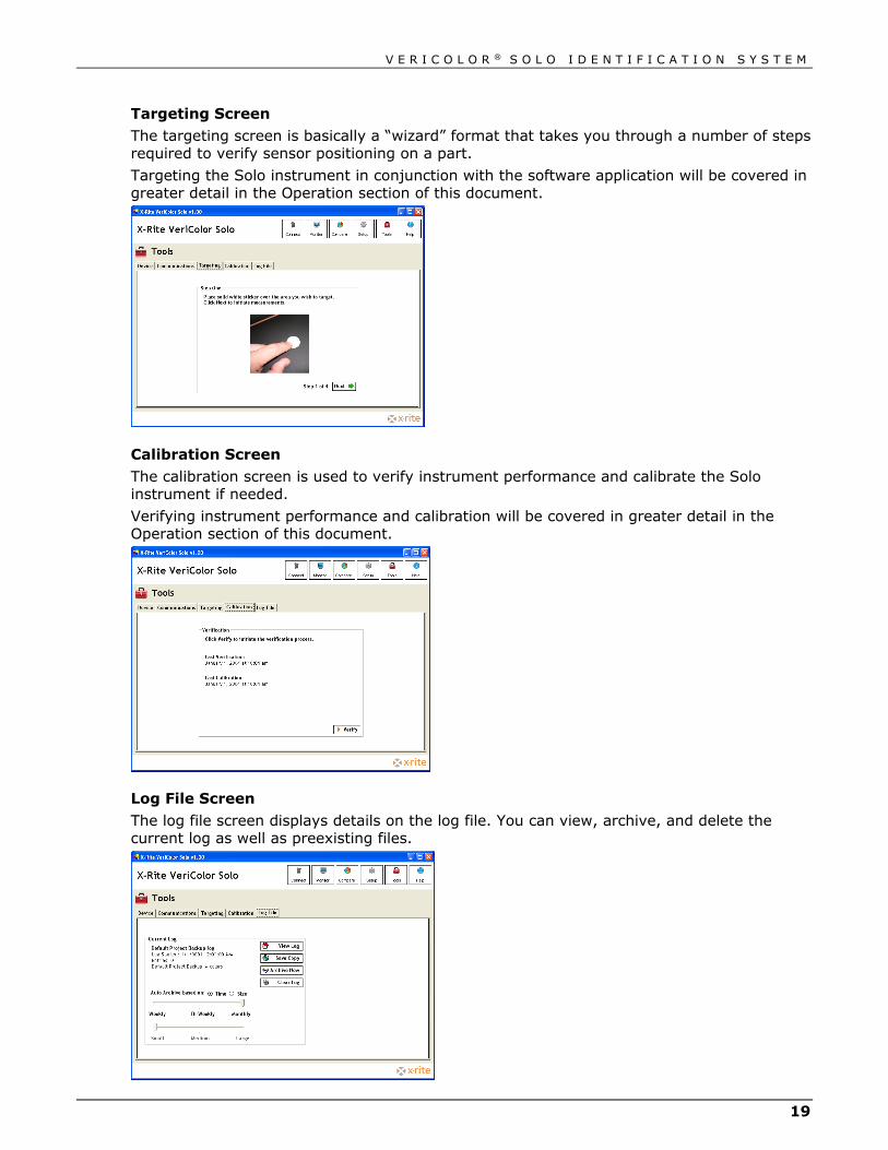
Targeting Screen
The targeting screen is basically a “wizard” format that takes you through a number of steps required to verify sensor positioning on a part.
Targeting the Solo instrument in conjunction with the software application will be covered in greater detail in the Operation section of this document.
Calibration Screen
The calibration screen is used to verify instrument performance and calibrate the Solo instrument if needed.
Verifying instrument performance and calibration will be covered in greater detail in the Operation section of this document.
Log File Screen
The log file screen displays details on the log file. You can view, archive, and delete the current log as well as preexisting files.

V E R I C O L O R ® S O L O I D E N T I F I C A T I O N S Y S T E M
20
Current Log Information
The Current Log area of the screen defaults to the log file in use by the current project in the Solo instrument.
View Log The View Log button launches an Excel viewer of the current log file.
Clear Log The Clear Log button empties the current log information. Deleted log files cannot be restored.
Auto Archive Control
The Auto Archive control allows you to determine how frequently log files are automatically archived to the hard drive and a new one started. Log file names are based on the project name and current date. The directory name is based on the Solo instrument serial number. You can archive based on time (weekly, bi-weekly or monthly) or size (small, medium or large).
Archive Now The Archive Now button allows you to manually archive the current log file at anytime. You can rename the file if desired and determine where it should be saved.
Save Copy
The Save Copy button allows you to save a copy of the current log file.
V E R I C O L O R ® S O L O I D E N T I F I C A T I O N S Y S T E M
21
Operation This section will guide you through the requirements for learning standards, monitoring samples, targeting, and verifying calibration. As mentioned earlier, you can also access specific information on the application utilizing the online help system.
Learning Standard Colors Leaning is the method of measuring a part that is used as standard color for sample comparison. Up to 30 standard colors can be learned and saved in a project for downloading to the Solo instrument.
NOTE: When operating in environments above 40°C, the instrument should be calibrated and standards should be learned at the operating temperature to maintain best performance and color resolution.
Important Learn Mode Notes As long as the fixture is repeatable (parts placed in the fixture are held in the same position consistently) one measurement per part should be adequate. Repeated measurements of the same part without moving/replacing is unnecessary.
Ideally, the part should be taken in and out of the fixture several times and measured to take into account any positional variations. This does not mean that the part should move freely under the head while measuring various spots. The area measured should be held consistently.
Identical parts from different lots should also be measured in case their colors vary slightly between production runs.
1. Start the application and select the Setup screen.
2. Setup new project and configure options. See previous section for information on performing these tasks.
3. Click New Color and enter standard color name.
4. Position the part in the fixture that is to be used for a standard.
5. Click the Measure button to take the measurement.
6. Reposition the part (or position a different part) and take additional measurements.
7. Select the desired tolerancing method and accept or decline measurement as needed.
8. When you have finished measuring the standard to achieve an average, click Done to return to the main project setup screen.
9. Continue with the next standard by placing the part in the fixture and entering a name.

V E R I C O L O R ® S O L O I D E N T I F I C A T I O N S Y S T E M
22
Monitoring Sample Colors Use the Monitor screen to measure sample parts and monitor the Pass/fail status.
1. Start the application and select the Monitor screen.
2. Verify the correct project is selected. If not, select the desired project from the Setup screen and click the Update button to upload the project to the instrument.
3. If auto color is not used, select the standard color that will be used for sample comparison.
4. Position the sample in the fixture.
5. Click the Measure button to measure the sample. The software will automatically select the closest standard from the project (if auto color is activated), and display the result in bar graph and color wheel.
6. Remove the sample and continue with additional sample parts.

V E R I C O L O R ® S O L O I D E N T I F I C A T I O N S Y S T E M
23
Targeting Mode Because the Solo instrument over illuminates, it is sometime difficult to tell exactly where the instrument is viewing to determine color. This is particular true for small part measurements.
Targeting a part is the method of adjusting the sensor head on the fixture to the required position for part measurements. Performing the targeting procedure is only needed if the location of the part to be measured is critical. For example, the measurement area is small or very close to the spot size of the sensor head.
Important Targeting Mode Notes:
Before leaving target mode, test the fixture’s alignment and repeatability by removing and installing the sample several times as done in a production environment. If the ΔLED’s value differs significantly when the part is placed in and out, then the fixture needs to become more precise. Otherwise, the results will be unsatisfactory.
Each time targeting mode is started, the instrument will need to relearn the (white sticker only) target.
1. Start the application; select the Tools screen and then the Targeting screen.
2. Place the white sticker over the target area of the part you intend on measuring.
3. Place the part in the fixture to begin targeting.
4. Click Next on Step One screen to start the continuous measurement sequence.
5. Without disturbing the pre-aligned height and angle position of the Solo instrument, carefully adjust the sensor head (x and y coordinates) so the flashing spot is centered in the middle of the white sticker.
White Targeting Sticker
Illuminating Spot
Sample Part

V E R I C O L O R ® S O L O I D E N T I F I C A T I O N S Y S T E M
24
6. After the desired positioning is achieved, click Next on Step Two screen. This takes the last measurement and saves it as the target value for the Solo instrument.
7. Remove the part from the fixture and remove the white sticker. Place the black ring
sticker in the same location. The black ring is used to help “fine tune” the alignment.
8. Place the part back in the fixture and click Next on the Step Three screen.
9. View the bar graph on the Step Four screen. If the ΔLED value has increased, you
will need to fine tune the Solo instrument. This is due to the fact that the flashing spot from the Solo instrument may be measuring part of the black outer ring. If this occurs, fine tune the sensor head to get the smallest ΔLED value possible. Be careful not to change the sensor head’s height and angle adjustment. A ΔLED value of 1.0 or under should be achievable.
10. After the Solo instrument is targeted, click Stop to exit targeting mode.
Black Targeting Ring Sticker
Illuminating Spot Sample Part
V E R I C O L O R ® S O L O I D E N T I F I C A T I O N S Y S T E M
25
Calibration/Verification Mode The Solo instrument comes with a calibration tool that is used to verify measurement performance and for calibrating the device if needed. Calibration should be verified anytime measurement performance is in question. Poor measurement performance can be caused by dust or dirt on the sensor port. Refer to the Cleaning section later in this document for procedure on cleaning the Solo instrument.
NOTE: When operating in environments above 40°C, the instrument should be calibrated and standards should be learned at the operating temperature to maintain best performance and color resolution.
IMPORTANT: Do not touch the white SRM disk inside the calibration tool. It must be kept clean to ensure accurate measurements. Always store the calibration tool in its bag when not in use.
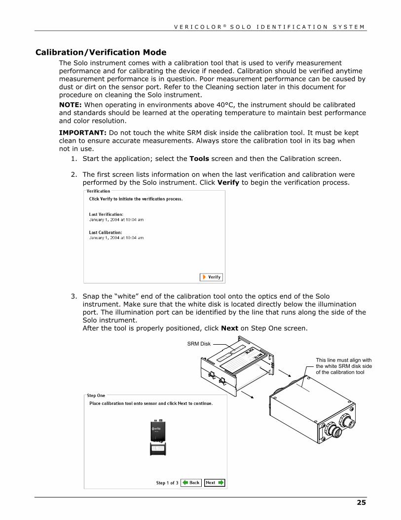
1. Start the application; select the Tools screen and then the Calibration screen.
2. The first screen lists information on when the last verification and calibration were performed by the Solo instrument. Click Verify to begin the verification process.
3. Snap the “white” end of the calibration tool onto the optics end of the Solo instrument. Make sure that the white disk is located directly below the illumination port. The illumination port can be identified by the line that runs along the side of the Solo instrument. After the tool is properly positioned, click Next on Step One screen.
This line must align with the white SRM disk side of the calibration tool
SRM Disk

V E R I C O L O R ® S O L O I D E N T I F I C A T I O N S Y S T E M
26
4. Click Measure on the Step Two screen. The ΔLED bar graph appears and a PASS or FAIL status is indicated. The tolerancing can be changed by clicking on tolerance arrow and entering a value. You can also click the tolerance arrow and drag it up and down to the desired level. Each time the Measure button is clicked, a new verification test is performed.
5. If the verification passed, remove the calibration tool and exit out of the verification
procedure. If a failure occurred, make sure the calibration tool is on correctly and that the SRM disk inside the tool is clean. You may also want to clean the illumination port and sensor port on the Solo instrument. Refer to the General Maintenance section for cleaning procedures. After checking the tool and cleaning the instrument, click Measure again to verify calibration. If a failure still occurs, a calibration will be required. Advance to Step 6.
6. Click the Next on the Step Two screen to advance to the Step Three screen where calibration is performed.
IMPORTANT: Calibration should only be performed if absolutely necessary. Calibrating the Solo instrument may require stored standard colors to be relearned.
7. Click and hold Calibrate on the Step Three screen for at least 2 seconds.
8. Release the Calibrate button after Calibration is completed appears on the screen.
The display returns to the first screen of the calibration.

V E R I C O L O R ® S O L O I D E N T I F I C A T I O N S Y S T E M
27
General Maintenance Repair Information
The VeriColor Solo Identification system is covered by a one-year limited warranty and should be referred to the factory or an authorized service center for repairs within the warranty period. Attempts to make repairs within this time frame may void the warranty.
X-Rite provides a factory repair service to their customers. Because of the complexity of the circuitry, all repairs should be referred to the factory or an authorized service center (call: 1 800 248 9748).
X-Rite will repair any instrument past warranty. Shipping cost to the factory or authorized service center shall be paid by the customer.
Cleaning the Solo Instrument Lenses Normally, use low-pressure air to blow away any dust or debris on the lenses (or use a soft lens brush).
To remove dirt or finger prints, clean with a soft cotton cloth rubbing in a circular motion. Use of a coarse cloth or unnecessary rubbing may scratch the lens surface and eventually cause permanent damage.
For a more thorough cleaning, photographic lens tissue and photographic-type lens cleaning fluid or isopropyl alcohol may be used. Always apply the fluid to the cleaning cloth – never directly on the lens.
Cleaning the Calibration Tool Caution should be used not to touch the SRM disk.
ONLY use clean, dry compressed air to remove any contaminates from the SRM disk in the calibration tool.
Store the calibration tool in the bag provided when not in use.

V E R I C O L O R ® S O L O I D E N T I F I C A T I O N S Y S T E M
28
Hardware Troubleshooting This section deals primarily with troubleshooting problems with the PLC discrete inputs.
Problem Topic Explanation/Solution
Solo will not power up. Improper power connection. Terminal screws not tightened firmly on wires.
Terminal not plugged in properly.
Loose or broken power wires.
Contamination has entered the terminal and is preventing a reliable connection.
Over-current situation caused by a short or overload. Re-settable fuse opens.
Fix the short or overload problem, wait a little bit and re-apply power.
Over-voltage situation (exceeds 30VDC). Re-settable fuse opens.
Voltage spec is 24V +/- 10%. Correct voltage supplied to Solo and then re-apply power.
Power supply does not provide enough current at power-up.
Make sure power supply can provide at least 250mA at start up.
“Read” input does not work, system does not measure.
LED indicator light does not work (solid amber) with input.
Instrument may have just powered up and is still trying to initialize (flashing amber). Wait until the Solo instrument indicates a solid “green” before attempting to measure.
Problems getting discrete inputs to work.
Most often the problem would be wiring/electrical problems. Each input has a corresponding LED that will light when the input is active.
Terminal screws not tightened firmly on wires, or loose or broken wires.
Providing voltage DC or otherwise to the input is not correct. Activating an input entails pulling it low, usually with a ground connection in the input terminal block.
Supplying too much DC voltage or AC can cause damage to the circuitry. Instrument will need service.
Inputs need to be held low for at least 100ms. If the instrument is already busy with a previous command, the input pulse may be missed, as inputs are not buffered. It’s OK to hold down an input until an action is observed. Another action won’t be executed until that input has been released.

V E R I C O L O R ® S O L O I D E N T I F I C A T I O N S Y S T E M
29
Problem Topic Explanation/Solution
Problems with discrete Outputs.
Wiring/Electrical problems.
See page 8 for electrical wiring diagram.
Terminal screws not tightened firmly on wires.
Terminal not plugged in properly.
Loose or broken power wires.
Contamination has entered the terminal and is preventing a reliable connection.
Instrument will not communicate.
Check cables first. It might be a quick fix and are the cheapest parts to replace.
Go over the entire system looking for loose or obviously damaged cables.
A cable that is shorted out can cease all communications.
A cable that is loose might cause intermittent communications and constant resetting of head.
V E R I C O L O R ® S O L O I D E N T I F I C A T I O N S Y S T E M
30
Appendices Specifications
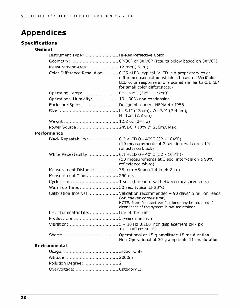
General Instrument Type: ........................ Hi-Res Reflective Color
Geometry: ................................. 0°/30° or 30°/0° (results below based on 30°/0°)
Measurement Area: ..................... 12 mm (.5 in.)
Color Difference Resolution ........... 0.25 ΔLED, typical (ΔLED is a proprietary color difference calculation which is based on VeriColor LED color response and is scaled similar to CIE ΔE* for small color differences.)
Operating Temp: ......................... 0° - 50°C (32° – 122°F)1
Operational Humidity: .................. 10 - 90% non condensing
Enclosure Spec: .......................... Designed to meet NEMA 4 / IP56
Size .......................................... L: 5.1” (13 cm), W: 2.9” (7.4 cm), H: 1.3” (3.3 cm)
Weight ...................................... 12.2 oz (347 g)
Power Source ............................. 24VDC ±10% @ 250mA Max.
Performance
Black Repeatability: ..................... 0.3 ΔLED 0 - 40°C (32 - 104°F)1 (10 measurements at 3 sec. intervals on a 1% reflectance black)
White Repeatability: .................... 0.1 ΔLED 0 - 40°C (32 - 104°F)1 (10 measurements at 3 sec. intervals on a 99% reflectance white)
Measurement Distance ................. 35 mm ±5mm (1.4 in. ±.2 in.)
Measurement Time: ..................... 250 ms
Cycle Time: ................................ 1 sec. (time interval between measurements)
Warm up Time: ........................... 30 sec. typical @ 23°C
Calibration Interval: .................... Validation recommended – 90 days/.5 million reads (whichever comes first) NOTE: More frequent verifications may be required if cleanliness of the system is not maintained.
LED Illuminator Life: .................... Life of the unit
Product Life: ............................... 5 years minimum
Vibration:................................... 5 – 10 Hz 0.200 inch displacement pk - pk 10 – 100 Hz at 1G
Shock: ....................................... Operational at 15 g amplitude 18 ms duration Non-Operational at 30 g amplitude 11 ms duration
Environmental Usage: ...................................... Indoor Only
Altitude: .................................... 2000m
Pollution Degree: ........................ 2
Overvoltage: .............................. Category II
V E R I C O L O R ® S O L O I D E N T I F I C A T I O N S Y S T E M
31
Safety Compliance
Underwriters Laboratories: ........... UL 61010-1
Canadian Standards Assoc: .......... CSA 22.2 No. 1010.1-92
International Electrotechnical
Committee ................................. IEC (EN) 61010-1 1When operating in environments above 40°C, the instrument should be calibrated and standards should be learned at the operating temperature to maintain best performance and color resolution.
Design and specifications subject to change without notice.
Accessories The following accessory items can be purchased from X-Rite by calling 1 800 248 9748 or by visiting our website at: www.xrite.com.
5 Meter Female – Open Ended Cable (8 circuit)/DB9 P/N VCS50-EUR8-5DB
5 Meter Male – Open Ended Cable (8 circuit) P/N SE108-EUR8-5M
1 Meter – Interconnect Cable (8 circuit) P/N SE108-EUR8-1
3 Meter – Interconnect Cable (8 circuit) P/N SE108-EUR8-3
10 Meter – Interconnect Cable (8 circuit) P/N SE108-EUR8-10
1 Meter – Right-angle Interconnect Cable (8 circuit) P/N SE108-EUR8-1RA Medium Spot (.50”) Targeting Sticker Kit P/N VC50-32
Medium Spot Solo Instrument P/N VCS50
V E R I C O L O R ® S O L O I D E N T I F I C A T I O N S Y S T E M
32
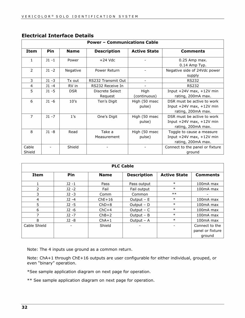
Electrical Interface Details Power – Communications Cable
Item Pin Name Description Active State Comments
1 J1 -1 Power +24 Vdc - 0.25 Amp max. 0.14 Amp Typ.
2 J1 -2 Negative Power Return - Negative side of 24Vdc power supply
3 J1 -3 Tx out RS232 Transmit Out - RS232 4 J1 -4 RV in RS232 Receive In - RS232 5 J1 -5 DSR Discrete Select
Request High
(continuous) Input +24V max, +12V min
rating, 200mA max. 6 J1 -6 10’s Ten’s Digit High (50 msec
pulse) DSR must be active to work Input +24V max, +12V min
rating, 200mA max. 7 J1 -7 1’s One’s Digit High (50 msec
pulse) DSR must be active to work Input +24V max, +12V min
rating, 200mA max. 8 J1 -8 Read Take a
Measurement High (50 msec
pulse) Toggle to cause a measure Input +24V max, +12V min
rating, 200mA max. Cable Shield
- Shield - - Connect to the panel or fixture ground
PLC Cable
Item Pin Name Description Active State Comments
1 J2 -1 Pass Pass output * 100mA max 2 J2 -2 Fail Fail output * 100mA max 3 J2 -3 Comm Common ** - 4 J2 -4 ChE+16 Output – E * 100mA max 5 J2 -5 ChD+8 Output – D * 100mA max 6 J2 -6 ChC+4 Output – C * 100mA max 7 J2 -7 ChB+2 Output – B * 100mA max 8 J2 -8 ChA+1 Output – A * 100mA max
Cable Shield - Shield - - Connect to the panel or fixture
ground
Note: The 4 inputs use ground as a common return.
Note: ChA+1 through ChE+16 outputs are user configurable for either individual, grouped, or even “binary” operation.
*See sample application diagram on next page for operation.
** See sample application diagram on next page for operation.

V E R I C O L O R ® S O L O I D E N T I F I C A T I O N S Y S T E M
33
External Connection – Sample Application
Option A (High Side Common)
Output A
Output E
Pass or FailOutput
Solo Instrument
+24VdcComm
Out A
Out E
Pass
LED
LED
LED
GND
GND
GND
Option B (Low Side Common)
Output A
Output E
Pass or FailOutput
Solo Instrument
+24Vdc
Comm
Out A
Out E
Fail
LED
LED
LED
GND
+24Vdc
+24Vdc
V E R I C O L O R ® S O L O I D E N T I F I C A T I O N S Y S T E M
34


Corporate Headquarters X-Rite, Incorporated 4300 44th Street SE Grand Rapids, Michigan 49512 Phone 1 800 248 9748 or 1 616 803 2100 Fax 1 800 292 4437 or 1 616 803 2705 European Headquarters X-Rite Europe GmbH Althardstrasse 70 8105 Regensdorf Switzerland Phone (+41) 44 842 24 00 Fax (+41) 44 842 22 22 Asia Pacific Headquarters X-Rite Asia Pacific Limited 36th Floor, No. 169 Electric Road Hong Kong, China Phone (852) 2568 6283 Fax (852) 2885 8610 Please visit www.xrite.com for a local office near you.
P/N VCS50-500 Rev. G