solo/solo dl user manual - aim sportsystems man… · user manual release 1.00 1 ... appendix –...
TRANSCRIPT

SOLO/SOLO DL
User manual
Solo-SoloDL User Manual Release 1.00
1 www.aim-sportline.com
Index
Chapter 1 – Included items and optional accessories .................................................... 3 1.1 – Optional accessories ........................................................................................................................ 5
Chapter 2 – Solo at a glance ............................................................................................. 6 2.1 – Display, buttons, GPS, USB port, connectors, and mounting points ........................................... 6 2.2 – Solo working modes .......................................................................................................................... 9
Chapter 3 – Installing and powering Solo ...................................................................... 10 3.1 – Bracket mounting ............................................................................................................................. 10 3.2 – Powering Solo/SoloDL ..................................................................................................................... 10
3.2.1 – Solo/SoloDL internally powered and battery charging ................................................................ 10 3.2.2 – Solo externally powered through the vehicle’s battery via 12V socket or cigarette lighter socket ................................................................................................................................................................ 10
3.3 – ECU connection – (SoloDL only) .................................................................................................... 11 Chapter 4 – Solo/SoloDL at powering on ....................................................................... 12
4.1 – Logger power on/off ......................................................................................................................... 12 4.2 – First time power on .......................................................................................................................... 12 4.3 – Sampling GPS signal ....................................................................................................................... 13
Chapter 5 – Solo configuration ....................................................................................... 14 5.1 – Lap timing modes ............................................................................................................................. 14
5.1.1 – Speed .......................................................................................................................................... 14 5.1.2 – Regularity .................................................................................................................................... 14 5.1.3 – Performance tests in detail ......................................................................................................... 14
5.2 – Circuits: Closed and Open .............................................................................................................. 14 5.1.1 – Closed circuit .............................................................................................................................. 14 5.1.2 – Open circuit ................................................................................................................................. 14
5.3 – Configuration Pages ........................................................................................................................ 15 5.4 – Units of Measure selection .............................................................................................................. 16 5.5 – Auto power off .................................................................................................................................. 16 5.6 – Time zone and time/date format settings ...................................................................................... 16 5.7 – System information .......................................................................................................................... 16
Chapter 6 – Race Studio Software.................................................................................. 17 6.2 – Software installation ........................................................................................................................ 17 6.3 – SoloDL configuration ....................................................................................................................... 17
Chapter 7 – Track management ...................................................................................... 18 7.1 Adding Starting Line Coordinates directly to Solo .......................................................................... 18 7.2 – Track Management functions in Race Studio 2 ............................................................................ 19
Chapter 8 – Use of Solo during tests ............................................................................. 20 8.1 – Closed circuit – speed races ........................................................................................................... 20 8.2 – Closed circuit – regularity races ..................................................................................................... 20 8.3 – Open circuit – speed races ............................................................................................................. 20 8.4 – Performance tests ............................................................................................................................ 20
Chapter 9 – Data Recall ................................................................................................... 21 9.1 – Data recall ......................................................................................................................................... 21 9.2 – Data in Memory deletion .................................................................................................................. 21
Chapter 10 – Data download to the PC and Data Analysis through Race Studio2 .... 22 10.1 Data Download .................................................................................................................................. 22 10.2 Data Analysis ..................................................................................................................................... 22
Chapter 11 – Connection with SmartyCam (SoloDL only) ........................................... 23 11.1 – Physical Connection ...................................................................................................................... 24 11.2 – SoloDL configuration of the data stream to SmartyCam ........................................................... 24 11.3 – Interaction with SmartyCam .......................................................................................................... 25
Chapter 12 – Upgrading Solo firmware .......................................................................... 26 Appendix – Loggers pinout ............................................................................................ 27
Solo-SoloDL User Manual Release 1.00
2 www.aim-sportline.com
Introduction
What is Solo? Solo is an automatic lap timer based on GPS technology.
What does it do?Solo has a database with a list of the main world tracks. When the Solo is powered on, it locates its GPS position, loads the track lap coordinates and starts, automatically sampling lap times.
If the track is not in the database? It can be easily added (further details in this manual).
Types of tracks? Motor sport is very diversified: there are circuit races, hill climb racing, regularity races, tests with starting and finishing points in different positions, performance tests. Solo is designed for all situations with a simple keyboard configuration.
What are the differences in managing all specialties? The working mode is different according to the kind of circuit, closed or open, and the type of race, that can be speed race (the winner is the fastest) or regularity race (a lap time is set as reference and the difference between the current lap and the reference one is always shown). Also are the acceleration races: computation and memorisation starts when the speed grows and stops according to the settings.
What else? Solo records other figures also, and you will not need a track engineer, nor complicated sensors, connections or expensive wirings. This small unit records important figures: instant racing speed, braking, route, accelerations… Details can seen while racing. Afterwards you can review the race records, it is useful to review what really happened. The space for an improvement is always available.
Is there more? Solo stops here. But he as a brother, SoloDL. SoloDL does everything that Solo does, but can also be connected to the ECU to read and record data coming from the engine. The two systems share the same logic: maximum amount of information with minimum effort. ECU connection is really very simple, and the information available is very useful.
Who wants more? You can connect SoloDL to SmartyCam, AIM on board camera, and then you have a Video with high precision figures.
And even more? AIM has followed professional drivers and high level teams, for a very long time. Car manufacturers like Renault, Seat, Mazda, Ford… use and have used AIM systems in many championships. You will surely find what you need in our catalogue, but it is not Solo!
Solo-SoloDL User Manual Release 1.00
3 www.aim-sportline.com
Chapter 1 – Included items and optional accessories
What will be inside the box?
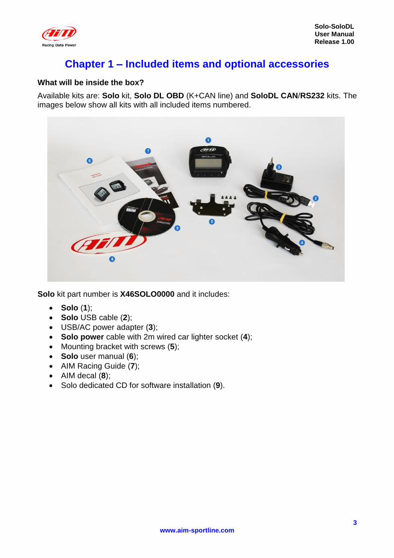
Available kits are: Solo kit, Solo DL OBD (K+CAN line) and SoloDL CAN/RS232 kits. The images below show all kits with all included items numbered.
Solo kit part number is X46SOLO0000 and it includes:
Solo (1);
Solo USB cable (2);
USB/AC power adapter (3);
Solo power cable with 2m wired car lighter socket (4);
Mounting bracket with screws (5);
Solo user manual (6);
AIM Racing Guide (7);
AIM decal (8);
Solo dedicated CD for software installation (9).

Solo-SoloDL User Manual Release 1.00
4 www.aim-sportline.com
SoloDL OBDII (K Line/CAN) part number is X46SOLODLKC and it includes:
SoloDL (1)
USB cable (2)
USB/AC power adapter (3)
2m OBDII/power cable (4)
Mounting bracket with screws (5)
User manual (6)
AIM Racing Guide (7)
AIM decal (8)
Software installation CD (9)
SoloDL (CAN/RS232) part number is X46SOLODLCR and it includes:
SoloDL (1)
USB cable (2)
USB/AC power adapter (3)
4m CAN/RS232 ECU harness (4)
Mounting bracket with screws (5)
User manual (6)
AIM Racing Guide (7)
AIM decal (8)
Software installation CD (9)

Solo-SoloDL User Manual Release 1.00
5 www.aim-sportline.com
1.1 – Optional accessories
Solo can be installed in a variety of ways depending on the application and your preferences. Outlined below are several mounting options available for application-specific installations:
Suction cup bracket kit with screws
Handlebar bracket kit accommodating bars from 0.5” to 2.0’’ diameter.
Double bar bracket kit with U bolt for bars from 0.75’’ to 1.25’’ diameter
Metallic wrap for pipes from 1.57’’ to 3.15’’ diameter
Solo-SoloDL User Manual Release 1.00
6 www.aim-sportline.com
Chapter 2 – Solo at a glance
Understanding Solo..
Solo’smost important feature is to show your Lap Times. The calculation is done using the GPS position of your vehicle and the track starting line. Solo calculates the position of your vehicle ten times per second, and interpolates the nearest position to the starting line for very high precision.
Of course, for obtain lap Times, Solo has to know the Starting Line Coordinates. This can be done in three different ways:
Solo comes with a wide database of many tracks of the world. You can check them pressing “>>>” until the page below on the left appears; pressing “VIEW” button you enter the page shown on the right;
You can define the starting point of the track by going to the starting line and setting the desired point. In chapter 8.1 of this tutorial you will read how to do this.
You can define the same starting point by the Track Manager feature of Aim software Race Studio 2. In chapter 8.2 of this tutorial you will read how to do this.
Please, take note that if you run in an Open Circuit, i.e. a track with starting and finish line in different positions, you have to define TWO different points: Start and Finish.
Finally, if you run a Performance Test, like a “Drag” acceleration, no starting point coordinates are needed: just push your throttle and go. Solo will start and stop the test automatically.
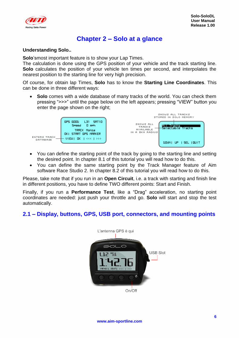
2.1 – Display, buttons, GPS, USB port, connectors, and mounting points
Solo-SoloDL User Manual Release 1.00
7 www.aim-sportline.com
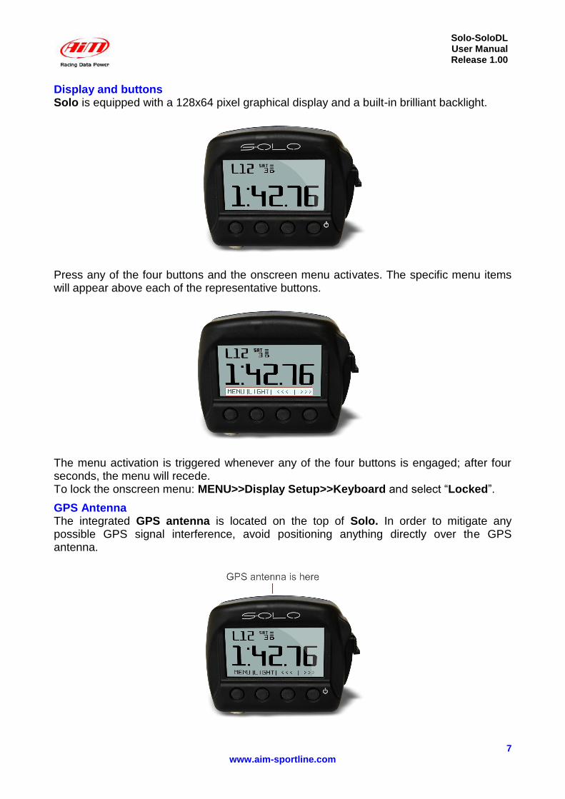
Display and buttons Solo is equipped with a 128x64 pixel graphical display and a built-in brilliant backlight.
Press any of the four buttons and the onscreen menu activates. The specific menu items will appear above each of the representative buttons.
The menu activation is triggered whenever any of the four buttons is engaged; after four seconds, the menu will recede. To lock the onscreen menu: MENU>>Display Setup>>Keyboard and select “Locked”.
GPS Antenna The integrated GPS antenna is located on the top of Solo. In order to mitigate any possible GPS signal interference, avoid positioning anything directly over the GPS antenna.

Solo-SoloDL User Manual Release 1.00
8 www.aim-sportline.com
USB Port To access the USB port, slide the lock on the waterproof USB door down and the door will open revealing the port. Solo uses USB for:
charging
configuration
data download
and firmware upgrades
Connectors Solo features a single connector located on the bottom, which is used when powering the system from a 12V source.
SoloDL features two connectors on the bottom of the system: one to connect to an external CAN expansion (for example SmartyCam – see Chapter 11) and the second is used for ECU connection and power (bottom right image). Please, take note that the external power can be received from the first or the second connector.
Solo-SoloDL User Manual Release 1.00
9 www.aim-sportline.com
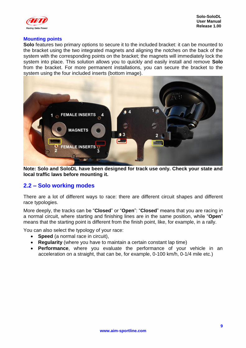
Mounting points Solo features two primary options to secure it to the included bracket: it can be mounted to the bracket using the two integrated magnets and aligning the notches on the back of the system with the corresponding points on the bracket; the magnets will immediately lock the system into place. This solution allows you to quickly and easily install and remove Solo from the bracket. For more permanent installations, you can secure the bracket to the system using the four included inserts (bottom image).
Note: Solo and SoloDL have been designed for track use only. Check your state and local traffic laws before mounting it.
2.2 – Solo working modes
There are a lot of different ways to race: there are different circuit shapes and different race typologies.
More deeply, the tracks can be “Closed” or “Open”: “Closed” means that you are racing in a normal circuit, where starting and finishing lines are in the same position, while “Open” means that the starting point is different from the finish point, like, for example, in a rally.
You can also select the typology of your race:
Speed (a normal race in circuit),
Regularity (where you have to maintain a certain constant lap time)
Performance, where you evaluate the performance of your vehicle in an acceleration on a straight, that can be, for example, 0-100 km/h, 0-1/4 mile etc.)
Solo-SoloDL User Manual Release 1.00
10 www.aim-sportline.com
Chapter 3 – Installing and powering Solo
Solo can be internally or externally powered and can be installed using different supports whose codes are reported in chapter 1.
3.1 – Bracket mounting
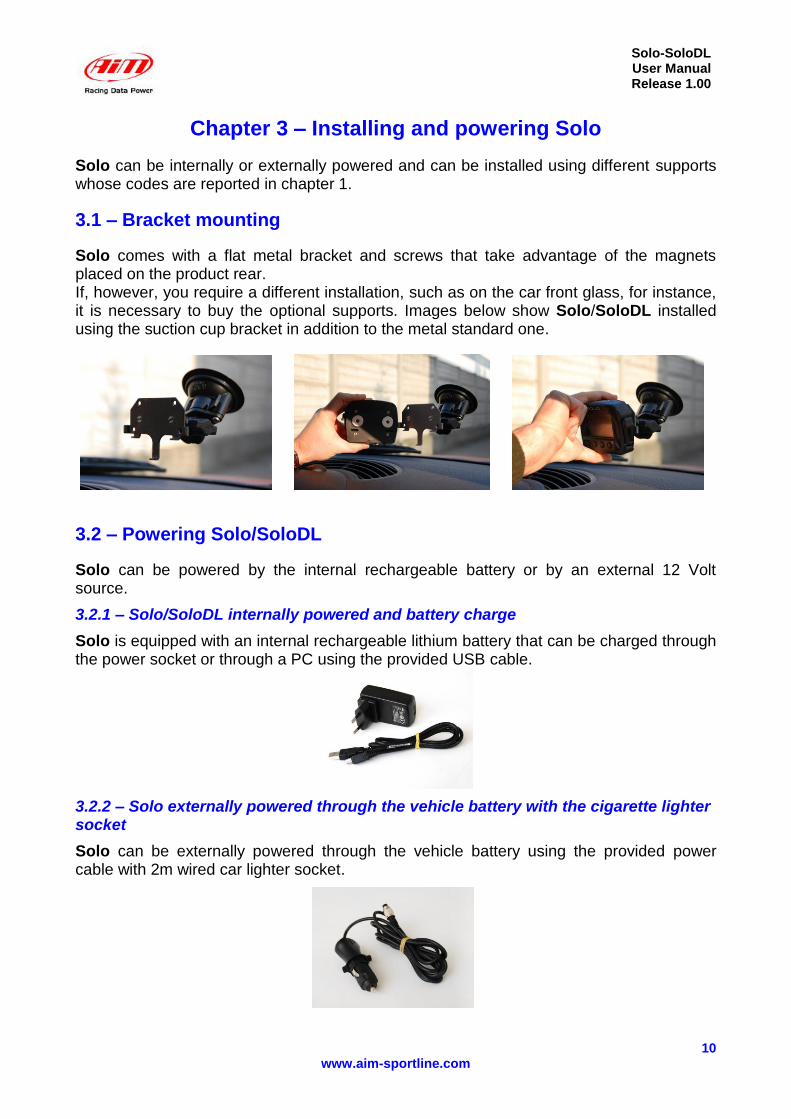
Solo comes with a flat metal bracket and screws that take advantage of the magnets placed on the product rear. If, however, you require a different installation, such as on the car front glass, for instance, it is necessary to buy the optional supports. Images below show Solo/SoloDL installed using the suction cup bracket in addition to the metal standard one.
3.2 – Powering Solo/SoloDL
Solo can be powered by the internal rechargeable battery or by an external 12 Volt source.
3.2.1 – Solo/SoloDL internally powered and battery charge
Solo is equipped with an internal rechargeable lithium battery that can be charged through the power socket or through a PC using the provided USB cable.
3.2.2 – Solo externally powered through the vehicle battery with the cigarette lighter socket
Solo can be externally powered through the vehicle battery using the provided power cable with 2m wired car lighter socket.
Solo-SoloDL User Manual Release 1.00
11 www.aim-sportline.com
3.3 – ECU connection – SoloDL only
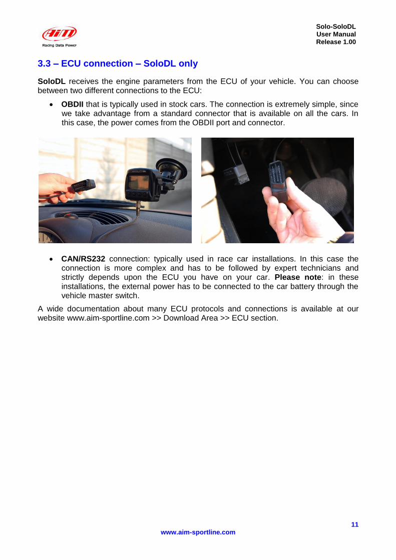
SoloDL receives the engine parameters from the ECU of your vehicle. You can choose between two different connections to the ECU:
OBDII that is typically used in stock cars. The connection is extremely simple, since we take advantage from a standard connector that is available on all the cars. In this case, the power comes from the OBDII port and connector.
CAN/RS232 connection: typically used in race car installations. In this case the connection is more complex and has to be followed by expert technicians and strictly depends upon the ECU you have on your car. Please note: in these installations, the external power has to be connected to the car battery through the vehicle master switch.
A wide documentation about many ECU protocols and connections is available at our website www.aim-sportline.com >> Download Area >> ECU section.
Solo-SoloDL User Manual Release 1.00
12 www.aim-sportline.com
Chapter 4 – Solo/SoloDL powering on
4.1 – Logger power on/off
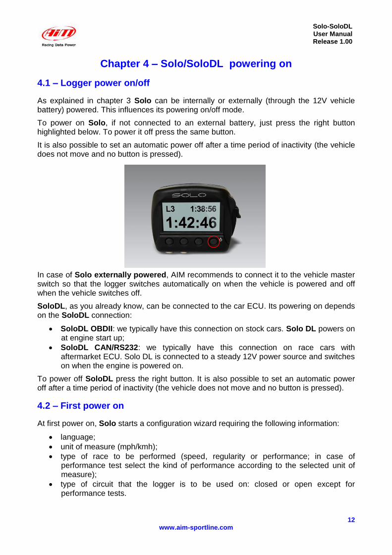
As explained in chapter 3 Solo can be internally or externally (through the 12V vehicle battery) powered. This influences its powering on/off mode.
To power on Solo, if not connected to an external battery, just press the right button highlighted below. To power it off press the same button.
It is also possible to set an automatic power off after a time period of inactivity (the vehicle does not move and no button is pressed).
In case of Solo externally powered, AIM recommends to connect it to the vehicle master switch so that the logger switches automatically on when the vehicle is powered and off when the vehicle switches off.
SoloDL, as you already know, can be connected to the car ECU. Its powering on depends on the SoloDL connection:
SoloDL OBDII: we typically have this connection on stock cars. Solo DL powers on at engine start up;
SoloDL CAN/RS232: we typically have this connection on race cars with aftermarket ECU. Solo DL is connected to a steady 12V power source and switches on when the engine is powered on.
To power off SoloDL press the right button. It is also possible to set an automatic power off after a time period of inactivity (the vehicle does not move and no button is pressed).
4.2 – First power on
At first power on, Solo starts a configuration wizard requiring the following information:
language;
unit of measure (mph/kmh);
type of race to be performed (speed, regularity or performance; in case of performance test select the kind of performance according to the selected unit of measure);
type of circuit that the logger is to be used on: closed or open except for performance tests.
Solo-SoloDL User Manual Release 1.00
13 www.aim-sportline.com
4.3 – Sampling GPS signal
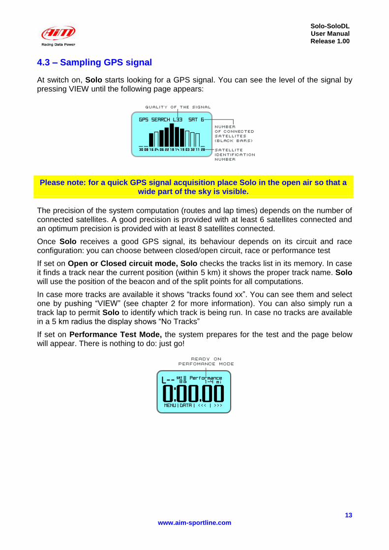
At switch on, Solo starts looking for a GPS signal. You can see the level of the signal by pressing VIEW until the following page appears:
Please note: for a quick GPS signal acquisition place Solo in the open air so that a wide part of the sky is visible.
The precision of the system computation (routes and lap times) depends on the number of connected satellites. A good precision is provided with at least 6 satellites connected and an optimum precision is provided with at least 8 satellites connected.
Once Solo receives a good GPS signal, its behaviour depends on its circuit and race configuration: you can choose between closed/open circuit, race or performance test
If set on Open or Closed circuit mode, Solo checks the tracks list in its memory. In case it finds a track near the current position (within 5 km) it shows the proper track name. Solo will use the position of the beacon and of the split points for all computations.
In case more tracks are available it shows “tracks found xx”. You can see them and select one by pushing “VIEW” (see chapter 2 for more information). You can also simply run a track lap to permit Solo to identify which track is being run. In case no tracks are available in a 5 km radius the display shows “No Tracks”
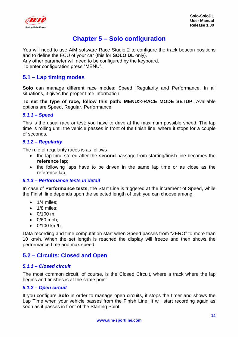
If set on Performance Test Mode, the system prepares for the test and the page below will appear. There is nothing to do: just go!
Solo-SoloDL User Manual Release 1.00
14 www.aim-sportline.com
Chapter 5 – Solo configuration
You will need to use AiM software Race Studio 2 to configure the track beacon positions and to define the ECU of your car (this for SOLO DL only). Any other parameter will need to be configured by the keyboard. To enter configuration press “MENU”.
5.1 – Lap timing modes
Solo can manage different race modes: Speed, Regularity and Performance. In all situations, it gives the proper time information.
To set the type of race, follow this path: MENU>>RACE MODE SETUP. Available options are Speed, Regular, Performance.
5.1.1 – Speed
This is the usual race or test: you have to drive at the maximum possible speed. The lap time is rolling until the vehicle passes in front of the finish line, where it stops for a couple of seconds.
5.1.2 – Regularity
The rule of regularity races is as follows
the lap time stored after the second passage from starting/finish line becomes the reference lap;
the following laps have to be driven in the same lap time or as close as the reference lap.
5.1.3 – Performance tests in detail
In case of Performance tests, the Start Line is triggered at the increment of Speed, while the Finish line depends upon the selected length of test: you can choose among:
1/4 miles;
1/8 miles;
0/100 m;
0/60 mph;
0/100 km/h.
Data recording and time computation start when Speed passes from “ZERO” to more than 10 km/h. When the set length is reached the display will freeze and then shows the performance time and max speed.
5.2 – Circuits: Closed and Open
5.1.1 – Closed circuit
The most common circuit, of course, is the Closed Circuit, where a track where the lap begins and finishes is at the same point.
5.1.2 – Open circuit
If you configure Solo in order to manage open circuits, it stops the timer and shows the Lap Time when your vehicle passes from the Finish Line. It will start recording again as soon as it passes in front of the Starting Point.
Solo-SoloDL User Manual Release 1.00
15 www.aim-sportline.com
5.3 – Configuration pages
What can I see during my test? We have already seen that there is a good amount of information that you can see on your display, while your vehicle is on the track:
lap time;
predictive lap time;
speed;
lap number;
acceleration;
GPS signal information;
and, for SOLO DL only, all the information coming from the engine.
Now, the question is: how can we select what we want to see? It is really very easy: SOLO has some pre-defined pages, showing pre-organised fields.
You can easily change the screens by pushing “VIEW”.
Also, you can configure other pages (up to 4), called “Custom Pages”.
You will also notice that every page can be enabled or disabled: so, if you need only two pages, you can swap between them, pushing VIEW. If you need to see more information, you have to enable more pages.
To set the pages follow this path: “MENU”>> “Display Setup”>> “Pages Setup” >> “Enable/Disable Pages” and enable/disable the pages to be shown.
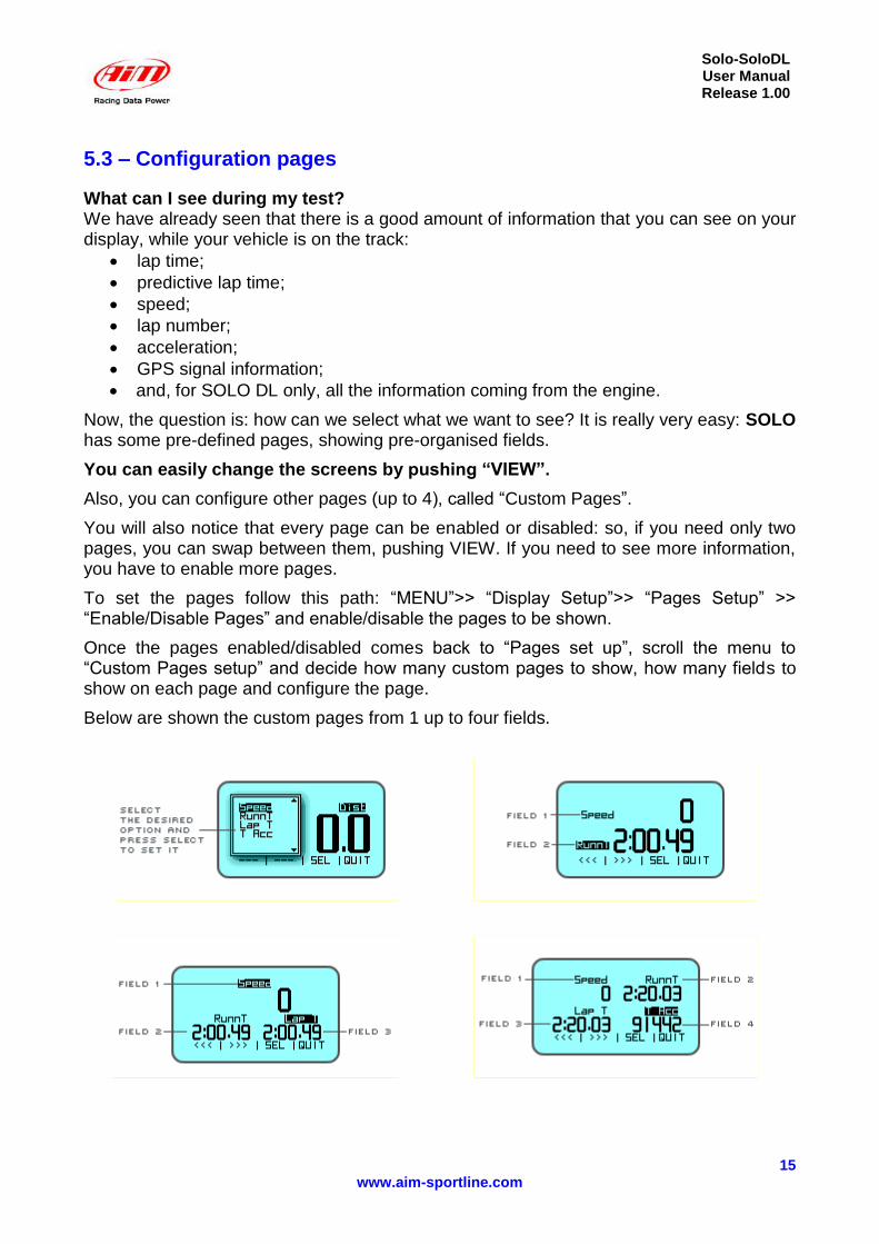
Once the pages enabled/disabled comes back to “Pages set up”, scroll the menu to “Custom Pages setup” and decide how many custom pages to show, how many fields to show on each page and configure the page.
Below are shown the custom pages from 1 up to four fields.

Solo-SoloDL User Manual Release 1.00
16 www.aim-sportline.com
5.4 – Units of Measure selection
Solo/Solo DL can compute using Decimal or Imperial units of measure. To set the units of measure, follow this path: MENU>>Set Units and select the Unit of Measure required.
5.5 – Auto power off
Solo automatically powers off after 5 minutes of inactivity (no movement and no button pressed).
5.6 – Time zone and time/date format settings
Solo can show the date and time in different formats enabling or not legal time. Follow this path MENU>>Set Time/Date and set:
Actual Local Time;
Legal time: OFF/ON;
Time format: 24h or 12h;
Date format: to be selected among: DD/MM/YY, MM/DD/YY OR YY/MM/DD.
5.7 – System information
This page shows logger firmware version and serial number. Follow this path: MENU >> System Information and this page will appear.
Solo-SoloDL User Manual Release 1.00
17 www.aim-sportline.com
Chapter 6 – Race Studio Software
Race Studio 2 software will need to be used for the following activities:
upgrading the track list database
downloading the test data
analyzing the test data
Aim constantly upgrades Race Studio 2 software. Each new release is available free to download from our web site www.aim-sportline.com, download Area/Software section.
Please note: Race Studio 2 software minimal required version to configure and download data from Solo is: 2.43.01.
6.2 – Software installation
To install Race Studio 2 software just place the CD in the proper driver and wait for a few seconds. The system will show three windows that ask the user:
to select the language;
to choose if reading the documentation or installing a software: select the second option;
which software to install: select Race Studio 2: the installation will start automatically.
6.3 – SoloDL configuration
SoloDL logger can be connected to the vehicle’s ECU and consequently configured using Race Studio 2; refer to AIM website www.aim-sportline.com >> “ECU connection” area to know which ECUs are currently supported by AIM devices.
Once you have verified that the vehicle ECU is supported’, just follow this procedure with SoloDL switched on and connected to the PC:
run Race Studio 2 software;
click on “AIM system manager”;
press “New” button and “New Configuration” window appears;
data logger type is already set;
select ECU Manufacturer and model;
enter configuration and vehicle name;
choose the units of measure
press “OK”.
only in case the ECU does not transmit the engaged gear activate “System configuration” logger and set “calculated” gears;
press transmit.
Solo-SoloDL User Manual Release 1.00
18 www.aim-sportline.com
Chapter 7 – Track management
How do I send lap and split coordinates of the track to my SOLO?
We have already underlined that Solo comes with a wide database of starting line / split line coordinates.
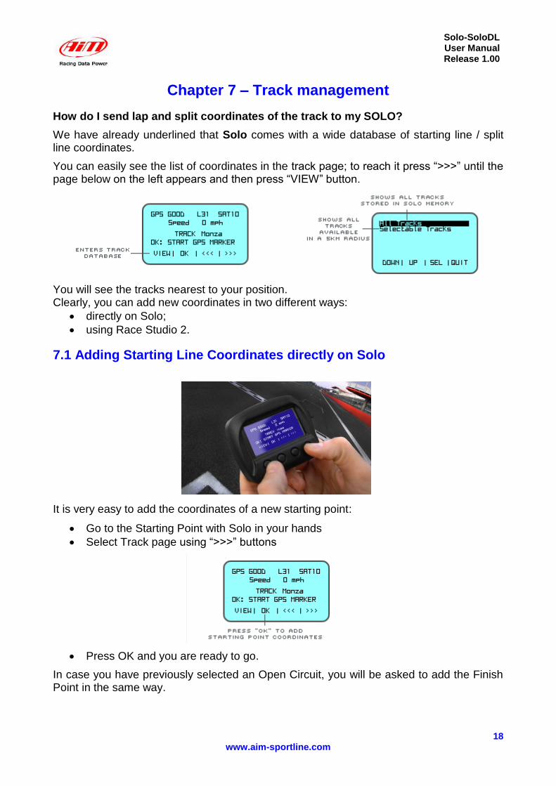
You can easily see the list of coordinates in the track page; to reach it press “>>>” until the page below on the left appears and then press “VIEW” button.
You will see the tracks nearest to your position. Clearly, you can add new coordinates in two different ways:
directly on Solo;
using Race Studio 2.
7.1 Adding Starting Line Coordinates directly on Solo
It is very easy to add the coordinates of a new starting point:
Go to the Starting Point with Solo in your hands
Select Track page using “>>>” buttons
Press OK and you are ready to go.
In case you have previously selected an Open Circuit, you will be asked to add the Finish Point in the same way.
Solo-SoloDL User Manual Release 1.00
19 www.aim-sportline.com
7.2 – Track Management function in Race Studio 2
You can have full management of the track database, you are free to add or remove track information.
To do so, you have to use the “Track Management” feature of our software Race Studio 2, after having turned on your Solo and having connected it to your PC
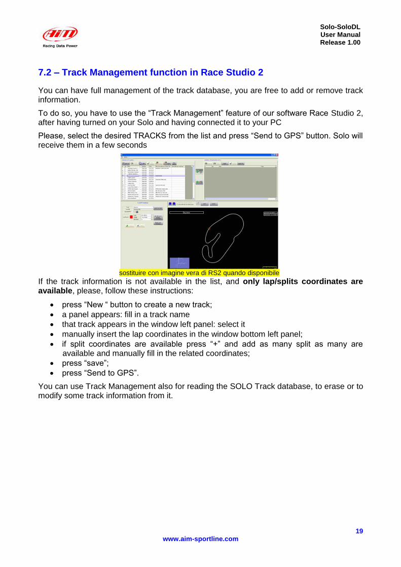
Please, select the desired TRACKS from the list and press “Send to GPS” button. Solo will receive them in a few seconds
sostituire con imagine vera di RS2 quando disponibile
If the track information is not available in the list, and only lap/splits coordinates are available, please, follow these instructions:
press “New “ button to create a new track;
a panel appears: fill in a track name
that track appears in the window left panel: select it
manually insert the lap coordinates in the window bottom left panel;
if split coordinates are available press “+” and add as many split as many are available and manually fill in the related coordinates;
press “save”;
press “Send to GPS”.
You can use Track Management also for reading the SOLO Track database, to erase or to modify some track information from it.
Solo-SoloDL User Manual Release 1.00
20 www.aim-sportline.com
Chapter 8 – Use of Solo during the tests
How does SOLO work when I race…
Solo behaves differently according to its settings.
First of all, we have to know that SOLO starts recording when the speed increases. So, if the vehicle does not move, even with the engine ON, Solo does not do anything, you can normally enter the Menu etc. When Speed reaches 20 km/h, SOLO changes mode and starts recording all the parameters.
Also it may be useful to know that SOLO has a preliminary buffer, so it can really start saving information ONE SECOND BEFORE the start of the race. This can be extremely useful to analyse the very first instants of the race.
8.1 – Closed circuit – speed races
As we have already seen, there are three types of Lap time information that we can see:
Rolling Lap Time, that is shown by default
Steady lap Time, that appears for some seconds at the starting line
Predictive Lap Time, that is shown on Page 2 and that is evaluated after having finished the first lap
With “>>>/<<<” buttons it switches from one page to the other, according to the number of configured pages. At the end it shows the satellite page.
8.2 – Closed circuit – regularity races
As in Speed Races, Solo shows Rolling, Steady and Predictive lap time. The only difference is that it calculates the Predictive Lap Time referred to the speed of the Second Lap and shows the Predictive time difference between the Second lap and the Actual one.
At the Pit Stop, the vehicle….stops and, generally, SOLO is turned off. Nevertheless, it goes on evaluating the time and does not interrupt the recorded test, so, when the vehicle starts racing again, the lap time and lap number are not reset.
With “>>>/<<<” buttons it switches from one page to the other, according to the number of configured pages. At the end it shows the satellite page.
8.3 – Open circuit – speed races
Races in open circuit have a starting and a finishing point. Both points are stored in the track’s database. The display shows rolling lap time. At the end of the race, when the car crosses the finish line, the time becomes Steady.
8.4 – Performance tests
The vehicle places at the starting point, the car starts. That is it! On the dash you can see the rolling time that becomes Steady Time as soon as the Performance finishes, so, after ¼ of mile, or ½ mile, or when it gets 100 km/h etc. Maximum speed is shown also. Data recorded are, of course, speed every 1/10 of second, acceleration, time and, if you have a SoloDL, all the information coming from ECU. Very simple, very easy.
Solo-SoloDL User Manual Release 1.00
21 www.aim-sportline.com
Chapter 9 – Data Recall
How do I review my data after the test?
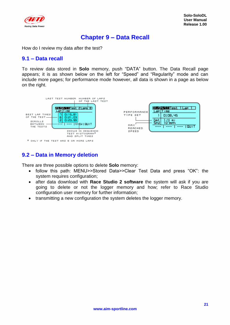
9.1 – Data recall
To review data stored in Solo memory, push “DATA” button. The Data Recall page appears; it is as shown below on the left for “Speed” and “Regularity” mode and can include more pages; for performance mode however, all data is shown in a page as below on the right.
9.2 – Data in Memory deletion
There are three possible options to delete Solo memory:
follow this path: MENU>>Stored Data>>Clear Test Data and press “OK”: the system requires configuration;
after data download with Race Studio 2 software the system will ask if you are going to delete or not the logger memory and how; refer to Race Studio configuration user memory for further information;
transmitting a new configuration the system deletes the logger memory.
Solo-SoloDL User Manual Release 1.00
22 www.aim-sportline.com
Chapter 10 – Data download on the PC and Data Analysis through Race Studio2
How can I use Solo for a professional data analysis?
If you wish to better understand your performance, you absolutely need to analyse your data on your PC. Only on a wide screen can you compare two laps, sector after sector, evaluate when and where you start braking and how fast you are in pushing the throttle.
For this analysis, you can take advantage of Aim highly professional software Race Studio 2. This software, (that comes free of charge with your Solo), is constantly upgraded by Aim engineers: every new release can be easily downloaded (free of charge) from the web site: www.aim-sportline.com “Download Area” Software section.
The first step is to download the recorded data on your PC.
10.1 Data Download
Data Downloading is very simple:
connect Solo to your PC
Run Race Studio 2
Click on “Download data” and follow the instructions.
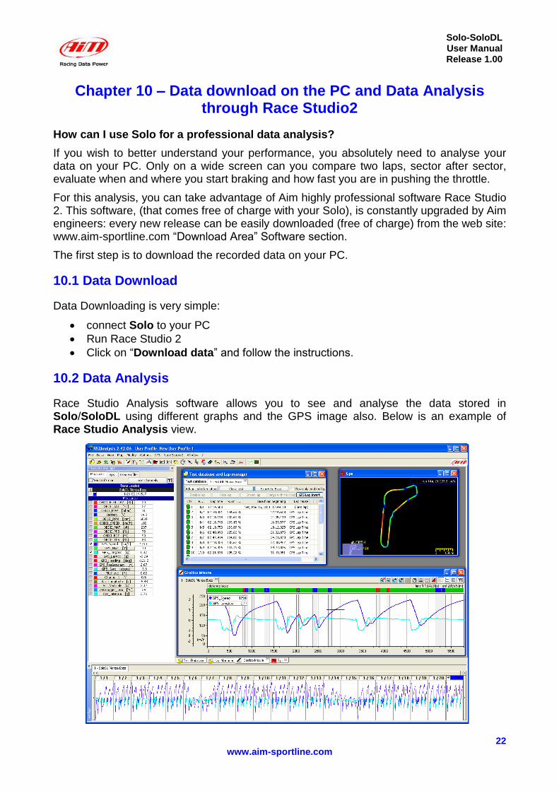
10.2 Data Analysis
Race Studio Analysis software allows you to see and analyse the data stored in Solo/SoloDL using different graphs and the GPS image also. Below is an example of Race Studio Analysis view.
Solo-SoloDL User Manual Release 1.00
23 www.aim-sportline.com
Chapter 11 – Connection with SmartyCam (SoloDL only)
How do I add videos to my data?
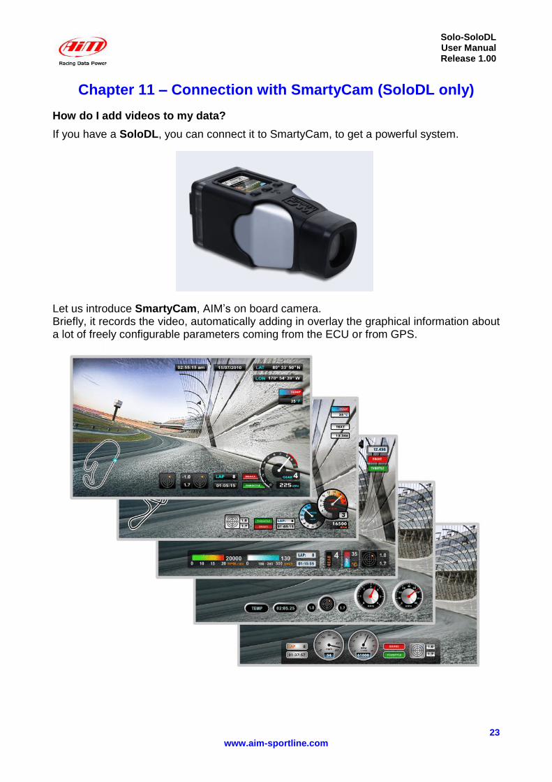
If you have a SoloDL, you can connect it to SmartyCam, to get a powerful system.
Let us introduce SmartyCam, AIM’s on board camera. Briefly, it records the video, automatically adding in overlay the graphical information about a lot of freely configurable parameters coming from the ECU or from GPS.

Solo-SoloDL User Manual Release 1.00
24 www.aim-sportline.com
So, the configuration Solo DL/SmartyCam is extremely synergic, since the two systems can take advantage of features from each other:
SmartyCam can read Solo DL parameters from ECU
SmartyCam can read Solo DL GPS and GPS lap time
SoloDL display can show information about SmartyCam Status, like the amount of free uSD memory, battery level, recording status, diagnostic messages etc.
SmartyCam can record SoloDL data on its uSD Card, for a quicker management of them. Later, on your PC, you can easily synchronise video and data.
11.1 – Physical Connection
To connect SoloDL with SmartyCam use the 5 pin CAN cable provided with SmartyCam.
11.2 – SoloDL configuration of the data stream to SmartyCam
To get data sampled by SoloDL visualised on SmartyCam videos, you have to take a maximum 16 channels among the data outcoming from the ECU and send them to SmartyCam. This is done using Race Studio 2 software. Follow this path: System Manager>>Solo>>>“SmartyCam functions setting” and the related panel shown below on the right appears.
It shows on the left the functions that can be visualised on the SmartyCam videos and on the right the ECU channels you can set that function on. Entering the drop down menu you can see some of the channels out coming from the ECU grouped by type (for instance on Water temp function you find all temperatures out coming from the ECU). If you find the channel you need, simply select it and associate it to SoloDL channel. Should the channel you want to set not appear in the list, enable the bottom checkbox to verify if that channel is provided by your ECU. Once all channels have been set press “Transmit” on top of the page and these channels will be automatically sent to SmartyCam.
Solo-SoloDL User Manual Release 1.00
25 www.aim-sportline.com
11.3 – Interaction with SmartyCam
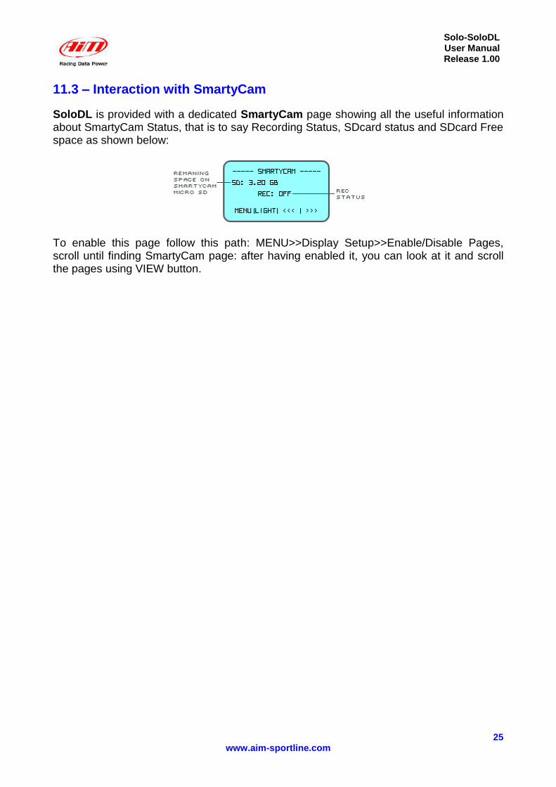
SoloDL is provided with a dedicated SmartyCam page showing all the useful information about SmartyCam Status, that is to say Recording Status, SDcard status and SDcard Free space as shown below:
To enable this page follow this path: MENU>>Display Setup>>Enable/Disable Pages, scroll until finding SmartyCam page: after having enabled it, you can look at it and scroll the pages using VIEW button.
Solo-SoloDL User Manual Release 1.00
26 www.aim-sportline.com
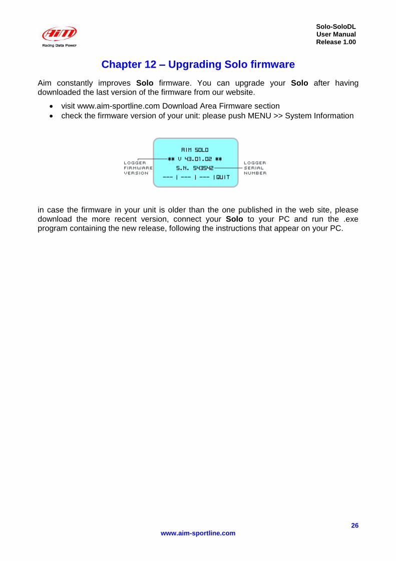
Chapter 12 – Upgrading Solo firmware
Aim constantly improves Solo firmware. You can upgrade your Solo after having downloaded the last version of the firmware from our website.
visit www.aim-sportline.com Download Area Firmware section
check the firmware version of your unit: please push MENU >> System Information
in case the firmware in your unit is older than the one published in the web site, please download the more recent version, connect your Solo to your PC and run the .exe program containing the new release, following the instructions that appear on your PC.
Solo-SoloDL User Manual Release 1.00
27 www.aim-sportline.com
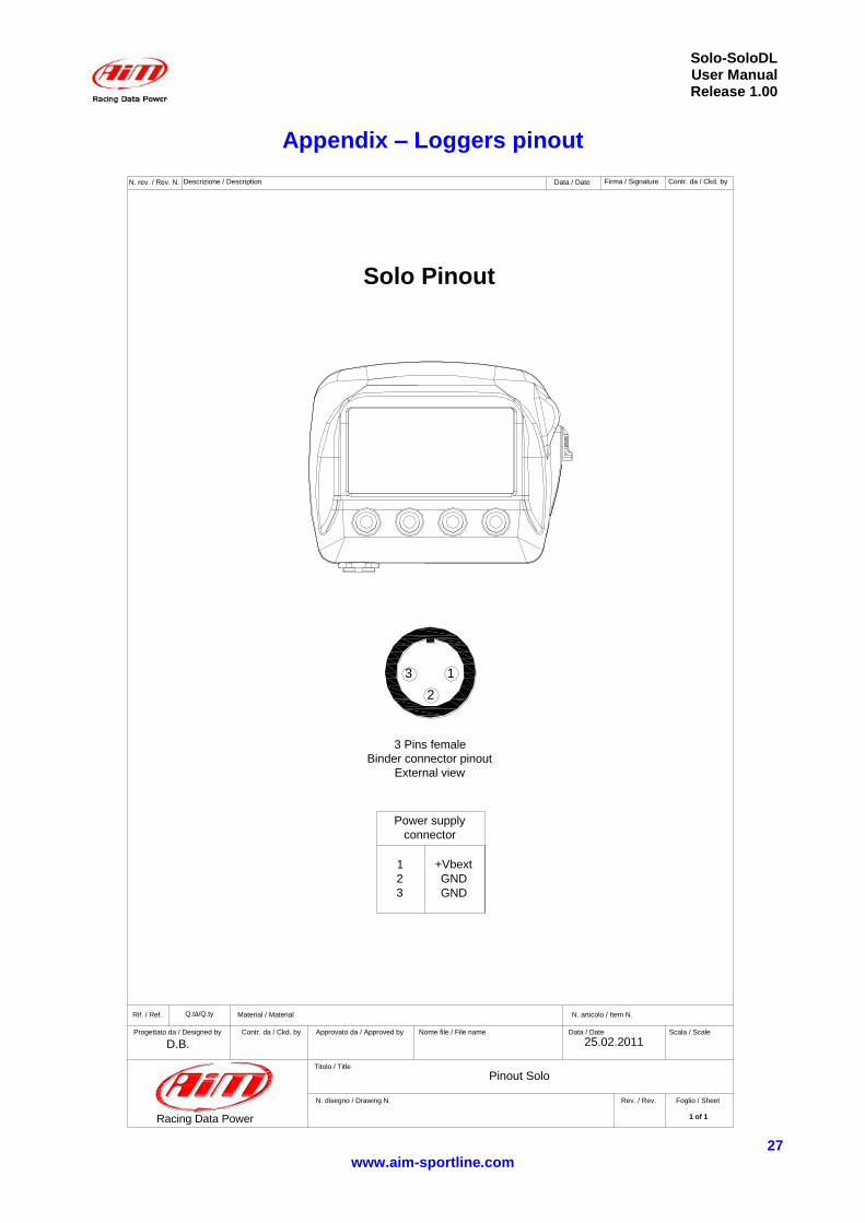
Appendix – Loggers pinout
2
13
Racing Data Power
N. rev. / Rev. N. Descrizione / Description Data / Date Firma / Signature Contr. da / Ckd. by
Rif. / Ref. Q.tà/Q.ty Material / Material N. articolo / Item N.
Progettato da / Designed by Contr. da / Ckd. by Approvato da / Approved by Nome file / File name Data / Date Scala / Scale
Titolo / Title
N. disegno / Drawing N. Rev. / Rev. Foglio / Sheet
Solo Pinout
3 Pins female
Binder connector pinout
External view
Power supply
connector
1
2
3
+Vbext
GND
GND
1 of 1
Pinout Solo
D.B. 25.02.2011
Solo-SoloDL User Manual Release 1.00
28 www.aim-sportline.com
45
2
1
3
6
7
4
5
2
1
3
Racing Data Power
N. rev. / Rev. N. Descrizione / Description Data / Date Firma / Signature Contr. da / Ckd. by
Rif. / Ref. Q.tà/Q.ty Material / Material N. articolo / Item N.
Progettato da / Designed by Contr. da / Ckd. by Approvato da / Approved by Nome file / File name Data / Date Scala / Scale
Titolo / Title
N. disegno / Drawing N. Rev. / Rev. Foglio / Sheet
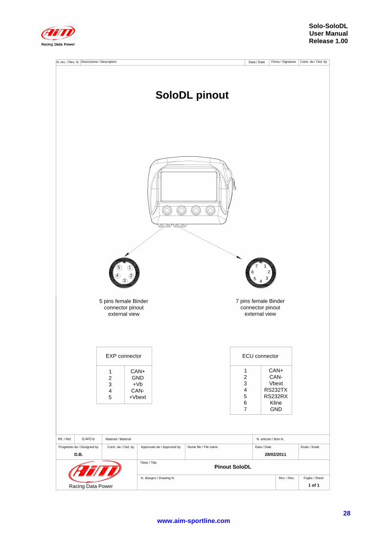
SoloDL pinout
5 pins female Binder
connector pinout
external view
EXP connector ECU connector
1
2
3
4
5
CAN+
GND
+Vb
CAN-
+Vbext
1
2
3
4
5
6
7
CAN+
CAN-
Vbext
RS232TX
RS232RX
Kline
GND
28/02/2011
1 of 1
D.B.
Pinout SoloDL
7 pins female Binder
connector pinout
external view