soltronic mppt · pdf fileseite 1 soltronic mppt 7520 instruction manual for solar charge...
TRANSCRIPT

Seite 1
Soltronic MPPT 7520Instruction Manual for Solar Charge RegulatorDear Customer,
we would like to thank you for purchasing a Soltronic product. By purchasing the new MPPT regulator, you have bought a devise that represents the state-of-the-art technology in the field.
Before the installation of the regulator, please consult carefully the instruction manual and take notice of the safety recommendations as outlined at the end of the manual.
ContentsGeneral Functional Characteristics........................................................................................ 2Details of Operation............................................................................................................... 2Mounting ............................................................................................................................... 2Connecting the MPPT 7520 Solar Charge Regulator (Fig. 1) ................................................ 2Starting up the MPPT 7520 Solar Charge Regulator ............................................................. 3
1. Default Display (Fig. 3) .................................................................................................. 32. Adjusting the Type of Battery (Fig. 4)............................................................................. 4
Adjustable Parameters .......................................................................................................... 51. Deep Discharge Protection (Fig. 5)................................................................................ 52. Sweep Mode (Fig. 6) ..................................................................................................... 53. Controlled Gassing (Fig. 7) ............................................................................................ 74. Relay Output.................................................................................................................. 8
4.1 Manual Operation of the Relay (Fig. 8) .................................................................... 84.2 Deep Discharge Protection (Fig. 9) .......................................................................... 94.3 Twilight Switch (Fig. 10)......................................................................................... 10
5. Maximum Charging Current (Fig. 11)........................................................................... 106. Reserve....................................................................................................................... 11
Data Display........................................................................................................................ 111. Default Display (Fig. 12) .............................................................................................. 112. Battery Voltage (Fig. 13).............................................................................................. 113. Charging Current (Fig. 14)........................................................................................... 124. Temperature of Battery (Fig. 15).................................................................................. 125. Temperature of Cooling Element (Fig. 16) ................................................................... 136. Module Voltage (Fig. 17) ............................................................................................. 137. Ampere-Hour Meter (Fig. 18)....................................................................................... 148. Reserve....................................................................................................................... 14
Messages............................................................................................................................ 14Disclaimer ........................................................................................................................... 15General Safety Recommendations...................................................................................... 15Specifications ...................................................................................................................... 15

Seite 2
General Functional CharacteristicsThe Maximum Power Point Tracking (MPPT) ensures that your solar modules will be made optimal use of and your batteries will be charged with the maximum charging rate available.
The maximum solar power of the solar modules is subject to a variety of factors, such as
- temperature of module- solarization and- load
The operating point of maximum power is therefore constantly shifting. The internal microcontroller of MPPT 7520 controls this operating point and corrects it where necessary, so as to guarantee that the solar module is always producing its optimal power and to charge the batteries with the maximum charging rate.
Solar plants usually employ
- lead-acid- lead gel and- lead-fleece batteries
to save the energy produced.
The MPPT 7520 effectively charges the batteries and protects them from deep discharge when being used as a relay output.
The integrated maintenance function allows for a controlled gassing of the lead-acid batteries. This prevents the acids from layering, which would lead to a reduced capacity.
Details of OperationThe charge regulator MPPT 7520 may be heating up during the regular operation. However, this should not concern you. The integrated temperature monitoring prevents the battery from overheating by reducing the charging rate as soon as the body reaches 50°C.
No particular maintenance and service of the MPPT charge regulator is required.
MountingThe charge regulator MPPT 7520 is intended for indoor mounting and use only. Protect it from direct sunlight and place it in a dry environment. The regulator measures the ambient temperature to adopt the charging voltage; therefore it must be installed in the same room as the battery. If this is not practicable, please use the temperature sensor optionally available.
The regulator warms up during operation. It shall be installed on a non flammable surface only.
Connecting the MPPT 7520 Solar Charge Regulator (Fig. 1)Mount the regulator to the drills on top of the case. Use a flat-bladed screwdriver for fastening the screws.
The wires connecting battery and modules may be easily connected to the feeder clamp, whose 16mm² guarantee enough space to do so.
Fig. 1

Seite 3
Connect the regulator by following the steps described below to avoid installation faults.
1. Connecting the Battery
The charge regulator adjusts itself automatically to 12V or 24V system voltage. If you have connected the wires with reversed polarity, a build-in control LED will indicate this by turning red.
2. Connecting the Photovoltaic Array Before the installation, please check once moreoff-load voltage Voc (however not Umpp voltage of MPP). It should not exceed 75V.
Fig. 2
Starting up the MPPT 7520 Solar Charge RegulatorAdjustment and operation of the regulator is easily done by using the pushbutton below the display. A short pushing of the pushbutton (<1 sec) will allow you to navigate through the menu or adjust the respective values. Keeping the pushbutton pressed for more than 4 sec will lead you automatically to the submenus. Pressing the pushbutton for more than 1 sec, but not longer than 4 sec, will take you back to the menu level you have just left.
Browsing ===>keep the push button pressed for less than 1 sec Menu entry ===>Adjusts itself automatically if the push button is pressed for more
than 4 sec. Back ===>Keep the pushbutton pressed for more than 1 sec, but less than 4 sec.
1. Default Display (Fig. 3)If the regulator is connected to the battery, the display will indicate the battery voltage. Once the modules are connected, the regulator will start charging the battery, provided the voltage of the module is sufficiently high. The display shows the charging current, voltage, and state of charge.The state of charge is indicated by a bar graph, offering you a quick overview about the remaining capacity of the battery.

Seite 4
Fig. 3
2. Adjusting the Type of Battery (Fig. 4)
This adjustment is absolutely necessary as your batteries would otherwise not be fully charged!
The default setting of the regulator is “lead acid.” For adjusting the battery type, switch from default display to "parameters” and from there to "battery type.”
This submenu item allows you to adjust your battery type or check the current set up of the value. Keep the pushbutton pressed for more than 4 sec. This leads you to the menu item “actual,” which indicates the battery type in use. In order to change it, press the pushbutton for a short time only for the value to switch. For saving the new value, press the pushbutton for more than 4 sec.
Once the adjustment of the battery type is finished, your regulator will be ready.
No further adjustments are required to charge your batteries efficiently.We do however recommend you acquainting yourself with the other functions of the regulator.
Fig. 4
Submenu 2
Submenu 3
or
Default Display
Submenu 1

Seite 5
Adjustable Parameters1. Deep Discharge Protection (Fig. 5)This parameter will have to be adjusted only if a relay is connected to the relay output and being used for protection against deep discharge. Because of the danger of deep discharge, all users should therefore be connected via the relay.
In order to sufficiently protect the battery, voltage values must be set at 11.2 V for 12 V systems, and at 22.4 V for 24 V systems.
You may also stay below these specified limits. However, please consider that this could adversely affect the life cycle of your battery.
Fig. 5
2. Sweep Mode (Fig. 6)This mode should only be activated if your photovoltaic array is exposed to partial shadowing. In this case, the power curve of one generator control panel may indicate several maximum-power points
Default Display
Submenu 2
Submenu 3
Submenu 1

Seite 6
(MPP). To prevent the charge regulator from stopping at the first MPP, you may turn on the sweep mode.
The MPPT 7520 will then measure the currents over the entire voltage range between the solar generator’s off-load voltage and the battery’s voltage and select the MPP with the highest power.
Fig. 6
Default Display
Submenu 2
Submenu 3
or
Submenu 1

Seite 7
3. Controlled Gassing (Fig. 7)
Batteries run with lead acid should occasionally be subject to controlled gassing, so as to improve the battery's service life.
Do not apply this function to gel batteries!
In lead acid batteries intended for fixed use, a layered arrangement of acids may occur. Here, the more heavily charged sulfuric acid is deposited on the bottom, while the dilute sulfuric acid will go up.In order to avoid this, a controlled gassing must be applied to the batteries in regular intervals.
This is done by selecting and confirming "gassing enabled" at fully charged battery. The voltage of the battery is now being raised above the usual limits, enabling a controlled gassing for a period of 5 minutes. This requires however sufficient sunlight.
Fig. 7
Default Display
Submenu 1
Submenu 2
Submenu 3
or

Seite 8
4. Relay OutputMPPT 7520 offers you the option to program the existing relay output for a number of applications.
You may use the output as deep discharge protection. That is, you disconnect end users from the battery by way of the relay, or use the output as twilight sensor. Additionally, you can manually switch the relay on and off.
The function that has last been confirmed will always be activated. If you are, for instance, in the menu item "relay mode" and have lastly confirmed “twilight SW”, the twilight switch will be activated. It does not matter at this point, what you have entered before.
4.1 Manual Operation of the Relay (Fig. 8)Being in this modus, you can switch the relay on and off. By means of this function, you can check both the relay and the regulator.
Fig. 8
Submenu 3
or
Default Display
Submenu 1
Submenu 2

Seite 9
4.2 Deep Discharge Protection (Fig. 9)If you want to take advantage of the deep discharge protection, you must select one of these two menu items. At “deep dis active” the relay will be energized as soon as the shut off threshold, which you had been adjusted according to point 1, has been exceeded. If you wish to have the relay released as soon as the threshold voltage is reached, you must activate “deep dis passive.”
Fig. 9
Default Display
Submenu 1
Submenu 2
Submenu 3
or

Seite 10
4.3 Twilight Switch (Fig. 10)If you wish to utilize the output as twilight switch, you must activate "twilight SW." The relay will be energized if the measurement at the module does not indicate any voltage from the regulator. The first direct sunlight will release the relay again.
Fig. 10
5. Maximum Charging Current (Fig. 11)The MPPT 7520 is able to charge one battery with a charging current of up to 20 A, provided the connected solar generator has the necessary capacity. You may limit the maximum charging current to a value of your choice via this menu item. This may be required in the event, that the battery to be charged is relatively small.
Fig. 11
Default Display
Submenu 1
Submenu 2
Submenu 3
Default Display
Submenu 1
Submenu 2
Submenu 3
Seite 11
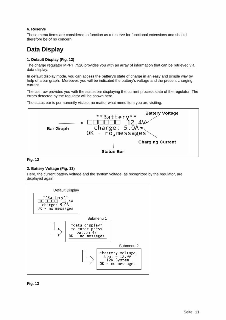
6. ReserveThese menu items are considered to function as a reserve for functional extensions and should therefore be of no concern.
Data Display1. Default Display (Fig. 12)The charge regulator MPPT 7520 provides you with an array of information that can be retrieved via data display.
In default display mode, you can access the battery's state of charge in an easy and simple way by help of a bar graph. Moreover, you will be indicated the battery’s voltage and the present charging current.
The last row provides you with the status bar displaying the current process state of the regulator. The errors detected by the regulator will be shown here.
The status bar is permanently visible, no matter what menu item you are visiting.
Fig. 12
2. Battery Voltage (Fig. 13)Here, the current battery voltage and the system voltage, as recognized by the regulator, are displayed again.
Fig. 13
Default Display
Submenu 1
Submenu 2

Seite 12
3. Charging Current (Fig. 14)Display of the Battery’s Charging Current
Fig. 14
4. Temperature of Battery (Fig. 15)You may retrieve information about the temperature only while the sensor is being connected. If this is not the case, the display shows T=999°C and “sensor broken.” Please consider that the same is displayed in the events of a defect sensor or cable break.
Fig. 15
Default Display
Submenu 1
Submenu 2
Default Display
Submenu 1
Submenu 2

Seite 13
5. Temperature of Cooling Element (Fig. 16)A maximum temperature of the cooling element is important as it prevents the MPPT 7520 from overheating. In order to protect itself fro overheating, the regulator starts gradually reducing the charging current if the temperature exceeds 50°C.
Fig. 16
6. Module Voltage (Fig. 17)The MPPT 7520 displays the current module voltage and helps you detect occurring system errors more quickly.
Fig. 17
Default Display
Submenu 1
Submenu 2
Default Display
Submenu 1
Submenu 2

Seite 14
7. Ampere-Hour Meter (Fig. 18)The MPPT 7520 has an in-built electricity meter, which provides easy access to the battery charging process’ total ampere-hours. After initial operation, a value of 2 Ah or less will be indicated. For after manufacturing, every single apparatus is being checked under load, thus the small value of the electricity meter.
Fig. 18
8. ReserveThe info menu has also reserve items, which are however meant to function as a reserve for functional extensions and should therefore be of no concern.
MessagesThe regulator can issue the following messages:
Malfunction Message Meaning What to do?OK - no messages Default display, if no problems
occurringNo need for action
Panel polarity! Module input with reverse polarity
Change polarity at module input
PV overvoltage! Module voltage too high Off-load voltage of one string must not exceed 75 V
No valid battery Battery voltage beyond approved limits
Replace defect battery
Battery low! Battery deep discharged Pre-charge by AC-adapter until voltage exceeds 10 V
Battery error! General problem with battery Battery possibly defect, please replace it
Temp. warning! Temperature of cooling element exceeds 45°C
No need for action
Power derating! Temperature of cooling element exceeds 50°C, apparatus derates battery rating
Protective function, lowered ambient temperature preferable
Default Display
Submenu 1
Submenu 2

Seite 15
DisclaimerThe manufacturer shall not be liable for damages, especially on the battery, caused by use other than as intended or as mentioned in this manual or if the recommendations of the battery manufacturer are neglected. The manufacturer shall not be liable if there has been service or repair carried out by any unauthorized person, unusual use, wrong installation, or bad system design.
General Safety Recommendations Batteries store a large amount of energy. Never short circuit a battery under all circumstances. We
recommend connecting a fuse (slow acting type, according to the nominal regulator current) directly to the battery terminal to avoid cable fire.
Please observe the safety recommendations of the battery manufacturer. Avoid touching or short circuiting wires or terminals. Be aware that the voltages on specific wires
and terminals can be up to 75 V. Avoid disconnecting the generator’s wires under load. This may cause sparks. Danger – fire
hazard! Keep children away from batteries and the charge regulator. Installation and mounting of the regulator should be carried out by an authorized dealer or
installer and be done according to the applicable regulations of state-of-the-art technology.
If in doubt about installation, consult us. We are happy to support you.Please consider that once an error has been made, it would be hard to correct it. Better to have asked us once too often, than having caused damage. You can contact us as follows:
Hotline +49 (0) 2161 977-2914E-mail [email protected]
SpecificationsElectrical Data Battery Efficiency 97,5% Types of batteries Lead-acid, AGM, gel
Nominal voltage of battery 12 or 24 V MKT-charging process Main charging, trickle charging, maintenance mode
Maximum charging current 20 A
Battery voltage range 7-36 V Temperature compensation
-3mV/°C / cell (20°C temperature)
Max. PV off-load voltage 75 V Temperature range -20°C to +60°C
Typical generator output 12 V 300 W24 V 600 W
Mechanical Data
Digital output 100 mA Measurements LxBxH 180x180x50mm
Consumption of auxiliaries 27 mA Weight 2.1 kg
Connecting terminals 16mm² / 6AWG
Ambient Data Casing Aluminum / steel
Working temperature -20°C to +60°C
Storage temperature -30°C to +70°C Options Humidity 99% non-condensing Ext. temperature sensor
Various power relaysProtective Functions Certifications PV input Short circuit, polarity,
overload CE-conform
Reverse battery protection Module input, battery input
RoHS-conform
Overvoltage PV-generator

Seite 16
Made in GermanySoltronicwww.soltronic.de