solution crystal growth on earth and in space
TRANSCRIPT

1
Growth and Characteristics of Bulk Single Crystals Grown from
Solution on Earth and in Microgravity M. D. Aggarwal+, A. K. Batra, R. B. Lal
Department of Physics, P.O. Box 1268 Alabama A&M University Normal, AL 35762, USA
Benjamin G. Penn and Donald O. Frazier
NASA / Marshall Space Flight Center, Huntsville, AL 35812, USA
ABSTRACT
The growth of crystals has been of interest to physicists and engineers for a long time
because of their unique properties. Single crystals are utilized in such diverse applications as
pharmaceuticals, computers, infrared detectors, frequency measurements, piezoelectric
devices, a variety of high technology devices and sensors. Solution crystal growth is one of
the important techniques to grow a variety of crystals when the material decomposes at the
melting point and a suitable solvent is available to make a saturated solution at a desired
temperature. In this chapter an attempt is made to give some fundamentals of growing
crystals from solution including improved designs of various crystallizers. Since the same
solution crystal growth technique could not be used in microgravity, authors had proposed a
new cooled sting technique to grow crystals in space. Authors’ experiences of conducting two
space shuttle experiments relating to solution crystal growth are also detailed in this work.
The complexity of these solution growth experiments to grow crystals in space are discussed.
These happen to be some of the early experiments performed in space, and various lessons
learnt are described. A brief discussion of protein crystal growth that also shares basic
principles of solution growth technique is given along with some flight hardware information
for its growth in microgravity.
Key Words: Solution crystal growth; Microgravity; Triglycine sulfate; Protein crystals,
Spacelab-3, International Microgravity Laboratory-1 + Present Address: NASA Administrator’s Fellow, EV-43 ISHM and Sensors Branch, NASA /Marshall Space Flight Center, Huntsville, AL 35812, USA
https://ntrs.nasa.gov/search.jsp?R=20110006347 2018-02-07T23:32:48+00:00Z

2
Contents
1.0 INTRODUCTION
2.0 CRYSTALLIZATION: NUCLEATION AND GROWTH KINETICS
2.1 Expression for supersaturation
2.2 Effects of convection in solution growth
2.2.1 Natural convection
2.2.2 Forced convection
2.3 Effect of impurities
3.0 CLASSIFICATION OF CRYSTAL GROWTH
4.0 LOW TEMPERATURE SOLUTION GROWTH
4.1 Solution growth methods
4.1.1 Slow cooling method
4.1.2 Slow evaporation method
4.1.3 Temperature gradient method
4.1.4 Chemical/Gel method
5.0 SOLUTION GROWTH BY TEMPERATURE LOWERING
5.1 Solvent selection and solubility
5.1.1 Solubility determination
5.2 Design of a crystallizer
5.2.1 A Typical solution crystal growth crystallizer
5.2.2 Crystal seed-holder 5.2.3 Preparation of seed crystal and mounting
5.3 Solution preparation and starting a growth run
6.0 TRIGLYCINE SULFATE CRYSTAL GROWTH– A CASE STUDY
6.1 Growth of single crystals of triglycine sulfate
6.2. Growth kinetics and habit modification
6.2.1 Effect of seed crystal
6.2.2 Effect of growth temperature and supersaturation
6.2.3 Effect of pH of the solution
6.2.4 Effect of impurities

3
7.0 SOLUTION GROWTH OF TRIGLYCINE SULFATE CRYSTALS IN
MICROGRAVITY ABOARD SPACELAB-3 AND IML-1
7.1 Rationale for solution crystal growth in space
7.2 Crystal growth method in space
7.2.1 Cooled sting technique
7.2.2 Flight hardware
7.2.3 Flight optical system
7.3 Results and Discussion
8.0 PROTEIN CRYSTAL GROWTH
8.1 Protein crystal growth methods
8.2 Protein crystal growth mechanisms
8.3 Protein crystal growth in microgravity
9.0 CONCLUDING REMARKS
Acknowledgements
References
4
1.0 INTRODUCTION
The growth of crystals with tailored physical and chemical properties,
characterization of crystals with advanced instrumentation and their eventual conversion into
devices, play a vital role in science and technology. Crystal growth is an important field of
materials science, which involves controlled phase transformation. Growth of crystals
from solution at low temperature is one of the important techniques in the field of
science: pharmaceutical, agriculture and materials science. Crystal growth acts as a
bridge between science and technology for practical applications. In the past few decades,
there has been a growing interest in the crystal growth process, particularly in view of the
increasing demand for materials for technological applications. The strong influence of
single crystals in the present day technology is evident from the recent advancements in the
fields of semiconductors, transducers, infrared detectors, ultrasonic amplifiers, ferrites,
magnetic garnets, solid state lasers, nonlinear optic, piezoelectric, acousto-optic,
photosensitive materials and crystalline thin films for microelectronics and computer
applications. All these developments could be only achieved due to the availability of single
crystals such as silicon, germanium, gallium arsenide, and also with the discovery of
nonlinear optical properties in some inorganic, semi-organic and organic crystals. Researchers
have always been in the search of new materials for the growth of single crystals for new
applications and modifying present crystals for various applications. Any crystal growth
process is complex; it depends on many parameters which can interact. A complete
description of a process may well be impossible, since it would require the specifications of
too many variables. That is why, sometimes crystal growth is called art and science but like
other crafts, it can provide great satisfaction after a successful crystal growth of a desired
material.
The solid-state materials can be classified into single crystals,
polycrystalline, and amorphous materials depending upon the arrangement of constituent
molecules, atoms or ions. An ideal crystal is one, in which the surroundings of any atom
would be exactly the same as the surroundings of every similar atom in three dimensions.
Real crystals are finite and contain defects. The consistency of the characteristics of devices
fabricated from a crystal depends on the homogeneity and defect contents of the crystals.
Hence, the process of producing single crystals, which offer homogeneous media in the

5
atomic level with directional properties, attracts more attention than any other process. The
methods of growing crystals are mainly dictated by the characteristics of the material
and the desired size of the crystal. The method of growing crystals at low and high
temperature can be broadly divided into the following six categories: (i) Growth from
aqueous solution (low temperature growth); (ii) Growth by gel method (low temperature
growth); (iii) Growth from flux or top seeded solution growth method (high temperature
growth); (iv) Hydrothermal growth (high temperature growth); (v) High pressure growth
(high temperature growth); and (vi) Growth by electrodeposition
Growth of bulk crystals from aqueous solution is technically very important. Besides
bulk crystal growth, this method is also used for the purification of materials and the
separation of impurities. Growth of large single crystals from aqueous solution is of interest
for essentially two reasons. First, there is a growing need for solution-grown crystals in the
area of high-power laser technology like potassium dihydrogen phosphate (KDP) type
crystals. Second, research on this area of crystal growth and the corresponding in-depth
examination of several key parameters provides fundamental case studies generating theory
and technology, applicable to all of solution crystal growth processes, including new aqueous
growth systems and high temperature solution growth.
In this chapter, the fundamental aspects of solution growth and the different methods of
bulk crystal growth from solution are described along with solution crystal growth in the
microgravity environment of space. Based on extensive experience of the authors in growing
inorganic and organic crystals on earth and in space, the authors have tried to give a lucid
explanation of the fundamentals of solution crystal growth and crystal growth systems. However,
enough details are given on fabrication of crystallizers, associated instruments, and techniques so
that new researcher may be able to design and set up his/her own solution crystal growth system
after review of this chapter. Furthermore, growth and perfection of technologically important
crystal from aqueous solution based on a case study of triglycine sulfate is presented. Effects of
various parameters such as design of the seed holder, seed morphology, characteristics of the
solution such as pH, temperature of growth, dopants, impurities; and microgravity on the physical
properties are presented in detail.

6
2.0 CRYSTALLIZATION: NUCLEATION AND GROWTH KINETICS
The study and investigation of crystal growth implies the determination of growth
laws, growth mechanisms and explanation of final result, i.e. the crystal habit. These aspects
are interconnected. Since the growth rate of a face depends on its growth mechanisms and
contributes to define the crystal habit, the detailed knowledge of these aspects is essential for
the production of crystals of specific physical or morphological properties. The crystal
growth is due to deposition of solute particles on the crystal faces, which can grow layer by
layer at different rates. The growth rate of a face, i.e. advancement of its surface in the
normal direction per unit time, depends upon internal and external factors. Internal factors
are the surface structure of faces, which in turn are related to the bulk crystal structure, and
their degree of perfection. Defects usually occur in the crystals and can emerge at the surface,
affecting the growth kinetics. External factors are supersaturation, solute concentration which
is related to solubility, temperature of the solution, solution composition, mechanical
conditions such as still or stirred solution, presence of impurities, magnetic field, and
gravitational field. The crystal growth of a face is a succession of complex processes, which
take place at the interface between the liquid and solid phase. It therefore implies transport of
matter and energy across the interface, which is the site of major importance in crystal
growth.
In the following section, the fundamentals of nucleation and crystal growth at low
temperature solution are described.
2.1 Expression for supersaturation
The supersaturation of a system can be expressed in a number of ways. A basic unit of
concentration as well as temperature must be specified. The concentration driving force (ΔC),
the supersaturation ratio (S) and relative supersaturation (σ) are related to each other as
follows:
The concentration driving force
ΔC = C - C* (1)
where C is the actual concentration of the solution and C* is the equilibrium concentration at
a given temperature.
Supersaturation ratio

7
S = C / C* (2)
Relative supersaturation,
σ = (C - C*) / C* or σ = S - 1 (3)
If the concentration of a solution can be measured at a given temperature and the corresponding
equilibrium saturation concentration is known, then the supersaturation can be estimated.
The required supersaturation can be achieved either by cooling/evaporation or addition
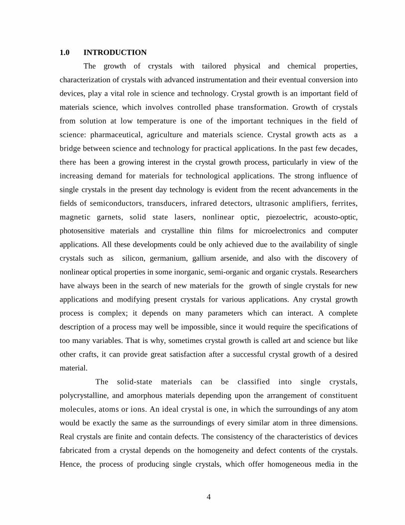
of a precipitant. Meirs and Isaac reported a detailed investigation on the relationship between
supersaturation and spontaneous crystallization [1]. The results of their analysis are shown in
Fig. 1. It shows three zones, which are termed as region I, II and III. The lower continuous
line is the normal solubility of the salt concerned. Temperature and concentration, at which
spontaneous crystallization occurs, are represented by the upper broken curve, generally
referred as the super-solubility curve. This curve is not well defined as the solubility curve
and its position in the diagram depends on the degree of agitation of the solution. The three
zones are defined as follows:
I. The stable (undersaturated) zone, where crystallization is not possible
II. The metastable zone, where spontaneous crystallization is improbable. However,
if a seed crystal is placed in such a metastable solution, growth will occur
III. The unstable or labile (supersaturation) zone, where spontaneous crystallization
is more probable.
The achievement of supersaturation is not sufficient to initiate the crystallization. The
formation of embryos or nuclei with a number of minute solid particles present in the
solution, often termed as centers of crystallization, is a prerequisite. Nucleation may occur
spontaneously or it may be induced artificially. Broadly nucleation can be classified into
primary and secondary. All types of nucleation, homogeneous or heterogeneous in systems,
which do not contain crystalline matter comes under primary. On the other hand, nucleation
generated in the vicinity of crystals present in a supersaturated system is termed as
secondary.
8
Fig. 1 Meirs and Issac solubility curve
The formation of stable nuclei occurs only by the addition of molecule (A1), till a
critical cluster is formed.
An-1 + A1 → An (critical cluster) (4)
Subsequent additions to the critical cluster result in nucleation followed by
growth. The growth units (ions or molecules) in a solution can interact with one
another resulting in a short-lived cluster. Short chains may be formed initially or flat
monolayers and eventually the lattice structure is built up. This process occurs very rapidly
and continues in regions of very high supersaturation. Many nuclei fail to achieve
maturity and simply dissolve due to their unstable nature. If the nuclei grow beyond a
certain critical size, they become unstable under the average conditions of supersaturation in
the bulk of the solution. The formation of a solid particle within a homogeneous solution
results from the expenditure of a certain quantity of energy.
The total quantity of work `W' required for the formation of a stable nucleus is equal
to the sum of the work required to form the surface WS (a positive quantity) and the work
required to form the bulk of the particle Wv (a negative quantity).

9
W = Ws + Wv (5)
The change in Gibbs free energy (ΔG) between the crystalline phase and the
surrounding mother liquor results in a driving force, which stimulates
crystallization. This ΔG is the sum of surface free energy and volume free
energy.
ΔG = ΔGs + ΔGv, (6)
For a spherical nucleus ΔG = 4π r2γ + 4/3 π r2ΔGv (7)
where r is the radius of nucleus, γ is the interfacial tension and ΔGv is the free energy
change per unit volume.
For rapid crystallization, ΔG < 0; the first term in the above equation expresses
the formation of new surface and the second term expresses the difference in
chemical potential between the crystalline phase (µ) and the surrounding mother liquor
(µo). At the critical condition, the free energy formation obeys the condition dΔG/dr =
0. Hence the radius of the critical nucleus is expressed as
r* = 2 γ/ ΔGv (8)
The critical free energy barrier
ΔG* = (16 π γ3 v2)/3(Δμ)2 (9)
The number of molecules in the critical nucleus is given as
I* =4/3 π γ (r*)3 (10)
The crucial parameter between a growing crystal and the surrounding mother liquor is the
interfacial tension (γ). This complex parameter can be determined by conducting the nucleation
experiments.
Growth of crystals from the vapor, melt or solution occurs only when the medium is
supersaturated. The process involves at least two stages [2]:
(1) formation of stable three-dimensional (3D) nuclei and
(2) development of the stable 3D nuclei into crystals with well-developed faces.
The formation of 3D nuclei is usually discussed in terms of reduction in the Gibbs free
energy of the system. At a given supersaturation and temperature, there is a critical value of the
free energy at which 3D nuclei of a critical radius are formed. Only those nuclei which are
greater than the critically-sized nucleus are capable of growing into crystals of visible size by
the attachment of growth species (i.e. molecules, atoms or ions) at energetically favorable

10
growth sites like kinks (K) in the ledges (L) of a surface. The surfaces of growing crystals may
be flat (F), stepped (S) or kinked (K). However, crystals of visible size are usually bounded
by the slowly-growing F faces which grow by the attachment of growth units at energetically
favorable sites. Fig. 2 shows different positions for the attachment of growth units at a flat
crystal-medium interface of a simple cubic lattice. A growth unit attached at the surface
terrace (T) , a smooth ledge (L) and a kink site (K) has 1, 2 and 3 out of the 6 nearest
neighbors, respectively. Therefore, a growth unit arriving on the surface terrace, at the terrace
ledge and at the kink simply loses one, two and three degrees of freedom. If φ is the binding
energy per pair, the corresponding binding energy of a growth unit attached at these sites is φ,
2 φ and 3 φ, respectively. Since the probability of capture of a growth unit at a given site depends
through terms exp(n φ /kT) (where n is the number of bonds formed, k is the Boltzmann
constant and T is the temperature in Kelvin), the growth unit has a much higher probability
Fig. 2. Different positions for the attachment of growth units at a flat
crystal-medium interface of a simple cubic lattice.
of becoming a part of the crystal at the kink site rather than at the ledge or at the surface
terrace. Consequently, in contrast to ledges, the contribution of kinks is overwhelmingly high in
the rate v of displacement of a step along the surface and in the rate R of displacement of the

11
surface normal to it. Similarly, the contribution to the face growth rate R by the direct
attachment of growth units at the terrace is negligible.
From the above discussion, it may be concluded that the kinetics of crystal growth may, in
general, be considered to occur in the following stages:
(1) Transport of growth units to the growing surface by bulk diffusion and their capture onto
the surface terrace.
(2) Migration of growth units adsorbed onto the terrace to the step by surface diffusion and
their capture at the step.
(3) Migration of growth units adsorbed onto the step to the kink site and their integration
into the kink.
(4) Transport of the released heat of the reaction and solvent molecules from the solvated
atoms/molecules.
One or more of the above stages may control the growth rate but the slowest one is
always rate limiting. However, it should be noted that growth kinetics, characterized by rates
v and R, depends on crystal structure, structure of crystal-medium interface (i.e. rough or
smooth), presence of dislocations emerging on the growing face, supersaturation of the growth
medium, growth temperature, stirring and impurities present in the growth medium. It is also
these factors which ultimately determine the surface morphology of crystals.
To explain the crystal growth processes, various theories and models and role of
impurities , have been proposed in the past. Some of them are listed below. For details, one
can refer to various excellent references and references therein [2-36]. The important growth
models are: (i) Two-dimensional nucleation models;(ii) Spiral growth models; (iii)
Bulk diffusion models ; and (iv) Growth by a group of cooperating screw
dislocations.
2.2 Effects of Convection in Solution Growth
Convection is comprised of two mechanisms: energy transfer due to random
molecular motion (diffusion), and energy transferred by the bulk or macroscopic, motion of
the fluid. This fluid motion is associated with the fact that, at any instance, large numbers of
molecules are moving collectively or as aggregates. Such motion, in the presence of a
temperature gradient, contributes to heat transfer. Because the molecules in the aggregate
12
retain their random motion, the total heat transfer is then due to a superposition of energy
transport by the random motion of the molecules and by the bulk motion of the fluid. It is
customary to use the term convection when referring to this cumulative transport and the
term advection referring to transport due to bulk fluid motion.
2.2.1 Natural Convection
Convection heat flow can be classified as natural (or free) convection and forced
convection according to the nature of the fluid flow. Natural convection is due to density
difference of a solution near a crystal and far from it. Density difference is due primarily to
concentration change of a solution during growth or the dissolution of a crystal; and,
secondly, due to the absorption or evolution of the heat in the fluid. In natural convection,
fluid motion is due to buoyancy forces within the fluid. Buoyancy is due to the combined
presence of a fluid density gradient and a body force that is proportional to density. In
practice, the body force is usually the gravitational force. Free convection flows may occur in
the form of a plume. The well-known convective flow pattern for solution growth is
associated with fluid rising from the bottom of the crystal. During the growth of a crystal,
solution rises because the solution near a crystal is less dense as a result of the reduction in
the concentration, and the temperature is higher because of the evolution of the heat of
crystallization. With this depletion of the heavier solute, the solution around the crystal
becomes lighter and, thus, rises. When the crystal is dissolved, the direction of the motion is
opposite (downward). Under these conditions, the diffusion of molecules is supplemented by
the more energetic convective transport of matter.
Diffusion is the distribution of a substance by a random motion of individual particles.
It is due to the presence of a gradient of the chemical potential in the system. A gradient is
defined as an incremental of a function in an infinitely short distance, along the direction of
the most rapid variation of the function. Diffusion always reduces this gradient. Molecular
diffusion is observed in viscous media and at low supersaturations, as well as in the growth
of crystals, in thin films of liquids or in capillaries. In molecular diffusion the transport of
matter to a crystal is slower than under other diffusion conditions. The thickness of the
boundary layer increases with time and the concentration gradient gradually decreases.
Therefore, the rate of growth decreases with time. The time interval during the formation of a
boundary diffusion layer represents the non-steady state condition. During this initial period,

13
the rate of growth varies considerably. The thickness of the boundary layer depends on the
difference between the densities of different parts of the solution (i.e., on the rate of growth
of a crystal), the viscosity of the solution, and the dimensions of the crystal. The presence of
the boundary near the crystal and the orientation of the crystal itself affects the nature of the
convection currents and the thickness of the boundary layer at different crystal faces.
2.2.2 Forced Convection
Forced convection is produced by the action of external forces such as the forced
motion of a crystal in solution. There is no basic difference between forced and natural
convection. When the velocity of motion of a solution with respect to a crystal is increased,
the thickness of the boundary layer increases and the supply of matter to a face of the crystal
increases. Therefore, by increasing the rate of motion of a solution, we can increase the
growth rate of the crystal faces. However, we cannot continue this processing indefinitely. A
temperature gradient constitutes the driving potential for heat transfer. Similarly,
concentration gradient of a species in a mixture (or solution) provides the driving potential of
mass transfer. Both conduction heat transfer and mass diffusion are transport processes that
originate from molecular activities. Crystal growers are actually concerned with two aspects
of the nutrient-to-crystal transport:
(a) With the mass flux across an interface, which we will call the interfacial flux and
which determines the crystal growth rate; and
(b) With the concentration profile of growth species in the nutrient adjacent to the
crystal, which is an essential parameter in morphological stability discussions.
Let us now introduce the dimensionless numbers that govern forced convection
and free convection. The Grashof number Gr
Gr = 2
3
vLTg ∆β (11)
where g is gravitational acceleration (m/s2), (β is thermal expansion coefficient
(β = 1/ρ(δρ/δT) where ρ is density, ΔT is the temperature difference between the horizontal
surfaces that are separated by L, and v is kinematic viscosity (m2/s). The Grashof number G,
plays the same role in free convection that the Reynolds number plays in forced convection.
The Reynolds number Re,
Re = VL/v = ρVL/μ (12)

14
where V is velocity (m/s), L is characteristic length (m), v is kinematic viscosity (m2/s), ρ is
density, and μ is viscosity (kg/s.m). The Reynolds number Re provides a measure of the ratio
of the inertial to viscous forces acting on a fluid element. In contrast, the Grashof number Gr,
indicates the ratio of the buoyancy force to the viscous force acting on the fluid.
2.3 Effect of Impurities
We will now define impurities which are inherently present, and additives or
dopants which are deliberately added. The former are naturally present in the growth
environment and are unwanted; the latter are deliberately added in order to control
nucleation, improve crystal quality, increase the size, change the crystal habit and other
physical properties. This topic has received great attention since it is of relevant theoretical
and practical interest in the growth of crystals of industrial importance. The ability of
impurities to change the growth behavior has been studied by many authors [23-36]. It is
well known that the influence of impurities on the crystal form and the growth rate is based
on the adsorption of the foreign species ions, atoms or molecules at kinks, ledges and
terraces of a growing crystal. The change of the crystal form is based on a difference in
adsorption energies on different faces. Impurity molecule will be adsorbed preferentially on
surfaces where the free adsorption energy has the maximum. It has been possible to predict
the preferred surface using computational approaches [37]. Recently the mechanisms and
models of adsorption of impurities during the growth of bulk crystals have been surveyed
by Sangwal including kinetic effects of impurities on the growth of single crystals from
solution [36].
Solvent itself is an impurity. High temperatures and high supersaturations increase
growth rate, but in the presence of a solvent the effect of temperature is stronger, since it
promotes water desorption and growth kinetics much more than supersaturation, as found for
sucrose [38-39]. Anomalies found by Chernov et al., [40] at 10° and 40°C in growth rates
disappeared when ethanol, which is known to disrupt the bulk structure of water, was
added to the solution. Indeed, water adsorbed on crystal surfaces has properties differing
from those of free water. This is attributed to the different structures of the adsorbed layer
which undergo phase-like trasformations at the above temperatures.
Impurity adsorption can be indirectly studied though the adsorption isotherm, i.e. the
fraction θ of adsorbed sites which are occupied as the impurity concentrations Ci

15
increase. The simplest model of localized adsorption, i.e. situated at lattice sites, is the
Langmuir isotherm:
Ka Ci = θ / (1 + θ), (13)
Where Ka is the temperature-dependent adsorption constant, which is different for each
crystal face. Other models have been proposed, which take into account the interactions
between adsorbed impurities or the occupation probability.
Impurities can act in different ways. When they interact with solute or solvent, they can
have strong influences on solubility and consequently on supersaturation and kinetic
processes. When impurities are adsorbed on crystals, they can have thermodynamic and
kinetic effects. The dominant effect is the exchange rates in which the adsorbed molecule or
ions and growth units are involved. If the former are exchanged more rapidly than the
latter, adsorption mainly affects surface and edge free energy. For a face a decrease of γi
(interfacial energy of face i) results, according to the Gibb's equation
Δγi = kT In(1- θ)/S (14)
where S is the area of the adsorption site. Similarly, the edge free energy is decreased.
These effects should cause an increase in the nucleation and growth rate. If the exchange
rate of the adsorbed molecules is slower, impurities can strongly decrease the kinetic
coefficients (RF=Kσ2 at low supersaturation: RF=K’σ at high supersaturation, where K
and K’ being kinetic coefficients the value of which depend on temperature and growth
mechanisms, RF is growth rate of F face and σ is the relative supersaturation). So that as
a final result the kinetic effects dominate the thermodynamic ones and a decrease in
growth rate and impingement flux occur. The interpretation of impurity effects can be
done on a structural and kinetic basis:
a) Low concentrations of impurity can form an adsorbed monolayer on the surface
even in undersaturated solutions, due to structural relationship between the 2D structure of
crystal face and the adsorbed layer (as in the case of NaCl grown in the presence of CdCl2: a
monolayer of Na2CdCl2.3H2O is formed). The main influence is on the crystal habit.
b) Kinetic interpretation considers the possibility of adsorption on the different surface
sites If impurities are adsorbed in the kinks, the advancement rate of the edge is hindered
even at very low impurity concentrations and growth rate is strongly decreased even
blocked. Adsorption can also occur on the surface with so strong bonds that impurity

16
molecules cannot move and form a barrier through which the steps have to filter. The
spreading of steps beyond this barrier demands supersaturation higher than a critical value for
each impurity concentration. In this case impurities are incorporated. The tailor-made
additives are used to modify the crystal habit for industrial needs. The molecules of these
impurities are similar to those of crystals, but contain some structural differences, so that when
they are incorporated into the crystal they disrupt some bonds and change the growth
rate of the faces.
3 . 0 CLASSIFICATION OF CRYSTAL GROWTH
The methods of growing single crystals may be classified according to their
phase transformation as given below:
Growth from solid → solid-solid phase transformation
Growth from liquid → liquid-solid phase transformation
Growth from vapor → vapor-solid phase transformation
One can consider the conversion of the polycrystalline piece of a material into a single
crystal by imagining that the grain boundaries are swept through and pushed out of the
crystal in the solid-solid growth of crystals. The crystal growth from liquid falls into four
categories namely: (i) Melt growth; (ii) Flux growth; (iii) Hydrothermal growth ; and (iv)
Low temperature solution growth.
There are number of growth methods in each category. Among the various methods of
growing single crystals [41-43], solution growth at low temperature occupies a prominent
place owing to its versatility and simplicity. Growth from solution occurs close to
equilibrium conditions and hence crystals of high perfection can be grown.
4.0 LOW TEMPERATURE SOLUTION GROWTH
Solution growth is the most widely used method for the growth of crystals, when the
starting materials are unstable or decompose at high temperatures. This method demands
that the materials must crystallize from solution with prismatic morphology. In general,
this method involves seeded growth from a saturated solution. The driving force i.e. the
supersaturation is achieved either by temperature lowering or by solvent evaporation.
This method is widely used to grow bulk crystals, which have high solubility and
have variation in solubility with temperature. After many modifications and

17
refinements, the process of solution growth now yields good quality crystals for a
variety of applications. Growth of crystals from solution at room temperature has many
advantages over other growth methods though the rate of crystallization is slow. Since
growth is carried out close to room temperature, the structural imperfections in solution
grown crystals are relatively low.
4.1 Solution growth methods
Low temperature solution growth can be subdivided into the following
categories; (i) slow cooling method; (ii) slow evaporation method; (iii) temperature gradient
method ; and (v) Chemical / Gel method
4.1.1 Slow cooling method
Slow cooling is the best way to grow crystals by solution technique. The main
disadvantage of slow cooling method is the need to use a narrow range of temperature. The
possible range of temperature is usually narrow and hence much of the solute remains in
the solution at the end of the growth run. To compensate this effect, large volume of
solution is required. Wide range of temperature may not be desirable because the properties of
the grown crystal may vary with temperature. Even though this method has technical
difficulty of requiring a programmable temperature control, it is widely used with great
success. In this method, growth occurs without any secondary nucleation in the solution, if
the supersaturation is fixed within the metastable zone limit. A large cooling rate changes
the solubility beyond the metastable zone width and multinucleation occurs at the
expense of the seed crystal. A balance between the temperature lowering and the growth
rate has to be maintained. Growth at a low supersaturation prevents strain and dislocation
formation at the interface. Supersaturation can be increased after initial growth to arrive
at a reasonable growth rate.
4.1.2 Slow evaporation method
This method is similar to the slow cooling method in terms of the apparatus
requirements. The temperature is fixed and provision is made for evaporation. With non-
toxic solvents like water, it is permissible to allow evaporation into the atmosphere.
Typical growth conditions involve a temperature stabilization of about ± 0.05°C and
rates of evaporation of a few mm3/h. The evaporation technique has an advantage that
the crystals grow at a fixed temperature. But inadequacies of the temperature control

18
system still have a major effect on the growth rate. This method can effectively be
used for materials having very low temperature coefficient of solubility.
4.1.3 Temperature gradient method
This method involves the transport of materials from a hot region
containing the solute material to be grown to a cooler region, where the solution is
supersaturated and the crystal grows. The main advantages of this method are that
( i ) crystal grows at fixed temperature,
(ii) insensitivity to changes in temperature provided both the
source and growing crystal undergo the same change and
(iii) economy of solvent and solute.
On the other hand, a small temperature difference between the source and
the crystal zones has a large effect on the growth rate.
4.1.4 Chemical / Gel method
The gel method is exceedingly simple. One procedure is to prepare gel using
commercial waterglass, adjusted to a specific gravity of 1.06g/cm3. Gel is then mixed with
1M tartaric acid and allowed to gel in a test tube. Once gel is formed some other solution
can be placed on the top ( 1M CaCl2 solution) as shown in Fig. 3 .In due course of time,
crystals of calcium tartrate tetrahydrate are formed in the gel. In the nutshell, one solution
diffuses through the gel and reacts with other solution to form crystals of appropriate
chemicals [44].
Fig. 3. Schematic diagram of the gel crystal growth process
19
5.0 SOLUTION GROWTH BY TEMPERATURE LOWERING
The growth of crystals from solution from low temperature solutions occupies a
prominent place especially when materials are not stable at elevated temperatures. A number
of concepts for solution crystal growth systems are found in literature. One of the best
concepts for growth of both inorganic and organic crystals from solution is by temperature
lowering of a solution provided the material has positive temperature coefficient of solubility.
In this method, a saturated solution of the material to be grown, is prepared at a chosen
temperature and kept at this temperature for 24 hours. Then the seed holding rod is inserted
in the growth chamber and its rotation is initiated. The growth process is initiated by
lowering the temperature slowly. The temperature of the solution is lowered at a pre-
programmed rate typically 0.05°C to 2.0°C per day depending on the solubility of the chosen
material. The complete crystallization process may take from a week to several weeks. To
terminate the growth process the grown crystals are taken out of the solution without thermal
shock.
A solution crystal growth is a highly complex process and depends on various
growth parameters such as quality of seed, temperature of growth, temperature lowering rate,
character of solution, seed rotation and stirring of solution besides other conditions. To grow
good quality crystals, the above cited parameters have to be optimized for each crystal.
5.1 Solvent selection and solubility
A solution is a homogeneous mixture of a solute in a solvent. The solute is
the component present in a smaller quantity. For a given solute, there may be different
solvents. Apart from high purity starting materials, solution growth requires a good
solvent. The solvent must be chosen by taking into account the
following factors :
(i) high solubility for the given solute,
(ii) good solubility gradient,
(iii) low viscosity,
(iv) low volatility and
(v) low corrosion.
If the solubility is too high, it is difficult to grow bulk single crystals and if too
small, solubility restricts the size and growth rate of the crystals. Solubility data at various

20
temperatures is essential to determine the level of supersaturation. Hence, the solubility of the
solute in the chosen solvent must be determined before starting the growth process. If the
solubility gradient is very small, slow evaporation of the solvent is the other option for crystal
growth to maintain supersaturation in the solution. Growth of crystal from solution is mainly a
diffusion-controlled process; the medium must be less viscous to enable faster
transference of the growth units from the bulk solution to the growth site by
diffusion. Hence a solvent with less viscosity is preferable. Most important single crystals such
as potassium dihydrogen phosphate (KH2PO4) and (L)-arginine phosphate monohydrate (LAP)
are grown in aqueous solutions or in solvents that are mixtures of water and miscible organic
solvents. Of all known substances, water was the first to be considered for use as a solvent
because it is nontoxic, most abundant, and low cost. A proper choice of solvent based on a
knowledge of its chemical reactivity helps one to avoid undesired reactions between solute and
solvent. Except that, in general, the solubility of the growth materials in solvents is required to
be sufficiently large, the solubility parameter δ can often be used in estimating the solubility of
nonelectrolytes in organic solvents :
δ = (ΔU/Vm)1/2= (ΔH - RT/Vm)
1/2 (15)
where Vm is the molar volume of the solvent, ΔU is the molar energy, and ΔH is the molar
enthalpy. δ is a solvent property that measures the work necessary to separate the solvent
molecules. Often a mixture of two solvents, one having a δ -value higher than that of a
solute and the other lower, is a better solvent than either of the two solvents separately [45].
A selection of δ-values is given in Table 1 .
Another property, that is, the dipole moments between the solute and solvent, may also be
considered for selecting solvent for crystal growth. Most typical organic solvents have a dipole
moment less than about 3 debye Therefore, in the case of a solute having a similar value of
dipole moment, a much wider choice of solvents is possible.
5.1.1 Solubility determination
Solubility is an important parameter for crystal growth from solution at low
temperature. Before any solution growth technique can be applied, determination of
congruent or incongruent solubility and the establishment of absence of compound
formation with pure or mixed solvents must be achieved. In the latter cases, a special
compositional and thermal regime will be necessary to crystallize the desired phase. A

21
simple apparatus for solubility studies is shown in Fig. 4. Visual inspection allows the
determination of the solubility. Upon cooling crystallized material is obtained for solid
phase analysis . This apparatus is easily fabricated and is very convenient for measuring
solubility. The following is a description of how this has been achieved. The solute and
solvent were weighed into a glass ampoule. The ampoule was seated and rotated in a bath
controlled by a thermostat, the temperature of which was increased in steps of 0.5°C every
1-2 h. The final disappearance of the solute yields the saturation temperature. The
accuracy of this measurement was within ±0.5°C.
However, the time needed to reach equilibrium for most covalent organic materials is
usually shorter than that of sparingly soluble salts, but the settling times before analyses
may be longer. In many soluble salts, such as potassium dihydrogen phosphate, KH2PO4
(KDP), triglycine sulfate (NH2CH2COOH)3H2SO4 (TGS), and (CH2NH2)2C2H4O6 (EDT),
the solubility is strongly temperature dependent. On the other hand, for some soluble salts,
such as LiIO3 and Li2SO4.H2O, the solubility is not dependent on temperature and even has
inverse slope.
Various techniques for measuring solubility such as methods based on the the vortex
flow caused by concentration and optical effects can be found in the literature. However, an
accurate measurement of supersaturation is usually difficult. Some new methods such
Fig. 4 Apparatus for solubility studies as well as equilibration of feed material and growth
solution.

22
Table I. Solubility Parameters δ of Water and Some Organic Solvents at 25°C
Solvent δ (MPa1/2) Solvent δ (MPa1/2)
Water 47.9 Acetic acid 20.7
Methanol 29.6 1,4-Dioxane 20.5
Ethanol 26.0 Carbon disulfide 20.4
Formamide 39.3 Cyclohexanone 20.3
N-Methylformamide 32.9 Acetone 20.2
1,2-Ethanediol 29.9 1,2-Dichloroethane
20.0
Tetrahydrothiophene-l,1- dioxide
27.4 Chlorobenzene 19.4
N,N-Dimethylformamide 24.8 Chloroform 19.0
Dimethyl sulfoxide 24.5 Benzene 18.8
Acetonitrile 24.3 Ethyl acetate 18.6
1-Butanol 23.3 Tetrahydrofuran 18.6
Cyclohexanol 23.3 Tetrachloromethane
17.6
Pyridine 21.9 Cyclohexane 16.8
t-Butanol 21.7 n-Hexane 14.9
Aniline 21.1 Perfluoro-n-heptane
11.9

23
as holographic phase-contrast interferometric microphotography and trace fluorescent probe
have been developed . Using these techniques, the concentration distributions and thickness
of the boundary layers under different convection conditions could be measured with greater
accuracy. Although these methods still need more development and refinement to
become more generally applicable, they are promising alternatives for determination of
supersaturation of easily soluble compounds. Of course, if the solubility is known,
supersaturation can be calculated by measuring the temperature of the solution and its
equilibrium temperature. The problem is that equilibrium temperature measurements are not
always easy.
5.2 Design of a Crystallizer
When designing crystallizer for growing crystals from solution by the temperature
lowering method, the following conditions should be met [43, 46-47]:
(i) The range of operating temperature from room temperature to 80ºC, depending on the
solvent.
(ii) The choice of hydrodynamic conditions in the solution.
(iii) Measurements of growth parameters such a growth rate.
(iv) The arrangement of the taking out the grown crystals from the crystallizer without
any thermal shock.
(v) The arrangement of changing the saturation/temperature decrease rate.
(vi) The possibility of changing the different kind of seed holders.
(vii) The long term operating reliability of the system.
Since these types of solution crystallizers are not available in the market, one has to design
and fabricate ones’ own system based on ones requirements. A description of a modified
crystallizer for growing large crystals from solutions along with the design of a versatile
electronic reciprocating control system to change and reciprocate the motor speed containing
the seed holding rod for solution growth crystallizer is given below.
In this system, the rotation rate and number of revolutions in the clockwise and
counter clockwise direction can be adjusted as desired. This electronic system alleviates the
problem of jerky motion the of seed holder [56] during reciprocation as in earlier electro-
mechanical systems designed by the authors. Good quality crystals of important nonlinear
optical materials such as Methyl-(2,4-dintropheny)-aminopropanoate: 2-Methyl-4-
24
nitroaniline (MNA:MAP), L-Arginine Phosphate (LAP) L-Histidine tetrafluoroborate
(LHFB), L-Arginine tetrafluoroborate (LAFB) and others such as triglycine sulfate,
potassium dihydrogen sulfate have been successfully grown in authors’ laboratory using this
system [47-53]. The complete crystallization apparatus along with electronic circuit can be
easily fabricated in the laboratory with readily available components.
5.2.1 A Typical Solution Crystal Growth Crystallizer
A schematic diagram of a modified solution crystal growth systems that the authors
designed and fabricated after designing a number of crystallizers [55-58] in our laboratory is
shown in Fig.5. It consists of a 250 ml crystallizer jar (4), which holds the growth solution,
that is placed inside a 2.5 liter glass jacketed kettle (2). The linear and reciprocating motion
of the Teflon seed holder (5) is controlled by a rack-pinion arrangement (8) and electronic
circuit (7) respectively. A reversible motor (6) is used for rotating the seed holder. The
temperature of the growth solution is controlled and programmed by circulating water using
a NesLab bath (1). To prevent evaporation of the solvent, a specially designed oil Teflon seal
(3) and/or RTV/Teflon seal (3) are used. The main advantages of our crystal growth system
are: (i) better temperature stability even with sudden fluctuations in room temperature, (ii)
better control over evaporation of organic solvents, (iii) a mechanical screw type
arrangement for pulling the seed crystal at a controlled rate, (iv) the possibility of varying the
seed orientation and type, and (v) a versatile electronic reciprocating control system to
change and reciprocate the motor speed containing the seed holding rod. Better temperature
stability was accomplished by loading the growth solution in a beaker kept inside the
jacketed vessel.
An air gap provides extra insulation. Moreover, spontaneous nucleation at the bottom of the
growth vessel, which hampers the growth and the crystal yield, is completely eliminated. By
providing an extra lid on the inside beaker and a Teflon seal over the jacketed vessel, the
evaporation of the solvent was reduced dramatically. The inner beaker is filled halfway with
solution rather than three-fourth as usually done and the growing crystal is pulled in a
controlled fashion. Since filling of the inner beaker, to three-forth, is not required, not only
the crystal is annealed in situ but also spurious aloevera-tree like growth near the seed in
some crystals such as MNA:MAP, is greatly reduced or completely eliminated.

25
Fig. 5. Schematic diagram of a new type of crystallizer for growing organic crystals.
(1) Circulating bath; (2) Jacked reaction kettle; (3) RTV/Teflon seal; (4) Crystallizer jar;
(5) Teflon seed holder; (6) Reversible motor; (7) Circuit for reciprocating and controlling
the stirring rate of seed holder; (8) Arrangement for pulling the crystal during growth; (9)
Teflon tape cover; (10) Solution; (11) Seed crystal; (12) Teflon seal; (13) Glass lid.
26
Fig. 6 (a) shows the seed crystal along with a MNA:MAP crystal grown using usual
technique i.e. without pulling the growing crystal. Fig. 6(b) shows the same crystal grown
with pulling where aloevera-tree type growth is avoided. Furthermore, large crystals can
be grown from a smaller amount of expensive mother liquor when the crystal is pulled
while growing.
Another modified solution growth crystallizer was also designed in our laboratory,
whose three dimensional cutout view with reciprocating seed arrangement and other
components is illustrated in Fig. 7. It uses magnetic stirrer to keep the temperature of the
water bath uniform at a particular temperature. A layer of silicon oil on the surface of
water was found to reduce the evaporation of water to a minimum which is a big
improvement over earlier designs.
Besides temperature control, the uniform rotation of seeds is required so that
stagnant regions or re-circulating flows are not produced, otherwise inclusions in the
crystals will be formed. To study and achieve uniform and optimum transport of solute
to the growing crystals, various seed rotation mechanisms have been used in the past. The
unidirectional rotation of the seed leads to the formation of cavities in central regions of a
crystal face because of lesser solute transport to this region than edges and corner of the
growing crystal. Furthermore, non-uniform solute supply favors the formation of
(a) (b)

27
Fig. 6 The Photographs of MNA:MAP seed and (a) aloevera-tree type growth (b),
without aloevera-tree type growth
Fig. 7 A Modified crystallizer with arrangement to stop water evaporation
thick layers which subsequently lead to the trapping of inclusions and the generation of
dislocations. Periodic rotation of the growing crystal in opposite directions suppresses
edge formation but does not eliminate the formation of the central cavity. To avoid these
defects and stagnant regions in the solution, eccentric or clock-wise and counter
clockwise motion of the seed holder is used in growing crystals from solutions. A few
mechanisms [54-56] have been used in the past to generate reciprocating motion of the
seed holder such as electro–mechanical [55] and rack-pinion [56]. In the electro-
mechanical system, a connection of the motor polarity is reversed mechanically by using

28
a micro-switch. In this mechanical system, there is a jerky motion on reversal, which
sometimes causes seeds to fall down. The jerky motion also creates a turbulent flow in
the fluid and hence non-uniform transfer of solute to the growing faces, thereby defective
crystals may be formed. The micro-switch has to be changed frequently due to
mechanical failure. Furthermore, the effect of seed rotation rates on the growth rate and
the quality of the crystals can not be systematically studied because rotation rate cannot
be varied. In the rack-pinion arrangement, there is no jerking motion but one has to
change gears to change rotation and reversal rate, which is quite an involved process.
To improve on these drawbacks, in our Crystal Growth Laboratory at Alabama
A&M University, a versatile solid state electronic circuit for reciprocating the direction
of the seed holder was designed along with added features in such a way as to vary
rotation rate, stopping time on reversal, and controlled timing for clockwise and counter
clockwise motion of the crystal/seed holder [57]. These designed features will allow the
crystal growers to study more decisively the effect of seed rotation rates on the growth
and quality of the grown crystals, thereby optimizing this important parameter for
growing better quality crystals.
A schematic diagram of the basic electronic circuit for reciprocating motion control is
shown in Fig.8. In Fig.8, the timer (Chip LM 555, U3) produces a square wave timing
pulse. It may be set for a particular frequency (POT1) and duty cycle (POT2) in
combination with timing capacitor (C3), and reset if necessary by switch (S2). The
timing wave form is divided by the J-K flip flop chip 74LS112 (U1) to one half the timer
frequency. Parasitic oscillations are suppressed by capacitors (C1, C2 and C4). The two
wave forms are combined by NAND gates chip SN7400 ( U2) to alternately turn on the
transistor (Q1 and Q2) to control the solid state relays (1 and 2) which connect the
alternate sides of the motor capacitor to the 110 VAC return line. Similarly, the
transistor (Q3 and Q4) alternately turn on the indicator lamps (LED1 and LED2).
Current limiting and bias is provided by resistors (R1 through R8). Motor rotation speed
is controlled by potentiometer (POT3). A power supply consisting of the step down
transformer (T1), voltage regulator (U4) and associated filtering circuit (D1 and D2, C5
and C5), and voltage setting divider (R9 and R10) provides 5 VDC to the circuit. The

29
operation of the circuit causes the following sequence of states in the system: during first
interval, the seed holder motor runs counter clockwise; during the second interval,
Fig. 8 The Electronic circuit diagram for reciprocating motion of seed holder for solution
crystallizer
the motor comes to a stop; during third interval, the motor runs clock wise; and during
the fourth interval, the motor again comes to stop. Then the entire cycle of operation in
repeated, and the intervals can be varied as needed for a particular crystal growth
experiment.

30
5.2.2 Crystal Seed-Holder In order to insure the best growth conditions, it is necessary to use a special crystal holder
because the success of an experiment may depend upon its suitability. The selection of the
crystal holder and the method for attaching a seed to it are no less important than the
selection of the growth method. A crystal holder should insure that a seed is held securely in
a desired orientation and that the seed and therefore the growing crystal can be moved in any
required manner. Also, the crystal holder should not become deformed at the selected speed
and direction of the motion or by the weight of the final crystal grown on it. The crystal
holder material should be chemically inert in the solution of the substance being crystallized.
The schematic diagram of two plexiglas seed holders were specially designed,
fabricated, and successfully used by the authors for aqueous solution crystal growth are
shown in Fig. 9.
5.2.3 Preparation of seed crystal and mounting A seed is small fragment of a crystal or a whole crystal which is used to start the
Fig. 9 Plexiglas seed holders for solution growth crystallizers
growth of a larger crystal in a solution. This seed must meet the following requirements:
(i) It should be a single crystal free of cracks or boundaries,
(ii) It should be free of inclusions

31
(iii) Its surface should be free of any sharp cleaved edges
(iv) It must be grown under the same conditions as those to be used in
growing the desired single crystals. Following the above requirements in preparing the
seed crystals will result in the growth of high quality crystals, if other criteria such as
solution preparation etc., are performed carefully as well. Prior to crystal growth, seed
crystals are mounted on plexiglas rods using 100% silicon rubber Dow Corning Silastic
732 RTV adhesive.
5.3 Solution Preparation and Starting a Growth Run
For solution preparation it is essential to have the solubility data of the
growth material at different temperatures. Sintered glass filters of different pore sizes are
used for solution filtration. The clear solution, saturated at the desired temperature is
poured into the growth vessel. For growth by slow cooling, the vessel is sealed to prevent
solvent evaporation. Before starting the crystal growth process, a small crystal suspended in
the solution is used to test the saturation. By varying the temperature, a situation is
obtained where neither growth nor dissolution occurs. The test seed is replaced
with a good quality seed. All unwanted nuclei and the surface damage on the seed
are removed by dissolving at a temperature above the saturation point. Growth is
initiated after lowering the temperature to the equilibrium saturation. A controlled solvent
evaporation can also be used in initiating the growth. The quality of the grown crystal
depends on the a) nature of the seed, b) cooling rate employed and c) agitation of the
solution.
Various new nonlinear optical crystals which holds promise for their use in
optical processing devices such as L-arginine phosphate, L-Histidine tetrafluoroborate, L-
arginine tetrafluoro borate, Methyl-(2,4-dintropheny)-aminopropanoate: 2-Methyl-4-
nitroaniline (MNA:MAP) and L-pyroglutamic acid have been successfully grown using
the above mentioned reciprocating system in combination with temperature lowering
technique described by the authors [47-50]. Some of these crystals are shown in Fig. 10.
In the investigators’ observation and experience, there is significant improvement in the
quality of grown crystals and success rates of the growth runs, which is evident from the
transparency and less scattering that is observed using laser illumination. This reciprocal
32
motion control electronic system for the solution growth crystallizers has been in use in
our laboratory for several years, and continues working satisfactorily.
(a)
(b)
Fig. 10 Photograph of crystals grown at Alabama A&M University (a) L-
Histidine tetrafluoroborate (b) L-pyroglutamic acid crystals
It is worthwhile to mention that this simple and versatile crystallization apparatus
can be fabricated in any college, university, or scientific laboratory from readily available
components. Besides its use in physics or chemistry laboratory experiments, it can also

33
be used for doing extensive research on the effect of important parameters such as seed
rotation rate, stopping time of reversal, and number of rotation in the clockwise or
counter clockwise direction on the quality and growth rate of technologically important
crystals.
6.0 TRIGLYCINE SULFATE CRYSTAL GROWTH– a case study
Triglycine sulfate (TGS) is one of the most important ferroelectric materials. The
ferroelectric nature of triglycine sulfate, (NH2CH2C00H)3.H2SO4, usually abbreviated as
TGS, was discovered by Matthias, Miller and Remeika and discussed by Jana and
Shirane [59]. The crystal structure of TGS was reported by Hoshino, Okaya and
Pepinsky and discussed in above reference. In the ferroelectric phase below the Curie
temperature (Tc~ 49°C), the symmetry is monoclinic with space group P21. Above the
Curie temperature, the structure gains an additional set of mirror planes in the space
group P21/m. It has been reported that a = 9.42 Å, b = 12.64 Å; c = 5.73 Å; β = 110°23'
and that the structure contains three independent glycine molecules. One of the structures
designated as glycine II, has a zwitter-ion configuration (NH3)+CH2OO-, and the other
two, (NH3)+CH2COOH. The TGS may be called glycine-diglycinium sulfate with chem-
ical formula ((NH3)+CH2COO-).((NH3+)CH2COOH)2.SO4
2-. The projection of the
structure along the c-direction is illustrated in Fig. 11. Glycine I deviates only slightly
from the plane m' at y = ¼ on which the [SO4]2- tetrahedra also lie, whereas glycine II
and III are approximately related by inversion through (½,½,½) [60].

34
Fig. 11. The projection of the structure of TGS crystal along c-direction: m' represents the
set of pseudo mirror planes in which glycine I molecules are inverted on ferroelectric
switching.
6.1 Growth of Single Crystals of Triglycine Sulfate
Single crystals of TGS have been usually grown from aqueous solution by the
temperature lowering or solvent evaporation method. The authors have successfully
grown the TGS crystals using the crystallizer illustrated by the schematic diagram shown
in Fig. 12 [58]. The outside water bath, with a capacity of about 12 liters, and the inside
smaller cubical growth cell with 1 liter capacity were made out of Plexiglas. Temperature
control of the crystallizer was achieved using a 250-W immersion heaters controlled by
YSI 72 proportional temperature controllers to an accuracy of ± 0.1°C. The uniformity of
the temperature throughout the bath was achieved with the help of fluid circulation pump.
The bath temperature is monitored at two points during the crystal growth using NBS
calibrated thermometers. The crystals were grown by slow cooling of the solution at any
desired rate.
TGS crystals are doped with L-alanine to enhance its performance and check
depoling for their use in infrared sensor element. A rotating disc technique [61] has been
applied to grow uniformly L-alanine-doped TGS crystals using a large area seed crystal
having large (010) face. A conventional crystallizer was modified to allow growth under
suitable hydrodynamic conditions in order to stabilize growth on the (010) face. Such a
crystallizer is shown in Fig. 13. In this crystallizer, a seed crystal in the form of a disc
was held in a circular holder with the (010) face exposed to the solution. The disc was
attached to the end of a spindle that was rotated at 340 rpm. This creates a uniform
boundary layer of solution over the crystal’s exposed face. The container with a 30 liter
capacity was heated by a hot plate spaced from its bottom surface and regulated to hold
the temperature with in ±0.01ºC. The solution rises from the bottom of the vessel but
hotter liquid is prevented from reaching the crystal directly by a plexiglas baffle. A
growth rate of 1mm/day was maintained by lowering the temperature uniformity at
0.05ºC/day. The resulting crystals were found to be visibly of good quality, without

35
defects propagating from the seed. In addition to uniform doping and growth of high
quality crystal, the method has several other useful features such as short growth time,
Fig. 12 Schematic diagram of reciprocating motion crystallizer.
with decrease cost and re-use of seeds, and growth occurs within a small temperature
range. Brezina et. al., [62] designed a crystallizer for growing L-alanine doped
deuterated triglycine sulfate (DTGS) crystals by isothermal evaporation of D2O.

36
Satapathy et. al., [63] have described a novel technique for mounting the TGS seeds and a
crystallizer.
Fig. 13 Apparatus for spinning disc growth.
Banan [64] has also described a crystallizer and a seed holders for growing pure and
doped TGS crystals.
TGS crystals weighing more than 100 grams have been grown from solution with
ethyl alcohol additions [65]. When alcohol is mixed in an aqueous solution of TGS, part

37
of the water in the solution associates with alcohol, which concentrates the solution. Thus,
the supersaturation can be controlled to a certain degree, making it easier to grow TGS
crystals.
To achieve success in the growing crystals from aqueous solutions , it is important to
prepare a solution with a well determined saturation temperature, solubility profile, and
absence of any foreign particles. For our investigation, TGS solution was prepared using high
purity crystalline triglycine sulfate by BDH, UK. The solubility of TGS at various
temperature were determined and compared with information available from various sources.
TGS solution was prepared at 40º C saturation temperature. To prepare saturated solution ,
464 grams of TGS was weighed and dissolved in 1000cc of distilled water. The mixture was
heated to 50ºC, and mixed thoroughly using a Teflon coated magnetic stirrer. The solution
was then filtered through a 5 micron filter funnel using a vacuum unit. After filtration, this
solution was transferred into the growth chamber. To start the growth run, the bath
temperature was kept at 45ºC. The solution was poured into the growth cell. Then the
temperature was reduced to 41.5 ºC, 1.5 degree above the saturation temperature, and was
allowed to stabilize over night. The saturation temperature was again checked by crystal
insertion into the solution technique, and also refractive index measurements. For each
saturation point the refractive index was measured at different temperature before hand using
Abbe refractometer . The starting growth temperature was adjusted based on the result of this
procedure. After this the seed crystal-holder was placed in an oven and heated upto 45ºC.
Prior to transferring to the growth cell, All precautions were taken to keep the seeds as well as
the holder surface free of dust or foreign particles. The preheated seed crystals holder were
then inserted into the growth cell and holder attached to the reciprocating apparatus. The seed
crystals were slightly dissolved and the growth run started. The bath temperature was
reduced by 0.1ºC /day initially and at final stage of growth by 0.2 C/day. The removal of the
grown crystals from mother liquor requires some care. Mishandling may induce defects thus
destroying the scientific value of the crystal or even fracture it all together. To avoid cracking
the crystals due to thermal shock, the crystals were wrapped in a lint-free paper towel
maintained at final growth temperature. The crystals were then transferred to an oven kept at
an appropriate temperature. The temperature of the oven was slowly lowered to room

38
temperature. Grown crystals can be easily removed from the seed holder by the slight force by
fingers as RTV 732 adhesive was used for mounting the seed crystal
6.2. GROWTH KINETICS AND HABIT MODIFICATION
Triglycine sulfate normally grows with the habit shown in Fig. 14 It is observed that the
growth rate V(010) is much faster than V(001). So the (010) face as seen in Fig. 14 is very
small or not present. Both growth kinetics and habit modifications of TGS have been
extensively studied over the past several decades. The work published so far has
resulted in a description sufficient for reliable growth of this crystal as described in the
previous section. A number of studies of the growth kinetics of TGS grown from
aqueous solution have been reported in the literature [66-71]. Novotny and Moravec
[69] studied the growth of the (110) face of TGS crystals grown isothermally above the
phase transition, at higher supersaturation (σ > 10-3) and under constant hydro -
dynamically controlled conditions. The researchers observed that the ratio of growth
rates along the individual axes is Va:Vb:VC = 0.67:1:0.25. On the basis of the measured
dependence of the linear growth rate upon the supersaturation (σ), it was found that the
growth of the (110) face is probably controlled by volume diffusion of TGS molecules
towards the surface of the growing crystal. Increasing supersaturation caused a reduction
of the number of faces in the prismatic zone of the crystal and an increase of the
dislocation density in the (110) faces. Measurements of the growth rates [69] of (110) and
(001) faces as a function of supersaturation of the solution were also analyzed on the
basis of the

39
Fig. 14 Normal growth habit of TGS crystal.
surface-diffusion model of Burton, Cabrera, and Frank (BCF) [67]. It was
shown that surface diffusion is responsible for the low growth rates of (001)
faces; in the case of (110) faces, the mechanism is less important at higher
values of supersaturation than volume diffusion. Rashkovich [68] investigated
the growth of (001) faces below the transition temperature. The results were
qualitatively consistent with the dislocation model of crystal growth, but the
growth at low supersaturation did not agree with the BCF model [67]. Reiss et
al., [71] studied the growth of crystals at 33.55°C at relative supersaturations of
0.004 and 0.045. In their study, both BCF and Birth of Spreading growth laws
are fitted to the growth rate data. They also found that qualitative aspects of
the growth are consistent with the BCF model.
The role of pH, impurities, degree of supersaturation, growth
temperature and technical parameters, including seed preparation and
attachment, etc., on growth kinetics has also been quantitatively investigated by
various investigators [72-90]. The results are described in following section.
6.2.1 Effect of Seed Crystal
It has been observed that morphology does not change much for seed crystals
obtained at different temperatures [79]. However, at higher temperatures (35-
45°C) seeds tend to be elongated in the (001) direction, while seeds grown at
lower temperatures are nearly isometric. Morphological study of the crystals

40
grown using the above cited seeds showed the dependency of the crystal habit
on the characteristics of the seed. The grown crystals tended to be elongated
when the elongated seeds were used. Crystals with large size (010) faces grew
when cleaved platelets were used for seeding. Crystals with high transparency
and lower dislocation densities were obtained when the crystal growth-
temperature was kept the same as that used to grow the seed. Crystal growth
was seriously impaired when cleaved platelets were used as seeds because of un-
wanted nucleation that started growing during the growth process. Banan et al.,
[81] studied the effect of using poled seed on the morphology and growth rate of TGS
crystals. Table 2 summarizes the normalized growth data for two crystal growth
runs using poled and unpoled seeds, and Fig. 15 gives the morphology of resulting TGS
crystals. A number of interesting effects on the growth rate and morphology of these
crystals were observed. Generally, the growth rate along the (-b-axis) (010) was
faster than along (010) (+b-axis). The well developed (010)/010) faces, which are
generally not present or less developed in pure TGS crystals, were prominent and
large in crystals grown on poled seed. In-this way, the identification of the
ferroelectric axis in the TGS crystal becomes easier, and cleaving normal to the
ferroelectric axis for preparation of pyroelectric IR element can be economically
accomplished. It can be inferred from Table 2 that growth velocity along [010] axis of
TGS crystal is affected by using a poled seed crystal. The decrease in growth rate along
[010] direction in the case of poled seed helps in the emergence of larger (010) face.

41
(a) (b)
Fig. 15. Growth habits of TGS crystals grown on (a) poled and (b) unpoled seeds.
6.2.2 Effect of Growth Temperature and Supersaturation
The dependency of crystal morphology and quality on growth temperature using
seed obtained from the growth solution and at the crystal growth temperature has also
been studied [79]. The change in the morphology was not substantial, but the rate
of growth in different directions changed with the temperature, and relative change in
the size of the faces was observed. Extra nuclei hindered the growth at higher
temperature (40°C), and the crystals were of poor quality with low transparency. The
change in habit of TGS crystals [75] as a function of temperature and supersaturation is
shown in Fig. 16.

42
Table 2 Crystal growth data for TGS crystals grown on poled and unpoled seeds
TGS Crystals crystal yield
wt (g/day °C) Growth velocity, V(010)
(mm/day °C)
(010) poled seed 0.618 1.05
(010)unpoled seed 0.621 1.16
(010) poled seed 0.624 1.20
(010)unpoled seed
0.637 1.25
6.2.3 Effect of pH of the Solution
The influence of solution pH on the growth, morphology, and quality of TGS crystals has
been studied by a number of workers. It was observed that crystal quality is not much
affected by pH variation [79]. The influence of growth solution pH on growth rates of
various faces: {(001), (010), (100)) and habit of TGS was studied by Tsedrik et al. [75].

43
Fig 16 Change of growth habits of TGS with growth temperature and
supersaturation (a) 32°C, 0.7 x 10⁻³ (b) 32°C, 3.0 x 10⁻³ and (c) 52°C, 3.0 x 10⁻³.
At a pH < 1, diglycine sulfate (DGS) was formed. Table 3 gives the values
of average growth rate V of (001), (010) and (100) faces of TGS crystals vs. pH of
the solution as well as DGS grown at pH 0.3. Values for V(100) decreased
monotonously with the lowering of pH, and, V(001) and V(100) had a local minima near
the pH value corresponding to the stoichiometric (pH = 2.14) value and a local
maxima around pH = 1.25. The crystal habit is defined by the growth rates of the faces.
Fig. 17 shows the dependence of crystal habit on pH [75]. The most isometric crystals
were obtained at pH = 1.55, when V (100/001) ~ 1 (Fig. 17(c)). Almost all crystals at
low pH had gaps on the (111) and (111) faces (Fig. 17(d) and (e)). The above
observed changes in morphology of TGS single crystals with the pH of the solution
were apparently affected by different capture of incidental impurities, which are
always present in the solutions. Chemical (structural) impurities captured with the crystal
faces reduced the growth rates of corresponding faces, and mechanical impurities
(defects) increased the above mentioned rates. At low pH values, chemical
impurities played the predominant role. Their entry into the growing crystal was
increased with reducing pH. Table 3 clearly shows that the growth rate of all faces
decreased with reducing pH, starting with pH = 1.25. The gaps on (111) and (111)
faces were connected with strong hindering of the growth layers by the absorbed
impurities (Fig. 17 (d) and 17(e)). At high pH (>2) another kind of impurity
(mechanical defects) has a predominant influence on crystal morphology. Their entry
increased with rising pH. So that the growth rates of all faces increased (Table 3). At
pH = 1.55 the action of impurities of both kinds was comparable, and mostly
isometric crystals were formed (Figure 17(c)). Recently, it has been shown [97] that
the growth rate of (010) face of TGS and ATGSP crystals varies with pH the of the
solution.

44
Fig. 17 Change of habit of TGS crystals with pH of
the solution (a) 2.75, (b) 2.1, (c) 1.55, (d) 1.23, (e)
1.0. and (f) 0.3 (DGS)
Table 3 Growth rates of various faces of TGS vs. pH of solution [75]
pH V(001)
(10-3 mm/hr)
V(010)
(10-3 mm/hr) V(100)
(10-3 mm/hr)
2.70 71.6 291.5 260.9 2.14 49.6 118.2 117.6 1.25 207.0 262.0 109.0 1.00 144.6 156.2 43.9 0.30 109.9 120.9 40.5
with the same supersaturation, the growth rate of TGS crystals was the slowest in the
neutral solution (pH = 2.25). It grew faster both in acidic solution (pH = 1.73-2.25) and

45
alkaline solution (pH = 2.25-2.52). In alkaline solution, the growth rate of TGS varied
faster with the change of pH value. However, if the pH was too high, then the (010) face
capped quickly. The variation of growth rate of L-alanine doped triglycine sulfo-
phosphate (ATGSP) with pH was not similar to that of TGS. The growth rate of ATGSP
crystals in a neutral solution (pH = 2.5) was the fastest, and it was slower both in
acidic (pH = 2.20-2.50) and alkaline (pH = 2.5-2.85) solutions. The above results
demonstrate that on the basis of the pH of a solution, one can grow crystals at higher
growth rates.
6.2.4 Effect of Impurities on TGS crystal growth
The presence of impurities in the process of crystal growth results in
modification of the crystal shape and growth rates. Different workers have studied the
effects on the kinetics of growth of doping TGS crystals with inorganic and organic
impurities. It was observed that Ni-doped crystals were very similar in habit to pure
TGS crystals, while in the case of Cu- and Fe-doped crystals, the numbers of developed
faces were strongly reduced [70]. In the presence of Ni-, Co- and Cu-ions, the rate of
crystallization decreased [80]. An odd behavior was found while growing Cr-doped
crystals. The addition of Cr- with a concentration of 1 % changed the regime of
crystallization owing to the high chemical activity of these ions. At a concentration of
about 3%, the rate of crystallization became very fast even without lowering the
temperature [80]. In Pd-doped crystals, the ratios of the growth rate along the c-axis to
the growth rate along the a and b axes slightly decreased as the crystal grew larger [85].
For medium size crystals (~30 g), the average relative growth rate along the c-axis was
larger by more than an order of magnitude in Pd-doped crystals than in pure TGS. Pd-
doped crystals also developed other faces which have not been observed before. Banan
et a1. [81] studied the effect of Ce-, Cs-, L-alanine and L-alanine + Cs on the growth
and morphology of TGS crystals. Table 4 shows the crystal growth data, and Fig. 17
shows their habit. The well-developed (010)/(0 1 0) faces, which were generally not
present or less developed in pure TGS crystals are obtained with L-alanine or Cs doped
crystals. Moreover, (101) faces obtained in crystals doped with L-alanine and in
crystals doped with Cs and L-alanine were more dominant than pure TGS crystals.
Also, the axial velocities, V(001) and V(100), were affected by doping (Table 4). Lower

46
growth rates were especially obvious in Cs doped crystals. The crystals became
plate-like for V(010)/V(001) ~ 28.0; and the habits was strongly disturbed (Fig. 18). L-
alanine doped crystals developed a habit which was asymmetric about (010) plane. The
growth rate in the positive b direction was higher than in the negative b direction [29].
In D-
and L-
alanine doped TGS crystals, (101) faces developed more prominently than (001) faces,
so the DLATGS crystals seemed to be thinner than pure TGS crystals. The (010)
faces were more developed in aniline doped crystals [84]. Recently, Seif et al., [92]
studied the dependence of growth rate of the faces of TGS and KDP crystals on
concentration of Cr(III) [92]. They proposed the following hypothesis to explain the
effect of impurities on TGS and KDP crystals. It has long been known that when a solute
crystallizes from its supersaturated solution, the presence of impurities can often have
a spectacular effect on the crystal growth kinetics and the habit of the crystalline
phase. The impurities exhibit a marked specificity in their action as they are absorbed
onto growing crystal surfaces. Absorption of impurities onto crystal faces changes the
relative surface free energies of the face and may block sites essential to the
incorporation of new solute molecules into the crystal lattice and hence slow down the
growth. The habit is thus determined by slow growing faces. Furthermore, in
TGS:Cr(III) system doping with metal ions, metal-glycine complexes are formed in
solution and enter the crystal lattice in the process of growth. The structure and type
of metal ion complexes formed in the TGS lattice will determine the growth rate and
hence the crystal habit.
Crystals Axial growth velocity

47
Table 4 Growth data of doped TGS crystals [81]
Crystal yield g°C-1per day V(010)
mm°C-1per day
V(001) mm°C-
1per day
V(010)/V(001)
TGS 0.171 0.88 0.34 2.58
TGS + Ce 0.021 0.079 0.047 1.68
TGS + Cs 0.009 0.198 0.007 28.20
TGS + L-alanine 0.192 0.89 0.44 2.02
TGS + L-alanine + Cs 0.132 0.65 0.063 10.30
48
Fig. 18 Growth habit of doped TGS crystals.
49
It is also worthwhile to describe the effect of same impurity on different types of crystals.
The growth kinetic data of TGS and KDP crystals grown in the presence of Cr(III) ions
are presented in Fig. 19 and 20. This data show effect of impurity concentration on the
growth rate of different faces of TGS and KDP crystals grown under constant low
supersaturation. In the case of KDP crystal, the mean growth rate along [001] direction
increases while along the [100] direction it remains almost constant with an increase in
the concentration of Cr(III) in the solution/crystal with a slight fall below 7000 ppm.
Similar type of behavior / effect of Fe(III) on growth rate of has been reported by
Owxzarek and Sangwal [25]. Cr2(SO4)3 molecules are considered to dissolve as an active
complex such as [Cr(H2O)2(OH)]2+, [Cr(H2O))4(OH)2]+, [Cr2(SO4)2(H2O)7(OH)]+ and are
assumed to adsorb on the crystal faces thereby suppressing the growth rate. The
impurities adsorbed on the surface of growing crystal at low supersaturation impede
movements of steps by different mechanisms depending on site of adsorption. Models of
different types which describe the adsorption process and growth reduction have been
reported in the literature [26-27, 36, 93]. The models assume that the impurity species
(ions, molecules or atoms) are adsorbed on the crystal surface into kinks, ledges and
terraces of growing surfaces. As soon as kinks and steps are occupied by impurity
particles, there is a reduction in growth rates due to coverage of the crystal faces. This
decrease in the growth rate can be explained on the basis of a model proposed by
Sangwal et al., [32] that is based on their recent studies involving the Cu(II) -
Ammonium Oxalate Monohydrate crystal system. As shown in Fig 19, the decrease in
growth rate of {100} face of KDP crystals should be a kinetic effect involving a
reduction in the value of the kinetic coefficient ( β = aνexp(-W/kT), where a is the
dimension of growth units perpendicular to the step, ν is the frequency of vibration of
molecules/atoms on the surface (s-1), W is the activation energy for growth, k is the
Boltzman constant and T is the temperature (in Kelvin)) for motion of steps on the
surface. Above a certain critical concentration of impurity, there is no kinetic effect of
impurity on growth kinetics. This may be due to the fact that all the active centers for
crystallization are blocked, thus reducing the growth rate to zero. In our study, no growth
of the {100} face was observed with more than 8000 ppm of Cr(III) impurity in the KDP
solution. An increase in growth rate along the [001] direction of KDP crystals may be

50
caused by a decrease in the free energy of the face (thermodynamic effect); the surface
energy decreases with an increase in impurity concentration as suggested by others, and
hence increase in the growth rate. The above discussion suggests that the kinetic or
thermodynamic effect depends on the structure of the crystal face i.e atomic arrangement
also besides other factors.
Fig. 20 shows that in case of TGS crystals, the growth rate along [010] direction
decreases with an increase in the concentration of Cr(III) in the growth solution. This
decrease in growth rate is due to the kinetic effect as explained above for the KDP crystal
system. However, there is a slight increase in the growth rate along [001] direction, with
maxima around 1300 ppm of Cr(III) and then there is a decrease. According to layer
growth models, the consequence of a decrease in the edge free energy is an increase in
the growth rate. Additionally, a decrease in edge free energy may cause the growth
mechanism to change. This effect of an initial increase followed by a subsequent decrease
in growth rate with increasing concentration of impurity, has been suggested by Davey et
al., [94], to opposite effects of thermodynamic and kinetic parameters. Furthermore, that
ability of additives to form complexes with adventitious impurities present in a growth
medium can not be ruled out, as it can alter the atomic arrangement in crystal faces. To
explain the effect of impurities on growth in more detail, one needs to collect more
experimental data, including studies of the micro-morphology of crystal surfaces as well
as growth kinetics.
Effects of various organic dopants such as L-asparagine, L-tyrosine, L-cystine,
guanidine, L-valine and other dopants on morphology, growth, mechanical and some
physical properties of TGS have also been reported in the recent past [95-99]. However,
no explanation is given for change in the morphology of crystals by the authors of these
publications.

51
0
2
4
6
8
10
12
14
0 5000 10000 15000
Cr (III) concentration in crystal
Gro
wth
Rat
e m
m p
er d
ay
[001][100]
Fig. 19 Dependence of growth rate of the faces of KDP crystals on
concentration of Cr(III).

52
0
1
2
3
4
5
6
7
8
0 500 1000 1500 2000
Cr (III) concentration in crystal
Gro
wth
Rat
es m
m p
er d
ay
[010][001]
Fig. 20 Dependence of growth rate of the faces of TGS crystals on
concentration of Cr(III).

53
7. 0 SOLUTION GROWTH OF TRIGLYCINE SULFATE CRYSTALS IN
MICROGRAVITY ABOARD SPACELAB-3 AND IML-1
The United States National Aeronautical Space Administration has
accomplished about 115 space flight missions called STS Space Transportation
Systems from STS-1 to STS-121 from 1980 to present [100].
The authors were associated with NASA's 2 missions called Spacelab-3 and
International Microgravity Laboratory IML-1 for which single crystals of triglycine
sulfate were grown from solution in microgravity for a period of 7 days aboard space
shuttle.
The general goal of the programs within NASA's microgravity research division
was to conduct basic and applied research under microgravity conditions (10-6g) that
would increase our understanding of fundamental physical, chemical, and biological
processes specifically biotechnology, combustion science, fluid physics, fundamental
physics, and materials science.
The microgravity environment of space provides a unique opportunity to
further our understanding of various materials phenomena involving the molten, fluidic
and gaseous states by reducing or eliminating buoyancy driven effects. Microgravity
experiments in space are affected by residual micro-accelerations on the spacecraft
deriving from atmospheric drag, reaction control systems, momentum wheels, gravity
gradients, crew involvement, and other disturbances. Mostly there is no actual
suggestion by the scientific community as to the microgravity level required for their
experiment. The general opinion is that microgravity will reduce the influence of
convection, buoyancy and sedimentation. Hardly any quantitative estimates have been
made.
The anticipated results of microgravity materials science research range from
establishing baselines for fundamental materials processes to generating results with
more direct commercial significance. NASA's objectives for the microgravity
materials science program include:
• Advancing our knowledge base for all classes of materials
• Designing and facilitating the execution of microgravity experiments that will
help achieve this goal

54
• Determining road maps for future microgravity studies
• Contributing to NASA's Human Exploration and Development of Space
enterprise
• Contributing to the national economy by developing enabling technologies
valuable to the U.S. private sector
To accomplish these goals, the materials science program has tried to expand both its
scientific scope and research community's involvement in microgravity research. Based
on their requirements for experimental facilities most of the current materials science
microgravity experiments can be divided into four general categories. The first category
involves melt growth experiments, such as those used for processing multi-component
alloys from the liquid. The experiments in this category frequently require high
temperatures and closed containers or crucibles to prevent elemental losses. The second
group includes aqueous or solution growth experiments for materials like triglycine
sulfate and zeolite. These experiments usually require moderate to low temperatures.
Hydrothermal processing of inorganic compounds and sol gel processing also fit in this
category.
The third category of experiments involves vapor or gaseous environments, such
as those used for growing mercury iodide or plasma processing. Unlike the first three
categories that use containers for the parent materials and products, the fourth category
involves processes and experiments that require container-less processing environments.
Examples of these experiments include the formation of metallic and nonmetallic glasses
during levitation melting and solidification, the float-zone growth of crystals, and the
measurement of thermo-physical properties like diffusion coefficients and surface
tension.
7.1 Rationale for Solution Crystal Growth in Space
In the microgravity environment of space, several physical phenomena taken for
granted on earth change dramatically. Convection in solution due to density differences is
greatly reduced. Crystallization and solidification are two processes that can benefit from
microgravity environment. As a part of the United States National Aeronautics and Space
55
Administration (NASA) Microgravity and Applications Program, a study of TGS crystals
growth from solution was carried out on Spacelab-3 (SL-3) and First International
Microgravity Laboratory (IML-1) missions in 1985 and 1992 respectively. Crystals from
solution are usually grown in a closed container of limited volume. Thus, any convection
that is generated tends to lead to a circular to steady laminar convection, due to buoyancy.
The density differences in the fluid can give rise from both temperature and concentration
variations. On earth buoyancy driven convection may cause microscopic gas/solution
inclusions and fluctuating dopants incorporation and other defects in the crystals. Besides
degrading pyroelectric device performance, the growth yield of useful crystals is also
severely impacted due to incorporation of these types of defects. In a low-gravity
environment, convection is greatly suppressed and diffusion becomes the predominant
mechanisms for thermal and mass transport. Thus, growth in microgravity can eliminate
these problems and enhance our knowledge about science of crystal growth.
7.2 Solution Crystal Growth Method in Space
Since the ground solution technique could not be used in microgravity
environment of space, the authors developed a new method known as cooled sting
technique to grow crystals in space from solution which is described below.
7.2.1 Cooled Sting Technique
As the conventional techniques of solution crystal growth can not be used for
growing crystals in space, a new technique was proposed and developed [100-102]. On
earth, in the absence of stirring, conventional techniques of solution crystal growth cause
a lowering of concentration of the solution in the vicinity of the growing crystal, resulting
in an upward flow of solution. At constant temperature this reduction in concentration
would cause growth rate to decrease rapidly. In 1-g environment, most solution growth
techniques are directed towards increased convection mass transport by applying forced
convection with very slow programmed cooling of saturated solution. However, in the
absence of convection, a change of temperature must move inward toward the crystal by
conduction. The characteristic time for this to occur is T = L2ρCp/k, where L is the
distance over which the heat must be conducted, ρ is the density, Cp is the heat capacity,
and k is thermal conductivity of solution. For water, it takes 48 minutes for a temperature
change of 1°C to be felt at a distance of 2 cm. This is too slow to keep a constant growth

56
rate. So a unique technique was developed by the authors, which uses a programmed
cooling of the seed crystal itself. This is accomplished by using a cold finger (Sting) in
direct contact with the seed crystal, which allows temperature lowering in accordance
with a predetermined polynomial [103-104] for maintaining a supersaturated TGS
solution near the surface of the crystal. Because of L2-dependence of T, it takes less time
for a change of sting temperature to be transmitted through the growing crystal and to be
felt at the surface. The construction of the ground based cooled sting and solution growth
apparatus [103-104] are illustrated in Fig. 21 and Fig. 22, respectively. In this case,
crystals are grown by lowering the sting/seed and solution temperature, thereby creating a
desired supersaturation .
Fig. 21 Laboratory version of cooled sting assembly for crystal growth technique
proposed for microgravity
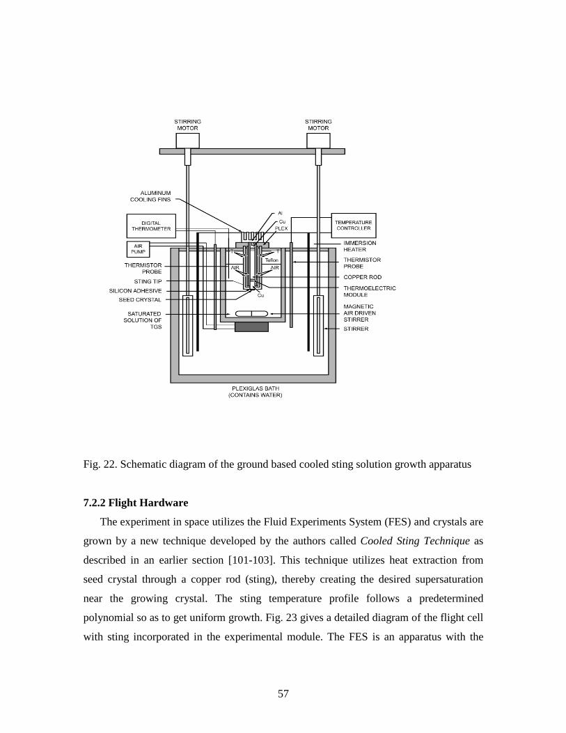
57
Fig. 22. Schematic diagram of the ground based cooled sting solution growth apparatus
7.2.2 Flight Hardware
The experiment in space utilizes the Fluid Experiments System (FES) and crystals are
grown by a new technique developed by the authors called Cooled Sting Technique as
described in an earlier section [101-103]. This technique utilizes heat extraction from
seed crystal through a copper rod (sting), thereby creating the desired supersaturation
near the growing crystal. The sting temperature profile follows a predetermined
polynomial so as to get uniform growth. Fig. 23 gives a detailed diagram of the flight cell
with sting incorporated in the experimental module. The FES is an apparatus with the

58
crystal growth cell as an integral part. It was developed by NASA and fabricated by TRW,
CA
Fig. 23 Flight Crystal Growth Cell designed and developed by NASA

59
The cell is designed to allow a variety of holographic diagnostics and real time schlieren
viewing of the crystal and the surrounding fluid. Schlieren images are transmitted down
link as black and white video to reveal flow patterns and variation in fluid density.
Holograms that are recorded in space give 3-D information that leads to quantitative
determination of concentration fields surrounding the crystal and motion of particles if
present to determine g-jitters. The modified FES incorporates holographic tomography
which enables the taking of optical data through the cell at multiple angles. During SL-3
mission, two TGS crystals (named FES-2 and FES-3) were grown using (001) oriented
seed-type disc (as shown in Fig. 24). The objectives of IML-1 flight experiments were:(a)
to grow TGS crystals; (b) to perform holographic tomography of fluid field in the test cell
in three dimensions; (c) to study the fluid motion due to g-jitter by multiple exposure
holography of tracer particles (200, 400, 600 micrometers) and ; (d) to study the influence
of g-jitter on crystal quality and growth rate. One of the authors (R. B. Lal ) was the
Principal Investigator of Spacelab-3 and IML-1 experiments. The Co-Investigators were
A. K. Batra, J. Trolinger and W. R. Wilcox. During the IML-1 flight, due to serious
hardware problems, only one TGS crystal was grown on a (010) oriented seed crystal.
The growth surface of seed crystal was a natural (010) face (unlike experiments
performed in SL-3 in which processed seeds were used.,) cut from a polyhedral TGS
crystal, with a thickness of about 3.5 mm. In TGS crystal growth rate is fast (maximum)
in [010] direction. On ground, good quality crystals are grown on (001) oriented seed
because the growth on an (010) face is non-uniform and multifaceted. Thus, it was
important to investigate the growth on an (010) oriented seed in the absence of buoyancy
driven convection, where growth is expected to be mainly diffusion controlled. This
crystal was grown with the undercooling of 4 °C for about 4 hours. The growth rate was
estimated to be about 1.6mm/day and quality of the grown crystal was substantially good.
It can be attributed to a smooth transition from dissolution to growth in space experiment.

60
Fig. 24 TGS Seed crystals used for Growth Runs on NASA First International
Microgravity Laboratory-1 (IML-1) Mission
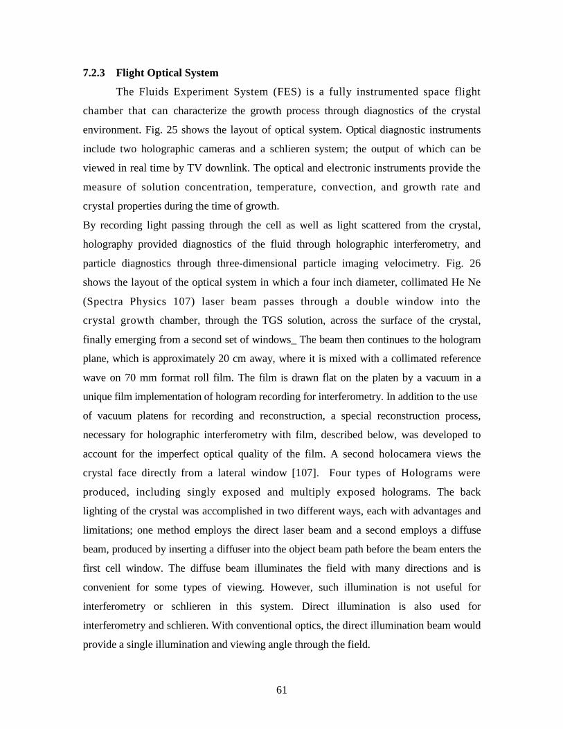
61
7.2.3 Flight Optical System
The Fluids Experiment System (FES) is a fully instrumented space flight
chamber that can characterize the growth process through diagnostics of the crystal
environment. Fig. 25 shows the layout of optical system. Optical diagnostic instruments
include two holographic cameras and a schlieren system; the output of which can be
viewed in real time by TV downlink. The optical and electronic instruments provide the
measure of solution concentration, temperature, convection, and growth rate and
crystal properties during the time of growth.
By recording light passing through the cell as well as light scattered from the crystal,
holography provided diagnostics of the fluid through holographic interferometry, and
particle diagnostics through three-dimensional particle imaging velocimetry. Fig. 26
shows the layout of the optical system in which a four inch diameter, collimated He Ne
(Spectra Physics 107) laser beam passes through a double window into the
crystal growth chamber, through the TGS solution, across the surface of the crystal,
finally emerging from a second set of windows_ The beam then continues to the hologram
plane, which is approximately 20 cm away, where it is mixed with a collimated reference
wave on 70 mm format roll film. The film is drawn flat on the platen by a vacuum in a
unique film implementation of hologram recording for interferometry. In addition to the use
of vacuum platens for recording and reconstruction, a special reconstruction process,
necessary for holographic interferometry with film, described below, was developed to
account for the imperfect optical quality of the film. A second holocamera views the
crystal face directly from a lateral window [107]. Four types of Holograms were
produced, including singly exposed and multiply exposed holograms. The back
lighting of the crystal was accomplished in two different ways, each with advantages and
limitations; one method employs the direct laser beam and a second employs a diffuse
beam, produced by inserting a diffuser into the object beam path before the beam enters the
first cell window. The diffuse beam illuminates the field with many directions and is
convenient for some types of viewing. However, such illumination is not useful for
interferometry or schlieren in this system. Direct illumination is also used for
interferometry and schlieren. With conventional optics, the direct illumination beam would
provide a single illumination and viewing angle through the field.

62
Fig. 25 Modified FES Optical System with various components

63
HOE 1'-Note that ray emerges at an angle to simplify separation.
A-Angle between optical axis and space shuttle axis M-mirror, BS-
Beamsplitter, C-crystal, O-lens, D-removable diffusor F1-Hologram 1, F2-
Hologram 2, L-HeNe laser underneath, S-side window
Fig. 26. Detailed Optical layout for the Fluid Experiment System (FES) designed and
developed by TRW
Our previous experience in Spacelab 3 had taught us that more than one
viewing angle is desirable. We achieved multiple viewing angles in IML-1 through the
use of windows equipped with holographic optical elements (HOEs). The input window
contains HOEs that convert the single input beam into three beams that pass over the
crystal at angles of 0° and ± 23.5°. The opposite window contains HOEs that redirect
these beams to the recording film plane so that they can all be recorded and again
separated during reconstruction. Consequently, each recording comprises three
superimposed, but independently viewable holograms. The schlieren system is
viewed by T`; allowing real time viewing both by the crew and by the TV downlink. A

64
primary use of the schlieren system is to view and judge the transition of the crystal
from a dissolution phase to a growth phase since control of this transition is considered to
be critical in producing a high quality crystal. The knife edge in the schlieren system was
set so that when the crystal was dissolving, light rays entering the resulting higher
refractive index region above the crystal would be refracted in the direction of the
crystal be removed by the knife edge, and appear dark in the image. When the transition
from dissolving to growing was made, the region immediately above the crystal would be
depleted of solute, thus reducing the refractive index and causing the refracted rays to
pass above the knife edge, causing a bright region to appear above the crystal within
the larger, dark region of higher concentration. The method proved to be an extremely
sensitive way to identify the transition from dissolving to growth.
7.3 Results and Discussion
The flight TGS crystals were examined with a high-resolution monochromatic
synchrotron X-radiation diffraction technique, both before and after slicing for the
fabrication of infrared detectors to check the lattice regularity, identify inclusions and
dislocations, draw inferences about growth mode and stability, and locate the interface
between the seed and the new growth. The experiments were performed at the National
Synchrotron Light Source at Brookhaven National Laboratory in collaboration with Dr.
Bruce Steiner of the United States National Institute of Standards and Technology (NIST).
The performance of materials is determined by their structure; in this performance,
irregularity typically plays a leading role. The growth of crystals in low-g has long been
of interest because of anticipation that reduction in gravitational forces would strongly
affect crystal growth and therefore the nature of resulting irregularities. Many factors
affect crystal growth, and because these can interact strongly with one another, the
understanding of the structural variation necessary for its effective exploitation has not
been fully achieved. A knowledge of irregularities in space and earth grown crystals,
developed in conjunction with an understanding their genesis and detailed affects on
properties, would be an important challenge. Such knowledge is expected also to
contribute to dramatically improve single crystal production, both in space and on the
earth. The local acceptance angle for diffraction from the uncut flight TGS-1 crystal, 1-2
arc seconds (Fig. 27), indicates extraordinary crystal quality [108]. Polystyrene particles

65
that had been included in the space-grown material in IML-1 experiment are observed as
small imperfections in Fig. 27(b). Also, clearly distinguishable in Fig. 27 (b) is the
faceted growth mode. Two sets of edge dislocations in the seed, one [101]-oriented and
the other [001]-oriented, were noted as well in images taken in Laue geometry; but they
appear not to have affected the space growth. Observation of the cut edge of the crystal,
Fig. 27(d), shows continuity between the seed at the top. The demarcation between the
seed and the space-grown material is indistinct. High-resolution imaging of terrestrial
crystals has shown that the surface treatment of the seed crystal is critical to growth
perfection. The ground control TGS crystals were of extremely high perfection. Slice
next to many possible flight seeds were examined by high-resolution diffraction imaging.
The selection of the flight seed was based on the perfection of the slice next to the seed
crystal.
Fig. 27. High Resolution Synchrotron X-Ray Radiation Diffraction Imaging of 1-g and
µg Grown TGS Crystals

66
Infrared detectors from the flight and ground control crystals were fabricated at
EDO/Barnes Engineering Division, Shelton, CT. The detectivity (D*) and other
parameters for these infrared detectors are shown in Fig. 28. The detector characteristics
are given in Table 5. The detectivity (D*) for I.R. detectors fabricated from the IML-1
crystal shows an improvement over the ground grown crystals and crystals grown on
Spacelab 3.
The particles motion of three different size particles were mapped using the
techniques described elsewhere [106, 107]. The combined effects of fluid convection,
particle interaction, residual gravity, shuttle maneuvers, and g-jitters have been observed.
However, the interferograms show several noteworthy features. When the crystal enters a
growth phase, the solution in the region near the crystal is depleted of solute, thus
reducing its refractive index below the surrounding fluid, creating a hemispherical cap of
fringes over the crystal as show in Fig.29. The stability of this cloud in the interferograms
confirmed that the crystal was growing in a diffusion controlled process. The cloud did
show, however, that the process was not completely axisymmetric, a condition by
equipment problems that were encountered during the mission.

67
Fig. 28. Relevant parameters of infrared detectors fabricated from 1-g and micro-g grown
TGS crystals
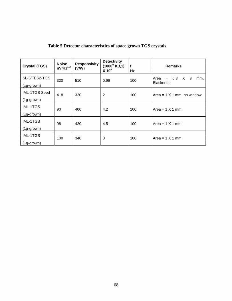
68
Table 5 Detector characteristics of space grown TGS crystals
Crystal (TGS) Noise nV/Hz1/2
Responsivity (V/W)
Detectivity Remarks (1000o K,f,1) f
X 108 Hz
SL-3/FES2-TGS 320 510 0.99 100 Area = 0.3 X 3 mm, Blackened
(µg-grown)
IML-1TGS Seed 418 320 2 100 Area = 1 X 1 mm, no window (1g-grown)
IML-1TGS 90 400 4.2 100 Area = 1 X 1 mm (µg-grown)
IML-1TGS 98 420 4.5 100 Area = 1 X 1 mm (1g-grown)
IML-1TGS 100 340 3 100 Area = 1 X 1 mm
(µg-grown)
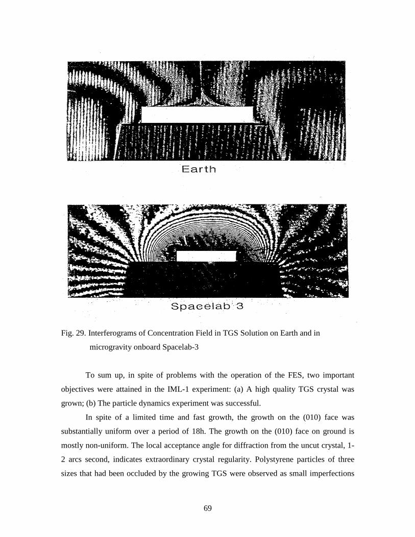
69
Fig. 29. Interferograms of Concentration Field in TGS Solution on Earth and in
microgravity onboard Spacelab-3
To sum up, in spite of problems with the operation of the FES, two important
objectives were attained in the IML-1 experiment: (a) A high quality TGS crystal was
grown; (b) The particle dynamics experiment was successful.
In spite of a limited time and fast growth, the growth on the (010) face was
substantially uniform over a period of 18h. The growth on the (010) face on ground is
mostly non-uniform. The local acceptance angle for diffraction from the uncut crystal, 1-
2 arcs second, indicates extraordinary crystal regularity. Polystyrene particles of three
sizes that had been occluded by the growing TGS were observed as small imperfections

70
in the grown crystal. The observations of the cut edge of the flight crystal (TGS-1) show
continuity between the seed at the bottom and the space growth at the top, indicating a
high degree of epitaxy of the space grown material. The demarcation between the seed
and the space grown material is indistinct, indicating a smooth transition from dissolution
to growth so that solvent inclusions are not formed between the seed and the grown layer.
Experiments on earth have shown that such inclusions tend to result in dislocations that
propagate through subsequently grown material and degrade properties. The infrared
detectors fabricated from the TGS-1 flight crystal show improved detectivity (D*) com-
pared to ground samples and even with detectors fabricated from crystals grown on
Spacelab-3. The dielectric loss in the IML-1 crystal is lower than in ground crystals and
in crystals grown in Spacelab-3.
8.0 Protein Crystal Growth
The human body contains thousands of different proteins, which play essential
roles in maintaining life. A protein’s structure determines the specific role that proteins
play in the human body; however, researchers lack detailed knowledge about the
structures of many proteins. The crystallization of proteins has three major applications:
(1) structural biology and drug design, (2) bio-separations, and (3) controlled drug
delivery. In the first application, the protein crystals are used with the techniques of
crystallography to ascertain the three-dimensional structure of the molecule. This
structure is indispensable for correctly determining the often complex biological
functions of these macromolecules. The design of drugs is related to this, and involves
designing a molecule that can exactly fit into a binding site of a macromolecule and block
its function of the disease pathway. Producing better quality crystals will result in more
accurate 3D protein structure, which in turn means its biological function can be known
more precisely, also resulting in improved drug design. The second application: bio-
separations refer to the downstream processing of the products of fermentation. Typically,
the desired product of the fermentation process is a protein (e.g. insulin) , which then
needs to be separated from biomass. Crystallization is one the commonly employed
techniques for separation of protein. It has the advantage of being a benign separation
process, that is, it does not cause the protein to unfold and lose its activity. The other
application of protein: controlled drug delivery is also very important. Most drugs are
71
cleared by the body rapidly following administration, making it difficult to achieve a
constant desired level over a period of time. When the drug is a protein such as insulin or
Alfa-interferon, administrating the drug in the crystalline form shows promise of
achieving such controlled delivery. The challenge is to produce crystals of relatively
uniform size so that dosage can be prescribed correctly.
8.1 Protein Crystal Growth Methods
Protein crystallization is inherently difficult because of the fragile nature of protein
crystals. Proteins have irregularly shaped surfaces, which result in the formation of large
channels within any protein crystal. Therefore, the no-covalent bonds that hold together
the lattice must often be formed through several layers of solvent molecules. In addition,
to overcoming the inherent fragility of protein crystals, the successful production of x-ray
worthy crystals is dependent upon a number of environmental factors because so much
variation exists among proteins, with each individual requiring unique conditions for
successful crystallization. Therefore, attempting to crystallize a protein without a proven
protocol can very tedious. Some factors that require consideration are protein purity, pH,
concentration of protein, temperature, and the precipitants. In order to initiate
crystallization the protein solution has to be brought to a thermodynamically unstable
state of supersaturation. The solution can be brought back to the stable equilibrium state
through precipitation of the protein, which is the most frequent process, or through
crystallization. The supersaturation state can be achieved by several techniques:
evaporation of solvent molecules, change of ionic strength, change of pH, change of
temperature or change of some other parameter.
Two of the most commonly used methods for protein crystallization fall under the
category of vapor diffusion [109-2-110]:
(i) Hanging drop method
(ii) Sitting drop method
Both the above cited methods entail a droplet containing purified protein, buffer and
precipitants in higher concentration. Initially, the droplet of protein solution contains an
insufficient concentration of precipitant for crystallization, but as water vaporizes from
the drop and transfer to the reservoir, the precipitant concentration increases to a level
optimal for crystallization. Since the system is in equilibrium, these optimum conditions

72
are maintained until the crystallization is complete. Figures 30 and 31 depict the hanging
drop and sitting drop systems, respectively. The hanging drop method differs from the
sitting drop method in the vertical orientation of the protein solution drop within the
system. It is important to mention that both methods require a closed system that is, the
system must be sealed off from outside using a airtight container. It is worthy of
mentioning that reservoir solution usually contains buffer and precipitant. Protein
solution contains the same compounds, but in lower concentrations. The protein solution
may also contain trace metals or ions necessary for precipitation . For instance, insulin is
known to require trace amounts of zinc for crystallization.
Fig. 30 Schematic diagram of hanging drop method
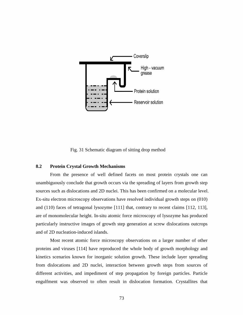
73
Fig. 31 Schematic diagram of sitting drop method
8.2 Protein Crystal Growth Mechanisms
From the presence of well defined facets on most protein crystals one can
unambiguously conclude that growth occurs via the spreading of layers from growth step
sources such as dislocations and 2D nuclei. This has been confirmed on a molecular level.
Ex-situ electron microscopy observations have resolved individual growth steps on (010)
and (110) faces of tetragonal lysozyme [111] that, contrary to recent claims [112, 113],
are of monomolecular height. In-situ atomic force microscopy of lysozyme has produced
particularly instructive images of growth step generation at screw dislocations outcrops
and of 2D nucleation-induced islands.
Most recent atomic force microscopy observations on a larger number of other
proteins and viruses [114] have reproduced the whole body of growth morphology and
kinetics scenarios known for inorganic solution growth. These include layer spreading
from dislocations and 2D nuclei, interaction between growth steps from sources of
different activities, and impediment of step propagation by foreign particles. Particle
engulfment was observed to often result in dislocation formation. Crystallites that

74
impinged on the interface became either epitaxially aligned with main crystal, or
remained misaligned and caused various defects during further growth. There appears to
be even some indication of kinetic roughening on certain facets of some proteins [115].
8.3 Protein Crystal Growth in Microgravity
The microgravity environment aboard space craft in low Earth orbit provides a
convection and sedimentation free environment for the study and applications of fluid-
based systems. With the advent of the United States’ Space Shuttle, scientists had regular
access to such environments and many experiments were initiated, including those in
protein crystallization. After many trials it became clear that for several proteins,
crystallization in microgravity environment resulted in bigger and better crystals. In some
instances, crystals that could not be crystallized on the ground at all were found to
crystallize in space. Conversely, for numerous proteins the space environment was found
to be no better or was worse than ground-based conditions. As a result of these
observations, NASA has become one of the leading federal agencies in prompting and
funding protein crystallization research. Efforts are directed at both utilizing the space
environment to improve the crystallization of novel proteins and in fundamental studies
of the causes (if any) of the improvement in protein crystals produced in microgravity.
The results from flying more, and studying in more detail, have “significantly altered”
attitudes towards space-based protein crystal growth. “Persuasive explanations” have
emerged, and a strong theoretical model has emerged to explain why space-based growth
is better.
Since the inception of protein crystal growth in microgravity research by Littke [118],
several research groups have developed microgravity hardware and experiments [118-
123]. Some of those are listed below:
(i) Hand-held protein crystallization apparatus for microgravity (HH-PCAM)
[124]
(ii) Diffusion-controlled crystallization apparatus for microgravity (DCAM)
[125]
(iii) High-density protein crystal growth system (HDPCG) [126]
(iv) Protein crystal growth facility (PCF) [127]

75
(v) A multi-user facility-based protein crystallization apparatus for microgravity
(PCAM) [124]
(vi) Advanced protein crystallization facility (APCF) [125]
Several thousand individual protein crystal growth experiments have been flown using
the PCAM facility hardware aboard the US Space Shuttle. According to developer of this
facility hardware represents a pioneering development in design and deployment of space
flight hardware which are based on disposable interface elements [124]. Furthermore, it
has resulted in an ultra high resolution structure and first example of neutron diffraction
achieved as a result of protein crystal growth in microgravity [127]. Additionally, using
this facility, fundamental differences in protein partitioning in microgravity have been
documented which represent the first direct experimental observation of the factors
contributing to quality improvements in the growth of protein crystals in microgravity
[128]. The other important hardware referred to as diffusion-controlled crystallization
apparatus for microgravity (DCAM) which utilizes the dialysis method and allows the
equilibration rate of each individual experiment to be passively controlled from several
days to several months. It is worth mentioning that precision control rate of
supersaturation has routinely produced macro crystals of size 5 mm to 1. 25 cm for a
variety of protein in this hardware. Analysis of serum albumin, ferritin, lysozyme,
bacteriorhodopsin, and nucleosome core particles exhibit superior diffraction properties
as compared to ground-based controls [125}. Further improvements of the hardware is
going on for International Space Station where scientists can learn more about the
mechanisms of the growth, and X-ray analysis can be done aboard the Space Station
[126].
9.0. CONCLUDING REMARKS
Bulk high quality single crystals are required for use in fabricating devices for
various technological applications. Since crystal growth is a complicated process that
depends on many parameters that can interact and the complete process is not well
understood. This is one of the reasons to grow crystals in microgravity of space to
separate omnipresent convection on Earth and have only diffusion controlled growth.
Authors have attempted to give an comprehensive overview of the various problems
encountered in the solution growth of single crystals on Earth and in space experiment

76
based on their experience for almost 3 decades. The solutions of the various problems
encountered during growth on ground and in spaceflight experiments are described. This
chapter shall serve as a foundation for those who desire to initiate a research program in
the growth of bulk single crystals of technological importance that can be grown from
low temperature solution technique. A brief review of the crystal growth fundamentals is
presented including key techniques for solution crystal growth such as solubility
determination, design of various crystal growth systems including mechanical and
electronic crystal motor reciprocating arrangement. Three generations of modifications to
solution crystallizers designed and fabricated in the laboratory and the crystallizer for
space growth cooled sting technique advanced by the authors are described. A number of
solution grown crystals grown at Alabama A&M University are shown. A detailed
description of the crystal growth experiments on an important infrared material triglycine
sulphate and difficulties encountered in the space crystal growth experiment aboard space
shuttle in NASA Spacelab-3 and the first International Microgravity Laboratory (IML-1)
missions is given. Since basic principles of solution growth technique are shared by
protein crystal growth, basic techniques of protein crystal growth are briefly mentioned
and the efforts of protein crystal growth in microgravity are also discussed.
ACKNOWLEDGEMENTS
The authors are grateful for helpful discussions with a number of graduate students and
other physics faculty in the department of physics at Alabama A&M University. Authors
are thankful to Mr. Garland Sharp for his expert machining work and Mr Jerry Johnson
for his glass blowing jobs in the design of various crystal growth systems described in
this work. This work was partially supported under NSF-HBCU RISE program HRD-
0531183 and U.S. Army Space and Missile Defense Command, Contract W9113M-04-C-
0005. Two of the authors (MDA and RBL) would like to acknowledge support from
NASA Administrator’s Fellowship Program (NAFP) through United Negro College Fund
Special Programs (UNCFSP) Corporation under their Contract No. NNG06GC58A.
77
References
1. H. A. Meirs and F. Isaac: The spontaneous crystallization, Proc. Roy. Soc. London A79, 322-325 (1987).
2. K. Sangwal: Growth kinetics and surface morphology of crystals grown from
solutions: Recent observations and their interpretations, Prog. Cryst. growth and
Charact. Mat. 36(3), 163-248 (1998).
3. I. F. Nicolau: Growth kinetics of potassium-dihydrogen phosphate crystals in
solution, Kristall and Technik 9(11), 1255-1263 (1974).
4. R. Janssen-Van Rosmalen and P. Bennema, J. Garside: The influence of volume
diffusion on crystal growth, J. Cryst. Growth 29, 342-352 (1975).
5. A. Chianese: Growth and dissolution of sodium perborate in aqueous solutions by
using RDC technique, J. Cryst. Growth 91, 39-49 (1988).
6. K. Sangwal: On the mechanism of crystal growth from solutions, J. Cryst. Growth
192 , 200-214 (1998).
7. Y. Wang, X. L. Yu, D. I. Sun, S. T. Yin: Mass transport and growth kinetics
related to the interface supersaturation oh lithium formate monohydrate, Cryst.
Res. Technol. 36 (4-5), 441-448 (2001).
8. N. Zaitseva, L. Carman: Rapid growth of KDP-type crystals, Prog. Cryst. growth
and Charact. Mat. 43, 1-118 (2001).
9. I. V. Melikhov, L. B. Berliner: Crystallization of salts from supersaturated
solutions ; diffusion kinetics, J. Cryst. Growth 46, 79-84 (1979).
10. P. Bennema: Sprial growth and surface roughening: development since Burton,
Cabrera and Frank, J. Cryst. Growth 69, 182-197 (1984).
11. X. Y. Liu, K. Malwa , K. Tsukamoto: Heterogeneous two dimension nucleation
and growth kinetics, J. Chem. Phys. 106(5), 1870-1879 (1997).
12. Alexander F. Izmailov, Allan S. Myerson: Momentum and mass transfer in
supersaturation solutions crystal growth from solution, J. Cryst. Growth 174, 263-
368 (1997).
13. Miroslawa Rak, Karek Izdebski, Andrzej Brozi: Kinetic Monte Carlo study of
crystal growth from solution, Computer Phys. Comm., 138, 250-263 (2001).

78
14. F. Rosenberger, B. Mutaftschiev (ed.): Interfacial Aspects of Phase
Transformation ( D. Reidel Publishing Company 1982).
15. A. A. Chernov: Present day understanding of crystal growth from aqueous
solutions, Prog. Cryst. growth and Charact. 26, 121-151 (1993).
16. Rajeev Mohan, Allan S. Myerson: Growth kinetics: a thermodynamic approach,
Chem. Engn. Sci. 57 , 4277-4285 ( 2002).
17. C. M. Pina, A. Putnis, J. M. Astilleros: The growth mechanisms of solid solutions
crystallization from aqueous solutions, Chemical Geology 204, 145-161 (2004).
18. I. Sunagawa, K. Tsukamoto, K. Maiwa, K. Onuma: Growth and perfection of
crystals from aqueous solution: Case studies on Barium nitrate and K-Alum, Prog.
Cryst. and Charact. 30, 153-190 (1995).
19. William R. Wilcox: Influence of convection on the growth of crystals from
solution, J. Cryst. Growth 65, 133-142 (1983).
20. Ivan V Markov: Crystal Growth for Beginners (World Scientific, NJ, USA 2004)
21. Ichiro Sunagawa: Crystals Growth, Morphology and Perfection (Cambridge
University Press, Cambridge, UK 2005).
22. Tomoya Ogawa: A phenomenological Analysis of crystal growth from solutions
as an irreversible process, Jap. J. Appl. Phys. 16(5), 689-695 (1977).
23. S. Veintemillas-Verdaguer: Chemical aspects of the effect of impurities in crystal
growth, Prog. Cryst. Growth and Charact. 32, 76-109 (1996).
24. K. Sangwal: Kinetics effects of impurities on the growth of single crystals from
solutions, J. Cryst. Growth 203, 197-212 (1999).
25. I. Owczarek, K. Sangwal: Effect of impurities on the growth of KDP crystals:
Mechanism of adsorption on (101) faces, J. Cryst. Growth 102, 574-580 (1990).
26. K. Sangwal: Effects of impurities on the crystal growth processes, Prog. Cryst.
and Charact. 32, 3-43 (1996).
27. E. Kirkova, M. Djarova, B. Donkova: Inclusions of isomorphism impurities
during crystallization from solutions, Prog. Cryst. Growth and Charact. 32, 111-
134 (1996).
79
28. M. Rauls, K. Bartosch, M. Kind, St. Kuch, R. Lacmann, A. Mersmann: The
influence of impurities on crystallization kinetics-a case study on ammonium
sulfate, J. Cryst. Growth 312, 116-128 (2000).
29. E. Mielniczek-Brzoska, K. Gielzak-Kocwin, K. Sangwal: Effects of Cu(II) ions
on the growth of ammonium oxalate monohydrate crystals from aqueous
solutions: growth kinetics, segregation coefficient and characterization of
incorporation sites, J. Cryst. Growth 212 , 532-542 (2000).
30. K. Sangwal, E. Mielniczek-Brzoska, J. Bore: Effect of Mn(II) ions on the growth
of ammonium oxalate monohydrate crystals from aqueous solutions: Growth
habit and surface morphology, Cryst. Res. Technol. 38(2), 103-112 (2003).
31. Noriaki Kubota, Masaaki Yokota, J. W. Mullin : Supersaturation dependence of
crystal growth in solutions in the presence of impurity, J. Cryst. Growth 182 , 86-
94 (1997).
32. K. Sangwal, E. Mielniczek-Brzoska : On the effect of Cu(II) impurities on the
growth kinetics of ammonium oxalate monohydrate crystals from aqueous
solutions, Cryst. Res. Technol. 36 (8-10), 837-849 (2001).
33. K. Sangwal, E. Mielniczek-Brzoska, J. Bore: Study of segregation coefficient of
cationic impurities in ammonium oxalate monohydrate crystals during growth
from aqueous solutions, J. Cryst. Growth 244, 183-193 (2002).
34. K. Sangwal, T. Palcznska: On the supersaturation and impurity concentration
dependence of segregation coefficient in crystals grown from solutions, J. Cryst.
Growth 212, 522-531 (2002).
35. Sv. P. Delineshev: Growth of crystals in the presence of impurities, a hypotheses
based on a kinetic approach, Cryst. Res. Technol. 33 (6) 891-897 (1998).
36. K. Sangwal: Kinetic effects of impurities on the growth of single crystals from
solutions, J. Cryst. Growth 203, 197-212 (1999).
37. A. S. Myerson and S. M. Jang: A comparison of binding energy and metastable
zone width for adipic acid with various additives. J. Cryst. Growth 156, 459-466
(1995).
80
38. D. Aquilano, M. Rubbo, G. Mantovani, G. Sgualdino and G. Vaccari: Equilibrium
and growth forms of sucrose crystals in the {h0l} zone, J. Cryst. Growth 74, 10-
20 (1986).
39. D. Aquilano, M. Rubbo, G. Mantovani, G. Sgualdino and G. Vaccari: Equilibrium
and growth forms of sucrose crystals in the {h0l}zone, J. Cryst. Growth 83, 77-83
(1987).
40. A. A. Chernov and V. V. Sipyagin: Peculiarities in crystal growth aqueous
solutions connected with their structure, in Current Topics in Materials Science, E.
Kaldis, Ed., Vol 5 pp279-333, North-Holland, Amsterdam, 1980.
41. Crystal growth of technologically important electronic materials, K. Byrappa, H.
Klapper, T. Ohachi, R. Fornari Eds. Allied Publishers PVT. Limited, New Delhi,
2003.
42. M. D. Aggarwal, T. Gebre, A. K. Batra, M. E. Edwards, R. B. Lal, B. G. Penn, D. O. Frazier:Growth of nonlinear optical materials at Alabama A&M University, Proc. of SPIE, vol.4813: Crystal Materials for Nonlinear Optical Devices and Microgravity Science,52-65 (2002).
43. M. D. Aggarwal, W. S. Wang, K. Bhat, P. G. Penn and D. O. Frazier: Photonic Crystals: Crystal growth processing and physical properties, in Handbook of Advanced Electronic and Photonic Materials and Devices, H. S. Nalwa. Ed. Academic Press, New York, vol.9 pp193-228 (2001)
44. Heinz K. Henisch: Crystal Growth in Gels (Dover Publications, Inc. New York
1970).
45. A. F. Barton, Handbook of solubility parameters and other cohesion parameters,
CRC Press, Boca Raton, FL 1983.
46. J. Novotny: A crystallizer for the investigation of conditions of growth of single
crystals from solutions, Kristall and Technik 6(3), 343-352 (1971)
47. M.D. Aggarwal, J. Choi, W. S. Wang, K. Bhat, R. B.Lal, R.B., A.D Shields, B. G.
Penn, D. O. Frazier: Solution growth of a novel nonlinear optical material: L-
histidine tetrafluoroborate, J. Cryst. growth 204, 179-182 (1999).
48. W. S. Wang, M. D. Aggarwal, J.Choi. K.Bhat, T. Gebre, A.D Shields, B. G. Penn,
D. O. Frazier: Solvent effects and polymorphic transformation of organic
nonlinear optical crystal L-pyroglutamic acid in solution growth processes, I.

81
Solvent effects and growth morphology, J. Cryst. growth 198/199, 578-582
(1999).
49. C. Owens, K. Bhat, W. S. Wang, , A. Tan, M.D. Aggarwal, P.G. Penn, D.O.
Frazier: Bulk growth of high quality nonolinear optical crystals of L-arginine
tetrafluoroborate (L-AFB), J. Cryst. Growth 225, 465-469 (2001).
50. R. B. Lal, H. W. Zhang, W. S. Wang, M. D. Aggarwal, Howard W. H. Lee, B. G.
Penn: Crystal growth and optical properties of 4-aminobenzophenone crystals for
NLO applications, J. Cryst. growth 174, 393-397 (1997).
51. H. W. Zhang, A. K. Batra, R. B. Lal: Growth of large methyl-(2,4-dinitrophenyl)-
aminopropanoate: 2-methyl-4-nitroaniline crystals for nonlinear applications, J.
Cryst. Growth 137, 141-144 (1994).
52. Michelle Renee Simmons: MS thesis ”An investigation of crystals matrices of
single crystals doped with rare earth ions” Alabama A&M University, Normal,
AL. (USA) 2002.
53. Jiann-Min Chang, Ashok K. Batra and Ravindra B. Lal: Growth and
characterization of doped TGS crystals for infrared devices, Cryst. Growth &
Design 2(5), 431-435 (2002)
54. R. B. Lal and M. D. Aggarwal: Reciprocating Crystallizer: Automatic crystallizer
grows crystals from aqueous solutions, NASA Tech. Briefs 8, 419 (1984)
55. M. D. Aggarwal and R. B. Lal: Simple low-cost reciprocating crystallizer for
solution crystal growth, Rev. Sci. Instr. 54, 772-773 (1983)
56. A. K. Batra and S. C. Mathur, Reciprocating arrangement for solution crystal
growth, Res. Indust. 20, 29 (1984).
57. A. K. Batra, C. R. Carmichael-Owens, M. Simmons, M. D. Aggarwal and R. B.
Lal : Design of a solution crystal growth crystallizer with versatile electronic
reciprocal motion control for a crystal holder, Cryst. Res. Technol. 40(8), 757-760
(2005).
58. Ashok K. Batra, Mohan D. Aggarwal and Ravindra B. Lal: Growth and
characterization of doped DTGS crystals for infrared sensing devices, Mat. Lett.
57, 39-43 (2003).

82
59. Franco Jona and S. Shirane: Ferroelectric Crystals (Dover Publications Inc., New
York, USA 1993)
60. R. B. Lal and A. K. Batra: Growth and properties of triglycine (TGS) sulfate
crystals: Review, Ferroelectrics 142, 51-82 (1993)
61. E. A. D. White, J. D. C. Wood and V. M. Wood: The growth of large area,
uniformly doped TGS crystals, J. Cryst. Growth 32, 149-156 (1976).
62. B. Brezina, M. Havrankova, M. VASA: Enhanced growth of non-polar{001}
growth sectors of deuterated triglycine sulfate doped with L-alanine (LADTGS),
Cryst. Res. Technol. 27(1), 13-20 (1992).
63. S. Satapathy, S. K. Sharma, A. K. Karnal, V. K. Wadhawan, Effects of seed
orientation on the growth of TGS crystals with large (010) facets needed for
detector applications, J. Cryst. Growth 240 196-202 (2002).
64. Mohsen Banan, Growth of pure and doped triglycine sulfate crystals for
pyroelectric infrared detector applications, MS thesis, 1986 Alabama A&M
University, Normal, AL 35762, USA.
65. Deng Zhao-De: A new method of growth of ferroelectric crystal, Ferroelectrics 39,
1237 (1981).
66. F. Moravec and J. Novotny, Study on the growth of triglycine sulphate single
crystals, Kristall and Tecknik 7, 891-902 (1972).
67. W. K. Burton, N. Cabrera and F. C. Frank, Philos. Trans. R. Soc., London, 243,
299 (1951).
68. L. N. Rashkovich, Sov. Phys. Crystallog, 28, 454 (1983).
69. J. Novotny, F. Moravec and Z. Solc: The role of surface and volume diffusion in
the growth of TGS single crystals, Czech. J. Phys., B23, 261-266 (1973).
70. J. Novotny and F. Moravec: Growth of TGS from slightly supersaturated
solutions, J. Cryst. Growth 11, 329-335 (1971).
71. D. A. Reiss, R. L. Kroes and E. E. Anderson: Growth Kinetics of the (001) face of
TGS below the ferroelectric transition temperature, J. Cryst. Growth 84, 7-10
(1987).

83
72. F. Moravec and J. Novotny: A contribution to the study of the influence of
impurities on the growth and some physical properties of TGS single crystals,
Kristall and Technik 6(3), 335-342 (1971).
73. R. V. Whipps, R. S. Cosier and K.. L. Bye: Orthorhombic diglycine sulphate, J.
Mat. Sci., 7(12), 1476-1477 (1972).
74. E. Dominquez, R. Jimenez, J. Mendiola and E. J. Vivas: Diglycine sulphate- an
interesting new dielectric crystal species, J. Mat. Sci., 7(3), 363-364 (1972).
75. M. S. Tsedrik, V. N. Ulasen and G. A. Zaborovski: Kristall and Technik, 10(1),
49 (1975).
76. E. J. Weidmann, E. A. D. White and V. M. Wood: Induced growth anisotropy in
TGS crystals, J. Mat. Sci. Lett. 7, 719-720 (1972).
77. L. Szczepanska: Growth investigations of single crystal sulphates containing
molecular glycine groups, Kristall and Technik, 11, 265-271 (1976).
78. L.Prokopova, J. Novotny, Z. Micka, V. Malina, Growth of triglycine sulphate
crystals doped by cadmium phosphate, Cryst. Res. Technol., 36, 1189-1195
(2001)
79. G. R. Pandya and D. D. Vyas: On growth and morphological studies of TGS
single crystals, Cryst. Res. and Technol., 16, 1353-1358 (1981).
80. R.B. Lal, S. Etminan and A.K. Batra: Effect of simultaneous organic and
inorganic dopants on the characteristics of triglycine sulfate crystals, Proc. 9th
IEEE Intern. Symp on applications of Ferroelectrics, p.695-697 (1994)
81. M. Banan, A. K. Batra and R. B. Lal: Growth and morphology of triglycine
sulphate (TGS) crystals, J. Mat. Sci. Lett. 8, 1348-1349 (1989).
82. M. Banan, R. B. Lal, A. K. Batra and M. D. Aggarwal: Effect of poling on the
morphology and growth rate of TGS crystals, Cryst. Res. Technol. 24(3), K53
(1989).
83. N. Nakatani, Ferroelectric domain structure and internal bias field in DL-α-
Alanine-doped triglycine sulfate, Jpn. J. Appl. Phys. 30 (12A), 3445-3449 (1991).
84. J. Eisner, the physical properties of TGS single crystals, grown from aqueous
TGS solutions containing Aniline Phys. Status Solidi 43, K1-K4 (1977).

84
85. F. Moravec, J. Novotny, and J. Strajblova, Single crystals of triglycine sulphate
containing palladium Czech. J. Phys., 23, 855-862 (1977).
86. A. S. Sidorkin and A. M. Kostsov, Exoelectron emission from a ferroelectric
crystal of triglycine sulfate with defects, Soviet Physics-Solid State 33(8), 1383-
1384 (1991).
87. L. Yang, A. K. Batra and R. B. Lal: Growth and characterization of TGS crystals
grown by cooled sting technique, Ferroelectrics 118(1-4), 85 (1991).
88. N. Nakatani: Ferroelectric domain structure and Internal Bias Field in DL-α-
Alanine doped triglycine sulfate, Jap. J. Appl. Phys., 30, 3445-3449 (1991)
89. B. Brezina and M. Havrankova: Orientation of structure and crystals of TGS and
TGS doped with D, al or L, al, Cryst. Res. Technol, 20, 781-786 (1985).
90. G. M. Loiacono and J. P. Dougherty: Final Technical Report (contract no
DAAK70-77-C-0098) submitted to Night Vision and Electro-optics Laboratories,
Fort Belvoir, Virginia, 1978
91. O. W. Wang, C. S. Fang: Investigation of the solution status of TGS and ATGSP
crystals, Cryst. Res. Technol. 27, 245-251 (1992).
92. Selemani Seif, Kamala Bhat, Ashok K. Batra, Mohan D. Aggarwal, Ravindra
B.Lal: Effect of Cr(III) impurity on the growth kinetics of potassium dihydrogen
phosphate and triglycine sulfate grown from aqueous solutions, Mat. Lett. 58,
991-994 ( 2004).
93. V. A. Kuznetov, T. M. Okhrimenko, M. Rak: Growth promoting effect of organic
impurities on growth kinetics of KAP and KDP crystals, J. Cryst. Growth 193,
164- 173 (1998).
94. R, J, Davey in: E. J. de Jong, S. J. Jancic (Eds), Industrial Crystallization, vol 78 p
169 ( North-Holand, Amsterdam 1979)
95. K. Meera, R. Muralindharan, A. K. Tripathi, P. Ramasamy: Growth and
characterization of l-threonine, dl-threonine, l-methionine admixtured TGS
crystals, J. Crystal Growth 263, 524-531 (2004).
96. Genbo Su, Youping He, Hongzhi Yao, Zikong Shi, Qingjin: A new pyroelectric
crystal L-lysine-doped THS (LLTGS), J. Cryst. Growth 209 , 220-222 (2000).

85
97. G . Arunmozhi, E. De Matos Gomes, J. Ribeiro : Dielectric properties of L-
Asparagine doped TGS (Asp-TGS) crystals, Ferroelectrics 295, 87-95 (2003).
98. J. Novotny, J. Zelinkam F. Moravec: Boardband infrared detectors on the basis of
PATGS/Pt(IV) single crystals, Sensors and Actuators A 119, 300-304 (2005).
99. S. Kalainathan, M. Beatrice Margaret, T. Trusan: Morphological changes of L-
asparagine doped TGS crystal, Cryst. Engn. 5, 71-78 (2002)
100. http://www.nasa.gov/mission pages/shuttle/shuttlemissions/list main.html
101. R. B. Lal, R. L. Kroes: Solution growth of crystal on Spacelab-3, Proceedings of
the 24th AIAA Science Meeting, Reno, Nevada, Jan 6-8, 1985.
102. R. B. Lal, M. D. Aggarwal, R. L. Kroes, W. R. Wilcox: A new technique of
solution crystal growth, Phys. Status Solidi (A) 80, 547- 551 (1983).
103. A. K. Batra, R. B. Lal, M. D. Aggarwal : Electrical properties of TGS crystals
grown by new technique, J. Mat. Sci. Lett. 4, 1425-1427 (1985).
104. R. B. Lal, M. D. Aggarwal, A. K. Batra, R. L. Kroes: Solution growth of crystals
in zero-gravity, Final Technical Report, NASA contract number NAS8-32945
(1987).
105. L. Yang, A. K. Batra, R. B. Lal: Growth and characteristics of TGS crystals
grown by cooled sting technique, Ferroelectrics 118(1-4), 85-89 (1991).
106. R. B. Lal, A. K. Batra, J. D. Trolinger and W. R. Wilcox: TGS crystal growth
experiment on the first international microgravity laboratory (IML-1).
Microgravity Quarterly 4(3), 186-198 (1994).
107. R. B. Lal: Solution growth of crystals in low-gravity, Final Technical Report,
NASA Contract number NAS8-36634 (1995).
108. B. Steiner, R. Dobbyn, D. Black, H. Burdette, M. Kuriyama, R. Spal, L. van den
Berg, A. Fripp, R. Simchick, R. Lal, A. Batra, D. Mathiesen, B. Ditchek: High
resolution diffracting imaging of crystals grown in microgravity and closely
related terrestrial crystals, NIST Technical Note 1287 (1991).
109. Duncan E. McRee: Practical Protein Crystallography, San Diego: Academic
Press, 1993 (pp1-23).
110. Gale Rhodes: Crystallography Made Crystal Clear, pp8-10, pp29-38 (Academic
Press, San Diego 1993)
86
111. S. D. Durbin and G. Feher: Studies of crystal growth mechanisms of proteins by
electron microscopy, J. Mol. Biol. 212, 763-774 (1990).
112. E. Forsythe and M. L. Pusey: The effects of temperature and NaCl concentration
on tetragonal lysozyme face growth rates, J. Cryst. Growth 139, 89-94 (1994).
113. A. Nadaraja, E. L. Forsythe and M. L. Pusey: The averaged face growth rates of
lysozyme crystals: the effect of temperature, J. Cryst. Growth 151, 163-172
(1995)
114. W. Littke, C. John: Protein single crystal growth under microgravity, Science,
225, 203-204 (1984)
115. F. Rosenberger: Protein crystallization, J. Cryst. Growth 166, 40-54 (1996)
116. S. Gorti, E.L. Forsythe and M.L. Pusey: Measurable characteristics of lysozyme
crystal growth, Acta Cryst. D61, 837-843 (2005).
117. http://science.nasa.gov/ssl/msad/pcg/
118. W. Littke and C. John: Protein single crystal growth under microgravity, J.
Cryst. Growth, 76, 663-672 (1986)
119. L. J. DeLucas, F.L Suddath, R. S. Snyder, R. Naumann, M. B. Broom, M. Pusey,
V. Yost, B. Herren, D. Carter, B. Nelson, E. J. Meehan, A. McPherson, C. E.
Bugg: Preliminary investigations of protein crystal growth using the space shuttle,
J. Cryst. Growth 76, 681-693 (1986)
120. L. J. DeLucas, C. D. Smith, H. W. Smith, V. K. Senadhi, S.E. Senadhi, S. E.
Ealick, D. C. Carter, R. S. Snyder, P. C. Weber, F. R. Salemme, D.H. Ohlendorf,
H.M. Einspahr, L. L. Clancy, M. A. Navia, B. M. McKeever, T. L. Nagabhushan,
G. Nelson, A. McPherson, S. Koszelak, G. Taylor, D. Stammers, K. Powell, G.
Darby, C. E. Bugg: Protein crystal growth in microgravity, Science, 246, 651-653
(1989)
121. S.Simic-Stefani, M.Kawaji, H.U. Hu: G-jitter induced motion of a protein crystal
under microgravity, J. Cryst. Growth, 294,373-384 (2006).
122. A. McPherson: Virus and protein crystal growth on earth and in microgravity, J.
Phys. D, 26, B104-B112 (1993).
123. D. C. Carter, T. E. Dowling: Protein crystal growth apparatus for microgravity,
US Patent No. 5,643,540 (1997)

87
124. Daniel C. Carter, Brenda Wright, Teresa Miller, Jenny Chapman, Pam Twigg,
Kim Keeling, Kerry Moody, Melissa White, James Click, John R. Ruble, Joseph
X. Ho, Lawana Adcock-Downey, Tim Dowling, Chong-Hawn Chang, Paul Ala,
John Rose. B. C. Wang, Jean-Paul Declercq, Chrisitine Evrard, John Rosenberg,
Jean-Pierre Wery, Davis Clawson, Mark Wardell, W. Stallings, A. Stevens:
PCAM: a multi-user facility-based protein crystallization apparatus for
microgravity, J. Cryst. Growth 196, 610-622 (1999)
125. Daniel C. Carter , Brenda Wright, Teresa Miller, Jenny Chapman, Pam Twigg,
Kim Keeling, Kerry Moody, Melissa White, James Click, John R. Ruble, Joseph
X. Ho, Lawana Adcock-Downey, Gerard Bunick, Joel Harp : Diffusion-
controlled crystallization apparatus for microgravity (DCAM) : flight and
ground-based applications, J. Cryst. Growth 196, 602-609 (1999)
126. Lawrence J. DeLucas, K.M. Moore, M.M. Long, R. Rouleau, T. Bray, W. Crysel,
L. Weise : Protein crystal growth in space, past and future, J. Cryst. Growth 237-
239, 1646-1650 (2002)
127. J. P. Declereq, C. Evrard, D. C. Carter, B. S. Wright, G. Etienne, J. Parello: A
crystal of a typical EF-hand protein grown under microgravity diffracts x-rays
beyond 0.9 A resolution, J. Cryst. Growth 196, 595-601 (1999).
128. D. C. Carter, K. Lim, J. X. Ho, B. S. Wright, P. D. Twigg, T. Y. Miller, J.
Chapman , K. Keeling, J. Ruble, P. G. Vekilov, B. R. Thomas, F. Rosenberger, A.
A. Chernov: Lower dimmer impurity incorporation may result in higher
perfection of HEWL crystals grown in microgravity: A Case Study, J. Cryst.
Growth 196, 623-637 (1999).