solutions for solar energy - library.e.abb.com · circuit measurement system (cms) 32 solutions for...
TRANSCRIPT

Low- and medium-voltagecomponents, systems and services
— Solutions for solar energy


04– 05 Unlimited clean energy with zero emissions
06 – 07 The photovoltaic system - Components
08 – 15 Examples of photovoltaic applications
16 Key OEM supplier for top central inverter manufacturers
17 Key OEM supplier for top string inverter manufacturers
18 DC string boxes
19 Medium-voltage (MV) solutions
20 – 21 Product packages for solar plants
22 – 51 Products for DC side
52 – 73 Products for AC side
74 – 91 Medium-voltage products and services
92 – 98 Other products
03
— Summary

— Unlimited clean energy with zero emissionsABB and solar energy
Environment friendly energy
Energy is one of the biggest global challenges we face today and major companies are at the heart of this issue. This is because the world expects them to come up with new technologies and systems to produce energy with reduced pollution and greenhouse gas emissions, widely recognised as one of the main causes of global warming.
Clean energy from the sun
Renewable energy plays a fundamental role in future energy policy in the light of the mounting interest in safeguarding the environment and the search for more efficient uses of energy resources, with the recognition that traditional fossil fuels will not last forever. Against this background, the sun is unquestionably an energy source of huge potential, one that can be exploited without harming the environment. At any time, the hemisphere of the earth exposed to the sun receives over 50,000 TW of power, nearly 10,000 times the quantity of energy consumed all over the world.
ABB for solar energy
ABB has been a leading player in the solar power industry since the early 1990s when ABB developed an automation platform for the world’s first test facility for concentrating solar power technologies at the Plataforma Solar de Almería (PSA) in Spain. Since then, we have been involved at a pioneering stage in just about every type of photovoltaic (PV) and concentrating solar power (CSP) technology developed, be it in Europe, North America, Australia, North Africa or the Middle East. This has given us a unique expertise in how best to harness, control and store solar energy and efficiently convert it into a reliable power source, ready for transfer into the local grid. ABB’s portfolio of products, systems and solutions for the solar power industry is extensive. It ranges from complete power and automation solutions for CSP plants to commercial, industrial and residential rooftop PV installations.
04 S O LUTI O N S FO R S O L A R E N E RGY

On the manufacturing side, ABB supplies robots and robot-based systems for solar panel factories, and electrical, control and instrumentation solutions for silicon processing factories, the material that is used to make solar cells. And in smart grids, ABB is at the forefront in developing the technologies and solutions that will make possible the electrical transmission and distribution systems of the future. These systems will integrate traditional types of large-scale, centralized power generation with small-scale, localized types of renewable energy like solar and wind, creating a single optimized network with multi-directional power flows and realtime grid monitoring, able to operate as an efficient energy market.
Quality and sustainability, our key factors
For every activity and every product family, ABB is highly focused on environmental sustainability and safety. The environmental management systems, certified to ISO 14001, cover most of ABB operations and its products comply with the main International, European and North-American standards. The development of eco-compatible products, not containing any substances that can endanger or harm the environment, is imperative in all the R&D activities of ABB. The reliability and efficiency of a plant depend on many factors, related both to the entire plant and to the functional details of the single subsystems and items of equipment. The quality and safety of each product are essential to guarantee the maximum performance of the plants. The more complex a plant, the more profitable it is to turn to an experienced partner, capable of providing global solutions to respond substantially and effectively to all the needs of each single application, from design to maintenance. ABB, a global leader in the automation and energy industry for years, can support its clients in building large-sized plants, financed on the basis of the reliability and soundness of the supplier companies.
05
— The photovoltaic systemComponents
For the system to be considered a good investment, it must be able to last “in good condition” for at least 20 years, while being subjected to bad weather and intense sun exposure.
There is no doubt that what is generally referred to with the abbreviation BOS (Balance of System), or the “rest of the system” (electromechanical equipment for protection, switching, insulation and wiring) plays a specific role in ensuring adequate protection for the people and property connected to the system, as well as in the optimization of production over the course of time. From an economic point of view, even more so in respect to a normal electrical system, each single component in a photovoltaic system must be chosen above all based on its warranty date and its manufacturer.Each component must maintain its functional characteristics unchanged for the entire lifespan of the system and of the correlated investment.
The efficiency and quality of a system can be measured by the efficiency and quality of each single component: a fundamental factor for a photovoltaic system’s positive outcome is therefore the proper choice of components.
Just like any other electrical system, the installation of a photovoltaic system must be designed and implemented while taking into consideration the technological solutions and regulatory standards that can guarantee maximum operational safety and protection for those who must work on its structure.A relevant function is carried out by the breaking and protection devices, in the direct current system as well as in the downstream alternating current system. The variety of photovoltaic systems in terms of power, inverter type and type of hook-up to the public mains network (single-phase, three-phase, in low- and medium-voltage) requires careful selection of components by the designers and installers.
06 S O LUTI O N S FO R S O L A R E N E RGY

07
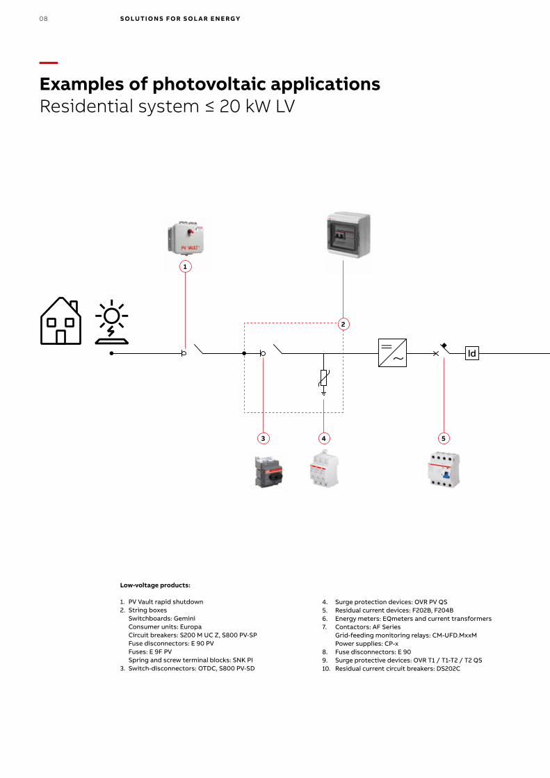
— Examples of photovoltaic applications Residential system ≤ 20 kW LV
Low-voltage products:
1. PV Vault rapid shutdown 2. String boxes Switchboards: Gemini Consumer units: Europa Circuit breakers: S200 M UC Z, S800 PV-SP Fuse disconnectors: E 90 PV Fuses: E 9F PV Spring and screw terminal blocks: SNK PI3. Switch-disconnectors: OTDC, S800 PV-SD
4. Surge protection devices: OVR PV QS5. Residual current devices: F202B, F204B6. Energy meters: EQmeters and current transformers7. Contactors: AF Series Grid-feeding monitoring relays: CM-UFD.MxxM Power supplies: CP-x8. Fuse disconnectors: E 909. Surge protective devices: OVR T1 / T1-T2 / T2 QS10. Residual current circuit breakers: DS202C
ID
kWhkWhId Id
4 5
1
3
2
08 S O LUTI O N S FO R S O L A R E N E RGY

ID
kWhkWhId Id
107 8 9
UTF-certified measurement groupfor produced energy
Energy meter at connection point
6
09

kWh
ID
kWh
ID+GPD
kWh
kWh
IdId
— Examples of photovoltaic applications Commercial system 20 - 1000 kW LV/MV
1
9
10 11
3
5
2
6
4
8
7
5 11
Low-voltage products:
1. String combiners 1000V DC Switchboards: Gemini; Consumer units: Europa, Gemini2. Fuse disconnectors: E 90 PV; Fuses: E 9F PV3. Switch-disconnectors: OTDC; S800 PV-SD4. Current measurement system: CMS; Power supplies: CP-x5. Surge protection devices: OVR PV QS6. String monitoring controller7. Recombiner8. Miniature circuit breakers: S200 M UC Z, S800 PV-SP9. Switch-disconnectors: Tmax PV, OTDC series10. Contactors: GAF Series + IOR Series rail contactor11. Insulation monitoring devices: CM-IWx12. GFDI Application: S804U-PVS5
13. Residual current devices: F202B, F204B14. Residual current blocks: DDA 200 B Residual current circuit breakers: F200 type B Miniature circuit breakers: S 200 Moulded case circuit breakers: Tmax XT, Tmax T15. Contactors: AF Contactor Series Grid-feeding monitoring relays: CM-UFD.MxxM Power supplies: CP-x16. Energy meters: EQ meters and current transformers17. Surge protective devices: OVR T1 / T1-T2 / T2 QS18. Fuse disconnector: E 9019. GSM telephone actuator: ATT
10 S O LUTI O N S FO R S O L A R E N E RGY
kWh
ID
kWh
ID+GPD
kWh
kWh
IdId
5 8
17 18
A
1513 14
16
B C
D 19
14Loads
Loads
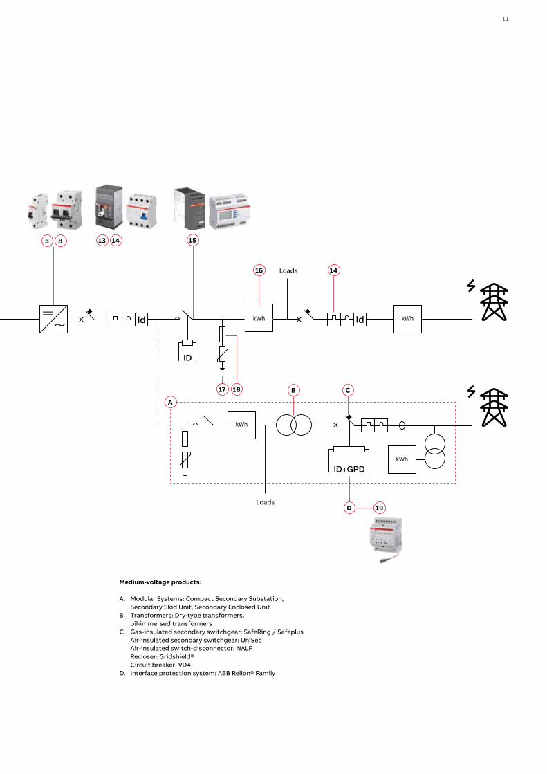
Medium-voltage products:
A. Modular Systems: Compact Secondary Substation, Secondary Skid Unit, Secondary Enclosed Unit B. Transformers: Dry-type transformers, oil-immersed transformersC. Gas-insulated secondary switchgear: SafeRing / Safeplus Air-insulated secondary switchgear: UniSec Air-insulated switch-disconnector: NALF Recloser: Gridshield® Circuit breaker: VD4D. Interface protection system: ABB Relion® Family
11

— Examples of photovoltaic applications Utility scale systems > 1000 kW MV/HVCentral inverters
ID+GPD
ID+GPD
Id
4
1
6
12
A
9
7
7
11
8
358
10
3
32
12 S O LUTI O N S FO R S O L A R E N E RGY
ID+GPD
ID+GPD
Id
15
16
E
1314 B
D
D
C G G
F
To next inverter
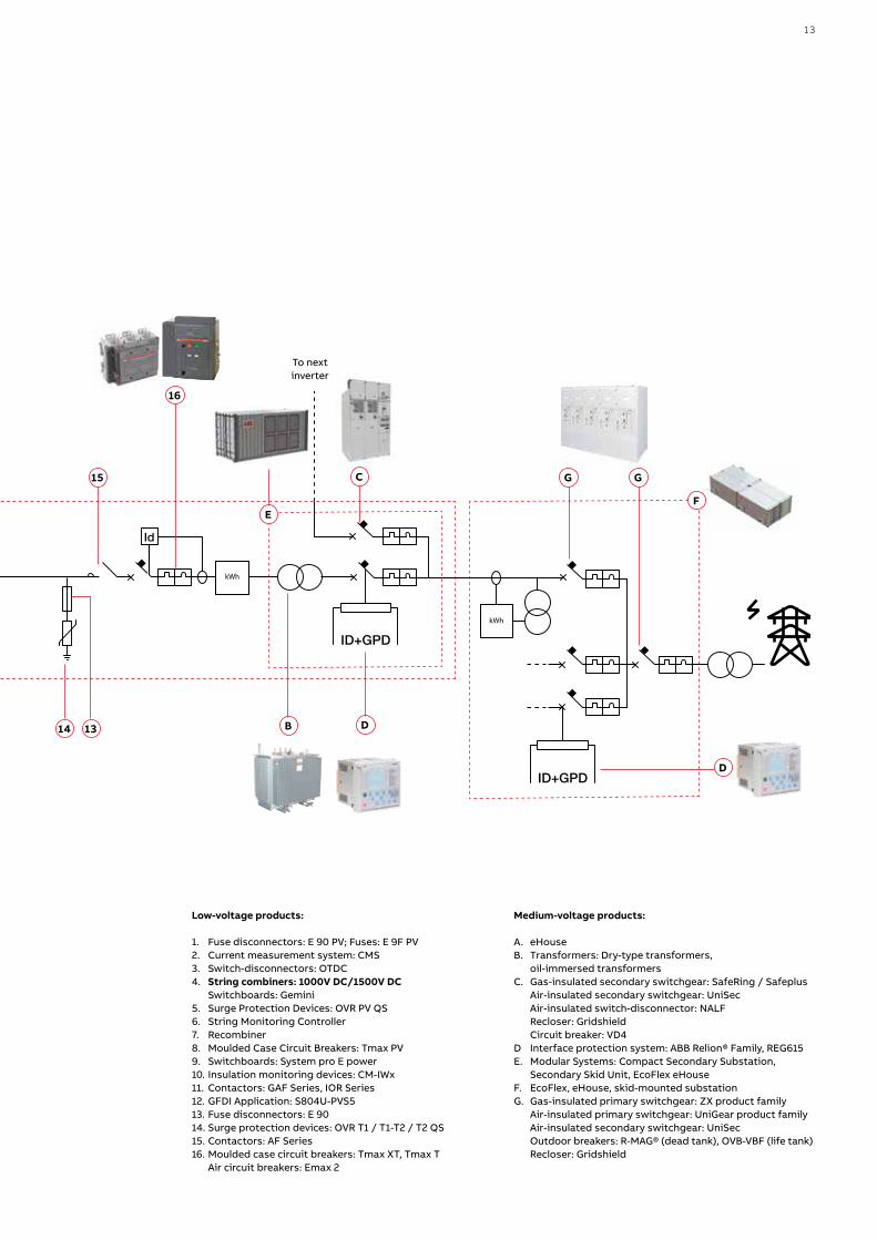
Low-voltage products:
1. Fuse disconnectors: E 90 PV; Fuses: E 9F PV2. Current measurement system: CMS3. Switch-disconnectors: OTDC4. String combiners: 1000V DC/1500V DC Switchboards: Gemini 5. Surge Protection Devices: OVR PV QS6. String Monitoring Controller7. Recombiner8. Moulded Case Circuit Breakers: Tmax PV9. Switchboards: System pro E power10. Insulation monitoring devices: CM-IWx11. Contactors: GAF Series, IOR Series12. GFDI Application: S804U-PVS513. Fuse disconnectors: E 9014. Surge protection devices: OVR T1 / T1-T2 / T2 QS15. Contactors: AF Series16. Moulded case circuit breakers: Tmax XT, Tmax T Air circuit breakers: Emax 2
Medium-voltage products:
A. eHouseB. Transformers: Dry-type transformers, oil-immersed transformersC. Gas-insulated secondary switchgear: SafeRing / Safeplus Air-insulated secondary switchgear: UniSec Air-insulated switch-disconnector: NALF Recloser: Gridshield Circuit breaker: VD4D Interface protection system: ABB Relion® Family, REG615E. Modular Systems: Compact Secondary Substation, Secondary Skid Unit, EcoFlex eHouseF. EcoFlex, eHouse, skid-mounted substationG. Gas-insulated primary switchgear: ZX product family Air-insulated primary switchgear: UniGear product family Air-insulated secondary switchgear: UniSec Outdoor breakers: R-MAG® (dead tank), OVB-VBF (life tank) Recloser: Gridshield
13

ID+GPD
ID+GPD
Id
2
4
6
1
3
5
A
7
11
8 9
— Examples of photovoltaic applications Utility scale systems > 1000 kW MV/HVString inverters
10 12
14 S O LUTI O N S FO R S O L A R E N E RGY

ID+GPD
ID+GPD
Id
15
161314 B D
C F F
E
Low-voltage products:
1. String Combiner2. Molded Case Circuit Breakers Tmax PV (e.g. T4N/PV-E)3. Recombiner4. Molded Case Circuit Breakers for AC applications (e.g. T4V-HA)5. Switchboard6. Molded Case Circuit Breakers for AC applications (e.g. T5V-HA)7. Switchboards: System pro E power8. Moulded Case Circuit Breakers: Tmax PV9. Insulation monitoring devices: CM-IWx10. Contactors: GAF Series, IOR Series rail contactors11. GFDI Application: S804U-PVS512. Switch-disconnectors: OTDC13. Fuse disconnectors: E 9014. Surge protection devices: OVR T1 / T1-T2 / T2 QS15. Contactors: AF Series16. Moulded case circuit breakers: Tmax XT, Tmax T Air circuit breakers: Emax 2
Medium-voltage products:
A. Modular Systems: Compact Secondary Substation, Secondary Skid Unit, EcoFlex eHouseB. Transformers: Dry-type transformers, oil-immersed transformersC. Gas-insulated secondary switchgear: SafeRing / Safeplus Air-insulated secondary switchgear: UniSec Air-insulated switch-disconnector: NALF Recloser: Gridshield Circuit breaker: VD4D Interface protection system: ABB Relion® Family, REG615E. EcoFlex, eHouse, skid-mounted substationF. Gas-insulated primary switchgear: ZX product family Air-insulated primary switchgear: UniGear product family Air-insulated secondary switchgear: UniSec Outdoor breakers: R-MAG® (dead tank), OVB-VBF (life tank) Recloser: Gridshield
D
To next inverter
15
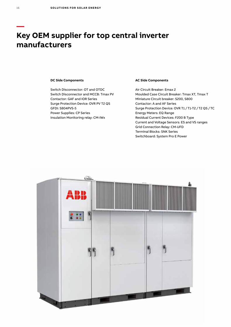
DC Side Components
Switch Disconnector: OT and OTDCSwitch Disconnector and MCCB: Tmax PVContactor: GAF and IOR SeriesSurge Protection Device: OVR PV T2 QSGFDI: S804PVS-5 Power Supplies: CP SeriesInsulation Monitoring relay: CM-IWx
AC Side Components
Air Circuit Breaker: Emax 2Moulded Case Circuit Breaker: Tmax XT, Tmax TMiniature Circuit breaker: S200, S800Contactor: A and AF SeriesSurge Protection Device: OVR T1 / T1-T2 / T2 QS / TCEnergy Meters: EQ RangeResidual Current Devices: F200 B TypeCurrent and Voltage Sensors: ES and VS rangesGrid Connection Relay: CM-UFDTerminal Blocks: SNK SeriesSwitchboard: System Pro E Power
— Key OEM supplier for top central inverter manufacturers
16 S O LUTI O N S FO R S O L A R E N E RGY

DC Side Components
Fuse Disconnector: E90PVSwitch Disconnector: OTDCMiniature Circuit breaker: S200 MU C, S800 PVSurge Protection Device: OVR PV T2 QS
AC Side Components
Switch Disconnector: OTMiniature Circuit breaker: S 200, S800Surge Protection Device: OVR T2 QSContactors: A and AF SeriesEnergy Meter: EQ SeriesTerminal Blocks: SNK Series
— Key OEM supplier for top string inverter manufacturers
17

Switch-disconnectors: Tmax PVSwitch-disconnectors: OTDC seriesMiniature circuit-breakers: S800 PV-SFuse disconnectors: E 90 PV Surge protective devices: OVR PV QSCircuit Measurement System: CMSOutdoor Enclosure: Gemini, Europa SNK terminal blocksWiring ducts
— DC string boxes
18 S O LUTI O N S FO R S O L A R E N E RGY

Power Collection
Modular Systems: Compact SecondarySubstation, Secondary Skid Unit, EcoFlex eHouseGas-insulated secondary switchgear:SafeRing / SafeplusAir-insulated secondary switchgear: UniSecRecloser: GridshieldSwitch-disconnector: NALFRelays: Relion familyFusesService
Grid Connection
Modular Systems: eHouses, skid-mounted substations, EcoFlex eHouseGas-insulated primary switchgear: ZX product familyAir-insulated primary switchgear: UniGearproduct family, UniGear DigitalAir-insulated secondary switchgear: UniSecMedium-voltage circuit breakers: VD4, ADVAC, AMVACOutdoor circuit breakers: R-MAG (dead-tank),OVB-VBF (life-tank)Recloser: GridShieldRelays: ABB Relion, REG615Service
— Medium-voltage (MV) solutions
19

— Product packages for solar plantsMultiple products under one contract
Packaging of multiple products, including interface engineering, provides customers a fully integrated solution under a single commercial agreement. Throughout a project, there may be complications of interfacing with multiple vendors during procurement, engineering and execution, along with challenges to mitigate risk. ABB, as a market leader delivering electrification solutions for project applications, is able to address these by leveraging its comprehensive product portfolio and third party offerings.
On a daily basis, ABB offers a combination of products and services to customers. Product packaging has been developed to further enhance the offering to our customers by providing a seamless integration of multiple product elements.
20 S O LUTI O N S FO R S O L A R E N E RGY
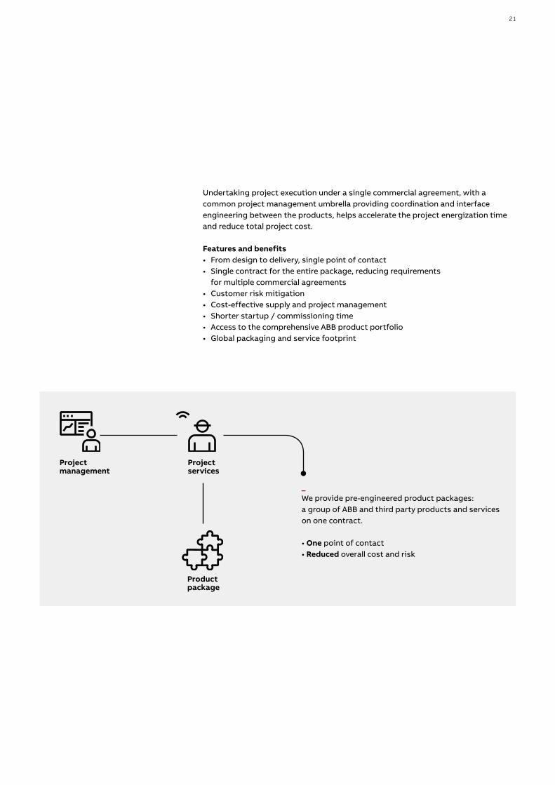
Project management
Project services
Productpackage
Undertaking project execution under a single commercial agreement, with a common project management umbrella providing coordination and interface engineering between the products, helps accelerate the project energization time and reduce total project cost.
Features and benefits• From design to delivery, single point of contact• Single contract for the entire package, reducing requirements
for multiple commercial agreements• Customer risk mitigation• Cost-effective supply and project management• Shorter startup / commissioning time• Access to the comprehensive ABB product portfolio• Global packaging and service footprint
_We provide pre-engineered product packages: a group of ABB and third party products and serviceson one contract.
• One point of contact• Reduced overall cost and risk
21

— Photovoltaic systems Products for DC side
22 S O LUTI O N S FO R S O L A R E N E RGY

23

—Fuse disconnectorsE 90 PV
The E 90 PV series of fuseholders and disconnectors has been designed for 1000V DC and 1500V DC applications. The E 90 PV series is specifically focused on overcurrents protection of photovoltaic systems. It provides a reliable, compact and effective solution in combination with 10,3 x 38 gPV cylindrical fuses (1000V DC applications) or in combination with 10 x 85 and 10/14x85 gPV cylindrical fuses (1500V DC applications). The main features of E 90 PV fuseholders and disconnectors include:• High temperature performance thanks to venting grooves and cooling
chambers that improve heat dissipation also for multipole configurations• IP 20 touch proof ensuring no possibility of getting in touch with live parts
during maintenance operation or fuse replacement, ensuring personnel protection
• In case of E90 PV for 1000V DC applications, safety during maintenance operations can be further ensured by the possibility to seal the handle in close position and lock it in open position
• Faster identification of faulty strings in case of fuse holders for 1000V DC installations; thanks to the LED on the fuse holder which indicates the blown fuse.
Type E90/32 PV E90/32 PV 1500
Reference standards -IEC 60947-3, UL 4248-1,
UL 4248-18IEC 60269-1,-2,-6
UL 4248-19
Rated current A 30 32 (acc. IEC)/ 30 (acc. UL)
Rated operational voltage V 1000V DC 1500V DC
Fuse size mm 10x30 10x85 and 10/14x85
Max power dissipation accepted W 3 6
Tightening torque NmPZ2 2-2.5 Nm
(PZ2 18-22 lb-in)PZ2 2-2.5 Nm
(PZ2 18-22 lb-in)
Protection degree - IP20 IP20
Cross section rigid copper conductors (1 wire) mm2 1.5 - 25 (16-4 AWG)
Cross section stranded copper conductors (1 wire) mm2 1.5 - 16 (16-5 AWG) 0.75 – 25 (18-4 AWG)
Cross section stranded copper conductors (2 wires of same sect.) mm2 0.75 – 10 (18-6 AWG)
Cable temperature °C CU 60, 75, 90 max 90 (acc. UL)
Operating temperature °C -0,125 > -5
Storage temperature °C -0,357142857 > -25
Temperature stability (main body) °C 125
Approvals - UL, CCC, EAC UL
24 S O LUTI O N S FO R S O L A R E N E RGY

—Cylindrical fusesE 9F PV
The E 9F PV series of cylindrical fuses has been specifically designed for protecting direct current circuits up to 1500V.
Available in the 10.3 x 38 mm size for up to 30 A rated current values at a nominal voltage of 1000V DC or in the 10x85 mm size up to 32 A rated current at a nominal voltage of 1500V DC, they are the best way to protect strings, inverters and surge arresters in photovoltaic installations.
Type E9F PV E9F PV 1500
Reference standards -IEC 60269-6; ROHS
2002/98/CE, ULIEC 60269-6; ROHS
2002/98/CE, UL
Rated current A 1..30 4…32
Rated operational voltage V 1000 DC 1500 DC
Breaking capacity kA 10 50
Overall dimensions mm 10.3x38 10x85
25
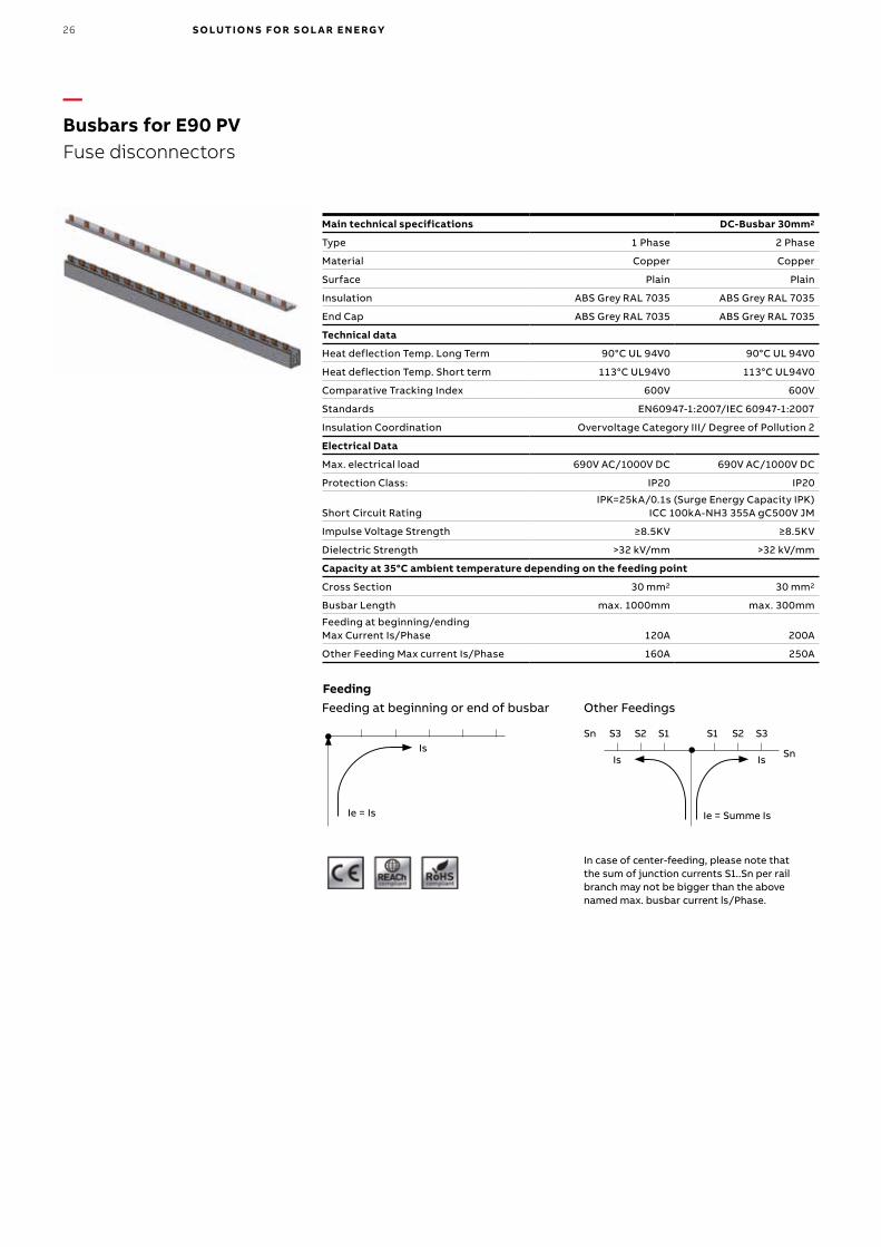
—Busbars for E90 PVFuse disconnectors
Main technical specifications DC-Busbar 30mm2
Type 1 Phase 2 Phase
Material Copper Copper
Surface Plain Plain
Insulation ABS Grey RAL 7035 ABS Grey RAL 7035
End Cap ABS Grey RAL 7035 ABS Grey RAL 7035
Technical data
Heat deflection Temp. Long Term 90°C UL 94V0 90°C UL 94V0
Heat deflection Temp. Short term 113°C UL94V0 113°C UL94V0
Comparative Tracking Index 600V 600V
Standards EN60947-1:2007/IEC 60947-1:2007
Insulation Coordination Overvoltage Category III/ Degree of Pollution 2
Electrical Data
Max. electrical load 690V AC/1000V DC 690V AC/1000V DC
Protection Class: IP20 IP20
Short Circuit RatingIPK=25kA/0.1s (Surge Energy Capacity IPK)
ICC 100kA-NH3 355A gC500V JM
Impulse Voltage Strength ≥8.5KV ≥8.5KV
Dielectric Strength >32 kV/mm >32 kV/mm
Capacity at 35°C ambient temperature depending on the feeding point
Cross Section 30 mm2 30 mm2
Busbar Length max. 1000mm max. 300mm
Feeding at beginning/ending Max Current Is/Phase 120A 200A
Other Feeding Max current Is/Phase 160A 250A
Feeding at beginning or end of busbar Other Feedings
In case of center-feeding, please note that the sum of junction currents S1..Sn per rail branch may not be bigger than the above named max. busbar current ls/Phase.
Is
Ie = Is
Sn
SnIs
Ie = Summe Is
Is
S3 S1S2 S2S1 S3
Feeding
26 S O LUTI O N S FO R S O L A R E N E RGY

—Miniature circuit-breakers S800 PV-SP
1
2
3
4
5
6
7
8
1
2
3
4
800V DC 1500V DCNon-earthed network
1
2
3
4
800V DC 1200V DCEarthed network
1
2
3 5
4 6
Panel network in earth-insulated systems
The S800 PV-SP modular miniature circuit-breakers can be used in networks up to 1500V DC (4-poles execution). The S800 PV-SP circuit breakers and its range of accessories (auxiliary contacts, undervoltage releases, motorized commands) allow for a wide spectrum of configurations.The main features of the S800 PV-SP circuit breakers include:
- interchangeable terminals- central trip safe disconnection of all poles- contact status displayed for each pole- polarity independent wiring
Main technical specifications S800 PV-SP
Reference Standards IEC EN 60947-2 and Annex P
Rated current A 5…125
Number of poles 2 ... 4Rated voltage Ue
(DC) 2 poles* (DC) 3 poles* (DC) 4 poles*
VV V
800 1200 1500
Ultimate rated short-circuit breaking capacity Icu 5…16A acc. IEC 60947-2 Annex P20…125A acc. IEC 60947-2 20…125A acc. IEC 60947-2 Annex P
kA kA kA
553
Thermomagnetic release characteristic 4 In ≤ Im ≤ 7 In
Class of use A
Operating temperature °C -25…+60 Mounting DIN rail EN 60715 (35 mm)
by means of fast clip device
* Please refer to the wiring diagrams
27

—Switch-disconnectors S800 PV-SD, S802 PV-M-H
1
2
3
4
5
6
7
8
1
2
3
4
800V DC 1500V DCNon-earthed network
1
2
3
4
800V DC 1200V DCEarthed network
1
2
3 5
4 6
The S800 PV-SD modular switch-disconnectors can be used in networks up to 1500V DC (4-poles execution). The S800 PV-SD switch-disconnectors and its range of accessories (auxiliary contacts, undervoltage releases, motorized commands) allow for a wide spectrum of configurations.The main features of the S800 PV-SD switch-disconnectors include:
• interchangeable terminals• contact status displayed for each pole• polarity independent wiring
Main technical specifications S800 PV-SD
Reference Standards IEC EN 60947-3 and Annex D
Rated current In A 32, 63, 125
Number of poles 2…4
Rated voltage Ue(DC) 2 poles* (DC) 3 poles* (DC) 4 poles*
VV V
8001200 1500
Rated short-time withstand current Icw (DC) 2 poles* 800 V(DC) 3 poles* 1200 V(DC) 4 poles* 1500 V
kA kA kA
1.51.51.5
Class of use DC-21A , DC-PV2
Operating temperature °C -25…+60
Mountingon DIN rail EN 60715 (35 mm)
by means of fast clip device
* Please refer to the wiring diagrams
The S802 PV-M-H polarized switch-disconnectors are specially designed for networks up to 1000V DC. They are equipped with permanent magnets which provide the switch polarity, therefore a correct supply voltage is required. S802 PV-M-H switch-disconnectors and its range of accessories (auxiliary contacts, undervoltage releases, motorized commands) allow for a wide spectrum of configurations.The main features of the S802 PV-M-H switch-disconnectors include:
• interchangeable terminals• contact status displayed for each pole
Main technical specifications S802 PV-M-H
Reference Standards IEC EN 60947-3
Rated current In A 32, 63, 100
Number of poles 2
Rated voltage Ue (DC) 2 poles* V 1000
Rated short-time withstand current Icw (DC) 2 poles* 1000 V kA 1.5
Class of use DC-21A
Operating temperature °C -25…+60
Mountingon DIN rail EN 60715 (35 mm)
by means of fast clip device
* Please refer to the wiring diagrams
1
2
3
4
L –
– +
L +
1
2
3
4
+ –
L + L –
S802 PV-M-H
Comply with polarity and supply direction in wiring.
28 S O LUTI O N S FO R S O L A R E N E RGY

Function: string protection.The S804U-PVS5 is for string protection in photovoltaic systems.In case of reverse currents, the breaker wil trip. Thus the PV generator will not be damaged. The breaker is tested acc. to UL489B for 1000V DC.
Main technical specifications S804U-PVS5
Reference Standards UL489B (Photovoltaic)
Poles 4
Tripping characteristics PVS
Rated current Ie A 5
Rated frequency f Hz -Rated insulation voltage Ui acc. to IEC/EN 60664-1 V DC 1500Rated impulse withstand voltage Uimp. (1.2/50μs) kV 8
Overvoltage category IV
Pollution degree 3
Suitability for isolation yes
Data acc. to UL / CSA
Rated voltage V DC 1000
Rated interrupting capacity acc. to UL 1077 kA
Short-circuit current rating acc. to UL 489 kA
Short-circuit current rating acc. to UL 489B kA 1.5kA
Application GFDI in PV-applicatoinReference temperature for tripping characteristics °C 50°CElectrical and Mechanical endurance
ops.acc. to UL489B 1000 with current; 1000
without current
Mechanical Data
Housing Material group I, RAL 7035
Toggle black, lockable
Ambient temperature °C -25… + 60
Storage temperature °C -40 … +70
—Switch-disconnectors S804U-PVS5
29

The pole connector S802-LINK125 is for currents up to 125A. The black cooling elements help to avoid overheating.
What has to be secured in PV-application?• Simultaneity factor is 1 in photovoltaic• Ambient temperature of devices must be observed• Calculation of internal resistance of all devices in an enclosure due to dimension
of enclosure• Pole connection must be observed• Terminal temperature must be maintained in accordance with IEC 61439•1• Dimensioning of enclosure (power losses of all devices / heating)• Assembly area of enclosure (no directly sun radiation)• Mounting distances between each device• ABB recommend to perform temperature rise tests
Advantages of the pole connector:• Avoid hazardous situation due to high temperatures in demanding applications• Avoid early tripping of the MCB• Reduce heat dissipation of the MCBs in the box with significant temperature reduction• Rated current range of 50A and 125A used in 2 pole and 4 pole breakers• Avoid isolation damage by excessive bent of the cable (not following cable manufacturer limits)
—S800PV-SP
Ie [A] 10°C 15°C 20°C 25°C 30°C 35°C 40°C 45°C 50°C 55°C 60°C
10 11 11 11 10 10 10 9 9 9 8 8
13 15 14 14 13 13 12 12 12 11 11 10
16 18 18 17 17 16 15 15 14 14 13 13
20 22 22 21 21 20 19 19 18 17 17 16
25 28 28 27 26 25 24 23 23 22 21 20
32 36 35 34 33 32 31 30 39 28 27 26
40 45 44 43 42 40 38 37 36 35 33 32
50 56 55 54 52 50 48 47 45 45 43 40
63 71 69 67 66 63 61 59 57 57 54 50
80 90 88 86 83 80 77 74 72 72 68 64
100 112 110 107 104 100 96 93 90 90 85 80
125 140 137 134 130 125 120 100 94 88 81 75
—S800PV-SD
Ie [A] 10°C 15°C 20°C 25°C 30°C 35°C 40°C 45°C 50°C 55°C 60°C
32 32 32 32 32 32 32 32 32 32 32 32
63 63 63 63 63 63 63 63 63 63 63 63
125 125 125 125 125 125 125 100 100 100 100 100
These value apply in combination with pole connector S802-LINK50
The tables are based on measurements using cable as stated in IEC 60947-2. Any deviation from these cable diameters and lengths might lead to higher temperatures. Therefore ABB recommends to perform temperature measurements to verify the real maximum temperature in the application.
—Pole connector S802-LINK125
30 S O LUTI O N S FO R S O L A R E N E RGY

The DBL distribution blocks are adapted to the most recent solar inverters requirements with a voltage rating going up to 1500V DC IEC (1000V DC UL). They provide the benefit of 3 configurations in 1 single product: grouping several inputs into one output for DC applications, or single and multipole splitting for AC power applications.
The reversible cover facilitates identification and wiring tasks, and the modular and touch proof design eliminates the need for bus bars, isolators, fasteners or protection screens.
Finally it saves up to 50% rail space compared to conventional distribution bars.
Main technical specifications DBL
Section Number of inputs Rated voltage
16 mm2 4 AWG 80A 7 1500V DC (IEC) 1000V DC (UL) DBL80
35 mm2 2 AWG 125A 8 DBL125
50 mm2 2/0 AWG 160A 8 DBL160
175A 12 DBL175
95 mm2 250 Kcmil 250A 12 DBL250
150 mm2 400 Kcmil 400A 12 DBL400
String combinerPV module
RoHS
—Distribution blocksDBL
31

Inverter
String
Combiner
Sensors - Mounting type System pro M DIN rail Cable Ties
AC accuracy≤±1.0% The Laying Method Influences the accuracy
For fuse holders E90 1000V DC
universal use universal use
18mm CMS-120xx (80 A)CMS-121xx (40 A)CMS-122xx (20 A)
CMS-121FHCMS-122FH
CMS-120DRCMS-121DRCMS-122DR
CMS-120CACMS-121CACMS-122CA
The CMS string monitoring increases the efficiency of your photovoltaic system. The easy-to-integrate system enables you to immediately The CMS string monitoring increases the efficiency of your photovoltaic system.The easy-to-integrate system enables you to immediately detect unusual system status, like e.g. defective strings, overvoltages, breaker trips or high temperatures. Main use is for string monitoring in combiner boxes to detect failures on PV strings and quickly implement appropriate countermeasures.
Main benefits: • minimum space requirements• up-to-date system status at any time• simplified installation and quick commissioning • high flexibility on the number of measurement points
Control Unit - Main technical specification CMS-660
Max. number of CMS sensors 32
Supply voltage V DC 24 (± 10 %)
Communication protocol Modbus RTU (RS485 2 wire)
Digital inputs 2
Operating temperature °C -25 .. +70
Dimensions mm 71.8 x 87.0 x 64.9 (4 DIN modules)
Sensors - Main technical specifications CMS-120xx CMS-121xx CMS-122xx
Measurement range A 80 40 20
Measuring method TRMS, AC 50/60 Hz, DC
Peak factor, distorted waveform ≤ 1.5 ≤ 3 ≤ 6
AC accuracy (TA = + 25 °C) ≤ ± 1 %
AC temperature coefficient ≤ ± 0,04 %
DC accuracy (TA = + 25 °C) ≤ ± 1.2 % ≤ ± 1.4 % ≤ ± 1.8 %
DC temperature coefficient ≤ ± 0.14 % ≤ ± 0.24 % ≤ ± 0.44 %
Resolution A 0.01
Sampling rate, internal Hz 5000
Response time (±1 %) sec typ. 0.34
Max. cable diameter mm 9,6
Insulation strength V 690V AC/1500V DC
Dimensions
CMS-120FH mm 17.4x41.0x38.9
CMS-120CA Serie mm 17.4x41.0x29.0
CMS-120DR Serie mm 17.4x51.5x43.2
—String monitoring Circuit Measurement System (CMS)
32 S O LUTI O N S FO R S O L A R E N E RGY

—Insulation monitoring devices ISL-A 600, ISL-C 600
In IT electrical distribution networks with isolated neutral, and in PV networks particularly, the high insulation impedance prevents earth faults from generating currents that would dangerously elevate the potential of exposed conductive parts. Therefore, in case of earth leakage, in an IT network it is not necessary to interrupt the supply, but it is still essential to monitor the insulation level in order to detect faults and restore optimal functioning of the system.The ISL-C 600 is a insulation monitoring device for IT distribution networks up to 760V AC (1100V AC in three phase networks with neutral). The ISL-A 600 version is an insulation monitoring device for DC IT networks up to 600V DC.
Main technical specifications ISL-A 600 ISL-C 600
For PV applications
For PV applications
Power consumption VA 6 5
ALARM threshold kΩ 30÷300 -
TRIP threshold kΩ 30÷300 10÷100
Max measuring current mA 1.5 0.240
Max measuring voltage V DC - 48
Internal Impedance kΩ880 kΩ L+/L-
450 kΩ L/Ground 200
TRIP relay output (NO-C-NC) 1 2
ALARM relay output (NO-C-NC) 2 -
Relay contact capacity 250 V 5 A 250 V 5 A
Operating temperature °C -10 ÷ 60 -10 ÷ 60
Storage temperature °C -20 ÷ 70 -20 ÷ 70
Relative humidity ≤ 95% ≤ 95%
Max terminal section mm2 2.5 2.5
IP class IP40 front, IP20 case
Modules 6 6
Weight g 400 500
Reference standards
EN 61010-1,EN 61557-8,EN 61326-1
EN 61010-1,EN 61557-8,EN 61326-1
33

OTDC16...32 disconnect switches are available up to 32 amperes and 1000V DC. The modular structure offers a simple and cost effective solution for disconnecting up 1, 2, or 3 PV circuits within the same footprint area.
The main features of the OTDC16...32 disconnect switches include• Patented design of DC main contacts offer: - Low temperature rise for minimal contribution to overall heat-rise within any enclosure. - High operational performance, 32A up to 1000V, in high ambient temperatures. - Increased energy efficiency• Compactness and modularity: allow for consistent and optimized mounting in
switchboard equipment, therefore reducing implementation costs and increased space savings.
• DINrail, base, or door-mounted versions for simple installation in a variety of enclosure designs.
• Compliant with many global standards, including UL 508i.• OTDC16...32US versions are factory pre-connected for single-wire breaking
applications.• Enclosed OTDCP16...32 versions are suitable for outdoor use in harsh
environments.
OTDC16..32F
OTDCP16...32F
OTDC16....32U
—Switch-disconnectors OTDC16...32
34 S O LUTI O N S FO R S O L A R E N E RGY
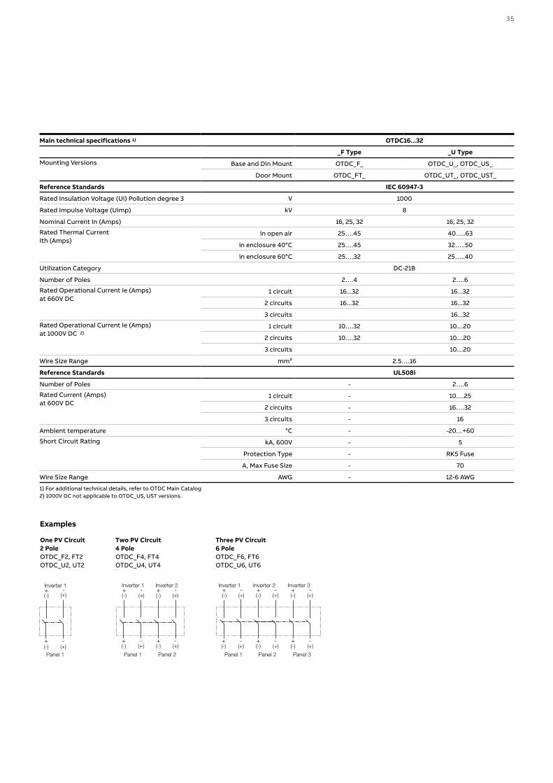
Examples
One PV Circuit2 PoleOTDC_F2, FT2OTDC_U2, UT2
+ -(-) (+)Panel 1
+(-)
Inverter 1-
(+)
+ -(-) (+)
Panel 1
+ -(-) (+)
Panel 2
+(-)
Inverter 1-
(+)+(-)
Inverter 2-
(+)
+ -(-) (+)
Panel 1
+ -(-) (+)
Panel 2
+(-)
Inverter 1-
(+)+(-)
Inverter 2-
(+)
+ -(-) (+)
Panel 3
+(-)
Inverter 3-
(+)
Two PV Circuit4 PoleOTDC_F4, FT4OTDC_U4, UT4
+ -(-) (+)Panel 1
+(-)
Inverter 1-
(+)
+ -(-) (+)
Panel 1
+ -(-) (+)
Panel 2
+(-)
Inverter 1-
(+)+(-)
Inverter 2-
(+)
+ -(-) (+)
Panel 1
+ -(-) (+)
Panel 2
+(-)
Inverter 1-
(+)+(-)
Inverter 2-
(+)
+ -(-) (+)
Panel 3
+(-)
Inverter 3-
(+)
Three PV Circuit6 PoleOTDC_F6, FT6OTDC_U6, UT6
+ -(-) (+)Panel 1
+(-)
Inverter 1-
(+)
+ -(-) (+)
Panel 1
+ -(-) (+)
Panel 2
+(-)
Inverter 1-
(+)+(-)
Inverter 2-
(+)
+ -(-) (+)
Panel 1
+ -(-) (+)
Panel 2
+(-)
Inverter 1-
(+)+(-)
Inverter 2-
(+)
+ -(-) (+)
Panel 3
+(-)
Inverter 3-
(+)
Main technical specifications 1) OTDC16...32
_F Type _U Type
Mounting Versions Base and Din Mount OTDC_F_ OTDC_U_, OTDC_US_
Door Mount OTDC_FT_ OTDC_UT_, OTDC_UST_
Reference Standards IEC 60947-3
Rated Insulation Voltage (Ui) Pollution degree 3 V 1000
Rated Impulse Voltage (Uimp) kV 8
Nominal Current In (Amps) 16, 25, 32 16, 25, 32
Rated Thermal Current Ith (Amps)
in open air 25….45 40…..63
in enclosure 40°C 25….45 32…..50
in enclosure 60°C 25….32 25…..40
Utilization Category DC-21B
Number of Poles 2….4 2….6
Rated Operational Current Ie (Amps) at 660V DC
1 circuit 16...32 16...32
2 circuits 16...32 16...32
3 circuits 16...32
Rated Operational Current Ie (Amps) at 1000V DC 2)
1 circuit 10….32 10....20
2 circuits 10….32 10....20
3 circuits 10....20
Wire Size Range mm² 2.5….16
Reference Standards UL508i
Number of Poles - 2….6
Rated Current (Amps) at 600V DC
1 circuit - 10….25
2 circuits - 16….32
3 circuits - 16
Ambient temperature °C - -20…+60
Short Circuit Rating kA, 600V - 5
Protection Type - RK5 Fuse
A, Max Fuse Size - 70
Wire Size Range AWG - 12-6 AWG
1) For additional technical details, refer to OTDC Main Catalog2) 1000V DC not applicable to OTDC_US, UST versions.
35

The OTDC series of switch-disconnectors is available with nominal currents from 100 to 1600 A. OTDC 100...800: Two poles in series provides compact performance up to 1000V DC. Up to three 1000 V circuits can be operated with a single device. It is also possible to use the switch as a combiner, with separate inputs and a combined output of up to 1500A.OTDC1000...1600: Four poles in series provides compact performace up to 1000V DC for use in high power applications. The main features of the OTDC100…1600 switch-disconnectors include:• Compactness: thanks to the patented DMB (Dual Magnetic Breaking) technology,
the switches reach 1000V DC with two poles in series for most sizes.• Easy to install: connections are simple and independent from polarity, for
providing greater wiring flexibility. The operating mechanism can be located between the poles or on the left side of the switch.
• Factory-installed or jumper kits available.• Safety: Visible contacts allow a clear indication of position.
—Switch-disconnectors 1000V DC and up to 1600A: OTDC100...1600
36 S O LUTI O N S FO R S O L A R E N E RGY
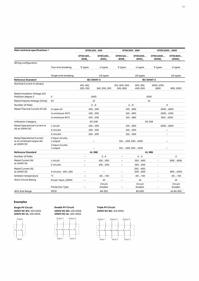
Single PV Circuit1000V DC IEC: 100-500A1000V DC UL: 100-400A
Examples
+ -Input
+Output
-
+ -Input 1
+ -Input 2
+Output 1
- +Output 2
-
+ -Input 1
+ -Input 2
+Output 1
- +Output 2
-
+ -Input 3
+Output 3
-
Double PV Circuit1000V DC IEC: 100-500A1000V DC UL: 100–400A
+ -Input
+Output
-
+ -Input 1
+ -Input 2
+Output 1
- +Output 2
-
+ -Input 1
+ -Input 2
+Output 1
- +Output 2
-
+ -Input 3
+Output 3
-
Triple PV Circuit1000V DC IEC: 315-500A
+ -Input
+Output
-
+ -Input 1
+ -Input 2
+Output 1
- +Output 2
-
+ -Input 1
+ -Input 2
+Output 1
- +Output 2
-
+ -Input 3
+Output 3
-
Main technical specifications 1) OTDC100…250 OTDC250…800 OTDC1000…1600
OTDC100…250E_
OTDC100…200U_
OTDC315…800E_
OTDC250…600U_
OTDC1000…1600E_
OTDC800…1000U_
Wiring configuration
Two-wire breaking E types U types E types U types E types U types
Single-wire breaking US types US types US types
Reference Standard IEC 60947-3 IEC 60947-3
Nominal Current In (Amps)100, 160, 200, 250 160, 200, 250
315, 400, 500, 630, 800
250, 320, 400, 600
1000, 1250, 1600 800, 1000
Rated Insulation Voltage (Ui)Pollution degree 3 V 1000 1500
Rated Impulse Voltage (Uimp) kV 12 12
Number of Poles 2…6 2…6 4
Rated Thermal Current Ith (A) in open air 100…250 315…800 1000…1600
in enclosure 40°C 100…250 315…800 1000…1250
in enclosure 60°C 100…200 315…680 800…1000
Utilization Category DC-21B DC-21B
Rated Operational Current Ie (A) at 1000V DC
1 circuit 100…250 315…800 1000…1600
2 circuits 100…250 315…500 –
3 circuits 100…200 315…500 –
Rated Operational Current Ie of combined output (A) at 1000V DC
2 input circuits, 1 output – 315….500, 630…1000 –
3 input circuits, 1 output – 315….500, 945…1500 –
Reference Standard UL 98B UL 98B
Number of Poles – 2...4 – 2…4 - 4
Rated Current (A) at 1000V DC
1 circuit – 100…200 – 250…600 - 800…1000
2 circuits – 100…200 – 250…400 - -
Rated Current (A) at 1000V DC 3 circuits - 100...200 – – –
250…400, 500…800 - 800…1000
Ambient temperature °C – -20…+50 – -20…+50 - -20…+50
Short Circuit Rating kA per input, 1000V – 10 – 10 - 10
Protection Type –Circuit breaker –
Circuit breaker -
Circuit breaker
Wire Size Range MCM #4-300 #2-600 4x #4-300
37

—Switch-disconnectors 1500V DC and up to 500A: OTDC250...500
The OTDC series of switch-disconnectors is also available for operating voltages up to 1500V DC from 100A to 500A. OTDC250..500 switch-disconnectors can operate up to two separate 1500V DC circuits with a single device.
The main features of the OTDC100…500 switch-disconnectors include:• Compactness: thanks to the patented DMB (Dual Magnetic Breaking) technology,
the switches reach 1500V DC with a small footprint and with 3 poles in a most of sizes.
• Easy to install: connections are simple and independent from polarity, for providing greater wiring flexibility.
• Factory-installed or jumper kits available.• Safety: Visible contacts allow a clear indication of position.
Main technical specifications OTDC100…200
1500V DC basic versions OTDC100...200EV_ OTDC100...200UV_
Wiring configuration Two-wire breaking E types U types
Single-wire breaking US types
Reference Standard IEC 60947-3
Nominal Current In (Amps) 100, 200
Rated Insulation Voltage (Ui)1500
Pollution degree 3
Rated Impulse Voltage (Uimp) kV 12
Rated Thermal Current Ith (Amps) in open air 100...200
in enclosure 40°C 100…200
in enclosure 60°C 100…200
Number of Poles 4 -
Utilization Category DC-21B
Rated Operational Current Ie (Amps) at 1500V DC One circuit 100…200
Reference Standard UL 98B
Number of Poles 4
Rated Current (Amps) at 1500V DC One circuit - 100…200
Ambient temperature °C - -20+50
Short Circuit Rating kA, 1500V - 10
Protection Type - Circuit breaker
Wire Size Range MCM - - #250-500
Single PV Circuit1500V DC IEC: 100-200A1500V DC UL: 100-200AUngrounded and Grounded System
Examples
-(+)+(-)
42 86
31 75
LOAD -(+)+(-)
42 86
31 75
LOAD-(+)+(-)
42 86
31 75
LOAD
Single circuitE and U types
Single circuitE types
Single circuitUS types
38 S O LUTI O N S FO R S O L A R E N E RGY
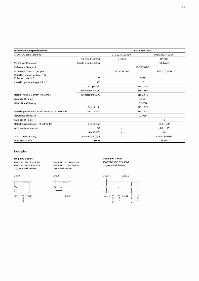
Main technical specifications OTDC250…500
1500V DC basic versions OTDC315...500EV_ OTDC250...400UV_
Wiring configuration
Two-wire breaking E types U types
Single-wire breaking US types
Reference Standard IEC 60947-3
Nominal Current In (Amps) 315, 400, 500 250, 320, 400
Rated Insulation Voltage (Ui)Pollution degree 3 V 1500
Rated Impulse Voltage (Uimp) kV 12
Rated Thermal Current Ith (Amps)
in open air 315…630
in enclosure 40°C 315…550
in enclosure 60°C 315…440
Number of Poles 3…6
Utilization Category DC-21B
Rated Operational Current Ie (Amps) at 1500V DC
One circuit 315…500
Two circuits 315…500
Reference Standard UL 98B
Number of Poles - 3
Rated Current (Amps) at 1500V DC One circuit - 250…400
Ambient temperature °C - -20…+50
Short Circuit Rating
kA, 1500V - 10
Protection Type - Circuit breaker
Wire Size Range MCM - #2-600
Single PV Circuit1500V DC IEC: 315-500A1500V DC UL: 250-400AUngrounded System
1500V DC IEC: 315-500A1500V DC UL: 250-400AGrounded System
Examples
- +Input 1
+Input 1
Out
put 1
Out
put 1
-Output 1
- +Input 1
+ -
Inpu
t 1
Out
put 2
Inpu
t 2
-Output 1
-
+ +Input 2
Output 2
+Input 1
+Output 1
- +Input 1
+Input 1
Out
put 1
Out
put 1
-Output 1
- +Input 1
+ -
Inpu
t 1
Out
put 2
Inpu
t 2
-Output 1
-
+ +Input 2
Output 2
+Input 1
+Output 1
Double PV Circuit1500V DC IEC: 315-500AUngrounded System
- +Input 1
+Input 1
Out
put 1
Out
put 1
-Output 1
- +Input 1
+ -
Inpu
t 1
Out
put 2
Inpu
t 2
-Output 1
-
+ +Input 2
Output 2
+Input 1
+Output 1
39

In accordance with IEC 60947-3, Tmax PV IEC range offers switch-disconnectors to meet standard 1100V DC applications. In addition, it offers the versatility of extended capacities up to 1500V DC. Connection jumpers are an available option for the Tmax PV IEC switch-disconnectors to increase safety and ease of installation. Tmax PV IEC automatic circuit-breakers up to 1000V DC are available as a special version of the standard Tmax T line. Moreover, new Tmax PV IEC automatic circuit- breakers have been developed in accordance to IEC 60947-2 in order to protect the plant up to 1500V DC. In accordance with UL 489B, Tmax PV UL range offers adaptability in the form of the availability of both switch-disconnectors and molded case circuit-breakers. Multiple formats allows for the ability of a uniform end product and shared accessories. ABB offers connection jumpers as a mandatory accessory to Tmax PV UL. The jumpers provide simple, safe use and ensured compliance to new UL regulations. In addition, Tmax PV UL offers the versatility of extended capacities of switch-disconnectors up to 1500V DC.
The main features of the Tmax PV line include:• up to 1500V DC rated voltage • complete offer for a large range of current and voltage• compliant with the most important standard, IEC 60947-3 and UL489B• availability of the three and four poles in fixed versions• suitable for use in extreme condition thanks to operating temperature from
-25°C up to 70 °C.
—Molded case switch-disconnectors up to 1100V DC in compliance with IEC 60947-3
Main technical specifications T1D/PV T3D/PV T4D/PV T5D/PV T6D/PV T7D/PV 1)
Rated service current in category DC22 B, Ie (A) 160 200 250 500 800 1250-1600
Number of poles (No.) 4 4 4 4 4 4
Rated service voltage, Ue 1100V DC 1100V DC 1100V DC 1100V DC 1100V DC 1100V DC
Rated impulse withstand voltage, Uimp (kV) 8 8 8 8 8 8
Rated insulation voltage, Ui (V) 1150V DC 1150V DC 1150V DC 1150V DC 1150V DC 1150V DC
Test voltage at industrial frequency for 1 minute (V) 3500 3500 3500 3500 3500 3500
Rated short-circuit making capacity, switch-disconnector only, Icm (kA) 1.92 2.4 3 6 9.6 19.2
Rated short-time withstand current for 1s, Icw (kA) 1.92 2.4 3 6 9.6 19.2
Versions F F F F F F
Standard terminals FC Cu FC Cu F F F F
Mechanical life (No. Operations) 15000 15000 7500 7500 7500 20000
Electrical life (operations @ 1100V DC) (No. Operations) 500 500 500* 500* 500* 500*
Basic dimensions W (mm/in) 102/4.02 140/5.52 140/5.52 186/7.33 280/11.02 280/11.02
D (mm/in) 70/2.76 70/2.76 103.5/4.07 103.5/4.07 103.5/4.07154/6.06 (manual)
178/7.01 (motorized)
H (mm/in) 130/5.12 150/5.91 205/8.07 205/8.07 268/10.55 268/10.55
Weight (with standard terminals only) (kg/lbs) 1.2/2.65 2/4.41 3.05/6.72 4.15/9.15 12/26.4612.5/27.56 (manual)
14/30.86 (motorized)
1) installation in vertical position only* openings with SOR or UVR
—Switch-disconnectorsTmax PV
40 S O LUTI O N S FO R S O L A R E N E RGY

— Molded case switch-disconnectors up to 1500V DC in compliance with IEC 60947-3
Main technical specifications T4D/PV-E T5D/PV-E T7D/PV-E 1)
Rated service current in category DC22 A, Ie (A) 250 500 1250-1600
Number of poles (No.) 4 4 4
Rated service voltage, Ue 1500V DC 1500V DC 1500V DC
Rated impulse withstand voltage, Uimp (kV) 8 8 8
Rated insulation voltage, Ui (V) 1500V DC 1500V DC 1500V DC
Test voltage at industrial frequency for 1 minute (V) 3500 3500 3500
Rated short-circuit making capacity, switch-disconnector only, Icm (kA) 3 6 19.2
Rated short-time withstand current for 1s, Icw (kA) 3 6 19.2
Versions F F F
Standard terminals F F F
Mechanical life (No. Operations) 7500 7500 20000
Electrical life (operations @ 1500V DC) (No. Operations) 1000* 1000* 500*
Basic dimensions W (mm/in) 140/5.52 186/7.33 280/11.02
D (mm/in) 103.5/4.07 103.5/4.07 178/7.01
H (mm/in) 205/8,07 205/8.07 268/10.55
Weight (with standard terminals only) (kg/lbs) 3.05/6.72 3.15/9.15 14/30.86
1) installation in vertical position only * openings with SOR or UVR
— Molded case switch-disconnectors up to 1500V DC in compliance with UL 489B
Main technical specifications T1N-D/PV T4N-D/PV T5N-D/PV T6N-D/PV T7N-D/PV 1) T7N-D/PV-E 1)
Rated service current (A) 100 200 400 600-800 1000 1000-1200
Number of poles (No.) 4 3 3 4 4 4
Rated service voltage (V) 1000V DC 1000V DC 1000V DC 1000V DC 1000V DC 1500V DC
Short-circuit current withstand (kA) 1.2 3 5 10 18 18
Magentic override (kA) - 3 5 10 - -
Versions F F F F F F
Connections* Jumpers Jumpers Jumpers Jumpers Jumpers Jumpers
Terminals provided with Jumper kit FCCu FCCuAl FCCu-ES FCCuAl-EF FCCuAl-F1000A: F / FCCuAl
1200A: EF
Mechanical life (No. Operations) 15000 7500 7500 7500 20000 20000
Electrical life (operations @ 1000V DC) (No. Operations) 1000 1000** 500** 500** 500** 400**
Basic dimensions W (mm/in) 102/4.02 105/4.13 140/5.52 280/11.02 280/11.02 280/11.02
D (mm/in) 70/2.76 103.5/4.07 103.5/4.07 103.5/4.07 178/7.01 178/7.01
H (mm/in) 130/5.12 205/8.07 205/8.07 268/10.55 268/10.55 268/10.55
Weight (with standard terminals only) (kg/lbs) 1.2/2.65 2.35/5.18 3.25/7.17 12/26.46 14/30.86 14/30.86
1) installation in vertical position only* Selection of one of the jumper connection options is mandatory for Tmax PV UL** openings with SOR or UVR
41

—Automatic Molded Case Circuit BreakersTmax PV
— Molded case circuit-breakers up to 1500V DC in compliance with IEC 60947-2
Main technical specifications T4N-PV/E
Frame size (A) 250
Rated service current (A) 100-250
Number of poles (No.) 4
Rated sevice voltage, Ue (V) 1500
Rated impulse withstand voltage, Uimp (kV) 8
Rated insulation voltage, Ui (V) 1500
Rated ultimate short-circuit breaking capacity @ 1500V DC, Icu (kA) 25 according to IEC 60947-2 Annex P (time constant = 1 ms)
(kA) 10 (time constant = 5 ms)
Rated service short-circuit breaking capacity @ 1500V DC, Ics (kA) 20 according to IEC 60947-2 Annex P (time constant = 1 ms)
(kA) 5 (time constant = 5 ms) - To be confirmed
Trip Unit TMF
Versions F
Terminals F - FCCu -FCCuAl
Connections* Jumpers
Mechanical life with Motor (No. Operations) 7500
Electrical life (operations @ 1000V DC) (No. Operations) 1000**
Basic dimensions W (mm/in) 140/5.52
D (mm/in) 103.5/4.07
H (mm/in) 205/8.07
Weight (with standard terminals only) (kg/lbs) 3.05/6.72
* Selection of one of the jumper connection options is mandatory ** openings with SOR or UVR
Whenever a consistent short-circuit current can be found, 1000V and 1500V DC automatic circuit-breakers are available in the Tmax PV range. Below is the IEC60947-2 automatic circuit-breaker offering at 1500V.
42 S O LUTI O N S FO R S O L A R E N E RGY

Whenever a consistent short-circuit current can be found (like in recombiner boxes), 1000V DC automatic circuit-breakers are available in the Tmax PV range. Below is the UL489B automatic circuit-breakers offering.
— Molded case circuit-breakers up to 1000V DC in compliance with UL 489B
Main technical specifications T4N/PV T5N/PV T6N/PV
Frame size (A) 200 400 600-800
Rated service current (A) 40-200 225-400 600-800
Number of poles (No.) 3 3 4
Rated service voltage (V) 1000V DC 1000V DC 1000V DC
Short-circuit interrupting rating @ 1000V DC (kA) 7.5 5 10
Trip Unit TMD/TMA TMF/TMA TMA
Versions F F F
Standard terminals F F F
Connections* Jumpers Jumpers Jumpers
Terminals provided with Jumper kit FCCuAl FCCuAl-FCCu-ES FCCuAl-EF
Mechanical life (No. Operations) 7500 7500 7500
Electrical life (operations @ 1000V DC) (No. Operations) 1000** 500** 500**
Basic dimensions W (mm/in) 105/4.13 140/5.52 280/11.02
D (mm/in) 103.5/4.07 103.5/4.07 103.5/4.07
H (mm/in) 205/8.07 205/8.07 268/10.55
Weight (with standard terminals only) (kg/lbs) 2.35/5.18 3.25/7.17 12/26.46
* Selection of one of the jumper connection options is mandatory for Tmax PV UL** openings with SOR or UVR
43
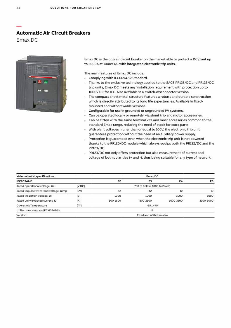
Emax DC is the only air circuit breaker on the market able to protect a DC plant up to 5000A at 1000V DC with integrated electronic trip units.
The main features of Emax DC include: • Complying with IEC60947-2 Standard.• Thanks to the exclusive technology applied to the SACE PR123/DC and PR122/DC
trip units, Emax DC meets any installation requirement with protection up to 1000V DC for IEC. Also available in a switch-disconnector version.
• The compact sheet metal structure features a robust and durable construction which is directly attributed to its long life expectancies. Available in fixed-mounted and withdrawable versions.
• Configurable for use in grounded or ungrounded PV systems.• Can be operated locally or remotely, via shunt trip and motor accessories.• Can be fitted with the same terminal kits and most accessories common to the
standard Emax range, reducing the need of stock for extra parts. • With plant voltages higher than or equal to 100V, the electronic trip unit
guarantees protection without the need of an auxiliary power supply.• Protection is guaranteed even when the electronic trip unit is not powered
thanks to the PR120/DC module which always equips both the PR122/DC and the PR123/DC.
• PR123/DC not only offers protection but also measurement of current and voltage of both polarities (+ and -), thus being suitable for any type of network.
Main technical specifications Emax DC
IEC60947-2 E2 E3 E4 E6
Rated operational voltage, Ue [V DC] 750 (3 Poles), 1000 (4 Poles)
Rated impulse withstand voltage, Uimp [kV] 12 12 12 12
Rated insulation voltage, Ui [V] 1000 1000 1000 1000
Rated uninterrupted current, Iu [A] 800-1600 800-2500 1600-3200 3200-5000
Operating Temperature [°C] -25...+70
Utilization category (IEC 60947-2) B
Version Fixed and Withdrawable
—Automatic Air Circuit BreakersEmax DC
44 S O LUTI O N S FO R S O L A R E N E RGY
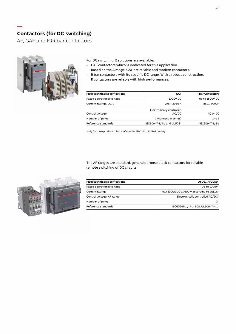
—Contactors (for DC switching) AF, GAF and IOR bar contactors
Main technical specifications GAF R Bar Contactors
Rated operational voltage 1000V DC up to 1500V DC
Current ratings, DC-1 275 – 2050 A 85 .... 5000A
Control voltageElectronically controlled
AC/DC AC or DC
Number of poles 3 (connect in series) 1 to 3
Reference standards IEC60947-1, 4-1 and UL508* IEC60947-1, 4-1
*only for some products, please refer to the 1SBC104119C0202 catalog
For DC switching, 2 solutions are available:• GAF contactors which is dedicated for this application.
Based on the A range, GAF are reliable and modern contactors.• R bar contactors with its specific DC range. With a robust construction,
R contactors are reliable with high performances.
The AF ranges are standard, general purpose block contactors for reliable remote switching of DC circuits
Main technical specifications AF09...AF2050
Rated operational voltage Up to 1000V
Current ratings max 1900A DC at 600 V according to cULus
Control voltage, AF range Electronically controlled AC/DC
Number of poles 3
Reference standards IEC60947-1 , -4-1, 508, UL60947-4-1
45

—Surge protective devices OVR PV
ABB offers a wide range of surge protection devices specifically designed for photovoltaic systems. The main features of the OVR PV SPDs include:
• OVR PV T1 and T2 version• Auto-protected from end-of-life short circuits up to 10 kA DC thanks to the
integrated thermal protection with direct current breaking capacity• pluggable cartridges for easy maintenance, no need to disconnect the line• auxiliary contact for remote signaling of line status (“TS” version)• absence of short circuit follow current• absence of risk for reversed polarity• “Y” configuration for a safer protection• bottom wiring to improve safety when there is humidity issues
in enclosure• QS QuickSafe® Technology- Fast disconnection in case of end of life of the SPD
avoiding thermal runaway.
TypesOVR PV T2 40-600 P QS
OVR PV T2 40-1000 P QS
OVR PV T2 40-1000 P TWIN QS
OVR PV T2 40-1500 P QS
Types with auxiliary contact (TS)OVR PV T2 40-600 P TS QS
OVR PV T2 40-1000 P TS QS
OVR PV T2 40-1000 P TS TWIN QS
OVR PV T2 40-1500 P TS QS
Technology Varistor + GDT Varistor Varistor Varistor
Electrical features
Standard
IEC 61643-11 / EN 50539-11 / UL 1449 4th edition
IEC 61643-11 / EN 50539-11 / UL 1449 4th edition
IEC 61643-11 / EN 50539-11 / UL 1449 4th edition
IEC 61643-11 /EN 50539-11 / UL 1449 4th edition
Type/test class T2/II T2/II T2/II T2/II
Protected lines 2 2 4 2
Types of networks Photovoltaic Photovoltaic Photovoltaic Photovoltaic
Type of current DC DC DC DC
Nominal voltage Un (L-N/L-L) V 600 1000 1000 1500
Max. cont. operating voltage Ucpv V 600 1100 1100 1500
Impulse current Iimp (10/350) 2 2 2 2
Maximum discharge current Imax (8/20) kA 40 40 40 40
Nominal discharge current In (8/20) kA 20 20 20 10
Voltage protection level Up at In (L-L/L-PE) kV 2.8/1.4 3.8/3.8 3.8/3.8 4.5/4.5
Response time ns ≤ 25 ≤ 25 ≤ 25 ≤ 25
Residual current IPE μA 10 75 75 <30
Short-circuit DC current Iscpv A 300 10,000 10,000 10,000
Disconnector Fuse no need up to 0.3 kA no need up to 10 kA no need up to 10 kA no need up to 10 kA
Circuit breaker no need up to 0.3 kA no need up to 10 kA no need up to 10 kA no need up to 10 kA
Pluggable cartridge Yes Yes Yes Yes
Integrated specific thermal disconnector Yes Yes Yes Yes
State indicator Yes Yes Yes Yes
Safety reserve No No No No
Auxiliary contact Yes (TS option) Yes (TS option) Yes (TS option) Yes (TS option)
46 S O LUTI O N S FO R S O L A R E N E RGY
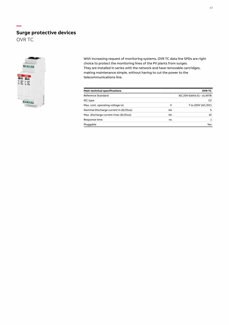
—Surge protective devices OVR TC
With increasing request of monitoring systems, OVR TC data line SPDs are right choice to protect the monitoring lines of the PV plants from surges. They are installed in series with the network and have removable cartridges, making maintenance simple, without having to cut the power to the telecommunications line.
Main technical specifications OVR TC
Reference Standard IEC/EN 61643-21 - UL497B
IEC type C2
Max. cont. operating voltage Uc V 7 to 220V (AC/DC)
Nominal Discharge current In (8/20us) kA 5
Max. discharge current Imax (8/20us) kA 10
Response time ns 1
Pluggable Yes
47

Rapid Shutdown PV Vault• Application: Residential and Small Commercial Rooftop• Meets NEC 690.12-2014, UL 1741 and CSA C22 requirements• 600V DC/20amps or less• Connects 2 to 4 strings/arrays• Dual MPPT outputs maintain the benefits of inverter channels• NEMA 4X enclosure permits 0-90 degree• Discharges PV array within 10 seconds• Local On/Off selector switch• Quick installation with two connections
PV String 1
PV output MPPT1
Inverter
PV system disconnect
Controlvault
Utilitygrid
PV output MPPT2
+24V RSD power
ABB rapidshutdown
PV String 2
PV String 3
PV String 4
< 10 ft.
Control vault
—Rapid shutdown PV Vault
48 S O LUTI O N S FO R S O L A R E N E RGY

In a photovoltaic system, the modules are arranged in strings and fields depending on the type of inverter used, the total power and the technical characteristics of the modules. The connection of modules in series is made on the modules themselves, while the parallel connection of the strings is realized in the so-called “string boxes” that accommodate, along with the interconnection systems, also the overcurrent protection devices, disconnectors and surge protection devices. In medium and large sized systems, the string boxes form subsystems that can be standardized according to the number of strings, voltage and rated current.ABB offers four different product ranges, each dedicated to specific installation conditions with typical configurations.
String boxesThe installation of a photovoltaic system often occurs in complex logistic situations, critical from the environmental and time perspective. The availability of tested and certified pre-assembled components allows the installer to avoid unnecessary on site assembly, wiring and certification activities for the string boxes. String boxes enclose functions such as string protection, protection against overvoltage and disconnect, with components suitable for the string’s various voltage levels and the number of connected strings.
Multi-output string boxesThe development and the increasingly frequent adoption of multi-string inverters has made it necessary to reduce the costs and the space occupied by the string boxes, to bring together in a single switchboard the protective devices and disconnectors of multiple strings intended to be connected to a specific inverter input. Multi-string inverters resolve in an easy and cost-effective manner system conditions characterized by modules installed in different leaning and exposure positions or minimize the problems related to systematic shading of parts of the system.
String boxes for monitoringThe string monitoring is an important function in running medium and large size installations, since it allows to improve the manufacturability and maintenance of the system. ABB offers a series of pre-wired string boxes for all installation conditions: they are equipped both with devices necessary for string protection, surge protection and disconnection, and with useful devices for string monitoring.
Highlights:• 1000V DC and 1500V DC String combiner boxes• 1 Strings - 32 Strings without monitoring• 12 Strings - 32 Strings with monitoring (Current monitoring as standard) • Enclosure: Gemini Thermoplastic, IP66, UV resistant, IK10• Fuse holders 30A and cylindrical fuses 10.3x38mm• Integrated disconnect switch • Protection for both positive and negative• Surge Protection Devices: OVR PV QS
Optional Features• Monitoring for voltage, temperature and status of the disconnector• Positive protected versions for grounded systems• Grounded or ungrounded negative• Pole mounting kit• Base mounting kit
—DC Combiner Boxes
49
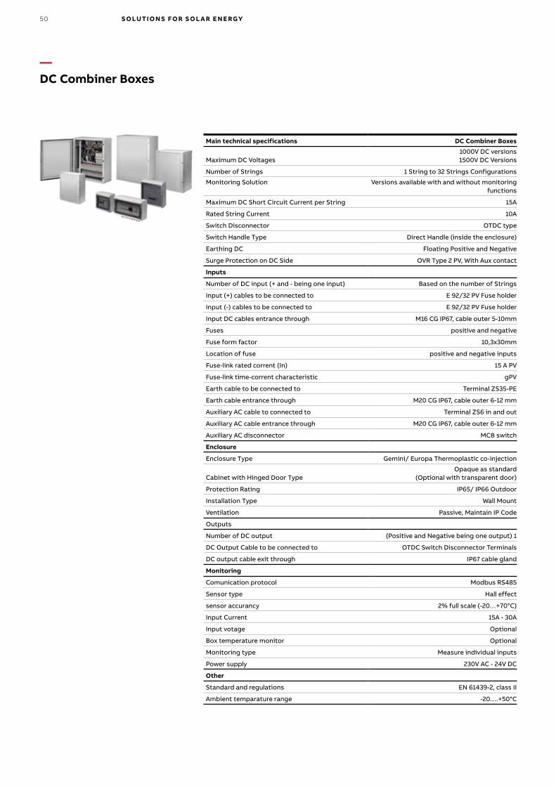
—DC Combiner Boxes
Main technical specifications DC Combiner Boxes
Maximum DC Voltages1000V DC versions1500V DC Versions
Number of Strings 1 String to 32 Strings Configurations
Monitoring Solution Versions available with and without monitoring functions
Maximum DC Short Circuit Current per String 15A
Rated String Current 10A
Switch Disconnector OTDC type
Switch Handle Type Direct Handle (inside the enclosure)
Earthing DC Floating Positive and Negative
Surge Protection on DC Side OVR Type 2 PV, With Aux contact
Inputs
Number of DC input (+ and - being one input) Based on the number of Strings
Input (+) cables to be connected to E 92/32 PV Fuse holder
Input (-) cables to be connected to E 92/32 PV Fuse holder
Input DC cables entrance through M16 CG IP67, cable outer 5-10mm
Fuses positive and negative
Fuse form factor 10,3x30mm
Location of fuse positive and negative inputs
Fuse-link rated corrent (In) 15 A PV
Fuse-link time-corrent characteristic gPV
Earth cable to be connected to Terminal ZS35-PE
Earth cable entrance through M20 CG IP67, cable outer 6-12 mm
Auxiliary AC cable to connected to Terminal ZS6 in and out
Auxiliary AC cable entrance through M20 CG IP67, cable outer 6-12 mm
Auxiliary AC disconnector MCB switch
Enclosure
Enclosure Type Gemini/ Europa Thermoplastic co-injection
Cabinet with Hinged Door TypeOpaque as standard
(Optional with transparent door)
Protection Rating IP65/ IP66 Outdoor
Installation Type Wall Mount
Ventilation Passive, Maintain IP Code
Outputs
Number of DC output (Positive and Negative being one output) 1
DC Output Cable to be connected to OTDC Switch Disconnector Terminals
DC output cable exit through IP67 cable gland
Monitoring
Comunication protocol Modbus RS485
Sensor type Hall effect
sensor accurancy 2% full scale (-20…+70°C)
Input Current 15A - 30A
Input votage Optional
Box temperature monitor Optional
Monitoring type Measure individual inputs
Power supply 230V AC - 24V DC
Other
Standard and regulations EN 61439-2, class II
Ambient temparature range -20….+50°C
50 S O LUTI O N S FO R S O L A R E N E RGY
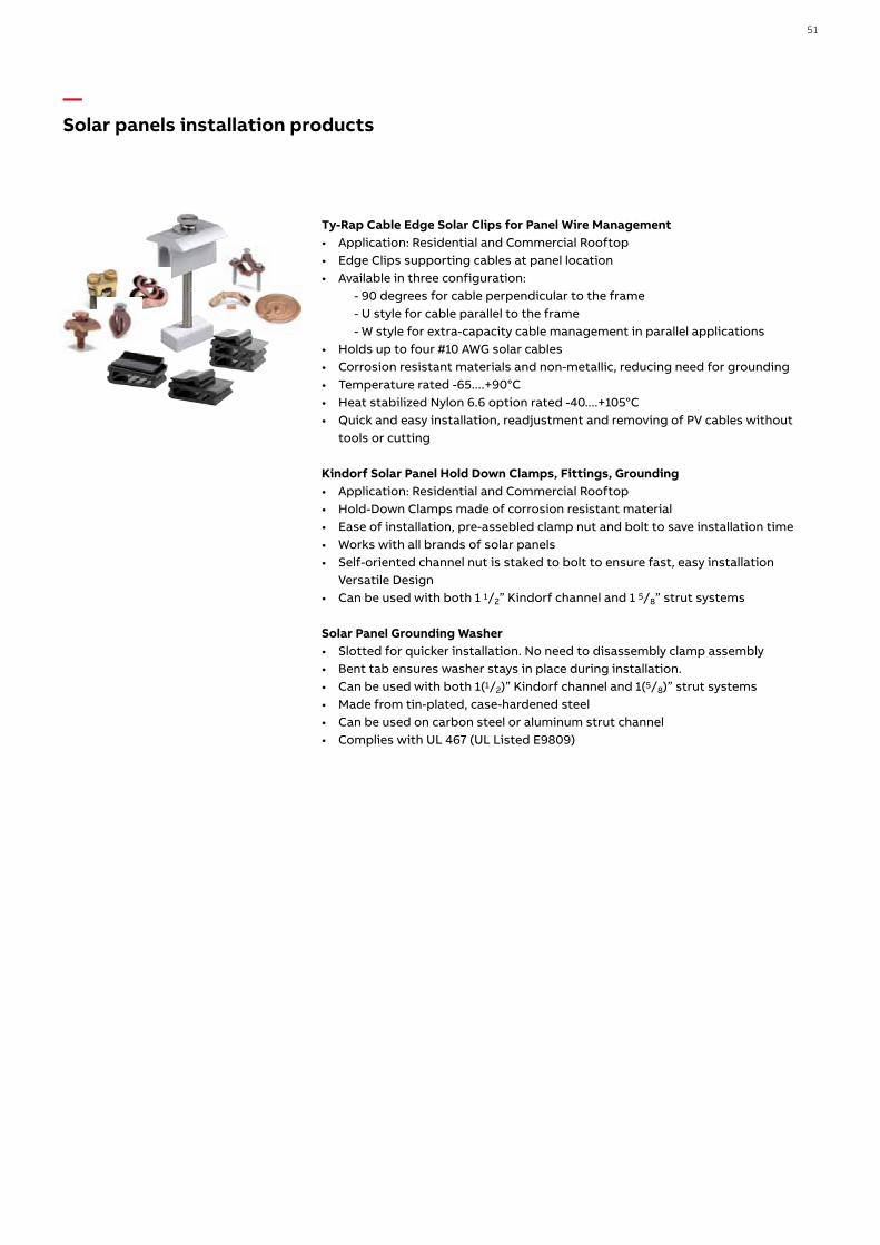
Ty-Rap Cable Edge Solar Clips for Panel Wire Management• Application: Residential and Commercial Rooftop• Edge Clips supporting cables at panel location• Available in three configuration: - 90 degrees for cable perpendicular to the frame - U style for cable parallel to the frame - W style for extra-capacity cable management in parallel applications• Holds up to four #10 AWG solar cables• Corrosion resistant materials and non-metallic, reducing need for grounding• Temperature rated -65....+90°C• Heat stabilized Nylon 6.6 option rated -40....+105°C• Quick and easy installation, readjustment and removing of PV cables without
tools or cutting
Kindorf Solar Panel Hold Down Clamps, Fittings, Grounding• Application: Residential and Commercial Rooftop• Hold-Down Clamps made of corrosion resistant material• Ease of installation, pre-assebled clamp nut and bolt to save installation time• Works with all brands of solar panels• Self-oriented channel nut is staked to bolt to ensure fast, easy installation
Versatile Design• Can be used with both 1 1/2” Kindorf channel and 1 5/8” strut systems
Solar Panel Grounding Washer• Slotted for quicker installation. No need to disassembly clamp assembly• Bent tab ensures washer stays in place during installation.• Can be used with both 1(1/2)” Kindorf channel and 1(5/8)” strut systems• Made from tin-plated, case-hardened steel• Can be used on carbon steel or aluminum strut channel• Complies with UL 467 (UL Listed E9809)
—Solar panels installation products
SOLUTIONS FOR THE DC SIDE
• MC4-Evo2 - photovoltaic connectors
• DBL - distribution terminal blocks
• Solar panels installation products and Grounding systems
Connection and Installation
51

—Photovoltaic systems Products for AC side
52 S O LUTI O N S FO R S O L A R E N E RGY

53

—Switchboards Gemini IP 66
Main technical specifications Gemini IP 66
Protection
Protection class IP 66 (CEI EN 60529)
Insulation class II
Strength
Material joint-injection moulded thermo-plastic
Heat and fire resistance up to 750 °C (IEC EN 60695-2-11)
Shock resistance IK10 (IEC EN 50102)Protection against chemicals and weather conditions
water, saline solutions, acids, basics, mineral oils, UV rays
Operating temperature -25 °C…+100 °C
Performance
Nominal insulation voltage 1000V AC – 1500V DC
Flexibility WxHxD, external dimensions
6 sizes from 335 x 400 x 210 mm to 840 x 1005 x 360 mm
DIN modules from 24 to 216
Installation Snap-in assembly of all componentsStandards, quality, environment IEC EN 50298, IEC 23-48, IEC 23-49,
IEC 60670, IEC EN 60439-1 IMQ Mark according to the IEC EN 50298 standard. Fully recyclable
Boxes and doors• RAL 7035 grey color
SizeExternal
WxHxD (mm)Internal
WxHxD (mm)Max num.DIN mod.
1 335x400x210 250x300x180 24 (12x2)
2 460x550x260 375x450x230 54 (18x3)
3 460x700x260 375x600x230 72 (18x4)
4 590x700x260 500x600x230 96 (24x4)
5 590x855x360 500x750x330 120 (24x5)
6 840x1005x360 750x900x330 216 (36x6)
54 S O LUTI O N S FO R S O L A R E N E RGY

SizeExternal
WxHxD (mm)Internal
WxHxD (mm)Max num.DIN mod.
1 335x400x210 250x300x180 24 (12x2)
2 460x550x260 375x450x230 54 (18x3)
3 460x700x260 375x600x230 72 (18x4)
4 590x700x260 500x600x230 96 (24x4)
5 590x855x360 500x750x330 120 (24x5)
6 840x1005x360 750x900x330 216 (36x6)
—Switchboards Gemini UL IP 66
Main technical specifications Gemini UL IP 66
Protection
Protection class UL IP 66 (CEI EN 60529)
Insulation class II
Strength
Material joint-injection moulded thermo-plastic
Heat and fire resistance up to 960 °C (IEC EN 60695-2-11)
Shock resistance IK10 (IEC EN 50102)
Protection against chemicals and weather conditions
water, saline solutions, acids, basics, mineral oils, UV rays
Operating temperature -4°F up to 158°F (-20°C up to 70°C)…+100 °C
Performance
Nominal insulation voltage 1000V AC – 1500V DC
Flexibility WxHxD, external dimensions
6 sizes from 335 x 400 x 210 mm to 840 x 1005 x 360 mm
DIN modules from 24 to 216
Installation Snap-in assembly of all components
Standards, quality, environment
NEMA Types: 1, 3R, 4, 4XUL Listed: UL508A, UL50, UL50E
CSA Listed: C22.2 Nr14
Boxes and doors• RAL 7035 grey color • only opaque door available
SizeExternal
WxHxD (mm)Internal
WxHxD (mm)Max num.DIN mod.
1 335x400x210 250x300x180 24 (12x2)
2 460x550x260 375x450x230 54 (18x3)
3 460x700x260 375x600x230 72 (18x4)
4 590x700x260 500x600x230 96 (24x4)
5 590x855x360 500x750x330 120 (24x5)
6 840x1005x360 750x900x330 216 (36x6)
55

ABB provides IP65 polycarbonate junction boxes that are perfect for use in outdoor installations.The main features of the junction boxes include:• class II insulation• manufactured in self-extinguishing thermoplastic material able to withstand
abnormal heat and fire up to 960 °C (glow wire test) in compliance with IEC 60695-2-11 standards
• installation temperature: -25 °C to +60 °C• nominal insulation voltage: 1000V AC; 1500V DC• shock resistance: 20 joules (IK 10 degrees)• junction boxes in compliance with IEC 23-48 and IEC 60670 standards• IMQ approved
—EUROPA65 junction boxes
Description Type Dimensions (mm)
Box IP65 PC 140x220x140
Box IP65 PC 205x220x140
Box IP65 PC 275x220x140
Box IP65 PC 275x370x140
Box IP65 PC 275x570x140
Box IP65 PC 380x570x140
The Europa series wall-mounting units feature IP65 protection which makes them ideal for outdoor installation. This means that they can be used for making string boxes on the load side of photovoltaic strings.The main features of the Europa series wall-mounted units include:• class II insulation• manufactured in self-extinguishing thermoplastic material able to withstand
abnormal heat and fire up to 960 °C (glow wire test) in compliance with IEC 60695-2-11 standards
• installation temperature: -25 °C to +60 °C• nominal insulation voltage: 1000V AC; 1500V DC• shock resistance: 20 joules (IK 10)• pull-out DIN rails holder frame for more convenient bench wiring.
Can be disassembled (and re-assembled by means of a snap-fit mechanism) to make the individual wires easier to route
• 53, 68 and 75 mm depth switchgear can be installed• consumer units in compliance with IEC 23-48, IEC 23-49 and IEC 60670 standards
—Wall mounting consumer units EUROPA65 series
Description Type Dimensions (mm)
IP65 consumer unit P/smoke grey 8M 205x220x140
IP65 consumer unit P/smoke grey 12M 275x220x140
IP65 consumer unit P/smoke grey 18M 1 row 380x220x140
IP65 consumer unit P/smoke grey 24M 2 rows 275X370X140
IP65 consumer unit P/smoke grey 36M 2 rows 380x370x140
56 S O LUTI O N S FO R S O L A R E N E RGY

Miniature circuit breakers are necessary also on the AC side of the PV installation for protection of electric lines and equipment from overload and short circuit. They provide protection of the cables that exit from inverter to the network as well as the different auxiliary circuits of the PV inverters.
S 200S 200 is enhanced series of miniature circuit breakers.The main features of the S 200 MCBs are:• Available with all the tripping curve B, C, D, K and Z.• Terminal for cable up to 35 mm 2 with protective flap to avoid accidental contact
with the live parts.• High temperature and shocks resistance thanks to a new type of thermoplastic
materials• Indelible laser screen-printing• Multiple certification marks visible on the upper and lower face of the S200 circuit
breakers.
Main technical specifications S 200
Reference Standard IEC 60898, IEC/EN 60947-2, UL 1077
Nominal Current (In) A 0,5 … 63
Breaking capacity (Icu) kA 6 (S200), 10 (S200M), 15 (S200P), 25 (S200P)
Nominal Voltage (Ue) V AC 1P: 12 … 230 / 2P ... 4P: 12 … 400
Operation Temperature C -25 … +55
S800S800 is a high performance miniature circuit breaker.The main features of the S800 HPMCBs are:• Designed for high short-circuit protection up to 50 kA• Available with tripping curves B, C, D and K.• Switch with intermediate trip position (TRIP).• Differentiate manual actuation from over-current trip.
Main technical specifications S800
Reference Standard IEC 60898, IEC/EN 60947-2
Nominal Current (In) A 6 … 125
Breaking capacity (Icu) kA 16 (S800B), 25 (S800C), 36 (S800N), 50 (S800S)
Nominal Voltage (Ue) V AC 1P: 12 … 230 / 2P ... 4P: 12 … 400Operation Temperature C -25…+60
—Miniature Circuit BreakersS 200, S800
57

Residual current circuit-breakers type B are also sensitive to fault currents with a low ripple level, similar to continuous fault currents. They however remain sensitive to sinusoidal alternating and pulsating continuous earth fault currents. When a photovoltaic plant includes an inverter without at least a simple DC/AC separation, it’s necessary to install on DC side an RBCO of B class, according to IEC 60364-7 art. 712.413.1.1.1.2: “Where an electrical installation includes a PV power supply system without at least simple separation between the AC side and the DC side, an RCD installed to provide fault protection by automatic disconnection of supply should be type B. If the PV inverter by construction is not able to feed DC fault current into the electrical installation a B-type RCD is not mandatory”.
Main technical specifications F200 type B
Rated current In 25, 40, 63, 125 A
Rated sensitivity IΔn 0.03 - 0.3 - 0.5 A
Operating frequency range 0 - 1000 Hz
Minimum supply voltage• to detect currents of type A / AC• to detect currents of type B
0 V30V AC
Number of poles 2P, 4P
Conditional short-circuit current Inc 10 kA
Conditional residual short-circuit current IΔc 10 kA
IP ClassIP40 (when installed into a switchboard)
Operating temperature -25°C...+40°C
Reference standards IEC 62423 ed. 2
On the other hand, in case a DC/AC electrical separation exists, residual current circuit breaker type A can be used.
Main technical specifications F200 A
Reference Standard Standard IEC/EN 61008
Nominal Current (In) A 16 … 125
Nominal Voltage (Ue) V AC 230…400
Sensitivity mA 10 – 30 – 100 – 300 – 500
Number of poles 2P, 4P
Operation Temperature C -25…+55
—Residual Current Circuit-breakers (RCCBs) F200, F204 B, F202 B
58 S O LUTI O N S FO R S O L A R E N E RGY

DDA202 B, DDA203 B and DDA204 B RCD-blocks type B are also sensitive to fault currents with a low level ripple similar to continuous fault currents. If used in combination with S200 series MCBs, they assure the protection of people and installations against fire risks, short circuit and overcurrents. They however remain sensitive to sinusoidal alternating and pulsating continuous earth fault currents. When a electrical system includes a PV power system without at least a simple DC/AC separation, the residual device installed to provide protection against indirect contact by automatic supply disconnection must be of type B according to IEC 62423 ed.2 (IEC 60364-7 art. 712.413.1.1.1.2) standard.
Main technical specifications DDA200 type B
Type B (instantaneous) and B S (selective)
Rated current In A 25, 40, 63
Rated sensitivity I∆n A 0.03 - 0.3 - 0.5
Operating frequency range Hz 0 - 1000
Operating voltage V 230…400
Number of poles 2P - 3P - 4P
Ambient temperature °C -25...+55
Reference standards IEC 61009 Annex G, IEC 62423 ed.2
—Residual Current devices (RCDs) DDA200 type B
59

Moulded-case circuit-breakers can be used in low-voltage civil and industrial installations with 10 A to 3200 A operating current. The Tmax family includes 9 circuit-breaker sizes in three- or four-pole versions:
• XT1, XT2, XT3 and XT4 up to 250A;• T4, T5 and T6 up to 1000A;• T7 and T8 up to 3200A.
Main characteristics of the Tmax family are:• High breaking capacity in compact dimensions: the ultimate short-circuit
breaking capacity (Icu) at 415V ranges from 18kA to 200kA, or up to 80kA for 690V
• Ease of use and installation flexibility: a complete range of mechanical and electrical cabled accessories and a solution for electronic trip units to adapt Tmax to each application scenario
• Increased safety for operators: wide range of keylocks and padlocking options, plug in and withdrawable versions to speed up maintenance operations and improved diagnostic to have ready to use information about breakers’ status
• Information availability: Modbus communication modules for integration in a supervision system and for remote control
—Moulded Case Circuit BreakersTmax
60 S O LUTI O N S FO R S O L A R E N E RGY

Tmax PV T4V-HA and T5V-HA circuit breakers for AC applications are available in UL type-approved versions and versions that conform to Standards IEC 60947-2 and GB14048.2. The T4V-HA version bearing the three UL, IEC and CCC marks and T5V-HA bearing both the IEC and UL marks can be supplied. Size T4 controls currents up to 250A and can break short-circuit current up to 25kA, while size T5 controls currents up to 630A and breaks short-circuit current up to 32kA. To be highlighted that T4V-HA UL up to 150A and T5V-HA UL are 100% rated. Ideal for protecting AC switchgear and string inverters, these circuit-breakers can be integrated with the entire range of electrical and mechanical accessories already available for the SACE Tmax T moulded-case circuit breaker range.
—Moulded Case Circuit Breakers Tmax PV
T4V-HA T5V-HARated uninterrupted current [A] 80, 100, 125, 160, 200, 250 320 400 500 630Rated service voltage [V] 800 800Rated impulse withstand voltage, Uimp [kV] 8 8Rated insulation voltage, Ui [V] 1000 1000Distribution System IT, TN IT, TNRated breaking capacity, Icu [kA] 25 32Rated service breaking capacity, Ics [kA] 12 16Category of use (IEC 60947-2) A AIsolation behaviour Yes YesReference Standards IEC60947-2/GB14048.2 IEC60947-2/GB14048.2Product Certification IEC - CCC IEC - CCCTrip unit type TMA TMA PR221Poles 3P/4P 3P/4PClass of pollution III IIIDerating on uninterrupted current @ 4000m 93% 93%Working Temperature [°C] -25 + 70 -25 + 70Electrical life [No. Operations] 2000 1000Mechanical life [No. Operations] 20000 20000Version F FTerminals (cables, busbars) Front, FcCuAl (1x185), FcCu (1x185) Front, FcCuAl (1x240), FcCu (1x240) Front
T4V-HA T5V-HARated uninterrupted current [A] 80, 100,125,150, 200 300Rated 100% up to 150A, 80% at 200A 100%Rated service voltage [V] 800 800 Rated impulse withstand voltage, Uimp [kV] 8 8Rated insulation voltage, Ui [V] 1000 1000Distribution System Δ ΔShort circuit interrupting rating [kA] 25 25Isolation behaviour Yes YesReference Standards UL489 UL489Product Certification UL - IEC - CCC UL - IECTrip unit type TMA TMA, PR221Poles 3P/4P 3P/4PClass of pollution III IIIDerating on uninterrupted current @ 4000m 93% 93%Working Temperature [°C] -25 + 70 -25 + 70Electrical life [No. Operations] 4000 1000Mechanical life [No. Operations] 20000 20000Version F FTerminals FcCuAl (1x350kcmil) FcCuAl (1x500kcmil)
IEC
UL
Main technical specifications
61
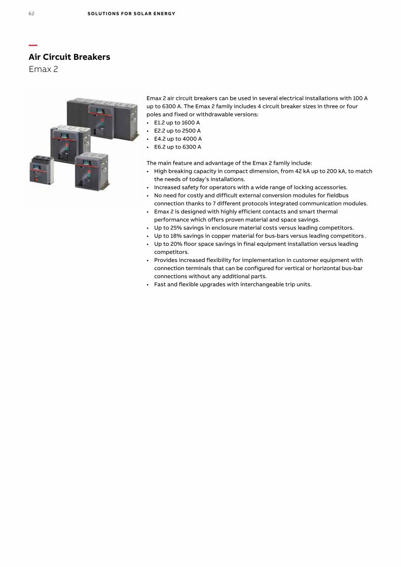
Emax 2 air circuit breakers can be used in several electrical installations with 100 A up to 6300 A. The Emax 2 family includes 4 circuit breaker sizes in three or four poles and fixed or withdrawable versions:• E1.2 up to 1600 A• E2.2 up to 2500 A• E4.2 up to 4000 A• E6.2 up to 6300 A
The main feature and advantage of the Emax 2 family include:• High breaking capacity in compact dimension, from 42 kA up to 200 kA, to match
the needs of today’s installations.• Increased safety for operators with a wide range of locking accessories.• No need for costly and difficult external conversion modules for fieldbus
connection thanks to 7 different protocols integrated communication modules.• Emax 2 is designed with highly efficient contacts and smart thermal
performance which offers proven material and space savings.• Up to 25% savings in enclosure material costs versus leading competitors.• Up to 18% savings in copper material for bus-bars versus leading competitors .• Up to 20% floor space savings in final equipment installation versus leading
competitors.• Provides increased flexibility for implementation in customer equipment with
connection terminals that can be configured for vertical or horizontal bus-bar connections without any additional parts.
• Fast and flexible upgrades with interchangeable trip units.
—Air Circuit BreakersEmax 2
62 S O LUTI O N S FO R S O L A R E N E RGY
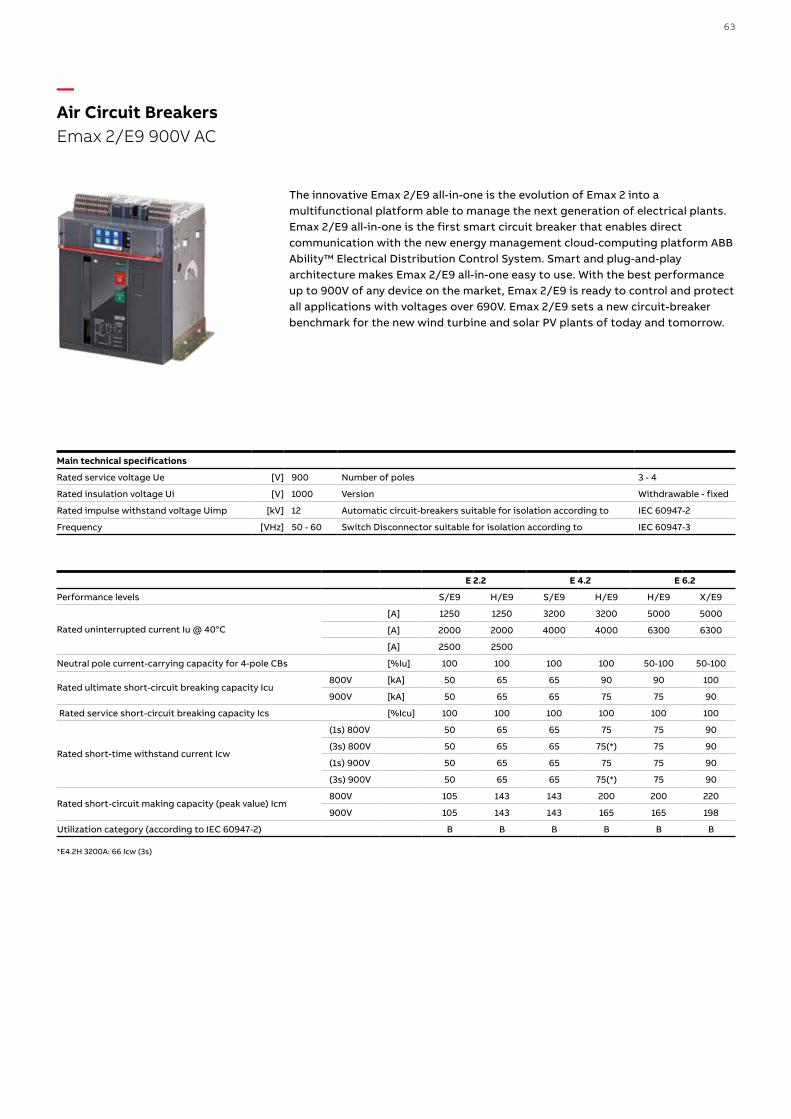
The innovative Emax 2/E9 all-in-one is the evolution of Emax 2 into a multifunctional platform able to manage the next generation of electrical plants. Emax 2/E9 all-in-one is the first smart circuit breaker that enables direct communication with the new energy management cloud-computing platform ABB Ability™ Electrical Distribution Control System. Smart and plug-and-play architecture makes Emax 2/E9 all-in-one easy to use. With the best performance up to 900V of any device on the market, Emax 2/E9 is ready to control and protect all applications with voltages over 690V. Emax 2/E9 sets a new circuit-breaker benchmark for the new wind turbine and solar PV plants of today and tomorrow.
—Air Circuit Breakers Emax 2/E9 900V AC
Main technical specifications
Rated service voltage Ue [V] 900 Number of poles 3 - 4
Rated insulation voltage Ui [V] 1000 Version Withdrawable - fixed
Rated impulse withstand voltage Uimp [kV] 12 Automatic circuit-breakers suitable for isolation according to IEC 60947-2
Frequency [VHz] 50 - 60 Switch Disconnector suitable for isolation according to IEC 60947-3
E 2.2 E 4.2 E 6.2
Performance levels S/E9 H/E9 S/E9 H/E9 H/E9 X/E9
Rated uninterrupted current Iu @ 40°C
[A] 1250 1250 3200 3200 5000 5000
[A] 2000 2000 4000 4000 6300 6300
[A] 2500 2500
Neutral pole current-carrying capacity for 4-pole CBs [%Iu] 100 100 100 100 50-100 50-100
Rated ultimate short-circuit breaking capacity Icu800V [kA] 50 65 65 90 90 100
900V [kA] 50 65 65 75 75 90
Rated service short-circuit breaking capacity Ics [%Icu] 100 100 100 100 100 100
Rated short-time withstand current Icw
(1s) 800V 50 65 65 75 75 90
(3s) 800V 50 65 65 75(*) 75 90
(1s) 900V 50 65 65 75 75 90
(3s) 900V 50 65 65 75(*) 75 90
Rated short-circuit making capacity (peak value) Icm800V 105 143 143 200 200 220
900V 105 143 143 165 165 198
Utilization category (according to IEC 60947-2) B B B B B B
*E4.2H 3200A: 66 Icw (3s)
63

0 0,5 1 1,5 2 t (s)
U (V
) U_coil
Uc = control circuit voltage
U_drop out level
16 % of Uc max.
The AF..T range is specially designed for renewable energy AC switching applications with “Low-voltage Ride Through” function. The AF..T contactor is able to withstand a voltage drop on the control voltage without opening. The built-in drop-out delay circuit provides enough energy for the coil voltage to remain above the drop-out level.
Main technical specifications AF1350T – AF2650T
Reference standards IEC60947-1, -4-1
Rated operational voltage 1000 V
Current ratings 1350 – 2050 A
Control voltage, AF range Electronically controlled AC/DC
Number of poles 3
SD 200 switches disconnectors can be used as the main switch of the AC side of the inverters. The devices are mounted on a DIN rail or on the rear panel of a switchboard (depending on the rated current) and include a wide range of accessories, facilitating their use in various applications.
Main technical specifications SD 200
Reference Standard Standard IEC 60947-3
Rated Current (In) A 16…63
Rated Voltage (Ue) V AC 253/440
Operation Temperature C -25…+55 °C
—Contactors (for grid compliance) AF..T range
—Switch-disconnectorsSD 200
64 S O LUTI O N S FO R S O L A R E N E RGY
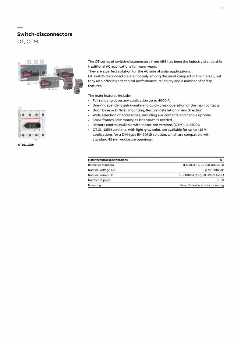
The OT series of switch-disconnectors from ABB has been the industry standard in traditional AC applications for many years. They are a perfect solution for the AC side of solar applications. OT switch-disconnectors are not only among the most compact in the market, but they also offer high technical performance, reliability and a number of safety features.
The main features include:• Full range to cover any application up to 4000 A• User-independent quick-make and quick-break operation of the main contacts• Door, base or DIN-rail mounting, flexible installation in any direction• Wide selection of accessories, including aux contacts and handle options• Small frames save money as less space is needed• Remote control available with motorized versions (OTM) up 2500A• OT16...125M versions, with light gray color, are available for up to 415 V
applications for a DIN-type EN 60715 solution, which are compatible with standard 45 mm enclosure openings.
Main technical specifications OT
Reference standard IEC 60947-3, UL 508 and UL 98
Nominal voltage, Ue up to 1000V AC
Nominal current, In 16 - 4000 A (IEC), 20 - 2000 A (UL)
Number of poles 1 ... 8
Mounting Base, DIN rail and door mounting
OT16...125M
—Switch-disconnectorsOT, OTM
65

To provide efficient protection for a photovoltaic system the alternate current side must also be protected against overvoltage.OVR T1, Type-1 SPD, is installed in the main (AC side) switchboard at the system input and is able to conduct the direct lightning current to earth and to ensure safety in the case of a direct lightning strike.OVR T2, Type-2 SPDs, are installed on the load side of the inverter and in possible other sub-switchboard to protect against switching surges and the indirect effect of lightning.
The main features of the OVR range are:• Network configuration in single pole, 3 poles, 1 Phase+N and 3 Phases+N• Simplified maintenance with the pluggable cartridges (P option)• Increased security with the safety reserve (S option)• Remote indication with the auxiliary contact (TS option)• Certified to the last IEC 61643-11:2012 standard with the QuickSafe technology3.
Main technical specifications OVR T1 OVR T1-T2 QS OVR T2 QS
Reference Standards IEC EN 61643-11 / UL 1449 3rd edition* IEC EN 61643-11
IEC EN 61643-11 / UL 1449 3rd edition*
IEC Type T1 / I T1-T2 / I-II T2 / II
Max. cont. Operating Voltage Uc V 255 275 275
Nominal discharge current In (8/20 μs) kA 25 30 5, 20 and 30
Impulse current limp (10/350 μs) kA 25 12.5 /
Maximum discharge current Imax (8/20 μs) kA / 80 20, 40 and 70
Response time ns < 100 < 25 < 25
Safety reserve / yes “S” Version
Pluggable / “P” Version “P” Version
Remote indicator “TS” Version “TS” Version “TS” Version
* UL Version only for OVR T2 U
—Surge protective devices OVR T1, OVR T2
66 S O LUTI O N S FO R S O L A R E N E RGY

CM-UFD.MxxM range are multi-functional grid feeding monitoring relays, installed between the renewable energy system and the public grid. They detect unusual events in the public power grid and automatically disconnect and reconnect the renewable power plant. Different monitoring functions such as 10-minutes average value, real time over- and undervoltage as well as over- and underfrequency are configurable via the front face display. Versions with a Modbus RTU communication interface are available as well.
Key features:
• Modbus RTU interface enables remote visualization and storage of process data as well as remote tripping
• Easy to configure due to backlit LCD display• LOM (Loss of mains) protection, e.g. ROCOF and Vector shift detection• Monitoring of voltage and frequency in single- and three-phase mains• Error memory for up to 99 entries
(incl. cause of error, measured value, relative timestamp)• Password protection
A reliable solution that takes country-specific requirements into account: the CM-UFD range is already pre-set to local requirements, making installation quick and simple. Additionally, the devices can also be set manually with the display and used all over the world.
—Grid feeding monitoring relaysCM-UFD.MxxM
GermanyCM-UFD.M31M
AustriaCM-UFD.M31M
United Arabic EmiratesCM-UFD.M34M
ItalyCM-UFD.M22M
Great BritainCM-UFD.M33M
TurkeyCM-UFD.M31Mrefers to DE standard
AustraliaCM-UFD.M33M
JordanCM-UFD.M33Mrefers to GB standard
SwitzerlandCM-UFD.M31M
South AfricaCM-UFD.M31MCM-UFD.M22M
Countries with a dedicated local standard (in red).Countries referring to an existing local standard or using a product with reference to another dedicated standard (in grey).
67

Modular energy meters are ideal for metering and monitoring the energy produced by a photovoltaic system downstream of the inverter. ABB EQ meters are compliant and tested according to the European MID directive, which allows meters to be used whenever an energy consumption reading is requested for billing.
The EQ meters are available in three different product ranges, A, B and C seriesA series:• Single phase or three phase• Direct connected up to 80 A or transformer current- and/or voltage transformers
(CTVT)• Active energy measurement Class B (Cl. 1) or Class C (Cl. 0,5 S) on CTVT
connected meters• Wide voltage range 100 - 500 V phase to phase 57,7 - 288 V phase to neutral• Alarm function• MID• Reactive energy measurement• Import/export measurement of energy• Optional communication via M-Bus or RS-485• 4 tariffs controlled by inputs, communication or built-in clock• Previous values (by day, week or month)• Demand measurement (max and min)• Load profiles (8 channels)• Harmonics measurement up to 16th harmonic and evaluation of THD
B series:• Single phase or three phase• Direct connected up to 65 A or CT connected (three phase versions)• Active energy measurement Class B (Cl. 1) or Class C (Cl. 0,5 S)• Alarm function• MID• Reactive energy measurement• Import/export measurement of energy• Optional communication via M-Bus or RS-485• 4 tariffs controlled by input or communication
C series:• Single phase or three phase• Very compact, 1 and 3 modules.• Direct connected up to 40 A• Active energy measurement• Instrument values• Accuracy class 1 or class B (MID versions)• Alarm function• Optional MID
—Modular energy meters EQ meters
68 S O LUTI O N S FO R S O L A R E N E RGY

StandardsIEC 62052-11, IEC 62053-21class 1 and 2, IEC 62053-22 class 0,5 S, IEC 62053-23 class 2, IEC 62054-21, EN 50470-1, EN 50470-3 category A, B and C.
CommunicationBuilt-in communication interfaces and separate communication devices enable serial data communication between energy meter and remote supervision system. Data on energy consumption and electrical parameters to be collected via serial protocols such as: Modbus RTU, M-Bus, Ethernet TCP/IP and KNX.
CT current transformersWhenever indirect measurement is required, CT current transformers are the best solution to create a complete plant, ensuring long-term accuracy and precision of measurements.
Serial Communication AdaptersCommunication adapters allow the serial data communication between energy meter and remote supervision system. The adapters allow data on energy consumption and electrical parameters to be collected via serial protocols such as: Modbus RTU, MeterBus, MeterBus, Ethernet TCP/IP, KNX.
69
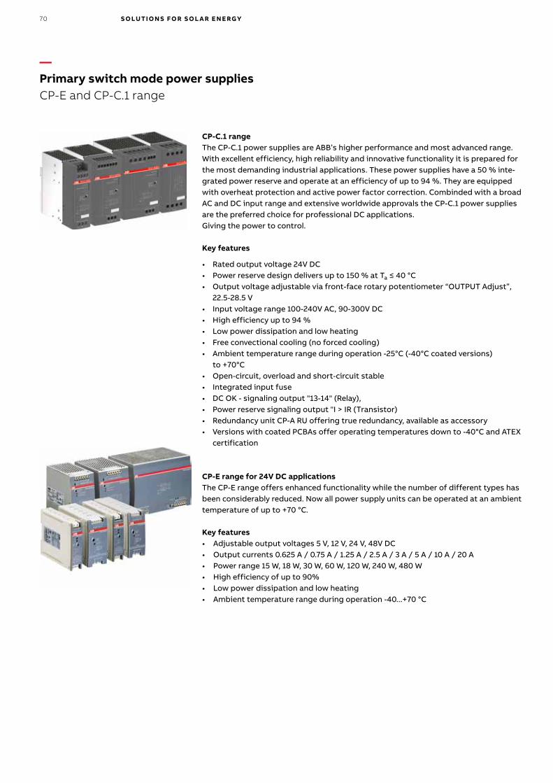
CP-C.1 rangeThe CP-C.1 power supplies are ABB’s higher performance and most advanced range. With excellent efficiency, high reliability and innovative functionality it is prepared for the most demanding industrial applications. These power supplies have a 50 % inte-grated power reserve and operate at an efficiency of up to 94 %. They are equipped with overheat protection and active power factor correction. Combinded with a broad AC and DC input range and extensive worldwide approvals the CP-C.1 power supplies are the preferred choice for professional DC applications.Giving the power to control.
Key features
• Rated output voltage 24V DC• Power reserve design delivers up to 150 % at Ta ≤ 40 °C• Output voltage adjustable via front-face rotary potentiometer “OUTPUT Adjust”,
22.5-28.5 V• Input voltage range 100-240V AC, 90-300V DC• High efficiency up to 94 %• Low power dissipation and low heating• Free convectional cooling (no forced cooling)• Ambient temperature range during operation -25°C (-40°C coated versions)
to +70°C• Open-circuit, overload and short-circuit stable• Integrated input fuse• DC OK - signaling output "13-14" (Relay),• Power reserve signaling output "I > IR (Transistor)• Redundancy unit CP-A RU offering true redundancy, available as accessory• Versions with coated PCBAs offer operating temperatures down to -40°C and ATEX
certification
CP-E range for 24V DC applicationsThe CP-E range offers enhanced functionality while the number of different types has been considerably reduced. Now all power supply units can be operated at an ambient temperature of up to +70 °C.
Key features• Adjustable output voltages 5 V, 12 V, 24 V, 48V DC• Output currents 0.625 A / 0.75 A / 1.25 A / 2.5 A / 3 A / 5 A / 10 A / 20 A• Power range 15 W, 18 W, 30 W, 60 W, 120 W, 240 W, 480 W• High efficiency of up to 90%• Low power dissipation and low heating• Ambient temperature range during operation -40...+70 °C
—Primary switch mode power suppliesCP-E and CP-C.1 range
70 S O LUTI O N S FO R S O L A R E N E RGY
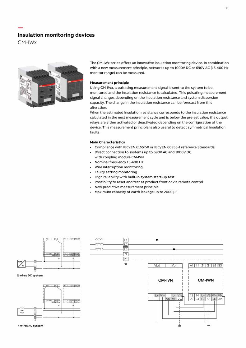
PWM
DC
L+
L-
PE
A1 11 S2 S321 S1
wL+ VS12 14
A2V1-V1+
22 24 L- KE
VL+ VL-
VwL-L+VE
V1-V1+VS
L1
L2
L3
N
PE
A1 11 S2 S321 S1
wL+ VS12 14
A2V1-V1+
22 24 L- KE
VL+ VL-
VwL-L+VE
V1-V1+VS
L+ VS12 14A2V1-V1+
22 24 L- KEVL-L+VE
V1-V1+VS
A1 11 S2 S321 S1VL+ VL-
CM-IVN CM-IWN
L1
L2
N
PE
L3
The CM-IWx series offers an innovative insulation monitoring device. In combination with a new measurement principle, networks up to 1000V DC or 690V AC (15-400 Hz monitor range) can be measured.
Measurement principleUsing CM-IWx, a pulsating measurement signal is sent to the system to be monitored and the insulation resistance is calculated. This pulsating measurement signal changes depending on the insulation resistance and system dispersion capacity. The change in the insulation resistance can be forecast from this alteration.When the estimated insulation resistance corresponds to the insulation resistance calculated in the next measurement cycle and is below the pre-set value, the output relays are either activated or deactivated depending on the configuration of the device. This measurement principle is also useful to detect symmetrical insulation faults.
Main Characteristics• Compliance with IEC/EN 61557-8 or IEC/EN 60255-1 reference Standards• Direct connection to systems up to 690V AC and 1000V DC
with coupling module CM-IVN• Nominal frequency 15-400 Hz• Wire interruption monitoring• Faulty setting monitoring• High reliability with built-in system start-up test• Possibility to reset and test at product front or via remote control• New predictive measurement principle• Maximum capacity of earth leakage up to 2000 μF
2 wires DC system
4 wires AC system
—Insulation monitoring devices CM-IWx
71

The insulation monitors CM-IWM.1x provide best and up to date insulation monitoring of modern IT systems in an optimum and state of the art way, fulfilling all the most relevant Standards. The devices can be used in the most flexible way for AC, DC and AC/DC systems even with large leakage capacity to earth (PE). The adjustment of the setting values is simple and user friendly, done on 2 rotary switches on the front of the devices. The measured value, device parameters and device status are indicated via LEDs and easy to read.
Key features• Preventive fire and system protection• Quick fault localisation through selective earth fault detection to L+ and L-• Universal application in non-earthed DC / AC and mixed IT networks with
maximal up to 1000 or 1500 V measurement voltage• Suitable for large earth leakage capacitances up to 1000 or 3000 μF• Simplest setting via engaging rotary switches• For monitoring photovoltaic system, also with thin-film technology• Optimised measuring times – normally shorter than with other available
methods• Monitoring also with voltage-free mains• Measuring circuit with broken wire detection• No additional coupling device required
—Insulation monitoring devicesCM-IWM.1x
72 S O LUTI O N S FO R S O L A R E N E RGY

The ATT modules are GSM telephone actuators for electrical loads remote control over mobile phone network. In particular, the ATT-22 version consists of a control module with 2 outputs and 2 inputs for photovoltaic applications. Instructions and alarms can be sent via SMS message and free phone call rings. Configuration can be accomplished by SMS messages or using the ATT-Tool software. All the ATT modules are supplied with a backup battery, ATT-Tool programming software and PC connecting cable. In addition, the ATT-22E models are equipped with a pre-wired external antenna – essential if the module is installed in locations that do not assure adequate GSM coverage. The modules can be supplied with a modular transformer.
—Remote command devicesGSM ATT
Main technical specifications GSM ATT
GSM module Dual band EGSM900 and GSM1800 for data, sms, fax and voice applications. Full Type Approved conforming to ETSI GSM Phase 2+
Output power Class 4 (2 W@900 MHz ) Class 1 (1 W@1800 MHz )
Power consumption 5 VA
Commands sent by SMS, call rings, DTMF tones, GPRS connection
Incoming alarms SMS, call rings, e-mail, fax
Inputs Digital self-powered max. 20V DC, 2 mA
Analog
input voltage 0...10 Vinput impedance < 10 KOhm / 100 nF
sampling rate 90 ksps
Outputs Relay NO 4 A 250V AC- max 2500 VA
Minimum load 100 mA, 12 V
GSM indicator LED OFFSTEADY
SLOW BLINKFAST BLINK
Device not poweredDevice under power not connected to mobile network, SIM pin code missing or incorrect device
Under power, connected to mobile networkCommunication in progress
Power supply V 12 ±10% AC/DC
Power consumption when transmitting W 2.5
in stand-by W 0.4
Terminal section mm2 2.5
Temperature ambient °C -20...55
storage °C -30...85
Relative humidity ambient 5...95% non condensing
storage 5...95% only external condensation
Modules 4
Protection IP40
Reference standards R&TTE, Directive 1999/5/EG; Low-voltage, Directive 2006/95/CE; EMC, Directive 2004/108/CE
73

— Power collection and grid connection Medium-voltage products and services
74 S O LUTI O N S FO R S O L A R E N E RGY

75

A CSS is made of concrete, glass reinforced polymer (GRP) or steel enclosure and manufactured per the latest standards: IEC 62271-202, GB 17467-2010 AS 62271-202. The preferred material is GRP, since it is light to transport, strong and very resistant to environmental conditions. Designs are available for DC Power Collection, consisting of a power inverter, transformer and MV protection or for AC Power Collection consisting of a step-up distribution transformer and medium-voltage switchgear. The CSS includes an internal arc-tested enclosure to provide the highest safety level for any service or public personnel close to the substation, which is recommended when installed in a public area. It also includes an oil collection pit to protect the environment from oil leakage.
Typical equipment: • SF6 or air-insulated switchgear up to 40.5 kV • Oil transformer up to 3,500 kVA or Dry up to 2,500 kVA
Major options:• Walk-in for simple maintenance vs non walk-in for compact size• Multiple enclosure material options
Main features and benefits• High level of reliability and safety for equipment and personnel
(internal arc tested IAC-AB)• Type tested according to IEC/AS/GB standards for prefabricated substations,
IEC 62271-202 or applicable• Fully enclosed solutions• Most enclosure materials available in industry• All doors are lockable to prevent unauthorized entry• Concrete enclosure with increased corrosion resistance• GRP housings to meet demanding environmental conditions• Enclosures are compartmented and electrically segregated for safety• CSS designs include an oil collection pit for environmental protection in case of
oil leakage• Walk-in option for ease of service• Separate access entries to MV and transformer secondary skid
—These substations are typically installed in locations accessible to the public and ensure protection for all people according to specified service conditions.
Type-tested, arc-tested assembly comprising an enclosure containing medium-voltage switchgear, distribution transformers, low-voltage switchboards, connections and auxiliary equipment to supply LV energy from MV systems.
—Compact Secondary SubstationCompact substations used for energy transformation
76 S O LUTI O N S FO R S O L A R E N E RGY

—Secondary Skid UnitMost economical solution for solar power collection
Skid-mounted substations provide an economical solution. They are easy to transport and install on most sites, making them ideal for remote locations. Pre-engineered designs are available consisting of all of the needed electrical elements for solar systems. Skid-mounted units consist of sub components including a step-up transformer, MV switchgear and an LV switchboard for string inverter connection.
Typical equipment:• SafeRing up to 40.5 kV for MV protection• Oil transformer• Low voltage switchboard for string inverter connection
Optional equipment: • Automation for remote monitoring and control• Switch with fuse to reduce costs in lower rated installations• Dry type transformer to increase safety
Main features and benefits• Easy access to equipment for visual inspection and service• Open-air cooling for maximum efficiency• Compact and easily transportable• Economic solution• MV compartment locking system prevents unauthorized entry
—A popular option in the SSU is to cover the transformer with steel mesh giving efficient cooling and increased safety (SSU-P).
A skid-mounted, compact solution that offers power collection and transforms AC low-voltage to medium-voltage.
77

The EcoFlex eHouse provides both a single module solution for PowerCollection, and a multi-module solution, ideal for expanding an eHouse tosuit Grid Connection requirements. It is delivered as individual modulesto ensure economical ease-of-transport via traditional methods. All of theequipment is fully installed and factory tested to minimize the amount ofsite works required to complete the installation.
EcoFlex eHouse for Power CollectionTypical equipment:• SF6 or air-insulated MV switchgear up to 40.5 kV• Oil transformer up to 4 MVA or dry transformer up to 2.5 MVA• LV switchgear of fuse strips or circuit breakers as required• Optional inverter integration dependent on configurations and requirements
EcoFlex eHouse for Grid ConnectionTypical equipment:• SF6 or air-insulated MV switchgear up to 40.5 kV• Batteries, charger and battery racks - UPS• LV distribution board for local light and power• Auxiliary transformer for local light and power• Smoke detection and alarm
Main features and benefits• Fully integrated solution, tested in the factory, reducing project lead time
and site costs• Improved project safety and reduced project risk, via reduction in required site
works• Robust and compact, economically and easily transported• Modular to accommodate sizing based on project specific requirements• Lockable doors to prevent unauthorized entry
—A fully integrated solution,providing a reduction in siteworks and designed to beeasily and economicallytransported.
Providing fully assembled solutions, theEcoFlex eHouse is rigid, robust and modular. It includes fully-installed and tested majorequipment.
—EcoFlex eHouseOffering modular, fully integrated solutions for power collection and grid connection
78 S O LUTI O N S FO R S O L A R E N E RGY

Designed and constructed to applicable standards and environmental conditions, the eHouse solution is a cost effective, risk reduced alternative to conventional concrete switch room construction. By undertaking the majority of works performed off site, an increased predictability on schedule and cost is provided. Stations to connect a solar park to the grid usually contain primary medium-voltage switchgear fully equipped with all protection relays, measurement, monitoring and control systems. A step-up transformer and HV equipment are usually installed separately.
Typical equipment: • MV switchgear• Control and communication panels• Oil or dry transformer (optional)
Main features and benefits• High level of reliability and safety for equipment and personnel• Simple and quick installation – pre-test units at the factory, drop in place and
connect cables• All ABB designs are green to support the environment• Safety interlocking designs available• SCADA ready packages available• All equipment contained in the solar modules are type-tested according to their
relevant standards• Minimized engineering time• Products designed specifically for the local utility applications and standards
—The enclosure can also house auxiliary equipment, safety devices and communication equipment. A step-up transformer can be installed internally to reduce wear and simplify maintenance.
Fully tested and design optimized substation that reduces site works and improves energization period.
—eHouseCustom designed prefabricated electrical substation, containing switchgear, protection and control panels and power management solutions
79
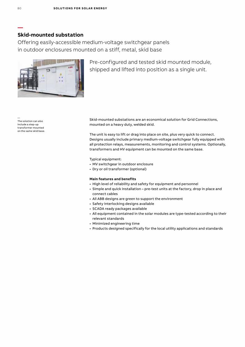
Skid-mounted substations are an economical solution for Grid Connections, mounted on a heavy duty, welded skid.
The unit is easy to lift or drag into place on site, plus very quick to connect.Designs usually include primary medium-voltage switchgear fully equipped with all protection relays, measurements, monitoring and control systems. Optionally, transformers and HV equipment can be mounted on the same base.
Typical equipment: • MV switchgear in outdoor enclosure• Dry or oil transformer (optional)
Main features and benefits• High level of reliability and safety for equipment and personnel• Simple and quick installation – pre-test units at the factory, drop in place and
connect cables• All ABB designs are green to support the environment• Safety interlocking designs available• SCADA ready packages available• All equipment contained in the solar modules are type-tested according to their
relevant standards• Minimized engineering time• Products designed specifically for the local utility applications and standards
—The solution can also include a step-up transformer mounted on the same skid base.
—
Pre-configured and tested skid mounted module, shipped and lifted into position as a single unit.
—Skid-mounted substationOffering easily-accessible medium-voltage switchgear panels in outdoor enclosures mounted on a stiff, metal, skid base
80 S O LUTI O N S FO R S O L A R E N E RGY

—UniGearIndoor medium-voltage air-insulated switchgear and motor control centers for primary distribution
The UniGear product family of IEC switchgear and motor control centers for primary distribution allow you to freely combine different types of panels(UniGear ZS1, UniGear 550, UniGear 500R and UniGear MCC) in the same switchgear, giving the highest flexibility while optimizing footprint.
Main features and benefits• Proven air-insulated primary switchgear up to 40.5kV, 50kA• Ensure highest flexibility while optimizing footprint• Freely combine different types of panels in the same switchgear• Easy to install, maintain and simple to extend• High flexibility and high seismic vibration endurance
ABB Ability™ AIS for MV - UniGear is an advanced switchgear solution to meet the requirements of the future. It is based on the well-proven UniGear product family of switchgears and provides unprecedented flexibility, increased process efficiency, lower cost of operation and maximized integration, reliability and safety.
UniGear Digital is accomplished by providing state-of-the-art, well-proven components such as current and voltage sensors, intelligent electronic devicesfor protection and control, and IEC 61850 digital communication.
Main features and benefits• Innovative solution based on the proven UniGear product family• Full advantage of ABB’s Relion® protection relays, IEC 61850 communication and
sensor technology• Safe and reliable with fewer live parts and insulating components• Extended communication supervision functionality• Simple and efficient with 30% faster delivery time • Easier installation, commissioning and testing• Ready for the future and smart grids with IEC 61850 communication protocol
and easy switchboard extension and integration• Lower environmental impact with reduced energy consumption and switchgear
footprint
—UniGear DigitalAn innovative digital solution for medium-voltage air-insulated switchgear
81

SafeRing is a ring main unit (RMU) for secondary distribution networks. It is available in 10 standard configurations suitable for most switching applications up to 40,5kV.
SafePlus is a metal enclosed compact switchgear system for distribution applications up to 40,5kV. The switchgear offers unique flexibility thanks to its extendibility and the possible combination of fully modular and semi-modular configurations. Both SafeRing and SafePlus are from the same product family and have an identical user interface.
ABB also offers a climate-friendly alternative with AirPlus to end users with a green focus - keeping the same compact switchgear dimensions, safety and reliability. With AirPlus the global warming potential of the insulation gas is reduced to less than 1 - a reduction of more than 99.99% compared to SF6. The new AirPlus insulation gas is available in proven, safe and reliable switchgear design: ZX2 AirPlus for primary distribution and SafeRing AirPlus for secondary distribution.
Main features and benefits• A wide range of functional units, easy to extend and upgrade• Fully sealed for life time: designed and tested according to IEC standard• Compact dimensions and small footprint• High reliability and safety: arc suppressing and safe, easy for operators in both
maintenance and operating conditions • No live parts exposed: all operations are carried out from the front of the
switchgear• Eco-efficient alternatives with AirPlus™ or dry air as insulation gas available
—SafeRing / SafePlus / SafeRing AirPlusTM Compact medium-voltage gas-insulated ring main units and switchgear for secondary distribution
UniSec is an indoor air-insulated switchgear for medium-voltage secondary distribution. It is suitable, according to maximum ratings and available technical solutions, for many of applications, ie substations, utilities, commercial and residential buildings, smart grids, grid with distributed generation, hospitals, renewable (solar, wind, small hydropower), marine and transportation.
Main features and benefits• Air-insulated switchgear for secondary distribution up to 24 kV• Highly flexible, modular concept that can be readily configured to meet specific
application needs• High number of mechanical operations to allow frequent operations
—UniSecIndoor medium-voltage air-insulated switchgear for secondary distribution
82 S O LUTI O N S FO R S O L A R E N E RGY

Protection for synchronous generators as well as interconnection protection for distributed generation units.
ABB Relion protection and control REG615 is a dedicated generator and interconnection protection relay for protection, control, measurement and supervision of power generators and interconnection points of distributed generation units in utility and industrial power distribution systems. The main protection functionality includes generator differential protection, out-of-step protection and 100% stator earth-fault protection.
Main features and benefits• Withdrawable plug-in unit design for swift installation and testing• Extensive range of protection functionality for both synchronous generators
and inter connection points of distributed generation units• Ready-made standard configurations for fast and easy setup with tailoring
capabilities• Extensive generator protection with 100% stator earthfault, generator
differential and out-of-step protection• Advanced interconnection protection fulfilling the latest grid codes for higher
grid stability and reliability• IEC 61850 Edition 2 and Edition 1 support, including HSR and PRP, GOOSE
messaging and IEC 61850-9-2 LE for less wiring and supervised communication• IEEE 1588 V2 for high-accuracy time synchronization and maximum benefit of
substation-level Ethernet communication• Large graphical display for showing customizable SLDs, accessible either locally
or through a web browser-based HMI
—Relion® generator protection REG615Compact generator and extensive interconnection protection for power generation
83

Three phase reclosers up to 38 kV, 16 kA and 1250 A for outdoor pole mount or substation installation.
ABB reclosers have over 15 years of proven field performance incorporating innovative technology and unique ABB expertise, including embedded sensors with the highest accuracy and least environmental sensitivity in the market. With multiple controller options, ABB reclosers are designed to continually meet and exceed expectations supporting the growing demands of solar connection to the medium-voltage grid.
Thanks to their functionalities and flexibility, ABB’s Gridshield and OVR product lines are suitable for collection points and outdoor substations connecting solar farms to the medium-voltage grid.
Main features and benefits• Reliability – unparalleled vacuum interrupters (VI) and magnetic actuators for
full reliability and long-term performance.• Safety – no maintainable electronics in the high voltage cabinet.
Emergency trip handle.• Functionality – protection, measurements of main electrical characteristics,
synchro-check with network, connection to SCADA for remote monitoring and control.
• Unparalleled performance - HCEP (Hydrophobic Cycloaliphatic Epoxy) poles together with the highest creep distance on the market of reclosers provide the best insulation for outdoor use. Suitable for heavily polluted areas.
• Flexibility – site-ready units allowing fast installation. Easy integration with multiple controller options, including the ABB Relion family RER615 and RER620.
• Maintenance-free – state of the art VI and magnetic actuators ensure limited or no maintenance needs.
—Outdoor vacuum recloser Increase protection, reliability and flexibility of the solar plant
84 S O LUTI O N S FO R S O L A R E N E RGY

Three-phase dead tank R-MAG family has full 15, 27 and 38 kV versions with different ratings up to 3700 A and 40 kA.
ABB recognizes the industry’s focus on safety and reliability, and helps meet these goals with the R-MAG circuit breaker. Based on magnetic actuation, the R-MAG has less moving parts and is mechanically simpler than breakers with traditional spring mechanisms. The durable R-MAG design and low maintenance requirements have been consistently tested over the past 10 years in over 10,000 installations.
By employing magnetic actuation and reducing the number of moving parts, R-MAG breakers reduce the potential for safety incidents by eliminating maintenance on mechanically charged components, coils, and motors which can result in injuries to field personnel.
Magnetic actuator• No maintenance required• Reduced operations and maintenance costs• Few moving parts and consequent spare parts required
ABB vacuum interrupter• Long electrical life with proven ABB vacuum interrupters that utilize the
excellent arc quenching and insulating properties of ABB vacuum technology• Maintenance-free for life
Maintenance• 2,000 operations between servicing, four times ANSI requirements• No maintenance required on operating mechanism• No gas SF6 or oil is required to guarantee the insulation
Main features and benefits• Compatible with all forms for overcurrent, reclosing, and control functions • Reduced maintenance with magnetic actuator and easy plug and play actuator
circuitry• Durable design exceeds ANSI C37.06 standard with a rating of 10,000
mechanical or load operations• 15/27/38 kV rating classes and up to 3,700 A continuous current • Up to 40 kA short circuit interrupting current
—R-MAG outdoor vacuum circuit breaker Combines vacuum interrupter technology with magnetic actuation for unparalleled reliability and operator safety
85

Three-phase live tank circuit breakers up to 40.5 kV, 31.5 kA and 2,500 A for outdoor substation installation.
In the live tank design the vacuum interrupters are housed in hollow porcelain insulators filled with Nitrogen gas to safeguard against condensation. A spring-operated mechanism is housed in a weather-proof cabinet and a sturdy extruded steel angle structure is used for mounting the breaker.
ABB OVB-VBF circuit breakers are used for solar applications, mainly in outdoor substations connecting the plant to the medium-voltage grid.
Main features and benefits• Designed and type tested as per IEC 62271-100• Porcelain-clad construction suitable for outdoor substation ensures protection
from hazardous conditions• Long electrical life with proven ABB vacuum interrupters that utilize the
excellent arc quenching and insulating properties of ABB vacuum technology• Suitable for auto-closure duty cycle of O-0.3 sec-CO-3 min-CO and
CO-15 sec-CO• Simple and reliable spring mechanism minimizes operating energy and ensures
longer mechanical life• Simple installation – structure mounted with option of extension for ie CTs• The complete breaker can be shipped as one unit with minimal adjustments to
be made on site. As an option, the breaker can be shipped in knocked-down kits which can be easily assembled at site.
—OVB-VBF outdoor vacuum circuit breaker Medium-voltage live tank circuit breaker with spring mechanism for simple site installations
86 S O LUTI O N S FO R S O L A R E N E RGY
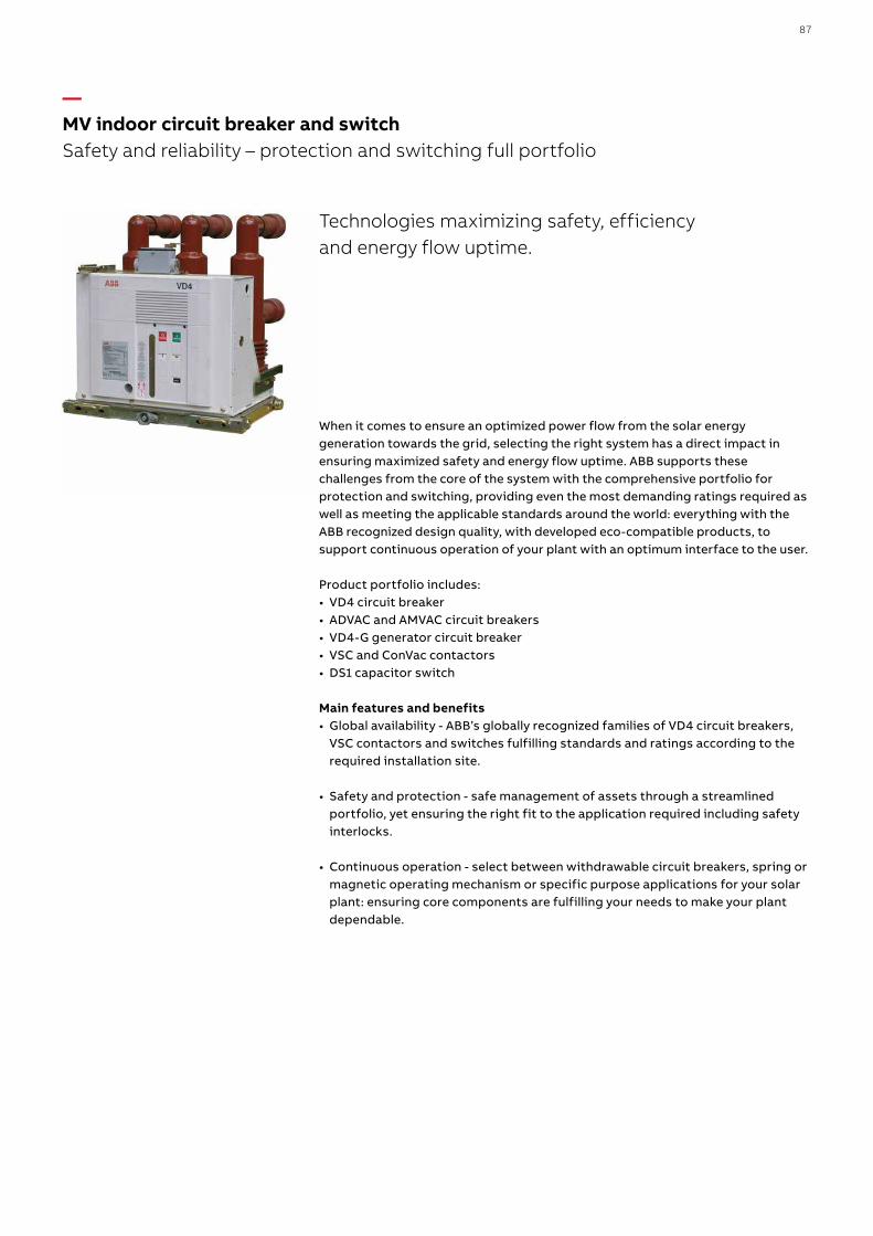
Technologies maximizing safety, efficiency and energy flow uptime.
When it comes to ensure an optimized power flow from the solar energy generation towards the grid, selecting the right system has a direct impact in ensuring maximized safety and energy flow uptime. ABB supports these challenges from the core of the system with the comprehensive portfolio for protection and switching, providing even the most demanding ratings required as well as meeting the applicable standards around the world: everything with the ABB recognized design quality, with developed eco-compatible products, to support continuous operation of your plant with an optimum interface to the user.
Product portfolio includes:• VD4 circuit breaker• ADVAC and AMVAC circuit breakers• VD4-G generator circuit breaker• VSC and ConVac contactors• DS1 capacitor switch
Main features and benefits• Global availability - ABB’s globally recognized families of VD4 circuit breakers,
VSC contactors and switches fulfilling standards and ratings according to the required installation site.
• Safety and protection - safe management of assets through a streamlined portfolio, yet ensuring the right fit to the application required including safety interlocks.
• Continuous operation - select between withdrawable circuit breakers, spring or magnetic operating mechanism or specific purpose applications for your solar plant: ensuring core components are fulfilling your needs to make your plant dependable.
—MV indoor circuit breaker and switchSafety and reliability – protection and switching full portfolio
87

The NALFWind is a high performance 36kV air insulated load break switch with integrated fast acting current limiting fuses for protection of distribution transformers in renewable installations. The fast-acting ABB CEF-S current limiting fuses provides protection on both MV and LV sides for transformers up to 3,000 kVA.
NAL/NALF are air-insulated switch-disconnectors up to 36 kV for protection of transformers and for application as line switches in medium-voltage networks. In combination with CEF current limiting fuses, they provide reliable control over the full range of overload currents. Their flexible design supports creation of customer-friendly configurations.
GSec is a three-position SF6 gas-insulated switch-disconnector designed for use in medium voltage for up to 24 kV installations. It is available with a fuse tripping system and offers easy adaptation with smart grid systems. It is a very compact product with an integrated earthing switch with making capacity.
All ABB indoor switches come with wide range of accessories for customized configurations.
Main features and benefits• Smart integration: Modular construction, compact size, easy installation,
one switch - many applications• High electrical and mechanical endurance• Full range protection against overload and short circuits current • Stringent testing of each unit, multi-standard worldwide use• Smart grid ready
—NALFWind/NAL/GSec Indoor switches and switch-fuse combinations for secondary distribution
Air and gas insulated switches, switch-disconnectors and switch-fuse combinations up to 38.5 kV for indoor operation in MV switchgear or compact substation.
88 S O LUTI O N S FO R S O L A R E N E RGY

ABB indoor instrument transformers family offers an extensive range of products for indoor applications in medium voltage systems. The instrument transformers are very flexible in parameters, dimensions and shapes and therefore they are appropriate for solar applications. ABB instrument transformers are manufactured according to the latest standard like IEC, ANSI, GB, GOST, VDE, AS and others.
Main features and benefits• For primary voltage up to 40.5 kV• For measuring and protection with up to 6 secondary windings (TPU)• Primary and secondary reconnection• Possibility of a fuse (TJP voltage transformer)• Silver coated primary terminals (TPU)• Ready for tariff metering• Over voltage factor 1.9xUn/8h as a standard (voltage transformers)• Split core types• Possibility of KOKM with secondary current 0.075 A suitable for relay connection• Ring core current transformers with up to 12 ratios
—Instrument transformers for indoor application
Current and voltage measurements from 0.6 kV to 40,5 kV for the protection, metering and monitoring of medium voltage power systems in solar plants
89

ABB sensors offer a state-of-the-art solution providing the current and voltage signals needed for the protection and measurement of medium voltage power systems. Current and voltage sensors bring remarkable progress in measurement for medium voltage applications and open up numerous advantages and benefits in solar power plants.
Main features and benefits• For primary voltage up to 40.5 kV• High accuracy class up to 0.5• Ferromagnetic cores are non-saturable• Delivered with secondary cable and RJ45 connector• No ferroresonace for voltage and combined sensor• Solution with Rogowski coil, resistive divider and capacitive divider• Very light weight, easy and fast installation• Design optimized for application with quick delivery time• Minimize costs during operation• No need to use VT fuses
—Sensors for indoor application
Solutions for measuring currents and voltages for protection, metering and monitoring in medium voltage power systems in solar plant
90 S O LUTI O N S FO R S O L A R E N E RGY

—Smart Asset Management solutions for MV networks
MaintenancePreventive maintenance is performed after set periods of time or according to prescribed criteria.Risk-based maintenance is performed by integrating analysis, measurement and periodic on site test activities with standard preventive maintenance.Condition-based maintenance is based on monitoring the equipment performance and operating parameters, and control of the corrective actions taken.
Main features and benefits• Reduce risk of failure and performance degradation of equipment• Extend useful life of assets and guarantee high levels of plant reliability,
safety and efficiency.• Minimize occurrence of serious faults and optimize utilization of available
economic resources
— ABB provides service for the various phasesin the operation and life cycle of solar applications
Our expertise –your success
Lifecyclemanagement
Performance improvement
Rapidresponse
Operational excellence
End-of-life services
Technical support and repairs
Training Replacement
Advancedservices
Spares and consumables
Engineering and consulting
Maintenance
Installation and commissioning
Extensions,upgrades
and retrofits
Careagreements
91

ABB Ability™ Asset health for Electrical systems - MyRemoteCareMyRemoteCare is an online remote monitoring system enabling a condition-based maintenance approach for your electrification assets.
Main features and benefits• Predicts failures within your assets before they occur preventing costly
downtime and repairs• Allows for optimized maintenance strategy and spending• Helps to extend the lifetime of assets and to maximize investment• Fleet-oriented remote web interface for operators• Alerts by mail• Periodic summary reports
ABB Ability™ Condition monitoring for Breakers - MySiteCareMySiteCare collects field data of circuit breaker and switchgear and directly provides local diagnostic information. The unit can also send the collected data to MyRemoteCare.
Main features and benefits• Assists in predicting failures within your assets before they occur preventing
costly downtime and repairs.• Allows for optimized maintenance strategy and spending• Retrieving data. Wait a few seconds and try to cut or copy again.• Asset-oriented local interface for operators• Circuit breaker condition monitoring• Switchgear condition monitoring
—Smart Asset Management solutions for medium-voltage networks
92 S O LUTI O N S FO R S O L A R E N E RGY

ABB Ability™ Life cycle assessment for Electrical systems –MySiteConditionMySiteCondition is a solution for asset condition and risk assessment of your low and medium voltage switchgear and transformers regardless of age or manufacturer.
Main features and benefits• Condition status, objective up-to-date overview of the substation and the
condition of each single component• Risk reduction, knowledge about the risk reduction opportunities as well as
recommended mitigation actions• Budget allocation, operational budget only used where asset reliability or safety
might be endangered in the future• Off-line fleet management solution• Basic assessment for a quick survey of the live equipment• Deep assessment for a full survey of the de-energized equipment
93

— Solar energy Other products
94 S O LUTI O N S FO R S O L A R E N E RGY

95

With a voltage rating up to 1500V DC IEC and 1500V DC UL, ABB‘s MC4-EVO2 PV connectors can be installed in any environment including commercial, industrial and residential rooftop PV installations.
They enable to connect the DC circuits from the inverter to the PV modules, in compliance with the standards IEC 62852:2014 and UL 6703.
Their housing is made in impact-resistant polyamide and can withstand UV radiation, salt spray and ammonia vapors. They are fully compatible with MC4-type PV connectors.
PV module
Combiner box
11
1. Plug connector2. Panel receptacle3. Branch connector
13
3
1 1 2
2
—Connection devicesPV connectors
— Plug connector
Ø insulation section Section Female Male
4.7-6.1 mm 4-6 mm² 12-10 AWG
1500V DC (IEC) 1500V DC (UL)
PV-PLUG-F6/6.1 PV-PLUG-M6/6.1
6.1-7.6 mm 4-6 mm² 12-10 AWG PV-PLUG-F6/7.6 PV-PLUG-M6/7.6
7.6-8.5 mm 4-6 mm² 12-10 AWG PV-PLUG-F6/8.5 PV-PLUG-M6/8.5
7.6-8.5 mm 10 mm² 8 AWG PV-PLUG-F10/8.5 PV-PLUG-M10/8.5
— Panel receptacle
Section Female Male
4.6 mm2 12-10 AWG
1250V DC (IEC*) 1000V DC (UL)
PV-RECEP-F6 PV-RECEP-M6
10 mm2 12-10 AWG PV-RECEP-F10 PV-RECEP-M10 *MC4-EVO2 version (1500V DC IEC and 1500V DC UL) available at the end of 2016
— Branch connector
In / Out Female Male
2 females / 1 male
1000V DC (IEC) 1500V DC (UL)
PV-BRANCH-F -
2 males / 1 female - PV-BRANCH-M
96 S O LUTI O N S FO R S O L A R E N E RGY

NPG, Quick Connect™ allows fast and effective fitting of cable glands without access to the inside of an enclosure, allowing fast installation:• Single Piece (No locknut required)• Corrosion resistant• Operating temperature range: -20....+100ºC• Halogen free construction available in Black, Grey and Light Grey• UL514B / CSA C22.2 No 18.3 • EN 62444• RoHS 2011/65/EU Incorporating 2015/863 amendment to Annex II• WEEE 2002/96/EC• LVD (Low Voltage Directive) 2014/35/EU
ABB offers one of the industry’s broadest range of innovative solutions for bundling, securing and routing wires and cables, including the trusted original Ty-Rap®, Ty-Met™ and Deltec fastening products and tools.• Ty-Rap's smooth, notchless body reduces the number of stress points to
increase its useful life, while ribs and stipples grip the bundle and prevent slipping specifically in vibrating applications
• The Grip of Steel®: Ty-Rap's non-hydroscopic stainless steel locking device ensures maximum strength and extended useful life
• Also available in heat stabilised + UV-resistant version, for outdoor applications that also require a resistance to high temperature (+105 °C).
• Several lengths and 6 typical widths with a tensile strength up to 780N, to cover the most demanding applications
• Packaging: OEM bulk quantities in recyclable polythene bags• Also available in small bags with Euroslot and in workbench boxes• Deltec fastening to secure and hold solar panels in place, designed to perform a
minimum of 20 years outdoors
Main technical specifications Cable ties
Material - Moulding polyamide 6.6 and polyamide 12
Material - Locking barb 316 grade stainless steel
Temperature range -40°C to +85°C
Colour black
Flammability rating UL 94 V-2
Other properties UV-resistant, Halogen free, Silicone free
—ABB Quick connect cable glands
—ABB Ty-Rap and Deltec cable ties
97

offers a broad product portfolio of cable protection products.
Our 30 years’ experience in the design and production of cable protection systems guarantees optimal solutions for use in power generation applications whether they are driven by water, wind, sunlight or gas.
Comprehensive selection fittings:• Protection degree: IP66 / IP68 and IP69K• Metric, NPT and PG threads made of metal and plastic• Available with strain relief elements• Compatible with all leading component manufacturers• EMC fittings in the standard range• Junction pieces available from stock
Comprehensive selection conduits:• Continuous operating temperature: –100 °C to +200 °C• Both for internal and external use• Excellent UV resistance• Resistant to high dynamic loading• Extremely high compression strength• Electro-statically discharging materials• Nominal diameters: 07 to 125• Closed and divisible conduits types• Free from halogens, REACH + ROHS compliant
Comprehensive selection of accessories:• Various support systems for all requirements• Connection and branching parts available
All products are rigorously tried and tested to meet the demands of industry worldwide:
—Cable Protection System Solutions
98 S O LUTI O N S FO R S O L A R E N E RGY

ABB has a complete range of pilot devices; emergency stops, pilot lights, push buttons and selector switches. Two ranges are available; the Modular range for flexibility and quick assembly and the Compact range for high quality at low cost by ”all-in-one” design. Both ranges are with high ratings.Compact range offers high degree of protection with IP67/IP69K.
Main technical specifications Pilot devices
Hole diameter 22 mm (30 mm adaptors available)
Contacts 690 V, 10 A, wiping action Low energy block
(gold plated or micro switch) available
Colours Red, Green, Yellow, Blue, White, Black, Clear
Customized marking avilable Yes (“L-mark” system)
Enclosures Plastic or metallic. Separate enclosures or complete
assembled stations
Reference standardsIEC60947 (general)
IEC60947-5-5 (emergency stops)
ABB could offer a wide and complete range of ERC products for any kind of use: • Electronic timers provide timing functions for all applications• Measuring and monitoring relays to measure voltage, current, temperature,
isolation and more• High efficient switch mode power supplies for single and three-phase applications• Signal converters for analog signal conversion and isolation and for serial data
transmission• Interface Relays and Optocouplers in pluggable and compact version for multi
purpose usage in all kind of control applications
—Pilot Devices Modular or Compact ranges
—Electronic Relays and Controls (ERC)
99

To provide efficient protection for a Solar system, the solar plant must be protected against direct lightning strikes and have a proper grounding system in addition to protection against overvoltage on both side of the inverter.ABB offers:
• OPR, ESE lightning rod protect against direct lightning• Simple rod lightning protection against direct lightning• Earthing and interconnection system to safely dissipate the lightning current• New Rodcheck system as visual strike indicator.
Main technical specifications OPR
Lightning current withstand (10/350µs) kA 100
Gain in Sparkover Time us 30 / 45 / 60
EMC Interferences measurements / Interferences immunity
EN 50 081.1 / EN 50 082.2 / NFC17102
—Direct lightning protection OPR, simple rod and earthing system
100 S O LUTI O N S FO R S O L A R E N E RGY


102
Additional informationWe reserve the right to make technical changes or modify the contents of this document without prior notice. With regard to purchase orders, the agreed particulars shall prevail. ABB AG does not accept any responsibility whatso-ever for potential errors or possible lack of information in this document.
We reserve all rights in this document and in the subject matter and illustra-tions contained therein. Any reproduc-tion, disclosure to third parties or utilization of its contents – in whole or in parts – is forbidden without prior written consent of ABB AG.

103

—abb.com/solar
1SD
C0
073
51B
020
2 - 0
6.2
018
© Copyright 2018 ABB. All rights reserved. Specifications subject to change without notice.