solutions of a simple beam deflection problem using a...
TRANSCRIPT

Solutions of a simple beam deflection problem using a variety of methods.
W = 20 lb/in
L = 40”
The beam is made from G10200 steel and has a rectangular section, 2” high and 1” thick. Young’s Modulus E = 30 Mpsi.
1. Solution by discontinuity functions.
w M1
R2 R1
M(x) = -M1<x-0>0 + R1<x-0>1 - w<x-0>2/2 EIv” = M1<x-0>0 - R1<x-0>1 + w<x-0>2/2 EIv’ = M1<x-0>1 - R1<x-0>2/2 + w<x-0>3/6 + C1
EIv = M1<x-0>2/2 - R1<x-0>3/6 + w<x-0>4/24 + C1x + C 2 Since v(0) = 0 and v’(0) = 0, we get C1 = C2 =0 From statics: Σ(Fy) = wL – R1 – R2 = 0 and Σ(M) = -M1 + wL2/2 – R2L = 0 From v(L) = 0 we get M1L2/2 – R1L3/6 + wL4/24 =0 Solving these 3 equations and using L = 40 in and w = 20 lb/in we get, R1 = 500 lb, R2 = 300 lb and M1 = 4000 lb-in. Use EIv’ = 0 to find the point of maximum deflection: 4000 x - 250 x2 + 20x3/6 = 0 which yields x = 23.1386 in. E = 30x106 and I = 1x23/12 = 0.6667 in4
This gives a maximum deflection δx = 0.01385 in. at x = 23.1386 in
Solutions of a simple beam deflection problem using a variety of methods.
From the shear force diagram, we find V = 0 at x =25” and, thus the
maximum bending moment is 2250 in-lb at x=25” . However, the bending moment at the fixed end is 4000 in-lb and is thus the maximum moment.
The maximum bending stress is Mc/I = 4000x6/22 = 6000 psi at the
fixed end. At x = 25”, the stress is 3375 psi.
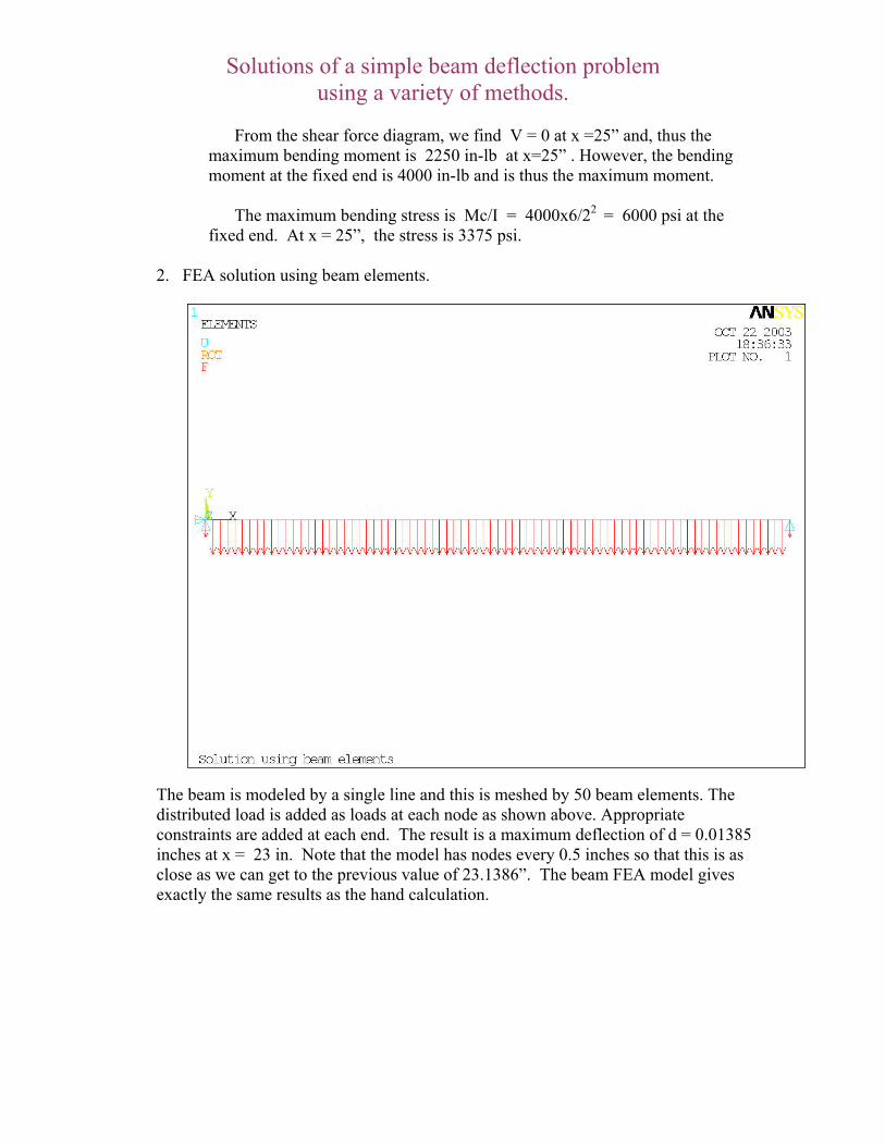
2. FEA solution using beam elements.
The beam is modeled by a single line and this is meshed by 50 beam elements. The distributed load is added as loads at each node as shown above. Appropriate constraints are added at each end. The result is a maximum deflection of d = 0.01385 inches at x = 23 in. Note that the model has nodes every 0.5 inches so that this is as close as we can get to the previous value of 23.1386”. The beam FEA model gives exactly the same results as the hand calculation.

Solutions of a simple beam deflection problem using a variety of methods.
3. Detailed solution of a more realistic beam using FEA with solid brick elements.

Solutions of a simple beam deflection problem using a variety of methods.
The actual geometry of the beam is modeled along its length. At 0.25” radius fillet is added at the fixed end and the support is represented by a large steel block to which the beam is attached. This block is then constrained to not move under load. The far end of the beam is constrained only in the y-direction. A pressure load of 20 psi is applied to the top surface of the beam. The deflection solution is shown below.
The maximum deflection is 0.01461 in. at x = 22.678” . This represents a 5.5% increase over the other solutions. Why should this be? (see below for further discussion).
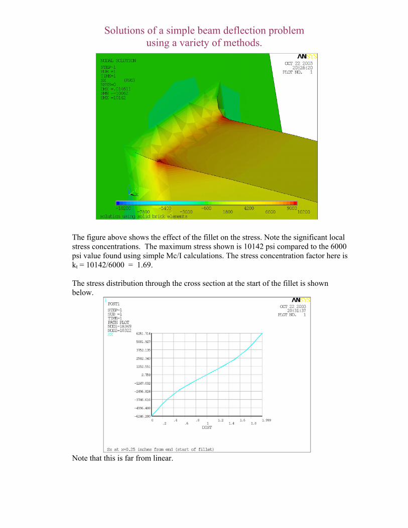
The stress in the beam is shown below:
Solutions of a simple beam deflection problem using a variety of methods.
The figure above shows the effect of the fillet on the stress. Note the significant local stress concentrations. The maximum stress shown is 10142 psi compared to the 6000 psi value found using simple Mc/I calculations. The stress concentration factor here is kt = 10142/6000 = 1.69. The stress distribution through the cross section at the start of the fillet is shown below. Note that this is far from linear.
Solutions of a simple beam deflection problem using a variety of methods.
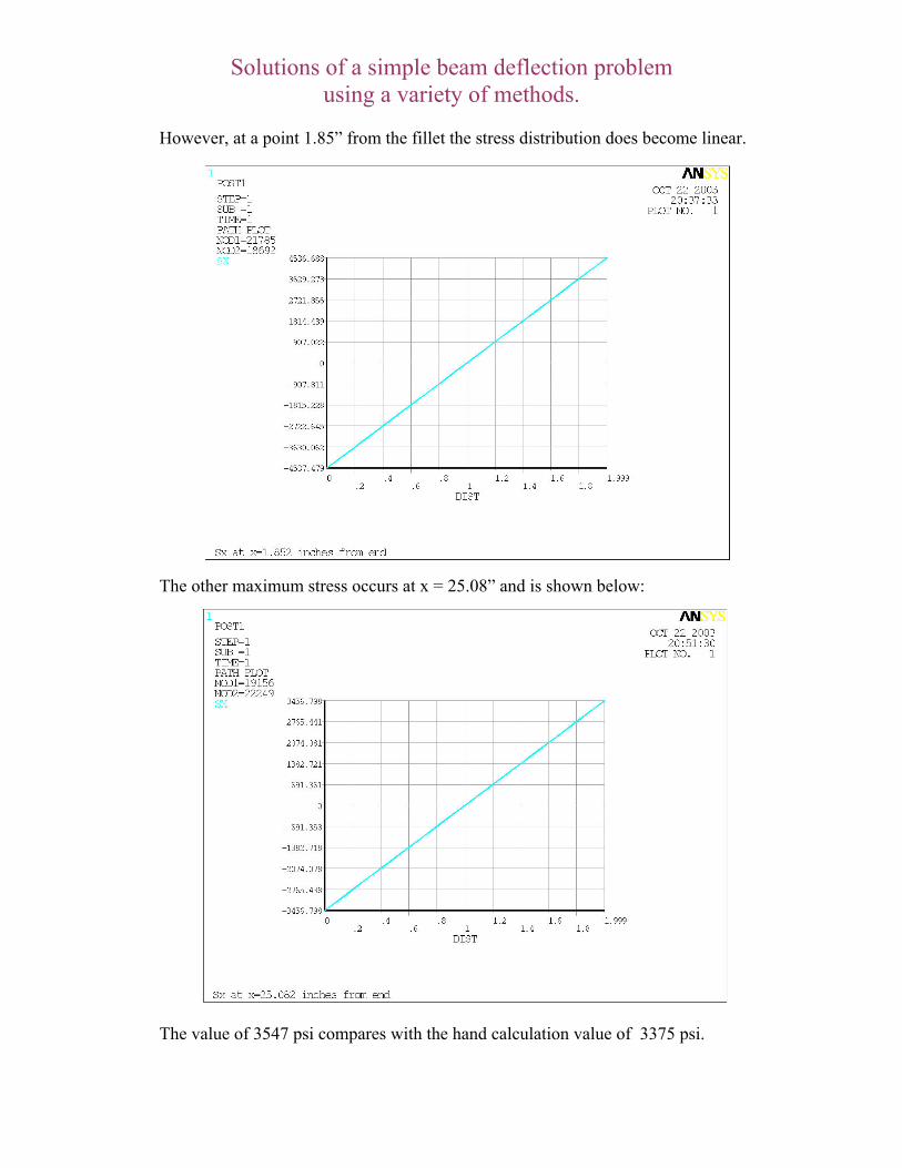
However, at a point 1.85” from the fillet the stress distribution does become linear. The other maximum stress occurs at x = 25.08” and is shown below: The value of 3547 psi compares with the hand calculation value of 3375 psi.

Solutions of a simple beam deflection problem using a variety of methods.
Why the different results from the 3-d FEA? One possible answer is that we have ignored shear deflections in the beam FEA model and in the hand calculation but not in the 3-d FEA model. We can add shear stiffness to the beam FEA model: The maximum deflection is now 0.014091”, much closer to the value of 0.01461” found in the 3-d FEA model, the difference now being 3.6% The other possible answer is the difference in the fixed end support conditions. In the 3-d model this condition is more realistic as there is really no such thing as a truly fixed end. If the support block is removed and an actual fixed condition is applied to the end of the beam, the maximum deflection becomes 0.014062” giving an overall difference of 0.2% between the beam model and the 3-d model.

Solutions of a simple beam deflection problem using a variety of methods.
In conclusion we see that, in this example, the shear deflection adds about 2% to the deflection value. Even the very substantial end support block used in the 3-d model still allows about a 3.4% increase in the deflection.