solutions to field problems of a gas turbine-axial …
TRANSCRIPT
SOLUTIONS TO FIELD PROBLEMS OF A GAS TURBINE-AXIAL FLOW CHEMICAL PROCESS COMPRESSOR TRAIN BASED ON COMPUTER SIMULATION OF THE PROCESS
by' Francisco J. Gonzalez
Rotating Equipment Engineer
Enterprise Products OP
Mont Belvieu, Texas
and Meherwan P. Boyce
Managing Partner
The Boyce Consultancy
Houston, Texas
Francisco J. Gonzalez is Rotating Equipment Engineer with Enterprise Products OP, in Mont Belvieu, Texas. He has been with Enterprise since 1996, but has been working with rotating equipment since 1990. His career with rotating equipment originated at Amoco Chemical, where he held positions as Project, Maintenance, and Reliability Engineer. Mr. Gonzalez's current responsibilities are to provide technical support to operations and
maintenance for rotating equipment. This includes rotating equipment vibration monitoring, aerothermal performance monitoring, troubleshooting, overhaul, performance testing, and gas turbine and centrifugal compressor optimization. Other activities include monitoring, optimizing, and troubleshooting compressor surge controllers and turbine controls. He is also responsible for evaluating and implementing short-term and longterm reliability improvements for all rotating equipment. Enterprise Products currently operates 37 small industrial gas turbines (4000 hp to 15,000 hp) in chemical, refrigeration, and pipeline services.
Mr. Gonzalez has a B. S. degree (Mechanical Engineering, 1990) from the University of Houston.
Meherwan P. Boyce is Managing Partner of The Boyce Consultancy, in Houston, Texas. He has over 35 years of experience in the turbomachinery field. He was chairman and CEO of Boyce Engineering international and the pioneer of online condition-based performance monitoring. He has developed models for various types of power plants and petrochemical complexes. His experience includes Director and Founder of the Turbomachinery Laboratories, where he
also Founded and was Chairman of the Turbomachinery Symposium. He is an author of the "Gas Turbine Engineering Handbook. "
Dr. Boyce received B. S. and M. S. degrees (Mechanical Engineering) from the South Dakota School of Mines and Technology (1962) and the State University of New York (1964), respectively, and a Ph.D. degree (Aerospace and Mechanical Engineering) from the University of Oklahoma (1969). He is a Fellow of ASME, a member of SAE and NSPE, and is a registered Professional Engineer in the State of Texas.
77
ABSTRACT Operating and maintaining key rotating equipment in a
petrochemical service with tight economic constraints requires an indepth evaluation in performance deterioration of key gas turbines and axial flow compressor parameters .
By upgrading the required instrumentation o n a gas turbine and an axial flow compressor, an indepth performance simulation and evaluation can be made in order to determine the overall thermodynamic performance and mechanical deterioration of the train. With the proper instrumentation, critical parameters in the gas turbine such as component efficiencies, power, head, turbine firing temperature, heat rate, and heat balance can be computed. On the axial flow compressor, section efficiencies, head, power, flow, and head coefficients can be computed. By understanding all the performance parameters and obtaining a good running history on these parameters, one can easily determine the condition of the rotating equipment at any given time. B ased on these results, operation and maintenance techniques can be instituted.
Major rotating equipment overhaul intervals can be identified by closely monitoring the performed deterioration parameters of any gas turbine or axial flow compressor. This enables the unit to be operated with confidence through a planned major overhaul. On a separate occasion, a costly emergency shutdown was avoided by constantly monitoring the mechanical and thermodynamic performance of the compressor train until operations created an outage time. The outage time was based on preparation to minimize the downtime, as well as take into consideration product delivery schedules.
Detail analysis of the gas turbine and axial flow compressor train computer simulation is presented to enable the reader to fully evaluate their own compressor train under various operating parameters such as molecular weight, speed, and varying inlet conditions, both process as well as ambient.
INTRODUCTION The paper deals with an industrial gas turbine driving an axial
flow process compressor in a petrochemical plant. The gas turbine power needed to drive the compressor is limited at temperatures exceeding 70'F. This leads to surge problems in the process axial flow compressor.
Equipment Description
The train consists of a gas turbine and an axial flow compressor. The unit operates as a critical component of the methyl tertiary-butyl ether (MTBE) unit at the Enterprise Production Company, Mont Bellvieu, Texas.
78 PROCEEDINGS OF THE 28TH TURBOMACHINERY SYMPOSIUM
Figure 1 is a schematic of the turbine-compressor train. The schematic shows that the gas turbine at the turbine inlet has an evaporator to reduce the temperature at the turbine inlet. The exhaust gases are used for various processes and this leads to an increased backpressure on the gas turbine.
Figure 1. Schematic of Turbine Compressor Train.
The presently installed gas turbine is rated at 1 5,5?0 hp at .I�O conditions ( 1 4.7 psia, 60'F, and 60 percent relative hurmdity (RH)), with no intake and exhaust losses, and operation at design speeds for both the gasifier and power turbines (GT = 1 0,780 rpm and PT = 9500 rpm). The unit has a 1 7 -stage axial flow compressor with a design pressure ratio of 1 7: 1, which is driven by a two-stage axial flow gasifier turbine. The power turbine is also a two-stage axial flow turbine operating on a separate shaft, which is coupled to an axial flow compressor.
The axial flow compressor is a two-section unit with stages one to eight comprising section one and stages nine to 1 5 comprising section two, as seen in Figure 2. The unit is designed to operate on a gas of 29. 1 7 MW at inlet conditions of P = 1 6.2 psia and T = 1 08.6'F. The design flow for the unit is M = 336,674 lbm/hr with a polytropic head = 67,000 ft-lbfllbm, and a power �equirer,nent of 14,000 hp. The unit produces an overall Pr = 7.34, wtth sectio� one having a Pr = 3.54 and section two with a Pr = 2.07. The umt has a low-pressure and high-pressure recirculation surge contr?l valve. The low-pressure valve recirculates the flow around section one, and the high-pressure valve recirculates the flow from the exhaust to the compressor intake.
Figure 2. Process Axial Flow Compressor Rotor.
Operating Conditions
Currently, the axial compressor operates at a suction pressure that varies with the available power from 1 6.0 psia to 1 8.0 psia. The suction temperature varies a lot due to the suction fin fan coolers. The suction temperature varies between 1 00'F and 1 25'F. The discharge pressure of the axial compressor varies between 1 1 5 psia and 1 23 psia. The discharge temperature depends on the suction temperature, and varies between 300'F and 3 1 0'F.
The gas turbine operates close to sea-level conditions. The turbine inlet temperature varies with atmospheric conditions, and varies between 45'F to 80'F throughout the year. The turbine exhaust is funneled to a heat recovery unit where additional heat recovery is utilized by heating a hot oil system. The firing temperature of 2050'F is regulated by the power turbine inlet temperature, which is limited to 1325'F. In its present configuration, the unit operates at a power turbine speed of 7000 rpm, which is about 75 percent of the design speed. The turbine inlet duct pressure drop is around 5 .0 inch H20 and 1 1 inch H20 for the exhaust duct system. In the turbine inlet, there is an evaporative cooler, which results in lowering the turbine inlet temperatures when the relative humidity is low. An onlipe waterwash system is also used. Currently, the turbine is water-washed three times a week with demineralized water.
Equipment History
The present gas turbine and the present driven axial fl�w compressor have been operating since February 1 998. Before thts, the same make and manufacturer of both the gas turbine and the axial flow compressor had been operating in its present configuration since March 1 996. The process axial compressor has always experienced a short fall in turbine power due to a mismatch in gas turbine size, due to high ambient temperatures (above 70'F). Also, the lack of power is aggravated by normal fouling of the gas turbine and the process axial flow compressor.
The compressor train encounters a problem of insufficient power when ambient temperatures reach 70'F. A new exchange gas turbine was installed in February 1 998. The new gas turbine was tested at the manufacturer's facilities prior to field installation. The previously installed train had undergone several serious surge events on January 1 , 1 998 . These surge events created major thrust reversals that resulted in axial movements of over 5 mils, with corresponding thrust bearing metal temperature increases of 20'F and radial bearing vibration magnitude increases of four to five times the presurge levels. These events caused damage . to . the driven axial flow compressor, which then, after careful momtonng, was brought down to have the rotor replaced. At the same time, it was decided the gas turbine should be replaced, since the unit was "seemingly" not producing the energy required and since it was close to the 25,000 hr exchange schedule.
Testing of the old gas turbine at the site just before removal, and further testing of the gas turbine after removal at the manufacturers test facility in January 1 998, did not reveal any significant deterioration in performance when compared with the test results of March 1 996. The reason for having this test was to obtain a correlation of the various parameters in the field to those in the test stand. This is especially true for the lower operational speed of the power turbine and its correlation to the turbine firing temperature. The importance of these correlations was to allow the full use of the range of the turbine.
The surge events, on the average, take between 45 seconds and 55 seconds, even when the unit is not tripped. During the surge mode, large force reversals are created, which place very high stresses on the unit. First, the time duration had to be reduced, and, second, the cause of the frequencies of these events investigated.
This paper deals with the studies and the factory and field tests that were conducted on this gas turbine-axial flow compressor train. It also examines the failure undergone by the driven axial flow compressor.

SOLUTIONS TO FIELD PROBLEMS OF A GAS TURBINE-AXIAL FLOW CHEMICAL
PROCESS COMPRESSOR TRAIN BASED ON COMPUTER SIMULATION OF THE PROCESS 79
Axial Compressor Instrumentation
The axial flow compressor is fully instrumented so that detail section data can be obtained. This was necessary for two major reasons : • First, the axial flow compressor can and does foul, so it is important to monitor its performance to ensure that its operation is in a stable region and operating close to its design point. Due to this fouling, especially in the inlet section, the unit has several pressure probes to ensure an accurate reading. • Second, the axial flow compressor is used to compute and correlate the power output of the gas turbine, thus its accuracy in computation of the power absorbed by the axial flow compressor.
The inlet casing is fully instrumented for determining the flow into the compressor. Intersection pressure, temperature, and flow measurements enable the performance of each section to be fully evaluated. The pressure measurements are static measurements, the temperature measurements are total, since static temperatures cannot be measured in any practical manner. With the instrumentation available, the performance deterioration on any given day can be computed. This instrumentation has been extremely helpful in identifying the associated problems with process conditions , gas turbine, and axial compressor deterioration. All the flow measurements are made with an annubar. All vibration measurements are made with displacement probes on the rotor shafts and thrust bearings. The following is a list of the instrumentation on this axial compressor: • Compressor suction static pressure • Compressor suction total temperature • Compressor intersection total temperature • Compressor intersection static pressure • Compressor discharge static pressure • Compressor discharge total temperature • Compressor suction flow differential pressure • Compressor gas specific gravity • Compressor recycle flow section two • Compressor recycle flow section one • Compressor balance piston pressure • Power turbine/compressor speed • Compressor outboard thrust bearing active metal temperature • Compressor outboard thrust bearing active axial displacement • Compressor inboard thrust bearing inactive metal temperature • Compressor inboard thrust bearing inactive axial displacement • Compressor forward y-axis radial displacement • Compressor forward x-axis radial displacement • Compressor aft x-axis radial displacement • Compressor aft y-axis radial displacement
Gas Turbine Instrumentation
The gas turbine has been fully instrumented in order to evaluate its deterioration on any given day. Most of the turbine measurement points are the same points being measured by the turbine manufacturer in their control system. By having these measurements, a direct comparison between field performance and actual shop performance data could be ascertained. The following instrumentation is available in this gas turbine: • Gasifier turbine speed • Power turbine speed
• Barometric pressure • Relative humidity • Turbine inlet filter differential pressure • Turbine inlet pressure drop • Turbine inlet temperature • Turbine compressor discharge temperature • Turbine compressor discharge pressure • Turbine T5 firing temperatures ( 1 6 thermocouples) • Turbine exhaust temperature • Turbine exhaust backpressure • Turbine fuel flow • Gas fuel temperature • Gas fuel pressure • Gas fuel flow differential pressure • Turbine bleed valve feedback • Turbine inlet guide vane feedback • Turbine bleed valve inlet temperature • Turbine bleed valve discharge temperature
PERFORMANCE COMPUTATIONS This section deals with the equations and techniques used to
compute and simulate the various performance and mechanical parameters for the gas turbine and the driven axial flow compressor. The goals have been to be able to operate the train at its maximum design efficiency and at the maximum power that can be obtained by the turbine without degrading the hot section life.
Axial Flow Process Compressor
The axial flow process compressor is a two-section unit with stages one to eight comprising section one and stages nine to 1 5 comprising section two. The unit i s directly coupled t o the gas turbine. The unit is designed to operate on a process gas of 29. 1 7 M W a t inlet conditions o f P = 1 6.2 psia, T = 1 08 .6'F, and a speed of N = 7200 rpm. The design flow for the unit is M = 336,674 lbmlhr, with a polytropic head = 67,000 ft-lbrflbm, and a power requirement of 1 4,000 hp. The unit produces an overall Pr = 7 . 34, with section one having a Pr = 3.54 and section two with a Pr = 2.07. The unit has a low-pressure and high-pressure recirculation surge control valve. The low-pressure valve recirculates the flow around section one, and the high-pressure valve recirculates the flow from the exhaust to the compressor intake.
By recording the measurements stated above, calculation of the compressor 's section and overall efficiencies, polytropic head, and horsepower are possible. The measurements taken on the compressor are static pressures and total temperatures . The existing measurements are for measuring changes in the performance and are not used for precise power calculations.
Axial Flow Process Compressor Surge Protection
This axial compressor utilizes a two-stage surge protection scheme. Figure 3 is a schematic of the compressor surge mechanism. This compressor is used in two separate operating conditions. The normal operating mode is with a mix hydrocarbon gas, but at times the operating condition is changed to a hot nitrogen strip mode during a catalyst regeneration mode. The compressor manufacturer determined that a two-stage surge protection algorithm is required in order to fully protect the compressor. The first stage surge protection controller monitors the suction conditions including the suction flow, while the second section surge controller monitors the discharge condition. Both

80 PROCEEDINGS OF THE 28TH TURBOMACIUNERY SYMPOSIUM
surge controllers use a standard proportional-plus-integral (PI) mode control. A 1 0:4 coupling ratio is implemented between the low and high stage antisurge algorithm. This is done in order to avoid surge on the second half of the compressor when the first stage controller reacts to avoid a surge.
Figure 3. Schematic Process Compressor Surge Control System.
Axial Flow Process Compressor Performance
The performance of the axial flow compressor was calculated for both sections of the process compressor. Great effort was made to ensure the accuracy of these relationships. The compressor computations are very closely entwined with the computations of the gas turbine, which was known to be insufficient in its power output at the lower than design power turbine speed.
The computations of each section as to the head developed and the flow through each section are closely monitored, as the unit is carefully steered away from the surge line. It is of great importance that the unit operates as close to its point of maximum efficiency without operating in an unstable flow region. The benefit of having a performance evaluation at any given time outweighs the expense for obtaining this type of analysis. Some of the benefits include longer operating intervals between overhauls , reduction in operating expenses, and greater operating equipment knowledge.
Gas Turbine
The gas turbine is rated at 1 5 ,500 hp at ISO conditions ( 1 4.7 psia, 6o·F, and 60 percent RH), with no intake and exhaust losses, and operation at design speeds for both the gasifier and power turbines (GT = 1 0,780 rpm and PT = 9500 rpm). The unit has a 1 7-stage axial flow compressor with a design pressure ratio of 1 7 : 1 , which is driven by a two-stage axial flow gasifier turbine. The power turbine is also a two-stage axial flow turbine operating on a separate shaft, which is coupled to the axial flow process compressor.
This gas turbine is a two-shaft turbine, and the power turbine is directly coupled to the process axial compressor. The original design requirements allowed for the power turbine speed to be slower then the usual manufacturer's optimum power turbine speed. This design requirement was implemented on the basis that the power available would be sufficient for the process requirements than the power losses generated from the off-design power turbine speed. The process compressor speed is about 25 percent less than the power turbine optimum design speed. The turbine inlet has a two-stage filter and an evaporative cooler. The turbine exit is ducted through a complex heat recovery system. This configuration causes a significant pressure drop at the inlet as well as a high backpressure. The drop in inlet pressure, the increase
in backpressure, and the reduction in speed of the power turbine leads to a significant reduction in power output from the turbine.
To properly evaluate the turbine output and to determine the deterioration, careful correction of the above-described parameters must be computed. To ensure the accuracy of the correction factors, the data were based on tests conducted on the same turbine at the manufacturer' s test stand. The tests indicated a correction of about 55 hp per inch of H20 pressure drop at the inlet, and 22 hp per inch of H20 due to the backpressure on the turbine, and about a 600 hp adjustment for about 25 percent speed decrease in the power turbine speed.
Gas Turbine Performance
The computation of the gas turbine is closely intertwined with the process axial flow compressor, since the gas turbine power is based on the power absorbed by the process compressor. The gas turbine in this application is under-powered and thus there is a lot of pressure to get every bit of power without exceeding the design firing temperature. To ensure that this i s accomplished, the turbine performance is closely monitored.
The turbine compressor efficiency and pressure ratio are closely monitored to ensure that the turbine compressor is not fouling. B ased on these computations, the turbine compressor is online water-washed three times a week with demineralized water. At times, it is necessary to adj ust the gas turbine's inlet guide vanes (IGV) in order to optimize the performance of the gas turbine axial compressor, which amounts to between 60 percent and 65 percent of the total work produced by the gas turbine.
The turbine firing temperature, which affects the life, power output, and the overall thermal efficiency of the turbine, must be calculated accurately. To ensure the accuracy of this calculation, the turbine firing temperature is computed using two techniques. These techniques are based on the fuel heat input and on the turbine heat balance. Turbine expander efficiencies are computed and deterioration noted.
The turbine is very well instrumented, as can be seen from the earlier outline of the gas turbine instrumentation. The turbine was further tested fully in the manufacturer' s facility on a dynamometer.
UNIT TRAIN FAILURE ANALYSIS Axial Compressor Failure
The axial flow compressor was damaged during the surge events , which took place in January 1 998 . The damage was mostly in section one of the unit, where it was found that the blade in the first row was broken. The unit was closely monitored by the use of performance and vibration data. It was brought down after the plant could get ready for a planned shutdown, so as to minimize downtime.
Vibration Problem
The gas turbine-process compressor train routinely had vibration spectrums taken on a weekly basis at various locations on the gas turbine and the process axial flow compressor. Following several major surge events in January 1 998 , a significant vibration level increase was observed on all bearing displacement probes, and axial shaft movement was detected. This was confirmed by substantial increase in the thrust bearing metal temperature. Spectrum surveys of the train also confirmed that the vibration levels throughout the unit had increased. The vibration signature correlated well with known rotor frequencies. At the same time the vibration levels were detected, deterioration in compressor performance was detected in the first section of the compressor. A routine vibration and performance inspection was performed several times a day, in order to closely evaluate and monitor the health of the compressor.
To fully evaluate the rotordynarnics of the compressor rotor, the first section was closely studied. It was obvious from the .

SOLUTIONS TO FIELD PROBLEMS OF A GAS TURBINE-AXIAL FLOW CHEMICAL
PROCESS COMPRESSOR TRAIN BASED ON COMPUTER SIMULATION OF THE PROCESS 81
performance data that the problem was in the first section. Table 1 shows the number of rotor and stator blades as well as the blade passing frequencies for the various stages at the process compressor operating speed of 7000 rpm.
·Table 1. Axial Flow Process Compressor Section One Blade and Vane Configuration.
Stage Rotor Blades Stator Vanes Rotor Blade Stator Vane Passing Frequency Passing Frequency
(cpm) (cpm)
IGV - 34 - 238,000 1 28 30 196,000 210,000 2 31 32 217,000 224,000 3 34 36 238,000 252,000 4 33 36 231,000 252,000 5 41 42 287,000 294,000 6 41 46 287,000 322,000 7 35 32 245,000 224,000 8 35 34 245,000 238,000
Observed in the vibration spectra were first and second order blade pass frequencies for many of the stages, and a large one-time running speed frequency. As time went on, an unknown frequency at 78,000 cpm ( 1 300 Hz) appeared in the spectra. Since this frequency was not identifiable to any known ratios, a concern was raised that it could be an individual blade resonance frequency. The frequency did not fluctuate with speed. This confinned further the suspicion that this was a blade resonance frequency. Reviewing other data, it was concluded that a significant flow disturbance was occurring in front of section one of the compressor. This instability was exciting the blade fundamental frequency.
During the month of January 1 998, the second order blade passing frequencies (2x blade passing frequency) kept increasing, which led us to believe that the process axial flow compressor's first section was reaching a surge scenario. This phenomenon of the increase of the second order blade passing frequencies has been noted in many axial flow compressors . Figure 4 shows the spectrum obtained during this period. Examining these spectra, and simultaneously noting the deterioration of the compressor's first section's perfonnance, it was concluded that, during the surge event, one or more blades in the first few stages of section one were damaged. It was decided to run the compressor until the blade resonance frequency reached .4 in/sec, and the second order blade passing frequencies were half the magnitude of the first order blade passing frequencies.
It was decided, after close examination of all the data, that the blade problem in the axial flow process compressor was very severe. This decision led to vibration and perfonnance data being closely monitored every few hours in order to evaluate the health of the gas turbine-compressor train until operations and maintenance could identify an appropriate shutdown window.
Performance Deterioration
By closely monitoring the compressor's section perfonnances and the frequency spectra, it was concluded that the problem was originating in the first eight stages of the compressor. The flow disturbance was quite evident in the frequency spectra because most of the eight first stages were observed, and the polytropic head of the first section kept dropping while the second half kept increasing.
Figure 5 shows the effect on the pressure ratio of the individual sections and the overall compressor, indicating that the unit' s section one was not performing to i t s design characteristics . The pressure ratio of the first section was considerably down and was
110. 1. 2. 3. .. 5. 6. 7. a.
llllliQ: o.oo AIIP: o OROBRI 0 . 000 DEG: --
�·r-------+--------r-------f--------r-----� ��----�-------+-------r-------�1. ----� �rr-------+--------r-------+--------r-------, �fH-------4�--------+-------+-------�------� MH-------��------���------+--------+------� �·H-------+------+-H��--�--------+-----� �·H-----�----�r+.�ll+----r------�11.1�1.----� �·H-------�--����+---�------���-----1 ��==jt�����lll�il�ll�l������li��H�I!ii�lt��
0 lilliE IIDil IIIIDI - 1111111 -����
IDllll'fiFICNZIOII OP Sl'BC'l'RAL PIWIS ABOVE THRESHOLD AIIP . llllliQ , ORDER 110. AIIP. FRIIQ.
0.7018 6937.5 0.991 9. 0.5049 266250.0 0.45J2 217125.0 31.018 10. 0.3324 U6625.0 0.4801 217500.0 31.071 11. 0.3169 273187.5 o.2561 231187.5 n.oa? 12. o.3786 2872So.o 0.2832 245250.0 35 . 036 13. 0.3027 469312.5 O.o&373 252187.5 36.027 u.. 0.3224 49068?.5 0.3636 252562.5 36.080 15. 0.2846 504750.0 0.2345 265500.0 37.929 16. 0.2245 511687.5
ORDER 38 . 036 38.089 39.027 41.036 151.045 70.098 12.107 73.098
Figure 4. Spectrum of Process Compressor Rotordynamics.
slipping lower. This is a very clear indication of damage to that section of the compressor. The overall vibration continued to increase in the inboard bearings, and some increase in vibration was also noted on the outboard bearing. Increase in the blade resonance frequency amplitude, and the amplitude of the blade passing frequency of the first few stages, also indicated problems in the first section of the process compressor.
3.40 3.20 3.00 2.80 2.80 2.40 2.20 2.00 1.80 1.60 1.40 1.20 1.00
...... COMP PR1
v
•..
...
I I � § � �
.
I I li " 5 �
-•·-COMP PR2 -+-COMP OVERALL PRES. RATIO
--,.-Y -:..._.
I . .. . ... I . ..
; ... .. . _..
I / i I I
/I v I ill I I I §I I ill I I iii iii ;; lii ;;; ., :;; iii
�
<: 5 5 5 5 ;; 5 ;; 5 §
'
1 1 1 1 1
4.0 3.0 2.0 1.0
9 0.0 t
.0 i .0 l
.o 1
.0 �
.0
8 7 6 5 4 .0 3 .0 2 .o
Figure 5. Deterioration of Process Compressor Performance after Major Surge Event.
Tear-Down Inspection
Once 'the compressor was offline, a borescope inspection was perfonned in order to do a preliminary inspection. The borescope inspection revealed extensive damage in the first several stages of the rotor and stationary blades. All necessary equipment and spare parts were identified and prepared prior to the shutdown, in order to overhaul the compressor in place if needed.
The compressor case and stationary blade carriers were split open in order to evaluate the extensive blade damage. The damage appeared to come from a foreign object that was ingested from the suction drum. Two blades in the rotor had fractured and caused extensive blade damage to the first three stages, as can be seen in Figure 6. All other stages received less damage. In total, 30 percent of the rotor and stationary blades were destroyed beyond repair.
All the j ournal and thrust bearings appeared to have a nonnal amount of wear, but overall they were in good condition, as seen in Figure 7. Both outboard and inboard dry gas seals were found in satisfactory condition.

82 PROCEEDINGS OF THE 28TH TURBOMACHINERY SYMPOSIUM
Figure 6. Blade Failure of Process Axial Flow Compressor.
Figure 7. Axial Flow Process Compressor Thrust and Journal Bearings Indicating Normal Wear but No Severe Damage.
The compressor was overhauled in place. A spare rotor assembly and a set of spare blade carriers were installed along with new seals and bearings. All fits and dimensions were checked, and no major problems were identified by the overhaul team. An outside vendor worked on the overhaul around the clock until the job was completed.
Metallurgical Analysis
An independent metallurgist performed a failure analysis. The scope of the failure analysis study was to determine the cause and mode of the blade failures, and to determine if any material properties contributed to the failure.
The independent metallurgical study concluded that a soft foreign object, which was ingested into the suction of the compressor,
caused the initial damage. As shown in the vibration trend plots, the damage occurred on January 1 , 1 998. An initial blade damage caused by the foreign object caused a stress riser to occur in the first stage blade. After operating for 1 3 days, a main section of the blade failed and consequently wiped out the third stage blade. The first stage blade did not display any signs of surface damage done by any hard metal objects. The third stage blade displayed an initial damage surface created by a metal object.
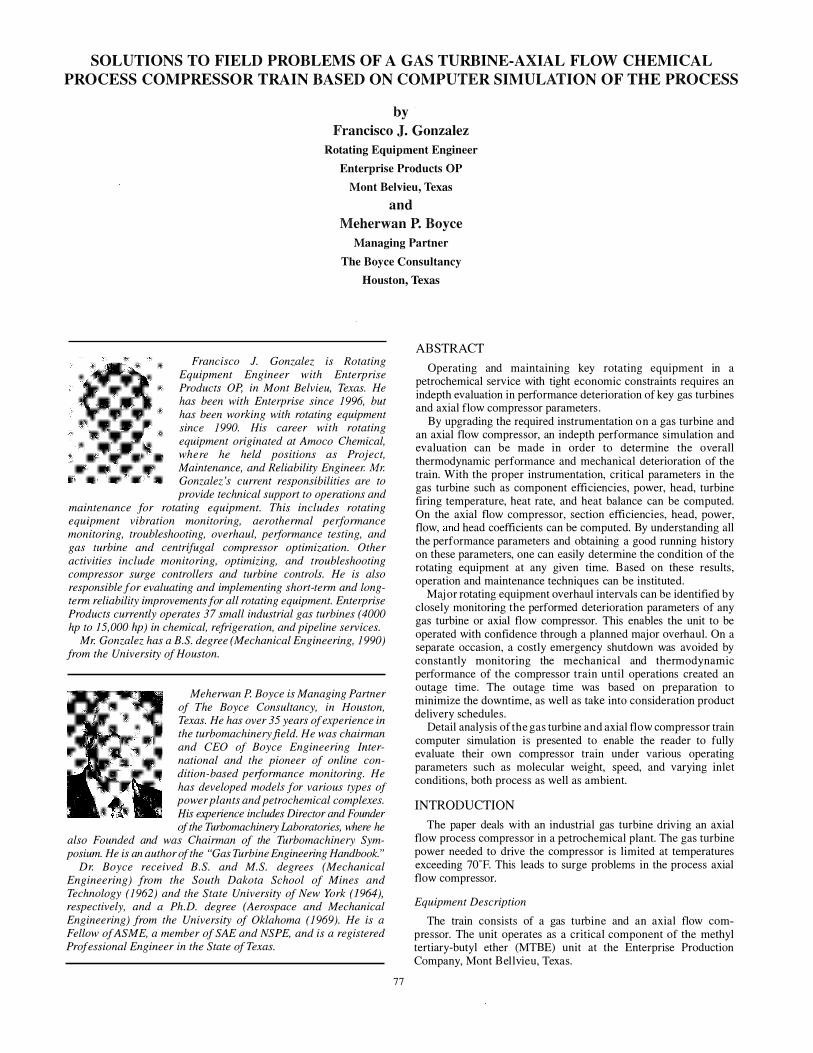
Figure 8 is a photograph of the failure of the cross section of the first stage rotor blade 28. Figure 9 is a photograph of the same blade as seen under an electron microscope. The blade was initially deflected when initial contact with the inlet guide vanes occurred during the surge event. This contact deformed the stage one blade to induce turbulent flow over the blade, resulting in a high cycle fatigue situation. This is amply illustrated in the spectrum seen in Figure 4. Subsequent damage to the rotor blades from this point indicated that, with time, the stage one, rotor blade 28, began to fatigue and fracture off in at least two, if not three, smaller pieces. This failure of the first stage blade inflicted the bulk of the damage downstream. A severe gouge was cut into the leading edge of stage three, rotor blade 27 (Figure 1 0), which served as a stress riser and an initiation point for a fatigue crack and subsequent propagation. The failure of this blade was also a fatigue failure, although some of the features were masked due to the initial contact damage. These two blades, one on the first stage and the other on the third stage within a few degrees of each other, caused severe increase in vibration over a period of time, which then led to a decision to shut down the unit.
Figure 8. Cross-Section of First Stage Blade Failure.
Figure 9. Electron Microscope View of Cross-Section of First Stage Blade.
SOLUTIONS TO FIELD PROBLEMS OF A GAS TURBINE-AXIAL FLOW CHEMICAL
PROCESS COMPRESSOR TRAIN BASED ON COMPUTER SIMULATION OF THE PROCESS 83
Figure 10. Third Stage Blade Damage.
Gas Turbine
The gas turbine was tested at the manufacturer's facilities in March 1 998. It had been in operation at the MTBE unit from March 1 996 through January 1 998 .
Genera/Inspection
The turbine compressor set was totally dismantled and closely inspected because a new process compressor rotor and a new gas turbine were to be installed. The compressor was heavily damaged due to the loss of a blade on the first stage of the process axial flow compressor. The gas turbine was removed and sent "as is" to the manufacturer for test purposes to determine the degradation in the field. It was also tested in the "as is" condition at the manufacturer's facility. The turbine was fully tested in the field before it was shipped to the manufacturer.
Performance Deterioration
Testing of the old gas turbine at the site just before removal, and further testing of the gas turbine after removal at the manufacturers test facility in January 1 998 , did not reveal any significant deterioration in performance when compared with the test results of March 1 996. The reason for having this test was to obtain a correlation of the various parameters in the field to those in the test stand. This is especially true for the lower operational speed of the power turbine and its correlation to the turbine firing temperature. The importance of these correlations was to allow the full use of the range of the turbine.
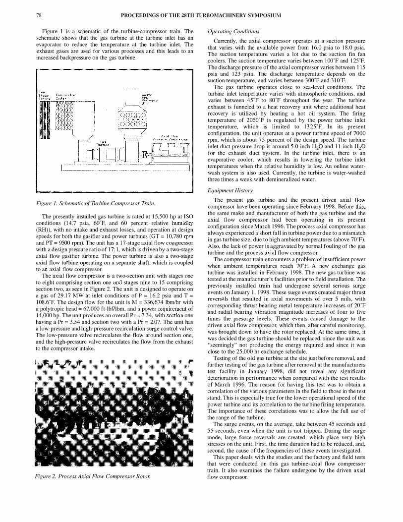
Table 2 shows the test results comparing field data taken in January with manufacturers factory test results in March 1 996 and January 1 997. The results show that the two factory tests indicated no deterioration. In fact, some of the data show an improvement. This however is within the range of instrumentation error.
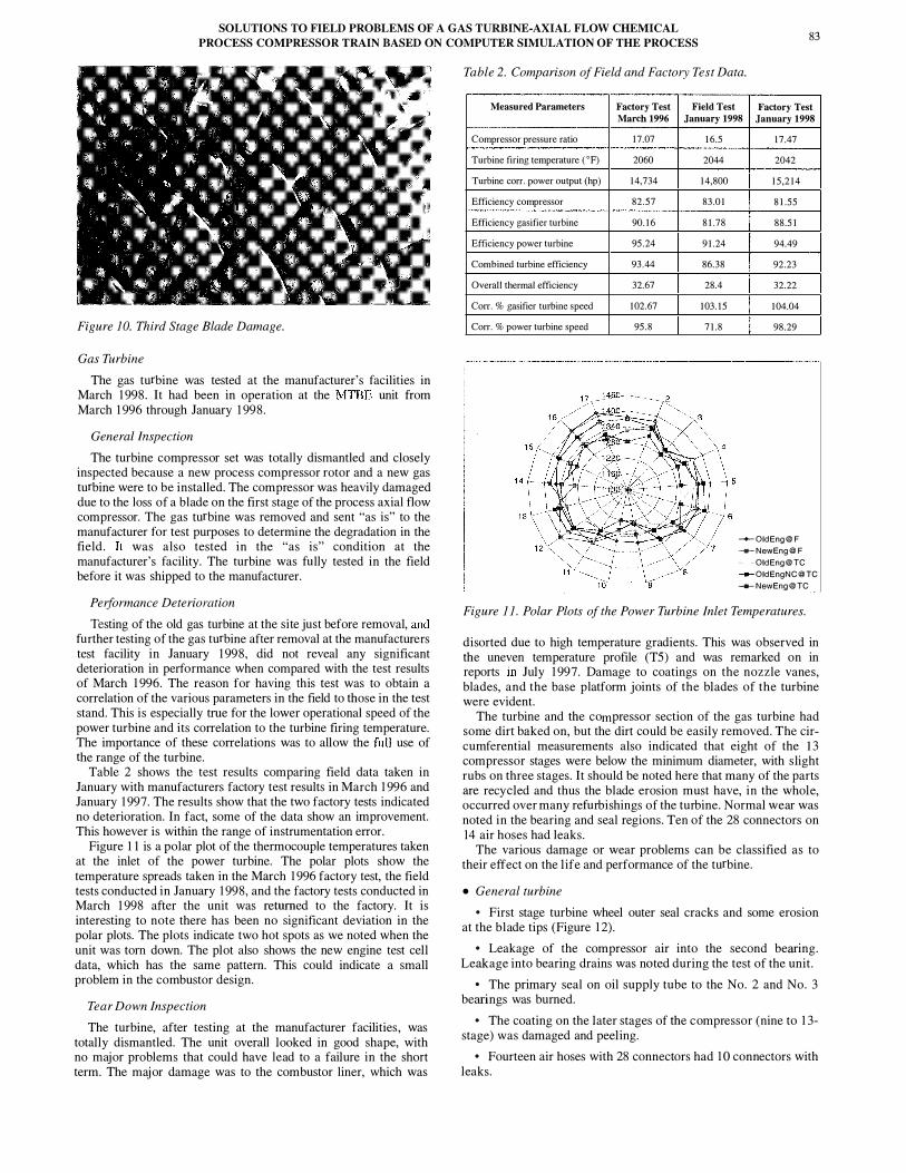
Figure 1 1 is a polar plot of the thermocouple temperatures taken at the inlet of the power turbine. The polar plots show the temperature spreads taken in the March 1 996 factory test, the field tests conducted in January 1 998, and the factory tests conducted in March 1 998 after the unit was returned to the factory. It is interesting to note there has been no significant deviation in the polar plots. The plots indicate two hot spots as we noted when the unit was tom down. The plot also shows the new engine test cell data, which has the same pattern. This could indicate a small problem in the combustor design.
Tear Down Inspection
The turbine, after testing at the manufacturer facilities , was totally dismantled. The unit overall looked in good shape, with no major problems that could have lead to a failure in the short term. The maj or damage was to the combustor liner, which was
Table 2. Comparison of Field and Factory Test Data.
Measured Parameters Factory Test March 1996
Compressor pressure ratio 17.07 Turbine firing temperature ('F) 2060 Turbine corr. power output (hp) 14,734 Efficiency compressor 82.57 Efficiency gasifier turbine 90.16 Efficiency power turbine 95.24 Combined turbine efficiency 93.44 Overall thermal efficiency 32.67 Corr. % gasifier turbine speed 102.67 Corr. % power turbine speed 95.8
Field Test Factory Test January 1998 January 1998
16.5 2044
14,800 83.01 81.78 91.24 86.38 28.4
103.15 71.8
17.47 2042
15,214 81.55 88.51 94.49 92.23 32.22
104.04 98.29
-+-OidEng@F ..,._NewEng@F ... ,. ... QJdEng@TC ---OldEngNC@ TC ---NewEng@TC
Figure 11. Polar Plots of the Power Turbine Inlet Temperatures.
disorted due to high temperature gradients. This was observed in the uneven temperature profile (TS) and was remarked on in reports in July 1 997. Damage to coatings on the nozzle vanes, blades, and the base platform joints of the blades of the turbine were evident.
The turbine and the compressor section of the gas turbine had some dirt baked on, but the dirt could be easily removed. The circumferential measurements also indicated that eight of the l3 compressor stages were below the minimum diameter, with slight rubs on three stages. It should be noted here that many of the parts are recycled and thus the blade erosion must have, in the whole, occurred over many refurbishings of the turbine. Normal wear was noted in the bearing and seal regions. Ten of the 28 connectors on 14 air hoses had leaks.
The various damage or wear problems can be classified as to their effect on the life and performance of the turbine.
• General turbine
• First stage turbine wheel outer seal cracks and some erosion at the blade tips (Figure 1 2).
• Leakage of the compressor air into the second bearing. Leakage into bearing drains was noted during the test of the unit.
• The primary seal on oil supply tube to the No. 2 and No. 3 bearings was burned.
• The coating on the later stages of the compressor (nine to 1 3-stage) was damaged and peeling.
• Fourteen air hoses with 28 connectors had 1 0 connectors with leaks.

84 PROCEEDINGS OF THE 28TH TURBOMACHINERY SYMPOSIUM
• The third stage turbine wheel had material buildup on the outer seal .
• The No. 3 bearing seemed to be using only half the journal surface. • Honeycomb seals at the outer diameter of the turbine rotor
were partially damaged. • Compressor blades had some dirt buildup. • The No. 7 fuel nozzle indicated signs of failure on the internal
tube. • Tip rubs and erosion were noted on the compressor stages
(Figure 1 3) .
Figure 12. Fatigue Cracks on First Stage Nozzle Retaining Ring.
Figure 13. Tip Rubs and Erosion Turbine Compressor Casing.
• Turbine hot section-The turbine hot section consists of the combustor and the gasifier and power turbine. There was very minor deterioration noted throughout this section for a turbine with over 20,000 hr of operation. The performance of the units hot section, which noted insignificant, if any, deterioration in the performance of the unit, bears out what was observed after the unit was inspected by taking it apart.
• Combustor section-The annular combustor had suffered two major regions of distortion due to temperature gradients experienced, caused by distortion of the combustion pattern (Figure 14) . The unit temperature polar plots (Figure 1 1 ) show the temperature profiles as heavily skewed for the turbine in the field and in the test cell . This problem had been noted and shown to the turbine manufacturer's engineers in July 1 997 . The continuation of operation with these severe gradients could result in a major failure in the combustor. The distortion was considerable and a new liner would have had to be installed within 1 000 hr of operation.
Figure 14. Combustor Liner Indicating Two Hot Spots.
Figure 1 1 also shows similar profiles in the new refurbished turbine. This profile is even sharper than in the old turbine and may require a replacement of the turbine liner earlier than anticipated.
• High temperature coatings-The high temperature coatings in the turbine, especially on the first and second stages of the turbine nozzle vanes, had experienced some damage. Various regions of the nozzle vanes and blades have experienced spalling of the coating (Figure 1 5) . This erosion of the coating can especially be noted on the leading edge of the second stage turbine nozzle vanes. No damage to the base metal was noticeable. This would indicate that this separation of the coating has occurred recently and that the environment was relatively noncorrosive. The cooling holes in the vanes and the blades were open, and no cracks were noted at the trailing edge of the blades .
Figure 15. High Temperature Coating Indicating Spalling on the Second Stage Nozzle.
The blades and the nozzle vanes of the turbine section had not experienced any high temperature excursions. No high temperature damage was noted in the hot section region of the turbine, except for the distortion of the combustor liner.
e Cracks--Cracks were noted in the retainer shroud seal areas of the compressor exhaust guide vanes. Many of these cracks were present in the unit at the last overhaul, as can be noted by the repair holes drilled to stop the crack from progressing further (Figure 1 6) . In a few instances, the cracks have reinitiated and have progressed further. These cracks could lead to increased leakage into the bearing area. In the worst case, as the crack grows, there is a potential for part of this seal breaking away and causing damage to the entire hot section region.
SOLUTIONS TO FIELD PROBLEMS OF A GAS TURBINE-AXIAL FLOW CHEMICAL PROCESS COMPRESSOR TRAIN BASED ON COMPUTER SIMULATION OF THE PROCESS 85
Figure 16. Repaired Cracks on the Retainer Ring.
Cracks also exist in the nozzle vane retaining seals. This section does not show any high temperature excursions, and thus they could have occurred due to high stresses in that region. In order to prolong the service life of these seals, the manufacturer implemented some repair techniques on minor metal cracks.
Cracks and spalling of the coating at the blade platform joints of the first stage nozzle vanes were observed. These cracks seemed to have been the result of movement during the startup and shutdown of the unit. They did not present any immediate danger to the operation of the unit.
DISCUSSION The simulation of the entire turbine compressor train has been a
major factor in ensuring that the turbine compressor train was operated consistently at or near its design condition. The simulation also enabled the unit, when it was believed that the unit was damaged, to be operated till a time when the plant could be ready to quickly tum around the unit, after a complete overhaul and replacement of the axial flow process compressor and the gas turbine, respectively.
The equations have shown that to properly simulate the operation of the train and to determine the deterioration taking place, the values must be corrected and transposed. The changes in ambient conditions cause substantial changes in the operation of a gas turbine. The effect of humidity increase is to lower the corrected speed. An increase in ambient temperature is to lower the power output and reduce the corrected speed. The rule of thumb would be that a lO"F change would change the corrected speed by one percent. I t will also reduce the power by about two percent.
The effect on the turbine firing temperature is due to many different parameters. A reduction in compressor efficiency, an increase in ambient temperature, and a reduction of gasifier efficiency would increase the firing temperature. Due to the limitation of the power available on this turbine, the firing temperature envelope is being pushed to its limits. An online calculation of the firing temperature has been essential in obtaining a safe and operable maximum power output from this turbine.
The compressor train encounters a problem of insufficient power when ambient temperatures reach 70"F. The new gas turbine, which is rated at 15 ,500 hp, was tested at the manufacturers facilities and installed in February 1 998. This train has, as has the previously installed train, undergone several surge events since February 1 998. These surge events create major thrust reversals that have resulted in axial movements of over 3 mils, with corresponding thrust bearing metal temperature increases of 20"F and radial bearing vibration magnitude increases of four to five times the presurge levels.
Over the past year since the new unit was installed, the gas turbine power has been increased by increasing the firing
temperature by increasing the power turbine temperature setting by over 20"F. This was done after data had been presented to the manufacturer's engineers showing that the firing temperature was below the 2050"F, the temperature on which the life hours of the turbine are based. This is also the basis of the contractual agreement between the user and the manufacturer.
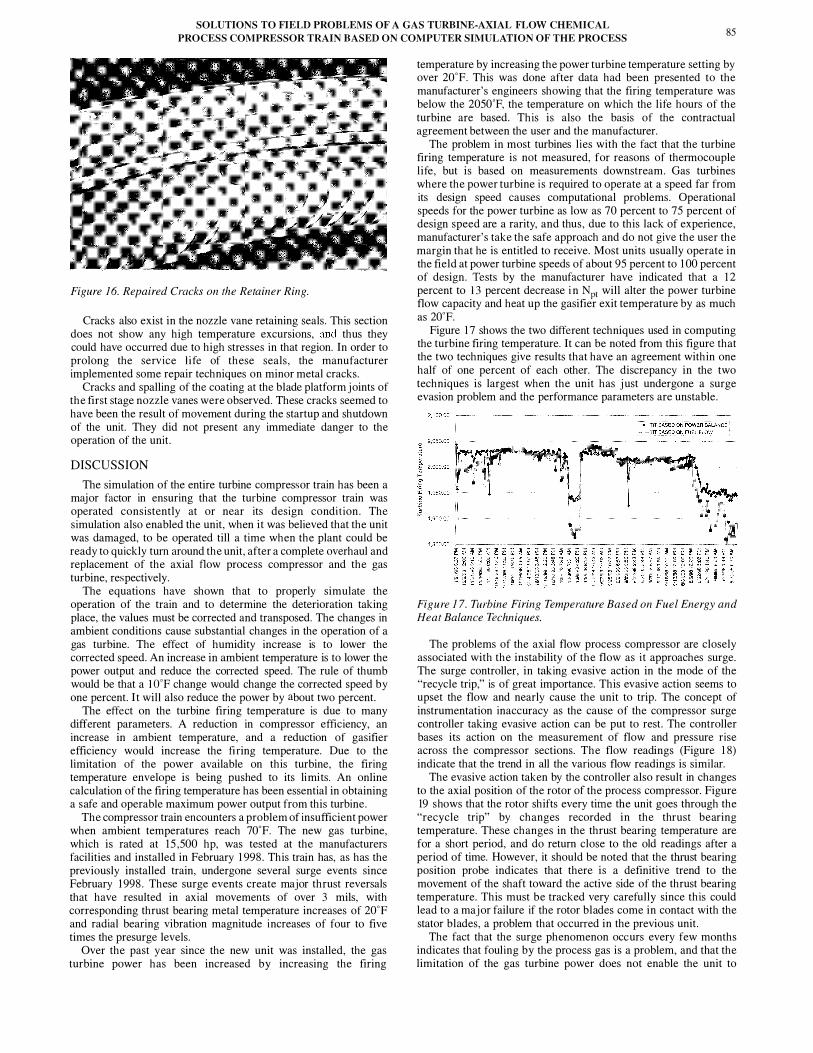
The problem in most turbines lies with the fact that the turbine firing temperature is not measured, for reasons of thermocouple life, but is based on measurements downstream. Gas turbines where the power turbine i s required to operate at a speed far from its design speed causes computational problems. Operational speeds for the power turbine as low as 70 percent to 75 percent of design speed are a rarity, and thus, due to this lack of experience, manufacturer's take the safe approach and do not give the user the margin that he is entitled to receive. Most units usually operate in the field at power turbine speeds of about 95 percent to 1 00 percent of design. Tests by the manufacturer have indicated that a 1 2 percent to 13 percent decrease i n Npt will alter the power turbine flow capacity and heat up the gasifier exit temperature by as much as 20"F.
Figure 1 7 shows the two different techniques used in computing the turbine firing temperature. It can be noted from this figure that the two techniques give results that have an agreement within one half of one percent of each other. The discrepancy in the two techniques is largest when the unit has just undergone a surge evasion problem and the performance parameters are unstable.
Figure 17. Turbine Firing Temperature Based on Fuel Energy and Heat Balance Techniques.
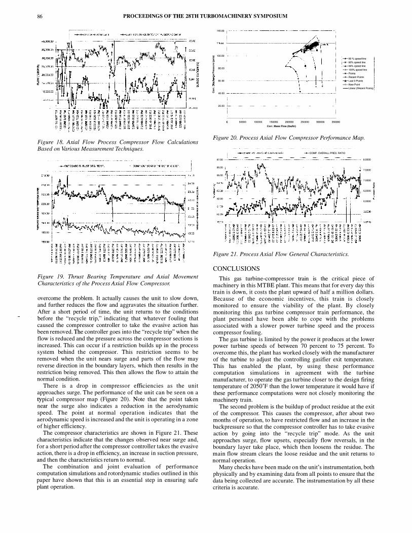
The problems of the axial flow process compressor are closely associated with the instability of the flow as it approaches surge. The surge controller, in taking evasive action in the mode of the "recycle trip," is of great importance. This evasive action seems to upset the flow and nearly cause the unit to trip. The concept of instrumentation inaccuracy as the cause of the compressor surge controller taking evasive action can be put to rest. The controller bases its action on the measurement of flow and pressure rise across the compressor sections. The flow readings (Figure 1 8) indicate that the trend in all the various flow readings is similar.
The evasive action taken by the controller also result in changes to the axial position of the rotor of the process compressor. Figure 19 shows that the rotor shifts every tiine the unit goes through the "recycle trip" by changes recorded in the thrust bearing temperature. These changes in the thrust bearing temperature are for a short period, and do return close to the old readings after a period of time. However, it should be noted that the thrust bearing position probe indicates that there is a definitive trend to the movement of the shaft toward the active side of the thrust bearing temperature. This must be tracked very carefully since this could lead to a major failure if the rotor blades come in contact with the stator blades, a problem that occurred in the previous unit.
The fact that the surge phenomenon occurs every few months indicates that fouling by the process gas is a problem, and that the limitation of the gas turbine power does not enable the unit to
86 PROCEEDINGS OF THE 28TH TURBOMACHINERY SYMPOSIUM
Figure 18. Axial Flow Process Compressor Flow Calculations Based on Various Measurement Techniques.
185.00
Figure 19. Thrust Bearing Temperature and Axial Movement Characteristics of the Process Axial Flow Compressor.
overcome the problem. It actually causes the unit to slow down, and further reduces the flow and aggravates the situation further. After a short period of time, the unit returns to the conditions before the "recycle trip," indicating that whatever fouling that caused the compressor controller to take the evasive action has been removed. The controller goes into the "recycle trip" when the flow is reduced and the pressure across the compressor sections is increased. This can occur if a restriction builds up in the process system behind the compressor. This restriction seems to be removed when the unit nears surge and parts of the flow may reverse direction in the boundary layers, which then results in the restriction being removed. This then allows the flow to attain the normal condition.
There is a drop in compressor efficiencies as the unit approaches surge. The performance of the unit can be seen on a typical compressor map (Figure 20). Note that the point taken near the surge also indicates a reduction in the aerodynamic speed. The point at normal operation indicates that the aerodynamic speed is increased and the unit i s operating in a zone of higher efficiency.
The compressor characteristics are shown in Figure 2 1 . These characteristics indicate that the changes observed near surge and, for a short period after the compressor controller takes the evasive action, there is a drop in efficiency, an increase in suction pressure, and then the characteristics return to normal.
The combination and j oint evaluation of performance computation simulations and rotordynamic studies outlined in this paper have shown that this is an essential step in ensuring safe plant operation.
14<>.00 ,-------------------,
I 100.00 --+-85 % speed line -llt--90% speed Rne -A-95%speeclllne -8!-1 00% speed nne --Points ....,._..Recent Polnts -A-Last3Polnts -lP- New Point
I �.00 +------�--t---+-+----1
I 00 00 t-----------+--.�t-t-t--1
� 40.00 +------------�------1 I Unear(RectJntPolnts)
20.00
50000 100000 150000 200000 250000 300000 350000 Corr. Mull Flow (lbtlhr)
Figure 20. Process Axial Flow Compressor Performance Map.
_...COMP. OVERALL PRES. RATIO
87.00 8.0000
86.00 7.5000
85.00
7.0000
r·'t i
83.00 60000 I 11-82.00 6.0000
Figure 21. Process Axial Flow General Characteristics.
CONCLUSIONS This gas turbine-compres sor train is the critical piece of
machinery in this MTBE plant. This means that for every day this train is down, it costs the plant upward of half a million dollars. Because of the economic incentives , this train i s closely monitored to ensure the viability of the plant. By closely monitoring this gas turbine compressor train performance, the plant personnel have been able to cope with the problems associated with a slower power turbine speed and the process compressor fouling.
The gas turbine is limited by the power it produces at the lower power turbine speeds of between 70 percent to 75 percent. To overcome this, the plant has worked closely with the manufacturer of the turbine to adjust. the controlling gasifier exit temperature. This has enabled the plant, by using these performance computation simulations in agreement with the turbine manufacturer, to operate the gas turbine closer to the design firing temperature of 20so·F than the lower temperature it would have if these performance computations were not closely monitoring the machinery train.
The second problem is the buildup of product residue at the exit of the compressor. This causes the compressor, after about two months of operation, to have restricted flow and an increase in the backpressure so that the compressor controller has to take evasive action by going into the "recycle trip" mode. As the unit approaches surge, flow upsets, especially flow reversals, in the boundary layer take place, which then loosens the residue. The main flow stream clears the loose residue and the unit returns to normal operation.
Many checks have been made on the unit' s instrumentation, both physically and by examining data from all points to ensure that the data being collected are accurate. The instrumentation by all these criteria is accurate.

SOLUTIONS TO FIELD PROBLEMS OF A GAS TURBINE-AXIAL FLOW CHEMICAL
PROCESS COMPRESSOR TRAIN BASED ON COMPUTER SIMULATION OF THE PROCESS 87
To sum up, the performance computation simulation is a very critical part of the safe and efficient operation of the plant. The performance simulation ensures that: • The gas turbine is operated at a safe, but maximum, temperature to ensure that the unit is operated at its maximum possible power. • The gas turbine operation is not minimized due to a dirty compressor or a wrong positioning of the inlet guide vane (IGV). • The gas turbine combustion calculated temperature is monitored closely along with any skewing of the power turbine inlet temperature. By monitoring both parameters, it is relatively easy to detect and avoid any hot spots in the combustion liner. • The computation of turbine component efficiencies gives early indication of any fouling. • The performance computation of the process axial compressor can be used to determine the proper level of maintenance required. The performance computations have been used to evaluate the health of the process compressor and have been used to predict when offline washing will be required to restore its performance. These same computations have been used to evaluate whether or not a major overhaul is required. • The process axial flow compressor is operated as close as possible to the surge line, ensuring operation at its maximum efficiency point, which is critical due to the limitation of gas turbine power.
APPENDIX A AXIAL FLOW PROCESS COMPRESSOR CALCULATIONS Axial Flow Process Compressor
Performance Calculation Assumptions
The computations for the axial flow compressor were based on the properties of the gas computed, based on the specific gravity of the gas and its influence on the molecular weight (MW) of the gas. The gas properties were computed as a function of the temperature and pressure, and compensated for these functions throughout the calculations . The gas at each point was then considered to be thermally and calorically perfect. The gas properties for the process were not considered to be calorically perfect, but were based on an average value for that process. The fundamental equations, which govern the properties of the compressor, were the equation of state, conservation of mass, momentum, and energy equations. • Equation of state
� = Z _g_ T p MW
where: p Total pressure (lbf /sqft) T p z R
= Total temperature CR = oF+459.67) = Density of the gas (lbm/cuft)
Compressibility factor
MW = Universal gas constant = 1 545 .32 ft-lb(pmole oR Molecular weight of the gas (lbm/pmole)
• Conservation of mass
where: m = Mass flow (lbdsec) A = Area (sqft) V = Gas velocity (ft/sec) • Momentum equation
m = pAV
(A- 1 )
(A-2)
For a calorically and thermally perfect gas, and one in which the radial and axial velocities do not contribute to the forces generated on the rotor (Euler turbine equation) :
where: Hdad u Ve
Adiabatic head or energy per unit mass (fclbiJbm) Blade speed (ft/sec)
(A-3)
Tangential component of the absolute velocity of the gas (ft/sec) Newtonian proportionality constant (32. 1 74 ft-lbmnbr sec2)
• Energy equation
For a calorically and thermally perfect gas, and assuming no substantial change in the kinetic energy in the system:
y. ZR T1 [p � (L..!.) HD ct = MW ( _1 'Y - 1 } (A-4) a y- 1 PI
c where 'Y = :::£ for an adiabatic process;
Cv where CP and Cv are the specific heats of the gas at constant pressure and volume, respectively, and can be written as:
where:
c = _yg_ p y- 1 and R c = -v y- 1
(A-5)
(A-6)
and PI> P2, are the gas total pressures at the inlet and exit, and T1 is the gas absolute total temperature in OR at the inlet.
The relationship between total and static conditions for pressure and temperature are as follows :
(A-7)
where: T8 = Static temperature V = Gas stream velocity and:
(A-8)
where: P8 = S tatic pressure and the acoustic velocity of a gas is given by the following relationship:
(A-9)
For an adiabatic process (s = entropy = constant), the acoustic speed can be written as follows:
where:
a - � ygcRT s -MW
Ts = Static temperature ( "R)
(A- 1 0)
Equation (A-4) defines the adiabatic head, but since the actual process is not adiabatic but a polytropic process, the value of r is replaced by the following relationship for the polytropic exponent (n):
1 n [:� (A- l l )
88 PROCEEDINGS OF THE 28TH TURBOMACIDNERY SYMPOSIUM
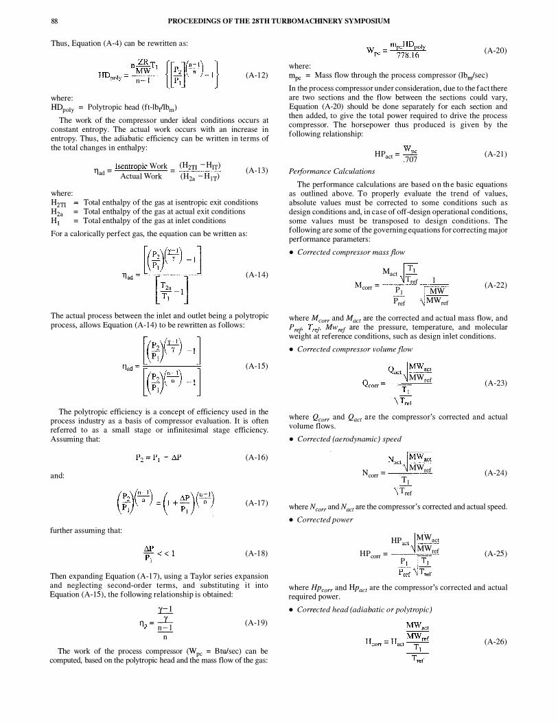
Thus , Equation (A-4) can be rewritten as :
(A- 1 2)
where: HDpoly = Polytropic head (ft-lbf"lbm)
The work of the compressor under ideal conditions occurs at constant entropy. The actual work occurs with an increase in entropy. Thus, the adiabatic efficiency can be written in terms of the total changes in enthalpy:
where: Hzn Hza Ht
11 _ Isentropic Work _ (Hzn -Hrr) ad - Actual Work - (H2a - Hn)
(A- 1 3)
Total enthalpy of the gas at isentropic exit conditions = Total enthalpy of the gas at actual exit conditions = Total enthalpy of the gas at inlet conditions
For a calorically perfect gas, the equation can be written as :
(A- 1 4)
The actual process between the inlet and outlet being a polytropic process, allows Equation (A- 1 4) to be rewritten as follows :
(A- 1 5)
The polytropic efficiency is a concept of efficiency used in the process industry as a basis of compressor evaluation. It is often referred to as a small stage or infinitesimal stage efficiency. Assuming that:
(A- 1 6)
and:
(A- 17 )
further assuming that:
(A- 1 8)
Then expanding Equation (A- 1 7) , using a Taylor series expansion and neglecting second-order terms, and substituting i t into Equation (A- 15 ) , the following relationship is obtained:
ti Tl - _:]_ ' tp - n - 1
n (A- 1 9)
The work of the process compressor (Wpc = Btu/sec) can be computed, based on the polytropic head and the mass flow of the gas :
(A-20)
where: IDpc = Mass flow through the process compressor (Ibn/sec) In the process compressor under consideration, due to the fact there are two sections and the flow between the sections could vary, Equation (A-20) should be done separately for each section and then added, to give the total power required to drive the process compressor. The horsepower thus produced is given by the following relationship:
HP - wpc act - .707 Performance Calculations
(A-2 1 )
The performance calculations are based o n th e basic equations as outlined above. To properly evaluate the trend of values, absolute values must be corrected to some conditions such as design conditions and, in case of off-design operational conditions, some values must be transposed to design conditions. The following are some of the governing equations for correcting major performance parameters : • Corrected compressor mass flow
Mact M = ref 1
corr p1 � MW Pref MWref
(A-22)
where Mcorr and Mact are the corrected and actual mass flow, and P ref T ref Mw ref are the pressure, temperature, and molecular we1ght at reference conditions, such as design inlet conditions. • Corrected compressor volume flow
Qact �MWact MWref (A-23)
where Qcorr and Qact are the compressor's corrected and actual volume flows. • Corrected (aerodynamic) speed
Nact�MWact N = MWref corr � Tl
Tref
(A-24)
where Ncorr and Nact are the compressor's corrected and actual speed. • Corrected power
HP act� MW act HP = MWref corr Pl ['f;
Pref � �
(A-25 )
where HPcorr and HPact are the compressor's corrected and actual required power. • Corrected head (adiabatic or polytropic)
(A-26)

SOLUTIONS TO FIELD PROBLEMS OF A GAS TURBINE-AXIAL FLOW CHEMICAL
PROCESS COMPRESSOR TRAIN BASED ON COMPUTER SIMULATION OF THE PROCESS 89
where Hcorr and Hact are the compressor's corrected and actual head produced. • Corrected pressure
Pact Pcorr = �
Pref
(A-27)
where P corr and Pact are the compressor's corrected and actual total pressure. • Corrected temperature
T = Tact MW eorr � MW _1 ref
Tref
(A-28 )
where Tcorr and Tact are the compressor's corrected and actual total temperature.
APPENDIX B GAS TURBINE CALCULATIONS Gas Turbine Peiformance Calculation Assumptions
The gas turbine is fully instrumented in the field to ensure that the data evaluated would be accurate and that the turbine would be operated at its maximum power. The turbine operating in this application is "designed" to operate at 75 percent of the power turbine speed. The manufacturer uses the temperature at the exit of the gasifier turbine to determine the firing temperature and hence the power delivered by the power turbine. The operation of the power turbine at 75 percent of the design speed affects the exit temperature. Therefore, modifications had to be made to normal techniques used by the manufacturer whose experience is mainly with the turbine operating at 1 00 percent of the design power turbine speed.
The overall compressor work is calculated using the following relationship:
The work per stage is calculated assuming the energy per stage is equal. This has been found to be a better assumption than assuming the pressure ratio per stage to be equal. It is necessary to know this if there is interstage bleed of the air for cooling or other reasons.
(B-2)
where: Nstg = Number of compressor stages The compressor adiabatic efficiency can be computed using Equation (A- 1 5) . In a gas turbine, due to the high compression ratio, the adiabatic efficiency is applicable.
The calculation of the turbine firing temperature (T1it) is based first on the fuel injected into the turbine and the fuel' s lower heating value (LHV). The lower heating value of the gas is one in which the H20 in the product has not condensed. The lower heating value is equal to the higher heating value, minus the latent heat of the condensed water vapor.
(B-3)
where: Htit Enthalpy of the combustion gas at the firing temperature rna = Mass of air
mb = B leed air mf = Mass of fuel Tlb Combustor efficiency (usually between 95 percent and 98
percent) The turbine firing temperature should be computed by knowing
the gas characteristics of the combustion gas. If these characteristics are known, then one can use the equations given in ASME PTC 4.4 ( 1 992). Usually, the gas constituents are not continuously monitored and are rarely known at any given point, so it i s not a bad assumption to use the 400 percent theoretical air tables in the Keenan and Kaye ( 1983) gas tables. The following equations for specific heat at constant pressure and the ratio of specific heats have been obtained, based on the air tables and based on a fuel with a mole weight of the combustion gas to be 28.9553 lbm/pmole.
cp = - 2.76E(- 10)T2 + 1 . 1 528E(-5)T + .237 (B-4)
and: c
'Y = ---"----
(c _ 77� 16\ P MW J
(B-5)
The turbine firing temperature based on the heat balance can also be computed and must be within about 2•F to 5•p of each other. The heat balance relationships as they apply to the gas turbine:
where:
We Wpe :;;-- + , + (ma + mr)Hexit
H _ · •me · •mt tit - (rna + mf- mb)
We = Work of the gas turbine compressor (Btu/sec) W pc = Work of the process compressor Time = Mechanical loss in the turbine compressor drive
(B-6)
Tlmt = Mechanical loss in the turbine process compressor drive Hexit = Enthalpy at turbine exit
Split shaft gas turbines usually have temperature measurements at the gasifier turbine exit and also at the power turbine exit. From experience and also based on theoretical relationships , the temperature ratio of the temperature at the gasifier inlet (Tti1) and the temperature of the power turbine inlet temperature (Tpit) for a given geometry remains constant, even though the load and ambient conditions change. It is because of this that most manufacturers limit the engine based on the power turbine inlet temperature.
(B-7)
This also enables Equation (B-6) for the case of a split shaft turbine to be rewritten:
(B-8)
where an assumption of 40 percent of the bleed flow was assumed to have entered the turbine through the cooling mechanisms of the first few stages of the turbine. This assumption is specific to this turbine only.
To ensure that the heat balance is accurate, the following relationship indicates the accuracy of the computations. This heat balance ratio can be written as follows :
� 11 + (rna + mr)Hexit- maHiniet HBratio = ....:.::m:::.t ____ -=-==----
ffit * LHV (B-9)

90 PROCEEDINGS OF THE 28TH TURBOMACHINERY SYMPOSIUM
This ratio should be between .96 and 1 . 04. The work produced by the gasifier turbine (W81) is equal to the
gas turbine compressor work (We):
(B- 1 0)
The gasifier turbine efficiency (TJ81) :
11 t = Htit- Hpita 1 00 g Htit- Hpiti (B- 1 1 )
where Hpita is the enthalpy of the gas based on the actual temperature at the exit of the gasifier turbine, and Hpiti is the enthalpy of the gas based on the ideal temperature at the exit of the gasifier turbine. To obtain this ideal enthalpy, the pressure ratio across the gasifier turbine must be known.
The pressure ratio (P8n) across the turbine depends on the pressure drop (Mcb) through the combustor. This varies in various combustor designs where a pressure drop is between one percent and three percent of the compressor discharge pressure.
p _ Pdc( l - aPcb) grt - p dgt (B- 1 2)
where P dgt is the pressure at the gasifier turbine exit. Thus , the ideal enthalpy at the gasifier turbine exit is given by:
Htit H . . = (B- 13) pltl c
. (:t:..!.) � pgrt y CPpit
where y is based on an average temperature across the gasifier turbine, based on Equation (B-5) . The power turbine efficiency can be computed using Equations (B- 1 1 ) and (B- 1 3) .
The overall thermal efficiency of the gas turbine in a simple cycle (varies between 25 percent and 50 percent, depending on the turbine) is computed to determine deterioration of the turbine:
�
'llmt 11 th = mrLHV 1 00
The heat rate can now easily be computed:
where:
2544.4 HR = --
11 th 100
HR = Heat rate (Btulhp-hr)
Gas Turbine Performance Calculations
(B- 1 4)
(B- 1 5)
The performance of the gas turbine is based on the basic equations in the prior section. To relate these relationships to the turbine in concern, and to calculate the deterioration of different sections of the gas turbine, the values obtained must be corrected to design conditions and, in some cases, values would have to be transposed from off-design conditions to the design conditions . The corrected values define the engine corrected performanc,e values . Geometric similarity such as blade characteristics, clearances, nozzle areas, and guide vane settings do not change when geometric similarity is constant. Dynamic similarity, which relates to such parameters as gas velocities and turbine speeds, when maintained together with the geometric similarity, ensures that these corrected parameters will maintain the engine performance at all operating conditions .
• Corrected mass flow
(B- 1 6)
Pstd where macorr and rna are the corrected and actual mass flow of the air entering the gas turbine inlet. These corrections are from the ambient conditions to, usually, the ISO conditions .
The corrected speed for both the gasifier and power turbine defines the corrected engine performance. • Corrected speed
Ncorr Na �
�� • Corrected temperature
• Corrected fuel flow
• Corrected power
TA T - -corr - Tinlet Tstd
HP Tinlet
act T HPcorr = std
Pinlet Pstd
(B- 1 7)
(B- 1 8)
(B- 1 9)
(B-20)
The above relationship has to be further modified to take into account the pressure drop in the inlet ducting, the increase in backpressure due to exhaust ducting, the off-design operation due to decrease in turbine firing temperature, and the decrease in speed of the power turbine. These modifications are used to calculate the transposed power (HPp1) by transposing from the off-design output power at operating conditions of the turbine to the design conditions. • Transpose power output
where .1P c is the pressure drop at the inlet due to the filters and evaporator in the inlet ducting, P wi is the power loss per inch of H20 drop, Me is the backpressure at the discharge due to the exhaust ducting, and P we is the power loss per inch of H20 drop. The power factor (m) to which the speed ratio i s raised will vary with turbines. In the case of this turbine, the value was m = 0.4.
REFERENCES ASME PTC 4.4, 1 992, "Gas Turbine Heat Recovery Steam
Generators," American Society of Mechanical Engineers, New York, New York.
Keenan, J. H. and Kaye, J . , 1983 , Gas Tables, New York, New York, John Wiley & Sons.

SOLUTIONS TO FIELD PROBLEMS OF A GAS TURBINE-AXIAL FLOW CHEMICAL
PROCESS COMPRESSOR TRAIN BASED ON COMPUTER SIMULATION OF THE PROCESS 9 1
BffiLIOGRAPHY ASME PTC 10 , 1 997, "Performance Test Code on Compressors
and Exhausters," American Society of Mechanical Engineers, New York, New York.
ASME PTC 22, 1 997, "Performance Test Code on Gas Turbines," American Society of Mechanical Engineers, New York, New York.
B arnes, G. , Boyce, M . P. , Wooldridge, B . , and Meher-Homji , C. B . , 1 989, "On-Line Condition Monitoring o f Two Westinghouse CE 352 Gas Turbine Compressor Sets," Proceedings of the Eighth NRCC Symposium on Industrial Application of Gas Turbines, Ottawa, Canada, pp. 85-98 .
Boyce, M. P. , 1 985 , "Higher Availability and Efficiency Using OnLine Real Time Diagnostic and Prognostic System on Gas Turbine Compressor Trains," Presented at the ASME Beijing International Gas Turbine Symposium and Exposition, Beij ing, China.
Boyce, M. P. , 1 988 , "Advanced Maintenance Management System Design for the LM2500 Gas Turbine," Presented at the SAE Conference and Exposition on Future Transportation Technology, San Francisco, California, SAE Paper No. 88 1 1 7 1 .
Boyce, M . P. , 1 988 , "Advanced Condition Monitoring Protection and Control of Turbomachinery," Presented at the BHRA Conference, Milton Keynes, United Kingdom, Paper C-4.
Boyce, M. P., 1 989, "Performance Monitoring of Cogeneration Facilities ," Presented at the First International POWER Technology Exposition and Conference, Chicago, Illinois .
Boyce, M. P. , June 1 993 , "Turbomachinery Condition Monitoring Systems for the Hydrocarbon Processing Industry," Hydrocarbon Technology International Magazine.
Boyce, M. P. , 1 993 , "Principles of Operation and Performance Estimation of Centrifugal Compressors," Proceedings of the Twenty-Second Turbomachinery Symposium, Turbomachinery Laboratory, Texas A&M University, College Station, Texas , pp. 1 6 1 - 178 .
Boyce, M. P. , 1 994, "Control and Monitoring an Integrated Approach," Presented at Middle East Electricity, pp. 1 7-20.
Boyce M. P. , 1 995 , Gas Turbine Engineering Handbook, Third Printing, Houston, Texas : Gulf Publishing Company.
Boyce, M. P. , 1 996, "Improving Performance with Condition Monitoring," Power Plant Technology Economics and Maintenance, pp. 52-55 .
Boyce, M. P. , 1 998 , "Total Performance Condition Monitoring of Major Petrochemical Facilities," Presented at the Materials Selection and Application in the Chemical Process Industry, Sponsored by The Institute of Materials and The Institute of Chemical Engineers, London, England.
Boyce, M. P. and Cox, W. M. , 1 997, "Condition Monitoring Management-Strategy," Presented at The Intelligent Software Systems in Inspection and Life Management of Power and Process Plants, Paris, France.
Boyce, M. P. and Echegaray, L. E . , 1 989 , "Aerothermal Analysis Improves Efficiency and Availability of Turbomachinery," Plant Services Handbook of Computerized Maintenance Management and Predictive Maintenance, pp. 1 02- 1 04 .
Boyce, M. P. and Herrera, G . , 1 993, "Health Evaluation of Turbine Engines Undergoing Automated FAA Type Cyclic Testing," Presented at the SAE International Aerotech '93 , Costa Mesa, California, SAE Paper No. 932633 .
Boyce, M . P. and Venema, J . , 1 997, "Condition Monitoring and Control Center," Presented at PowerGen Europe, Madrid, Spain.
Boyce, M. P., Bhargava, R. K. , and Chinoy, R . , 1 989, "On-Line Condition Monitoring of Turbomachinery," Proceedings of the First International Machinery Monitoring and Diagnostic Conference, Las Vegas, Nevada, pp. 4 1 9-427 .
B oyce, M . P. , Gabriles, G. A . , Meher-Homj i , C . B . , Lakshminarasimha, A . N. , and Meher-Homji , F. J . , 1 993 , "Case Studies in Turbomachinery Operation and Maintenance Using Condition Monitoring," Proceedings of the TwentySecond Turbomachinery Symposium, Turbomachinery Laboratory, Texas A&M University, College Station, Texas, pp. 1 0 1 - 1 12 .
Boyce, M. P. , Gabriles, G. A . , and Meher-Homji , C . B . , 1 993 , "Enhancing System Availability and Performance in Combined Cycle Power Plants by the Use of Condition Monitoring," Presented at the European Conference and Exhibition Cogeneration of Heat and Power, Athens , Greece .
Boyce, M. P. , Lakshminarasimha, A. N . , and Meher-Homji , C . B . , 1 992, "Design and Implementation o f a n Advanced MultiMachine Gas Turbine Train Condition Monitoring and Control System," Presented at the Third Congress of Turbomachinery, Queretaro, Mexico.
Boyce, M. P. , Meher-Homji, C . B . , and Lakshminarasimha, A . N . , 1 993 , "Evolution o f a Unified Turbomachinery Condition Monitoring System and its Application to Gas and Steam Turbine Utility Plants," Proceedings of the Third EPRl Steam Turbine/Generator Workshop, Albany, New York.
Boyce, M. P. , Meher-Homji, C. B . , and Mani, G . , 1 989, "A Diagnostic Methodology for Condition Monitoring of High Speed Turbomachinery," Presented at the Society of Tribologists and Lubrication Engineers Conference, Atlanta, Georgia, Publication No. STLE SP-27 .
Boyce, M. P. , Meher-Homji , C. B . , and Wooldridge, B . , 1 989, "Condition Monitoring of Aeroderivative Gas Turbines," Presented at the Gas Turbine and Aeroengine Congress and Exposition, Toronto, Canada, ASME Paper No. 89-GT-36.
GPA, Revised 1 994, "Table of Physical Constants of Paraffin Hydrocarbons and Other Components of Natural Gas," Gas Processors Association.
ISO, 1 983 , "Natural Gas-Calculation of Calorific Value, Density and Relative Density," International Organization for Standardization, ISO 6976- 1 983(E).
Lakshminarasirnha, A . N., Boyce, M. P. , and Meher-Homji , C . B . , 1 993 , "Modeling and Analysis of Gas Turbine Performance Deterioration," Presented at the Thirty-Seventh ASME International Gas Turbine and Aeroengine Congress and Exposition, Cologne, Germany, ASME Paper No. 93-GT-395 .
Meher-Homji , C. B . , B oyce, M. P. , Lakshminarasirnha, A. N . , Whitten, J . A . , and Meher-Homji , F. J . , 1 993 , "Condition Monitoring and Diagnostic Approaches for Advanced Gas Turbines," Proceedings ASME Cogen Turbo Power 1 993 , Seventh Congress and Exposition on Gas Turbines in Cogeneration and Utility, Sponsored by ASME in participation with BEAMA, IGTI-8 , Bournemouth, United Kingdom, pp. 347-355 .
Unsal, R. and Boyce, M . P. , 1 988 , "Experience with an Online Condition Monitoring System," Proceedings of the Seventeenth Turbomachinery Symposium, Turbomachinery Laboratory, Texas A&M University, College Station, Texas, pp. 57-66.

92 PROCEEDINGS OF THE 28TH TURBO MACHINERY SYMPOSIUM