som-2355 som-144 moduleadvdownload.advantech.com/productfile/downloadfile… · ·...
TRANSCRIPT

SOM-2355 SOM-144 ModuleAMD Geode LX800 CPU Module with CPU, VGA/LVD & LAN
User Manual

Copyright Notice
This document is copyrighted, 2007, by Advantech Co., Ltd. All rights are reserved. The original manufacturer reserves the right to make improvements to the products described in this manual at any time with-out notice. No part of this manual may be reproduced, copied, translated or transmitted in any form or by any means without the prior written per-mission of the original manufacturer. Information provided in this manual is intended to be accurate and reliable. However, the original manufac-turer assumes no responsibility for its use, nor for any infringements upon the rights of third parties which may result from its use.
SOM-2355 User Manual ii

Acknowledgements
SOM and DTOS are trademarks of Advantech Co., Ltd. AMD is a trademark of Advanced Micro Devices, Inc. Award is a trademark of Award Software International, Inc.Cyrix is a trademark of Cyrix Corporation. IBM, PC/AT, PS/2 and VGA are trademarks of International Business Machines Corporation.Intel and Pentium are trademarks of Intel Corporation.Microsoft Windows® is a registered trademark of Microsoft Corp. RTL is a trademark of Realtek Semiconductor Co., Ltd.C&T is a trademark of Chips and Technologies, Inc.UMC is a trademark of United Microelectronics Corporation.Winbond is a trademark of Winbond Electronics Corp.STPC is a trademark of SGS Thomson Corp.
For more information on this and other Advantech products, please visit our website at: http://www.advantech.comFor technical support and service, please visit our support website at: http://www.advantech.com/supportThis manual is for the SOM-2355
Part No. 2006235500 1st EditionPrinted in Taiwan Mar. 2007
iii

Packing List
Before you begin installing your card, please make sure that the following materials have been shipped:� SOM-2355 System On Module CPU module� CD-ROM or Disks for utility, drivers, and manual (in PDF format)
If any of these items are missing or damaged, contact your distributor or sales representative immediately.
Additional Information and Assistance
1. Visit the Advantech web site at www.advantech.com where you can find the latest information about the product.
2. Contact your distributor, sales representative, or Advantech's cus-tomer service center for technical support if you need additional assistance.
Please have the following information ready before you call:� Product name and serial number� Description of your peripheral attachments� Description of your software (operating system, version, application
software, etc.)� A complete description of the problem� The exact wording of any error messages
SOM-2355 User Manual iv

Declaration of Certification
CEThis product has passed the CE test for environmental specifications. Test conditions for passing included the equipment being operated within an industrial enclosure. In order to protect the product from being damaged by ESD (Electrostatic Discharge) and EMI leakage, we strongly recom-mend the use of CE-compliant industrial enclosure products.
FCC Class ANote: This equipment has been tested and found to comply with the limits for a Class A digital device, pursuant to part 15 of the FCC Rules. These limits are designed to provide reasonable protection against harmful interference when the equipment is operated in a commercial environ-ment. This equipment generates uses and can radiate radio frequency energy and, if not installed and used in accordance with the instructions manual, may cause harmful interference to radio communications. Oper-ation of this equipment in a residential area is likely to cause harmful interference in which case the user will be required to correct the interfer-ence at his own expense.
Caution! There is a danger of a new battery exploding if it is incorrectly installed. Do not attempt to recharge, force open, or heat the battery. Replace the battery only with the same or equivalent type recommended by the manufacturer. Discard used batteries accord-ing to the manufacturer�s instructions.
v

SOM-2355 User Manual vi

ContentsChapter 1 General Information ........................................2
1.1 Introduction ....................................................................... 21.2 Specifications .................................................................... 2
1.2.1 Standard System On Module functions .......................... 21.2.2 VGA/flat panel Interface ................................................ 31.2.3 Audio function ................................................................ 31.2.4 Ethernet........................................................................... 31.2.5 Mechanical and environmental....................................... 3
Chapter 2 Mechanical Information ..................................62.1 Board Connector ............................................................... 6
Figure 2.1 SOM-144 Locating Connectors................ 62.2 Board Mechanical Drawing .............................................. 7
2.2.1 Front Side........................................................................ 7Figure 2.2 SOM-2355 Front Side Drawing ............... 7
2.2.2 Rear Side......................................................................... 8Figure 2.3 SOM-2355 Rear Side Drawing................. 8
Chapter 3 BIOS Setup Information................................103.1 Introduction ..................................................................... 103.2 Safety Precautions .......................................................... 103.3 BIOS Update ................................................................... 103.4 Basic BIOS Setup............................................................ 12
3.4.1 Enter the BIOS setup screen ......................................... 123.4.2 Main Setup Item............................................................ 13
Chapter 4 Driver Installation..........................................164.1 Driver Introduction.......................................................... 164.2 Driver Installation ........................................................... 17
4.2.1 Step 1- Install AES Driver for Windows XP................ 174.2.2 Step 2- Install AMD LX800 Graphic Driver for Windows
XP ................................................................................. 174.2.3 Step 3- Install Audio Driver for Windows XP ............. 184.2.4 Step 4- Install Ethernet Driver for Windows XP.......... 18
Appendix A Watchdog Timer.............................................20A.1 Programming the Watchdog Timer................................. 20
Appendix B System Assignments .......................................24B.1 System I/O Ports.............................................................. 24
Table B.1 System I/O ports ..................................... 24B.2 DMA Channel Assignments............................................ 26
Table B.2 DMA Channel Assignments.................. 26
vii

B.3 Interrupt Assignments ..................................................... 27Table B.3 Interrupt Assignments............................ 27
B.4 1st MB Memory Map...................................................... 28Table B.4 1st MB Memory Map ............................. 28
SOM-2355 User Manual viii

1CHAPTERGeneral Information
This Chapter gives background informa-tion on the SOM-2355 CPU System on ModuleSections include:
� Introduction� Specification
Chapter 1 General Information
1.1 Introduction
SOM-2355 is the latest low power consumption, high performance embedded SOM-144 CPU module that enables customers to extend their system to more applications than ever. This new CPU module adopts AMD�s new generation Geode LX 800 series processor with integrated flexible display solution. The integrated graphic accelerator provides multiple display options: (CRT, LCD or CRT+LCD) without extra cost. For I/O there is USB 2.0 and two serial ports. The compact size makes it possible to make systems small and slim. All of these features make SOM-2355 the best choice for outdoor, factory automation and highly reliable demanding applications.SOM-144 is a standard CPU module which has all the main components on board. Customers can make the necessary design on their own carrier board base. SOM-144 not only significantly reduces development time but also keeps maximum design flexibility satisfying different market demands.
1.2 Specifications
1.2.1 Standard System On Module functions� CPU: On board AMD Geode LX800 CPU (Detail CPU support information please contact your sales representative)� BIOS: Award 4Mb Flash BIOS � Chipset: AMD Geode LX800 + CS5536� Cache memory: AMD Geode LX800 integrated L2 cache.� System memory: One board 128MB Double Data Rate (DDR)
memory.� Power management: Supports power saving modes including
Normal / Standby / Suspend modes; S3 mode mouse resume is not support
� Enhanced IDE interface: 1 EIDE channel for two devices. BIOS auto-detect up to UDMA -100
SOM-2355 User Manual 2

� Watchdog timer: 255 levels timer interval, from 1 to 255 sec or min setup by software, jumper less selection, generates system reset
� USB interface: Support 2 USB 2.0 ports� Expansion Interface: PCI interface
1.2.2 VGA/flat panel Interface� Chipset: AMD Geode LX800 integrated 2D graphic controller � Frame buffer: Share system memory up to 32MB.� Display type: Simultaneously supports CRT / LCD displays; Sup-
ports 18-bit TTL interface � Display mode: CRT Mode: Support up to 1024 x 768 @ 32 bit LCD Mode: Support up to 1024 x 768 @ 18 bit (TTL)
1.2.3 Audio function� Audio interface: Support AC-97 audio codec.
1.2.4 Ethernet� Chipset: Realtek 8100CL Controller. Base on IEEE 10Base-T and
100Bast-TX standard
1.2.5 Mechanical and environmental� Dimensions: SOM-144 form-factor, 100 mm x 68 mm (3.9" x
2.6")� Power supply voltage: +5 V power only� Power requirement: Typical: 5V @ 1.7A Max.:5V @ 2.2A� Operating temperature: 0 ~ 60° C (32 ~ 140° F)� Operating humidity: 0% ~ 90% relative humidity, non-condens-
ing� Weight: 0.007 Kg (weight of total package)
3 Chapter 1

SOM-2355 User Manual 4

2CHAPTERMechanical Information
This Chapter gives mechanical and connector information on the SOM-2355 CPU System on ModuleSections include:
� Connector Information� Mechanical Drawing

Chapter 2 Mechanical Information
2.1 Board Connector
There are four connectors at the rear side of SOM-2355 for connecting to carrier board.
Figure 2.1: SOM-144 Locating Connectors
SOM-144 Module
X2: 144 pins
PCI Bus
IDE
USB
AC97
Keyboard
Mouse
COMs
X1: 80 pins
VGA
Ethernet
IrDA
FDD/LPT
SOM-2355 User Manual 6

2.2 Board Mechanical Drawing
2.2.1 Front Side
Figure 2.2: SOM-2355 Front Side Drawing
7 Chapter 2

2.2.2 Rear Side
Figure 2.3: SOM-2355 Rear Side Drawing
SOM-2355 User Manual 8

3CHAPTERBIOS Setup Information
This Chapter gives basic BIOS upgrade and Setup information on the SOM-2355 CPU System on ModuleSections include:
� Safety Precautions� BIOS Update� Basic BIOS Setup

Chapter 3 BIOS Setup Information
3.1 Introduction
The SOM-2355 system BIOS is located in Flash ROM. A Single Flash chip holds the system BIOS, VGA BIOS and network Boot ROM (optional). This method minimizes the number of chips and difficulty of configuration.
3.2 Safety Precautions
3.3 BIOS Update
The SOM-2355 is supplied with a software utility on CD-ROM. It con-tains the necessary file for updating the BIOS. If you cannot find the below files, visit the Advantech website at www.advantech.com.tw to download them or contact our technical support person for help.
Warning! Always completely disconnect the power cord from your board whenever you are working on it. Do not make connections while the power is on, because sensitive electronic components can be damaged by a sudden rush of power.
Caution! Always ground yourself to remove any static charge before touching the board. Modern electronic devices are very sensitive to static electric charges. Use a grounding wrist strap at all times. Place all electronic components on a static-dissipative sur-face or in a static-shielded bag when they are not in use.
SOM-2355 User Manual 10

There are two files required for BIOS updating as below. AWDFLASH.EXEThis program allows you to update the BIOS Flash ROM. 2355V110.BIN (Example)This binary file contains the system BIOS.
Follow the below process to complete BIOS updating.1. Apply power to the SOM-2355 application. Make sure that the
AWDFLASH.EXE and *.BIN files are located in the working drive.
Note: Make sure that you do not run AWDFLASH.EXE while your system is operating in EMM386 mode.2. At the prompt, type AWDFLASH.EXE and press <Enter>. The
BIOS configuration program will then display the following:
The above picture is just an example view, the real picture maybe differ-ent with different versions of the Awdflash.exe program.3. At the prompt, type in the BIN file. When you are sure that you
have entered the file name correctly press <Enter>. The screen will ask �Do you want to save?� If you wish to continue press Y. If you change your mind or have made a mistake press N.
4. If you decide to continue, the screen will issue a prompt which will then ask �Are you sure to program (Y/N)?� If you wish to continue, press Y. Press N to exit the program. The new BIOS configuration will then write to the ROM BIOS chip.
11 Chapter 3

3.4 Basic BIOS Setup
Awards BIOS ROM has a built-in Setup program that allows users to modify the basic system configuration. This type of information is stored in battery-backed CMOS RAM so that it retains the Setup information when the power is turned off.Note: Please do not change the setting unless the default values do not meet your requirements. Inappropriately reconfiguring the BIOS setting may cause the system to become unstable. If the system becomes unstable. Please lreoad the default values to ensure system stability.
3.4.1 Enter the BIOS setup screenPower on the system and click <Del> key under the BIOS post screen, below BIOS setup screen will show up.
Press arrow key to select the item your would like to change the setting. Press�Enter� key to enter the sub-screen.
SOM-2355 User Manual 12

3.4.2 Main Setup ItemStandard CMOS FeaturesThis item allows user to change the basic BIOS setting such as System Date, Time, FDD.....
Advanced BIOS FeaturesThis item allows user to change the CPU and booting devices
Advanced Chipset FeaturesThis item allows user to change the chipset and memory setting.
Integrated PeripheralsThis item allows user to change the Integrated Peripherals setting such as HDD, on board LAN, USB.
Power Management SetupThis item allows user to change the system power management items, such as ACPI functions.
PnP/PCI ConfigurationsThis item allows user to change the Plug and Play and PCI resource set-ting, such as IRQ for VGA and USB...
PC Health StatusThis item allows user to monitor the system situation such as CPU & sys-tem temperature, and voltage....
Load Optimized DefaultThis item allows user to load the optimized BIOS setting to reach the best performance.
Set PasswordThis item allows user to set Supervisor/User Passwords.
13 Chapter 3
Save & Exit SetupThis item help to save BIOS change you did and exit the setup screen.
Exit Without SavingThis item exit the BIOS setup screen without saving any change use made.
SOM-2355 User Manual 14

4CHAPTERDriver Installation
This Chapter gives you the driver instal-lation information on the SOM-2355 CPU System on ModuleSections include:
� Driver Information� Driver Installation

Chapter 4 Driver Installation
4.1 Driver Introduction
The CD shipped with SOM-2355 should contain below drivers, please follow below sequence to complete the driver installation.
Step 1.Install AMD AES Driver for Windows XPStep 2.Install AMD LX800 Graphic Driver for Windows XPStep 3.Install Audio Driver for Windows XPStep 4.Install Ethernet Driver for Windows XP
Note: For Windows XP Embedded support, please contact sales represen-tative or technical person.
Note: Downloading the update for Windows XP or Windows 2000 may be required for enabling USB 2.0 function. For detailed information please refer to below web link.
http://www.microsoft.com/whdc/system/bus/USB/USB2support.mspx
SOM-2355 User Manual 16

4.2 Driver Installation
Insert the SOM-2355 CD into the CD-ROM device, An auto run program should show up and please click SOM-2355, and follow below installa-tion process from Step 1 to Step 4.
Note: If the auto-run program doesn�t execute appropriately. You can find a related driver inCD-ROM:\SOM\SOM-ETX\SOM-2355
4.2.1 Step 1- Install AES Driver for Windows XP1. Open Control Panel/System applet and Click �Hardware� tab.2. Click �Device Manager� button.3. Click �Other Devices� and right click �Entertainment Encryption/
Decryption Device� then select �Update driver�.4. This will open up update driver wizard. Follow the wizard.5. Select �Install from the list or specific location� and press next.6. Select �Don't search I will choose the driver to install�and press
next.7. Select �Show all device� and press �Have Disk�.8. Selection the direction of the driver (CD-ROM:\Chipset\AES).9. Press OK button. Follow the instruction and complete AES driver
installation.
4.2.2 Step 2- Install AMD LX800 Graphic Driver for Windows XP
1. Open Control Panel/System applet and Click �Hardware� tab.2. Click �Device Manager� button.3. Click �Other Devices� and right click �Video Controller (VGA
Compatible)� then select �Update driver�.4. This will open up update driver wizard. Follow the wizard.5. Select �Install from the list or specific location� and press next.6. Select �Don't search I will choose the driver to install� and press
next.7. Select �Display Adapters� and press next.8. Press the �Disk� button.9. Selection the direction of the driver (CD-ROM:\VGA).
17 Chapter 4

10. Press OK button. Follow the instruction and complete VGA driver installation.
4.2.3 Step 3- Install Audio Driver for Windows XP1. Enter the Control Panel\System\Hardware\Device Manager.2. Delete "Multimedia Audio Controller" in the �Other Devices�and
reboot the system.3. At windows startup, Windows finds a "Multimedia Audio Control-
ler" device, please click �Next�.4. Select the Option: "Search for a suitable driver for my device (Rec-
ommended)" and click on "Next".5. Check the Specify location checkbox and enter the direction of CD-
ROM:\Audio then click �Next�.6. Follow the instruction and complete Audio driver installation.
4.2.4 Step 4- Install Ethernet Driver for Windows XP1. Click on the �LAN� folder and double click the �Setup.exe� file.2. Follow the instructions that the driver installation wizard shows.3. The system will help you to complete the driver installation.
SOM-2355 User Manual 18

AAPPENDIXSystem Assignments
This Appendix gives you the informa-tion about the watchdog timer pro-gramming on the SOM-2355 CPU System on Module.Sections include:
� Watchdog Timer Programming
Appendix A Watchdog Timer
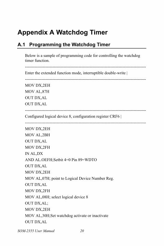
A.1 Programming the Watchdog Timer
Below is a sample of programming code for controlling the watchdog timer function.----------------------------------------------------------------------------------------Enter the extended function mode, interruptible double-write |----------------------------------------------------------------------------------------MOV DX,2EHMOV AL,87HOUT DX,ALOUT DX,AL----------------------------------------------------------------------------------------Configured logical device 8, configuration register CRF6 |----------------------------------------------------------------------------------------MOV DX,2EHMOV AL,2BHOUT DX,ALMOV DX,2FHIN AL,DXAND AL.OEFH;Setbit 4=0 Pin 89=WDTOOUT DX,ALMOV DX,2EHMOV AL,07H; point to Logical Device Number Reg.OUT DX,ALMOV DX,2FHMOV AL,08H; select logical device 8OUT DX,AL;MOV DX,2EHMOV AL,30H;Set watchdog activate or inactivateOUT DX,AL
SOM-2355 User Manual 20
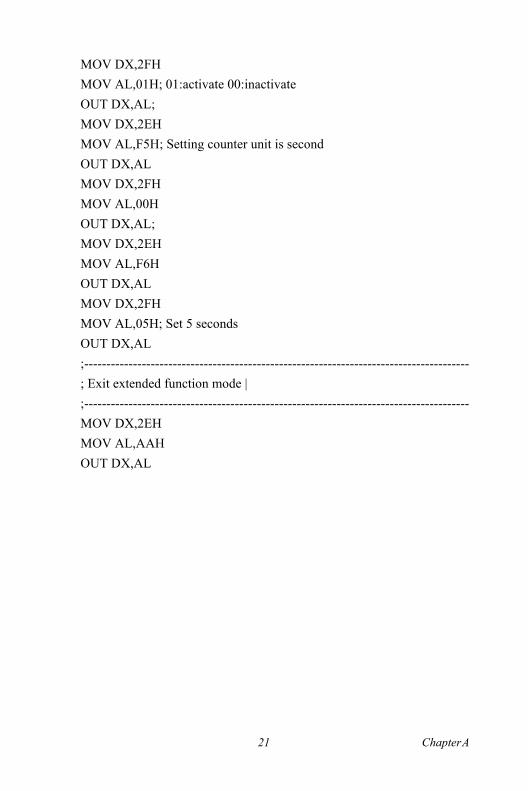
MOV DX,2FHMOV AL,01H; 01:activate 00:inactivateOUT DX,AL;MOV DX,2EHMOV AL,F5H; Setting counter unit is secondOUT DX,ALMOV DX,2FHMOV AL,00HOUT DX,AL;MOV DX,2EHMOV AL,F6HOUT DX,ALMOV DX,2FHMOV AL,05H; Set 5 secondsOUT DX,AL;---------------------------------------------------------------------------------------; Exit extended function mode |;---------------------------------------------------------------------------------------MOV DX,2EHMOV AL,AAHOUT DX,AL
21 Chapter A

SOM-2355 User Manual 22

BAPPENDIXSystem Assignments
This Appendix gives you the informa-tion about the system resource alloca-tion on the SOM-2355 CPU System on Module.Sections include:
� System I/O ports� DMA Channel Assignments� Interrupt Assignments
� 1st MB Memory Map
Appendix B System Assignments
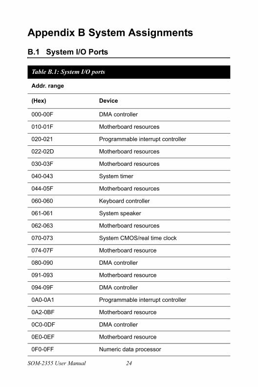
B.1 System I/O Ports
Table B.1: System I/O ports
Addr. range
(Hex) Device
000-00F DMA controller
010-01F Motherboard resources
020-021 Programmable interrupt controller
022-02D Motherboard resources
030-03F Motherboard resources
040-043 System timer
044-05F Motherboard resources
060-060 Keyboard controller
061-061 System speaker
062-063 Motherboard resources
070-073 System CMOS/real time clock
074-07F Motherboard resource
080-090 DMA controller
091-093 Motherboard resource
094-09F DMA controller
0A0-0A1 Programmable interrupt controller
0A2-0BF Motherboard resource
0C0-0DF DMA controller
0E0-0EF Motherboard resource
0F0-0FF Numeric data processor
SOM-2355 User Manual 24

170-177 Secondary IDE Channel
1F0-1F7 Primary IDE Channel
274-277 ISAPNP Read DATA Port
279-279 ISAPNP Read DATA Port
2F8-2FF Communications Port (COM2)
376-376 Secondary IDE Channel
378-37F Printer Port (LPT1)
3B0-3BA AMD WIN XP Graphic Driver
3C0-3DF AMD WIN XP Graphic Driver
3F6-3F6 Primary IDE Channel
3F8-3FF Communications Port (COM1)
4D0-4D1 Motherboard resource
778-77B Printer Port (LPT1)
A78-A7B Motherboard resource
B78-B7B Motherboard resource
BBC-BBF Motherboard resource
25 Chapter B

B.2 DMA Channel Assignments
Table B.2: DMA Channel Assignments
Channel Functions
0 Available
1 Available
2 Floppy disk (8-bit transfer)
3 Parallel**
4 Cascade for DMA controller 1
5 Available
6 Available
7 Available
** Parallel port DMA default setting: DMA 3, Parallel port DMA selection: DMA 1 or 3
SOM-2355 User Manual 26

B.3 Interrupt Assignments
Table B.3: Interrupt Assignments
Interrupt# Interrupt source
NMI Parity error detected
IRQ 0 System timer
IRQ 1 Keyboard
IRQ 2 Interrupt from controller 2 (cascade)
IRQ 3 Serial communication port 2
IRQ 4 Serial communication port 1
IRQ 5 Available
IRQ 6 Diskette controller (FDC)
IRQ 7 Parallel port 1 (print port)
IRQ 8 Real-time clock
IRQ 9 Reserve
IRQ 10 Available
IRQ 11 Available
IRQ 12 PS/2 mouse
IRQ 13 Numeric data processor
IRQ 14 Preliminary IDE
IRQ 15 Available
USB and Ethernet IRQ is automatically set by the system
27 Chapter B

B.4 1st MB Memory Map
Table B.4: 1st MB Memory Map
Addr. range (Hex) Device
E000h - FFFFh System ROM
CC00h -DFFFh Available
C000h - C7FFh VGA BIOS
B800h - BFFFh CGA/EGA/VGA text
B000h - B7FFh Reserved for graphic mode usage
A000h - AFFFh EGA/VGA graphics
0000h - 9FFFh Base memory
SOM-2355 User Manual 28