some in-field experiences of non-synchronous vibrations … · some in-field experiences of...
TRANSCRIPT

SOME IN-FIELD EXPERIENCES OF NON-SYNCHRONOUS VIBRATIONS
I N LARGE ROTATING MACHINERY
Giuseppe Colnago CES I
Via Rubattino 54 20134 M i lano, I t a l y
Claudio F r i g e r i , Andrea V a l l i n i , and Gian Antonio Zanetta ENEL
Via A . Vo l ta 1 20093 Cologno Monzese, M i lano, I t a l y
The paper analyzes some problems associated with non-synchronous vibrations by describing three cases experienced with fairly large rotating machines in operating conditions.
In each case, a brief description is first given of the machine and of the instrumentation used. The experimental results are then presented, with reference to time or frequency domain recordings. The lines followed in diagnosis are then discussed and, lastly, the corrective action undertaken is presented.
INTRODUCTION
Self-excited vibrations have always been a major concern in the field of the dynamics of rotating machinery, since they constitute a serious risk to the integrity of the machines, apart from leading to important losses in production.
In past years difficulties have mostly arisen from the fact that these problems were not well known and from a lack of appropriate experimental and analytical tools to cope with them. Nowadays, troubles are more often caused by the more exacting demands made of rotating machinery.
In any case, a great effort has always been made to identify these phenomena and to give them a proper theoretical description, with the result that an extensive literature now exists on the subject. However, most literature is still concerned with analytical investigations or laboratory tests, in which, of course, experiments are prepared in such a way that it is only possible to know parameters and to consider their influence one at a time.
But this does not apply to the diagnosis of real cases. As a matter of fact, in-field experience shows that, nearly always, a large
41
https://ntrs.nasa.gov/search.jsp?R=19890013523 2018-06-29T07:39:11+00:00Z

number of factors have to be taken into account at the same time, and it is neither easy to keep them apart nor to know or measure them exactly. Furthermore, when comparing one's own experimental measurements with references found in literature, one is faced with an inconsistent and rather confusing vocabulary and, for some topics, even by sharp discrepancies between different authors. All this, in turn, makes diagnosis more difficult and, sometimes, less definite.
The paper presents three case histories of sub-synchronous vibrations that recently occurred on fairly large rotating machines and in one way or another exemplify the above remarks. The first case regards the excitation of the first critical speed of an alternator rotor. The second concerns the hydraulic instability of a boiler feed- pump. The last one is about an instability with a component at exactly half the running speed on an H.P. turbine.
SUB-SYNCHRONOUS EXCITATION OF THE FIRST CRITICAL SPEED OF AN ALTERNATOR ROTOR
The machine was an alternator rotor weighing about 520 kN, supported by 2 cylindrical oil-film bearings,in service at a plant for short circuit tests: its operating speed ranged from about 4 7 to 62 Hz.
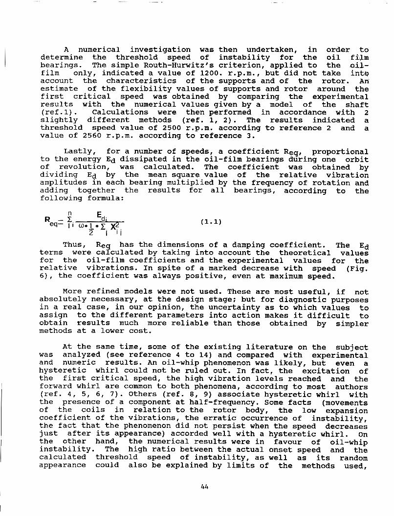
The machine had 2 eddy-current probes applied on each bearing. For our investigation 2 accelerometers were added on each bearing support and, together with a phase reference, all the signals provided by these transducers were recorded on a magnetic tape for subsequent digital analysis. It was thus possible to obtain the harmonic analysis of the vibrations throughout the speed range, the center loci of the journal in bearings, vibration orbits and spectrum analysis. Inlet and outlet oil temperatures at each bearing were also recorded.
Staff in charge at the plant and the manufacturer's technicians, reported that the rotor developed occasional sudden, very high vibration levels when spinning at maximum speed. Oil-film instability was immediately suspected. Nevertheless, tests on oil temperature failed to yield the usual results, since raising the oil temperature did not cause the phenomenontodisappear. On the contrary it seemed to grow a little worse. Although this could not lead to any definite conclusion about the nature of the instability, since it was only appearent at maximum speed, in case of oil-whip a higher oil temperature should have succeeded in making it disappear.
Owing to the specific features of the machine, it was possible to follow a number of run-ups and shut-downs and to keep it at maximum speed at different oil temperatures. The results of these tests may be summarized as follows:
~
-The machine had a number of critical speeds, with significant differences in the vertical and horizontal planes. The first critical
4 2

speed of the rotor was at about 1070 r.p.m. in the horizontal and at 1420 r.p.m. in the vertical plane. A 2nd critical rotor speed was most probably at about 3250 r.p.m. in the horizontal and quite near the maximum speed in the vertical plane. Other resonances might be attributed to flexibility of the supports and foundation and, for all of them, the phases indicated a 2nd vibration mode above 2000 r.p.m. (Fig. 1).
-The machine was in a rather poor balancing state for the 2nd vibration mode.
-The machine showed markedly non-repetitive behaviour when running at its first critical speeds, most probably due to considerable movement of the coils in relation to the rotor body.
-The centre loci of journal in bearings showed that, at the higher speeds, the shaft moved strongly towards the bearing centre (Fig. 2).
Specifically as regards instability, the following point may be made :
-During the investigation the phenomenon was observed only once, which confirmed its purely random nature. Moreover, no definite link with oil temperature could be established.
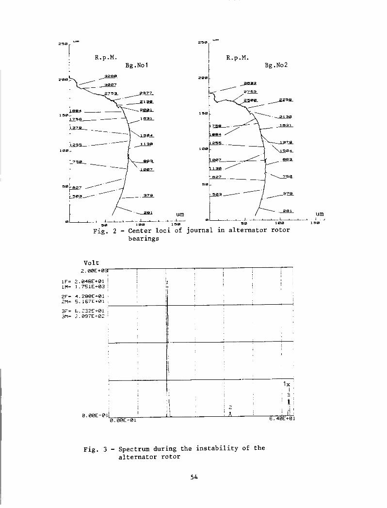
-In the presence of the phenomenon, the high vibration levels were mainly determined by a sub-synchronous vibration component at 20.4 Hz (1250 r.p.m.), while running speed frequency was 62.4 Hz (3750 r.p.m.). Maximum amplitude was reached by relative displacement in the horizontal plane and was of about 650 pmpp, very close to total bearing clearance at the design stage. A number of much smaller harmonics of that component were also found and were considered to be due to non-linear behaviour of the oil film (Fig. 3). Though it almost coincided with 1/3 of the running speed, the frequency of the sub-synchronous component was considered as corresponding to excitation of the first critical speed of the rotor in those conditions.
-When filtering signals around the sub-synchronous component at 20.4 Hz, it was observed that the growth of these vibrations was rather slow and during some cycles they even kept stable (Fig. 4). The expansion coefficient, equivalent to a critical damping coefficient for the introduction of energy, was found to be equal to 0.005, taking into account the logarithmic increment. The orbits showed that the journal fol1owed.a forward whirl. Figure 5 shows a subsequent series of orbits.
-The instability disappeared as soon as the running speed of the rotor was lowered, developing and disappearing in the space of about 10 seconds.
-At maximum speed, a small component at about 20.4 Hz was always present, but appeared and disappeared conthously without reaching a significant level, when the instability did not develop fully.
4 3
A numerical investigation was then undertaken, in order to determine the threshold speed of instability for the oil fi,lm bearings. The simple Routh-Hurwitz's criterion, applied to the oil- film intcp account the characteristics of the supports and of the rotor. An estimate of the flexibility values of supports and rotor around the first critical speed was obtained by comparing the experimental results with the numerical values given by a model of the shaft (ref.1). Calculations were then performed in accordance with 2 slightly different methods (ref. 1, 2). The results indicated a threshold speed value of 2500 r.p.m. according to reference 2 and a value of 2560 r.p.m. according to reference 3 .
Lastly, for a number of speeds, a coefficient Req, proportional to the energy Ed dissipated in the oil-film bearings during one orbit of revolution, was calculated. The coefficient was obtained by dividing Ed by the mean square value of the relative vibration amplitudes in each bearing multiplied by the frequency of rotation and adding together the results for all bearings, according to the following formula:
only, indicated a value of 1200. r.p.m., but did not take
n E
Thus, Req has the dimensions of a damping coefficient. The Ed terms were calculated by taking into account the theoretical values for the oil-film coefficients and the experimental values for the relative vibrations. In spite of a marked decrease with speed (Fig. 6), the coefficient was always positive, even at maximum speed.
More refined models were not used. These are most useful, if not absolutely necessary, at the design stage; but for diagnostic purposes in a real case, in our opinion, the uncertainty as to which values to assign to the different parameters into action makes it difficult to obtain results much more reliable than those obtained by simpler methods at a lower cost.
At the same time, some of the existing literature on the subject was analyzed (see reference 4 to 14) and compared with experimental and numeric results. An oil-whip phenomenon was likely, but even a hysteretic whirl could not be ruled out. In fact, the excitation of the first critical speed, the high vibration levels reached and the forward whirl are common to both phenomena, according to most authors (ref. 4, 5, 6, 7). Others (ref. 8 , 9) associate hysteretic whirl with the presence of a component at half-frequency. Some facts (movements of the coils in relation to the rotor body, the low expansion coefficient of the vibrations, the erratic occurrence of instability, the fact that the phenomenon did not persist when the speed decreases just after its appearance) accorded well with a hysteretic whirl. On the other hand, the numerical results were in favour of oil-whip instability. The high ratio between the actual onset speed and the calculated threshold speed of instability, as well as its random appearance could also be explained by limits of the methods used,
44

uncertainties in the parameters introduced (wear, angular misalignment), actual oil temperature in bearings (ref. 10) and effects of synchronous excitation. On this last subject, significant disagreements were found in literature (compare references 5, 11, 12, 13). Other tests suggested by some authors (ref. 6) to improve the diagnosis could not in practice be performed on a machine of that size.
Luckily, both phenomena could be obviated by the same remedial action, by substituting partial arc bearings (with an arc of 60 degrees) for the existing cylindrical ones. The threshold speed for the new kind of bearings was found to be about 4000 r.p.m., according to the above-mentioned methods. Furthermore, the new bearings introduced a larger asymmetry between the horizontal and vertical planes in bearing characteristics. This should have improved stability for both phenomena under examination (ref. 5, 14). Moreover, calculations were performed with a model of the rotor, to evaluate the power loss in the oil film with cylindrical and partial arc bearings. Excitation of the 1st and 2nd vibration mode were considered separately, at both critical and maximum speeds. In all cases, the amount of dissipated energy in one orbit of revolution was greater for partial arc bearings, whose only drawback was to increase the horizontal vibrations. This low-cost solution was finally implemented and gave the expected results. So far, this problem has no longer reappeared.
SUB-SYNCHRONOUS VIBRATIONS ON A BOILER FEED PUMP
The problem was encountered on one of the 9 boiler feed-pumps of identical design installed in a thermal power plant with four 320 MW turbogenerator units. These centrifugal pumps had 5 stages with plain interstage seals and grooved seals at the glands and on the balancing- drum. The operating speed ranged from 4200 to 6200 r.p.m., the maximum capacity and pressure being 640 Tons/h and 18 MPascal, respectively. The pump was driven by an electric motor, and the power was transmitted through a gear mesh, controlled in turn by 4 hydraulic units. After a few years of normal operation the pump in question began to register high vibrations, so that it could no longer be kept in service.
In an initial set of measurements by the manufacturer, spectrum analysis revealed the presence of a subsynchronous component at about 95 per cent of the rotational speed. It was reported that the fault was more likely to occur below a certain pump capacity, yet was not repeatable under seemingly the same conditions. No conclusions were drawn as to its causes. The machine was then considered as a spare pump, but its behaviour was most unreliable and, after some other unsuccessful attempts to get it to work, a deeper investigation was called for.
First of all an excitation test was performed with the machine at rest. The force was applied on one bearing support by a sinusoidal
45

sweep over the frequency range in question; measurement points were set up on both bearing supports, on the casing and on the pump foundation. In the horizontal plane, 2 distinct maxima in the response were observed at about 95 and 110 Hz, butthey were strongly damped and the measured compliance was not greater than 600 pm/kN. No
important structural problems could be ruled out. specific information was obtained for the vertical plane. so
Then the machine was fitted with 2 eddy-current probes at each bearing, a pressure transducer on the delivery side of the pump, a phase reference on the shaft, while retaining 2 accelerometers on each support, and 3 other accelerometers on the foundation and on the driving unit. The signals so obtained, together with the capacity signal, were recorded on a magnetic tape for subsequent analysis.
The aim of the tests was to find out which parameter, such as capacity, rotational speed, pressure, or which combination of them, could start the phenomenon. In fact, the anomalous behaviour of the pump and the very high vibrations prevented from achieving the planned program in an orderly way. The following remarks may be made:
-The highest vibration levels were reached in the horizontal direction on both bearings, with a maximum on the bearing next to the electric motor. The foundation and the driving units were only marginally affected by the vibration.
-The pump was in poor balancing state with synchronous vibrations far beyond admissible levels. Recordings at variable speed showed a possible resonance at 6000 r.p.m. in the horizontal plane, but with a low amplification factor and deformation shape in the 2nd vibration mode.
-The instability developed in no more than 10 cycles and, once fully established, the vibration was not steady (Fig. 7).
-Spectrum analysis during the instability indicated that, in such conditions, the vibration was mostly determined by a sub- synchronous component whose frequency ranged from 0 . 8 5 to 0.97 of the running speed (Fig. 8, 9). The frequency of this component was not related to the rotational frequency, nor to the pressure or to the flow rate, as evidenced in figure 8, where the spectrum, obtained by a peak-hold average on only one time record 5 seconds long, showed 3 sub-synchronous components with different frequencies.
-With lower pressure at delivery it was possible to reach the maximum flow rate, but at that point the instability showed up again and vibrations up to 400 pmpp were reached on that occasion.
-By correlating the support vibrations with frequency responses to external excitation, it was possible to get a rough estimate of the forces in play. These reached 30 k N on the supportnext to the coupling end with the motor.
46

-An auxiliary mass damper, tuned to the middle of the frequency range in question, was added in order to introduce some damping into the system, but that was not enough to suppress the instability. Under those circumstances, when the instability appeared, it was calculated from the displacement of the support to which the damper was attached that the inertial force of the auxiliary mass was about 7 kN.
-Moreover, relative vibration values at the bearing locations greater than clearances and the deformation shape of the shaft at those frequencies indicated the possibility of significant wear in one bearing and in some seals.
By comparing these experimental results with the literature available on the subject (ref. 15, 16, 17), a diagnosis of hydraulic instability was arrived at. Most likely, it was due to forces generated by the interaction of diffuser and impeller, on which a negative influence could be exerted by the generally bad conditions of the pump (balancing state or bent shaft and wear). Contrary to what is stated in references 16 and 17, the problem was also present at high flow rates.
Initially, a general overhaul of the pump was suggested; but changes of bearings and to some details in seals or clearances between impeller and diffuser, even at the cost of somewhat reduced efficiency, were considered essential. The machine was opened and, in fact, the bearing next to the coupling end and a number of seals, especially on the balancing drum, were found to be badly damaged. After maintenance, the pump was restarted again in the original design condition, since the changes suggested had not been completely defined. During the first tests and for a little while after, it looked as though the instability had disappeared. But afterwards, it reappeared again. So,in spite of proper diagnosis, it had not thus far been possible to get rid of the problem.
EXACT HALF FREQUENCY WHIRL IN AN H . P . TURBINE ROTOR
The machine in question was an H . P . turbine in an old 70 MW turbogenerator unit. The 3 rotors, H . P . and L.P. sections and the generator, were supported on 6 cylindrical bearings. The H . P . rotor weighed about 90 kN. The seal-rings of the steam glands were made of steel and very stiff. The operating speed was 3000 r.p.m.(50 H z ) .
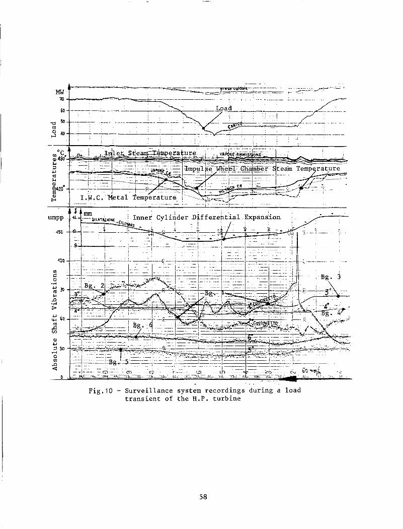
Two months after overhaul, the H . P . rotor showed a sudden increase in vibration in bearing No 1, after load reductions during normal operation. Surveillance instruments showed the phenomenon as a sharp peak in the overall absolute shaft vibration of that bearing only, the other bearings being apparently unaffected (Fig. 10). Moreover, the phenomenon only lasted a few minutes, then disappeared without tripping the unit. It was preceded by a continous increase in vibration level at the same bearing, starting with the load reduction
47

transient and in good correlation with metal and steam temperature changes in the impulse wheel chamber. It is worth adding that load reductions were achieved by partialization of steam admission.
Since then, a rubbing effect had been suspected. Detailed investigation was therefore decided on and the absolute shaft vibration at the 6 bearings plus the support vibration at each of the four turbine bearings, plus a number of other quantities (metal and steam temperatures, active and reactive power, vacuum of the condenser, oil temperatures) were collected by a digital acquisition system able to carry out the harmonic analysis after a synchronous acquisition. Furthermore, it was possible to store 4 channels of time history data for subsequent spectrum analysis. Although they would have proved very useful on such an occasion, eddy-current probes could not be used until the machine was stopped.
A few tests were devised with the machine still in service. First of all, the operation sequence that had given rise to the phenomenon (load reduction from 70 MW to about 47 MW) was repeated, being careful to start from and to arrive at steady thermal conditions. In fact, the phenomenon appeared again, in almost the same way as shown in figure lo. Frequency analysis indicated that, during the first phase of load and thermal transient, vibration rises at bearing No 1 were caused mostly by a fundamental component of the signal, and 2nd harmonic variations appeared after a certain vibration level, probably due to non-linearities in the oil film. When the fundamental component arrived at about 90 pmpp a sub-synchronous component became visible; but it was not yet stable and it appeared and disappeared suddenly between one series of orbits of revolution and another. With a further increase in the fundamental component over 100 pmpp, the phenomenon continued to be present and the sub-synchronous vibration stabilized on a definite value (Fig.11). Values as high as 200 pmpp were read for this component. In any case, its frequency was 25 Hz, exactly half the frequency of the running speed. Moreover, higher harmonics at 75 and 125 Hz were present, the others, at 50 and 100 Hz, being hidden in the fundamental and 2nd harmonic components. The 25 Hz component was very low for the absolute shaft vibration at bearing No 2, while it was marked on both supports of bearings No 1 and No 2. Finally, when the thermal transient died out and the vibration decreased to below the above-mentioned levels, the sub-synchronous component disappeared.
The same test was repeated with the oil temperature in bearings 7 Oc higher, but gave the same results. This time, with the machine at a 4 7 Mw output and after reaching steady thermal conditions, a 40 OC drop in the inlet steam temperature again caused a vibration rise and, in turn, the sub-synchronous component made its appearance once more.
An analysis of bearing data showed that bearing No 1 was underloaded and the first critical speed was found to correspond to about 2000 r.p.m. ( 3 3 Hz) by a model of the shaft line, at least when in theoretical alignment. If the stiffness of bearing No 1 was reduced significantly, as it could be for the partialization effect, the turbine behaved like a cantilever. In this way, the critical speed might be less than 25 Hz and the deformation might resemble that
48

corresponding to the experimental measurements of the component at 25 Hz .
At this point, an oil whirl instability was ruled out, because the latter is characterized by a frequency content that is always slightly less than exactly half the rotational speed (ref. 5). The rise in oil temperature did not affect the phenomenon, which appeared only after the synchronous vibrations had reached a high level. In most authors' opinions, as already mentioned in the first case history, high vibrations snould counteract oil whirl instability. Moreover, time recordings made here were not typical of that kind of instability.
On the contrary the lifting of the rotor for partialization effects, the shaft bending due to the thermal transient and the increase in the vibrations themselves were enough to explain a light rubbing effect, causing instability of a parametric kind, or due to friction forces, with a sub-synchronous frequency content equal to exactly half the rotating speed and its harmonics, like that described in references 18 or 19. However, the results referred to in these papers stem from theoretical developments and the experimental evidence given in reference 19 is limited to a small model. According to other authors (ref. 20), subharmonic components are unlikely to be found in actual turbogenerator sets and, as far as we know, only very few cases have been reported (ref. 21, 22). Vibration orbits might have made a definite opinion possible, but unfortunately they were not available.
In an initial attempt, it was suggested the turbine case be raised by 0.2 mm in relation to the rotor. The operation sequence able to produce the fault was repeated and this time only a little track of the subsynchronous component around 25 Hz in the presence of the fundamental component vibration levels was found.
During a subsequent short overhaul, the seal-rings were replaced by others of a much more flexible type and the clearances were finally revised. The problem has not so f a r reappeared. The rotor naturally maintained high sensitivity to thermal transients and to partialization effects. In order to reduce the influence of such effects, it was suggested that the cylindrical bearing be replaced by a tilting-pad bearing or, at least, be shortened, to increase the equivalent load. This action, however, though scheduled, has not yet been put into effect.
CONCLUSIONS
Three different in-field experiences of instability problems that occurred in large rotating machines under operating conditions have been discussed. Two of them were not so common and are scarcely referred to in literature, at least as in-field cases.
49

The lines followed in the diagnostic process have been emphasized. It has been shown that frequency analysis alone is not always enough to perform a definite diagnosis, since different phenomena often give rise to the same, or almost the same, frequency content. Knowledge of the structural characteristics of the whole mechanical system and the correlation of vibrations with other quantities are usually necessary, as well as comparison with other experiences and studies. Mathematical models, too, may prove very useful as an aid to diagnosis.
Once the problem has been correctly identified, the subsequent remedial action is often quite straightforward. In other cases, the complexity of the phenomena calls for special effort,and good results can be achieved only if it is possible to delve deeper into design details and experimentation.
REFERENCES
1.
2.
3.
4.
5.
6.
7.
DYTS04-USER'S GUIDE-CEGB-RD/L/P 15/80-JOB NO. VE316
Mechanical Technology Incorporated Rotor-Bearing Dynamics Design Technology-Part 111: Design Handbook for Fluid Film Type Bearings. Technical Report AFAPL-TR-65-45, PART I11 - May 1965 Glienicke, J. Experimentelle Ermittlung der statichen und dynamischen Eigenschaften von Gleitlagern fur schnellaufende Wellen. VDI Zeitschriften, Reihe 1, Nr. 22, Aug. 1970
Tondl, A. Some Problems of Rotor Dynamics. Publishing House of the Czechoslovak Academic of Sciences, Prague-1965
Rieger, N.F. Stability of Rotors in Bearings-4 Lectures. CISM, Udine-Rotordynamics Colloquium-October 12:16, 1980
Bentley , D. E. The Re-Excitation of Balance Resonance Regions by Internal Friction. ASME paper No. 72-Pet-89 EPRI CS-3716-Project 1648-5-Final Report-September 1984
Sacchi, G.-Moro, B. Vibratory Problems on Gas Turbine Rotors. IFToMM-International Conference 'Rotordynamic Problems in Power Plants'- September 28-October 1, 1982-Rome-Italy
50

8. D'Ans, G.-Vanlerberghe,C.-Geradin, M.-Pirlot, A.-Suleau, M. Some Case Studies of Modal Analysis, Signature Analysis and Finite Element Modelling. VibraRoMa Meeting-Milan-Italy-September 1981
9. Harris, C.M.-Crede, C.E. Shock &I Vibration Handbook McGraw-Hill Book Company-2nd Edition-1976
10. Wagner, L.F.-Raimondi, A.A. Effect of Oil Film Properties and Support Characteristics on Oil- Whip Instability. EPRI CS-4024-Contract WS 81-240-Proceedings-June 1985
11. Barret, L.E.-Akers, A.-Gunter, E.J. Effect of Unbalance on a Journal Bearing Undergoing Oil Whirl. Proc. IMech E-Vol.190 31/76
12. Bannister, R.H. The Effects of Unbalance on Stability and Its Influence on Nan- Synchronous Whirling. IMech E-2nd International Conference 'Vibrations in Rotating Machinery' 1980-Paper No. C310/80
13. Adams, M.L.Jr. Large Unbalance Vibration Analysis of Steam Turbine Generators. EPRI CS-3716-Project 1648-5-Final Report-September 1984
14. Inoue, T.-Matsukura, Y. Effect of Bearing Asymmetry on the Motion of an Asymmetric Rotor. Proc. of the 27th Japan National Congress for Applied Mechanics, 1977
15. Black, H.F. Lateral Stability and Vibrations of High Speed Centrifugal Pump Rotors. IUTAM Symposium 'Dynamics of Rotors'-Lyngby/Denmark 1974
16. Makay, E. Centrifugal Pump Hydraulic Instability EPRI CS-1445-Research Project 1266-18-Final Report-June 1980
17. Brown, R.D. Vibration Phenomena in Boiler Feed Pumps Originating from Fluid Forces. IFToMM-International Conference 'Rotordynamic Problems in Power Plants'- September 28-October 1, 1982-Rome-Italy
18. Childs, D.W. Fractional-Frequency Rotor Motion Due to Nonsymmetric Clearance Effects . Journal of Engineering for Power-July 1982, Vo1.104/533
51

I 19.
20.
21.
,
22.
Muszynska, A. Partial Lateral Rotor to Stator Rubs. IMech E-Third Int. Conference in 'Vibrations in Rotating Machinery'-ll:13 September 1984-University of York-Heslington, Yorkshire
Curami, A.-Pizzigoni, G.-Vania, A. On the Rubbing Phenomena in Turbomachinery. IFToMM-International Conference on 'Rotordynamics'-September 14- 17, 1986, Tokyo
Benanti, A.-Gadda, E. Analysis of Turbogenerator Malfunctioning on the Basis of Vibrational Behaviour. 6th Thermal Generation Specialists Meeting-Madrid, May -56, 1981
Gao Jin Ji-Qi Qi Min Rotor to Stator Rub Vibration in Centrifugal Compressor. Synposium on 'Instability in Rotating Machinery'-Carson City, June 10-14, 1985-NASA Conference Publication 2409
5 2

Bg. Nol-Support Vibration
R. p. m. 4088 s000 a m m m
e m
e m -
a m 0 0 ' s . . . . * . . . - a . *
1008 2 0 m e
Grcrd i Horizontal Vibration: lee-
Vertical Vibration : - , R. p. m.
2 m 0 m a m m m 4 m 0 m s m m m e m 0 m
Bg. Nol-Relative Vibration
c e m -
t r o d 1 Horizontal Vibration:
I I
Vertical Vibration :r - ?
I , _cf- R. Q. ---. . .
4880 s m m m e m m m
Fig.1 - Speed transient of the alternator rotor
53
R.p .M. Bg .No2
urn
R.p.M. : Bg.Nol
200 - 3260 7
150 - 150- zse-~ -
1 0 0 -
750
urn -1- L...--l- --I--- L A
sa 100 1 sa
urn
Fig. 2 - Center loci of journal in alternator rotor 1 I L-_I-A_l---L--l--l
ea i ma 1 sm
bearings
Fig. 3 - Spectrum during the instability of the alternator rotor
54

I I I
T- 4.00006 s
Fig.4 - Development of t h e i n s t a b i l i t y on t h e a l t e r n a t o r r o t o r
I
1 7---7-7
5
2 3 4 '0' 4
6
7
10 1 1 l_i_
1 2
Fig.5 - Journa l o r b i t s i n bea r ing No1 during t h e i n s t a b i l i t y of t h e a l t e r n a t o r r o t o r
55

Fig.6 - Equiva len t damping c o e f f i c i e n t a t d i f f e r e n t speeds of t h e a l t e r n a t o r r o t o r
F ig .
. . . . . . 1 .__. ..-I-- I4 -
1 sec Ch.1: F i l t e r e d Synchronous Vib ra t ion Ch.2: U n f i l t e r e d V i b r a t i o n
7 - Development of t h e i n s t a b i l i t y i n t h e b o i l e r f e e d -pump
56

17.. E-
1 : Support No 1-Horizontal 2: Support No 2-Horizontal
,
\
I
I I
I
I
Vibration Vibration
Fig. 8 - Typical spectrum analysis during the instability of the boiler feed pump
Fig 'SUS the :r feed-pump
57
120
_-
-
Fig.10 - S u r v e i l l a n c e system r e c o r d i n g s d u r i n g a l o a d t r a n s i e n t of t h e H.P. t u r b i n e
58

"I
.I
Inc i p i e n t Phenomenon -="' 1/2x 1x 3/2X
-- - - - - - 20 40 66" 80 100 120 WIO.
Ful ly Developed Phenomenon 1 / 2 X 1X 3/2X "I u-,
-I. . YO_.. ._ I .. -. - - -
Y.
-.- - - - - 20 40 80 100 120 - .L
V 1 , V2: Absolute Shaf t Vibra t ions S I , S2: Support V e r t i c a l Vibra t ions
Fig.11 - Time records and spectrum a n a l y s i s i n t h e i n s t a b i l i t y of t h e H.P. t u r b i n e
59