some thoughts for the geometric design of calibration fields · • for aerotriangulation the...
TRANSCRIPT

Universität Rostock, Professur für Geodäsie und Geoinformatik X 2009
Some thoughts for the geometric design of calibration fields
Görres Grenzdörffer
EuroDAC²-Meeting Barcelona 1.4. – 2.4.2009
Universität Rostock, Professur für Geodäsie und Geoinformatik
General remarks I
• The most important factors for the development of a test field for geometric calibration are the size, distribution, positional accuracy, and number of reference targets. The height differences within a test field are also important, but a lack of height differences may be overcome with flights in different elevations.
• In the digital world more GCP’s are necessary to fully describe and calibrate the system performance than in analogue times !
• This is due to the fact that the geometric calibration procedure(aerotriangulation) should not only determine the parameters of the exterior orientation, but also (re)calibrate the interior orientation, perform the bore site alignment, identify datum defects, errors due to forward motion compensation, errors due to errors of the single camera heads, etc.

Universität Rostock, Professur für Geodäsie und Geoinformatik
Introductionary remarks
• Clients demand for higher resolutions (3 – 10 cm/ pixel) and drive the camera systems to their limits. However the higher the ground resolution of the images the more accurate a calibration has to be.
• Future camera systems will have higher resolution / more pixels• For aerotriangulation the positional accuracy of the GCP’s should
be determined with accuracy 10 times higher than the pixel resolution. Commonly the accuracy of the GCP’s of existing test fields is 1 cm or less. In the future we will need an accuracy of 1 mm – 1 cm !!
• This demand may not be fulfilled with manual measurements of GCP’s.
Universität Rostock, Professur für Geodäsie und Geoinformatik
Extended calibration requirements - additional parameters
• Self calibration with additional parameters is necessary. This is especially true for small blocks and a limited number of GCP’s.
• Additional parameters• Additional parameters allow for the determination and compensation
of systematical errors, which are not covered by the standard model. Additional parameters for large format camera systems generally cover alignment and calibration errors of the different single camera heads which form the final image. Furthermore errors resulting from datum definition problems, GPS/INS misalignment etc. may be covered with additional parameters. Additional parameters lead toward unambiguous and more accurate results.
•• However they also reduce redundancy and thus the reliability of However they also reduce redundancy and thus the reliability of the the resultsresults..

Universität Rostock, Professur für Geodäsie und Geoinformatik
Goals
• In order to speed up calibration procedures a fully automated workflow has to be developed
Automated steps
Manual steps*
Image post processing
ATManual GCPcollection
Quality assessment
Calibration
Calibrationprotocol
Residuals
Image post processing
ATAutomatic GCPcollection
Quality assessment
Calibration
Calibrationprotocol
Residuals
* Missing rules for automation
Universität Rostock, Professur für Geodäsie und Geoinformatik
Open questions prior to geometric design of test range
• Q: What is the range of GSD covered with the test field ?• A: For calibration of large and medium format cameras in Europe
5 – 20 cm GSD• Q: What is the typical GSD for calibration ?• A: 5 – 10 cm GSD• Q: What factors shall be calibrated in a single calibration flight,
e.g. on the job calibration of GPS/INS, interior orientation, single camera head calibration, FMC-influence on image sharpness, color fringes and chromatic aberration, etc.
• A: Different test designs will allow for different calibration procedures
Universität Rostock, Professur für Geodäsie und Geoinformatik
Simple calibration flight configuration
Side lap 60 – 80 %
End lap 60 – 80 %
• Simple calibration scenario• Well suited for bore site alignment and determination of local datum
defects• Interior orientation is known• GSD of calibration = GSD of image flight• Calibration valid for this flight only• Ideal configuration in the vicinity of airfield
Universität Rostock, Professur für Geodäsie und Geoinformatik
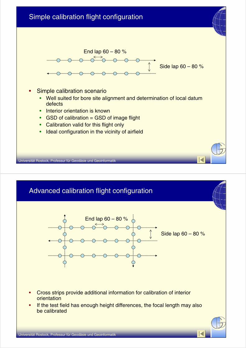
Advanced calibration flight configuration
• Cross strips provide additional information for calibration of interior orientation
• If the test field has enough height differences, the focal length may also be calibrated
Side lap 60 – 80 %
End lap 60 – 80 %

Universität Rostock, Professur für Geodäsie und Geoinformatik
Advanced calibration flight configuration for flat test ranges
• Flights at two different altitudes allow for in depth calibration of focal length, and other systematical errors
Side lap 60 – 80 %
End lap 60 – 80 %
low altitude
high altitude
Universität Rostock, Professur für Geodäsie und Geoinformatik
Ground control points (GCP) (=signalized targets)
• Former OEEPE and EuroSDR tests revealed that the most labourintensive and error sensitive step in geometric calibration is the manual determination of GCP’s. The determination of the GCP’sshould therefore be automated in the future to speed up the process and enhance the reliability of the calibration
• For a human operator the signalized point should have a size of min. diameter of 3 pixel in the image. The accuracy of the humanoperator is approx. 0.2 – 0.3 pixel.
• This is limiting the accuracy of the AT and the geometric calibration for fine GSD.
• The size of a GCP on the ground should not exceed 1 m.• The accuracy of automated operators is between 0.005 – 0.1
pixel, thus approx. 2 - 60 times higher than the human operator• For automatic target centroid detection the target must be round
and larger than 5 pixel. The optimal size is 5 – 25 pixel in diameter.

Universität Rostock, Professur für Geodäsie und Geoinformatik
Accuracy potential of automated target measurement strategies in relation to GCP size
Accuracyin Pixel
Diameter(Pixel)
5 10 15 20 25
Ellipse Ellipse operatoroperatorLeast Least squaresquare
CentroidCentroid
Elli
pse
Elli
pse
oper
ator
oper
ator
Leas
t Le
ast s
quar
esq
uare
Cen
troi
dC
entr
oid
0.005
0.01
0.02
0.10
0.05
• The bigger the target, the more accuratethe measurement
• Minimum size for automated targetmeasurement = 5 pixel
• Max. GSD for 1 m target = 20 – 22 cm
• The bigger the target, the more accuratethe measurement
• Minimum size for automated targetmeasurement = 5 pixel
• Max. GSD for 1 m target = 20 – 22 cm
Source: Luhmann, 2003
Universität Rostock, Professur für Geodäsie und Geoinformatik
Coded GCP‘s for fully automated AT
• For further fully automation of the triangulation coded targets may be used. The code, formed by a certain pattern allows for an automatic determination of the point and the associated coordinate.
• Coded targets would be nice, but they are not necessary for GPS/INS supported flights, because the approximate position GCP’s may be determined with forward resection.
• Coded targets are an opportunity for < 5 cm GSD calibration flights (1 m target = 20 pixel)

Universität Rostock, Professur für Geodäsie und Geoinformatik
Template for circular GCP
Max. diameter 1 m
• Foam or wooden template for painting or spraying the GCP on the ground
• Two hairlines form a cross to determine the center, which may measured with high accuracy
• Due to high object contrast the GCP will appear bigger in the resulting image, factor 1 – 1.5
• Resulting size of template for GSD of 3 - 20 cm 7 - 32 Pixel
Universität Rostock, Professur für Geodäsie und Geoinformatik
Template for circular GCP for two resolutions
Max. diameter 1 m
• Advantage• Targets for different sensors or
images acquired at different altitudes may be analyzed with the same GCP’s
• Disadvantage• For very coarse GSD the object
contrast inner circle will bloom the outer circle and reduce the visibility of the whole target.
Universität Rostock, Professur für Geodäsie und Geoinformatik
Template for circular GCP with Siemens star
• For photogrammetric work the outer edge of the circle will be used to determine the GCP center
• The inner siemens star resolving power,
• Advantage• Geometry and resolution
information in one step
• Disadvantage• Will not work with coarse
GSD
• Maintenance of Painting
Max. diameter 1 m
Universität Rostock, Professur für Geodäsie und Geoinformatik
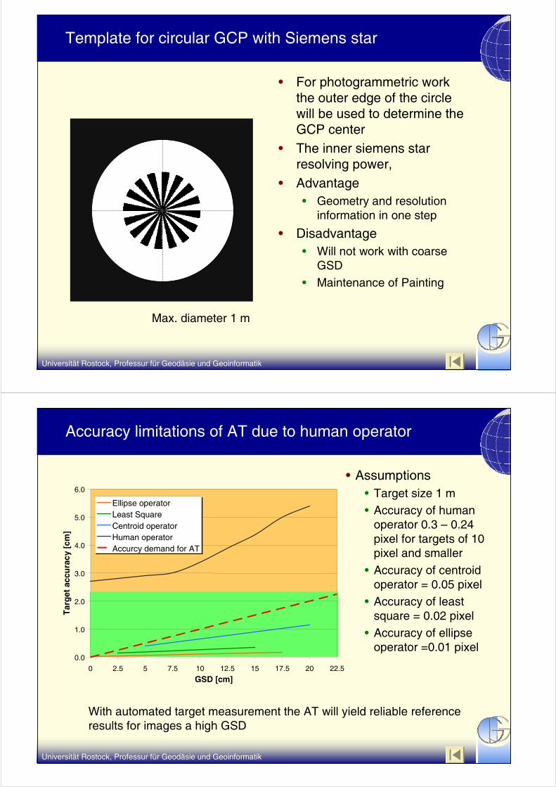
Accuracy limitations of AT due to human operator
• Assumptions• Target size 1 m• Accuracy of human
operator 0.3 – 0.24 pixel for targets of 10 pixel and smaller
• Accuracy of centroidoperator = 0.05 pixel
• Accuracy of least square = 0.02 pixel
• Accuracy of ellipse operator =0.01 pixel
With automated target measurement the AT will yield reliable referenceresults for images a high GSD
0.0
1.0
2.0
3.0
4.0
5.0
6.0
0 2.5 5 7.5 10 12.5 15 17.5 20 22.5
GSD [cm]
Tar
get
accu
racy
[cm
]
Ellipse operatorLeast SquareCentroid operatorHuman operatorAccurcy demand for AT

Universität Rostock, Professur für Geodäsie und Geoinformatik
0
2000
4000
6000
8000
10000
12000
14000
16000
18000
2.5 5 7.5 10 12.5 15 17.5 20 22.5 25 27.5 30
GSD [cm]
Tes
t R
ang
e L
eng
th[m
]
UltraCAM XDMCRollei AIC45FutureCam
0
2000
4000
6000
8000
10000
12000
14000
16000
18000
2.5 5 7.5 10 12.5 15 17.5 20 22.5 25 27.5 30
GSD [cm]
Tes
t R
ang
e W
idth
[m]
UltraCAM XDMCRollei AIC45FutureCam
Test range extend for several sensors and different GSD
• Assumptions• Length of test range 10 images with 80 % end lap• Width of test range 3 strips with 60 % side lap
• „FutureCam“ (20.000 x 25.000 pixel, 5 μm pixel size)
..10..
To cover future very high resolutions sensors with coarse GSD, large test ranges of 10 * 15 km are necessary
Universität Rostock, Professur für Geodäsie und Geoinformatik
Test range dimension for airborne companies performing standard calibrations
• Assumptions• Length of test range 10 images with 80 % end lap• Width of test range 2 strips with 60 % side lap
• „FutureCam“ (20.000 x 25.000 pixel, 5 μm pixel size)
..10..
0
2000
4000
6000
8000
10000
12000
2.5 5 7.5 10 12.5 15 17.5 20 22.5 25 27.5 30
GSD [cm]
Tes
t R
ang
e L
eng
th [
m]
UltraCAM XDMCRollei AIC45FutureCam
0
2000
4000
6000
8000
10000
12000
2.5 5 7.5 10 12.5 15 17.5 20 22.5 25 27.5 30
GSD [cm]
Tes
t R
ang
e W
idth
[m
]
UltraCAM XDMCRollei AIC45FutureCam
With current sensors and common GSD ≤ 20 cm a test ranges of 4 * 4 km are necessary

Universität Rostock, Professur für Geodäsie und Geoinformatik
Proposed GCP configuration for 3 flight line configuration with independent quality check (for 1 sensor and elevation)
GCP‘s for AT
Independent GCP‘s for AT-quality
GCP-cluster for• Single camera cone
calibration• Resolving power and
FMC calibration
Universität Rostock, Professur für Geodäsie und Geoinformatik
Calibration of optical resolving power incl. FMC, TDI etc.
• The optical resolving power is an important quality parameter for the user, thus giving him information of the image quality. The optical resolving power changes, due to the flight conditions
• The optical resolving power decreases from the center to the edges, also multi head cameras are affected !!
• The optical resolving power depends on the contrast of the line pattern in object space. That means: optics (lens fall of, spherical and chromatic aberrations), aperture, FMC / TDI, atmosphere, flying height, “development” of the digital image etc., will influence the final optical resolving power for user.

Universität Rostock, Professur für Geodäsie und Geoinformatik
Calibration of optical resolving power incl. FMC, TDI etc.
• To conclude it is necessary to measure the revolving power for various field angles, for radial and tangential directions and for flight and cross-flight directions. This is especially true for medium format cameras which generally do not have a FMC.
Resolving Power (lp/mm)
MT
F (
Co
ntr
ast)
1.0
0.0
0.2
0.4
0.6
0.8
20 40 60 80 100
low
mediumhigh
Example of angular resolvingpower falloff due to wrong airspeed/GSD settings or lack of FMC
Universität Rostock, Professur für Geodäsie und Geoinformatik
Calibration of optical resolving power incl. FMC, TDI etc.
• Calibration targets either Siemens stars or high contrast lines (much easier to handle) This target should include patterns with sufficiently fine detail. Popular targets are resolution bars, edges, and Siemens star targets.
• High contrast edges must be visible in several parts of the image and in different angles. Use of either natural targets (Shadows, roof tops) or artificial targets
• The edge targets have to have minimum length of 10 pixel
BiggestBiggest problemproblem forfor calibrationcalibration: Image : Image processingprocessing stepssteps, , ThereThere isis no such no such thingthing as as „„RAW RAW DataData““

Universität Rostock, Professur für Geodäsie und Geoinformatik
Wrap up, conclusions and open points
• There should be different levels of calibration (standard, advanced, complete)
• The ground control points should be determined automatically with circular targets (OK for GSD < 20 cm)
• The whole calibration procedure should be fully automated• The optical resolving power (MTF) should be determined, in order
to give the client a valuable information of the image quality. Currently there is a lack of an easy image quality parameter →discussion
• Open points• Raw image data ?
• …