sonet and sdh interfaces for rocket scientists -...
TRANSCRIPT

Copyright © 2011 by NComm, Inc. www.ncomm.com
White Paper
SONET and SDH interfaces for Rocket Scientists
Introduction ............................................................................................................... 1
SONET ........................................................................................................................ 1
Section Overhead ......................................................................................................................... 3
Line Overhead .............................................................................................................................. 4
Path Overhead .............................................................................................................................. 5
SDH ............................................................................................................................ 6
Alarms and Configuration .............................................................................................................. 11
Performance Monitoring ................................................................................................................ 12
Japanese SDH ................................................................................................................................. 12
Handling Groups ......................................................................................................................... 14
Automatic Protection Switching .............................................................................. 15
Interoperability and NComm's TMS ............................................................................................... 17
Software Architecture .............................................................................................. 17
Standards Compliance ............................................................................................. 17
Glossary ................................................................................................................... 19
About NCOMM ........................................................................................................ 22

Whitepaper: SONET and SDH interfaces for Rocket Scientists
NComm, Inc. 1
Introduction
We have all seen the books and other items with a “For Dummies” title which provide an excellent overview on many topics. However, if you really need to understand the particulars of how something works and you are already acquainted with the technical jargon, then you need the “for Rocket Scientists” version. The “for Rocket Scientist” series of white papers are written for a technically savvy person wanting to better understand the details of a specific technology. This white paper provides the details on SONET and SDH digital transmission systems and in the process hopefully answer many of your questions.
SONET
SONET is an acronym for Synchronous Optical Network, which is a method for carrying data and voice traffic over optical or electrical interfaces, usually for long distances. SONET is a framed signal that uses the basic building block of a Synchronous Transport Signal – Level 1 (STS-1). Scaling upwards, several STS-1s can be multiplexed together to form OC-Ns. Scaling downwards, an STS-1 can contain up to 7 VT Groups (VTGs) with each group containing four VT1.5s per VTG, three VT2s per VTG, two VT3s per VTG, or one VT6 per VTG.
VT1.5s are used for multiplexing T1s onto a SONET signal. Four T1s are combined into one VTG allowing a total of 28 T1s to be carried in a STS-1 – the same as a T3.
VT2s are used for multiplexing E1s onto a SONET signal. Three E1s are combined into one VTG allowing a total of 21 E1s to be carried in a STS-1 – the same as a T3 using the G.747 mapping scheme.
VT3s are used for multiplexing T1-Cs onto a SONET signal. Two T1-Cs are combined into one VTG allowing a total of 14 T1-Cs to be carried in a STS-1. Although defined by the standards, T1-Cs are not commonly found in the network.
VT6s are used for multiplexing T2s onto a SONET signal. One T2 is mapped into one VTG allowing a total of 7 T2s to be carried in a STS-1. Although defined by the standards, T2s are not commonly found in the network.
The Virtual Tributary (VT) contains the facility being transported as well as additional overhead information. The VT can contain the Alarm Indication Signal (AIS). In addition to AIS, the V5 byte can contain the signal-label. If the signal label is 0, then the VT is unequipped. If the VT is unequipped when it is expected to be equipped the Unequipped Alarm will be raised. In addition, if the signal label byte does not match its expected value, then the Trace Identifier Mismatch alarm is raised.

Whitepaper: SONET and SDH interfaces for Rocket Scientists
NComm, Inc. 2
Each SONET signal is made up of Line, Section, and Path overhead in addition to the payload. The OC-N signal can contain up to N STS-1 signals. If the OC-N signal contains N STS-1s, then there is one copy of the Line overhead, one copy of the Section overhead, and N copies of the Path overhead, one for each STS-1.
The Section Overhead passes from one connection to the next; the Line Overhead passes from one cross connect to the next cross connect, and the Path Overhead passes from one end to the next. The following diagram shows how this is organized.
CrossConnect
EndPoint
EndPointRegenerator Regenerator
Section Section Section Section
Line Line
Path
SONET Signal
In addition to STS-1s, the SONET signal can contain higher bit rate signals for carrying higher bandwidth signals. These are called concatenated signals such as STS-3C, STS-12C, and STS-48C. The number in OC-XC indicates the equivalent number of STS-1 in the signal (e.g. STS-12C uses the same bandwidth as 12 STS-1s). The overall bandwidth of the OC-N signal can contain combinations of STS-1s and concatenated signals up to the full bandwidth of the signal.

Whitepaper: SONET and SDH interfaces for Rocket Scientists
NComm, Inc. 3
Section Overhead The Section Overhead is used for the following purposes:
SONET Byte Purpose
A1, A2 Framing – Used to acquire framing so that the payload can be extracted
J0 Section Trace Message
Z0 Section Growth
B1 Section Performance Monitoring – Contains the BIP-8 pattern
E1 Order wire – point to point voice link
F1 User Defined
D1-D3 192k bits/second Data Communication Channel (DCC)

Whitepaper: SONET and SDH interfaces for Rocket Scientists
NComm, Inc. 4
Line Overhead The Line Overhead is used for the following purposes:
SONET Byte Purpose
B2 Line Error Monitoring – Contains the BIP-8 pattern
K1, K2 All 8 bits in K1 and 5 bits in K2 are used for the protection switching protocols defined for SONET. The remaining three bits in K2 (b6-b8) is used for carrying the Line AIS and Line Remote Defect Indication.
D4-D1 576k bits/second Data Communication Channel (DCC)
S1 Synchronization status message.
Z1 Reserved for future growth
M0 Used to carry the Line Remote Error Indication – The REI informs the far end that you are receiving BIP-8 errors.
M1 Used to carry the Line Remote Error Indication – The REI informs the far end that you are receiving BIP-8 errors. The M1 is used when the number of STS-1s is greater than 3.
E2 Order wire – A point to point voice channel
H1-H3 The Pointer – The pointer is used to locate the path information in the SONET frame. There is a pointer for each set of Path Overhead.
Z2 Reserved for future growth.

Whitepaper: SONET and SDH interfaces for Rocket Scientists
NComm, Inc. 5
Path Overhead The Path Overhead is used for the following purposes:
SONET Byte Purpose
B3 Path Error Monitoring – Contains the BIP-8 pattern
J1 Path Trace Message
C2 Payload Label – Used to indicate the type of traffic being carried on in the path
G1 The G1 byte contains the Remote Defect Indication, either enhanced or standard, as well as the Remote Error Indication. The REI is used inform the far end that BIP-8 errors are being received.
F2 User defined channel
H4 Used for locating the payload.
Z3, Z4 Reserved for future growth
N1 Used for TANDEM connections.
Thus, the OC-N will contain one set of Line Overhead, one set of Section Overhead, and up to N copies of Path Overhead.
Hardware implementations of OC-N systems may involve various and mixed devices that access different sub-levels of an OC or STS signal. To accommodate this expected hardware architecture, the NComm SONET/SDH TMS Package has a polymorphic device driver mapping methodology. This methodology permits potentially many device drivers to appear as one virtual device to the NComm SONET/SDH TMS Package. This also maintains a commonality in general device driver development.

Whitepaper: SONET and SDH interfaces for Rocket Scientists
NComm, Inc. 6
SDH
SDH, which stands for Synchronous Digital Hierarchy, is used primarily outside of North America and was derived from the initial SONET standards. Therefore, instead of describing SDH, this section will describe the differences from SONET. In SDH, the names of the different pieces have different names. Specifically:
SONET SDH
Path Path
Line Multiplex Section
Section Regenerator Section
The SDH view of the network then follows as:
CrossConnect
EndPoint
EndPointRegenerator Regenerator
RegeneratorSecton
Multiplex Section Multiplex Section
Path
RegeneratorSecton
RegeneratorSecton
RegeneratorSecton
SDH Signal

Whitepaper: SONET and SDH interfaces for Rocket Scientists
NComm, Inc. 7
The line rates for the SDH signal are called Synchronous Transport Module (STM) instead of STS. They are similar to the SONET standards as shown in the following table:
Rate (in MHz) SONET Terminology SDH Terminology
51.84 STS-1 -NONE-
155.52 STS-3 STM-1
622.08 STS-12 STM-4
2488.32 STS-48 STM-16
9953.28 STS-192 STM-64
One notable difference between SDH and SONET is the lack of a 51.84 MHz line rate or OC-1. In some SDH discussions the term STM-0 is used to indicate a 51.84 MHz link. However, this does not physically exist.
SDH, like SONET, is used to carry slower speed interfaces such as E1, E3, T1, etc over a high-speed optical interface. The methods used by SDH to multiplex these lower speed signals onto the optical fiber to create the STM-N optical signal are shown in the following diagram:
DS1/T1
E1
DS2
E3
DS3
N=1,4,16TU-11 VC-3 AU3 AUG STM-N
TU-12
TU-2
TU-3 TUG-3 VC-4 AU4
TUG-2
N=1,4,16
4 7
3
1
1 3
TU = Tributary Unit
TUG = Tributary Unit Group
VC = Virtual Container
AU = Administrative Unit
AUG = Administrative Unit Group
N
7
SDH Breakout

Whitepaper: SONET and SDH interfaces for Rocket Scientists
NComm, Inc. 8
T1 Inputs – To carry T1 traffic over an STM-N interface, the T1 circuits can be mapped into a TU-11 or a TU-12. If mapped into a TU-11, 4 TU-11’s are multiplexed into a TUG-2. The SONET version of this is mapping a T1 into a VT1.5 and 4 VT1.5’s are multiplex into a VT-G. Alternatively, a T1 can be mapped into a TU-12 and three TU-12s mapped into a TUG-2.
E1 Inputs – To carry E1 traffic over a STM-N interface, the E1 circuit can be mapped into a TU-12. Subsequently, 3 TU-12’s are multiplexed into a TUG-2. The SONET version of this is mapping an E1 into a VT2 and 3 VT2’s are multiplex into a VT-G.
T2 Inputs – To carry T2 traffic over a STM-N interface, the T2 can be mapped into a TU-2 and, subsequently, into a TUG-2.
E3 Input – The basic unit of SDH is the VC-3 and a VC-3 can carry one E3 signal. An alternative to the VC-3, an E3 can be mapped into a TU-3.
T3 Input – A T3 like the E3 can be mapped into either a VC-3 or a TU-3.
The SDH frame is repeated every 125us. Now that you have a basic understand on how the multiplexing signal work, let’s examine the SDH frame as shown in the next diagram:
PathOverhead
STM-1 SDH FRAME
A1
B1
D1
H1
B2
D4
D7
D10
S1
A1
MD
MD
H1
B2
R
R
R
Z1
A1
MD
MD
H1
B2
R
R
R
Z1
A2
E1
D2
H2
K1
D5
D8
D11
Z2
A2
MD
ND
H2
R
R
R
R
Z2
A2
R
R
H2
R
R
R
R
M1
J0
F1
D3
H3
K2
D6
D9
D12
E2
NU
NU
R
H3
R
R
R
R
NU
NU
NU
R
H3
R
R
R
R
NU
J1
B3
C2
G1
F2
H4
F3
K3
N1
Regenerator Section Overhead
Multiplex Section Overhead
SDH Frame

Whitepaper: SONET and SDH interfaces for Rocket Scientists
NComm, Inc. 9
NU – National Use – These bytes are reserved for definition at the discretion of the country that the equipment is deployed in.
R – Reserved- These bytes are reserved for future use.
Regenerator Section Transport Overhead A1/A2 – Framing bytes – The framing bytes consist of the pattern:
A1: 11110110
A2: 00101000
These bytes are used to recover the basic frame alignment of the SDH signal
J0 – Regenerator Section Trace Message – The Trace Message is used to validate that the two endpoints of the SDH facility are connected correctly. The J0 byte location contains the trail access point identifier. The TR byte contains a 16-byte long string that is sent over 16 frames. The string allows the destination to determine if it is connected to the proper source. The 16-byte string is structured as follows:
Byte Number
1 2 3 4 5 6 7 8 9 10 11 12 13 14 15 16
Bit 1 1 0 0 0 0 0 0 0 0 0 0 0 0 0 0 0
Bit 2 C1 T T T T T T T T T T T T T T T
Bit 3 C2 T T T T T T T T T T T T T T T
Bit 4 C3 T T T T T T T T T T T T T T T
Bit 5 C4 T T T T T T T T T T T T T T T
Bit 6 C5 T T T T T T T T T T T T T T T
Bit 7 C6 T T T T T T T T T T T T T T T
Bit 8 C7 T T T T T T T T T T T T T T T
The first byte consists of a 1 in the first bit followed by seven CRC bits. These CRC bits represent a CRC-7 code over the other 15-byte locations. The polynomial for the CRC-7 code is X7 + X3 + 1.
The 15 other bytes have a 0 as the first bit position, followed by a 7-bit character from the ITU-T specification T.50. ITU-T T.50 specification is very similar to the ASCII character set.

Whitepaper: SONET and SDH interfaces for Rocket Scientists
NComm, Inc. 10
B1 - BIP–8-parity byte – The B1 byte is used for monitoring performance of the Regenerator Section component of the SDH connection. Specifically, the B1 byte provides the ability to detect errors in the SDH Regenerator Section via a BIP-8 error-checking scheme. The BIP-8 does a byte-by-byte even parity calculation over the previous frame and places the value in the current frame’s B1 location. The parity is calculated after the scrambling operation. Thus, the number of BIP-8 errors that are possible in one frame ranges from 0 to 8.
MD – Media Dependant Byte
D1 – D3 – Data communications channel – The data communications channel (DCC) provides a 196K bit per second communications channel which is used to administer the SDH network.
E1 – Orderwire – The order wire is a 64K bits/sec voice channel that provides a point-to-point voice communications channel that is used by maintenance personnel.
Multiplex Section Overhead H1-H3 – Pointer Bytes – The Pointer bytes are used to locate the path information in the SDH frame. Although the SDH network is nearly synchronous, there exist different clocking sources. Just like the SONET network, the pointer bytes are used to account for timing differences between different nodes in the SDH network.
D4 – D12 –Data communications channel – The data communications channel (DCC) provides a 576K bit per second communications channel which is used to administer the SDH network.
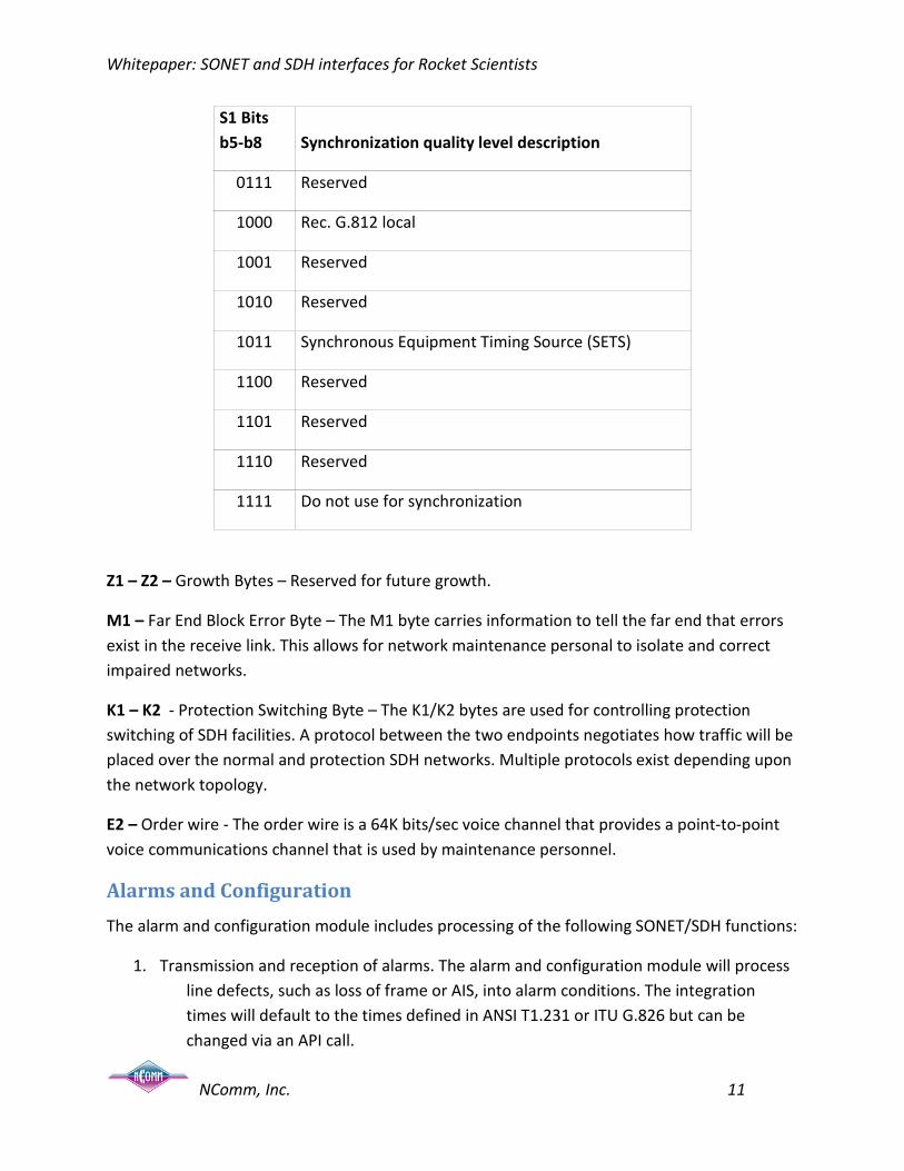
S1 – Synchronization Status Message – The S1 byte is used to carry synchronization trace information. The low order 4 bits (Bits 5-8) carry the message as shown in the following table.
S1 Bits b5-b8
Synchronization quality level description
0000 Quality unknown
0001 Reserved
0010 Rec. G.811
0011 Reserved
0100 Rec. G.812 transit
0101 Reserved
0110 Reserved
Whitepaper: SONET and SDH interfaces for Rocket Scientists
NComm, Inc. 11
S1 Bits b5-b8
Synchronization quality level description
0111 Reserved
1000 Rec. G.812 local
1001 Reserved
1010 Reserved
1011 Synchronous Equipment Timing Source (SETS)
1100 Reserved
1101 Reserved
1110 Reserved
1111 Do not use for synchronization
Z1 – Z2 – Growth Bytes – Reserved for future growth.
M1 – Far End Block Error Byte – The M1 byte carries information to tell the far end that errors exist in the receive link. This allows for network maintenance personal to isolate and correct impaired networks.
K1 – K2 - Protection Switching Byte – The K1/K2 bytes are used for controlling protection switching of SDH facilities. A protocol between the two endpoints negotiates how traffic will be placed over the normal and protection SDH networks. Multiple protocols exist depending upon the network topology.
E2 – Order wire - The order wire is a 64K bits/sec voice channel that provides a point-to-point voice communications channel that is used by maintenance personnel.
Alarms and Configuration
The alarm and configuration module includes processing of the following SONET/SDH functions:
1. Transmission and reception of alarms. The alarm and configuration module will process line defects, such as loss of frame or AIS, into alarm conditions. The integration times will default to the times defined in ANSI T1.231 or ITU G.826 but can be changed via an API call.

Whitepaper: SONET and SDH interfaces for Rocket Scientists
NComm, Inc. 12
2. Configuration. The alarm and configuration module will allow the application to set the various operating parameters of the different SONET/SDH signal levels.
3. User vs. Network Side. As with most telecommunications interfaces, the SONET/SDH protocol is not symmetrical. Either user side (also known as Customer Interface – CI) or network side (NI) can be selected.
Performance Monitoring
The performance monitoring module includes the following features:
1. Performance Monitoring – The performance monitoring records the performance parameters specified in ANSI T1.231 or ITU G.826 whichever is appropriate. The performance parameters are stored in 15-minute buckets for a total of 192 buckets (representing 48 hours of information).
2. Time-of-day-processing – T1.231 specifies that performance information be tracked according to the time of day starting at 12:00 midnight and proceeding every 15 minutes. However, there are reasons that the time of day may need to be changed – daylight savings time for example. The performance monitoring will manage the change of the time of day and maintain the correct information in the buckets per T1.231. ITU G.826 has similar properties.
3. Threshold crossing alerts – The performance monitoring module provides the ability for the application to set thresholds on the performance parameters. During processing, when the performance monitoring module determines that the threshold has been crossed, it will notify the application via a call back.
Japanese SDH
Most of the world can be accommodated by either standard SONET or SDH. The only important exception that we are aware of is Japan. The Japanese standards JT-G707 and JT-G783 are very similar to the standards, ITU-T G.707 and ITU-T G783. However, they are not identical and the differences must be implemented to insure standard compliance and interoperability. Japanese SDH makes some tweaks to standard SDH and adds the concept of the JHG or the Japanese Handling Group. The following goes into a little more detail of what these differences are.
STM-0: The STM-0 rate defined in JT-G707 is equivalent to the STS-1 rate defined by Bellcore.
There are two options for mapping the VC-11/TU-11 bytes.
1. STM-0 supports 28 VC-11/TU-11

Whitepaper: SONET and SDH interfaces for Rocket Scientists
NComm, Inc. 13
2. STM-1 support 3*STM-0 (i.e. 28*3 VC-11/TU-11).
There are three alarms that are maintained separately for each handling group:
LOS – loss of HG alignment
AIS – detection of AIS in the HG
RDI – presence of three consecutive 0s in the Sp/BAIS bit.
VT Group Structure: The Japanese Handling Group (JHG) implementation of SDH maps and demaps 1.544 Mbits/s using VC-11/TU-11 in byte synchronous mode only. For signaling information, it uses a handling group concept. This combines the signaling information for six DS0s into a handling group. There are four handling groups for each DS1 line. The figure below shows the details of how the individual time slots are grouped together. Only two of the four time slots are shown in the figure.
1 2 3 54 6 7 8 9 1110 12 13 14 15 1716 18 19 20 21 2322 24
DS
1Ti
me
Slo
t
HG
4
HG
1
HG
2
HG
3
Time Slot Grouping
In the JHG implementation, the byte following the V5-byte in the VT SPE is called the W-byte. In byte synchronous mode, signaling bits (S1, S2, S3, & S4) for each handling group get mapped into dedicated ST-bits. These bits are placed in the W-byte in the VT mapper frame as shown below.
P1 P0 ST1 ST2 ST3 ST4 F R

Whitepaper: SONET and SDH interfaces for Rocket Scientists
NComm, Inc. 14
W-Byte Contents
Handling Groups Each handling group consists of a framing bit (F), six signaling bits (As) and an alarm bit (Sp), which is also called Backward AIS (BAIS). The JHG implementation uses the ST frame format that consists of eight VT frames (1 ms). The signaling bits of the eight W-bytes from the ST frame format (ST1 – ST4) are shown below (See Figure 26). The F locations are arbitrary with respect to one another.
A22 A19F A12
Sp A23A1 A16
F SpA5 A20
A2 FA9 A24
A6 A3A13 Sp
A10 A7A17 F
A14 A11A21 A4
A18 A15Sp A8
S1/HG1 S2/HG2 S3/HG3 S4/HG4
W-Byte Signaling Bits
The F-bit is an ST framing bit, which toggles between 0 and 1 every ST multiframe. This framing bit might not be aligned between the handling groups.

Whitepaper: SONET and SDH interfaces for Rocket Scientists
NComm, Inc. 15
Automatic Protection Switching
There are four standards that define APS for SONET and SDH transport. The general set is T1.105 (there are a number of sub-documents). GR-253 addresses Linear APS while GR-1400 and GR-1230 specify Unidirectional Path Switched Ring (UPSR) and Bi-directional Line Switched Ring (BLSR), respectively. For SDH, G.841 defines Linear Protection Switching and Ring Protection Switching.
There are three models of Linear APS. They are 1 + 1, 1:1 and 1:n. Linear APS is used primarily in applications linked to the core network and by definition are point to point. All Linear APS solutions have the drawback of asymmetric delay. Additional buffering at the nodes is required to overcome this. Buffering raises the cost of the equipment
1 + 1 provides two fiber links. Each link carries identical traffic. The receivers at each end monitor the bit streams and choose the “best” one. 1 + 1 is the most expensive but also offers the fastest recovery often without any data loss. It is expensive because two receivers are required at each end point, twice as much fiber is needed, and no additional capacity is gained.
1:n including the special case of 1:1, as its name implies, provides one backup fiber for up to 14 primary fibers. The back-up fiber can carry low priority traffic when not used for back up. There is a time to detect and time to switch traffic from the primary to the back up, and some loss will be experienced. As the detect plus switching times must be kept to 60 mSec or less, conventional phone calls should not be dropped (The network is architected for calls to withstand up to 2.5 seconds of disruption). This method is much less expensive because one fiber provides coverage for multiple primary fibers.
Ring APS comes in two flavors. That is UPSR (Unidirectional Path Switched Ring) and BLSR (Bidirectional Line Switched Ring).
Of the Ring APS methods, UPSR is relatively simple. There are two, counter-rotating fiber links. Each fiber carries the identical traffic. Each “node” monitors both fibers and picks the “best” one based on several criteria. These criteria include bit error rate, AIS (Alarm Indication Signal) and a couple of others. Some of the positive aspects of UPSR include that the receiver makes all decisions with no interaction with either the local or remote transmitter, no communications channel is needed, and it provides virtually un-interrupted service. The down side includes the need for redundant transceivers as well as introducing asymmetric delay (More information can be found in GR-1400).
BLSR is a bit more complicated. This method uses the K1/K2 bytes as well as other local indications to raise a flag to switch. Once the flag is raised, an independent “controller” then communicates with the local back-up facility (through the back-up SONET/SDH transceiver) via the K1/K2 bytes that communicate to a far end transceiver to prepare for the transfer of the

Whitepaper: SONET and SDH interfaces for Rocket Scientists
NComm, Inc. 16
traffic from the failed facility to the back-up facility. Together the switch is synchronized and executed.
Once a switch is executed by any of the methods (linear or ring), its next action is dependent on whether it has been configured as revertive or non-revertive. If it is revertive, the traffic will be automatically switched back to the original facility once it is recognized as good. In non-revertive, the traffic will stay switched until it is manually switched back.
Usually, these switches will be configured as non-revertive. The reason that APS has been implemented in the first place is that the traffic being carried is very large and a service outage is very costly. It is not uncommon for a bad line to appear as fixed for short periods of time while the carrier is determining and fixing the line problems. Automatically switching back could create repeated switches further disrupting service. In 1:1 or 1+1 modes, non-revertive is the norm. After a switch is performed and the faulty facility is repaired, that facility becomes that back-up line.
All APS must meet certain performance thresholds to be standard complaint. The budget for detecting a failure and initiating a switchover must be within 10 mS. Completion of the switchover must be within 50 mS of the initiation. Thus, the maximum time from detection of the failure to complete restoral is 60 mS.
There are several different criteria for making the switching decision. These include:
• AIS (Alarm Indication Signal)
• LOP (Loss Of Pointer)
• Unequipped (indicated in the C2 byte)
• RDI (Remote Defect Indication)
• Bit Error Ratio (Severely Errored Seconds/Errored Seconds)
• Bi-directional or 1:n APS uses the K1 and K2 bytes to also pass information.
Where these various indications are used depends on the type of APS being implemented. Line level indicators are used for Linear Models and Line and Path level for Ring models. K1/K2 are used only when there is a sharing of the back-up facility or when communication with the far end is required for coordination. An examination of the relevant standards will provide the details for your implementation.

Whitepaper: SONET and SDH interfaces for Rocket Scientists
NComm, Inc. 17
Interoperability and NComm's TMS
While there are standards for SONET and SDH APS, interoperability is still an issue. There have been groups that have tried to remedy this situation but to date have not been successful. In discussions with carriers, this reality has forced them to use a single equipment provider within a network being protected. Carriers typically do not like to be tied to a single source and NComm expects this to change. One of the benefits of NComm's Trunk Management Software generally and the APS modules in particular is that their use goes a long way towards achieving interoperability.
Software Architecture
Products requiring SONET/SDH interfaces face the daunting task of providing many low-level functions so that the applications conform to the different SONET/SDH standards. Hardware implementations of OC-N systems may involve various and mixed devices that access different sub-levels of an OC or STS signal. The Trunk Management Software must supply a set of function calls that permit development of high-level application software independent of the hardware implementation. One way to do this is to use a polymorphic device driver mapping methodology. This methodology permits potentially many device drivers to appear as one virtual device to the upper level application software. This also maintains a commonality in general device driver development.
Standards Compliance
The table below lists the standards that were discussed and would need to be complied with. Please note there can be several versions of any given standard so the release date or version is included.
Standard number Title Release Date or Version
ANSI T1.105.01 Synchronous Optical Network (SONET) – Automatic Protection Switching
1998
ANSI T1.107 and ANSI T1.107a
for Telecommunications - Digital Hierarchy – Format Specifications
1995
ANSI T1.231 Layer 1 In-Service Digital Transmission Performance Monitoring
2003
ANSI T1.231.04 SONET - Layer 1 In-Service Digital Transmission Performance Monitoring
2003

Whitepaper: SONET and SDH interfaces for Rocket Scientists
NComm, Inc. 18
Standard number Title Release Date or Version
ITC JT-G707 Network node interface for the Synchronous Digital Hierarchy (SDH)
4th Edition April 1997
ITC JT-G783 Maintenance Signal and Protection Switching for the Synchronous Digital Hierarchy (SDH) Multiplexing Equipment
2nd Edition April 1998
ITU-T G.707 / Y.1322 Network node interface for the synchronous digital hierarchy (SDH)
12/2003 08/2004 Amend 1
ITU-T G.783 Characteristics of synchronous digital hierarchy (SDH) equipment functional blocks
02/2004
ITU-T G.784 Synchronous digital hierarchy (SDH) management 06/1999
ITU-T G.826 End-to-end performance parameters and objectives for international, constant bit-rate digital paths and connections
12/2002
ITU-T G.829 Error performance events for SDH multiplex and regenerator sections
12/2002
ITU-T G.832 Transport of SDH elements on PDH networks – Frame and multiplexing structures
10/1998 06/2004 Amend 1
Telcordia GR-253-CORE Synchronous Optical Network (SONET) Transport Systems: Common Generic Criteria
Issue 3 September 2000
Whitepaper: SONET and SDH interfaces for Rocket Scientists
NComm, Inc. 19
Glossary
The terminology found in this document is based on the definitions found in various standards and other ANSI documents. The most commonly used terms are noted below.
Alarm Indication Signal (AIS) A signal transmitted in lieu of the normal signal to maintain transmission continuity and to indicate to the receiving equipment that there is a transmission interruption located either at the equipment originating the AIS signal or upstream of that equipment.
Asynchronous Transfer Mode (ATM) A multiplexing/switching technique in which information is organized in fixed-length cells with each cell consisting of an identification header field and an information field; the transfer mode is asynchronous in the sense that the recurrence of cells depends on the required or instantaneous bit rate.
Blue Alarm An AIS signal.
Bursty Errored Seconds (BES) See Severely Errored Sections (SES).
Channel Associated Signal (CAS) A method of signaling that assigns signaling bits that correspond to their timeslot.
Channelized, Channel, Channel Timeslot A frame is said to be channelized if the payload timeslots are assigned in a fixed pattern to signal elements from more than one source, each operating at a slower digital rate. T1: the 192 payload bits represent 24, 8-bit channel time slots, making up 24 individual 64kbits/s (DS0) bit streams; each DS0 is referred to as a channel. The eight contiguous digit timeslots associated with a DS0 channel are referred to as a channel time slot. T3: Typically a T3 will consist of 7 T2 signals with each T2 containing 4 T1 interfaces. For E3, the payload is up to 4 E2s and each E2 can have 4 E1s.
Concatenated Synchronous Transport Signal level N (STS-Nc) A signal constructed by concatenating the envelope capacities of N STS-1s to carry an STS-Nc SPE that transports a super-rate signal. These STS-1s shall be transported as a single entity.
Cyclic Redundancy Check (CRC) A method of detecting the existence of errors in the transmission of a digital signal using polynomial division.
DS1 (Digital Signal 1, T1) A digital signal transmitted at the nominal rate of 1.544 Mbits/s.
E1 A digital signal transmitted at the nominal rate of 2.048 Mbits/sec
Errored Second (ES) A one second interval with an error. See AT&T standard TR 54016 (T1), ANSI standard T1.231 or ITU-T standard G.826 (E1/E3)

Whitepaper: SONET and SDH interfaces for Rocket Scientists
NComm, Inc. 20
Extended Super Frame (ESF) A DS1/T1 framing format of 24 frames. In this format, 2 Kbps are used for framing pattern sequence, 4 Kbps are used for the Facility Data Link, and the remaining 2 Kbps are used for CRC. A one second interval with an error. See TR 54016.
Frame T1: A set of 192 timeslots for the information payload, preceded by a one-digit timeslot containing the framing (F) bit, for a total of 193 timeslots. The payload is often DS0-channelized into 24 channel timeslots. E1: A set of 256 bits organized into 32 timeslots numbered 1 to 32. Timeslot 1 contains the framing pattern, CRC-4, Si bits, Sa Bits, and A bit. When CAS signaling is used, timeslot 17 is used to carry the signaling bits for each channel. T3: A set of 192 timeslots for the information payload, preceded by a one-digit timeslot containing the framing (F) bit, for a total of 193 timeslots. The payload is often DS0-channelized into 24 channel timeslots. E3: A set of 32 timeslots.
Framer Loopback An internal (within the framer) loopback that tests the path up to where framing is introduced. Used for diagnostics.
In-Band Using or involving the information digit timeslots of a frame; i.e., bit assignments of a frame exclusive of the framing bit.
Line In SONET/SDH, a transmission medium, together with the associated equipment, required to provide the means of transporting information between two consecutive Network Elements (NEs), one of which originates the signal and the other terminates it.
Line Coding Violation (LCV) The occurrence of either a Bipolar Violation or Excessive Zeros.
Line Loopback A loopback in which the signal returned toward the source of the loopback command consists of the full signal with (1) bit sequence integrity maintained, (2) no change in framing, and (3) no removal of bipolar violations.
Local Loopback An internal (within the framer) diagnostic loopback in which the signal returned towards the source is framed.
Loopback A state of a transmission facility in which the received signal is returned towards the sender.
Loss Of Frame (LOF) or Out Of Frame (OOF) A framing error occurred; for SONET/SDH the network element is unable to frame align on an incoming signal.
Loss Of Signal (LOS) When no pulses are detected of either positive or negative polarity.
Operations, Administration, and Maintenance (OAM) OA&M is a general term born out of the WAN telecommunications industry that applies to the configuration, control, and performance monitoring of WAN communications. When applied to Ethernet, the term OA&M is usually shortened to simply OAM.
Out Of Frame (OOF) A framing error occurred.

Whitepaper: SONET and SDH interfaces for Rocket Scientists
NComm, Inc. 21
Path In SONET/SDH, A logical connection between the point at which a standard frame format for the signal at the given rate is assembled and the point at which the standard frame format for the signal is disassembled.
Path Coding Violation (PCV) See Bipolar Violation.
Path Overhead (POH) Overhead assigned to and transported with the payload until the payload is demultiplexed. It is used for functions that are necessary to transport the payload.
Payload The information bits of a frame.
Section For SONET/SDH, the portion of a transmission facility, including terminating points, between a line terminating equipment (LTE) and Section Terminating Equipment (STE) OR between two Section Terminating Equipments.
Severely Errored Seconds (SES) This is a performance measure. See TR-54016 or G.826 for detailed information.
Super Frame (SF) A DS1/T1 framing format of 12 frames.
Synchronous Transport Signal Level 1 (STS-1) The basic logical building block signal with a rate of 51.840 Mbits/s.
Synchronous Transport Signal Level N (STS-N) This signal is obtained by byte interleaving N STS-1 signals together. The rate of the STS-N is N times 51.480 Mbits/s.
Yellow Alarm A Remote Alarm Indication signal. It is the indication from the far end equipment that it is having difficulties receiving the near end signal.

Whitepaper: SONET and SDH interfaces for Rocket Scientists
NComm, Inc. 22
About NCOMM
NComm, based in Hampstead, NH, provides turnkey embedded software solutions and hardware platforms that are used by equipment vendors to add Ethernet and WAN interfaces to their products. Developed by NComm’s team of engineering and business professionals, our products are designed using the experience obtained by decades of experience in communications software & hardware design and bringing complex products to market.
NComm Trunk Management Software is the Ethernet & WAN de facto standard, embedded by equipment vendors from 3COM to ADC to Sonus Networks and is the most widely used and tested software for Ethernet and WAN OAM. NComm delivers the underpinning, drop-in software technology necessary to build interoperable, standards-compliant WAN access devices including framer configuration, alarming & fault management, PMON, line testing, and signaling. NComm’s mission is to reduce their client’s time-to-market through turnkey Ethernet, T1, E1, T3, E3, SONET, SDH, APS, Primary Rate ISDN and Sync Status Message telecommunications source code
For more information, call us at (603) 329-5221, or visit www.ncomm.com

NComm, Inc 130 Route 111
Suite 201 Hampstead, NH 03841 Phone: 603-329-5221
Fax: 603-329-5388 Email: [email protected]