sony nex 5 service manual level 1
TRANSCRIPT
NEX-3A/3D/3K/5A/5D/5K/5CK_L2Sony Corporation
SERVICE MANUAL
Revision History
SERVICE NOTE (Check the following note before the service.)
Ver. Date History Contents S.M. Rev.issued
LEVEL 2
985279731.pdf
2010E29-1© 2010.5
Published by Sony Techno Create Corporation
Ver. 1.0 2010.05
INTERCHANGEABLE LENS DIGITAL CAMERAThe components identified by mark 0 or dotted line with mark 0 are critical for safety.Replace only with part number specified.
Les composants identifiés par une marque 0 sont critiques pour la sécurité.Ne les remplacer que par une pièce portant le numéro spécifié.
US ModelCanadian Model
AEP ModelUK Model
E ModelAustralian Model
Chinese ModelKorea Model
Japanese ModelTourist Model
1-1. PRECAUTION ON REPLACING THE SY-258 BOARD1-2. PRECAUTION ON REPLACING THE CABINET FRONT
—Official Release2010.051.0
9-852-797-31
NEX-3A/3D/3K/5A/5D/5K/5CKRMT-DSLR1
—
Photo: NEX-5/Black
[About the service of this model]NEX-3A/5A is a commodity that packed the Interchangeable Lens Digital Camera (NEX-3/5) and Interchangeable Lens (E 16mm F2.8).NEX-3D/5D is a commodity that packed the Interchangeable Lens Digital Camera (NEX-3/5) and Interchangeable Lens
(E 16mm F2.8 / E 18-55mm F3.5-5.6 OSS).NEX-3K/5K/5CK is a commodity that packed the Interchangeable Lens Digital Camera (NEX-3/5/5C) and Interchangeable Lens
(E 18-55mm F3.5-5.6 OSS).
Refer to each following service manual of the Interchangeable Lens kit, when you repair.• Interchangeable Lens SEL16F28 (E 16mm F2.8) Service Manual (9-852-798-1[]) SEL1855 (E 18-55mm F3.5-5.6 OSS) Service Manual (9-852-799-1[])
– ENGLISH –
– JAPANESE –1-1. SY-258基板交換時の注意1-2. 前キャビネット交換時の注意

NEX-3A/3D/3K/5A/5D/5K/5CK_L2– 2 –
SPECIFICATIONS
– ENGLISH – – JAPANESE –
概略仕様
本機や付属品の仕様および外観は、改良のため予告なく変更することがありますが、ご了承ください。
本体[形式]カメラタイプ:レンズ交換式デジタルカメラ使用レンズ:Eマウントレンズ
[撮像部]イメージセンサー:23.4× 15.6 mm (APS-Cサイズ)、CMOSイメージセンサー
総画素数:約14 600 000画素カメラ有効画素数:約14 200 000画素
[アンチダスト]システム:帯電防止コートおよび電磁振
動駆動によるアンチダスト機能[オートフォーカス]形式:コントラスト検出方式検出輝度範囲:EV0 ~ EV20(ISO 100相当、
F2.8レンズ使用時)
[露出制御]測光方式:イメージセンサーによる49分
割測光測光範囲:EV0 ~ EV20(ISO 100相当、
F2.8レンズ使用時)ISO感度(推奨露光指数):オート、
ISO200 ~ 12800露出補正:±2.0EV(1/3段ステップ)
[シャッター]形式:電子制御式縦走りフォーカルプ
レーンシャッターシャッタースピード範囲:1/4000 ~ 30秒、
バルブ(1/3段ステップ)フラッシュ同調速度:1/160秒
[記録メディア]
[液晶モニター]形式:7.5 cm(3.0型)TFT駆動
“メモリースティックPROデュオ”、SDカード
ドット数:921 600(640×3(RGB)×480)ドット
[入出力端子]USB端子:miniBHDMI端子:HDMIタイプCミニ端子
[電源]バッテリー:リチャージャブルバッテリー
パックNP-FW50
[その他]Exif Print:対応PRINT Image Matching III:対応外形寸法:
NEX-5:約110.8×58.8×38.2 mm(幅×高さ×奥行き、突起部を除く)NEX-3:約117.2×62.6×33.4 mm(幅×高さ×奥行き、突起部を除く)
本体質量:NEX-5:約287 g(バッテリー、“メモリースティックPROデュオ”を含む)
モリースティックPROデュオ”を含む)
約229 g(本体のみ)NEX-3:約297 g(バッテリー、“メ
約239 g(本体のみ)動作温度:0℃~40℃記録方式:
静止画記録方式:JPEG(DCFVer.2.0、Exif Ver.2.3、MPFBaseline)準拠、DPOF対応NEX-5:動画記録方式(AVCHD方式):AVCHD規格Ver.1.0準拠映像:MPEG-4 AVC/H.264音声:Dolby Digital 2chドルビーデジタルステレオクリエーター搭載・ドルビーラボラトリーズからの 実施権に基づき製造されています。動画記録方式(MP4方式):映像:MPEG-4 AVC/H.264音声:MPEG-4 AAC-LC 2ch
NEX-3:動画記録方式:MPEG-4 Visual
USB通信:Hi-Speed USB(USB2.0準拠)
フラッシュガイドナンバー:7(ISO100・m)充電時間:約4秒照射角:16mmレンズをカバー(レンズ
表記の焦点距離)調光補正:±2.0EV(1/3段ステップ)外形寸法:約35.9×23.8×42.7 mm(幅
×高さ×奥行き、突起部を除く)本体質量:約20.4 g
バッテリーチャージャーBC-VW1定格入力:AC100 V - 240 V、
50 Hz/60 Hz、4.2 W定格出力:DC 8.4 V、0.28 A動作温度:0℃~40℃保存温度:-20℃~+60℃最大外形寸法:約63×95×32 mm(幅
×高さ×奥行き)本体質量:約85 g
リチャージャブルバッテリーパックNP-FW50使用電池:リチウムイオン蓄電池最大電圧:DC 8.4 V公称電圧:DC 7.2V容量:公称容量 7.7 Wh(1 080 mAh)定格(最小)容量:7.3 Wh(1 020 mAh)最大外形寸法:約31.8×18.5×45 mm(幅×高さ×奥行き)
本体質量:約57 g
BC-VW1 Battery chargerInput rating: 100 V – 240 V AC,
50 Hz/60 Hz, 4.2 WOutput rating: 8.4 V DC, 0.28 AOperating temperature range: 0°C to
40°C (32° to 104°F)Storage temperature range: –20°C to
+60°C (–4°F to +140°F)Maximum dimensions: Approx. 63 ×
95 × 32 mm (2 1/2 × 3 3/4 × 1 5/16inches) (W/H/D)
Mass: Approx. 85 g (3 oz)
Rechargeable battery packNP-FW50Used battery: Lithium-ion batteryMaximum voltage: DC 8.4 VNominal voltage: DC 7.2 VMaximum charge voltage: DC 8.4 VMaximum charge current: 1.02 ACapacity: Typical 7.7 Wh (1 080 mAh)
Minimum 7.3 Wh (1 020 mAh)Maximum dimensions:
Approx. 31.8 × 18.5 × 45 mm(1 5/16 × 3/4 × 1 13/16 inches)(W/H/D)
Mass: Approx. 57 g (2.1 oz)
Design and specifications are subjectto change without notice.
Camera[System]Camera type: Interchangeable lens
digital cameraLens: E-mount lens
[Image sensor]Image sensor: 23.4 × 15.6 mm (APS-C
format) CMOS image sensorTotal pixel number of image sensor:
Approx. 14 600 000 pixelsEffective pixel number of camera:
Approx. 14 200 000 pixels
[Anti-dust]System: Charge protection coating on
Low-Pass Filter andelectromagnetic vibrationmechanism
[Auto focus system]System: Contrast detection systemSensitivity range: 0 EV to 20 EV (at
ISO 100 equivalent, with F2.8 lens)
[Exposure control]Metering method: 49-segment
metering by the image sensorMetering range: 0 EV to 20 EV (at ISO
100 equivalent, with F2.8 lens)ISO sensitivity (Recommended
exposure index): Auto, ISO 200 to12800
Exposure compensation: ±2.0 EV (1/3EV step)
[Shutter]Type: Electronically-controlled,
vertical-traverse, focal-plane typeSpeed range: 1/4000 second to 30
seconds, BULB, (1/3 EV step)Flash sync speed: 1/160 second
[Recording media]“Memory Stick PRO Duo” media,SD card
[LCD monitor]LCD panel: 7.5 cm (3.0 type) TFT
driveTotal number of dots: 921 600 (640 × 3
(RGB) × 480) dots
[Input/output terminals]USB: miniBHDMI: HDMI type C minijack
[Power]Used battery pack: Rechargeable
battery pack NP-FW50
[Others]Exif Print: CompatiblePRINT Image Matching III:
CompatibleDimensions:
NEX-5/5C:Approx. 110.8 × 58.8 × 38.2 mm(4 3/8 × 2 3/8 × 1 9/16 inches)(W/H/D, excluding protrusions)NEX-3/3C:Approx. 117.2 × 62.6 × 33.4 mm(4 5/8 × 2 1/2 × 1 3/8 inches)(W/H/D, excluding protrusions)
Mass:NEX-5/5C:Approx. 287 g (10.1 oz)(including battery and “MemoryStick PRO Duo” media)Approx. 229 g (8.1 oz)(camera only)NEX-3/3C:Approx. 297 g (10.5 oz)(including battery and “MemoryStick PRO Duo” media)Approx. 239 g (8.4 oz)(camera only)
Operating temperature: 0°C to 40°C(32°F to 104°F)
File format:Still image: JPEG (DCF Ver. 2.0,Exif Ver. 2.3, MPF Baseline)compliant, DPOF compatibleNEX-5/5C:
Movie (AVCHD format):AVCHD Ver. 1.0 compliantVideo: MPEG-4 AV C/H.264Audio: Dolby Digital 2ch,equipped with Dolby DigitalStereo Creator• Manufactured under license
from Dolby Laboratories.Movie (MP4 format):Video: MPEG-4 AV C/H.264Audio: MPEG-4 AAC-LC 2ch
NEX-3/3C:Movie: MPEG-4 Visual
USB communication: Hi-Speed USB(USB 2.0 compliant)
FlashFlash guide number: GN 7 (in meters at
ISO 100)Recycling time: Approx. 4 secondsFlash coverage: Covering 16 mm lens
(focal length that the lens indicates)Flash compensation: ±2.0 EV (1/3 EV
step)Dimensions:
Approx. 35.9 × 23.8 × 42.7 mm(1 7/16 × 15/16 × 1 11/16 inches)(W/H/D, excluding protrusions)
Mass: Approx. 20.4 g (0.8 oz)

NEX-3A/3D/3K/5A/5D/5K/5CK_L2– 3 –
Model information table
• Abbreviation AUS : Australian model CH : Chinese model CND : Canadian model J : Japanese model JE : Tourist model KR : Korea model
Model NEX-3A NEX-3D NEX-3K
Destination US, CND, AEP, UK, E, KR, J, JE AEP, UK, E, AUS, KR, J US, CND, AEP, UK, E, AUS,
KR, JColor system Auto (PAL/NTSC) Auto (PAL/NTSC) Auto (PAL/NTSC)
BT-060 flexible board × × ×
BT-063 flexible board ○ ○ ○
RL-101 flexible com-plete board × × ×
RL-103 flexible com-plete board ○ ○ ○
FP-1236 flexible board × × ×
FP-1246 flexible board ○ ○ ○
Remote sensor × × ×
Eye-Fi Setup ○ ○ ○
Movie file format MPEG4 MPEG4 MPEG4
Lens E16 mm E18 – 55 mm/E16 mm E18 – 55 mm
Model NEX-5A NEX-5D NEX-5K NEX-5CK
Destination AEP, UK, E, AUS
US, CND, E, KR, J
AEP, UK, E, AUS, JE
CND, E, KR, J
AEP, UK, E, AUS
US, CND, E, KR, J CH
Color system PAL NTSC PAL NTSC PAL NTSC PAL
BT-060 flexible board ○ ○ ○ ○ ○ ○ ○
BT-063 flexible board × × × × × × ×
RL-101 flexible com-plete board ○ ○ ○ ○ ○ ○ ○
RL-103 flexible com-plete board × × × × × × ×
FP-1236 flexible board ○ ○ ○ ○ ○ ○ ○
FP-1246 flexible board × × × × × × ×
Remote sensor ○ ○ ○ ○ ○ ○ ○
Eye-Fi Setup ○ ○ ○ ○ ○ ○ ×
Movie file format AVCHD/MPEG4
AVCHD/MPEG4
AVCHD/MPEG4
AVCHD/MPEG4
AVCHD/MPEG4
AVCHD/MPEG4
AVCHD/MPEG4
Lens E16 mm E16 mm E18 – 55 mm/E16 mm
E18 – 55 mm/E16 mm E18 – 55 mm E18 – 55 mm E18 – 55 mm

NEX-3A/3D/3K/5A/5D/5K/5CK_L2– 4 –
SAFETY-RELATED COMPONENT WARNING!!
COMPONENTS IDENTIFIED BY MARK 0 OR DOTTED LINE WITH MARK 0 ON THE SCHEMATIC DIAGRAMS AND IN THE PARTS LIST ARE CRITICAL TO SAFE OPERATION. REPLACE THESE COMPO-NENTS WITH SONY PARTS WHOSE PART NUMBERS APPEAR AS SHOWN IN THIS MANUAL OR IN SUPPLEMENTS PUBLISHED BY SONY.
ATTENTION AU COMPOSANT AYANT RAPPORT À LA SÉCURITÉ!
LES COMPOSANTS IDENTIFIÉS PAR UNE MARQUE 0 SUR LES DIAGRAMMES SCHÉMATIQUES ET LA LISTE DES PIÈCES SONT CRITIQUES POUR LA SÉCURITÉ DE FONCTIONNEMENT. NE REM-PLACER CES COMPOSANTS QUE PAR DES PIÈCES SONY DONT LES NUMÉROS SONT DONNÉS DANS CE MANUEL OU DANS LES SUPPLÉMENTS PUBLIÉS PAR SONY.
CautionDanger of explosion if battery is incorrectly replaced.Replace only with the same or equivalent type.Dispose of used batteries according to the instructions.
Caution電池の交換は,正しく行わないと破裂する恐れがあります。電池を交換する場合には必ず同じ型名の電池又は同等品と交換してください。使用済み電池は,取扱指示に従って処分してください。
CHEMICALS
Some chemicals used for servicing are highly volatile.Their evaporation caused by improper management affects your health and environment, and wastes resources.Manage the chemicals carefully as follows.
• Store chemicals sealed in a specific place to prevent from exposure to high temperature or direct sunlight.
• Avoid dividing chemicals into excessive numbers of small containers to reduce natural evaporation.
• Keep containers sealed to avoid natural evaporation when chemicals are not in use.
• Avoid using chemicals as much as possible. When using chemicals, divide only required amount to a small plate from the container and use up it.
EXTERIOR PARTS
Be careful to the following points for plastic parts used in this unit.
• Use a piece of cleaning paper or cleaning cloth for cleaning plastic parts. Avoid using chemicals.
Even if you have to use chemicals to clean heavy dirt, don’t use paint thinner, ketone, nor alcohol.
• Insert the specific screws vertically to the part when installing a plastic part.
Be careful not to tighten screws too much.
UNLEADED SOLDERThis unit uses unleaded solder. Boards requiring use of unleaded solder are printed with the lead free mark (LF) indicating the solder contains no lead.(Caution: Some printed circuit boards may not come printed with the
lead free mark due to their particular size.)
: LEAD FREE MARKBe careful to the following points to solder or unsolder.
• Set the soldering iron tip temperature to 350 °C approximately. If cannot control temperature, solder/unsolder at high temperature
for a short time. Caution: The printed pattern (copper foil) may peel away if the
heated tip is applied for too long, so be careful! Unleaded solder is more viscous (sticky, less prone to
flow) than ordinary solder so use caution not to let solder bridges occur such as on IC pins, etc.
• Be sure to control soldering iron tips used for unleaded solder and those for leaded solder so they are managed separately. Mixing un-leaded solder and leaded solder will cause detachment phenomenon.
SAFETY CHECK-OUT
After correcting the original service problem, perform the following safety checks before releasing the set to the customer.
1. Check the area of your repair for unsoldered or poorly-soldered connections. Check the entire board surface for solder splashes and bridges.
2. Check the interboard wiring to ensure that no wires are “pinched” or contact high-wattage resistors.
3. Look for unauthorized replacement parts, particularly transistors, that were installed during a previous repair. Point them out to the customer and recommend their replacement.
4. Look for parts which, through functioning, show obvious signs of deterioration. Point them out to the customer and recommend their replacement.
5. Check the B+ voltage to see it is at the values specified.6. Flexible Circuit Board Repairing • Keep the temperature of the soldering iron around 270 °C during
repairing. • Do not touch the soldering iron on the same conductor of the circuit
board (within 3 times). • Be careful not to apply force on the conductor when soldering or
unsoldering.
各種薬品の取り扱いについて
現在使用されている薬品の中には揮発性の高い薬品もあります。それらを不用意に取り扱い蒸発させてしまうと,環境や健康へ影響を与えたり,資源の無駄使いになります。各種薬品は,下記の点に注意して取り扱ってください。
・ 保管場所を定め,高温になったり直射日光の当たらない場所に密閉して保管してください。
・ 小分け(ハンドラップ等)する数は必要最小限に留め,容器による自然蒸発を防いでください。
・ 作業に使用しない時は,必ずキャップ等をして自然蒸発を防いでください。
・ 薬品を使用する回数を極力少なくし,使用する場合は使用する量だけ容器より出して受け皿に残さないようにしてください。
樹脂系部品の取り扱いについて
本機に使用されている樹脂系の部品は,下記の点に注意して取り扱ってください。
・ 清掃には薬品を使用せず,清掃紙や清掃布を使用してください。
やむを得ず汚れがひどくて薬品を使用する場合は,シンナー,ケトン,エーテルは使用しないでください。
・ 各部品の取り付けには指定されたねじを使用し,部品に対して垂直に取り付けてください。
また,ねじを締め付ける時は,無理な力を加えないでください。
1. 注意事項をお守りください。 サービスのとき特に注意を要する個所については,キャビネット,シャーシ,部品などにラベルや捺印で注意事項を表示しています。これらの注意書き及び取扱説明書等の注意事項を必ずお守りください。
2. 指定部品のご使用を セットの部品は難燃性や耐電圧など安全上の特性を持ったものとなっています。
従って交換部品は,使用されていたものと同じ特性の部品を使用してください。
特に回路図,部品表に0印で指定されている安全上重要な部品は必ず指定のものをご使用ください。
3. 部品の取付けや配線の引きまわしはもとどおりに 安全上,チューブやテープなどの絶縁材料を使用したり,プリント基板から浮かして取付けた部品があります。
また内部配線は引きまわしやクランパによって発熱部品や高圧部品に接近しないよう配慮されていますので,これらは必ずもとどおりにしてください。
4. サービス後は安全点検を サービスのために取外したネジ,部品,配線がもとどおりになっているか,またサービスした個所の周辺を劣化させてしまったところがないかなどを点検し,安全性が確保されていることを確認してください。
5. チップ部品交換時の注意 ・ 取り外した部品は再使用しないでください。 ・ タンタルコンデンサのマイナス側は熱に弱いため交換時
は注意してください。6. フレキシブルプリント基板の取扱いについて ・ こて先温度を270℃前後にして行なってください。 ・ 同一パターンに何度もコテ先を当てないでください。 (3回以内) ・ パターンに力が加わらないよう注意してください。
サービス,点検時には次のことにご注意ください。
無鉛半田について本機には無鉛半田が使用されています。無鉛半田を使用している基板には,無鉛(LeadFree)を意味するレッドフリーマークがプリントされています。(注意:基板サイズによっては,無鉛半田を使用していてもレッ
ドフリーマークがプリントされていないものがあります)
:レッドフリーマーク
無鉛半田は,下記の点に注意して使用してください。
・ 半田こてのこて先温度は約350℃に設定してください。 温度調節が無理な場合は,高温短時間で作業を行ってください。
注意:半田こてを長く当てすぎると,基板のパターン(銅箔)がはがれてしまうことがありますので,注意してください。また,従来の半田よりも粘性が強いため,IC端子などが半田ブリッジしないように注意してください。
・ 半田こてのこて先は,必ず無鉛半田用と有鉛半田用に分けて管理してください。
無鉛半田と有鉛半田が混在すると剥離現象が発生してしまいます。
– ENGLISH – – JAPANESE –

NEX-3A/3D/3K/5A/5D/5K/5CK_L21-1E
1. SERVICE NOTE
1-1. PRECAUTION ON REPLACING THE SY-258 BOARD
Destination DataWhen you replace to the repairing board, the written destination data of repairing board also might be changed to original setting.
USB Serial No.The set is shipped with a unique ID (USB Serial No.) written in it.This ID has not been written in a new board for service, and therefore it must be entered after the board replacement.
– ENGLISH – – JAPANESE –1-1. SY-258基板交換時の注意
仕向けデータ補修用基板と交換する時、補修用基板に書かれている仕向けデータは元の設定と違っている場合があります。
USBシリアルNo.セットは、1台毎に異なる固有のID(USB Serial No.)を書き込んだ後、出荷されています。新品の補修用基板には、このIDが書き込まれていないので,基板交換後にIDを入力する必要があります。
1-2. 前キャビネット交換時の注意
以下の手順は3箇所それぞれ行ってください。
注意: 前キャビネットの交換を行う前に、手順(1)から(3)にて交換前の寸法を測定してください。
(1) イメージャ Assy、IM調整ワッシャ (A, B, C)を取り外してください。
(2) 取り外したIM調整ワッシャの寸法(A)を測定してください。
A
A+BB
(3) IM調整ワッシャが取り付いていたビス穴端面からE-Mount端面までの寸法(B)を測定してください。(4) 前キャビネットを交換してください。(5) 前キャビネット交換後のIM調整ワッシャが取り付いていたビス穴端面からE-Mount端面までの寸法(B)を測定し、交換前の寸法
(B)と比較してください。 ・交換前の寸法(B)より交換後の寸法(B)が低かった場合 差分寸法分のIM調整ワッシャを追加し交換前の寸法(B)と同じ高さにしてください。 ・交換前の寸法(B)より交換後の寸法(B)が高かった場合 交換前の寸法(A+B) - 交換後の寸法(B)を行い、差分寸法分のIM調整ワッシャへ交換してください。(6) 組立完成後、試し撮りを行い周辺ボケが無いか確認してください。
1-2. PRECAUTION ON REPLACING THE CABINET FRONT
Perform the following procedures for each of the three washers.
Note: Measure the dimensions before replacement of the Cabinet Front according to procedures (1) to (3).
(1) Remove the Imager Block Assy and the IM Adjust Washers (A, B, C).
(2) Measure the dimensions (A) of the removed IM Adjust Washers.
A
A+BB
(3) Measure the distance (B) between the surface of the screw hole where the IM Adjust Washers were set and the surface of the E-Mount.(4) Replace Cabinet Front.(5) Measure the distance after replacement of the Cabinet Front (B) between the surface of the screw hole where the IM Adjust Washers were set and
the surface of the E-Mount, then compare it with the distance before replacement (B).• If the distance after replacement (B) is shorter than that before replacement (B)
Add IM Adjust Washer with the thickness equal to the difference of dimensions to make the distance (B) equal to that before replacement.• If the distance after replacement (B) is longer than that before replacement (B)
Replace to the IM Adjust Washer with the thickness equal to the difference of dimensions (distance before replacement (A+B) - distance after replacement (B)).(6) After assembly, take a test shot to check if there is any blur at circumference of the image.

NEX-3A/3D/3K/5A/5D/5K/5CK_L22-1
2. REPAIR PARTS LIST
Follow the disassembly in the given numerical order.(NEX-5A/5D/5K/5CK)
IDENTIFYING PARTS
Link ACCESSORIES
View Position
ASSEMBLY
• Abbreviation AUS : Australian model CH : Chinese model CND : Canadian model J : Japanese model JE : Tourist model KR : Korea model
(ENGLISH)
NOTE:• -XX,-Xmeanstandardizedparts,sotheymayhavesomedifferencesfromtheoriginalone.• Itemsmarked“*”arenotstockedsincetheyareseldomrequiredforroutineservice.Somedelayshouldbeanticipatedwhenorderingtheseitems.
• Themechanicalpartswithnoreferencenumberintheexplodedviewsarenotsupplied.• Duetostandardization,replacementsinthepartslistmaybedifferentfromthepartsspecifiedinthediagramsorthecomponentsusedontheset.
(JAPANESE)
【使用上の注意】 • -XX, -Xは標準化部品のため, セットに付いている部品と異なる場合があります。• *印の部品は常備在庫しておりません。• ここに記載されている部品は, 補修用部品であるため, 回路図及びセットに付いている部品と
異なる場合があります。
図面番号で部品を指定するときは基板名又はブロックを併せて指定してください。
お願い
• Color Indication of Appearance Parts Example: (SILVER) : Cabinet’s Color (Silver) : Parts Color
• 外装部品色表示 例: (SILVER) :セットの色を表す。 (Silver) :部品の色を表す。
The components identifiedbymark0 ordottedlinewithmark0arecriticalforsafety.Replaceonlywithpartnumberspecified.Lescomposantsidentifiésparunemarque0sontcritiquespourlasécurité.Nelesremplacerqueparunepièceportantlenumérospécifié.
0印の部品,または0印付の点線で囲まれた部品は,安全性を維持するために,重要な部品です。従って交換時は,必ず指定の部品を使用してください。
Whenindicatingpartsbyreferencenumber,pleaseincludetheboardname.
Bottom View
Top View
Back View
Right View
Left View
Front View
THE COMBINATION OF CABINET’S COLOR AND SCREW (NEX-5A/5D/5K/5CK)The screw pointed is different according to the cabinet's color.For the combination of cabinet's color and screw, please refer to Table 2-1.
Table 2-1Screw's
Ref.No.(PartsColor.) Cabinet'sColor
#201 (Silver), #202 (Silver) SILVER
#196 (Black), #200 (Black) BLACK
9�Tripod Screwqs�Cabinet Front Assy[Disassembly][Exploded View]• Cabinet Front Section-1• Cabinet Front Section-2
6�BT Holder Block Assy• BT-060 Flexible Board• FP-1236 Flexible Board• CN-439 Complete Board
qa�MB Driving Unit
0�Imager Block Assy[Disassembly][Exploded View]• IS-075 Flexible Board• IS-076 Flexible Board
5�Jack Cover Base Assy
1�Cabinet (Rear) Block Assy
4 SY-258 Complete Board
2 Control Switch Block
3�Main Frame Block Assy[Disassembly][Exploded View]• FP-1237 Flexible Complete Board
7�RL Button Block Assy
8�RL Block Assy• RL-101 Flexible Board

NEX-3A/3D/3K/5A/5D/5K/5CK_L22-2
– ENGLISH – – JAPANESE –
NOTE FOR REPAIR 修理時の注意• Makesurethattheflatcableandflexibleboardarenotcrackedorbentattheterminal.
Donotinsertthecableinsufficientlynorcrookedly.
• Whenremoveaconnector,donotpullatwireofconnector.It ispossiblethatawireissnapped.
• Wheninstallingaconnector,donotpressdownatwireofconnector. Itispossiblethatawireissnapped.
• Donotapplyexcessiveloadtothegildedflexibleboard.
• フラットケーブルおよびフレキシブル基板の端子面に欠け,折れ等がないことを確認する。
また,コネクタへの接続は,差し込み不足や斜め差しにならないように注意する。
• コネクタを取り外す時に,線材部(極細)を持って引っ張ると断線する恐れがありますので,絶対に線材部(極細)を持って引っ張らないでください。
• 線材部(極細)を押さえながらコネクタを差し込むと,線材部(極細)が断線する恐れがありますので,絶対に線材部(極細)には負担をかけないでください。
• 金メッキされているフレキシブル基板には,強い負担をかけないでください。
Cut and remove the part of giltwhich comes off at the point.(Be careful that somepieces of gilt may be left inside)
先端の剥がれたメッキ部はカットして除去してください。(メッキ破片がコネクタ内に残っている場合もあるので注意してください)

NEX-3A/3D/3K/5A/5D/5K/5CK_L22-3
2-1. EXPLODED VIEWS
2-1-1. OVERALL SECTION (NEX-5A/5D/5K/5CK)
ns:notsupplied
Ref. No. Part No. Description Ref. No. Part No. Description
DISASSEMBLY
1 X-2547-947-2 LID ASSY (BLACK), BT (BLACK) 1 X-2547-948-2 LID ASSY (SILVER), BT (SILVER)* 2 4-191-980-01 LABEL, MS 3 4-186-475-01 SPRING, BT LID OPEN (Note4) 4 X-2547-945-1 CABINET (REAR) ASSY (BRACK) (BLACK) (Note1, 2)
4 X-2547-946-1 CABINET (REAR) ASSY (SILVER) (SILVER) (Note1, 2) 5 4-186-478-01 GRIP (REAR), BLACK (BLACK) 5 4-186-478-11 GRIP (REAR), SILVER (SILVER) 6 4-186-479-01 SHEET, GRIP (REAR) ADHESIVE 7 4-186-476-01 SHAFT, BT LID
8 1-487-968-12 SWITCH BLOCK, CONTROL (BLACK) 8 1-487-968-22 SWITCH BLOCK, CONTROL (SILVER)* 9 4-186-841-01 LABEL, VCCI/ JAPAN RECYCLE MARK (J)
#155 3-080-204-31 SCREW, TAPPING, P2 #196 4-178-124-01 SPECIAL (M1.4 (D2.75)) (BLACK) (Note3) #200 4-178-124-11 SPECIAL (M1.4 (D2.75)) (BLACK) (Note3) #201 4-178-124-21 SPECIAL (M1.4 (D2.75)) (SILVER) (Note3) #202 4-178-124-31 SPECIAL (M1.4 (D2.75)) (SILVER) (Note3)
1 #200 / #202 X 4 → USB Cover Open (1-1) → #155 X 1 → Shoe Cover Open (1-2) →
#196 / #201 X 1 →LCD Panel Open
1. Remove to numerical order (1 to 2) in the left figure.
Note
Note1: Perform the followingprocedures to removeCabinet (Rear)Assy.
(1)OpenLCDattheangleshownbelow.
(2)RaisethelowerpartofCabinet(Rear)Assy,andslideit upward.
(3)RemoveCabinet(Rear)Assywhileturningitinthe directionindicatedbyarrows.
Note3: Refer to “THECOMBINATIONOFCABINET’SCOLORANDSCREW(NEX-5A/5D/5K/5CK)”onpage2-1about thecombinationofcabinet’scolorandscrew.
Right View Top ViewBottom ViewLeft View
#200#202 #200
#202
#155
#196#201
Note1: 後キャビネットAssyを取り外す場合,以下の手順で行ってください。
(1) LCDを下図の角度に開きます。
(2) 後キャビネットAssyの下部を手前へ起こし,後キャビ ネットAssyを上部へスライドします。
(3) 後キャビネットAssyを矢印の方向に回転させながら, 取り外します。
Note2: 組立時は“Assembly-1: Method of attachment of Cabinet (Rear) Assy”を参照してください。
Note2: Referto“Assembly-1:MethodofattachmentofCabinet(Rear)Assy”whenyouassemble.
Note3: キャビネット色とネジの組合わせについては,2 - 1 ページの“THE COMBINATION OF CABINET’S COLOR AND SCREW (NEX-5A/5D/5K/5CK)”を参照してください。
Screw
Note4: Referto“Assembly-6:MethodofattachmentofBTLidAssy”whenyouassemble.
Note4: 組立時は“Assembly-6: Method of attachment of BT Lid Assy”を参照してください。
1.7
6.0
#155: M1.7 X 6.0 (Tapping)(Black)3-080-204-31
#196: M1.4 X 2.0(Black)4-178-124-01
2.0
1.4
#200: M1.4 X 3.8(Black)4-178-124-11
3.8
1.4
#202: M1.4 X 3.8(Silver)4-178-124-31
3.8
1.4
#201: M1.4 X 2.0(Silver)4-178-124-21
2.0
1.4
LCD Section(See Page 2-4)
(Note3)#196#201
#155
#200#202(Note3)
5
3(Note4)
1
6
72(Claw)
2�8
1�4(Note1, 2)
ns
2
1-1
1-21(Claw)
#200#202(Note3)
9

NEX-3A/3D/3K/5A/5D/5K/5CK_L22-4
2-1-2. LCD SECTION (NEX-5A/5D/5K/5CK)
Ref. No. Part No. Description Ref. No. Part No. Description
DISASSEMBLY
51 4-186-569-01 INSULATING SHEET, LC FLEXIBLE (Note5, 6, 7) 52 X-2547-951-1 CABINET (REAR) ASSY, LC* 53 1-471-549-11 MAGNET (ND7.9X2.9X1.2) 54 4-186-568-01 INSULATING SHEET, LC CONNECTOR (Note6)* 55 4-186-563-01 RETAINER, LC FLEXIBLE
56 A-1773-793-A FP-1237 FLEXIBLE BOARD, COMPLETE* 57 4-186-555-01 LIGHT (LC), GUIDE, 58 4-186-572-02 INSULATING SHEET A (SY) (Note3)
* 59 X-2547-950-1 PIN ASSY, S LOCK* 60 4-186-566-01 BASE (L), STRAP (BLACK)
* 60 4-186-566-11 BASE (L), STRAP (SILVER)
#27 2-662-396-11 SCREW (M1.4), NEW, TRUSTAR, P2 #187 3-234-449-05 SCREW (M1.4) #196 4-178-124-01 SPECIAL (M1.4 (D2.75)) (BLACK) (Note4) #201 4-178-124-21 SPECIAL (M1.4 (D2.75)) (SILVER) (Note4)
3 #187 X 2 → #196 / #201 X 2 → LC Cabinet (Rear) Assy (3-1) → #187 X 2 → LC Flexible Retainer (3-2) → Release LCD Flexible Board (3-3) → Peel off LC Flexible Insulating Sheet (3-4) → #27 X 5 → Strap Base (L) (3-5) → S Lock Pin Assy (3-6)
1. Remove to numerical order (3) in the left figure.
Note
Note4: Refer to “THECOMBINATIONOFCABINET’SCOLORANDSCREW(NEX-5A/5D/5K/5CK)”onpage2-1about thecombinationofcabinet’scolorandscrew.
Note1: To removeFrameAssy, firstly removeLCDFlexibleBoardandLCFlexibleInsulatingSheet,thenunfixFP-1237FlexibleCompleteBoard.
Note2: Refer to “Assembly-2:Temporally secureFP-1237FlexibleCompleteBoard”whenyouassemble.
Note1: フレームASSYを取り外す場合,事前にLCDフレキシブルボード,LCフレキ絶縁シートを外し,FP-1237フレキシブルボードが固定されていない状態で作業を行ってください。
Note2: 組立時は“Assembly-2: Temporally secure FP-1237 Flexible Complete Board”を参照してください。
Note3: Refer to “Assembly-3: InsulatingSheetA (SY) puttingposition”whenyouassemble.
Note3: 組立時は“Assembly-3: Insulating Sheet A (SY) putting posi-tion”を参照してください。
Note4: キャビネット色とネジの組合わせについては,2 - 1 ページの“THE COMBINATION OF CABINET’S COLOR AND SCREW (NEX-5A/5D/5K/5CK)”を参照してください。
Note5: Refer to “Assembly-4: LCFlexible InsulatingSheet puttingposition”whenyouassemble.
Note5: 組立時は“Assembly-4: LC Flexible Insulating Sheet putting position”を参照してください。
Note6: Refer to “Assembly-5: LCConnector InsulatingSheet,LCFlexible InsulatingSheet puttingposition”when youassemble.
Note6: 組立時は“Assembly-5: LC Connector Insulating Sheet, LC Flex-ible Insulating Sheet putting position”を参照してください。
Screw
Note7: Refer to “Assembly-9: LCFlexible InsulatingSheet puttingposition”whenyouassemble.
Note7: 組立時は“Assembly-9: LC Flexible Insulating Sheet putting position”を参照してください。
Top View
#27
Bottom View
#196#201
#27
#187
LCD Back
3�Main Frame Section(See Page 2-10)(Note1, 2)
Main Board Section(See Page 2-5)
#196#201(Note4)
#27
#27
523-1
58(Note3)
57
3-659
3-560
513-4(Note5)
53#187
#187
3-3
56
54(Note6)
51(Note6)
51(Note7)
#27
553-2
SY-258
#27:M1.4 X 2.0(Black)2-662-396-11
2.0
1.4
1.4
1.4
#187: M1.4 X 1.4(Silver)3-234-449-05
#196: M1.4 X 2.0(Black)4-178-124-01
2.0
1.4
#201: M1.4 X 2.0(Silver)4-178-124-21
2.0
1.4
NEX-3A/3D/3K/5A/5D/5K/5CK_L22-5
Ref. No. Part No. Description Ref. No. Part No. Description
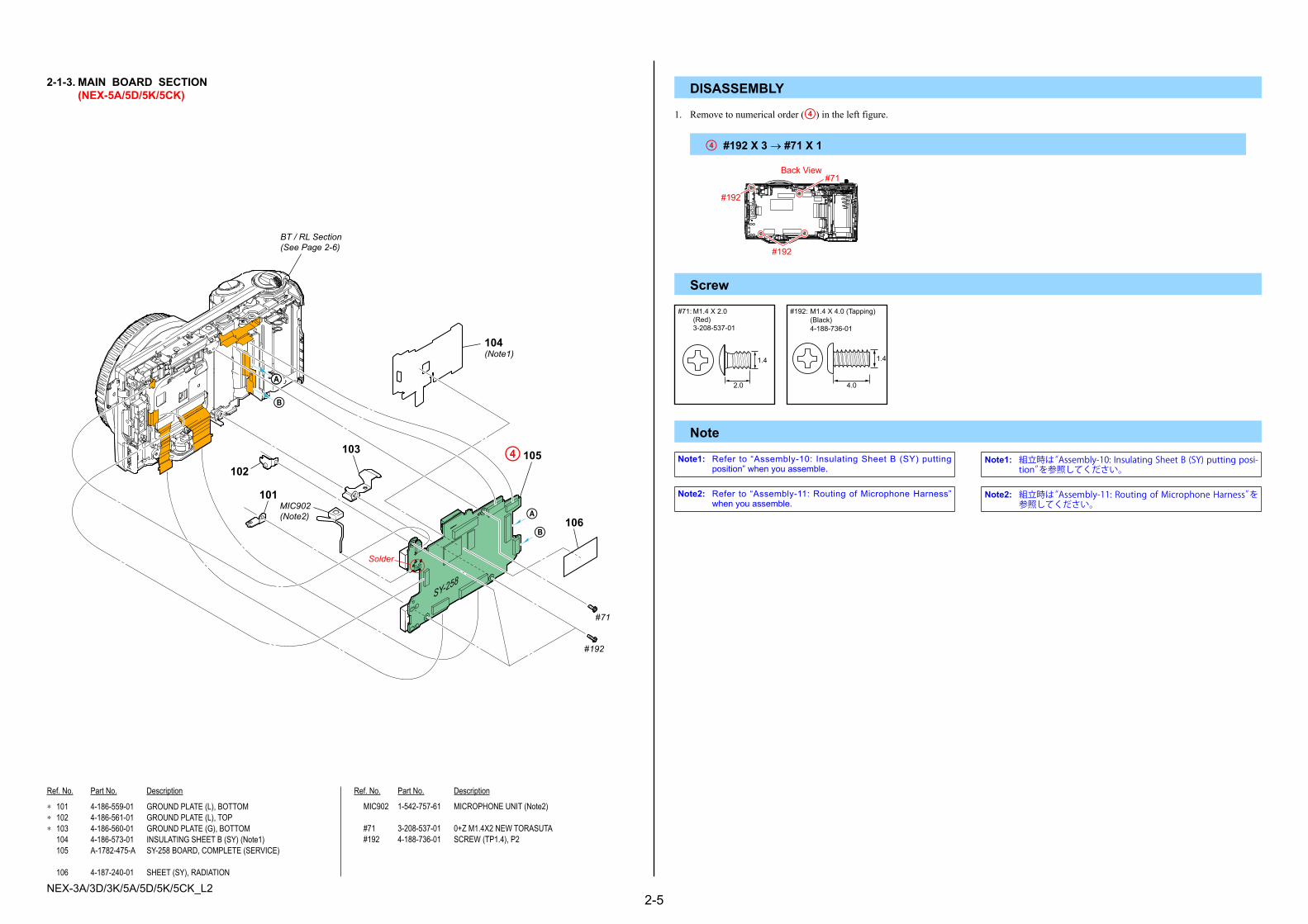
2-1-3. MAIN BOARD SECTION (NEX-5A/5D/5K/5CK) DISASSEMBLY
* 101 4-186-559-01 GROUND PLATE (L), BOTTOM* 102 4-186-561-01 GROUND PLATE (L), TOP* 103 4-186-560-01 GROUND PLATE (G), BOTTOM 104 4-186-573-01 INSULATING SHEET B (SY) (Note1) 105 A-1782-475-A SY-258 BOARD, COMPLETE (SERVICE)
106 4-187-240-01 SHEET (SY), RADIATION
MIC902 1-542-757-61 MICROPHONE UNIT (Note2)
#71 3-208-537-01 0+Z M1.4X2 NEW TORASUTA #192 4-188-736-01 SCREW (TP1.4), P2
1. Remove to numerical order (4) in the left figure.
4 #192 X 3 → #71 X 1
Note
Screw
Note1: Refer to “Assembly-10: InsulatingSheetB (SY) puttingposition”whenyouassemble.
Note1: 組立時は“Assembly-10: Insulating Sheet B (SY) putting posi-tion”を参照してください。
Note2: Refer to “Assembly-11:RoutingofMicrophoneHarness”whenyouassemble.
Note2: 組立時は“Assembly-11: Routing of Microphone Harness”を参照してください。
B
A
AA
Solder
#71
#192
104(Note1)
106
101
103
102
BT / RL Section(See Page 2-6)
MIC902(Note2)
4�105
B
SY-258
#192
Back View
#192
#71
#71:M1.4 X 2.0(Red)3-208-537-01
2.0
1.4
#192: M1.4 X 4.0 (Tapping)(Black)4-188-736-01
4.0
1.4

NEX-3A/3D/3K/5A/5D/5K/5CK_L22-6
Ref. No. Part No. Description Ref. No. Part No. Description
DISASSEMBLY
151 4-186-554-01 COVER, HDMI (BLACK) 151 4-186-554-11 COVER, HDMI (SILVER) 152 4-186-553-01 COVER, USB (BLACK) 152 4-186-553-11 COVER, USB (SILVER) 153 4-186-557-01 COVER, SHOE (BLACK)
153 4-186-557-11 COVER, SHOE (SILVER) 154 4-186-551-02 BASE, JACK COVER (BLACK) (Note6) 154 4-186-551-12 BASE, JACK COVER (SILVER) (Note6)* 155 4-186-446-01 LIGHT (MS), GUIDE,* 156 4-186-444-01 BASE, BT LID
157 A-1782-438-A RL BLOCK ASSY (SERVICE) (Note5)* 158 4-186-473-01 HOLDER, SP* 159 4-186-556-01 SCREW, TRIPOD 160 A-1782-432-A CABINET FRONT BLOCK ASSY (SERVICE) (BLACK)
(including CP001 (CMOS imager) and IS-077 complete board) (Note7, 9) 160 A-1782-433-A CABINET FRONT BLOCK ASSY (SERVICE) (SILVER)
(including CP001 (CMOS imager) and IS-077 complete board) (Note7, 9)
161 A-1774-556-A BUTTON BLOCK ASSY, RL
162 1-880-965-11 BT-060 FLEXIBLE BOARD 163 X-2547-936-1 BT FRAME ASSY (Note2)* 164 4-186-448-01 GASKET (MS) (Note1) 165 A-1773-791-A CN-439 BOARD, COMPLETE
166 4-186-449-01 SHEET (CN FPC) 167 1-880-967-11 FP-1236 FLEXIBLE BOARD* 168 4-186-447-01 INSULATING SHEET (MS) 169 4-186-568-01 INSULATING SHEET, LC CONNECTOR (Note10)
0 BT900 1-756-813-11 LITHIUM RECHARGEABLE BATTERY (Note4)0 BT901 1-780-858-11 TERMINAL BOARD BATTERY MIC901 1-542-757-61 MICROPHONE UNIT (Note3)
#27 2-662-396-11 SCREW (M1.4), NEW, TRUSTAR, P2 #71 3-208-537-01 0+Z M1.4X2 NEW TORASUTA #191 4-188-735-01 SCREW (M1.7) #192 4-188-736-01 SCREW (TP1.4), P2 #200 4-178-124-11 SPECIAL (M1.4 (D2.75)) (BLACK) (Note8)
#202 4-178-124-31 SPECIAL (M1.4 (D2.75)) (SILVER) (Note8)
1. Remove to numerical order (5 to 9) in the left figure.
6 #191 X 2
Note
2-1-4. BT / RL SECTION (NEX-5A/5D/5K/5CK)
#191
Back View
Screw
7 #192 X 1
#192
Bottom View
8 #27 X 1 → #191 X 1Back View
#27 #191
9 #200 / #202 X 1
Note1: Refer to “Assembly-12: InsertingGasket (MS) (NEX-5A/5D/5K/5CK)”whenyouassemble.
Note1: 組立時は“Assembly-12: Inserting Gasket (MS) (NEX-5A/5D/5K/5CK)”を参照してください。
Note2: Refer to “Assembly-13:AssembleBTHolderBlockAssy(NEX-5A/5D/5K/5CK)”whenyouassemble.
Note2: 組立時は“Assembly-13: Assemble BT Holder Block Assy (NEX-5A/5D/5K/5CK)”を参照してください。
Note3: Refer to “Assembly-14:RoutingofMicrophoneHarness(NEX-5A/5D/5K/5CK)”whenyouassemble.
Note3: 組立時は“Assembly-14: Routing of Microphone Harness (NEX-5A/5D/5K/5CK)”を参照してください。
Note4: Referto“Assembly-15:LithiumRechargeableBatteryputtingposition”whenyouassemble.
Note4: 組立時は“Assembly-15: Lithium Rechargeable Battery putting position”を参照してください。
Note5: Referto“Assembly-16:NotewhenassemblingRLBlockAssy(NEX-5A/5D/5K/5CK)”whenyouassemble.
Note5: 組立時は“Assembly-16: Note when assembling RL Block Assy (NEX-5A/5D/5K/5CK)”を参照してください。
Note6: Refer to “Assembly-19:NoteonAlignment of theFlexibleBoardwhenassemblingJackCoverBase
(NEX-5A/5D/5K/5CK)”whenyouassemble.
Note6: 組立時は“Assembly-19: Note on Alignment of the Flexible Board when assembling Jack Cover Base (NEX-5A/5D/5K/5CK)”を参照してください。
Note7:Precautions for Replacement of Cabinet Front Block Assy (Service)AsCabinet FrontBlockAssy (Service)may be damagedby staticelectricityfromitsstructure,handleitcarefullylikefortheMOSIC.Inaddition,ensurethatthereceiverisnotcoveredwithdustsnorexposedtostronglight.
Solder
Solder
Imager Block Section(See Page 2-7)(including CP001 (CMOS imager) and IS-077 complete board)160 (Note7, 9)
7�161
162
6�163 (Note2)
164 (Note1)
165166
#71#191
168167
#200#202(Note8)
#27
#192
#191
MIC901 (Note3)BT900 (Note4)
BT901
158
8�157(Note5) 156
155153
5�154 (Note6)
152
151
9�159
CN-439
169(Note10)
: BT900 (LITHIUM RECHARGEABLE BATTERY)Board on the mount position.(See page Level3 6-35)
Bottom View
#200#202
Note8: Refer to “THECOMBINATIONOFCABINET’SCOLORANDSCREW(NEX-5A/5D/5K/5CK)”onpage2-1about thecombinationofcabinet’scolorandscrew.
Note8: キャビネット色とネジの組合わせについては,2 - 1 ページの“THE COMBINATION OF CABINET’S COLOR AND SCREW (NEX-5A/5D/5K/5CK)”を参照してください。
#27: M1.4 X 2.0(Black)2-662-396-11
2.0
1.4
(Red)3-208-537-01
2.0
1.4
#191: M1.7 X 3.5 (Tapping)(Black)4-188-735-01
3.5
1.7
#192: M1.4 X 4.0 (Tapping)(Black)4-188-736-01
4.0
1.4
#200: M1.4 X 3.8(Black)4-178-124-11
3.8
1.4
#71: M1.4 X 2.0 #202: M1.4 X 3.8(Silver)4-178-124-31
3.8
1.4
Note7: 前キャビネットAssy (サービス)交換時の注意
前キャビネットAssy (サービス)は構造上,静電気により破壊される恐れがあるため,MOS ICと同様に注意して取り扱ってください。また,受光部にはゴミの付着,および強い光がはいることのないように注意してください。
Note9: Refer to “PRECAUTIONONREPLACINGTHECABINETFRONT”onpage1-1whenreplacingCabinetFrontBlockAssy(Service).
Note9: 前キャビネットAssy (サービス)を交換する場合,1 - 1 ページの“PRECAUTION ON REPLACING THE CABINET FRONT”を参照してください。
Note10:Refer to “Assembly-33: LCConnector InsulatingSheetputtingposition”whenyouassemble.
Note10: 組立時は“Assembly-33: LC Connector Insulating Sheet put-ting position”を参照してください。
CautionDangerofexplosionoccursifbatteryisincorrectlyreplaced.Replaceonlywiththesameorequivalenttype. Disposeofusedbatteriesaccordingtotheinstructions.
Caution電池の交換は,正しく行わないと破裂する恐れがあります。電池を交換する場合には必ず同じ型名の電池又は同等品と交換してください。使用済み電池は,取扱指示に従って処分してください。

NEX-3A/3D/3K/5A/5D/5K/5CK_L22-7
Ref. No. Part No. Description Ref. No. Part No. Description
2-1-5. IMAGER BLOCK SECTION (NEX-5A/5D/5K/5CK) DISASSEMBLY
0 201 A-1773-803-A MB CHARGE UNIT0 202 1-487-619-11 SHUTTER UNIT (H094)* 203 Selection Parts IM WASHER (C), ADJUST (Note1, 2)* 204 Selection Parts IM WASHER (B), ADJUST (Note1, 2)* 205 Selection Parts IM WASHER (A), ADJUST (Note1, 2)
206 4-185-968-02 MB TAPE, MASK SHEET (Note3) 207 4-185-966-01 MB SHEET, MASK (Note3)
#27 2-662-396-11 SCREW (M1.4), NEW, TRUSTAR, P2 #191 4-188-735-01 SCREW (M1.7) #197 4-185-990-01 MB SCREW, CHARGE UNIT FIXED
1. Remove to numerical order (0 to qs) in the left figure.
0 #191 X 3
Note
qa #27 X 1 → #191 X 1
Screw
Back View
#191
Back View
#191
#27
Note2: Refer to “Assembly-23: IMAdjustWasher (A,B,C) puttingposition”whenyouassemble.
Note2: 組立時は“Assembly-23: IM Adjust Washer (A, B, C) putting position”を参照してください。
Note3: Refer to “Assembly-24:Methodof attachment ofMBMaskSheet”whenyouassemble.
Note3: 組立時は“Assembly-24: Method of attachment of MB Mask Sheet”を参照してください。
206 (Note3)qs�Cabinet Front Section-1
(See Page 2-8)
Claw
Claw
#197
202
qa�201 #191
0�Imager Unit Section(See Page 2-11) #191
203(Note1, 2)
204 (Note1, 2)
205 (Note1, 2)
#27
207 (Note3)
#27:M1.4 X 2.0(Black)2-662-396-11
2.0
1.4
#191: M1.7 X 3.5 (Tapping)(Black)4-188-735-01
3.5
1.7
#197: M1.6 X 4.5 (Tapping)(Silver)4-185-990-01
4.5
1.6
Note1: Thetypeofthesepartsshouldbeselectedwhenperformingadjustments.
Referto"2-3.SELECTIONPARTS"onpage2-23.
Note1: これらの部品は調整によって種類を選択する必要があります。 2 - 23ページの“2-3. SELECTION PARTS”を参照してください。

NEX-3A/3D/3K/5A/5D/5K/5CK_L22-8
Ref. No. Part No. Description Ref. No. Part No. Description
2-1-6. CABINET FRONT SECTION - 1 (NEX-5A/5D/5K/5CK)
* 251 4-186-540-01 SHEET (FRONT), BT SLIDER (Note1)* 252 4-186-541-01 SHEET (HORIZONTAL), BT SLIDER (Note2)* 253 4-186-523-01 WINDOW (AF)* 254 4-186-525-01 BASE (FRONT), PW KNOB* 255 4-186-527-01 SHEET, PW RING ADHESIVE
* 256 4-186-528-01 RING, PW ORNAMENTAL (BLACK)* 256 4-186-528-11 RING, PW ORNAMENTAL (SILVER)* 257 4-186-530-01 KNOB, PW (BLACK)
* 257 4-186-530-11 KNOB, PW (SILVER)* 258 4-186-526-01 BASE (REAR), PW KNOB
* 259 4-186-537-01 SPRING, PW KNOB* 260 4-186-524-01 RETAINER, PW KNOB* 261 4-196-544-01 TAPE (AS (210)) (Note3)
#155 3-080-204-31 SCREW, TAPPING, P2
Note
Screw
Note1: Refer to “Assembly-25:BTSliderSheet (front) puttingposition(NEX-5A/5D/5K/5CK)”whenyouassemble.
Note1: 組立時は“Assembly-25: BT Slider Sheet (front) putting position (NEX-5A/5D/5K/5CK)”を参照してください。
Note2: Refer to “Assembly-26:BTSliderSheet (horizontal) puttingposition(NEX-5A/5D/5K/5CK)”whenyouassemble.
Note2: 組立時は“Assembly-26: BT Slider Sheet (horizontal) putting position (NEX-5A/5D/5K/5CK)”を参照してください。
#155
257
256
255
254253
258
252(Note2)
251(Note1)
259
260
Cabinet Front Section-2(See Page 2-9)
261(Note3)
1.7
6.0
#155: M1.7 X 6.0 (Tapping)(Black)3-080-204-31
Note3: Referto“Assembly-34:TapeAS(210)puttingposition(NEX-5A/5D/5K/5CK)”whenyouassemble.
Note3: 組立時は“Assembly-34: Tape AS (210) putting position (NEX-5A/5D/5K/5CK)”を参照してください。

NEX-3A/3D/3K/5A/5D/5K/5CK_L22-9
Ref. No. Part No. Description Ref. No. Part No. Description
301 4-185-964-03 MB N PLATE (A)* 302 4-185-962-01 MB N PLATE (B)* 303 4-185-963-01 MB N PLATE SP (Note1)* 304 4-186-539-01 RING, ORNAMENTAL* 305 4-186-534-01 BUTTON, L LOCK (BLACK)
* 305 4-186-534-11 BUTTON, L LOCK (SILVER)* 306 X-2547-937-1 PIN ASSY, L LOCK* 307 4-186-538-01 SPRING, LENS LOCK* 308 4-186-536-01 HOLDER, L LOCK 309 4-186-521-01 GRIP (BLACK)
309 4-186-521-11 GRIP (SILVER)* 310 4-186-519-01 WINDOW (IR) 311 4-186-542-01 SHEET, GRIP ADHESIVE 312 4-186-517-01 CABINET (FRONT) (BLACK) (Note3)
312 4-186-517-11 CABINET (FRONT) (SILVER) (Note3)
* 313 4-186-532-01 COVER, ORNAMENTAL RING (BLACK)* 313 4-186-532-11 COVER, ORNAMENTAL RING (SILVER)* 314 X-2547-938-1 PLATE ASSY, SHOE NUT 315 4-186-543-01 PLATE, LOGO (BLACK) 315 4-186-543-11 PLATE, LOGO (SILVER)
316 A-1773-802-A MB CONTACT UNIT, N (Note2, 4)
#23 3-080-204-11 SCREW, TAPPING, P2 #27 2-662-396-11 SCREW (M1.4), NEW, TRUSTAR, P2 #191 4-188-735-01 SCREW (M1.7) #195 3-197-324-01 M1.7X2.5X3GF (D4X0.5) #198 4-186-545-01 M1.7X4 SPIN
Note
2-1-7. CABINET FRONT SECTION - 2 (NEX-5A/5D/5K/5CK)
ns:notsupplied
Screw
Note1: Refer to “Assembly-27:Apply greaseonMBNPlateSP”whenyouassemble.
Note1: 組立時は“Assembly-27: Apply grease on MB N Plate SP”を参照してください。
Note2: Refer to “Assembly-28:MBNContactUnitholdingposition”whenyouassemble.
Note2: 組立時は“Assembly-28: MB N Contact Unit holding position”を参照してください。
303(Note1)
#198
ns
#195
#191
#27#23
302
304
301
307306
308
305
315
309
310
311 312 (Note3)
313
314
316(Note2, 4)
#23:M1.7 X 4.0 (Tapping)(Black)3-080-204-11
4.0
1.7
#27:M1.4 X 2.0(Black)2-662-396-11
2.0
1.4
#191: M1.7 X 3.5 (Tapping)(Black)4-188-735-01
3.5
1.7
2.5
1.7
#195: M1.7 X 2.5(Silver)3-197-324-01
4.0
1.7
#198: M1.7 X 4.0(Silver)4-186-545-01
Note3: Refer to “PRECAUTIONONREPLACINGTHECABINETFRONT”onpage1-1whenreplacingCabinet(Front).
Note3: 前キャビネットを交換する場合,1 - 1 ページの“PRECAUTION ON REPLACING THE CABINET FRONT”を参照してください。
Note4: Refer to “PRECAUTIONONREPLACINGTHECABINETFRONT”onpage1-1whenreplacingMBNContactUnit.
Note4: MB N 接点ユニットを交換する場合,1 - 1 ページの “PRECAUTION ON REPLACING THE CABINET FRONT”を参照
してください。

NEX-3A/3D/3K/5A/5D/5K/5CK_L22-10
Ref. No. Part No. Description Ref. No. Part No. Description
* 351 4-186-425-01 BRACKET (L), STRAP* 352 4-195-258-01 SHAFT, CUSHION (MF) (Note1) 353 4-186-571-01 SHEET, LC LIGHT INTERCEPTION0 354 A-1774-560-A PANEL BLOCK ASSY (BLACK)0 354 A-1774-561-A PANEL BLOCK ASSY (SILVER)
* 355 4-186-424-01 BRACKET (G), STRAP* 356 4-186-565-01 BASE (G), STRAP (BLACK)* 356 4-186-565-11 BASE (G), STRAP (SILVER) 357 4-186-438-01 PLATE, BT LOCK
358 4-186-437-01 CLAW, BT LOCK
359 X-2547-935-1 FRAME ASSY
#79 2-587-151-11 SCREW (M1.4), NEW TRUSTAR.P2 #187 3-234-449-05 SCREW (M1.4) #192 4-188-736-01 SCREW (TP1.4), P2 #196 4-178-124-01 SPECIAL (M1.4 (D2.75)) (BLACK) (Note2) #201 4-178-124-21 SPECIAL (M1.4 (D2.75)) (SILVER) (Note2)
Note
Note1: Refer to “Assembly-8:ShaftCushion (MF)puttingposition”whenyouassemble.
Note1: 組立時は“Assembly-8: Shaft Cushion (MF) putting position”を参照してください。
Screw2-1-8. MAIN FRAME SECTION (NEX-5A/5D/5K/5CK)
ns:notsupplied
#196#201(Note2)
#79
#187
#192
#79
354
356
355
357
358
353
352 (Note1)
351
ns
359
Note2: Refer to “THECOMBINATIONOFCABINET’SCOLORANDSCREW(NEX-5A/5D/5K/5CK)”onpage2-1about thecombinationofcabinet’scolorandscrew.
Note2: キャビネット色とネジの組合わせについては,2 - 1 ページの“THE COMBINATION OF CABINET’S COLOR AND SCREW (NEX-5A/5D/5K/5CK)”を参照してください。
2.0
1.4
#79:M1.4X 2.0(Silver)2-587-151-11
1.4
1.4
#187: M1.4 X 1.4(Silver)3-234-449-05
#196: M1.4 X 2.0(Black)4-178-124-01
2.0
1.4
#201: M1.4 X 2.0(Silver)4-178-124-21
2.0
1.4
#192: M1.4 X 4.0 (Tapping)(Black)4-188-736-01
4.0
1.4

NEX-3A/3D/3K/5A/5D/5K/5CK_L22-11
Ref. No. Part No. Description Ref. No. Part No. Description
* 401 4-185-996-01 IM PLATE, IMAGER 402 A-1773-805-A IM PLATE UNIT, LOWPASS RETAINER 403 1-856-102-11 OPTICAL FILTER BLOCK (OFB-01-09) (Note1, 4) 404 4-193-875-01 CUTTER, IM FLARE (S) 405 4-185-993-01 IM SHEET, SPACER
406 4-194-127-01 IM TAPE, SPACER FIXED (S)* 407 4-186-454-01 RADIATION SHEET (IS) (Note3)
* 408 4-186-455-01 HEAT SINK (Note2) 409 1-880-963-11 IS-075 FLEXIBLE BOARD 410 1-880-964-11 IS-076 FLEXIBLE BOARD
#27 2-662-396-11 SCREW (M1.4), NEW, TRUSTAR, P2 #191 4-188-735-01 SCREW (M1.7)
Note
2-1-9. IMAGER UNIT SECTION (NEX-5A/5D/5K/5CK)
ns:notsupplied
Screw#27:M1.4 X 2.0
(Black)2-662-396-11
2.0
1.4
#191: M1.7 X 3.5 (Tapping)(Black)4-188-735-01
3.5
1.7
#27
#191
ns
#27
401
402
405
406
410
407(Note3)
409
403(Note1, 4)
404
408(Note2)
Note2: Refer to “Assembly-29:NotewhenassemblingHeatSink”whenyouassemble.
Note2: 組立時は“Assembly-29: Note when assembling Heat Sink”を参照してください。
Note3: Referto“Assembly-31:RadiationSheet(IS)puttingposition”whenyouassemble.
Note3: 組立時は“Assembly-31: Radiation Sheet (IS) putting position”を参照してください。
Note4: Referto“3-2.CLEANINGPROCEDUREOFOLPF”onpage3-5formethodofcleaningtheOLPF.
Note4: OLPFの清掃方法は3-5ページの“3-2. CLEANING PROCEDURE OF OLPF”を参照してください。
Note1: RefertothefollowingstatementswhenreplacingtheOpticalfilterblock.
MethodofRemoval (1)Pourresolvent(alcoholorcleaningagent)betweenthe imagerandtheIMspacersheet. *WaitforthattheadhesivepoweroftheIMspacerfixed tapeweakens. (2)RemovetheIMspacersheetfromtheimager.
Pour resolvent (alcohol or cleaning agent)between the imager and the IM spacer sheet.
MethodofAttachment (1)AttachtheIMflarecutterandtheOpticalfilterblockby aligningthemwiththeoutershapeoftheIMspacersheet evenly. *Thetwo-layersideoftheOpticalfilterblockisonthe imagerside. (2)AttachtheIMspacerfixedtapebyaligningitwiththe outershapeoftheIMspacersheetevenly.
The two-layerside is on theimager side.
MountSide
ImagerSide
Optical Filter Block
Peel off thereleased paper.
Peel off thereleased paper.
Peel off thereleased paper.
IM Flare Cutter
IM Spacer Sheet
IM SpacerFixed Tape
(3)SettheOpticalfilterblockinitsattachmentjig (J-6082-737-A),withtheattachedIMspacerfixedtape facingupward. (4)Presstheimagerdownintothejigasshownbelowto attachittotheOpticalfilterblock.
J-6082-737-A
Imager
Peel off the released paper.
Note1: 光学フィルタブロックを交換する際は、下記を参照してください。
取り外し方 (1) イメージャとIM間隔板の間に溶剤(アルコールまたは クリーニング液)を流し込む。 * IM間隔板固定テープの粘着力が弱くなるのを待ってくだ さい。 (2) イメージャからIM間隔板を取り外す。
イメージャとIM間隔板の間に溶剤(アルコールまたはクリーニング液)を流し込む。
取り付け方 (1) IM間隔板に対し、上下左右が均一になるようにIMフレア カッターおよび光学フィルタブロックを貼り付ける。 * 光学フィルタブロックは2層側がイメージャ側になり ます。 (2) IM間隔板に対し、上下左右が均一になるようにIM間隔板 固定テープを貼り付ける。
2層側がイメージャ側
マウント側
イメージャ側
光学フィルタブロック
剥離紙を剥がす
剥離紙を剥がす
剥離紙を剥がす
IMフレアカッター
IM間隔板
IM間隔板固定テープ
(3) 貼り付けたIM間隔板固定テープが上になるように、光学 フィルタブロック貼付け治具(J-6082-737-A)にセットする。 (4) イメージャを図のように治具に押え付け、光学フィルタ ブロックに貼り付ける。
J-6082-737-A
イメージャ
剥離紙を剥がす

NEX-3A/3D/3K/5A/5D/5K/5CK_L22-12
Follow the disassembly in the given numerical order.(NEX-3A/3D/3K)
IDENTIFYING PARTS
Link ACCESSORIES
View Position
ASSEMBLY
• Abbreviation AUS : Australian model CH : Chinese model CND : Canadian model J : Japanese model JE : Tourist model KR : Korea model
(ENGLISH)
NOTE:• -XX,-Xmeanstandardizedparts,sotheymayhavesomedifferencesfromtheoriginalone.• Itemsmarked“*”arenotstockedsincetheyareseldomrequiredforroutineservice.Somedelayshouldbeanticipatedwhenorderingtheseitems.
• Themechanicalpartswithnoreferencenumberintheexplodedviewsarenotsupplied.• Duetostandardization,replacementsinthepartslistmaybedifferentfromthepartsspecifiedinthediagramsorthecomponentsusedontheset.
(JAPANESE)
【使用上の注意】 • -XX, -Xは標準化部品のため, セットに付いている部品と異なる場合があります。• *印の部品は常備在庫しておりません。• ここに記載されている部品は, 補修用部品であるため, 回路図及びセットに付いている部品と
異なる場合があります。
図面番号で部品を指定するときは基板名又はブロックを併せて指定してください。
お願い
• Color Indication of Appearance Parts Example: (SILVER) : Cabinet’s Color (Silver) : Parts Color
• 外装部品色表示 例: (SILVER) :セットの色を表す。 (Silver) :部品の色を表す。
The components identifiedbymark0 ordottedlinewithmark0arecriticalforsafety.Replaceonlywithpartnumberspecified.Lescomposantsidentifiésparunemarque0sontcritiquespourlasécurité.Nelesremplacerqueparunepièceportantlenumérospécifié.
0印の部品,または0印付の点線で囲まれた部品は,安全性を維持するために,重要な部品です。従って交換時は,必ず指定の部品を使用してください。
Whenindicatingpartsbyreferencenumber,pleaseincludetheboardname.
THE COMBINATION OF CABINET’S COLOR AND SCREW (NEX-3A/3D/3K)The screw pointed is different according to the cabinet's color.For the combination of cabinet's color and screw, please refer to Table 2-2.
Table 2-2Screw's
Ref.No.(PartsColor.) Cabinet'sColor
#10 (Silver), #201 (Silver) SILVER, WHITE
#2 (Black), #196 (Black) BLACK, RED
qd�Cabinet Front Assy[Disassembly][Exploded View]
qs�MB Driving Unit
qa�Imager Block Assy[Disassembly][Exploded View]• IS-075 Flexible Board• IS-076 Flexible Board
7�SY Holder Assy[Disassembly][Exploded View]
1�Cabinet (Rear) Assy
4�Side Cover
9�BT Holder Block Assy• BT-063 Flexible Board
6�CN-439 Complete Board• FP-1246 Flexible Board
5�SY-258 Complete Board
2 Control Switch Block
3�Main Frame Block Assy[Disassembly][Exploded View]• FP-1237 Flexible Complete Board
8�Cabinet (Upper) Block Assy• RL-103 Flexible Board
0�Tripod ScrewBottom View
Top View
Back View
Right View
Left View
Front View

NEX-3A/3D/3K/5A/5D/5K/5CK_L22-13
– ENGLISH – – JAPANESE –
NOTE FOR REPAIR 修理時の注意• Makesurethattheflatcableandflexibleboardarenotcrackedorbentattheterminal.
Donotinsertthecableinsufficientlynorcrookedly.
• Whenremoveaconnector,donotpullatwireofconnector.It ispossiblethatawireissnapped.
• Wheninstallingaconnector,donotpressdownatwireofconnector. Itispossiblethatawireissnapped.
• Donotapplyexcessiveloadtothegildedflexibleboard.
• フラットケーブルおよびフレキシブル基板の端子面に欠け,折れ等がないことを確認する。
また,コネクタへの接続は,差し込み不足や斜め差しにならないように注意する。
• コネクタを取り外す時に,線材部(極細)を持って引っ張ると断線する恐れがありますので,絶対に線材部(極細)を持って引っ張らないでください。
• 線材部(極細)を押さえながらコネクタを差し込むと,線材部(極細)が断線する恐れがありますので,絶対に線材部(極細)には負担をかけないでください。
• 金メッキされているフレキシブル基板には,強い負担をかけないでください。
Cut and remove the part of giltwhich comes off at the point.(Be careful that somepieces of gilt may be left inside)
先端の剥がれたメッキ部はカットして除去してください。(メッキ破片がコネクタ内に残っている場合もあるので注意してください)

NEX-3A/3D/3K/5A/5D/5K/5CK_L22-14
Ref. No. Part No. Description Ref. No. Part No. Description
2-2. EXPLODED VIEWS
2-2-1. OVERALL SECTION (NEX-3A/3D/3K)
ns:notsupplied
DISASSEMBLY
1 X-2548-254-1 CABINET (REAR) ASSY (210B) (BLACK) (Note1, 2, 5, 6) 1 X-2548-255-1 CABINET (REAR) ASSY (210S) (SILVER) (Note1, 2, 5, 6) 1 X-2548-256-1 CABINET (REAR) ASSY (210R) (RED) (Note1, 2, 5, 6) 1 X-2548-257-1 CABINET (REAR) ASSY (210W) (WHITE) (Note1, 2, 5, 6) 2 4-190-793-01 GRIP (210), (REAR) (BLACK)
2 4-190-793-11 GRIP (210), (REAR) (SILVER) 2 4-190-793-21 GRIP (210), (REAR) (RED) 2 4-190-793-31 GRIP (210), (REAR) (WHITE)
3 4-190-794-01 SHEET (210), REAR GRIP ADHESIVE 4 1-487-968-12 SWITCH BLOCK, CONTROL (BLACK)
4 1-487-968-22 SWITCH BLOCK, CONTROL (SILVER) 4 1-487-968-31 SWITCH BLOCK, CONTROL (RED) 4 1-487-968-41 SWITCH BLOCK, CONTROL (WHITE)
#2 2-635-562-31 SCREW (M1.7) (RED, BLACK) (Note3, 4) #10 2-599-475-31 SCREW (M1.7) (SILVER, WHITE) (Note3, 4)
1. Remove to numerical order (1 to 2) in the left figure.
Note
Screw
1 #2 / #10 X 6 → BT Lid Open (1-1) → #2 / #10 X 1 → Shoe Cover Open (1-2) → #2 / #10 X 4 → USB Cover Open (1-3) → #2 / #10 X 1 → LCD Panel Open
Note2: 組立時は“Assembly-1: Method of attachment of Cabinet (Rear) Assy”を参照してください。
Note2: Referto“Assembly-1:MethodofattachmentofCabinet(Rear)Assy”whenyouassemble.
Note3: Refer to “THECOMBINATIONOFCABINET’SCOLORANDSCREW (NEX-3A/3D/3K)” onpage2-12about thecombinationofcabinet’scolorandscrew.
Note3: キャビネット色とネジの組合わせについては,2 - 12 ページの“THE COMBINATION OF CABINET’S COLOR AND SCREW (NEX-3A/3D/3K)”を参照してください。
#2#10
#2#10
#2#10
Bottom ViewLeft View Right ViewTop View
#2#10
#2#10
Note5: Whenassemblingor disassembling, keepPowerKnob in apositionbetweenONandOFF.
Power Knob
OFF ON
Note5: 分解,組立時は,PWツマミをON,OFFの中間にしてください。
PWツマミ
OFF ON
#10:M1.7 X 4.0(Silver)2-599-475-31
#2: M1.7 X 4.0(Black)2-635-562-31
4.0
1.7
4.0
1.7
#2#10(Note3)
#2#10(Note3, 4)
#2#10(Note3, 4)
#2#10(Note3, 4)
#2#10(Note3, 4)
#2#10(Note3, 4)
#2#10(Note3, 4)
#2#10 (Note3, 4)
3
2
2�4
ns
LCD Section(See Page 2-15)
2(Claw)
1�1(Note1, 2, 5, 6)
1-3
1-1
1-2
Note1: 後キャビネットAssyを取り外す場合,以下の手順で行ってください。
(1) LCDを下図の角度に開きます。
(2) 後キャビネットAssyの下部を手前へ起こし,後キャビ ネットAssyを上部へスライドします。
(3) 後キャビネットAssyを矢印の方向に回転させながら, 取り外します。
Note1: Perform the followingprocedures to removeCabinet (Rear)Assy.
(1)OpenLCDattheangleshownbelow.
(2)RaisethelowerpartofCabinet(Rear)Assy,andslideit upward.
(3)RemoveCabinet(Rear)Assywhileturningitinthe directionindicatedbyarrows.
Note4: Refer to “Assembly-7:Screw tightening sequencewhenassembling theexterior parts (NEX-3A/3D/3K)”when youassemble.
Note4: 組立時は“Assembly-7: Screw tightening sequence when assembling the exterior parts (NEX-3A/3D/3K)”を参照してください。
Note6: Whenassemblingor disassembling, loosen the two screwsasshownbelow.
#2/#10#192
Note6: 分解,組立時は,下図2箇所のビスを緩めてください。
#2/#10#192

NEX-3A/3D/3K/5A/5D/5K/5CK_L22-15
Ref. No. Part No. Description Ref. No. Part No. Description
2-2-2. LCD SECTION (NEX-3A/3D/3K) DISASSEMBLY
51 4-186-568-01 INSULATING SHEET, LC CONNECTOR (Note6)* 52 1-471-549-11 MAGNET (ND7.9X2.9X1.2) 53 4-186-569-01 INSULATING SHEET, LC FLEXIBLE (Note5, 6, 7) 54 X-2547-951-1 CABINET (REAR) ASSY, LC* 55 4-186-563-01 RETAINER, LC FLEXIBLE
56 A-1773-793-A FP-1237 FLEXIBLE BOARD, COMPLETE 57 4-186-572-02 INSULATING SHEET A (SY) (Note3)* 58 4-190-960-01 BASE (G) (210), STRAP (BLACK)* 58 4-190-960-11 BASE (G) (210), STRAP (SILVER)* 58 4-190-960-21 BASE (G) (210), STRAP (RED)
* 58 4-190-960-31 BASE (G) (210), STRAP (WHITE)
#2 2-635-562-31 SCREW (M1.7) (RED, BLACK) (Note4) #10 2-599-475-31 SCREW (M1.7) (SILVER, WHITE) (Note4) #187 3-234-449-05 SCREW (M1.4) #196 4-178-124-01 SPECIAL (M1.4 (D2.75)) (RED, BLACK) (Note4) #201 4-178-124-21 SPECIAL (M1.4 (D2.75)) (SILVER, WHITE) (Note4)
1. Remove to numerical order (3) in the left figure.
Note
3 #187 X 2 → #196 / #201 X 2 → LC Cabinet (Rear) Assy (3-1) → #187 X 2 → LC Flexible Retainer (3-2) → Release LCD Flexible Board (3-3) → Peel off LC Flexible Insulating Sheet (3-4) → #2 / #10 X 1
Screw
Note7: Refer to “Assembly-9: LCFlexible InsulatingSheet puttingposition”whenyouassemble.
Note7: 組立時は“Assembly-9: LC Flexible Insulating Sheet putting position”を参照してください。
Note1: フレームASSYを取り外す場合,事前にLCDフレキシブルボード,LCフレキ絶縁シートを外し,FP-1237フレキシブルボードが固定されていない状態で作業を行ってください。
Note4: Refer to “THECOMBINATIONOFCABINET’SCOLORANDSCREW (NEX-3A/3D/3K)” onpage2-12about thecombinationofcabinet’scolorandscrew.
Note2: Refer to “Assembly-2:Temporally secureFP-1237FlexibleCompleteBoard”whenyouassemble.
Note2: 組立時は“Assembly-2: Temporally secure FP-1237 Flexible Complete Board”を参照してください。
Note3: Refer to “Assembly-3: InsulatingSheetA (SY) puttingposition”whenyouassemble.
Note3: 組立時は“Assembly-3: Insulating Sheet A (SY) putting posi-tion”を参照してください。
Note4: キャビネット色とネジの組合わせについては,2 - 12 ページの“THE COMBINATION OF CABINET’S COLOR AND SCREW (NEX-3A/3D/3K)”を参照してください。
Note5: Refer to “Assembly-4: LCFlexible InsulatingSheet puttingposition”whenyouassemble.
Note5: 組立時は“Assembly-4: LC Flexible Insulating Sheet putting position”を参照してください。
Note6: Refer to “Assembly-5: LCConnector InsulatingSheet,LCFlexible InsulatingSheet puttingposition”when youassemble.
Note6: 組立時は“Assembly-5: LC Connector Insulating Sheet, LC Flexible Insulating Sheet putting position”を参照してください。
#2#10
#196#201#187
Top ViewBottom ViewLCD Back
Note1: To removeFrameAssy, firstly removeLCDFlexibleBoardandLCFlexibleInsulatingSheet,thenunfixFP-1237FlexibleCompleteBoard.
#10:M1.7 X 4.0(Silver)2-599-475-31
4.0
1.7
#2: M1.7 X 4.0(Black)2-635-562-31
4.0
1.7
1.4
1.4
#187: M1.4 X 1.4(Silver)3-234-449-05
#196: M1.4 X 2.0(Black)4-178-124-01
2.0
1.4
#201: M1.4 X 2.0(Silver)4-178-124-21
2.0
1.4
57(Note3)
543-1
#187
#187
#2#10 (Note4)
#196#201(Note4)
51(Note6)
52
53(Note6)
533-4(Note5)
553-2
56
583�Main Frame Section
(See Page 2-20)(Note1, 2)
Main Board Section(See Page 2-16)
3-3
53 (Note7)
SY-258

NEX-3A/3D/3K/5A/5D/5K/5CK_L22-16
Ref. No. Part No. Description Ref. No. Part No. Description
DISASSEMBLY
101 4-190-951-01 COVER, SIDE (210) (BLACK) 101 4-190-951-11 COVER, SIDE (210) (SILVER) 101 4-190-951-21 COVER, SIDE (210) (RED) 101 4-190-951-31 COVER, SIDE (210) (WHITE)* 102 4-190-953-02 PLATE (L), BOTTOM GROUND (210)
* 103 4-190-955-01 PLATE (G), TOP GROUND (210)* 104 4-190-954-01 PLATE (L), TOP GROUND (210)* 105 4-190-957-01 LIGHT (MS), GUIDE (210) 106 4-186-573-01 INSULATING SHEET B (SY) (Note1)
107 A-1782-442-A SY-258 BOARD, COMPLETE (SERVICE)
108 4-191-035-01 SHEET (SY) (210), RADIATION (Note3)
MIC902 1-542-757-61 MICROPHONE UNIT (Note2)
#2 2-635-562-31 SCREW (M1.7) (RED, BLACK) (Note4) #10 2-599-475-31 SCREW (M1.7) (SILVER, WHITE) (Note4) #12 3-080-204-21 SCREW, TAPPING, P2 #192 4-188-736-01 SCREW (TP1.4), P2
1. Remove to numerical order (4 to 5) in the left figure.
4 #12 X 1
Note
2-2-3. MAIN BOARD SECTION (NEX-3A/3D/3K)
5 #192 X 4
Screw
Note3: Refer to “Assembly-18:RadiationSheet (SY) (210) puttingposition(NEX-3A/3D/3K)”whenyouassemble.
Note3: 組立時は“Assembly-18: Radiation Sheet (SY) (210) putting position (NEX-3A/3D/3K)”を参照してください。
Back View
#192
Note1: Refer to “Assembly-10: InsulatingSheetB (SY) puttingposition”whenyouassemble.
Note1: 組立時は“Assembly-10: Insulating Sheet B (SY) putting posi-tion”を参照してください。
Note2: Refer to “Assembly-11:RoutingofMicrophoneHarness”whenyouassemble.
Note2: 組立時は“Assembly-11: Routing of Microphone Harness”を参照してください。
#12Back View
#12:M1.7 X 5.0 (Tapping)(Black)3-080-204-21
1.7
5.0
#10:M1.7 X 4.0(Silver)2-599-475-31
4.0
1.7
#2: M1.7 X 4.0(Black)2-635-562-31
4.0
1.7
#192: M1.4 X 4.0 (Tapping)(Black)4-188-736-01
4.0
1.4
Note4: Refer to “THECOMBINATIONOFCABINET’SCOLORANDSCREW (NEX-3A/3D/3K)” onpage2-12about thecombinationofcabinet’scolorandscrew.
Note4: キャビネット色とネジの組合わせについては,2 - 12 ページの“THE COMBINATION OF CABINET’S COLOR AND SCREW (NEX-3A/3D/3K)”を参照してください。
A
106(Note1)
108(Note3)
Solder
5�107
4�101
102
104
103MIC902(Note2)
105
BT / RL Section(See Page 2-17)
#2#10(Note4)
#192
#192
#12BB
BB
A
SY-258

NEX-3A/3D/3K/5A/5D/5K/5CK_L22-17
Ref. No. Part No. Description Ref. No. Part No. Description
DISASSEMBLY
151 X-2548-284-1 BASE ASSY, SHOE COVER (210B) (BLACK) 151 X-2548-285-1 BASE ASSY (210S), SHOE COVER (SILVER) 151 X-2548-286-1 BASE ASSY (210R), SHOE COVER (RED) 151 X-2548-287-1 BASE ASSY (210W), SHOE COVER (WHITE) 152 X-2548-283-1 FRAME ASSY, TOP (210)
153 4-186-543-01 PLATE, LOGO (BLACK) 153 4-186-543-11 PLATE, LOGO (SILVER) 153 4-186-543-21 PLATE, LOGO (RED) (RED) 153 4-186-543-31 PLATE, LOGO (S) (WHITE) 154 A-1782-349-A CABINET FRONT BLOCK ASSY (SERVICE) (BLACK)
(including CP001 (CMOS imager) and IS-077 complete board) (Note6, 7)
154 A-1782-350-A CABINET FRONT BLOCK ASSY (SERVICE) (SILVER)(including CP001 (CMOS imager) and IS-077 complete board) (Note6, 7)
154 A-1782-351-A CABINET FRONT BLOCK ASSY (SERVICE) (RED)(including CP001 (CMOS imager) and IS-077 complete board) (Note6, 7)
154 A-1782-352-A CABINET FRONT BLOCK ASSY (SERVICE) (WHITE)(including CP001 (CMOS imager) and IS-077 complete board) (Note6, 7)
* 155 4-190-956-01 WINDOW (AF) (210) 156 X-2548-253-1 FRAME ASSY, BT (210)
157 A-1782-456-A RL BLOCK ASSY (SERVICE) 158 X-2548-279-1 CABINET (UPPER) ASSY (210B) (BLACK) (Note3)
158 X-2548-280-1 CABINET (UPPER) ASSY (210S) (SILVER) (Note3) 158 X-2548-281-1 CABINET (UPPER) ASSY (210R) (RED) (Note3) 158 X-2548-282-1 CABINET (UPPER) ASSY (210W) (WHITE) (Note3)
159 1-881-629-11 BT-063 FLEXIBLE BOARD 160 A-1773-791-A CN-439 BOARD, COMPLETE (Note5)* 161 4-186-447-01 INSULATING SHEET (MS) 162 4-191-036-01 SHEET (CN) (210), RADIATION (Note4) 163 1-881-628-11 FP-1246 FLEXIBLE BOARD
164 4-186-569-01 INSULATING SHEET, LC FLEXIBLE (Note9)* 165 4-190-950-01 SCREW, TRIPOD (210)
0 BT900 1-756-813-11 LITHIUM RECHARGEABLE BATTERY (Note8)0 BT901 1-780-858-11 TERMINAL BOARD BATTERY MIC901 1-542-757-61 MICROPHONE UNIT (Note2)
#2 2-635-562-31 SCREW (M1.7) (RED, BLACK) (Note10) #10 2-599-475-31 SCREW (M1.7) (SILVER, WHITE) (Note10) #12 3-080-204-21 SCREW, TAPPING, P2 #23 3-080-204-11 SCREW, TAPPING, P2 #71 3-208-537-01 0+Z M1.4X2 NEW TORASUTA
#192 4-188-736-01 SCREW (TP1.4), P2
1. Remove to numerical order (6 to 0) in the left figure.
6 #71 X 1
Note
2-2-4. BT / RL SECTION (NEX-3A/3D/3K)
Screw
Note1: Refer to “Assembly-17:NoteonAlignment of theFlexibleBoardwhen assemblingSYHolderBlockAssy (NEX-3A/3D/3K)”whenyouassemble.
Note1: 組 立 時 は“Assembly-17: Note on Alignment of the Flex-ible Board when assembling SY Holder Block Assy (NEX-3A/3D/3K)”を参照してください。
7 #12 X 2
8 #12 X 1 9 #12 X 3
Note2: Refer to “Assembly-20:RoutingofMicrophoneHarness(NEX-3A/3D/3K)”whenyouassemble.
Note2: 組立時は“Assembly-20: Routing of Microphone Harness (NEX-3A/3D/3K)”を参照してください。
Note3: Refer to “Assembly-21:AssembleCabinet (Upper)Assy(NEX-3A/3D/3K)”whenyouassemble.
Note3: 組立時は“Assembly-21: Assemble Cabinet (Upper) Assy (NEX-3A/3D/3K)”を参照してください。
Note4: Refer to “Assembly-22:RadiationSheet (CN) (210) puttingposition(NEX-3A/3D/3K)”whenyouassemble.
Note4: 組立時は“Assembly-22: Radiation Sheet (CN) (210) putting position (NEX-3A/3D/3K)”を参照してください。
CautionDangerofexplosionoccursifbatteryisincorrectlyreplaced.Replaceonlywiththesameorequivalenttype. Disposeofusedbatteriesaccordingtotheinstructions.
Caution電池の交換は,正しく行わないと破裂する恐れがあります。電池を交換する場合には必ず同じ型名の電池又は同等品と交換してください。使用済み電池は,取扱指示に従って処分してください。
#71
Back View
#12
Back View
Note5: Refer to “Assembly-32:How to handle theShutterFlexibleBoard(NEX-3A/3D/3K)”whenyouassemble.
Note5: 組立時は“Assembly-32: How to handle the Shutter Flexible Board (NEX-3A/3D/3K)”を参照してください。
#12
Back View
#12
Back View
#12:M1.7 X 5.0 (Tapping)(Black)3-080-204-21
1.7
5.0
#23:M1.7 X 4.0 (Tapping)(Black)3-080-204-11
4.0
1.7
#71:M1.4 X 2.0(Red)3-208-537-01
2.0
1.4
#10:M1.7 X 4.0(Silver)2-599-475-31
4.0
1.7
#192: M1.4 X 4.0 (Tapping)(Black)4-188-736-01
4.0
1.4
#2: M1.7 X 4.0(Black)2-635-562-31
4.0
1.7
Note:6Precautions for Replacement of Cabinet Front Block Assy (Service)AsCabinet FrontBlockAssy (Service)may be damagedby staticelectricityfromitsstructure,handleitcarefullylikefortheMOSIC.Inaddition,ensurethatthereceiverisnotcoveredwithdustsnorexposedtostronglight.
Note6: 前キャビネットAssy (サービス)交換時の注意
前キャビネットAssy (サービス)は構造上,静電気により破壊される恐れがあるため,MOS ICと同様に注意して取り扱ってください。また,受光部にはゴミの付着,および強い光がはいることのないように注意してください。
Note7: Refer to “PRECAUTIONONREPLACINGTHECABINETFRONT”onpage1-1when replacingCabinetFrontBlockAssy(Service).
Note7: 前キャビネットAssy (サービス)を交換する場合,1 - 1 ページの“PRECAUTION ON REPLACING THE CABINET FRONT”を参照してください。
Note8: Referto“Assembly-15:LithiumRechargeableBatteryputtingposition”whenyouassemble.
Note8: 組立時は“Assembly-15: Lithium Rechargeable Battery putting position”を参照してください。
Note10:Refer to “THECOMBINATIONOFCABINET’SCOLORANDSCREW (NEX-3A/3D/3K)” onpage2-12about thecombinationofcabinet’scolorandscrew.
Note10: キャビネット色とネジの組合わせについては,2 - 12 ページの“THE COMBINATION OF CABINET’S COLOR AND SCREW (NEX-3A/3D/3K)”を参照してください。
Imager Block Section(See Page 2-18)(including CP001 (CMOS imager) andIS-077 complete board)154 (Note6, 7)
: BT900 (LITHIUM RECHARGEABLE BATTERY)Board on the mount position.(See page Level3 6-34)
Solder
Solder
#23
#12
#12
#12
#71
6�160 (Note5)
159
161
162(Note4)
163
152
151
7�SY Holder Section(See Page 2-21)(Note1)
153
8�158 (Note3)
157
9�156155
MIC901 (Note2)
BT901
BT900 (Note8)
CN-439
164(Note9)
#2#10 (Note10)
#192
0�165
Note9: Referto“Assembly-35:MethodofattachmentofLCFlexibleInsulatingSheet(NEX-3A/3D/3K)”whenyouassemble.
Note9: 組立時は“Assembly-35: Method of attachment of LC Flexible Insulating Sheet (NEX-3A/3D/3K)”を参照してください。
0 #2 / #10 X 1 → #192 X 1
#2#10#192
NEX-3A/3D/3K/5A/5D/5K/5CK_L22-18
Ref. No. Part No. Description Ref. No. Part No. Description
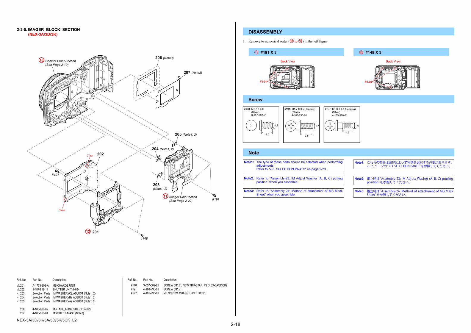
2-2-5. IMAGER BLOCK SECTION (NEX-3A/3D/3K) DISASSEMBLY
0 201 A-1773-803-A MB CHARGE UNIT0 202 1-487-619-11 SHUTTER UNIT (H094)* 203 Selection Parts IM WASHER (C), ADJUST (Note1, 2)* 204 Selection Parts IM WASHER (B), ADJUST (Note1, 2)* 205 Selection Parts IM WASHER (A), ADJUST (Note1, 2)
206 4-185-968-02 MB TAPE, MASK SHEET (Note3) 207 4-185-966-01 MB SHEET, MASK (Note3)
#148 3-057-082-21 SCREW (M1.7), NEW TRU-STAR, P2 (NEX-3A/3D/3K) #191 4-188-735-01 SCREW (M1.7) #197 4-185-990-01 MB SCREW, CHARGE UNIT FIXED
1. Remove to numerical order (qa to qd) in the left figure.
Note
qa #191 X 3 qs #148 X 3
Screw
Note2: Refer to “Assembly-23: IMAdjustWasher (A,B,C) puttingposition”whenyouassemble.
Note2: 組立時は“Assembly-23: IM Adjust Washer (A, B, C) putting position”を参照してください。
Note3: Refer to “Assembly-24:Methodof attachment ofMBMaskSheet”whenyouassemble.
Note3: 組立時は“Assembly-24: Method of attachment of MB Mask Sheet”を参照してください。
#148
Back View
Note1: Thetypeofthesepartsshouldbeselectedwhenperformingadjustments.
Referto"2-3.SELECTIONPARTS"onpage2-23.
Note1: これらの部品は調整によって種類を選択する必要があります。 2 - 23ページの“2-3. SELECTION PARTS”を参照してください。
#191
Back View
#148: M1.7 X 3.0(Silver)3-057-082-21
3.0
1.7
#191: M1.7 X 3.5 (Tapping)(Black)4-188-735-01
3.5
1.7
#197: M1.6 X 4.5 (Tapping)(Silver)4-185-990-01
4.5
1.6
206 (Note3)
#197
202
qs�201#148
qa�Imager Unit Section(See Page 2-22) #191
203(Note1, 2)
204 (Note1, 2)
205 (Note1, 2)
207 (Note3)
qd�Cabinet Front Section(See Page 2-19)
Claw
Claw

NEX-3A/3D/3K/5A/5D/5K/5CK_L22-19
Ref. No. Part No. Description Ref. No. Part No. Description
251 4-185-964-03 MB N PLATE (A)* 252 4-185-962-01 MB N PLATE (B)* 253 4-185-963-01 MB N PLATE SP (Note1) 254 4-189-512-01 RING (210), ORNAMENTAL* 255 4-186-534-01 BUTTON, L LOCK (BLACK)
* 255 4-186-534-21 BUTTON, L LOCK (RED)* 255 4-186-534-31 BUTTON, L LOCK (WHITE)* 255 4-186-534-41 BUTTON, L LOCK (SILVER)* 256 X-2547-937-1 PIN ASSY, L LOCK* 257 4-186-538-01 SPRING, LENS LOCK
258 4-189-412-01 GRIP (210) (BLACK) (Note5) 258 4-189-412-11 GRIP (210) (SILVER) (Note5) 258 4-189-412-21 GRIP (210) (RED) (Note5) 258 4-189-412-31 GRIP (210) (WHITE) (Note5) 259 4-189-413-01 SHEET (210), GRIP ADHESIVE
260 X-2548-232-1 CABINET (FRONT) ASSY (210B) (BLACK) (Note3) 260 X-2548-233-1 CABINET (FRONT) ASSY (210S) (SILVER) (Note3) 260 X-2548-234-1 CABINET (FRONT) ASSY (210R) (RED) (Note3) 260 X-2548-235-1 CABINET (FRONT) ASSY (210W) (WHITE) (Note3)* 261 4-196-544-01 TAPE (AS (210))
* 262 4-189-417-01 BRACKET (L), STRAP (210)* 263 4-193-982-01 WASHER, MF 264 A-1773-802-A MB CONTACT UNIT, N (Note2, 4)
#23 3-080-204-11 SCREW, TAPPING, P2 #148 3-057-082-21 SCREW (M1.7), NEW TRU-STAR, P2 #195 3-197-324-01 M1.7X2.5X3GF (D4X0.5) #198 4-186-545-01 M1.7X4 SPIN #199 4-195-871-01 SCREW, 0+Z M1.7
Note
2-2-6. CABINET FRONT SECTION (NEX-3A/3D/3K)
ns:notsupplied
Screw
Note1: Refer to “Assembly-27:Apply greaseonMBNPlateSP”whenyouassemble.
Note1: 組立時は“Assembly-27: Apply grease on MB N Plate SP”を参照してください。
Note2: Refer to “Assembly-28:MBNContactUnitholdingposition”whenyouassemble.
Note2: 組立時は“Assembly-28: MB N Contact Unit holding position”を参照してください。
#23:M1.7 X 4.0 (Tapping)(Black)3-080-204-11
4.0
1.7
#148: M1.7 X 3.0(Silver)3-057-082-21
3.0
1.7
2.5
1.7
#195: M1.7 X 2.5(Silver)3-197-324-01
4.0
1.7
#198: M1.7 X 4.0(Silver)4-186-545-01
3.0
1.7
#199: M1.7 X 3.0(Black)4-195-871-01
#23
257
256255
254
253(Note1)
252
251
#195
#198
258(Note5)
259 260 (Note3)
#148
#148
264(Note2, 4)
263
#199
262
261
ns
ns
ns
Claw
Note3: Refer to “PRECAUTIONONREPLACINGTHECABINETFRONT”onpage1-1whenreplacingCabinet(Front)Assy.
Note3: 前キャビネットAssyを交換する場合,1 - 1 ページの “PRECAUTION ON REPLACING THE CABINET FRONT”を参照
してください。
Note4: Refer to “PRECAUTIONONREPLACINGTHECABINETFRONT”onpage1-1whenreplacingMBNContactUnit.
Note4: MB N 接点ユニットを交換する場合,1 - 1 ページの “PRECAUTION ON REPLACING THE CABINET FRONT”を参照
してください。
Note5: グリップ(210)を取り外す場合,爪を破損しない為に,分解手順9BTフレームAssy(210)を取り外してから作業を行ってください。
Note5: Toavoiddamagingtheclaws,remove9BTFrameAssy(210)beforeremovingGrip(210).

NEX-3A/3D/3K/5A/5D/5K/5CK_L22-20
Ref. No. Part No. Description Ref. No. Part No. Description
301 X-2548-251-1 FRAME ASSY (210)* 302 4-186-555-01 LIGHT (LC), GUIDE,0 303 A-1779-038-A PANEL BLOCK ASSY (BLACK)0 303 A-1779-732-A PANEL BLOCK ASSY (SILVER)0 303 A-1779-733-A PANEL BLOCK ASSY (RED)
0 303 A-1779-734-A PANEL BLOCK ASSY (WHITE)* 304 4-190-763-01 BRACKET (G), STRAP (210)
305 4-186-571-01 SHEET, LC LIGHT INTERCEPTION* 306 4-195-258-01 SHAFT, CUSHION (MF) (Note1)
#148 3-057-082-21 SCREW (M1.7), NEW TRU-STAR, P2 #192 4-188-736-01 SCREW (TP1.4), P2 #196 4-178-124-01 SPECIAL (M1.4 (D2.75)) (RED, BLACK) (Note2) #201 4-178-124-21 SPECIAL (M1.4 (D2.75)) (SILVER, WHITE) (Note2)
Note
2-2-7. MAIN FRAME SECTION (NEX-3A/3D/3K)
ns:notsupplied
Screw
Note1: Refer to “Assembly-8:ShaftCushion (MF)puttingposition”whenyouassemble.
Note1: 組立時は“Assembly-8: Shaft Cushion (MF) putting position”を参照してください。
Note2: Refer to “THECOMBINATIONOFCABINET’SCOLORANDSCREW (NEX-3A/3D/3K)” onpage2-12about thecombinationofcabinet’scolorandscrew.
Note2: キャビネット色とネジの組合わせについては,2 - 12 ページの“THE COMBINATION OF CABINET’S COLOR AND SCREW (NEX-3A/3D/3K)”を参照してください。
#148: M1.7 X 3.0(Silver)3-057-082-21
3.0
1.7
#192: M1.4 X 4.0 (Tapping)(Black)4-188-736-01
4.0
1.4
#196: M1.4 X 2.0(Black)4-178-124-01
2.0
1.4
#201: M1.4 X 2.0(Silver)4-178-124-21
2.0
1.4
#196#201(Note2)
#148
304
302
305#192
ns
ns
301306 (Note1) 303

NEX-3A/3D/3K/5A/5D/5K/5CK_L22-21
Ref. No. Part No. Description Ref. No. Part No. Description
351 X-2548-275-1 HOLDER ASSY, SY (210B) (BLACK) 351 X-2548-276-1 HOLDER ASSY (210S), SY (SILVER) 351 X-2548-277-1 HOLDER ASSY (210R), SY (RED) 351 X-2548-278-1 HOLDER ASSY (210W), SY (WHITE) 352 X-2548-655-1 LID ASSY (210B) (SERVICE), BT (BLACK)
352 X-2548-656-1 LID ASSY (210S) (SERVICE), BT (SILVER) 352 X-2548-657-1 LID ASSY (210R) (SERVICE), BT (RED) 352 X-2548-658-1 LID ASSY (210W) (SERVICE), BT (WHITE) 353 X-2548-292-1 COVER ASSY, HDMI (210B) (BLACK) 353 X-2548-293-1 COVER ASSY (210S), HDMI (SILVER)
353 X-2548-294-1 COVER ASSY (210R), HDMI (RED)
353 X-2548-295-1 COVER ASSY (210W), HDMI (WHITE) 354 X-2548-288-1 COVER ASSY, USB (210B) (BLACK) 354 X-2548-289-1 COVER ASSY (210S), USB (SILVER) 354 X-2548-290-1 COVER ASSY (210R), USB (RED)
354 X-2548-291-1 COVER ASSY (210W), USB (WHITE) 355 4-190-890-01 CLAW, BT LOCK (210)* 356 4-186-558-01 PLATE, SHOE COVER* 357 4-190-893-01 SHAFT (210), BT LID 358 4-186-475-01 SPRING, BT LID OPEN (Note1)
359 4-190-961-01 LABEL (210), MS* 360 4-209-617-01 HOLDER,SHEET(SY)
Note2-2-8. SY HOLDER SECTION(NEX-3A/3D/3K)
ns:notsuppliedNote1: Referto“Assembly-6:MethodofattachmentofBTLidAssy”
whenyouassemble.Note1: 組立時は“Assembly-6: Method of attachment of BT Lid Assy”
を参照してください。
356
360
353
ns
359
357
351
358 (Note1)
352
355
354
NEX-3A/3D/3K/5A/5D/5K/5CK_L22-22
Ref. No. Part No. Description Ref. No. Part No. Description
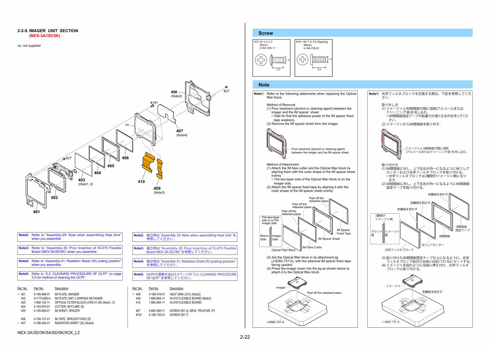
* 401 4-185-996-01 IM PLATE, IMAGER 402 A-1773-805-A IM PLATE UNIT, LOWPASS RETAINER 403 1-856-102-11 OPTICAL FILTER BLOCK (OFB-01-09) (Note1, 5) 404 4-193-875-01 CUTTER, IM FLARE (S) 405 4-185-993-01 IM SHEET, SPACER
406 4-194-127-01 IM TAPE, SPACER FIXED (S)* 407 4-186-454-01 RADIATION SHEET (IS) (Note4)
* 408 4-189-415-01 HEAT SINK (210) (Note2) 409 1-880-963-11 IS-075 FLEXIBLE BOARD (Note3) 410 1-880-964-11 IS-076 FLEXIBLE BOARD
#27 2-662-396-11 SCREW (M1.4), NEW, TRUSTAR, P2 #191 4-188-735-01 SCREW (M1.7)
Note
2-2-9. IMAGER UNIT SECTION (NEX-3A/3D/3K)
ns:notsupplied
Screw#27:M1.4 X 2.0
(Black)2-662-396-11
2.0
1.4
#191: M1.7 X 3.5 (Tapping)(Black)4-188-735-01
3.5
1.7
#27
#191
ns
401
402
405
406
410
407(Note4)
409(Note3)
#27408(Note2)
403(Note1, 5)
404
Note2: Refer to “Assembly-29:NotewhenassemblingHeatSink”whenyouassemble.
Note2: 組立時は“Assembly-29: Note when assembling Heat Sink”を参照してください。
Note3: Refer to “Assembly-30:Prior Insertionof IS-075FlexibleBoard(NEX-3A/3D/3K)”whenyouassemble.
Note3: 組立時は“Assembly-30: Prior Insertion of IS-075 Flexible Board (NEX-3A/3D/3K)”を参照してください。
Note4: Referto“Assembly-31:RadiationSheet(IS)puttingposition”whenyouassemble.
Note4: 組立時は“Assembly-31: Radiation Sheet (IS) putting position”を参照してください。
Note5: Referto“3-2.CLEANINGPROCEDUREOFOLPF”onpage3-5formethodofcleaningtheOLPF.
Note5: OLPFの清掃方法は3-5ページの“3-2. CLEANING PROCEDURE OF OLPF”を参照してください。
Note1: RefertothefollowingstatementswhenreplacingtheOpticalfilterblock.
MethodofRemoval (1)Pourresolvent(alcoholorcleaningagent)betweenthe imagerandtheIMspacersheet. *WaitforthattheadhesivepoweroftheIMspacerfixed tapeweakens. (2)RemovetheIMspacersheetfromtheimager.
Pour resolvent (alcohol or cleaning agent)between the imager and the IM spacer sheet.
MethodofAttachment (1)AttachtheIMflarecutterandtheOpticalfilterblockby aligningthemwiththeoutershapeoftheIMspacersheet evenly. *Thetwo-layersideoftheOpticalfilterblockisonthe imagerside. (2)AttachtheIMspacerfixedtapebyaligningitwiththe outershapeoftheIMspacersheetevenly.
The two-layerside is on theimager side.
MountSide
ImagerSide
Optical Filter Block
Peel off thereleased paper.
Peel off thereleased paper.
Peel off thereleased paper.
IM Flare Cutter
IM Spacer Sheet
IM SpacerFixed Tape
(3)SettheOpticalfilterblockinitsattachmentjig (J-6082-737-A),withtheattachedIMspacerfixedtape facingupward. (4)Presstheimagerdownintothejigasshownbelowto attachittotheOpticalfilterblock.
J-6082-737-A
Imager
Peel off the released paper.
Note1: 光学フィルタブロックを交換する際は、下記を参照してください。
取り外し方 (1) イメージャとIM間隔板の間に溶剤(アルコールまたは クリーニング液)を流し込む。 * IM間隔板固定テープの粘着力が弱くなるのを待ってくだ さい。 (2) イメージャからIM間隔板を取り外す。
イメージャとIM間隔板の間に溶剤(アルコールまたはクリーニング液)を流し込む。
取り付け方 (1) IM間隔板に対し、上下左右が均一になるようにIMフレア カッターおよび光学フィルタブロックを貼り付ける。 * 光学フィルタブロックは2層側がイメージャ側になり ます。 (2) IM間隔板に対し、上下左右が均一になるようにIM間隔板 固定テープを貼り付ける。
2層側がイメージャ側
マウント側
イメージャ側
光学フィルタブロック
剥離紙を剥がす
剥離紙を剥がす
剥離紙を剥がす
IMフレアカッター
IM間隔板
IM間隔板固定テープ
(3) 貼り付けたIM間隔板固定テープが上になるように、光学 フィルタブロック貼付け治具(J-6082-737-A)にセットする。 (4) イメージャを図のように治具に押え付け、光学フィルタ ブロックに貼り付ける。
J-6082-737-A
イメージャ
剥離紙を剥がす

NEX-3A/3D/3K/5A/5D/5K/5CK_L22-23E
Checking supplied accessories.Note: Thisitemissuppliedwiththeunitasan accessory,butisnotpreparedasaservicepart.
4-185-999-01 IM WASHER (C), ADJUST (t = 0.05)4-185-999-11 IM WASHER (C), ADJUST (t = 0.1)4-185-999-21 IM WASHER (C), ADJUST (t = 0.15)4-185-999-31 IM WASHER (C), ADJUST (t = 0.2)4-185-999-41 IM WASHER (C), ADJUST (t = 0.25)4-185-999-51 IM WASHER (C), ADJUST (t = 0.3)4-185-999-61 IM WASHER (C), ADJUST (t = 0.35)4-185-999-71 IM WASHER (C), ADJUST (t = 0.4)4-185-999-81 IM WASHER (C), ADJUST (t = 0.45)4-185-999-91 IM WASHER (C), ADJUST (t = 0.495)
Part No. Description
4-185-998-01 IM WASHER (B), ADJUST (t = 0.05)4-185-998-11 IM WASHER (B), ADJUST (t = 0.1)4-185-998-21 IM WASHER (B), ADJUST (t = 0.15)4-185-998-31 IM WASHER (B), ADJUST (t = 0.2)4-185-998-41 IM WASHER (B), ADJUST (t = 0.25)4-185-998-51 IM WASHER (B), ADJUST (t = 0.3)4-185-998-61 IM WASHER (B), ADJUST (t = 0.35)4-185-998-71 IM WASHER (B), ADJUST (t = 0.4)4-185-998-81 IM WASHER (B), ADJUST (t = 0.45)4-185-998-91 IM WASHER (B), ADJUST (t = 0.495)
4-185-995-01 IM WASHER (A), ADJUST (t = 0.05)4-185-995-11 IM WASHER (A), ADJUST (t = 0.1)4-185-995-21 IM WASHER (A), ADJUST (t = 0.15)4-185-995-31 IM WASHER (A), ADJUST (t = 0.2)4-185-995-41 IM WASHER (A), ADJUST (t = 0.25)4-185-995-51 IM WASHER (A), ADJUST (t = 0.3)4-185-995-61 IM WASHER (A), ADJUST (t = 0.35)4-185-995-71 IM WASHER (A), ADJUST (t = 0.4)4-185-995-81 IM WASHER (A), ADJUST (t = 0.45)4-185-995-91 IM WASHER (A), ADJUST (t = 0.495)
Part No. Description
Part No. Description
2-3. SELECTION PARTS
Ref. No.203Select the optimum thickness of washer.
Ref. No.204Select the optimum thickness of washer.
Ref. No.205Select the optimum thickness of washer.
The CD-ROM supplied contains all of language version ofthe α Handbook (PDF) for printing.・The printed matter is not supplied. If required,please order it with the part number below.
・(Only for destination Japanese model) 日本国内については日本語のみが印刷での部品供給可能です。
Power cord (mains lead)0 1-832-121-51 (CH) (NEX-5CK)0 1-837-421-11 (UK, E (Saudi, Hong Kong))0 1-837-422-11 (JE)0 1-837-427-11 (AEP, E (EXCEPT Saudi, Hong Kong))0 1-837-428-11 (KR)0 1-837-429-11 (AUS)
Rechargeable battery pack(NP-FW50)(Note)
USB cable1-829-868-31
Shoulder strap4-188-538-01
Body cap(Note)
α Handbook (PDF)
CD-ROM- Application Software for α camera- α Handbook
NEX-3A/3D/3K4-191-926-01
NEX-5A/5D/5K/5CK4-191-823-01
Battery charger(BC-VW1)0 1-487-907-11 (J)0 1-487-907-21 (US, CND)0 1-487-907-41 (EXCEPT US, CND, J)
Conversion (2P) Adaptor0 1-569-008-33
(E (Southeast Asia, Taiwan & Latin Area))
4-183-855-01 (JAPANESE)* 4-183-855-11 (ENGLISH)* 4-183-855-21 (FRENCH)* 4-183-855-31 (ITALIAN)* 4-183-855-41 (SPANISH)* 4-183-855-51 (PORTUGUESE)* 4-183-855-61 (GERMAN)* 4-183-855-71 (DUTCH)* 4-183-855-81 (TRADITIONAL CHINESE)* 4-183-855-91 (SIMPLIFIED CHINESE)* 4-189-192-11 (RUSSIAN)* 4-189-192-21 (ARABIC)
Conversion (2P) Adaptor0 1-569-007-12 (JE)
FlashA-1774-691-A
Flash case4-186-787-01
* 4-189-192-31 (PERSIAN)* 4-189-192-41 (KOREAN)* 4-189-192-51 (POLISH)* 4-189-192-61 (CZECH)* 4-189-192-71 (HUNGARIAN)* 4-189-192-81 (SLOVAK)* 4-189-192-91 (SWEDISH)* 4-189-193-11 (FINNISH)* 4-189-193-21 (NORWEGIAN)* 4-189-193-31 (DANISH)* 4-189-193-41 (THAI)* 4-189-193-51 (UKRAINIAN)
Instruction Manual(Only for destination Japanese model)日本語、英語、韓国語、中国語のみ部品供給可能です。
4-183-856-01 (JAPANESE)4-183-856-11 (ENGLISH)
* 4-183-856-22 (FRENCH, ITALIAN)* 4-183-856-31 (SPANISH, PORTUGUESE)* 4-183-856-42 (GERMAN, DUTCH)* 4-183-856-51 (TRADITIONAL CHINESE,
SIMPLIFIED CHINESE) (E)* 4-183-856-61 (RUSSIAN)* 4-183-856-71 (ARABIC, PERSIAN)
4-183-856-81 (KOREAN)4-183-856-91 (SIMPLIFIED CHINESE)
(CH) (NEX-5CK)* 4-183-857-11 (POLISH)

NEX-3A/3D/3K/5A/5D/5K/5CK_L23-1
3. ASSEMBLY
Frame Assy
Before assembling Frame Assy, temporally secureFP-1237 Flexible Complete Board.
FP-1237 Flexible Complete Board
Edge ofFrame Assy
Assembly-2: Temporally secureFP-1237 Flexible Complete Board
Assembly-3: Insulating Sheet A (SY) putting position
Insulating Sheet A (SY)
Align with the upperedge of the connector.
Align with the right edgeof the connector.
Align with thelower edgeof the ground.
Assembly-4: LC Flexible Insulating Sheetputting position
Ground
FP-1237 Complete BoardLC Flexible Insulating Sheet
Assembly-5: LC Connector Insulating Sheet,LC Flexible Insulating Sheetputting position
LC Connector Insulating Sheet
LC Flexible Insulating Sheet
Without running on the edge.
LC Cabinet (Rear) Assy
BT Lid Assy
Assembly-6: Method of attachment of BT Lid Assy
BT Lid Shaft
Cabinet (Rear) Assy
BT Lid OpenSpring
B
A
AB
Tighten the four screws in sequence of 1 to 4 as shown below.
Cabinet (Rear) Assy
Cabinet (Front) Assy
Assembly-7: Screw tightening sequence whenassembling the exterior parts(NEX-3A/3D/3K)
Tighten the two screws in sequence of 1 to 2 as shown below.
Grip (210)
1
2
Tighten the five screws in sequence of 1 to 5 as shown below.
Front Cabinet Assy
Rear Cabinet Assy
12
3 4
5
Side Cover (210)
1
23
4
Assembly-8: Shaft Cushion (MF) putting position
Frame Assy
Without runningon the mold part.
Shaft Cushion (MF)
Assembly-1: Method of attachment ofCabinet (Rear) Assy
Open the LCD as shown below.
Fit the Cabinet (Rear) Assy along the angle of LCD.
Incline Cabinet (Rear) Assy while turning it counterclockwise,then fit it in LCD.

NEX-3A/3D/3K/5A/5D/5K/5CK_L23-2
LC Flexible Insulating Sheet
Without running on theblack printing area onFP-1237 Flexible CompleteBoard
Without running off theedge of FP-1237 FlexibleComplete Board
FP-1237 Flexible Complete Board
Assembly-9: LC Flexible Insulating Sheetputting position
Insulating Sheet B (SY)
SY-258 Complete Board Without running on the chip.
Assembly-10: Insulating Sheet B (SY) putting position
Assembly-11: Routing of Microphone Harness
Insert the surplus partinto the Front Cabinet.
Pass the harnesses through thecorner of SY-258 Complete Board.
SY-258 Complete Board
MicrophoneHarness
CN-439Complete Board
BT Frame Assy
Insert Gasket (MS) between BT Frame Assy andCN-439 Complete Board without evagination.
Assembly-12: Inserting Gasket (MS)(NEX-5A/5D/5K/5CK)
Gasket (MS)
BT Holder Block AssyShutter Unit
Assembly-13: Assemble BT Holder Block Assy(NEX-5A/5D/5K/5CK)
Shutter Flexible Board
Assembly-14: Routing of Microphone Harness(NEX-5A/5D/5K/5CK)
SP Holder Route the part shown withbroken line inside SP Holder.
RL Block AssyMicrophone Harness
NEX-5A/5D/5K/5CK
Assembly-15: Lithium Rechargeable Batteryputting position
NEX-3A/3D/3KPrinting shows position ofLithium Rechargeable Battery
Printing shows positionof Lithium RechargeableBattery
Soldering
Soldering
RL-103 Complete BoardLithium Rechargeable Battery
Lithium Rechargeable Battery RL-101 Complete Broad
Note: Make sure that the PW Knob isturned to OFF position whenassembling RL Block Assy.
RL Block Assy
PW Knob
Assembly-16: Note when assemblingRL Block Assy(NEX-5A/5D/5K/5CK)
Assembly-17: Note on Alignment of the Flexible Boardwhen assembling SY Holder Block Assy(NEX-3A/3D/3K)
SY HolderBlock Assy
Outside SY HolderBlock Assy
Under SY HolderBlock Assy
Above SY HolderBlock Assy
Between Shutter Unitand SY Holder Block AssyUnder SY Holder
Block Assy
Radiation Sheet (SY) (210)
SY-258 Complete Board
Attach Radiation Sheet (SY) (210) on SY-258 CompleteBoard without running off more than two corners of the IC.
Assembly-18: Radiation Sheet (SY) (210)putting position(NEX-3A/3D/3K)
Jack Cover BaseUnder Jack Cover Base
Above Jack Cover Base
Assembly-19: Note on Alignment of the Flexible Boardwhen assembling Jack Cover Base(NEX-5A/5D/5K/5CK)

NEX-3A/3D/3K/5A/5D/5K/5CK_L23-3
Assembly-20: Routing of Microphone Harness(NEX-3A/3D/3K)
Microphone
Cabinet (Upper) Assy
Insert the surplus part intothe hole as shown here.
Route the harnesses under thetwo ribs of Cabinet (Upper) Assy.
Cabinet (Upper) Assy
RL Block Assy
Note: Make sure that the PW Knobis turned to OFF positionwhen assembling Cabinet(Upper) Assy to RL BlockAssy.
PW Knob
Assembly-21: Assemble Cabinet (Upper) Assy(NEX-3A/3D/3K)
Assembly-22: Radiation Sheet (CN) (210)putting position(NEX-3A/3D/3K)
CN-439 Complete Board
FP-1246Flexible Board
Radiation Sheet(CN) (210)
Within 1.0mm
Without running on thereinforcement board
Within 1.0mm
Cabinet (Front)
IM Adjust Washer B IM Adjust Washer A
IM Adjust Washer C
Assembly-23: IM Adjust Washer (A, B, C)putting position
Assembly-25: BT Slider Sheet (front) putting position(NEX-5A/5D/5K/5CK)
BT Slider Sheet (front)
Rib edge (horizontal):±0.5mm
Rib edge (vertical):±0.5mm
Lib edge (vertical):±0.5mm
MB N Plate SP
Assembly-27: Apply grease on MB N Plate SP
G G-85(J-6082-626-A)
BT Slider Sheet(horizontal)
Cabinet (Front)
Assembly-26: BT Slider Sheet (horizontal)putting position(NEX-5A/5D/5K/5CK)
From edge(vertical):±1.0mm
From edge(horizontal):±1.0mm
J-6082-735-A
MB Mask Sheet
Note: There should not be any misalignment when attachingMB Mask Sheet.
MB MaskSheet Tape
Cabinet (Front)
Assembly-24: Method of attachment of MB Mask Sheet

NEX-3A/3D/3K/5A/5D/5K/5CK_L23-4
Hold here
Assembly-28: MB N Contact Unit holding position
MB N Contact Unit
Insert IS-075 Flexible Board into the connector onIM Imager Unit 14M, then lock the connector.
Assemble Heat Sink and IM Imager Unit 14M.
Note: IS-075 Flexible Board can not be inserted afterassembling Heat Sink.
Heat Sink
IM Imager Unit 14M
IS-075 Flexible Board
Assembly-30: Prior Insertion of IS-075 Flexible Board(NEX-3A/3D/3K)
Radiation Sheet (IS)
Heat Sink
Without running off theedge of the hole.
Without running on theedge of Heat Sink.
Assembly-31: Radiation Sheet (IS) putting position
SY-258 Complete Board
CN-439 Complete BoardPut the surplus part of theshutter flexible board underSY-258 Complete Board.
Assembly-32: How to handle the Shutter Flexible Board(NEX-3A/3D/3K)
Assembly-29: Note when assembling Heat Sink
Align with the positioning hole.
Heat Sink
CN-439Complete Board
LC ConnectorInsulating Sheet
BT Frame Assy
Within 0.5mm
Within 0.5mm
Assembly-33: LC Connector Insulating Sheetputting position
Assembly-34: Tape AS (210) putting position(NEX-5A/5D/5K/5CK)
Tape AS (210)
Without protrudingfrom the rib top surface.
Without running offthe mask sheet.
Without running on this boss.
Assembly-35: Method of attachment of LC FlexibleInsulating Sheet(NEX-3A/3D/3K)
Bend the LC Flexible Insulating Sheet alongthe curve of BT-063 Flexible Board.
LC FlexibleInsulating Sheet
±1.0mm
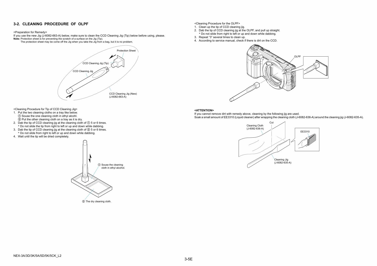
NEX-3A/3D/3K/5A/5D/5K/5CK_L23-5E
3-2. CLEANING PROCEDURE OF OLPF
<Preparation for Remedy>If you use the new Jig (J-6082-663-A) below, make sure to clean the CCD Cleaning Jig (Tip) below before using, please.Note: Protection sheet is for preventing the scratch of a surface on the Jig (Tip). The protection sheet may be come off the Jig when you take the Jig from a bag, but it is no problem.
<ATTENTION>If you cannot remove dirt with remedy above, cleaning by the following jig are used.Soak a small amount of EE3310 (Liquid cleaner) after wrapping the cleaning cloth (J-6082-636-A) around the cleaning jig (J-6082-635-A).
<Cleaning Procedure for Tip of CCD Cleaning Jig>1. Put the two cleaning cloths on a tray like below. 1 Souse the one cleaning cloth in ethyl alcohl. 2 Put the other cleaning cloth on a tray as it is dry.2. Dab the tip of CCD cleaning jig at the cleaning cloth of 1 5 or 6 times. * Do not slide the tip from right to left or up and down while dabbing.3. Dab the tip of CCD cleaning jig at the cleaning cloth of 2 5 or 6 times. * Do not slide from right to left or up and down while dabbing.4. Wait until the tip will be dried completely.
<Cleaning Procedure for the OLPF>1. Clean up the tip of CCD cleaning jig.2. Dab the tip of CCD cleaning jig at the OLPF, and pull up straight. * Do not slide from right to left or up and down while dabbing.3. Repeat “3” several times to clean up.4. According to service manual, check if there is dirt on the CCD.
CCD Cleaning Jig (New)(J-6082-663-A)
CCD Cleaning Jig
CCD Cleaning Jig (Tip)
Protection Sheet
1 Souse the cleaningcloth in ethyl alcohol.
2 The dry cleaning cloth.
OLPF
Cleaning Jig(J-6082-635-A)
Cleaning Cloth(J-6082-636-A)
Cut
EE3310