sound card oscilloscopes - philmonthf digital handbook, 4th edition, steve ford, wb8imy (arrl) get...
TRANSCRIPT

Sound Card Oscilloscopes and Digital Modes
K3EUI
Barry Feierman June 2016

Hardware for Digital Modes Interface - between computer and radio by two audio cables or by a single usb cable Sound Card INPUT - from speaker/headphone or DATA jack (constant vol) Sound Card OUTPUT – to MIC or Data jack PTT - usb/serial or VOX (SignaLink) GND - common ground cable Goals: set proper RX and TX levels optical isolation of audio lines avoid RF feedback

Tigertronics SignaLink (usb) both RX and TX audio connects to DATA jack or MIC jack
cost about $100

Rigblaster: uses sound chips in computer allows for L/R/both audio for TX Designed to plug into a MIC jack
VOX or PTT circuit via a COM port cost about $50 used market

Rigblaster “Advantage” usb port with built-in low-noise sound chips
cost about $150

Simple Rigblaster “nomic” only handles sound card TX audio (no mic connection)
cost well under $100

External USB Sound Blaster usb hardware very high quality, low-noise sound chips ($100)

Simple 2-cond shielded cable with TX and RX audio via 1:1 isolation transformers

What is the “best” interface?

Oscilloscopes
How do hams use these in the radio shack?
(stand up if you have a “scope” in your shack)
Physical Oscilloscopes vs. Sound Card Oscilloscopes
analog with CRT beam vs. Digital and LCD display
useful frequency range (Radio frequencies vs. audio freq)
cost comparison
Tektronics scope 50 MHz about $500
Rigol scope 50 MHz about $350
Sound Card (audio) Oscilloscope - most are FREE

What is a “sound card oscilloscope” ?

An oscilloscope is just a fast graphic voltmeter allowing you to “see”
the shapes of AC voltages over time
You can use an oscilloscope to
measure period or frequency measure peak voltages measure rise/fall times check for clipping check for harmonics

Most modern oscilloscopes can do “math” functions
like a FFT calculation to plot a frequency spectrum
“Fast Fourier Transform” breaks up a complex wave into its sine-
wave components

Sound Card Oscilloscopes
use the PC’s built in soundcard for the audio analog/digital (A/D) conversion

How can we use Sound Card Oscilloscope apps with our radios? Examine shapes of RX and TX signals Examine audio bandpass Look for 60 Hz hum Examine the envelopes of digi signals

Oscilloscope apps for Windows machines
Christian Zeitnitz: Sound Card Scope


DL4YHF Spectrum Lab

Spectrum Labs Sound Card Oscilloscope
More powerful FFT analysis
Finer resolution in Hz bins
Larger Screen Size
Many more options for averaging
Needs a faster processor

Zeitnitz’s Settings: choose sound card input and output, Y and X scale values, type of triggering, channel (L/R)

Oscilloscope Screen: Y = amplitude X = time 100 Hz sine wave: 2 volts peak/peak: 10 ms period

Viewing the frequency distribution (FFT) of a 100 Hz sine wave, looking for harmonics

Oscilloscope Screen: 100 Hz “square wave” A square wave has many “odd” harmonics

Frequency Distribution of 100 Hz square wave note all “odd” order harmonics (100,300,500,700 Hz)

Oscilloscope View: “White Noise” has no periodicity, no noticeable pitch

Frequency Distribution of White Noise 0 – 20 kHz (equal energy everywhere)

Frequency Distribution: Pink Noise 0 to 20 kHz

Bandpass of a typical SSB radio: Yaesu FT 1000 (1990) in USB mode (400 – 2600 Hz bandpass)

Bandpass of a typical FM radio 0 – 4000 Hz Why the gradual decline of intensity with frequency?

What is the bandwidth of an RF carrier with no modulation?
(often called a “dead” carrier)

Modulation: adding information to a carrier 3 ways to modulate a carrier 1) amplitude changes (AM) 2) frequency or angle changes (FM) 3) phase changes (PM)

What MODE is
on/off
amplitude-shift-keying?

CW of course In CW a “carrier” (EM wave) is keyed on/off producing in a receiver equipped with a bfo the sounds we call “dit and dah” Morse Code So CW is a digital mode in the sense that a machine can interpret the ON/OFF sounds as 0’s and 1’s Spaces (no sound) = 0’s tone on = 1 000 between letters, 0000000 between words 1 dah = 3 dits (3:1 typical ratio) letter binary equivalent Dit e = 10 Dah t = 1110 Letter i = 1010 Letter m = 11101110 Letter o = 111011101110

Why is CW still such a popular mode of operation
especially for DX?

Advantages of CW
A good CW operator can copy CW when
the signal to noise ratio (S/N) is only 0 dB
The human ear/brain can detect and filter out the pitch you want in a qrm situation (pile up)
CW receive filters can be very narrow bandwidth (100 Hz)
and hence, improve the S/N and eliminate unwanted signals
*** do not use noise “blankers” or noise “clippers” ***

What is the minimum “bandwidth” of a CW signal operating at 30 wpm
What factors determine the “bandwidth” of a CW signal?
How might an oscilloscope help you transmit a cleaner CW signal ?

CW: dits (e) at 30 wpm note the 4 millisecond “rise/fall times”

Spectrum of a “clean” CW TX at 20 wpm center 1000 Hz 6 ms rise/decay times
bandwidth 200 Hz @ -50 dB
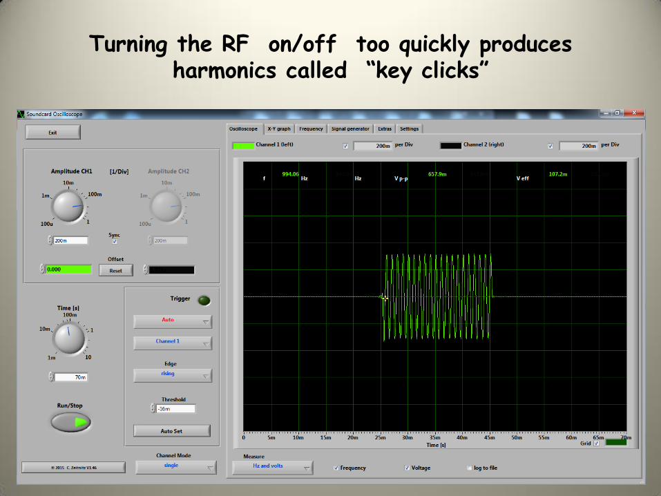
Turning the RF on/off too quickly produces harmonics called “key clicks”

Spectrum of CW TX 20 wpm with “hard keying” 1 ms rise/decay times - increased bandwidth
many sidebands - “key clicks”

“clean” CW received on 40 meters from K4DAL (Va) He was sending @20 wpm with a keyer and TenTec Jupiter
my RX IF bandwidth set for about 1 kHz
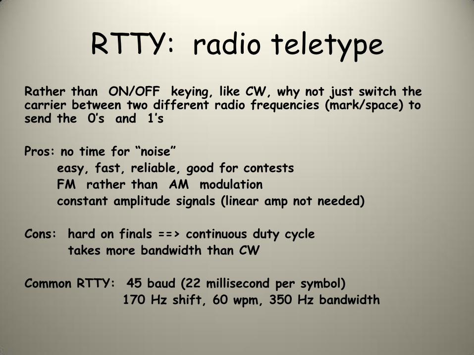
RTTY: radio teletype
Rather than ON/OFF keying, like CW, why not just switch the carrier between two different radio frequencies (mark/space) to send the 0’s and 1’s Pros: no time for “noise” easy, fast, reliable, good for contests FM rather than AM modulation constant amplitude signals (linear amp not needed) Cons: hard on finals ==> continuous duty cycle takes more bandwidth than CW Common RTTY: 45 baud (22 millisecond per symbol) 170 Hz shift, 60 wpm, 350 Hz bandwidth

Conventional two-tone RTTY 45 baud, 60 wpm, 400 Hz wide @ -60 dB

Problems with RTTY 45 on HF
Fading and phase delays due to changing ionospheric refraction (not reflection) of the EM wave
Poor on “long path” contacts around the world when you get “echo-like” signals
5 bit Baudot code ==> same time to send any character and no lower case, only UPPER CASE and numbers
No FEC or any kind of error detection

Data Rate vs. Symbol Rate
What if instead of binary modulation on/off CW (0/1)
or mark/space RTTY (0/1)
You use 4, 8, 16, or 32 different audio tones in each “symbol”?
Then each “symbol” could carry more information,
but needs more bandwidth, hence we have
MFSK, Olivia, Domino, THOR modes

Multi Frequency Modes
Each tone (sent one at a time) represents more data
MFSK 8/16/32/64/128 (3bit,4bit,5bit,6bit,7bit)
In F1B modes (FM) the amplitude shifts are ignored
and we find noise (qrn) is mostly amplitude shifts
MFSK is a very sensitive mode on HF bands like 80/40/20 meters, works well with low power and simple antennas

MFSK Oscilloscope View: energy vs. time nearly constant amplitude with frequency changes

MFSK32 Spectrum View: 500 Hz wide

Problems with MFSK
The sound card/processor must be able to distinguish one tone from its adjacent tone in the presence of HF “noise” and “phase distortion” in the ionosphere.
Hence, there is a minimum spacing between tones.
Switching tones too quickly (high baud) causes errors due to phase and time distortions produced by ionosphere
Popular HF MFSK modes
MFSK 8 (32 tones, 36 wpm, 316 Hz bandwidth)
MFSK 16 (16 tones, 58 wpm, 316 Hz bandwidth)
MFSK 32 (16 tones, 120 wpm, 630 Hz bandwidth)

Olivia (named after the author’s daughter)
Designed for copy under marginal S/N (-10 dB)
Has FEC (forward error correction)
Upper and Lower case
Resistant to qrn, qrm, qsb, frequency drift
Sounds like a calliope at a carnival
Speed, Tones and Bandwidth vary Olivia 4/8/16/32/64/128 number of tones (one at a time)
Olivia 125/250/500/1000/2000 Hz bandwidth
Olivia modes are 31 baud, 63 baud, or 125 baud

Olivia 8/500 Spectrum: 8 tones, 500 Hz bandwidth, 63 baud, 30 wpm
signal is 50 dB above baseline noise This is what a “clean” Olivia 8/500 signal should look like

Olivia 8/500 TX signal “over-driven” into ALC action bandwidth 1700 Hz @ -30 dB causes “splatter”

Distorted Olivia 8/500 signal received on 40 meters PA-NBEMS net
(you could hear scratchy sounds in headphones)

THOR Uses a type of modulation called “incremental frequency shift”
18 tones are sent one at a time at constant amplitude (F1B)
but the CHANGE IN PITCH from one tone to the next tone is what determines the symbol, not the actual pitch of the tone (MFSK, Olivia)
THOR is very tolerant of drift in your radio’s vfo or drift in your sound card’s oscillator (+/- 100 Hz is ok)
MODES: Thor 4,5,8,11,22,50,100 baud
Speed from 14 to 350 wpm
Secondary Channel: call, grid, etc.

THOR 22 Oscilloscope View nearly constant amplitude, 22 baud, 78 wpm, 524 Hz wide

THOR 22: Spectrum View

THOR 100 97 baud, 352 wpm, 1800 Hz bandwidth
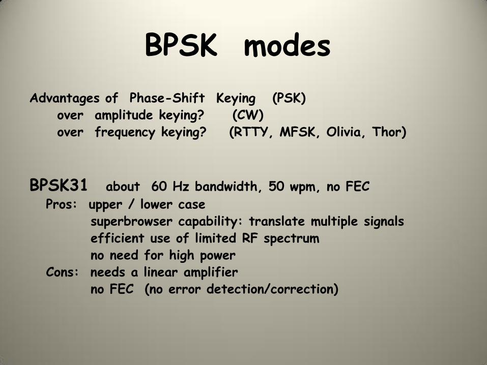
BPSK modes
Advantages of Phase-Shift Keying (PSK) over amplitude keying? (CW) over frequency keying? (RTTY, MFSK, Olivia, Thor)
BPSK31 about 60 Hz bandwidth, 50 wpm, no FEC
Pros: upper / lower case superbrowser capability: translate multiple signals efficient use of limited RF spectrum no need for high power Cons: needs a linear amplifier no FEC (no error detection/correction)

PSK31 Oscilloscope view: 32 ms per “symbol” 0 = phase shift 1=no phase shift

BPSK31 Spectrum View: bandwidth <100 Hz note slight 2nd and 3rd harmonic (down >30 dB)

“clean” BPSK31 TX with no ALC TX bandwidth 150 Hz @ -50 dB

Wide BPSK31 - TX driven into excessive ALC TX bandwidth 600 Hz @ -50 dB
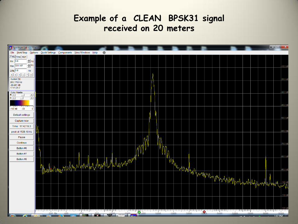
Example of a CLEAN BPSK31 signal received on 20 meters

Example of a distorted BPSK31 signal received on 20 meters

8PSK modes
Remember: BPSK is a two-state system (shift/no shift)
8 PSK modes employ shifts of
0, 45, 90, 135, 180, 225, 270, 315 degrees Each “symbol” contains more information: 8 “states” (3 bit) 8PSK1200F is almost 4000 words per minute Ideal on VHF/UHF FM to send long FLAMP files Ideal for ARES/RACES traffic Con: takes more bandwidth

8PSK500F Spectrum View note sidebands and “pilot tone” at 1000 Hz

Safety in Numbers?
BPSK31 is one carrier modulated at 31.25 baud 50 wpm
Why not send multiple simultaneous carriers each modulated with a psk information?
MT63 is born 64 carriers, each carrying an independent PSK signal
Choice of 5, 10, 20 baud (500, 1000, 1500 Hz wide)
Speeds of 50, 100, 200 wpm
Pros: Highly immune to noise
Works wonders on an FM repeater for ARES/RACES drills
Works on FM radios with “acoustic coupling”

MT63 - 500 in Oscilloscope View note the high peak to average rates

MT63 - 500 Spectrum 64 carriers, 5 baud, 50 wpm

Speed vs. Sensitivity
Highest sensitivity modes take more time to detect the signal from the “noise”
JT modes: JT65, JT9 Use special coding for the message but can work at S/N ratios of -24 dB but at only 3 wpm
(you can work the world with 1 watt and a dipole)

JT 65 Spectrum View 3 wpm but can be copied at -24 dB S/N

Other uses for C.Zeitnitz’s Sound Card Scope Two Channel Signal Generator
(sine, triangle, square waves, white noise)

Audio Recorder / Playback

Useful References
Oscilloscopes for Radio Amateurs, Paul Danzer N1ii (ARRL)
Sound Card Oscilloscopes QST Feb 2016
ARRL Handbook
HF Digital Handbook, 4th edition, Steve Ford, WB8IMY (ARRL)
Get on the Air with HF Digital, Steve Ford, WB8IMY (ARRL)
Work the World with JT65 and JT9, Steve Ford, WB8IMY (ARRL)