sound-lab a-1 electrostatic loudspeaker - monarchy...
TRANSCRIPT
1
FLOOR LOUDSPEAKER REVIEWS
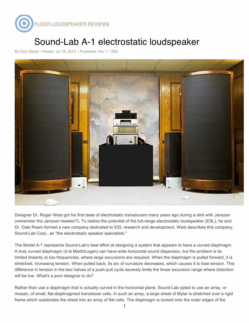
Sound-Lab A-1 electrostatic loudspeaker By Dick Olsher • Posted: Jul 18, 2013 • Published: Nov 1, 1992
Designer Dr. Roger West got his first taste of electrostatic transducers many years ago during a stint with Janszen (remember the Janszen tweeter?). To realize the potential of the full-range electrostatic loudspeaker (ESL), he and Dr. Dale Ream formed a new company dedicated to ESL research and development. West describes this company, Sound-Lab Corp., as "the electrostatic speaker specialists."
The Model A-1 represents Sound-Lab's best effort at designing a system that appears to have a curved diaphragm. A truly curved diaphragm (à la MartinLogan) can have wide horizontal sound dispersion, but the problem is its limited linearity at low frequencies, where large excursions are required. When the diaphragm is pulled forward, it is stretched, increasing tension. When pulled back, its arc of curvature decreases, which causes it to lose tension. This difference in tension in the two halves of a push-pull cycle severely limits the linear excursion range where distortion will be low. What's a poor designer to do?
Rather than use a diaphragm that is actually curved in the horizontal plane, Sound-Lab opted to use an array, or mosaic, of small, flat-diaphragmed transducer cells. In such an array, a large sheet of Mylar is stretched over a rigid frame which subdivides the sheet into an array of flat cells. The diaphragm is locked onto the outer edges of the

2
frame with a compound precision-molded clamp that assures no slippage of diaphragm tension over time. The cells are then arranged to form several long vertical facets positioned to approximate a curved surface. Sound-Lab's flat diaphragm ensures symmetrical behavior as it moves between the stators. Care is taken to keep the dead zone between facets down to 1/32". Further, to prevent an acoustic "venetian-blind" effect, the angle between adjacent facets is chosen so that the facets should integrate smoothly in the horizontal plane without lobes in the pressure response.
Any taut, underdamped membrane (eg, a drumhead) exhibits a significant fundamental resonance. Such drumhead resonances are undesirable in a speaker; the large peak (most often in the midbass) not only colors the sound, but also limits the speaker's usable dynamic range. The diaphragm can slap the stator electrodes and make nasty crunching sounds that sound little like music. Something must be done to control this resonance. Normally, resistive damping in the form of a cloth mesh or foam placed next to the stators controls diaphragm motion and reduces the Q of the resonance.
Sound-Lab's inventive approach, dubbed the "distributed bass resonance" principle, is protected under US patent. In this design, the diaphragm is physically subdivided into sectors in such a way as to stagger the sectors' resonance frequencies, spreading the bass resonance energy over a greater frequency range. As a result, the Q of the resonance is reduced, but as an added benefit, bass extension is improved. In the loudspeaker's nearfield, the bass response rises at a rate of about 6dB/octave, just enough to compensate for front-to-back dipole cancellation of bass energy for an octave or so below the diaphragm's drumhead resonant frequency. Farther into the room, in the far field, say 10' from the loudspeaker, the back wave wraps around the panel and neatly wipes out the array's inherent rising bass response. The result is a flatter, deeper bass response, marred only by the presence of the ubiquitous room modes.
The interface electronics package is housed in the speaker's base. An ultrasonic type of bias power supply is used, said to eliminate the power-line noise and hum typical of 50/60Hz supplies. A pair of step-up transformers is used to cover the audio spectrum. One transformer (actually two transformers connected in parallel) is primarily dedicated to the bass frequencies, while the other handles the upper range. The transformers overlap in the lower midrange. The interface was redesigned in Fall 1991 to improve the integration between the transformers and to increase the core saturation headroom. Better passive parts are also used. I can tell you from my own listening that an upgrade to the new interface is well worth the expense. Tonal balance in the lower midrange improved, as did midrange transparency. A similar interface upgrade is also available for the Sound-Lab A-3.
Three adjustment controls are provided on the back plate. The Brilliance control pot adjusts the treble level, the maximum position yielding the maximum high-treble sensitivity, counterclockwise rotation reducing the treble response. This control should be adjusted by ear, the optimum setting being a function of listening-room damping and front-end balance.
Control is also provided over the bass response, which can be shelved in 3dB steps relative to the midrange and treble. From the nominal 0dB bass setting, adjustments to +3dB, –3dB, and –6dB are possible by moving a jumper. If you're a bass hog, you might find heaven at the +3dB position. But for most of us, the goal should be to contour the tonal balance so that the bass response at the listening seat sounds right.
Finally, the Bias control allows adjustment of the DC bias voltage to the diaphragm. Think of it as a speaker sensitivity control: the higher the bias voltage, the more sensitive the speaker. That's good; the amplifier headroom requirements are lessened. Because the electrostatic array is tested at much higher voltages than those available at any bias control setting, it's perfectly safe to crank this control fully clockwise for maximum bias voltage. When you

3
do, you'll very likely encounter crackling noise. That's normal, and is indicative of minor static discharges between the diaphragm and stators. Simply back up the Bias control until the crackling stops. After several hours of break-in, it may be possible to advance the pot to a higher bias setting. The ultimate bias setting achievable is a function of the local altitude and humidity. My listening room is 6800' above sea level; after six months, I'm still sitting pretty close to the minimum bias level.
Input connections are via five-way binding posts of average quality: a plastic body with a gold-plated metal core. C'mon, Roger—these speakers deserve much better connectors. WBTs would have been nice.
Planar power Imagine a cylinder nearly 6' tall with a radius of 19.6". Slice the cylinder into equal quarters, as you might a pie. One of these quarters represents the A-1's radiation pattern. Thus, the A-1's horizontal dispersion is a full 90°; that of its smaller brother, the Model A-3, is only 75° (footnote 1).
Footnote 1: The A-3 was reviewed by J. Gordon Holt in Vol.9 No.6, with "Follow-Ups" in Vol.11 Nos.6 & 11 and Vol.15 No.1.—John Atkinson The A-1's radiating surface area is 2200 square inches—a full 30% greater than the Model A-3's. When sound is radiated from such a large, tall surface in close proximity to both floor and ceiling, the vertical dispersion of the sound follows that of a line source. That is, a plane wave is launched from the surface for those frequencies whose wavelength is small compared to the length of the line source. Hence, all large panel radiators are generically referred to as planar speakers. In the nearfield of a line source there is no vertical dispersion of energy. Energy radiates in a figure-eight or dipole fashion from each side of the diaphragm, but each radiation lobe looks like a pie wedge with flat top and bottom. Sound radiation fans out horizontally but does not disperse vertically. A resultant practical benefit is that the vertical listening axis or listening height is not as critical for a planar speaker as it is for a multi-way dynamic speaker. One is not tied down to a critical listening axis on which the driver blending is optimum.
Another consequence of this type of dispersion pattern is that sound intensity for a planar speaker only falls off by a factor of two for each doubling of distance from the source; for a point source, intensity falls off much more rapidly—as the square of the distance from the source.
This has important perceptual consequences. In the real world of musical instruments there are no point sources of sound. The acoustic outputs of a piano, double bass, cello, or any other stringed instrument essentially come from the sounding boards themselves. Wind instruments come closest to fitting the definition of a point source, but even here things aren't as they seem.
If there are no point sources of sound, what happens when you try to reproduce musical instruments with a point-source loudspeaker? Take piano reproduction: For front-to-back head movements, intensity falls off more rapidly than in the concert hall. Sitting close to a piano (in the piano's nearfield) during a recital would correlate with much-smaller-intensity variations as I move my head about. A planar speaker more closely reproduces the natural variation of intensity with distance that one experiences live.
If I attempt to move my head 12" laterally in and out of my favorite minimonitors' sweet spot, the soundstage pretty much collapses to the channel my head is closest to. Well, that's exactly what the precedence effect predicts: a perceived sound will tend to appear to come from the nearest source. What about the analogous live-sound situation of moving from the extreme left of the concert hall to the extreme right? Am I still able to hear the entire orchestra, or am I confined to monitoring only a slice of the stage? The answer is that, while the stage is skewed

4
spatially toward me, I can still perceive the entire stage. Instruments located on the opposite side of the stage are not masked by nearer instruments. Planar speakers such as the Sound-Lab A-1 and A-3 emulate this sort of concert-hall perspective. The precedence effect is not as strong as my head moves laterally because intensity variations with distance are less, by a factor of two, for planar than for point-source loudspeakers.
In a Sound-Lab "White Paper," Dr. West discusses the "reciprocity" principle and its application to Sound-Lab speakers. This principle (in West's version) states that, for a loudspeaker to re-create a soundstage with spatial accuracy, the dispersion angle of the speaker and the acceptance angle of the microphone must be the same. Because most microphones feature a cardioid acceptance pattern, the A-1's dispersion pattern is right most of the time, goes the argument. While the A-1's controlled dispersion pattern does have merit in minimizing floor and ceiling early reflections, two-channel home stereo has its own brand of requirements which have little to do with emulating microphones. However, I firmly believe that planar speakers are more ideally suited for capturing the most natural soundstage illusion in the home. One reason for this has to do with the planar wave launch initiated by such speakers, which closely emulates the wave propagation of musical instruments. The other reason, also a result of the planar speaker's size, has to do with surface loudness.
German acoustician Ernst Petzold was responsible for formalizing the concept of surface loudness in the '20s. The fact that his ideas languished in obscurity for many years in no way diminishes the importance of the concept. He defined surface loudness as the ratio of sound power emitted by a surface to the area of that surface, measured in acoustic watts per unit area. Petzold reasoned that, because the auditory system projects sounds to the point of origin (after all, no one says, "I'm hearing the piano in my ear"), the direct sound not only determines direction, but the surface loudness of the source is responsible, at least in some part, for our perception of its spatial extent.
Petzold argued that our perception of the size and timbre of sounds was fundamentally shaped by their surface loudness. He used the analogy of candlepower to explain our perception of a trumpet's timbre as dazzling. Here is a great amount of acoustic power being radiated from a small surface. He generally ascribed the perception of "dazzling" to a sound source that combines great surface loudness with significant acoustic power. A piano, which possesses a low surface loudness combined with great acoustic output, would in his jargon be described as "conveying," which I take to mean hefty in outline.
There are two other possible combinations of surface loudness and sound energy. Low surface loudness together with small acoustic power is described as "filling" in timbre. Great surface loudness together with small acoustic output (ie, a piccolo) is described as "sharp." Petzold went on to explain that loudspeakers typically falsify the surface loudness of instruments they reproduce. For example, a piano reproduced by an 8" driver would be portrayed at an unnaturally high surface loudness—certainly much greater than that of the original instrument. From this standpoint, planar speakers more realistically approximate the surface loudness of such instruments as piano, cello, and the human voice.
One may argue that, when it comes to trumpets and piccolos, point-source loudspeakers do a better job of approximating surface loudness. But in my experience, planar speakers have done a far better job of approximating the size and feel of most musical instruments. Living with the A-1s served to constantly reinforce the spatial-fidelity potential of this sort of design.
One of the luxuries of having two listening rooms is that I can stroll out of the Reference Room (where the Sound-Labs have found a permanent home) into Listening Room 2, where I can be dazzled by the finest minimonitor sound. Here either the Ensemble Reference or Black Dahlia loudspeakers are capable of flooding the space between the sidewalls in the front third of the room with a vivid soundstage. When everything else in the chain is

5
right, the depth perspective is simply breathtaking. N-o-o-o-o doubt about it—this is great fun! In audiophile jargon, you'd salivate about the "pinpoint imaging."
So what's wrong with this picture? Yes, images are sharply focused in space, even palpably fleshed out in a 3-D manner, with minimonitors, but instrumental outlines are not realistically proportioned. The word "toy-like" keeps popping into my mind. At best, this is a hi-fi–ish view of reality. Instruments are arrayed within the soundfield like stars in the night sky: small points of light in a vast field. With some recordings the illusion is better than that because of the presence of lots of hall information, but in general "men" are not "men" when reproduced by a point-source loudspeaker.
It's been said that, since no height information is captured by such purist two-channel recording techniques as a Blumlein crossed pair of figure-8 mikes, image outlines should properly collapse to a point. I reject that notion outright. By approximating the proper surface loudness of many instruments, planar speakers can infuse into the reproduction a spaciousness that significantly heightens the illusion of a natural soundstage. The A-1 was capable of sketching the outlines of a piano or chorus with lifelike dimensions that had me hooked like never before. And I don'tmean the sensation of experiencing a 10'-wide violin. That sort of spatial distortion is an artifact of poor recording technique. Instead, I was captivated by the sensation of having my favorite singers standing before me as if in the flesh. The realism of the height perspective made me want to run right up to these phantoms and hug them out of sheer joy.
I'm sure you can appreciate the fact that someone (like me) who cut his audio teeth on minimonitor sound would have a hard time weaning himself of his addiction to "pinpoint" imaging. With the room optimized, though, I found that the A-1s could float a soundstage just as effectively as a pair of minimonitors, the crucial difference being the enhanced believability of image outlines. The problem was that it took me literally months to get there. For most people, minimonitors represent a much easier ticket to acceptable imaging.
Wings The Sound-Lab wings are officially known as "Acoustic Wave Delay Panels." And large panels they are: 79.5" H by 24" W by 0.75" D. Made of high-density particleboard nicely finished in oak or walnut, they attach to the frame of the array via hinges so that they may be rotated to any desired angle relative to the frame. Because the panels rest on the floor, they serve to mass-load the speaker's frame and thus reduce reactive movements in the speaker structure; this helps tighten up the bass response. I ended up removing the little feet on the bottom of the wings so they could sink more deeply into the carpet and couple more tightly to the frame.
The main purpose of the panels is to enlarge the effective area of the speaker's baffle. As is well known, dipole radiators with a finite baffle size lose radiation output below a critical frequency due to front-to-back cancellation of sound energy. This critical frequency is determined by the average baffle dimension. Cancellation (at the rate of 6dB/octave) is effective for frequencies whose half-wavelength is larger than the average baffle dimension. At 50Hz, the half-wavelength is 11', so that dipole radiators must be large in size to maintain decent bass efficiency.
If the dipole is floorstanding, things are a bit better: the floor effectively extends the size of the baffle. The mirror image of the baffle in the ground plane actually increases the average baffle dimension by about 41%. Another way to increase the baffle size is to use wings, or "folded edges," as they were called in the hi-fi consoles of the '50s. Large wings produced a cavity resonance that gave reproduced sound a boxy quality. Sound-Lab insists that, with the panels flared out from the speaker frame, cavity resonances are unlikely—you can have your cake and eat it too. The panels are said to increase low-frequency response, efficiency, and dynamic range, tighten up bass definition, provide a more up-front sound, and improve staging and imaging. Apparently, there are no tradeoffs with the wings in place.

6
In my experience with the wings, I found that they definitely extended bass response and improved bass dynamics in the process. It's really not fair to compare bass definition with and without wings. However, it is possible to mass-load the frames without necessarily using wings. To do this, I raided an old weightlifting set I found in the garage, left over from the days when I actually had time for physical fitness. I used two weights per speaker, hanging a 15 lb weight on one side and a 10 lb weight on the other. That was all I could scrounge at the time, so there's no reason to suppose that these are the ideal weights. But it worked. Midbass definition tightened up to the point that I didn't really miss this aspect of the wings.
Room considerations Roger West had installed the A-1s in the Reference Room, wings and all. Then, however, came the slow process of optimizing speaker placement and room treatment to coax from the speakers their full sonic potential. Because the room is dedicated to listening, I had complete freedom in speaker placement. But at first I was reluctant to make major changes in the speakers' initial positions. Without wings, the A-1s are quite easy to move about, even on a carpeted floor, because of their casters. With the wings attached, it's a different story.
Initially I focused on getting the tonal balance nailed down. The first step was to experiment with distance relative to the wall behind the speakers, the listening seat, and the toe-in angle. In my 18.5' by 23' room, I ended up with the A-1s 6' from the front wall, 6.5' from each other (with only slight toe-in), and my listening seat only 9' from the front of each speaker.
Controlling the bass balance required locating ASC Tube Traps in all corners of the room. I used two Traps per corner: an 11"- atop a 16"-diameter Tube Trap, the Tubes' reflective sides facing outward. Other significant damping in the room included heavy drapes along the rear wall, a carpet over a thick foam pad, four 4' by 2' foam panels propped against the wall behind the speakers, and a small sofa. I was quite pleased with the resultant bass extension and control with the bass compensation set at the nominal position. High-frequency damping in the room was such that there was no problem in operating the Brilliance control fully open—apparently a rare thing.
But the soundstage was like an LA freeway, the congestion and smog taking their toll on my patience. First of all, I couldn't see very far into the soundstage, certainly not to the back wall of the recording venue. And there was considerable broadening and blending of instrumental outlines, to the point of actively hindering the precise resolution of spatial detail. This was quite a mystery. I had felt confident that the back wave of the A-1, being in the dead end of a live-end/dead-end sonic environment, would be properly controlled. That did not turn out to be the case. I had to undertake another round of experimentation.
Originally, I had set up the A-1s nonsymmetrically in relation to the width of the room. The left speaker was about 2' farther from the side wall than was the right. In other words, the speakers' axis of symmetry was translated 2' to the right of the room's long axis. The folks at ASC felt that such a placement was a no-no, so I moved the speakers and wings to a fully symmetrical position. That helped some in stabilizing the width perspective of the soundstage, but little else.
Remember that the A-1s started life in my listening room with wings. I had yet to hear them without these albatross-like appendages; in a burst of energy, I removed them. Wow! I guess I wasn't ready for the resultant sonic transformation. The boxy, congested soundstage was liberated. It flowed and bloomed to fill the space between and behind the speakers in a flood of energy. Mind you, while spatial resolution did not improve, the overall spaciousness of the soundstage presentation increased dramatically. Unfortunately, bass extension without the wings was not as deep, and bass definition through the lower registers was not as tight. But I hated to give up the bass advantage of the wings; determined to give them one more try, I re-attached them.
7
About this time it occurred to me that my basic approach was flawed—I had been relying entirely on sound-absorption treatment. To read any popular discussion on room treatment, you might get the impression that the ideal listening environment is an anechoic chamber: the more damping, the better. If I had a six-channel sound system to fool with, I'd be inclined to agree. With six channels I could reproduce ambient information from the sides and rear of the room in concert-hall fashion. The problem with two-channel audio, which we're stuck with for the time being, is that all ambient information is reproduced from the front. It's therefore important to involve the listening room in the reproduction process to enhance the reality of the illusion. That way, some of the original ambient information is reflected about the room and arrives at the listener's ears from the sides and behind the listening seat. This must be done carefully to avoid serious coloration. Some absorption is essential, but just as important is the use of diffusors to ensure that reflected energy is not specular (concentrated at a particular angle), but smoothly spread out spatially.
An important property of a plane wave is that it does not diffuse very much when reflecting off a wall; the planar nature of the wave front is pretty much preserved. It's important to actively enhance the diffusion process of a planar speaker's back wave. I would have loved to have tried some RPG Diffusors behind the A-1s, but I lacked immediate access to these animals. I tried the next best thing: the ASC Studio Traps reviewed by Jack English last February. Immediately behind each speaker I positioned a pair of Studio Traps raised to their maximum height and rotated so that the reflective side faced the speaker. That proved a real breakthrough. For the first time, spatial outlines snapped into focus to the point where I could sort out instrumental outlines with precision.
Another important benefit of this arrangement is that the back wave is controlled very close to the source. That way, the surface area that needs to be treated is minimized. Rather than covering a large section of the wall with diffusors and absorbers, only a pair of Traps sufficed close-in. Now there was no need to leave the four 2' by 4' foam panels against the front wall. I decided to move these; on a hunch, I tried propping a panel on the inside surface of each wing to provide further control of the back wave. That also helped define image outlines—not to the extent that the Traps did, but every little bit helped.
That's how matters rested for a long while. Soundstage transparency had improved, as had spatial resolution, to the point where I was almost willing to live with the results. Maybe I'm just hard to please, but after a couple of months of this arrangement I was getting unhappy again. The soundstage wasn't integrating properly. It was subdivided, like a baseball diamond, into isolated left, center, and right fields. I still had to work too hard to resolve the depth perspective, and image outlines lacked the sort of spatial bloom that live instruments project. While imaging was okay, there was little magic to help the listener transcend mere hi-fi.
So I jettisoned the wings for the second and last time. As if Merlin had waved his wand, image outlines broke free of their straightjackets. The soundstage went into full bloom. Spatial outlines fleshed out in such a palpably 3-D manner that I was completely captivated by the magic of the illusion. Voices were so convincingly life-sized, so realistically sculpted, that I was sure I could just reach out and touch someone (footnote 2). As final tweaks, I positioned two tapered Traps against the front wall, with a RoomTune in between. Three additional RoomTunes behind the listening seat completed the room-treatment process. Rest assured that, at this point, I stopped fooling with the setup and settled down to some of the most enjoyable listening of my life.
At last the sound I well remember my first exposure to an electrostatic loudspeaker—the classic Quad. The revelation that reproduced sound can convincingly mimic live music was based not so much on the Quad's inherent transient speed and lack of boxy colorations as on the "oneness" with which it spoke. I had become accustomed to the diverse personalities of the various drivers in a multi-way system. Even in a simple two-way system, there's considerable frequency overlap
8
between tweeter and woofer. The upper range of a female vocalist would be reproduced by the tweeter, the lower registers by the woofer, and somewhere in the middle both the tweeter and woofer try to synchronize: two voices trying to reproduce one. Blending or integrating the drivers' personalities is one of the hardest tasks facing a speaker designer. Too often, the results lack complete coherence. With even a two-way of good design, I have little difficulty picking out the woofer's or tweeter's contribution to the overall sonic mix. The most successful multi-way dynamic speakers, in my opinion, are those in which the midrange is covered by a single driver.
Footnote 2: I should note that JGH, in whose ears we trust, has been using wings with his magazine-purchased pair of A-3s, and is pleased as punch with their performance in his room. He tells me that the imaging with the wings is better than ever. Imaging may be seventh or eighth on Gordon's list of priorities after tonal balance, timbral accuracy, dynamic range, harmonic textural purity, bass extension, resolution of inner detail, and Martin Colloms's pace and rhythm. Naturally, I'm dubious about his finding. But there's the outside possibility that the wings' effect on imaging is room-dependent, which means that they won't screw up the imaging in some rooms.—Dick Olsher With the A-1, not only the midrange but the bass and treble are covered by a single driver driven uniformly over its entire area. The resultant cohesiveness is most persuasive. The best way to appreciate this is to keep the music simple and focus on a solo voice or instrument.
Let's start with the lower octaves. Gary Karr's rendition of the Adagio d'Albinoni (King K33Y 236) on double bass, while technically imperfect in spots [Mr. Karr manages to play out of tune, is what DO is trying to say here.—Ed.] is blessed with an astonishingly sympathetic acoustic space. The grandeur of the recording is breathtaking, the timbre of his Amati pushing all the right emotional buttons in me. I've heard this piece reproduced on a variety of box speakers with mixed results. The bigger boxes manage to convey the double-bass's lower-register extension and upper-body heft, but invariably color the upper bass with "boxy" colorations. These spurious resonances may sound euphonic to some ears, but in my view they do little but blur the speed and detailing of the upper bass, coloring this region darker than life.
The little box speakers actually do a better job of fleshing out bass detail and conveying the proper sense of speed through the lower octaves. Alas, they fail to dig low enough or energize the upper bass sufficiently. Thus, the minimonitor report card: detailed but anemic.
You've got to hear the Gary Karr recording on the Sound-Labs. The transition from deep to upper bass and beyond was seamless, free of false resonances; when Gary dug down, the effect was all the more startling because of the sheer clarity and lack of transient smearing. I had not previously experienced bass detail and timbral accuracy of this caliber.
Tito Gobbi's scintillating performance as Figaro in Rossini's Barber of Seville (Angel S3559 C/L) provides a litmus test of the lower midrange. The reproduction of a baritone with this much power and finesse is often marred by conventional speakers in several ways. The cohesiveness of the voice may be degraded by the crossover from the woofer to midrange driver. Even in a two-way, timbral accuracy may be marred by in-band resonances of the driver and box. Finally—and this is not widely appreciated—as the voice soars into the upper registers, the speaker's polar response (actually that of the midrange driver, often 8" in diameter) narrows. The result is that the power radiated into the room diminishes with increasing frequency, and with it the palpability and realism of the projected image outlines. Gobbi's rendition of Figaro's big aria in Act I is a marvel to behold; on the A-1s, image solidity and timbral purity were sheer joys. With other speakers, Gobbi's image size might shrink with ascending pitch—an effect not

9
experienced in the opera house. With the Sound-Labs, image size did not waver or wobble: there he was, chest and all, standing right before me.
To evaluate the core of the midrange and the transition to the upper mids and lower treble, I can think of nothing better than female voice. Anna Moffo (Selected Arias, RCA LSC-2504) will do very nicely. The "Shadow Song" ("Ombre legere") from Meyerbeer's Dinorah offers a rollercoaster ride from lower to upper registers. Without any crossover at 2 or 3kHz, there were no discontinuities in the reproduction. There was no dichotomy between the lower and upper registers. Ms. Moffo's peaches-and-cream vocal color was reproduced without even a hint of textural impurity.
The same seamless flow of harmonic textures also applied to the upper octaves. I'm often asked my opinion of this or that dome tweeter (footnote 3). Most have characteristic sonic signatures. Some fizzle, others sizzle, but each leaves me with an aftertaste: dark, etched, metallic, chocolate, or vanilla. In contrast, the A-1 exhibited no obvious treble character. At times the treble turned slightly soft or grainy, depending on the particular amp in the system at the time or the makeup of the front end.
The Sound-Labs faithfully reflected what came before them. The A-1 did not suffer a split personality: It was integrated from top to bottom. What it offered in terms of speed and resolution was not confined to a particular region. Its character did not change as the program material gravitated from one frequency extreme to the other. The treble, while not as refined as that of the Plasmatronics, at least blended convincingly with the midrange, being just as detailed and quick. In the extreme treble, the impression was of being seated to the rear of the concert hall, the treble being somewhat rolled-off and muted. But because the effect simulated the live experience, I wasn't bothered by the resultant balance.
High-powered orchestral music proved no problem for the A-1s. A large orchestra and chorus, as in Walton's Belshazzar's Feast (EMI SAN 324), were suspended within the soundstage solidly and with the requisite tonal authority through the lower mids. Loud passages with the chorus in full voice never sounded better. There was no hint of strain or congestion—as long as the power amp was able to dish it out.
However, a couple of response limitations were evident. These speakers went deep, but were certainly not flat to 20Hz. Usable bass response in my room was in the high 20s. More significant was the A-1's tendency to "overload" in the deep bass at only fairly loud volume levels. At sea level, where the speakers could be driven at a higher bias level and thus operated more efficiently, the overload may not be evident except at very high volume levels. I use the word "overload" loosely here; technically, the diaphragm slaps against the stators and makes a nasty noise. Because of the staggered bass resonance, only some of the facets appeared to crack up at certain bass frequencies. There's no physical damage when this happens, but it certainly ranked high on my list of annoyance factors.
Beranek's Law An ultra–high-end product inspires tweaking, and the A-1 is no exception. By now, Roger West has heard it all from excited customers. West has even invoked a "law of nature" to explain the phenomenon. "Beranek's Law" (after acoustician Leo Beranek) states that, whatever the modification, the modified product always sounds better to the modifier. Roger's reaction is tongue-in-cheek because of the variety of mods proposed to him and the fact that some make little or no sense. An example of the latter variety is bypassing the power-supply fuse or increasing it in value from ¼ amp to, say, 10 amps—which I actually did, on Michael Percy's strong recommendation. While I'm just as mystified as Roger as to why this should make any audible difference at all, I did observe a slight improvement in

10
bass definition with the changeover to the larger fuse. The nice thing about this mod is that it's cheap and easy to reverse.
Some modifications do make sense; for example, mass-loading or stiffening the array frame. The latter approach was implemented by Albert Porter of Texas; he used nylon line anchored to the wall together with lead weights to tension the frame. That's too esoteric even for me. Another possibility is replacing the casters with something like Tiptoes. The idea here is to couple at least some of the array frame's energy to the floor. With a wood floor, such a strategy makes a lot of sense. Even in my room, with its carpeted concrete slab, anchoring the A-1s is still important.
Summary The Sound-Lab A-1 is about elevating reproduced music to the level of the live experience. At slightly over ten kilobucks per pair, it's fairly priced for a high-tech product that really delivers this experience. That they succeed to this extent is a miracle that every audiophile should experience at least once in his or her lifetime. My wife Lesley will tell you that, when it comes to audio, I'm damned hard to please. The Sound-Labs do it for me; they've got me excited about music like never before.
My quest has been to find a loudspeaker that could satisfy me till the end of time. That quest was fulfilled with the arrival of the Sound-Lab A-1s. I stood before them with the same sense of awe evinced by Salieri (in Peter Shaffer's Amadeus) while examining Mozart's original scores: "They showed no corrections of any kind. It was puzzling—then suddenly alarming. What was evident was that Mozart was simply transcribing music completely finished in his head. And finished as most music is never finished. Displace one note and there would be diminishment. Displace one phrase and the structure would fall."
The A-1 is the true voice of music. It combines the traditional virtues of ESLs—the finesse areas of musical reproduction—with the power and dynamics typically associated with full-range dynamic speakers. Imagine the speed and transient control of an electrostatic infused with a convincing dynamic range and tonal authority. Sounds like a glimpse of heaven, doesn't it?
Footnote 3: Before responding, I usually smile and remind the listener that, many moons ago, I owned a pair of Plasmatronics speakers. I got pretty good at hefting full-sized helium gas bottles around the family room. The payoff came in dimming the room light and firing up those plasma drivers. The blue glow of the plasma jets would send me into ecstasy. There never was and never will be a better tweeter in this galaxy. Above 1kHz, the Plasmatronics were magical in their reproduction of transient detail. Anyone privileged to hear violin overtones handled by these speakers would forever have sonic fantasies about the wonder of that moment. What finally soured me on the Plasmatronics was the sad truth that the range below 1kHz—the range handled by the Audax drivers—was rendered in a totally ordinary and undistinguished fashion. There's an awful lot of music below 1kHz, and the dichotomy in performance between the out-of-this-world plasma tweeter and the box below eventually drove me up the wall.—Dick Olsher
Sound-Lab A-1 electrostatic loudspeaker DO measures

11
Sidebar 1: DO measures
Several days after I'd powered down my word processor, Roger West called to inform me that the A-1's electronic interface had been modified to provide increased flexibility in contouring their bass response. Independent shelving of the lower midrange and bass was now possible in steps of 3dB. The response below 100Hz and the range between about 100 and 600Hz could now be adjusted separately for more precise handling of the speaker/room interface. Roger also mentioned a new toy he called "SALLIE"—Sonic Attenuation for Lower Levels of Interference Effects (known more mundanely as the BWA-1 Back Wave Attenuator). Yes, yes, of course—I wanted to dally with SALLIE and give the new interface a shot before the review went to print.
Roger delivered and installed the new goodies in March. After I had a chance to spend a full listening session with the new interfaces, I realized to my horror that there was now something very wrong with the sound. The lower treble was recessed to the point of dulling and darkening the timbres of many instruments—including the upper registers of female voice. What had happened? This, then, was a good time to measure the speaker's response (something I had yet to do) and try to correlate my subjective findings with a physically observable problem.
The A-1's published frequency range is 28Hz to ultrasonics. This being somewhat vague and open-ended, I asked Roger specifically what the treble response should be like in the nearfield. "Flat to 22kHz," he told me. Using my Neutrik System 3300 set up for a 1/3-octave frequency sweep with a 5Hz warble modulation to minimize the contribution of room modes, I measured the A-1 in the nearfield. My ACO Pacific mike's calibration curve is flat from 10Hz to 2kHz, after which point it exhibits a 1dB rise to 10kHz and a 2dB rise to about 40kHz. (My response curves should therefore be adjusted above 10kHz.)
Shown in fig.1 is the nearfield response of the A-1 with wings, while fig.2 shows the response with the wings removed. These should be considered typical (for this pair of A-1s, anyway), as there were small response variations with changes in mike placement. The rise in the response below 500Hz is perfectly normal in the nearfield, merely confirming that the distributed bass resonance principle was working as advertised. However, the response above 4kHz was a real eye-opener: The range between 4 and 10kHz was recessed about 4dB. And above 10kHz, there appeared to be a resonance centered at about 13kHz, the response plummeting like a rock above that point. By no stretch of the imagination could this HF behavior be construed as "flat to 22kHz."
Fig.1 Sound-Lab A-1, original sample, nearfield response with wings.

12
Fig.2 Sound-Lab A-1, original sample, nearfield response without wings.
Because my listening impressions could be completely explained by these measurements, I felt that I had correctly fingered the physical symptoms. It appeared plausible that there was something wrong with the HF transformers in the new interfaces. I put the matter to Roger West.—Dick Olsher
Footnote 1: Using ATI's LMS (Loudspeaker Measurement System), I also measured the A-1's impedance magnitude at several settings of the Brilliance Control. With the BC set at Maximum, my first cut at this produced an impedance minimum of 3 ohms at 20kHz. This seemed a reasonable result, until I realized that I had better correct for the inherent impedance of the long measurement cable run from the speaker back to my computer, which turned out also to be 3 ohms! Allowing LMS to subtract the cable impedance from the speaker impedance curve produced a graph whose minimum was essentially a short circuit above 20kHz.—Dick Olsher
Sound-Lab A-1 electrostatic loudspeaker Dr. West investigates Sidebar 2: Dr. West investigates
Roger agreed that it was possible that there was a problem with the HF transformers and promised to investigate the matter in detail. He called about a week later to explain that it wasn't the HF transformers after all, but that Dupont Mylar of improper thickness had been used to construct my pair of A-1s. Apparently, this Mylar had been cut from a fresh batch that had just come in and which was discovered to be about 6µm thick instead of 3µm, the diaphragm's increased mass thus explaining the HF droop. It failed, however, to explain the response change in the lower treble wrought by the new interfaces.
The implications of all this hit me squarely in the face. First of all, how could such a blunder have been allowed to leave the factory? Common sense dictates that, as a final quality-control check for a speaker of such lofty price and pedigree, a frequency sweep be run at the factory prior to shipment. The resultant response would easily identify problems with transformers and Mylar. If it's possible to generate individual response curves for $1000 phono

13
cartridges, why not for $10,000 loudspeakers? That Sound-Lab has now apparently beefed up its quality control is small consolation to past Sound-Lab customers who may have been inadvertently zapped.
Second, that distant concert-hall perspective I had experienced with this pair of A-1s could, in hindsight, be seen as a direct consequence of the limited HF response. I clearly did not mind this sonic aspect of the A-1, which made it more polite and forgiving with many hot recordings. But I absolutely could not put up with the lower-treble disease that the new interfaces inflicted on the sound. So I shut down the Reference Room until the next chapter rolled around.
Dr. West returns: It took about a month for Sound-Lab to procure Mylar of the proper thickness and construct a new pair of A-1s for me. Roger arrived in April 1992 with a brand-new package, including new interfaces. These had been modified yet again—mainly, I was told, to improve sensitivity by about 3dB. Another welcome design wrinkle had to do with the casters. Gone were the wobbly rollers that I'd always suspected of detracting from bass definition. Instead, the speakers were outfitted with TipToe-like feet, available as an option from the factory. Before he left, I asked Roger to assure himself that all was well with the speakers and that they met spec. This he did.
It was immediately obvious that there was a lot more treble. Not only was the lower-treble tonality now correct, but there was much more air through the extreme treble. In the weeks that followed, I assured myself that the magic was back. In fact, the A-1s now sounded better than they ever had. They were slightly more forward in presentation, bass control was improved, and, incredible as it may seem, the bass appeared to reach deeper than before. Yet this second time around, more than ever before, I became focused on and frustrated by this speaker's hangups at the frequency extremes.
Already insensitive to begin with, the A-1 is further handicapped at altitude by having to have its bias voltage cranked down to eliminate annoying crackling noises. This makes it even more difficult for power amps to provide adequate dynamic headroom. Bass transients didn't present a problem—provided that playback volume stayed at only moderately loud levels. At loud volume levels, either the amp would clip, or, with adequate power reserve, extraneous noise such as cracking and crackling would accompany program peaks. In the treble, I discovered that program material with lots of lower-treble energy would drive amps into gross distortion at even moderate playback levels; one amp simply blew up. This was something I had not experienced before. Why was every amp in the house suddenly going bonkers?—Dick Olsher
Sound-Lab A-1 electrostatic loudspeaker DO's last wing fling Sidebar 3: DO's last wing fling
I wish I had a dollar for every time I've removed or installed these gigantic wings. During his visit last March, Roger West suggested that I try the wings mounted to the front of the speaker. So I went at it again. There's considerable logic to flip-flopping the wings to the front. This avoids creating a resonant cavity with the side and rear walls, and thus, in principle, should help alleviate the boxy character that rear-mounting the wings caused in my room. Second, it makes more sense to "horn-load" the front wave rather than the back wave. Dispersion of the rear radiation becomes easier to accomplish, and there's also a sensitivity gain in the lower mids.
14
In the frontal position, with arms outstretched, I found the wings actually less imposing—easier to accept visually. My first sonic impression was that imaging was essentially unaffected by the frontal wings. Certainly, the boxy nature of the presentation I had earlier complained of vanished. In moderately sized rooms like mine, I recommend that, if you must have wings, at least mount them frontally. However, take note that, over time, I became disenchanted with one specific aspect of the wingéd soundstage: Image outlines failed to bloom sufficiently. The sensation of 3-D, "in-the-flesh" instrumental outlines was lacking. Once I was aware of the problem, I became so focused on it that my listening enjoyment suffered considerably.
So back to the closet went the wings, for what I hope is the last time. Again, I was amazed at how much better the A-1s could float a soundstage without the wings in the way. With the new interface, the "tiptoe" feet, and mass loading of the array, I was perfectly happy with the resultant bass extension and definition.
Enter Sallie: SALLIE is quite a gal. At 77" tall, 12" wide, and 12¾" deep, she strikes oh, such a huggable pose. She does, however, have the peculiar impediment of having double cleavage. Front and back, running her full height, 6"-thick foam absorption wedges are mounted back to back, offset to always give a 6" absorptive path length through SALLIE. The wedges are very effective in attenuating sound from 250Hz up.
At a mere 15 lbs each, SALLIE is quite easily movable; she's intended to be positioned behind any dipole speaker to provide control over the backwave and its return reflections off the wall. SALLIE is quite efficient at this because she can be positioned quite close to the source, thus eliminating the need for extensive wall treatment behind the speaker. Reflection off the wedges is quite minimal; placements right up against the back of the speaker are okay, and will not color the front wave.
The amount of backwave absorption is adjustable by simply moving SALLIE toward or away from the back of the speaker. This turned out to be a critical adjustment in my room; it was possible to over-damp the back wave to the point that soundstage spaciousness disappeared. The objective is not to entirely kill the back wave, but to control it to the point that image outlines snap into focus. The point of maximum back-wave attenuation turned out to be with the foam in the diaphragm's virtual line source. If you put your ear behind the array and move it to a point over the binding posts, you'll notice a sharp increase in intensity. This line coincides with the focal line of curvature for the array. With SALLIE here, the back wave really died. However, the optimum placement in my room turned out to be with the foam about 6" away from the rear edge of the interface.
I verified to my satisfaction that SALLIE performed as effectively as a pair of ASC Studio Traps behind each speaker in controlling the A-1s' back wave. I imagine that any dipole speaker would benefit from a date with SALLIE. At a cost of around $1000/pair, SALLIE is worth getting to know well.
DO's final thoughts: There comes a point in every love affair when reality rears its ugly head. My infatuation with the A-1s was finally tempered by the realization that they're not perfect. Blemishes do exist. As much as it pains me, it must be pointed out that they are insensitive (footnote 1), dynamically limited in the bass, a bitch to drive (especially in the treble), and a room-matching challenge. The A-1 does, however, play much louder and digs deeper than any other full-range ESL I've heard to date. They blow away both old and new Quads in dynamic bloom, dynamic headroom, and bass extension. But ESLs they remain.
My level of frustration with this speaker increased after the Mylar episode's serious QA implications hit home. And the problems with the treble tonal balance and Brilliance Control cheered me up not at all. Because the impedance of both channels measured alike, I can safely assume that, rather than a manufacturing defect, the present BC represents faulty design. And what a booby trap this lays for the consumer: Under no circumstances should the user
15
be allowed to present a virtual short circuit to the power amp. With the BC set to Maximum, I imagine that most of the impedance seen by the amp is actually due to the speaker cable. There ought to be a way to maintain a flat treble response while presenting a benign load to the amp. How 'bout it, Sound-Lab?
Yet when the A-1 is on its best behavior, I know in my heart that our relationship is secure. Its sonic imprint of concert-hall realism is so faithful to the real thing that I'm sure I'll remain captivated long after the honeymoon is over.—Dick Olsher
Footnote 1: Some might say inefficient, but actually the Sound-Lab's generally high modulus of impedance means that it doesn't require much current, hence power, except at very high frequencies. This means that, despite its insensitivity, the speaker is actually quite efficient. Still with me?
Sound-Lab A-1 electrostatic loudspeaker Specifications Sidebar 4: Specifications
Description: Full-range, transformer-coupled, electrostatic loudspeaker. Frequency range: 28Hz to beyond 20kHz. Nominal impedance: 8 ohms. Sensitivity: equivalent to 88dB/1W/1m at 4m. Minimum amplifier power: 100W. Maximum music power: 450W. Bias power-supply input: 117/220 VAC, 50/60Hz. Dimensions: 81.24" H by 35.5" W by 10.5" D (panel), 25" D (base). Weight: 185 lbs each. Price: $10,950/pair in standard wood finish (1992). Accessories: "Acoustic Wave Delay Panels" (wings), $1242/set of 4 in oak, $1566/set of 4 in walnut; "SALLIE" BWA-1 Back Wave Attenuator, $1000/pair. Approximate number of dealers: 32. Warranty: 3 years on electrostatic panels, 1 year on electronic interface. Manufacturer: Sound-Lab Corporation, Park City, UT 84060 (1992); 153 N 400 W Street, Gunnison, UT 84634 (2013). Tel: (453) 528-7218. Web: www.soundlab-speakers.com.
Sound-Lab Corporation 153 N 400 W Street Gunnison, UT 84634 (453) 528-7218 www.soundlab-speakers.com
Sound-Lab A-1 electrostatic loudspeaker Review System Sidebar 5: Review System
The Sound-Labs require a high-powered amplifier. Not to worry: the A-1s can soak up several hundred watts of music program without any concern for their physical safety. Because of the requirement for large voltage swings, a tube amplifier makes much more sense than a solid-state design's fairly low voltage rails. Despite JGH's current

16
love affair with the Boulder 500, I would think that a 200Wpc tube amp would make a more optimal partner. I've experimented with a variety of amps over the past six months. The rising impedance characteristic of the A-1 in the bass makes a Futterman-type OTL a very attractive proposition. A circuit like Futterman's H-3a (or its derivative, New York Audio Laboratories' OTL-3) actually increases in output into a climbing load impedance. The Fourier Components Sans Pareil, a souped-up copy of the NYAL OTL-3 which I reviewed last June, could really satisfy the A-1's appetite. The imaging of this combination was simply astounding, to the point of actually redefining what the illusion of live music in the home is all about.—Dick Olsher
Sound-Lab A-1 electrostatic loudspeaker Measurements Sidebar 6: Measurements
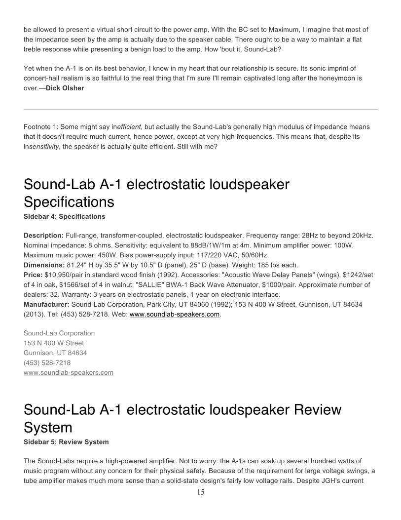
To investigate the answer to Dick's question, I measured the A-1's impedance magnitude at three settings of the Brilliance Control (BC) with DRA Labs' MLSSA system. With the BC set at Maximum (pot wide open), I obtained the curves in fig.1. Although the magnitude of the impedance is above 10 ohms from the upper bass to 2kHz, and well above 30 ohms in the bass, note the drop in the mid-treble and above. The cursor indicates a punishingly low 1.3 ohms at 20kHz with an equally punishing phase angle of –75.5°, dropping even further to just a small fraction of an ohm at ultrasonic frequencies. This measurement necessarily includes the resistance of the speaker cables DO was using (TARA Labs Rectangular Solid Core); as the margin of error in my measurement is probably around a fraction of ohm, it's quite possible that the A-1 presents amplifiers with a complete short circuit above the audio range. Fundamentally, therefore, in electrical terms, the A-1 with its BC set to maximum is nothing more than a large capacitor. If this isn't hell for a power amplifier, I don't know what is (footnote 1). No wonder DO's amps were choking.
17
Fig.1 Sound-Lab A-1, electrical impedance (solid) and phase (dashed) (2 ohms/vertical div.).
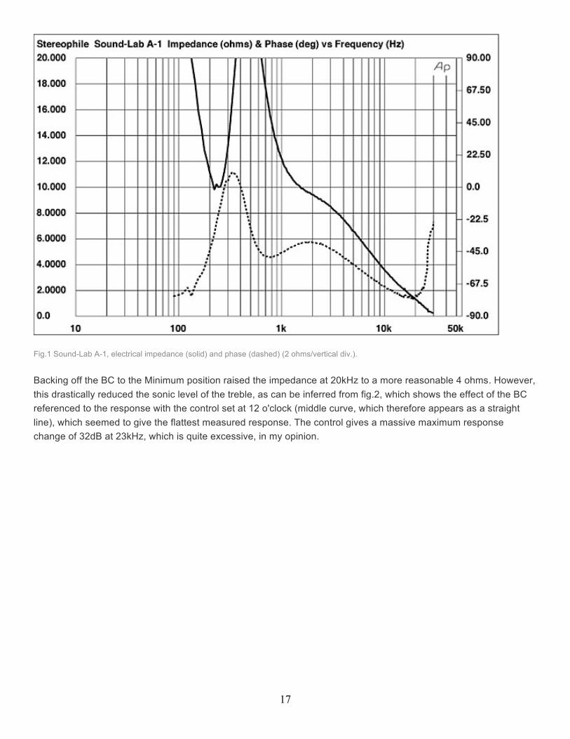
Backing off the BC to the Minimum position raised the impedance at 20kHz to a more reasonable 4 ohms. However, this drastically reduced the sonic level of the treble, as can be inferred from fig.2, which shows the effect of the BC referenced to the response with the control set at 12 o'clock (middle curve, which therefore appears as a straight line), which seemed to give the flattest measured response. The control gives a massive maximum response change of 32dB at 23kHz, which is quite excessive, in my opinion.
18
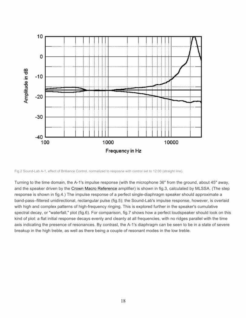
Fig.2 Sound-Lab A-1, effect of Brilliance Control, normalized to resposne with control set to 12:00 (straight line).
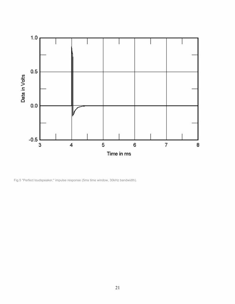
Turning to the time domain, the A-1's impulse response (with the microphone 36" from the ground, about 45" away, and the speaker driven by the Crown Macro Reference amplifier) is shown in fig.3, calculated by MLSSA. (The step response is shown in fig.4.) The impulse response of a perfect single-diaphragm speaker should approximate a band-pass–filtered unidirectional, rectangular pulse (fig.5); the Sound-Lab's impulse response, however, is overlaid with high and complex patterns of high-frequency ringing. This is explored further in the speaker's cumulative spectral decay, or "waterfall," plot (fig.6). For comparison, fig.7 shows how a perfect loudspeaker should look on this kind of plot: a flat initial response decays evenly and cleanly at all frequencies, with no ridges parallel with the time axis indicating the presence of resonances. By contrast, the A-1's diaphragm can be seen to be in a state of severe breakup in the high treble, as well as there being a couple of resonant modes in the low treble.

19
Fig.3 Sound-Lab A-1, impulse response at 45" with mike 36" from floor (5ms time window, 30kHz bandwidth).

20
Fig.4 Sound-Lab A-1, step response at 45" with mike 36" from floor (5ms time window, 30kHz bandwidth).
21
Fig.5 "Perfect loudspeaker," impulse response (5ms time window, 30kHz bandwidth).
22
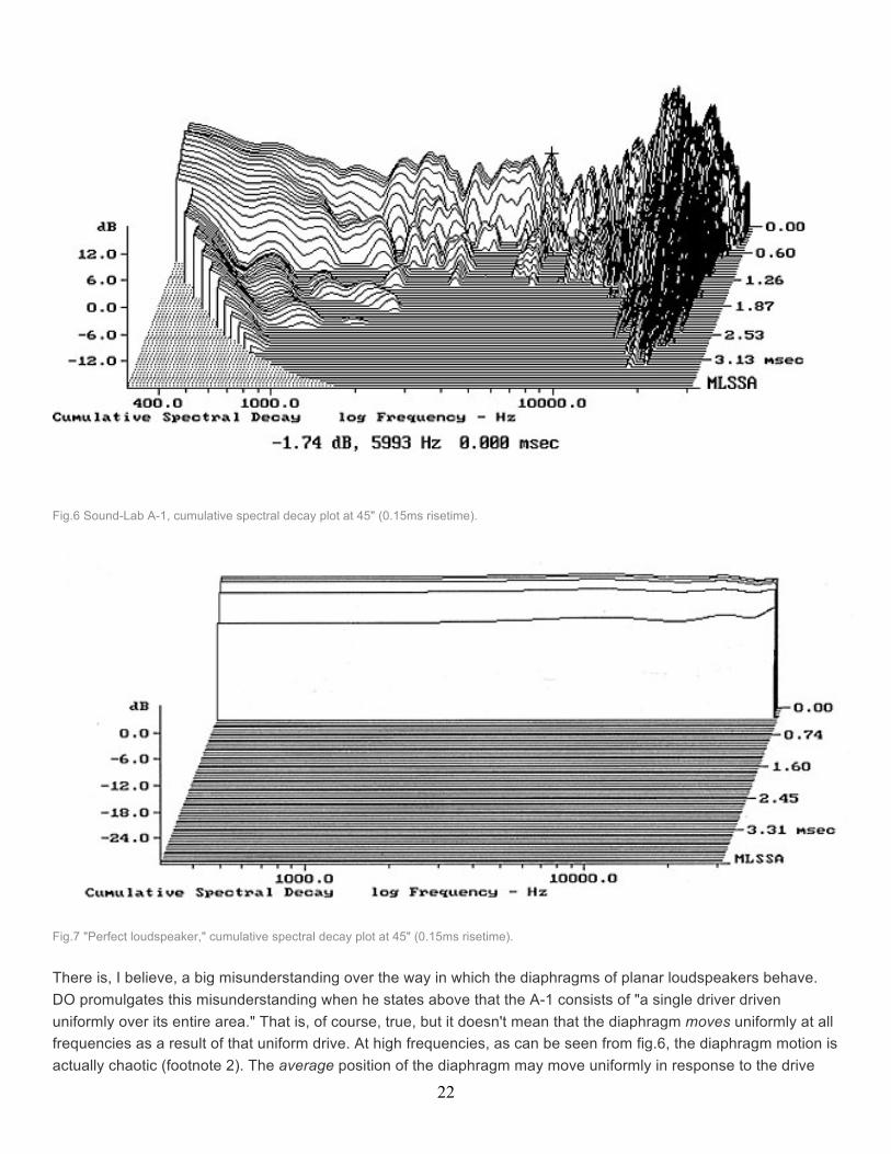
Fig.6 Sound-Lab A-1, cumulative spectral decay plot at 45" (0.15ms risetime).
Fig.7 "Perfect loudspeaker," cumulative spectral decay plot at 45" (0.15ms risetime).
There is, I believe, a big misunderstanding over the way in which the diaphragms of planar loudspeakers behave. DO promulgates this misunderstanding when he states above that the A-1 consists of "a single driver driven uniformly over its entire area." That is, of course, true, but it doesn't mean that the diaphragm moves uniformly at all frequencies as a result of that uniform drive. At high frequencies, as can be seen from fig.6, the diaphragm motion is actually chaotic (footnote 2). The average position of the diaphragm may move uniformly in response to the drive
23
signal, but each little element of the diaphragm "shivers" about that average position, with perhaps one element in front of where it should be but its immediate neighbor behind. The trick for the speaker designer is to push this chaotic behavior high enough in frequency that it doesn't intrude on the music. From my own auditioning of the A-1s, I believe Dr. West has managed to do this. The worst behavior in fig.6, for example, is above 15kHz, where the ear's sensitivity falls off rapidly.
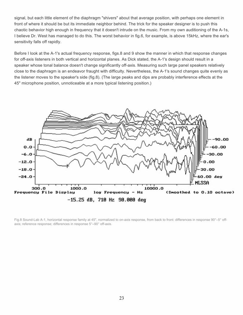
Before I look at the A-1's actual frequency response, figs.8 and 9 show the manner in which that response changes for off-axis listeners in both vertical and horizontal planes. As Dick stated, the A-1's design should result in a speaker whose tonal balance doesn't change significantly off-axis. Measuring such large panel speakers relatively close to the diaphragm is an endeavor fraught with difficulty. Nevertheless, the A-1's sound changes quite evenly as the listener moves to the speaker's side (fig.8). (The large peaks and dips are probably interference effects at the 45" microphone position, unnoticeable at a more typical listening position.)
Fig.8 Sound-Lab A-1, horizontal response family at 45", normalized to on-axis response, from back to front: differences in response 90°–5° off-axis; reference response; differences in response 5°–90° off-axis.
24
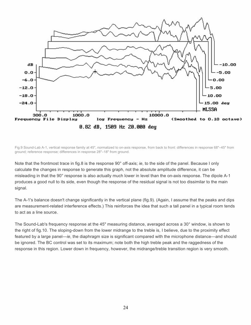
Fig.9 Sound-Lab A-1, vertical response family at 45", normalized to on-axis response, from back to front: differences in response 68"–45" from ground; reference response; differences in response 28"–18" from ground.
Note that the frontmost trace in fig.8 is the response 90° off-axis; ie, to the side of the panel. Because I only calculate the changes in response to generate this graph, not the absolute amplitude difference, it can be misleading in that the 90° response is also actually much lower in level than the on-axis response. The dipole A-1 produces a good null to its side, even though the response of the residual signal is not too dissimilar to the main signal.
The A-1's balance doesn't change significantly in the vertical plane (fig.9). (Again, I assume that the peaks and dips are measurement-related interference effects.) This reinforces the idea that such a tall panel in a typical room tends to act as a line source.
The Sound-Lab's frequency response at the 45" measuring distance, averaged across a 30° window, is shown to the right of fig.10. The sloping-down from the lower midrange to the treble is, I believe, due to the proximity effect featured by a large panel—ie, the diaphragm size is significant compared with the microphone distance—and should be ignored. The BC control was set to its maximum; note both the high treble peak and the raggedness of the response in this region. Lower down in frequency, however, the midrange/treble transition region is very smooth.
25
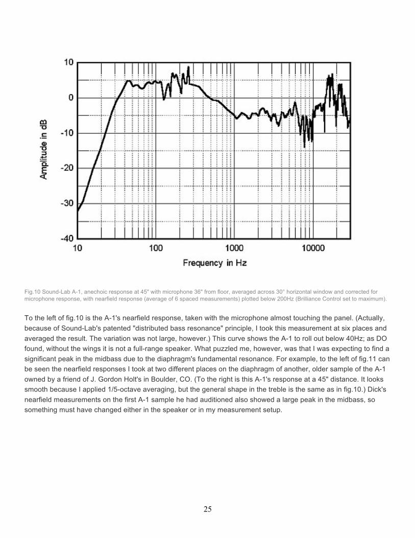
Fig.10 Sound-Lab A-1, anechoic response at 45" with microphone 36" from floor, averaged across 30° horizontal window and corrected for microphone response, with nearfield response (average of 6 spaced measurements) plotted below 200Hz (Brilliance Control set to maximum).
To the left of fig.10 is the A-1's nearfield response, taken with the microphone almost touching the panel. (Actually, because of Sound-Lab's patented "distributed bass resonance" principle, I took this measurement at six places and averaged the result. The variation was not large, however.) This curve shows the A-1 to roll out below 40Hz; as DO found, without the wings it is not a full-range speaker. What puzzled me, however, was that I was expecting to find a significant peak in the midbass due to the diaphragm's fundamental resonance. For example, to the left of fig.11 can be seen the nearfield responses I took at two different places on the diaphragm of another, older sample of the A-1 owned by a friend of J. Gordon Holt's in Boulder, CO. (To the right is this A-1's response at a 45" distance. It looks smooth because I applied 1/5-octave averaging, but the general shape in the treble is the same as in fig.10.) Dick's nearfield measurements on the first A-1 sample he had auditioned also showed a large peak in the midbass, so something must have changed either in the speaker or in my measurement setup.

26
Fig.11 Sound-Lab A-1, Colorado sample, 1/5 octave-smoothed anechoic response averaged across 30° horizontal window and corrected for microphone response, with 2 separate nearfield responses plotted below 200Hz.
I was puzzled enough by this result that I went back and remeasured the nearfield low-frequency response of the Wilson Puppy I'd last measured in April 1991. Within a dB here and there, the old and new curves matched, indicating that the B&K 4006 microphone/EAR mike preamplifier I use had not changed in the meantime. Presumably, therefore, this latest sample of the A-1 is behaving in a manner different from that of older versions. (The SALLIE—see later—was in place for these measurements.) Certainly, from my own auditioning, the speaker didn't sound as if it had a peak in the bass, the sound being tight and clean, whereas the Colorado sample did.
I mentioned earlier that I was unable to measure the A-1 when driven by DO's preferred OTL tube amplifier, the Fourier Sans Pareil. As Tom Norton had measured the Fourier's output impedance to accompany the review last June, it was a simple matter to calculate the effect on the A-1's frequency response that would result from the interaction between the speaker's modulus of impedance and the amplifier's relatively high source impedance, which ranges from 0.37 ohms at 1kHz to 0.55 ohms at 20kHz. Fig.12 shows the response between 200Hz and 20kHz from fig.10, but modified with this interaction. Because the speaker's impedance rises to tens of ohms below 200Hz, using the Fourier will boost the bass. In the treble, however, where the speaker's impedance is falling, the response will be increasingly tilted down with the tube amp, with at least a 3dB attenuation at 20kHz, as shown in fig.12.

27
Fig.12 Sound-Lab A-1, anechoic response above 200Hz from fig. 10, corrected for microphone response and adjusted for interaction between speaker impedance in fig.1 and measured output impedance of Fourier OTL amplifier.
Certainly I found the A-1 driven by the Fourier to offer an extremely natural midrange and treble tonality, with only occasionally a hint of very-high-frequency tizz. But I have to reinforce DO's comments on the A-1's soundstaging, something that will not be revealed by these measurements. The impression of image size was extremely lifelike, much more so than I have experienced from conventional dynamic speakers or even from smaller panel speakers like the Quads.
Finally, figs.13 and 14 show the effect of the wings on the speaker's response, taken by DO at the listening seat. Dick notes that "there is a common conception that an omni mike positioned at the location of the listener's head, together with a swept sinewave response, can be used to accurately predict the perceived sound field. That's just not so.

28
Fig.13 Sound-Lab A-1, in-room response at DO's listening seat without wings (midrange/bass balance set to –6/+3dB, Brilliance Control set to maximum).
Fig.14 Sound-Lab A-1, in-room response at DO's listening seat with wings (midrange/bass balance set to –6/+3dB, Brilliance Control set to maximum).
"There are at least two major problems with such an approach. While an omni's acceptance pattern does not discriminate against any particular angle of incidence, the pinna and ear canal most definitely do. To quote Jens Blauert, the noted German psychoacoustician: 'The pinna, along with the ear canal, forms a system of acoustical resonators. The degree to which individual resonances of this system are excited depends on the direction and distance of the sound source.' In my experience, the response of a mike with a cardioid pickup pattern correlates more closely with listening impressions.
"Second, there's a problem in using steady-state signals (ie, sinewaves) to measure bass response in a room. Unlike bass transients—which do not fully energize room standing waves—sinewaves build up room modes to their fullest. Thus, a room's resonant signature is more apparent with sinewaves than it is with music signal. Using a warble tone, as I do, to minimize the buildup of room modes, helps in this regard."
With these caveats in mind, fig.13 shows the listening position response with the A-1s' EQ set to –6/+3dB, which DO found to yield the most convincing tonal balance in his room. Ignore the deep dip at 38Hz, which will be due to a specific node at the mike position chosen by DO. With the reinforcement offered by the room, the bass is already

29
quite extended; adding the wings pushes the in-room extension to 20Hz (fig.14), which is why DO decided to try again with them.—John Atkinson
Footnote 1: I had wanted to drive the speaker with Dick's preferred Fourier OTL for these measurements. However, even at RMS levels of 1–4W, the output tube plates glowed cherry red with the low peak:mean ratio MLS signal, and the amp shut down.
Footnote 2: That this motion is mathematically chaotic is revealed by the fact that panel speakers tend to produce subharmonics when driven hard. (The mathematician Manfred Schroeder has said that the production of subharmonics is always an indication of chaotic behavior.) SeeStereophile, May 1992, p.109, for example, where I showed the spectrum of a panel speaker reproducing a 1kHz tone at a high level. As well as conventional distortion harmonics that are higher in frequency than the fundamental, the spectrum shows a significant amount of 500Hz being produced by the diaphragm.