sound transmit ion in movable partitions
TRANSCRIPT
8/4/2019 Sound Transmit Ion in Movable Partitions
http://slidepdf.com/reader/full/sound-transmit-ion-in-movable-partitions 1/10
Sound Transmission Loss of Movable Double-leaf
Partition Wall
Jian Chena, Jian Wang
a,1andGerard Muckian
b
aSchool of Mechanical and Aerospace Engineering, Queen’s University Belfast,
Ashby Building, Stranmillis Road, Belfast BT9 5AH, Northern Ireland, UK b
Master’s Choice Ltd. Silverbridge, Newry,BT35 9LJ, Northern Ireland, UK
Abstract: In this paper, the laboratory tests of Sound Transmission Loss (STL) of movable
double-leaf partition walls are present. Three sets of sample partition walls, with different
configuration, are employed; and all tests were carried out under the guidance of ISO140-1and 3 standards. The results shown that bigger air gap, increase frame’s damping and
reducing frame’s stiffness are benefit to the improvement in walls’ acoustic performance. It
was also demonstrated that if movable partition walls are mounted in similar manors to the
actual construction in laboratory tests, their STL are much worse than that of the counterpart
drywalls.
Keywords: sound transmission loss, movable partition wall, laboratory test.
1 Introduction
Movable partition walls are broadly used in construction industry for room’ssubdivision. This kind of partitions enjoys the merit of flexible setting for its
lightweight characteristic. They share the similiar double-leaf configuration tofixed partition drywalls. Like all lightweight walls, the sound insulation level of movable partition walls is an important factor that needs to be taken into account
during their application. The existing research has studied the sound performanceof double-leaf configuration and Sound Transmission Loss (STL) of drywalls.
Sharp [1] developed an empirical method for predicting the STL of double panel by analyzing the power radiated from a point-or line-loaded panel. Mead andPujara [2] proposed to use space-harmonic expansions to study periodic partitions;they set up a two-dimensional model in which the panel is represented as a beamsupported by regularly spaced elastic supports. The experimental sound insulationdata for different partition configuration has been showed in J.Q.Wang’s work [3].The carefully planned experimental parametric study present by Hongisto et al. [4]also strengthens the understanding of double panel’s acoustic performance. Wang
1Corresponding Author Email : [email protected]
8/4/2019 Sound Transmit Ion in Movable Partitions
http://slidepdf.com/reader/full/sound-transmit-ion-in-movable-partitions 2/10
J. Chen, J. Wang and G. Muckian164
et al. [5] studied the smeared and periodic model for sound transmission across the partition walls, and the predictions of the two models are compared on the basis of
practical testing results. Most of the research is based on fixed partition walls’
experiments. In this paper, the laboratory sound transmission tests on three sets of movable partition walls were conducted. Owning to the differences inconfiguration, the experiment results proved that air gap and frame’s stiffness and
damping influence the moveable partition walls’ STL. Meanwhile, compared to previous research on fixed partition walls, it was also concluded that the moveable
partition walls’ acoustic performance is confined by the installation ways adoptedin the tests.
2 Prediction of sound transmission loss
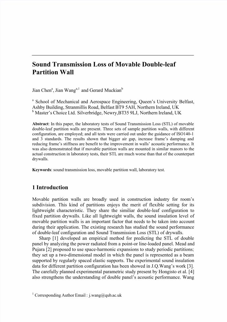
The theories present here are only for purpose of estimating the various inmoveable partition wall’s STL than the absolutes values. Previous work [5] has putforwards a periodic model of the sound transmission loss through double-leaf lightweight partitions stiffened with periodically placed studs. In this model, the panels on two sides are assumed infinitive large and stiffened in one direction bystuds which is simplified as translational and rotational springs with two pieces of lumped mass attached to the two panels respectively. The STL of double-leaf
partition can be predicted by the following route.
Figure 1. Side view of double-leaf partition wall with studs
The panel transverse displacement Wi (x, t) and the velocity potential
(1, 2, 3) in the incident, cavity and transmitted areas (Fig. 1) can be presented as
n
t j x Lnk jn eet xW x
2
,1),(1
(1a)
n
t j x Lnk jn eet xW x
2
,2),(2
(1b)
t yk x Ln j
n
t yk x L j yn y e Iet y x
2
10,,
(2a)
8/4/2019 Sound Transmit Ion in Movable Partitions
http://slidepdf.com/reader/full/sound-transmit-ion-in-movable-partitions 3/10
Sound Transmission Loss of Movable Double-leaf Partition Wall 165
n
t yk x Ln j
nn
t yk x Ln j
n yn yn eet y x
22
2 ,, (2b)
n
t yk x Ln j
n ynet y x
2
3 ,,
( (2c)
where t xW i , is the panel transverse displacement, the coefficient ni, can be
considered as the travelling wave amplitude of the structure, L is the spacing
between studs, is the angular frequency, k x is the component of the wave number in the x direction (Fig. 1). With reference to Fig. 2, one has:
sink k x (3)
cosk k y
(4)
where ck / is the wave number of the incident plane wave. ynk
is the wave number in the y direction, which can be calculated from the
following formula [6,7] :
222 Lnk ck x yn
(5)
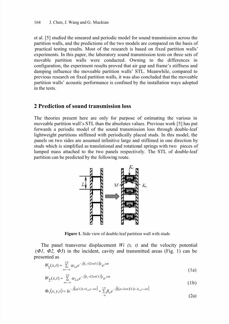
Figure 2. One periodic element and notation
When Lnk c x 2 the corresponding pressure waves become evanescent, and
the appropriate sign convention is to then replace y jk yn in the exponent of equation
(2a) by y yn
, where 22
2 c Lnk x yn
Corresponding changes are made to equation (2b) and (2c). 1 , 2 and 3 represent the velocity potentials in incident, cavity and transmitted areas
respectively. The coefficients n , n , n and n may be considered as the
travelling waves amplitudes of the incident (to the bottom panel), reflected andtransmitted waves, which are coupled with the motions of the two panels.
The coefficients ni,
can be found by solving the linear equation systemderived using the principle of virtual work for one bay of the partition (Fig. 1)
[6,7] shown below:

8/4/2019 Sound Transmit Ion in Movable Partitions
http://slidepdf.com/reader/full/sound-transmit-ion-in-movable-partitions 4/10
166 J. Chen, J. Wang and G. Muckian
02102
12
14
14
1 jt W m xW D p (6) 0320
22
22
42
42 jt W m xW D p (7)
where Di is the flexural stiffness of the panel and mpi is the mass per unit area of panels.
Following the procedures proposed in[5], the power transmission coefficient is:
2
00 2 I k I yi ( 8 )
where i I and t I are the incident and transmitted normal intensities, respectively,
given by [6,7]:
2
00 2 I k I yi (9a)
n ynnt k I Re2
2
0 (9b)
Substitution of (8) and (9) into the following equation (10) and (11) completes the
calculation of the STL, RL , across a double-leaf partition.The transmission coefficient averaged over all angles of incidence is:
/2
00
cossincossinlim
d d
(10)from which the transmission loss is calculated as:
10log10
RL (11)
3 Experimental arrangement and measurements
Three sets of movable partition walls were tested. Each sample consists of three panels and there are two categories in the panel’s thickness: 110mm and 150mm.One of the 110mm samples and the 150mm sample are composed of threestandard panels; for simplicity, we will called them 110 standard and 150 standardrespectively in the following sections. Another 110mm sample is composed of
two standard panels and one final panel with a telescoping panel mounted inside,and this sample will be named as 110 plus in the following sections. All panelsare supported by aluminium frames in flank, which play the same function asaforementioned partition walls’ studs. Specially, the aluminum frames of 150standard panels are divided in the place of central line and riveted again via a
connecting aluminium strip, and the rubbers are set at the connection points; thisdesign leads to less configuration stiffness coefficient and better dampingcharacteristic(see Fig 3).
8/4/2019 Sound Transmit Ion in Movable Partitions
http://slidepdf.com/reader/full/sound-transmit-ion-in-movable-partitions 5/10
Sound Transmission Loss of Movable Double-leaf Partition Wall 167
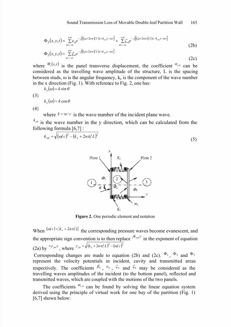
Figure 3. the configuration of 150 standard panels
For the standard panels, there is a layer of 15mm MDF boards as the outside
facing on both sides of the panels, and the boards are screwed with aluminiumframe in flank. A layer of 9.5mm gypsum boards are screwed on each inside of
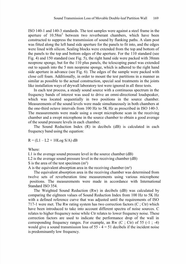
the MDF boards. Inside faces of both sides of gypsum boards are covered by alayer of 2.5mm polymeric acoustic pad. A jack is located in the centre of the panels to allow the extension of the sealing blocks top and bottom. Five wooden beams are periodically screwed on one side combined board (MDF + gypsum board + acoustic pad) to support the mechanical extending rods and, to someextend, horizontally strengthen the aluminium frames in spite of just a touch between them. Two layers of 25mm mineral wool are filled into the cavity of 150mm thick panels (see Fig. 3); but for 110mm thick panel, only one layer of
50mm mineral wool is packed inside. The differences in their configuration canalso be seen in Fig. 3 to 5.
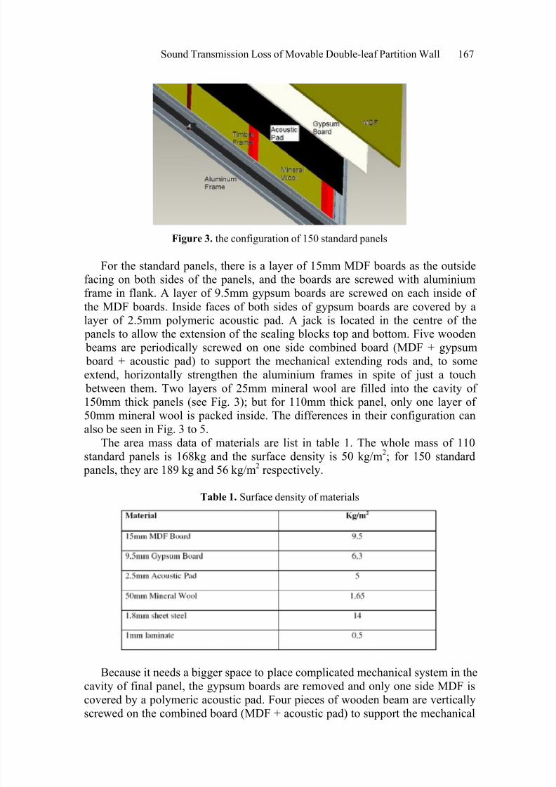
The area mass data of materials are list in table 1. The whole mass of 110standard panels is 168kg and the surface density is 50 kg/m
2; for 150 standard
panels, they are 189 kg and 56 kg/m2
respectively.
Table 1. Surface density of materials
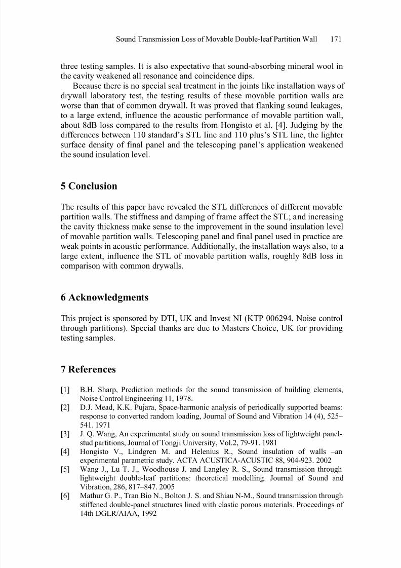
Because it needs a bigger space to place complicated mechanical system in the
cavity of final panel, the gypsum boards are removed and only one side MDF iscovered by a polymeric acoustic pad. Four pieces of wooden beam are verticallyscrewed on the combined board (MDF + acoustic pad) to support the mechanical
8/4/2019 Sound Transmit Ion in Movable Partitions
http://slidepdf.com/reader/full/sound-transmit-ion-in-movable-partitions 6/10
168 J. Chen, J. Wang and G. Muckian
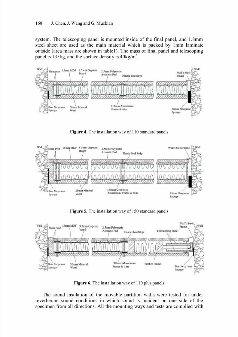
system. The telescoping panel is mounted inside of the final panel, and 1.8mmsteel sheet are used as the main material which is packed by 1mm laminate
outside (area mass are shown in table1). The mass of final panel and telescoping
panel is 135kg, and the surface density is 40kg/m
2
.
Figure 4. The installation way of 110 standard panels
Figure 5. The installation way of 150 standard panels
Figure 6. The installation way of 110 plus panels
The sound insulation of the movable partition walls were tested for under reverberant sound conditions in which sound is incident on one side of thespecimen from all directions. All the mounting ways and tests are complied with
8/4/2019 Sound Transmit Ion in Movable Partitions
http://slidepdf.com/reader/full/sound-transmit-ion-in-movable-partitions 7/10
Sound Transmission Loss of Movable Double-leaf Partition Wall 169
ISO 140-1 and 140-3 standards. The test samples were against a steel frame in theaperture of 10.58m2 between two reverberant chambers, which have been
constructed to suppress the transmission of sound by flanking paths. A slam post
was fitted along the left hand side aperture for the panels to fit into, and the edgeswere lined with silicon. Sealing blocks were extended from the top and bottom of the panels to the top and bottom edges of the aperture. For the 110 standard (see
Fig. 4) and 150 standard (see Fig. 5), the right hand side were packed with 38mmneoprene sponge, but for the 110 plus panels, the telescoping panel was extended
out to squash into the 5 mm neoprene sponge, which is adhered to the right handside aperture in advance (see Fig. 6). The edges of the sample were packed withclose cell foam. Additionally, in order to mount the test partitions in a manner assimilar as possible to the actual construction, special seal treatments in the joints
like installation ways of drywall laboratory test were ignored in all three tests.In each test process, a steady sound source with a continuous spectrum in the
frequency bands of interest was used to drive an omni-directional loudspeaker,which was located sequentially in two positions in the source chamber.Measurements of the sound levels were made simultaneously in both chambers atthe one-third octave intervals from 100 Hz to 5K Hz as prescribed in ISO 140-3.The measurements were made using a swept microphone scan in the receivingchamber and a swept microphone in the source chamber to obtain a good averageof the sound pressure levels in each chamber.
The Sound Reduction Index (R) in decibels (dB) is calculated in eachfrequency band using the equation:
R = (L1 – L2 + 10Log S/A) dB
Where:L1 is the average sound pressure level in the source chamber (dB)L2 is the average sound pressure level in the receiving chamber (dB)S is the area of the test specimen (m²)
A is the equivalent absorption area in the receiving chamber (m²)The equivalent absorption area in the receiving chamber was determined from
twelve sets of reverberation time measurements using various microphone positions. The measurements were made in accordance with International
Standard ISO 354.The Weighted Sound Reduction (Rw) in decibels (dB) was calculated by
comparing the eighteen values of Sound Reduction Index from 100 Hz to 5K Hzwith a defined reference curve that was adjusted until the requirements of ISO717-1 were met. The Rw rating system has two correction factors (C ; Ctr) whichhave been introduced to take into account different spectra of noise sources. Crelates to higher frequency noise while Ctr relates to lower frequency noise. Thesecorrection factors are used to indicate the performance drop of the wall incorresponding frequency ranges. For example, an Rw (C ; Ctr) of 55 (-1 ; -4)would give a sound transmission loss of 55 - 4 = 51 decibels if the incident noise
is predominantly low frequency.

8/4/2019 Sound Transmit Ion in Movable Partitions
http://slidepdf.com/reader/full/sound-transmit-ion-in-movable-partitions 8/10
170 J. Chen, J. Wang and G. Muckian
4 Result and discussion
Fig. 7 shows the testing results of three sets of partition walls. The weighted
sound reduction data for the 150 standard panels, 110 standard panels and 110 plus panels are 39dB, 36dB and 35dB respectively. It is obvious that 150 standard panels have better sound insulation level than other two kinds. The STL line of 150 standard panels shows that there are only small fluctuations responding to the
frequency
Figure 7. Test results
band from 100Hz to 2000Hz, approximately 1-2dB increase per octave; but after 2000Hz, the STL line increase strongly, about 7dB per octave. The 110 standard panels’ STL line exhibits more apparent fluctuations; from 100HZ to 160Hz,there is a more than 10dB increase; but after that, the STL index go down againstthe frequency increase, reaching the rock bottom at 500Hz; then the STL lineenters a smooth raise section at the rate of 3-5dB per octave. For the 110 plus
panels, the increases in STL index are also obvious in the low frequency band;from 400Hz to 2000Hz, the fluctuation phenomena presents some small increases,accompanied by a couple of little drops; the increase rate from 2000Hz to 4000Hzis about 4dB per octave.
The complex aluminium frames of 150 standard panels enjoy lower structure
stiffness and bigger damping coefficient. It is worth noting that the cavity of 150standard panels is thicker than these of other two kinds. Therefore it is expectablethat the 150 standard panels have best sound insulation level, which is in line withthe acoustic performance rule of double-leaf partition. According to Sharp’sconclusion[8], the slope of the STL with uncoupled double wall is 18dB/octave
above the lowest mass-air-mass resonance frequency f 0; Hongisto et al. [4]experiment results also shown that there is approximately 10dB/octave increaseabove f 0 for the coupled double leaf wall. But this characteristic is not clear for all
8/4/2019 Sound Transmit Ion in Movable Partitions
http://slidepdf.com/reader/full/sound-transmit-ion-in-movable-partitions 9/10
Sound Transmission Loss of Movable Double-leaf Partition Wall 171
three testing samples. It is also expectative that sound-absorbing mineral wool inthe cavity weakened all resonance and coincidence dips.
Because there is no special seal treatment in the joints like installation ways of
drywall laboratory test, the testing results of these movable partition walls areworse than that of common drywall. It was proved that flanking sound leakages,to a large extend, influence the acoustic performance of movable partition wall,
about 8dB loss compared to the results from Hongisto et al. [4]. Judging by thedifferences between 110 standard’s STL line and 110 plus’s STL line, the lighter
surface density of final panel and the telescoping panel’s application weakenedthe sound insulation level.
5 Conclusion
The results of this paper have revealed the STL differences of different movable partition walls. The stiffness and damping of frame affect the STL; and increasingthe cavity thickness make sense to the improvement in the sound insulation levelof movable partition walls. Telescoping panel and final panel used in practice areweak points in acoustic performance. Additionally, the installation ways also, to alarge extent, influence the STL of movable partition walls, roughly 8dB loss incomparison with common drywalls.
6 Acknowledgments
This project is sponsored by DTI, UK and Invest NI (KTP 006294, Noise controlthrough partitions). Special thanks are due to Masters Choice, UK for providingtesting samples.
7 References
[1] B.H. Sharp, Prediction methods for the sound transmission of building elements,
Noise Control Engineering 11, 1978.[2] D.J. Mead, K.K. Pujara, Space-harmonic analysis of periodically supported beams:
response to converted random loading, Journal of Sound and Vibration 14 (4), 525–
541. 1971
[3] J. Q. Wang, An experimental study on sound transmission loss of lightweight panel-
stud partitions, Journal of Tongji University, Vol.2, 79-91. 1981[4] Hongisto V., Lindgren M. and Helenius R., Sound insulation of walls –an
experimental parametric study. ACTA ACUSTICA-ACUSTIC 88, 904-923. 2002
[5] Wang J., Lu T. J., Woodhouse J. and Langley R. S., Sound transmission through
lightweight double-leaf partitions: theoretical modelling. Journal of Sound and
Vibration, 286, 817–847. 2005
[6]
Mathur G. P., Tran Bio N., Bolton J. S. and Shiau N-M., Sound transmission throughstiffened double-panel structures lined with elastic porous materials. Proceedings of
14th DGLR/AIAA, 1992

8/4/2019 Sound Transmit Ion in Movable Partitions
http://slidepdf.com/reader/full/sound-transmit-ion-in-movable-partitions 10/10
172 J. Chen, J. Wang and G. Muckian
[7] Lee J-H, Kim J., Analysis of sound transmission through periodically stiffened panels by space harmonic expansion method. Journal of Sound and Vibration 251:2,
349-366. 2002
[8] B. H. Sharp, A study of techniques to increase the sound insulation of building
elements. Wyle laboratories report WR73-5, El Segundo, California, USA, 1973.