sp pro - three phase installation notesdownload.selectronic.com.au/documents/installnotes... · sp...
TRANSCRIPT
IN0016 Revision 12 Part # 004573 – 1 of 22 POWER PERFORMANCE PASSION
SP PRO Three Phase Installation Notes
SP PRO - Three Phase Installation Notes For SP PRO Firmware revision 7.01 and above.
Contents
SP PRO - Three Phase Installation Notes ............................................................................... 1
Introduction ..................................................................................................................... 2
Installation checklist .......................................................................................................... 3
Wiring Overview ............................................................................................................... 6
Installation ..................................................................................................................... 10
Charge Stage Linking ................................................................................................... 13
SP PRO Configuration – Additional Configuration Settings .................................................. 13
System – Multiple Phase Settings ................................................................................. 13
Verifying Phase Settings ............................................................................................... 14
System – Multiple SP PRO Charging .............................................................................. 15
Charge Stage Linking ................................................................................................... 15
Test Linking (Test linking of charge stages) .................................................................. 16
Shunts ........................................................................................................................ 17
Zero all current shunts ................................................................................................. 18
Test shunt 1 ................................................................................................................ 18
SoC Control ................................................................................................................. 18
Battery Capacity .......................................................................................................... 18
Max. Charge Current .................................................................................................... 18
Battery Charger Voltage settings and Temperature Compensation .................................. 18
DC Shutdown and Generator Lock Out Override ............................................................ 19
Disable Generator Control on L2 and L3 ........................................................................ 19
AC Source Power ......................................................................................................... 20
Test System Function .................................................................................................. 20
Solar Hybrid Control .................................................................................................... 21
Synchronising SoC between inverters. .......................................................................... 22
Operation ....................................................................................................................... 22
Additional Information ..................................................................................................... 22
IN0016 Revision 12 Part # 004573 – 2 of 22
SP PRO Three Phase Installation Notes
POWER PERFORMANCE PASSION
Introduction
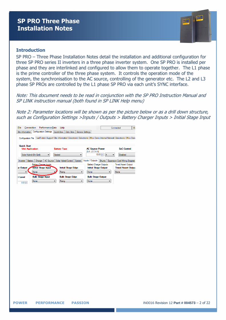
SP PRO – Three Phase Installation Notes detail the installation and additional configuration for three SP PRO series II inverters in a three phase inverter system. One SP PRO is installed per phase and they are interlinked and configured to allow them to operate together. The L1 phase is the prime controller of the three phase system. It controls the operation mode of the system, the synchronisation to the AC source, controlling of the generator etc. The L2 and L3 phase SP PROs are controlled by the L1 phase SP PRO via each unit’s SYNC interface. Note: This document needs to be read in conjunction with the SP PRO Instruction Manual and SP LINK instruction manual (both found in SP LINK Help menu) Note 2: Parameter locations will be shown as per the picture below or as a drill down structure, such as Configuration Settings >Inputs / Outputs > Battery Charger Inputs > Initial Stage Input
IN0016 Revision 12 Part # 004573 – 3 of 22 POWER PERFORMANCE PASSION
SP PRO Three Phase Installation Notes
Installation checklist
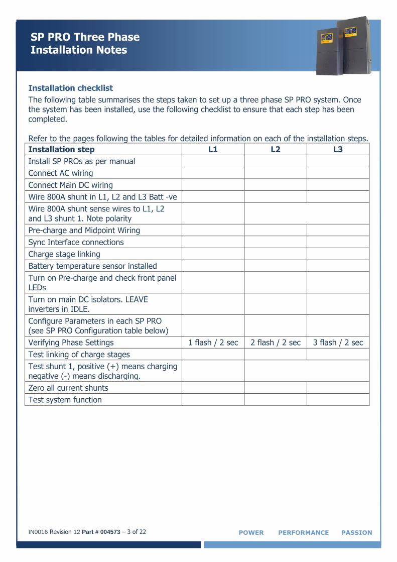
The following table summarises the steps taken to set up a three phase SP PRO system. Once the system has been installed, use the following checklist to ensure that each step has been completed. Refer to the pages following the tables for detailed information on each of the installation steps.
Installation step L1 L2 L3
Install SP PROs as per manual
Connect AC wiring
Connect Main DC wiring
Wire 800A shunt in L1, L2 and L3 Batt -ve
Wire 800A shunt sense wires to L1, L2 and L3 shunt 1. Note polarity
Pre-charge and Midpoint Wiring
Sync Interface connections
Charge stage linking
Battery temperature sensor installed
Turn on Pre-charge and check front panel LEDs
Turn on main DC isolators. LEAVE inverters in IDLE.
Configure Parameters in each SP PRO (see SP PRO Configuration table below)
Verifying Phase Settings 1 flash / 2 sec 2 flash / 2 sec 3 flash / 2 sec
Test linking of charge stages
Test shunt 1, positive (+) means charging negative (-) means discharging.
Zero all current shunts
Test system function
IN0016 Revision 12 Part # 004573 – 4 of 22
SP PRO Three Phase Installation Notes
POWER PERFORMANCE PASSION
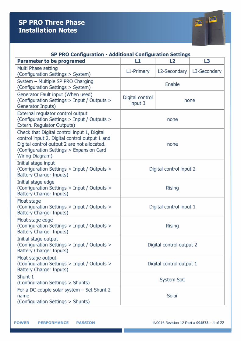
SP PRO Configuration - Additional Configuration Settings
Parameter to be programed L1 L2 L3
Multi Phase setting (Configuration Settings > System)
L1-Primary L2-Secondary L3-Secondary
System – Multiple SP PRO Charging (Configuration Settings > System)
Enable
Generator Fault input (When used) (Configuration Settings > Input / Outputs > Generator Inputs)
Digital control input 3
none
External regulator control output (Configuration Settings > Input / Outputs > Extern. Regulator Outputs)
none
Check that Digital control input 1, Digital control input 2, Digital control output 1 and Digital control output 2 are not allocated. (Configuration Settings > Expansion Card Wiring Diagram)
none
Initial stage input (Configuration Settings > Input / Outputs > Battery Charger Inputs)
Digital control input 2
Initial stage edge (Configuration Settings > Input / Outputs > Battery Charger Inputs)
Rising
Float stage (Configuration Settings > Input / Outputs > Battery Charger Inputs)
Digital control input 1
Float stage edge (Configuration Settings > Input / Outputs > Battery Charger Inputs)
Rising
Initial stage output (Configuration Settings > Input / Outputs > Battery Charger Inputs)
Digital control output 2
Float stage output (Configuration Settings > Input / Outputs > Battery Charger Inputs)
Digital control output 1
Shunt 1 (Configuration Settings > Shunts)
System SoC
For a DC couple solar system – Set Shunt 2 name (Configuration Settings > Shunts)
Solar
IN0016 Revision 12 Part # 004573 – 5 of 22 POWER PERFORMANCE PASSION
SP PRO Three Phase Installation Notes
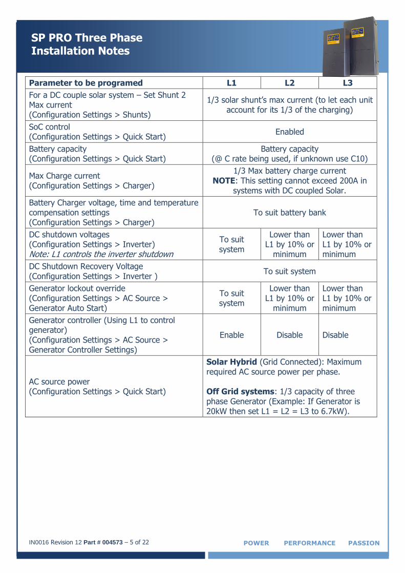
Parameter to be programed L1 L2 L3
For a DC couple solar system – Set Shunt 2 Max current (Configuration Settings > Shunts)
1/3 solar shunt’s max current (to let each unit account for its 1/3 of the charging)
SoC control (Configuration Settings > Quick Start)
Enabled
Battery capacity (Configuration Settings > Quick Start)
Battery capacity (@ C rate being used, if unknown use C10)
Max Charge current (Configuration Settings > Charger)
1/3 Max battery charge current NOTE: This setting cannot exceed 200A in
systems with DC coupled Solar.
Battery Charger voltage, time and temperature compensation settings (Configuration Settings > Charger)
To suit battery bank
DC shutdown voltages (Configuration Settings > Inverter) Note: L1 controls the inverter shutdown
To suit system
Lower than L1 by 10% or
minimum
Lower than L1 by 10% or minimum
DC Shutdown Recovery Voltage (Configuration Settings > Inverter )
To suit system
Generator lockout override (Configuration Settings > AC Source > Generator Auto Start)
To suit system
Lower than L1 by 10% or
minimum
Lower than L1 by 10% or minimum
Generator controller (Using L1 to control generator) (Configuration Settings > AC Source > Generator Controller Settings)
Enable Disable Disable
AC source power (Configuration Settings > Quick Start)
Solar Hybrid (Grid Connected): Maximum required AC source power per phase. Off Grid systems: 1/3 capacity of three phase Generator (Example: If Generator is 20kW then set L1 = L2 = L3 to 6.7kW).
IN0016 Revision 12 Part # 004573 – 6 of 22
SP PRO Three Phase Installation Notes
POWER PERFORMANCE PASSION
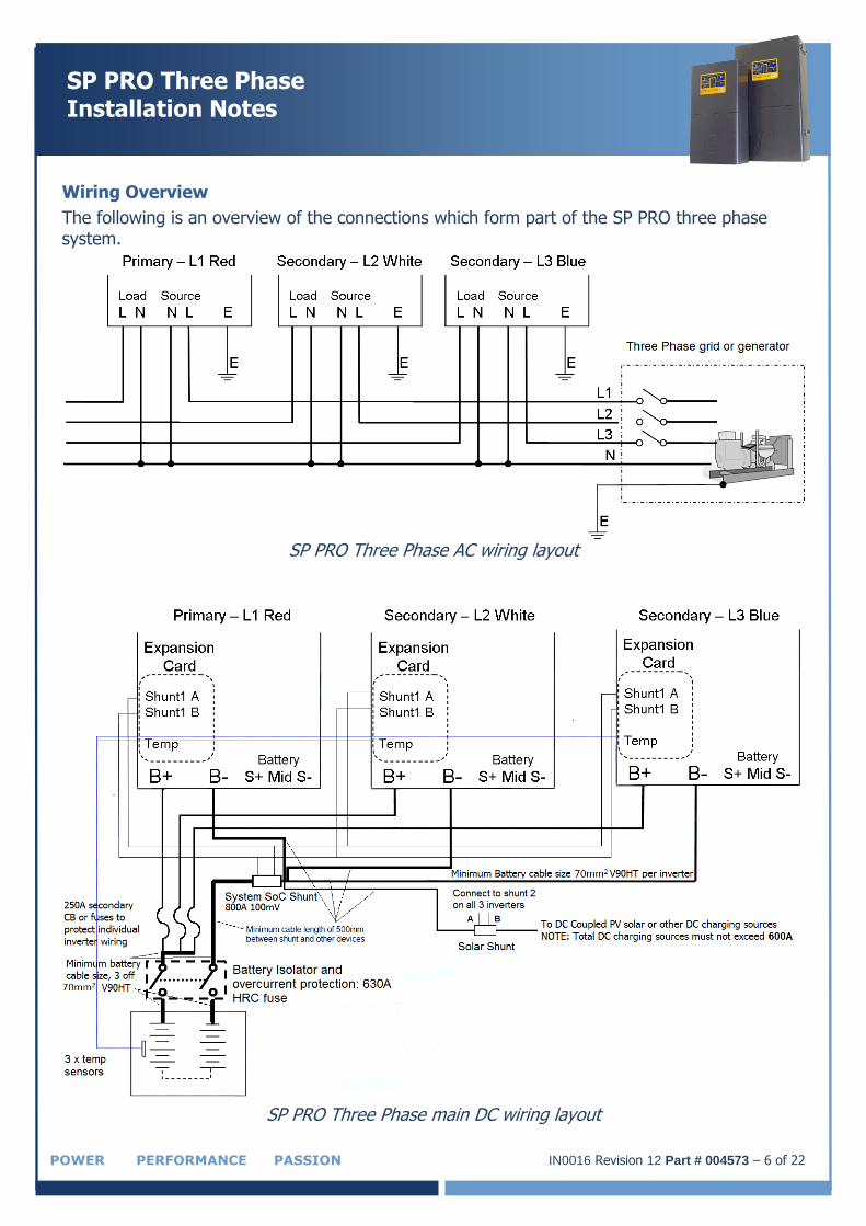
Wiring Overview
The following is an overview of the connections which form part of the SP PRO three phase system.
SP PRO Three Phase AC wiring layout
SP PRO Three Phase main DC wiring layout
IN0016 Revision 12 Part # 004573 – 7 of 22 POWER PERFORMANCE PASSION
SP PRO Three Phase Installation Notes
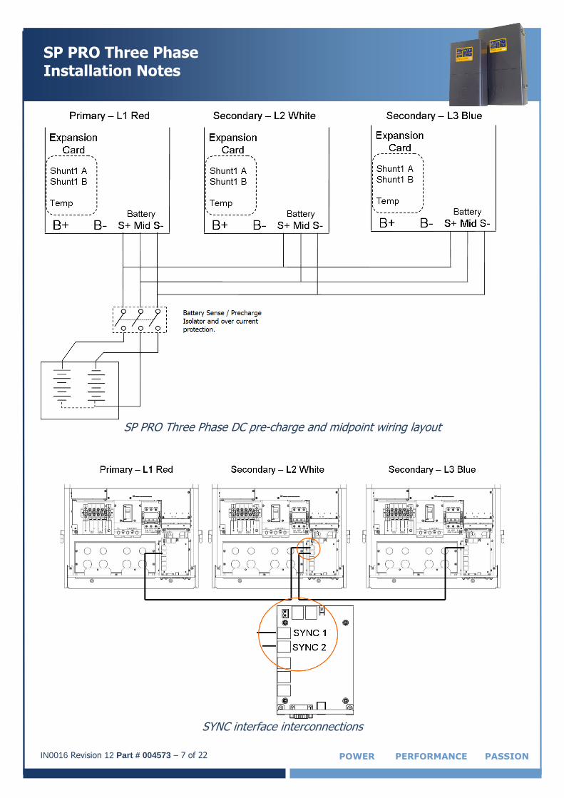
SP PRO Three Phase DC pre-charge and midpoint wiring layout
SYNC interface interconnections
IN0016 Revision 12 Part # 004573 – 8 of 22
SP PRO Three Phase Installation Notes
POWER PERFORMANCE PASSION
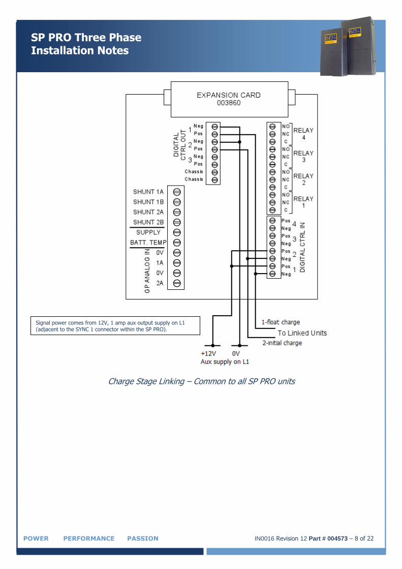
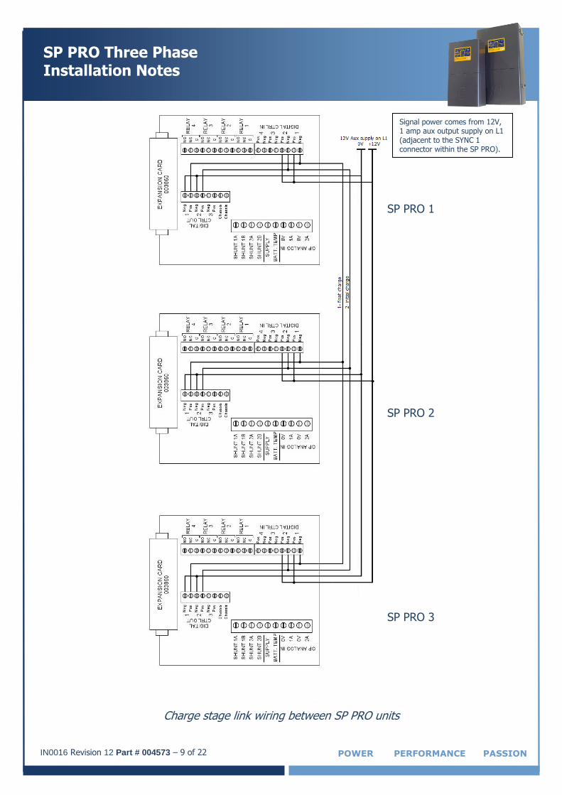
Charge Stage Linking – Common to all SP PRO units
Signal power comes from 12V, 1 amp aux output supply on L1 (adjacent to the SYNC 1 connector within the SP PRO).
IN0016 Revision 12 Part # 004573 – 9 of 22 POWER PERFORMANCE PASSION
SP PRO Three Phase Installation Notes
Charge stage link wiring between SP PRO units
SP PRO 3
SP PRO 2
SP PRO 1
Signal power comes from 12V, 1 amp aux output supply on L1 (adjacent to the SYNC 1 connector within the SP PRO).
IN0016 Revision 12 Part # 004573 – 10 of 22
SP PRO Three Phase Installation Notes
POWER PERFORMANCE PASSION
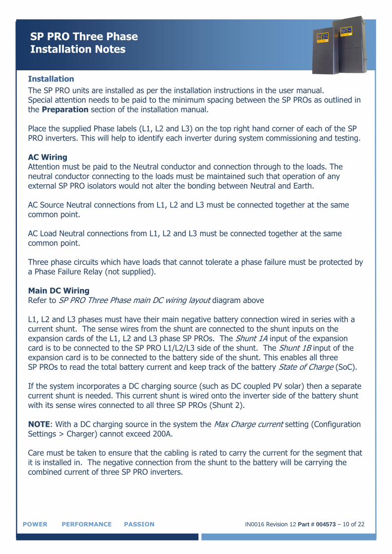
Installation
The SP PRO units are installed as per the installation instructions in the user manual. Special attention needs to be paid to the minimum spacing between the SP PROs as outlined in the Preparation section of the installation manual. Place the supplied Phase labels (L1, L2 and L3) on the top right hand corner of each of the SP PRO inverters. This will help to identify each inverter during system commissioning and testing. AC Wiring Attention must be paid to the Neutral conductor and connection through to the loads. The neutral conductor connecting to the loads must be maintained such that operation of any external SP PRO isolators would not alter the bonding between Neutral and Earth. AC Source Neutral connections from L1, L2 and L3 must be connected together at the same common point. AC Load Neutral connections from L1, L2 and L3 must be connected together at the same common point. Three phase circuits which have loads that cannot tolerate a phase failure must be protected by a Phase Failure Relay (not supplied). Main DC Wiring Refer to SP PRO Three Phase main DC wiring layout diagram above
L1, L2 and L3 phases must have their main negative battery connection wired in series with a current shunt. The sense wires from the shunt are connected to the shunt inputs on the expansion cards of the L1, L2 and L3 phase SP PROs. The Shunt 1A input of the expansion card is to be connected to the SP PRO L1/L2/L3 side of the shunt. The Shunt 1B input of the expansion card is to be connected to the battery side of the shunt. This enables all three SP PROs to read the total battery current and keep track of the battery State of Charge (SoC). If the system incorporates a DC charging source (such as DC coupled PV solar) then a separate current shunt is needed. This current shunt is wired onto the inverter side of the battery shunt with its sense wires connected to all three SP PROs (Shunt 2). NOTE: With a DC charging source in the system the Max Charge current setting (Configuration Settings > Charger) cannot exceed 200A. Care must be taken to ensure that the cabling is rated to carry the current for the segment that it is installed in. The negative connection from the shunt to the battery will be carrying the combined current of three SP PRO inverters.
IN0016 Revision 12 Part # 004573 – 11 of 22 POWER PERFORMANCE PASSION
SP PRO Three Phase Installation Notes
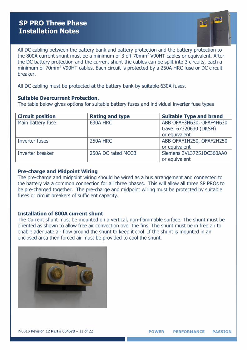
All DC cabling between the battery bank and battery protection and the battery protection to the 800A current shunt must be a minimum of 3 off 70mm2 V90HT cables or equivalent. After the DC battery protection and the current shunt the cables can be split into 3 circuits, each a minimum of 70mm2 V90HT cables. Each circuit is protected by a 250A HRC fuse or DC circuit breaker. All DC cabling must be protected at the battery bank by suitable 630A fuses. Suitable Overcurrent Protection. The table below gives options for suitable battery fuses and individual inverter fuse types
Circuit position Rating and type Suitable Type and brand
Main battery fuse 630A HRC ABB OFAF3H630, OFAF4H630 Gave: 67320630 (DKSH) or equivalent
Inverter fuses 250A HRC ABB OFAF1H250, OFAF2H250 or equivalent
Inverter breaker 250A DC rated MCCB Siemens 3VL37251DC360AA0 or equivalent
Pre-charge and Midpoint Wiring The pre-charge and midpoint wiring should be wired as a bus arrangement and connected to the battery via a common connection for all three phases. This will allow all three SP PROs to be pre-charged together. The pre-charge and midpoint wiring must be protected by suitable fuses or circuit breakers of sufficient capacity. Installation of 800A current shunt The Current shunt must be mounted on a vertical, non-flammable surface. The shunt must be oriented as shown to allow free air convection over the fins. The shunt must be in free air to enable adequate air flow around the shunt to keep it cool. If the shunt is mounted in an enclosed area then forced air must be provided to cool the shunt.
IN0016 Revision 12 Part # 004573 – 12 of 22
SP PRO Three Phase Installation Notes
POWER PERFORMANCE PASSION
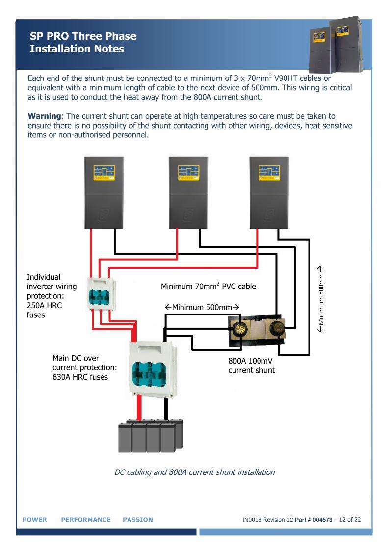
Each end of the shunt must be connected to a minimum of 3 x 70mm2 V90HT cables or equivalent with a minimum length of cable to the next device of 500mm. This wiring is critical as it is used to conduct the heat away from the 800A current shunt. Warning: The current shunt can operate at high temperatures so care must be taken to ensure there is no possibility of the shunt contacting with other wiring, devices, heat sensitive items or non-authorised personnel.
DC cabling and 800A current shunt installation
Main DC over current protection: 630A HRC fuses
Minimum 70mm2 PVC cable
800A 100mV current shunt
Individual inverter wiring protection: 250A HRC
fuses Minimum 500mm

IN0016 Revision 12 Part # 004573 – 13 of 22 POWER PERFORMANCE PASSION
SP PRO Three Phase Installation Notes
SYNC Interface Connections Each SP PRO must be interlinked via its SYNC interface. With reference to the diagram above (SYNC interface interconnections) connect each SP PRO together via either SYNC1 or SYNC 2 connection using the supplied “network” type cables. Only two cables are required to connect the three SP PRO units. Both SYNC1 and SYNC 2 connection points are the same and either can be used.
Charge Stage Linking
In order for the SP PROs units to share the charging of the battery bank, it is necessary for the charge stages to switch simultaneously. The charge stages are interconnected via wiring between each of the SP PROs Expansion cards. Each Expansion Card is wired in the same manner, then linked. Signal power comes from one of the SP PROs 12V 1 amp output supplies (adjacent to the SYNC 1 connector within the SP PRO).
SP PRO Configuration – Additional Configuration Settings
The following settings are required to activate the three phase mode on the three SP PRO inverters. It is good practise to start with the L1 Primary Phase as this will prevent false alarms on the L2 and L3 Secondary phases while loading the configurations. Turn on the pre-charge breaker or isolator for the system. When all three SP PRO inverters power up, turn on the main battery isolators for all three SP PRO inverters. NOTE: The SP PRO inverters may give “sync” errors until the main battery isolators have been closed on all three SP PRO inverters. LEAVE the SP PRO inverters in IDLE. All three phases must have their configuration programmed before attempting to start the system from Idle mode to On mode. It is required to create a separate SP LINK site file for each SP PRO phase and add the prefix “L1”, “L2” or “L3” to the appropriate file.
System – Multiple Phase Settings
Each SP PRO must be configured to suit the phase that is connected to by setting the Multi Phase setting (Configuration Settings > System)
L1 – Primary: SP PRO is set as L1 phase – Red Phase L2 – Secondary: SP PRO is set as L2 phase – White Phase L3 – Secondary: SP PRO is set as L3 phase – Blue Phase The Split Phase – Secondary and Disabled settings are not used in a three phase system.
IN0016 Revision 12 Part # 004573 – 14 of 22
SP PRO Three Phase Installation Notes
POWER PERFORMANCE PASSION
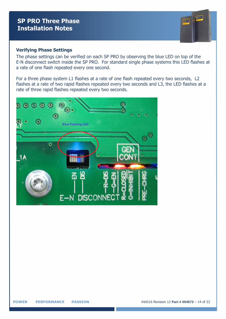
Verifying Phase Settings
The phase settings can be verified on each SP PRO by observing the blue LED on top of the E-N disconnect switch inside the SP PRO. For standard single phase systems this LED flashes at a rate of one flash repeated every one second. For a three phase system L1 flashes at a rate of one flash repeated every two seconds, L2 flashes at a rate of two rapid flashes repeated every two seconds and L3, the LED flashes at a rate of three rapid flashes repeated every two seconds.
IN0016 Revision 12 Part # 004573 – 15 of 22 POWER PERFORMANCE PASSION
SP PRO Three Phase Installation Notes
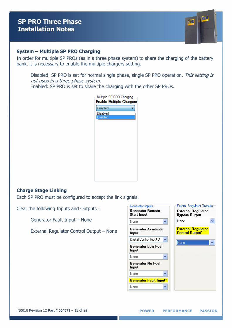
System – Multiple SP PRO Charging
In order for multiple SP PROs (as in a three phase system) to share the charging of the battery bank, it is necessary to enable the multiple chargers setting.
Disabled: SP PRO is set for normal single phase, single SP PRO operation. This setting is not used in a three phase system. Enabled: SP PRO is set to share the charging with the other SP PROs.
Charge Stage Linking
Each SP PRO must be configured to accept the link signals. Clear the following Inputs and Outputs :
Generator Fault Input – None
External Regulator Control Output – None
IN0016 Revision 12 Part # 004573 – 16 of 22
SP PRO Three Phase Installation Notes
POWER PERFORMANCE PASSION
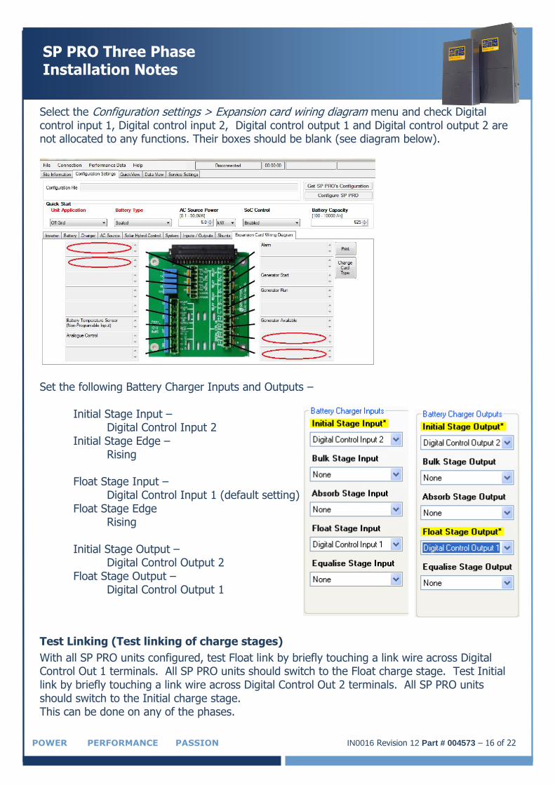
Select the Configuration settings > Expansion card wiring diagram menu and check Digital control input 1, Digital control input 2, Digital control output 1 and Digital control output 2 are not allocated to any functions. Their boxes should be blank (see diagram below).
Set the following Battery Charger Inputs and Outputs –
Initial Stage Input – Digital Control Input 2
Initial Stage Edge – Rising
Float Stage Input –
Digital Control Input 1 (default setting) Float Stage Edge
Rising
Initial Stage Output – Digital Control Output 2
Float Stage Output – Digital Control Output 1
Test Linking (Test linking of charge stages)
With all SP PRO units configured, test Float link by briefly touching a link wire across Digital Control Out 1 terminals. All SP PRO units should switch to the Float charge stage. Test Initial link by briefly touching a link wire across Digital Control Out 2 terminals. All SP PRO units should switch to the Initial charge stage. This can be done on any of the phases.
IN0016 Revision 12 Part # 004573 – 17 of 22 POWER PERFORMANCE PASSION
SP PRO Three Phase Installation Notes
Shunts
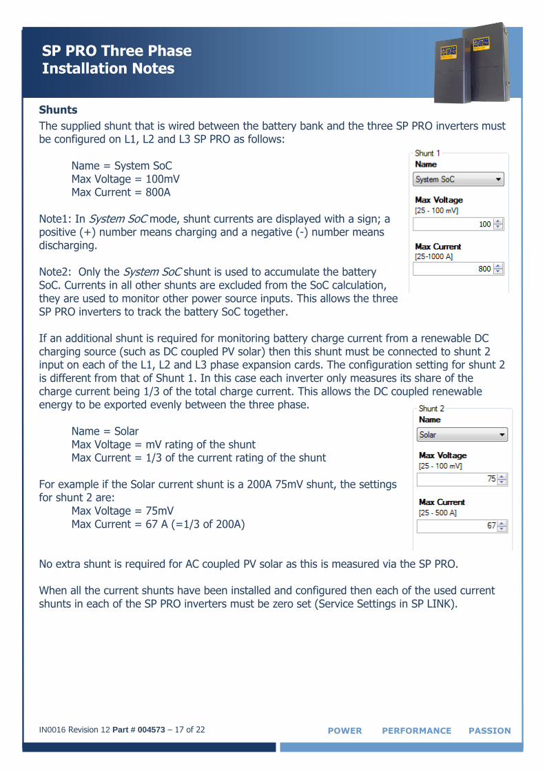
The supplied shunt that is wired between the battery bank and the three SP PRO inverters must be configured on L1, L2 and L3 SP PRO as follows:
Name = System SoC Max Voltage = 100mV Max Current = 800A
Note1: In System SoC mode, shunt currents are displayed with a sign; a positive (+) number means charging and a negative (-) number means discharging. Note2: Only the System SoC shunt is used to accumulate the battery SoC. Currents in all other shunts are excluded from the SoC calculation, they are used to monitor other power source inputs. This allows the three SP PRO inverters to track the battery SoC together. If an additional shunt is required for monitoring battery charge current from a renewable DC charging source (such as DC coupled PV solar) then this shunt must be connected to shunt 2 input on each of the L1, L2 and L3 phase expansion cards. The configuration setting for shunt 2 is different from that of Shunt 1. In this case each inverter only measures its share of the charge current being 1/3 of the total charge current. This allows the DC coupled renewable energy to be exported evenly between the three phase.
Name = Solar Max Voltage = mV rating of the shunt Max Current = 1/3 of the current rating of the shunt
For example if the Solar current shunt is a 200A 75mV shunt, the settings for shunt 2 are:
Max Voltage = 75mV Max Current = 67 A (=1/3 of 200A)
No extra shunt is required for AC coupled PV solar as this is measured via the SP PRO. When all the current shunts have been installed and configured then each of the used current shunts in each of the SP PRO inverters must be zero set (Service Settings in SP LINK).
IN0016 Revision 12 Part # 004573 – 18 of 22
SP PRO Three Phase Installation Notes
POWER PERFORMANCE PASSION
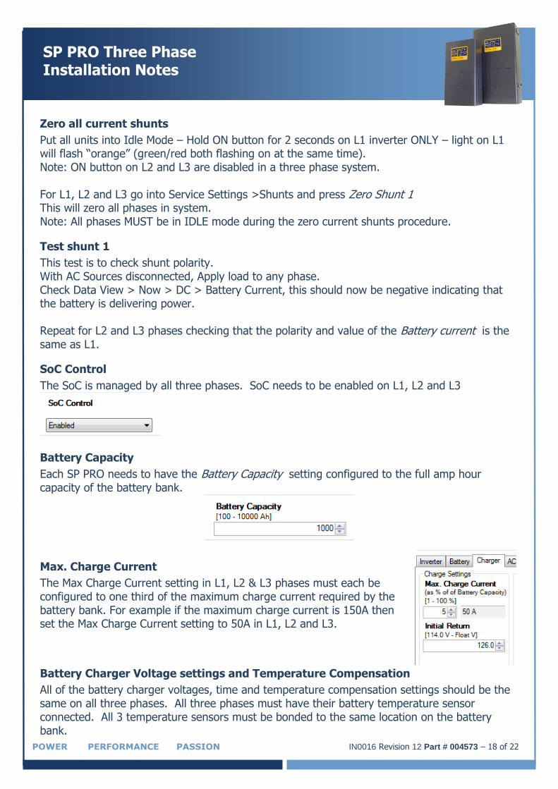
Zero all current shunts
Put all units into Idle Mode – Hold ON button for 2 seconds on L1 inverter ONLY – light on L1 will flash “orange” (green/red both flashing on at the same time). Note: ON button on L2 and L3 are disabled in a three phase system. For L1, L2 and L3 go into Service Settings >Shunts and press Zero Shunt 1 This will zero all phases in system. Note: All phases MUST be in IDLE mode during the zero current shunts procedure.
Test shunt 1
This test is to check shunt polarity. With AC Sources disconnected, Apply load to any phase. Check Data View > Now > DC > Battery Current, this should now be negative indicating that the battery is delivering power. Repeat for L2 and L3 phases checking that the polarity and value of the Battery current is the same as L1.
SoC Control
The SoC is managed by all three phases. SoC needs to be enabled on L1, L2 and L3
Battery Capacity
Each SP PRO needs to have the Battery Capacity setting configured to the full amp hour capacity of the battery bank.
Max. Charge Current
The Max Charge Current setting in L1, L2 & L3 phases must each be configured to one third of the maximum charge current required by the battery bank. For example if the maximum charge current is 150A then set the Max Charge Current setting to 50A in L1, L2 and L3.
Battery Charger Voltage settings and Temperature Compensation
All of the battery charger voltages, time and temperature compensation settings should be the same on all three phases. All three phases must have their battery temperature sensor connected. All 3 temperature sensors must be bonded to the same location on the battery bank.
IN0016 Revision 12 Part # 004573 – 19 of 22 POWER PERFORMANCE PASSION
SP PRO Three Phase Installation Notes
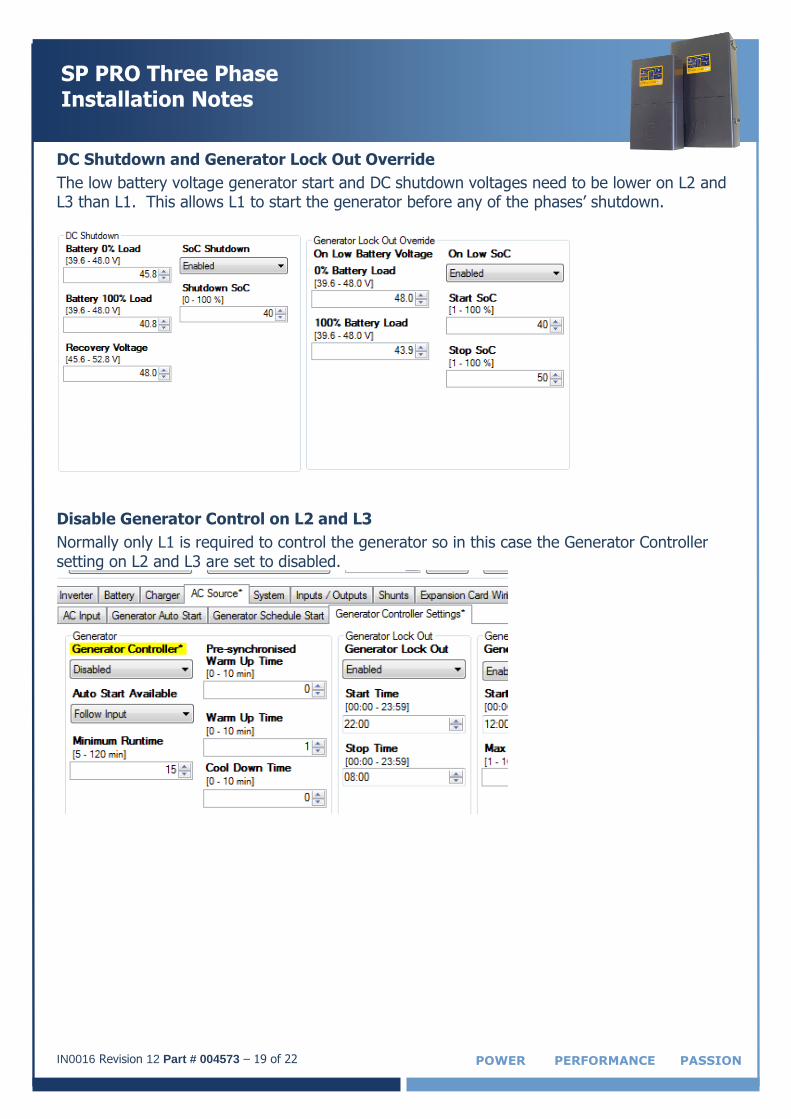
DC Shutdown and Generator Lock Out Override
The low battery voltage generator start and DC shutdown voltages need to be lower on L2 and L3 than L1. This allows L1 to start the generator before any of the phases’ shutdown.
Disable Generator Control on L2 and L3
Normally only L1 is required to control the generator so in this case the Generator Controller setting on L2 and L3 are set to disabled.
IN0016 Revision 12 Part # 004573 – 20 of 22
SP PRO Three Phase Installation Notes
POWER PERFORMANCE PASSION
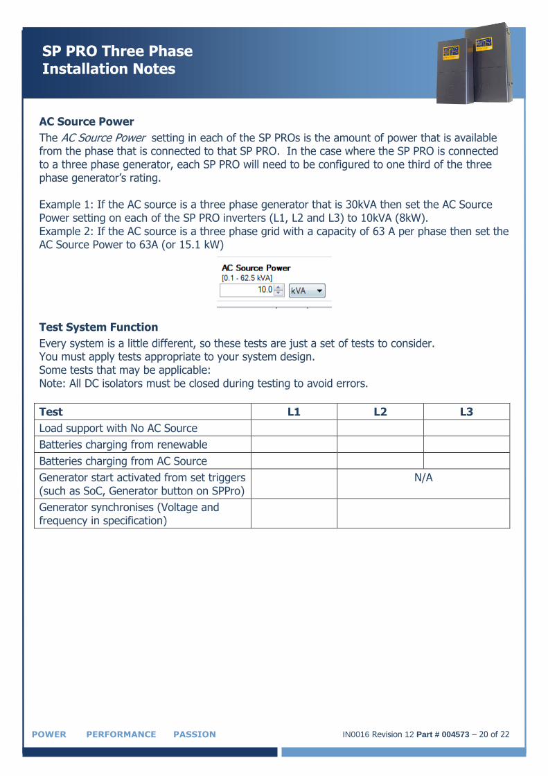
AC Source Power
The AC Source Power setting in each of the SP PROs is the amount of power that is available from the phase that is connected to that SP PRO. In the case where the SP PRO is connected to a three phase generator, each SP PRO will need to be configured to one third of the three phase generator’s rating. Example 1: If the AC source is a three phase generator that is 30kVA then set the AC Source Power setting on each of the SP PRO inverters (L1, L2 and L3) to 10kVA (8kW). Example 2: If the AC source is a three phase grid with a capacity of 63 A per phase then set the AC Source Power to 63A (or 15.1 kW)
Test System Function
Every system is a little different, so these tests are just a set of tests to consider. You must apply tests appropriate to your system design. Some tests that may be applicable: Note: All DC isolators must be closed during testing to avoid errors.
Test L1 L2 L3
Load support with No AC Source
Batteries charging from renewable
Batteries charging from AC Source
Generator start activated from set triggers (such as SoC, Generator button on SPPro)
N/A
Generator synchronises (Voltage and frequency in specification)
IN0016 Revision 12 Part # 004573 – 21 of 22 POWER PERFORMANCE PASSION
SP PRO Three Phase Installation Notes
Solar Hybrid Control
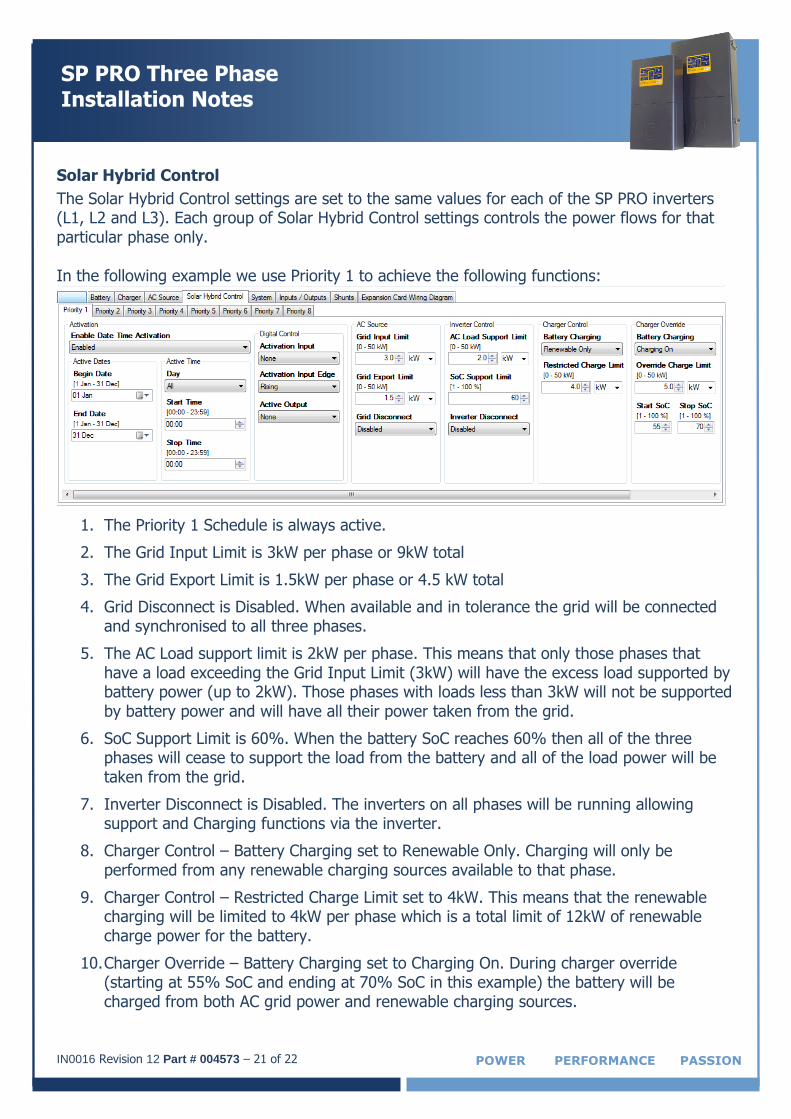
The Solar Hybrid Control settings are set to the same values for each of the SP PRO inverters (L1, L2 and L3). Each group of Solar Hybrid Control settings controls the power flows for that particular phase only. In the following example we use Priority 1 to achieve the following functions:
1. The Priority 1 Schedule is always active.
2. The Grid Input Limit is 3kW per phase or 9kW total
3. The Grid Export Limit is 1.5kW per phase or 4.5 kW total
4. Grid Disconnect is Disabled. When available and in tolerance the grid will be connected and synchronised to all three phases.
5. The AC Load support limit is 2kW per phase. This means that only those phases that have a load exceeding the Grid Input Limit (3kW) will have the excess load supported by battery power (up to 2kW). Those phases with loads less than 3kW will not be supported by battery power and will have all their power taken from the grid.
6. SoC Support Limit is 60%. When the battery SoC reaches 60% then all of the three phases will cease to support the load from the battery and all of the load power will be taken from the grid.
7. Inverter Disconnect is Disabled. The inverters on all phases will be running allowing support and Charging functions via the inverter.
8. Charger Control – Battery Charging set to Renewable Only. Charging will only be performed from any renewable charging sources available to that phase.
9. Charger Control – Restricted Charge Limit set to 4kW. This means that the renewable charging will be limited to 4kW per phase which is a total limit of 12kW of renewable charge power for the battery.
10. Charger Override – Battery Charging set to Charging On. During charger override (starting at 55% SoC and ending at 70% SoC in this example) the battery will be charged from both AC grid power and renewable charging sources.
IN0016 Revision 12 Part # 004573 – 22 of 22
SP PRO Three Phase Installation Notes
POWER PERFORMANCE PASSION
11. Charger Override – Override Charge Limit is set to 5kW. This means that the charging will be limited during Charger Override to 5kW per phase giving a total charging limit of 15kW for the battery.
12. Start SoC and Stop SoC are set to 55% and 70% respectively. When the SoC drops to 55% and before it rises back to 70% the Charger Override limits apply (points 10,11)
Synchronising SoC between inverters.
Each of the three inverters track the battery SoC and use this for the generator control and the Solar Hybrid Schedule. When the inverters are first powered up the SoC is set to 85%. If this SoC needs to the changed (Service Settings) then the same value must be set in all three SP PROs. When the Battery Charger reaches Float then all three inverters will synchronise by resetting to 100% SoC.
Operation
Once the SP PRO units are installed and configured correctly, the system is controlled by the L1 phase. Changing the system operational mode (from Idle mode to Run mode, or back to Idle) is done via the On button on the L1 phase only. L2 and L3 phases will follow the operational mode of L1 automatically. The On buttons on L2 and L3 phases are disabled. As each inverter is tracking the battery SoC the battery indicators on the front of L1, L2 and L3 should display the same number of bars. Note: It is normal for Phase Sync Error to occur in IDLE and if all DC Connections are NOT CLOSED
Additional Information
This information applies to SP PRO Series II units only. SP PRO web site – http://www.selectronic.com.au or contact the Selectronic Sales Team.
+61 3 9727 6600 www.selectronic.com.au