documentsp
DESCRIPTION
file of hmtTRANSCRIPT
INTRODUCTION
The country, India, is basically an agricultural country where more than 65 %
of population enough food has to be produced. This cannot be produced with our
conventional bullock drawn implements. So there was need felt to invent such
machine which speeds up the agricultural production. Due to this reason the tractor
was invented.
Before we start, it is necessary to know how the word ‘tractor’ is derived. Prior
to 1900, the machine i. e. tractor is known as traction machine (pulling machine).
After 1900, both the words joined by taking ‘tract’ from traction and ‘tor’ from motor
calling ‘tractor’. The tractor is the machine which is used for applying high traction.
In our country, tractors were started manufacturing in real sense after
independence and at present, we are self-sufficient in meeting demand of country’s
requirements for tractors. At present in India, there are different tractor producing
factories present like Hindustan machine tools, Punjab tractors, Kirloskar tractors,
etc. is directly or indirectly connected to agriculture. Moreover for increasing
.
Page | 1

COMPANY PROFILE
BIRTH OF HMT
In 1949 the idea of public sector tools was commissioned to be a corner stone
for the government’s industrial development plans. This led to the birth of
HINDUSTAN MACHINE TOOLS at Bangalore in 1953 which started a single
machine tools factory to produce lathes at Bangalore, in collaboration with M/s
Oerlikon of Switzerland.
Next, the company widened its product range beyond lathes by entering into
technical collaboration with other international leaders in machine tools such as Fritz
Werner, Herman Kolb, Errantly Somua, Gildermeister, Liebherr etc.
The second machine tool unit was set up in Bangalore in 1961 making use of
the Company’s own resources. The company diversified itself when, in collaboration
with Citizen Watch Company of Japan, the first watch factory was setup in Bangalore
in 1962 to produce hand watches.
The third machine tool unit was set up in 1963 at Pinjore, Haryana to produce
milling machines. In next few years, Machine Tool Units were set up at Kalamessary
in Kerala and in Hyderabad. The Printing Machinery division was attached to
machine tools factory at Kalamessary to qualities Printing Machine.
HMT’s tractor business commenced its operations in 1971 in technical
collaboration with M/s MOTOKOV, Czechoslovakia because of the priority given to
the agriculture in the national development plan and to take advantage of the green
revolution. HMT started the operations with the manufacturing of 25 Hp tractors.
Over the years, it has developed tractors ranging from 25 – 75 Hp.
The unit in Hyderabad began to make lamps and lamp making machines in
1973 to cater to the growing needs of rural. This was followed by producing
automatic watches.
A third watches factory was established in Srinagar to manufacture hand
wound watches for men. In 1975, the company took over the machine tool
corporation of India’s unit in Ajmer, Rajasthan and its name was changed to HMT
Limited.
In 1975, a separate international scales network called HMT was set up
comprising of company’s own agencies as well as other sales agents in Australia,
Page | 2

Europe and America. This network was to handle the marketing strategy and
operations of the company overseas and it also extended its services to the other
leading Indians and overseas engineering companies. Since then this international
arm of the company has set up the turkey project in Algeria, Indonesia, Iraq, Kenya,
Nigeria and Srilanka.
HMT’S PRODUCTS
HMT PRODUCTS
The main products produced by HMT ltd are –
Machine tools,
Watches,
Tractors,
Bearings,
Printing Machinery,
Die Casting Machinery.
The divisions of HMT are described below –
BANGALORE
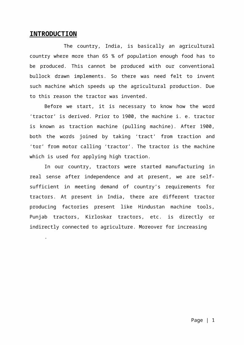
It produces lathes (both CNC and Non CNC), milling/ machining centers,
grinding machines, gear cutting machineries, simple drilling machines, special
purpose machines, die casting and plastic injection moulding.
It also produces refurbishing and retrofitting like heavy duty, turret lathe, multi
spindle drilling machines and fine boring machines.
Page | 3

The other application components include the jigs, fixtures, some radar and
transonic components. It also develops hinomerik control system, Hyderabad.
CNC MACHINE
HYDERABAD
It produces the machining centers, CNC, Boring machines, milling machines,
die and mould machining centers, presses and brakes. It also produces special
purpose machines like CNC tube chamfering machines, cam shaft milling machines,
filament winding machines, horizontal and vertical coil winding machines, multi
spindle machining centers.
KALAMESSARY
It produces CNC lathes and printing machineries.
Page | 4
AJMER
It produces grinders and lathes. It also manufactures some application
components like hydraulic lift mechanism for tractors, valve devices and oil priming
pump.
CNC MACHINE
After establishing two machine factories and a watch factory in Bangalore, the
Pinjore unit was established as the third machine tool factory. Breaking the ground
on 2nd may, 1962, this factory
Page | 5

TRAINING CENTRE
In training centre, the basic machines are studied such as Lathe Machine,
Milling machine, Drilling Machine, etc.
STRUCTURE OF TRAINING CENTRE
TURNING SECTION
In turning section, we have learnt about the lathe machine which is mother of
all machines and play a basic role in mechanical line.
LATHE MACHINE
Lathe is probably the oldest machine tools. The basic idea about turning or
lathe machine came out in 17 century. Until 1770, lathes were useless metal cutting
because they lacked power and holding device, were not strong enough and
accurate enough to guide the tools. For its development to the form in which we
know it now, we owe much to Henry Muldsley, who developed the sliding carriage
and in 1880 built a screw cutting lathe.
Page | 6
TRAINING CENTRE
TURNING SECTION
FITTING SECTION
MILLING SECTION
TRACTOR TRAINING SECTION

LATHE MACHINE
CLASSIFICATION OF LATHE MACHINE
1. Engine Lathe,
2. Speed Lathe,
3. Turret Lathe,
4. Toll Room Lathe,
5. Hollow Spindle Lathe,
6. Capstan Lathe,
7. Bench Lathe.
Lathe is also called Complete Machine. This single machine can do number of
operation.
FACING
This operation is carried out to produce flat surface at the end of part, which is
useful for parts that are attached to other components, or face grooving to produce
grooves for O-ring seals.
DRILLING
In this process a drilling of desire diameter is held in the tail stock and the
operation of drill is carried out.
Page | 7

BORING
In this enlargement of hole or cylinder cavity made by previous process is
done. It improves accuracy and surface finish.
THREADING
In this operation internal and external threads on the surface are prepared.
KNURLING
In this operation a regularly shaped roughness is prepared on the cylindrical
surface for fascinating easy gripping.
FITTING SECTION
Fitting work is very important work in engineering. In fitting shop unwanted
material is removed with the help of hand tools. It is done for mating, repair and
manufacturing purpose. The person working in fitting shop is called as fitter.
Commonly used tools are hacksaw, files, chisels etc.
TOOLS USED IN FITTING SHOP
1. Clamping Tools
2. Measuring and Marking Tools
3. Cutting Tools
4. Striking Tools
5. Drilling Tools
Page | 8

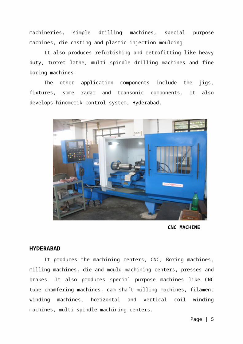
MILLING SECTION
Milling machine were basically developed to machine flat surface. But, the
present machine can machine flat, countered and helical surfaces, cut gears and do
various other jobs. Due to this all milling machine is one of the most useful and
necessary machine tools found in the shop and it rank next to the lathe in
importance.
Milling machine are designed to hold and rotate milling cutter or cutters, hold
the work piece and feed the work piece to the milling cutter in one several directions.
MILLING MACHINE
Page | 9

FOUNDRY MECHANISMS
Since there are certain basic steps in the metal casting process, these may be
used as unit of mechanism.
Processing steps which lead them to the mechanism are:
Page | 10
FOUNDRY MECHANISM
SAND PREPARATION
CORE MAKING
MOULDING,POURING AND SHAKEOUTS
MELTING
CLEANING
PARTS OF FOUNDRY SHOP
Page | 11
FOUNDRY SHOP
SAND PLANT SYSTEM
SAND HANDLING
SYSTEM
CORE MAKING AND BAKING
SYSTEM
MOULDING MAKING AND
HANDLING
CORE SETTING SYSTEM
MELTING SYSTEM
METAL POURING SYSTEM
TESTING LAB
FETTLING SECTION
PAINTING AND PRINTING

SAND PLANT SYSTEM
The main objective of it is to reuse the used lad to the installation of sand
plant system. The vital task of sand plant system is to deliver well prepared sand at
required place that will determine the efficient working of the foundry. After casing
are knocked out of moulding box on a vibratory shakeout box that the used sand is
returned to the fixed amount of new sand, binders, catalysts and hardeners to get to
the required composition of the sand. Green sand, dry sand and oil sand are being
prepared in the sand plant. These constitutes are added in Muller in which all
contents are mixed thoroughly and then supplied via belt conveyor system to
working stations.
GREEN SAND COMPOSITION
Muller batch capacity 700 kg
New sand 35 kg (5%)
Bentonite 660 kg (94.4%)
Water 3.6 kg (0.4 %)
Return sand 1.4 kg (0.2%)
DRY SAND COMPOSITION
Return sand 80%
New sand 10%
Bentonite 1.2%
Dextrin 1.8%
Moisture 7%
COMPOSITION OF OIL SAND (100 KG OF SAND)
Bentonite 12 kg
Dextrin 25 kg
Linseed oil 15 kg
Moisture 20 G
Page | 12

SAND HANDLING SYSTEM
For handling the sand i. e. move it from one place to another, the bucket
elevator and belt conveyor are used.
BUCKET ELEVATOR
When sand is to be conveyed vertically upward, a bucket is ideal. There are
two pulleys, one at the top and other at the bottom which carry an endless belt. The
belt carries number of buckets all around and the whole assembly is enclosed in
steel casting which has two openings, one at bottom for feeding and other at top for
discharge.
BELT CONVEYOR
It is used for transferring sand from one place to another. It consist of endless
belt, two pulleys or idlers for carrying a loaded belt and returning the empty belt, a
belt tightening mechanism and the belt cleaner. The angle of inclination should not
be exceeding 150 for dry sand.
CORE MAKING AND BAKING SYSTEM
As patterns are made to get to outer shape of the casting, the inner shapes
are used to for whole generation core placed in the moulds. As the core comes in
contact of molten metal that must possess following characteristics:
1. Core sand must have high strength to bear the pressure of metal when
poured.
2. The sand must have high refractory characteristics so that it may not fuse due
to high temperature being in contact with molten metal.
3. It must have high cohesive property so as to get good finish castings.
Zircon paint (alcohol base) dried just by lightning it up. Large and heavy cores
are baked along with the dry sand moulds in oven.
Core drying cycles for oven:
3000 C – 1 12
hrs.
Page | 13

2000 C - 212
hrs.
Cooling time in oven 3 hrs.
After baking, the hardness is tested by using hardness meter
CORE MAKING
MOULD MAKING SECTION
Moulds are being made on moulding machine pedantically powered rammers.
Metallic patterns are being used. After mould being made on moulding machine, it
goes to sand cutter which removes extra sand present and level the mould base,
from on to the power operated roller conveyor, the mould is handled using the swing
type crane. Core setting is done in drag part of mould. Zircon painting is sprayed on
to the mould (as paint is alcohol based hence get dry up by lighting fire.
Page | 14

MOULD MAKING
MOULD BAKING
Dry sand moulds are to bake to acquire hardness to with sand the pressure
produced by the flow of molten metal. These are baked in ovens. Mould baking
cycles for ovens 300C for 212
hrs. and Cooling time in oven 3 hrs.
MELTING SECTION
It is having two types of furnace.
1. Electric induction furnace,
2. Copula furnace.
FETTLING
After they are knocked out on vibrator shake, the casting head to be finished
by the removal of projections whether they are gets riser or runner that where there
as a part of design aspect or the projection which has appeared as a defect like fins
or blow holes. The process that involves all these procedure of casting finish is
termed as fettling.
Fettling operation is divided into following stages:
Page | 15

1. Knocking out of dry sand cores,
2. Removal of gates and risers,
3. Extraction of fins and other projections,
4. Cleaning and smoothing of the surface,
5. Repair casting by filling of the blow holes, straightening the wrap or deformed
casting.
PRIMING AND PAINTING
After all the cleaning process has been performed then the final step is
priming and the painting casting. The machine tool castings are generally big and
are handled with crane during painting. Painting is done by brushes only.
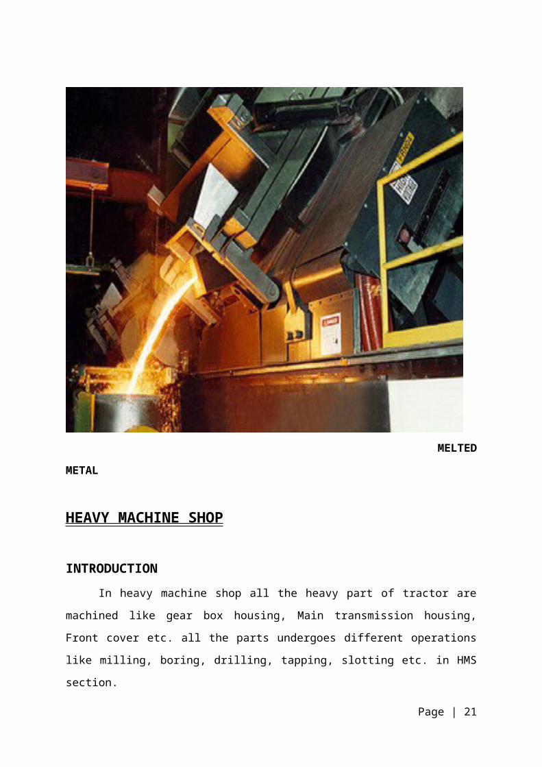
MELTED METAL
Page | 16

HEAVY MACHINE SHOP
INTRODUCTION
In heavy machine shop all the heavy part of tractor are machined like gear
box housing, Main transmission housing, Front cover etc. all the parts undergoes
different operations like milling, boring, drilling, tapping, slotting etc. in HMS section.
The entire machines in this section are special purpose machine; it means the
machine doing special or specific operation on a job.
The advantage of special purpose machine is that it increases the rate of
production. The machines are capable of machining any number of identical parts in
a very less time.
PARTS MACHINED IN HMS
1. Gear box housing
2. Main transmission housing
GEAR BOX HOUSING
Gear box housing is used for fitment of gears and shafts. The material used
for Gear box housing is cast iron.
GEAR BOX HOUSING
Page | 17

PROCESS OF MANUFACTURING OF GEAR BOX HOUSING
OPERATION
MARKING THE GEAR BOX HOUSING
With help of crane, we put the housing on the surface plate and after this with the
help of vernier height gigue we mark the gear box housing. Marking is done of the
gearbox is done for remove the all allowances material.
BOTTOM MILLING
With help of crane we put the work piece on the milling machine (SPM). Bottom
milling is done for removing the extra material on the gear box housing.
DRILL THE LOCATION HOLE ON THE GEAR BOX HOUSING Location
holes are made for fix the housing on the different machine.
TOP MILLING
Put the housing on milling machine according to location holes. Top milling done for
removing the extra material on the housing.
Page | 18
MARKING THE GEAR BOX HOUSING
BOTTOM MILLING
DRILL THE LOCATION
HOLE
TOP MILLING FRONT AND REAR COVER
LEFT AND RIGHT MILLING
SLOT MILLING
BORINGPRE BORING OF STEERING
BORE
HEAVYY DUTY DRILLING
BOTTOM MILLING HOUSING
TAPPING DRILLING FOR CLUTCH
FINAL BORE
WASHING
INSPECTION

FRONT AND REAR COVER
According to their location of hole we fix the work piece on the milling machine. For
removing the all allowance on to the housing.
LEFT AND RIGHT MILLING
For removing the all allowance on to the housing.
SLOT MILLING
In this milling we made the slots for gear forks which used for change the gears.
Dimension of slot is 16mm.
BORING
Boring is done for removing extra material from bores to make the bore according to
their dimensions.
PRE BORING OF STEERING BORE
Pre boring is done for removing the allowance from steering bore.
HEAVY DUTY DRILLING
It is done for making the drilling in to the housing for joining purpose.
BOTTOM MILLING HOUSING
20 drills simultaneous.
TAPPING
Tapping is for making the internal thread in to the drilled holes and for joining
purpose.
DRILL FOR CLUTCH AND PEDAL
For joining the clutch and pedal drilling is done on both faces right and left on the
gear box housing.
Page | 19
FINAL BORES ON THE ALL BORES
steering bore, reverse gear and shaft boring on the boring machine.
WASHING
Washing the gear box housing.
INSPECTION
Inspect the housing for defect like blow hole or others.
Page | 20
MAIN TRANSMISSION HOUSING
Main Transmission Housing is manufacturing in heavy machine shop. M.T.
Housing is used for setup the differential and axle assembly. Material used for M.T
Housing is cast iron.
MAIN TRANSMISSION HOUSING
MANUFACTURING PROCEDURE OF M.T HOUSING
Page | 21
MARKING M.T
HOUSING
HORIZONTAL MILLING.
RADIAL DRILLING
HORIZONTAL MILLING
BORING
MILLING BORING FINISH
WASHING
INSPECTION

MARKING M.T HOUSING
With help of crane we put the housing on the surface plate and after this with the
help of vernier height gauge we mark the M.T. Housing according to their
dimension. White paint is used foe marking.
HORIZONTAL MILLING.
Horizontal milling is done for removing the extra material or allowances according to
their drawing
RADIAL DRILLING
Radial drills are used for the made the location holes in the housing and these
locations are used for seat the job on the different type of machine.
MILLING OF M.T. HOUSING
In this operation milling of four faces is done front, rear, left and right. In operation
we fix the job on their location and holes and after we do milling.
BORING
In this boring operation we do rough boring of front, left & right bores.
Dimensions of bores:
Left hand bore: 290mm.
Right hand bore: 288& front hand bore: 90mm
HORIZONTAL MILLING ON FRONT
Horizontal milling is done for remove the extra material or allowances according to
their drawing. Horizontal milling is done on SPM milling machine.
BORING FINISH
After horizontal milling we put the housing on the boring machine on their location
holes. it is done for finishing purpose.
WASHING
Page | 22

Washing is done to remove chips and oil. this is done after all the operation.
INSPECTION
Inspection of work piece according to their drawing.
Page | 23

LIGHT MACHINE SHOP
INTRODUCTION
As the name suggests that in this section light parts or small parts of tractors
are machined such as speed gears of tractor, sun & planet gears crown wheel, PTO
shaft, clutch shaft, spline shaft, front and rear axle.
SPLINE SHAFT
A shaft with longitudinal gear like ridges along its interior or exterior surface
is called spline shaft. the function of spline shaft is to transmit the power from
flywheel to lay shaft. Material used for spline shaft is low carbon steel.
SPLINE SHAFT
Page | 24
PROCESS FOR MANUFACTURING OF SPLINE SHAFT
After these process spline shaft send to heat treatment plant for hardening
process.
1. Gas carburizing & hardening.
2. Tempering
3. Shot blasting.
4. Straightening.
5. Centre grinding.
6. Internal grinding.
7. Fitting.
8. Inspection
Page | 25
RAW MATERIAL
CUTTING OF SHAFT
FACING AND CENTERING
CNC TURNING
INSPECTION
GEAR HOBBING.
GEAR TOOTH
ROUNDINGFITTING.
WASHING. INSPECTION GEAR SHAVING.
BENCH DRILLING

BEVEL PINION SHAFT
Bevel pinion shaft is used for transmit the power from gear box to differential.
The material used for it is low carbon steel.
BEVEL PINION SHAFT
PROCEDURE OF MANUFACTURING OF BEVEL PINION SHAFT
Page | 26
RAW MATERIAL
MATERIAL CUTTING
FACING
TURNING
INSPECTION
GEAR HOBBING
FITTING
WASHING
GAS CARBURIZI
NG
ANNEALING TURNING
CYLINDRICAL GRINDING
THREAD ROLLING
DRILLING
TEMPERING SHOT BLASTING
STRAIGHTENING
WASHING & INSPECTION

WHEEL SHAFT
Wheel shaft is assembled in axle housing and its transmit torque to wheels.
WHEEL SHAFT
Page | 27

MANUFACTURING PROCEDURE OF WHEEL SHAFT
Page | 28
RAW MATERIAL
FACING DRILLING
RADIAL DRILLING
GEAR HOBBING
INSPECTION
INDUCTION HARDENING
TEMPERING
CYLINDRICAL GRINDING
THREADING
FITTING
HORIZONTAL MILLING
FITTING
INSPECTION

HEAT TREATMENT
All components (manufactured in LMS) after undergoing machining operation
are subjected to heat treatment. It is done so as to improve hardness and strength of
these components viz. gears and shafts.
Basic operations performed during heat treatment:
1. Hardening,
2. Quenching,
3. Annealing,
4. Tempering,
5. Normalizing,
6. Carburizing.
Melting temprature: 6400C,
Carburizing media 13- 15 % sodium cyanide + 85 % BaCl + NaCl
HARDENING
For medium carbon steel and high carbon steel 8400C- 8500C
For other 770 – 8200C
Hardening is performed on the various metals and its alloys to provide them
with strength and wear resistance. It is accomplished by heating the component
above its hardening temperature and quenching it in water.
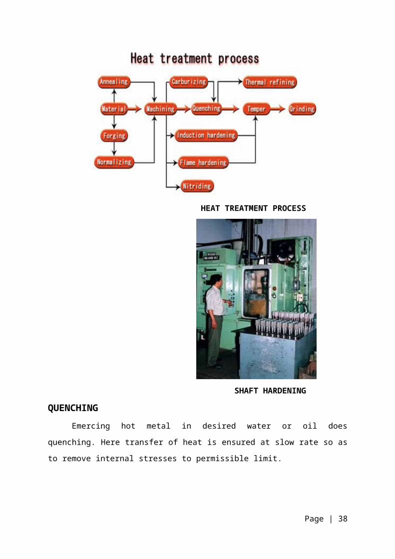
HEAT TREATMENT PROCESS
Page | 29

SHAFT HARDENING
QUENCHING
Emercing hot metal in desired water or oil does quenching. Here transfer of
heat is ensured at slow rate so as to remove internal stresses to permissible limit.
QUENCHING MACHINE
Page | 30

QUENCHING FURNACE
NORMALIZING
In this process, iron alloy casting is heated to 50 – 600C above critical
temperature range. The casting is held for definite time and then allowed to cool in
still air. Normalization eliminates casting or cooling strains and resultant casting is
easy to machine.
CARBURIZING
Process of adding carbon to surface layer of the component is called
carburizing. It is the process of casehardening, which is addition of some elements
like carbon, nitrogen to the surface by diffusion for surrounding medium at high
temperature the purpose of carburizing is to obtain high surface wear resistance and
obtain a hard surface.
TEMPERING
For medium carbon steel and high carbon steel 6700 - 6800 C
Page | 31

for fasteners tempering to be done at 3500 – 4000 C for 1 – 2 hrs.
In tempering long grains formed during quenching are broken into smaller
grains so as to improve elasticity of the material. Here heating is done at around
1800 - 2000 C for around 2 hrs. and then cool in air. It reduces internal stress and
stabilizes the structure of metal.
ANNEALING
For medium carbon steel and high carbon steel 6800 – 6900 C.
CASE HARDENING
Carburizing + hardening.
PROCESS USED FOR BLACKENING
1. Job is clean with cotton waste.
2. Put the job in the NaOH solution for 10 to 20 min. for de-greasing or
decomposition.
3. Wash it with warm water.
4. De-rust the job in the rust solution.
5. Wash it with water.
6. Shift it to blackening furnace at 1200 C for 10 – 20 min. according to sectional
area
Page | 32

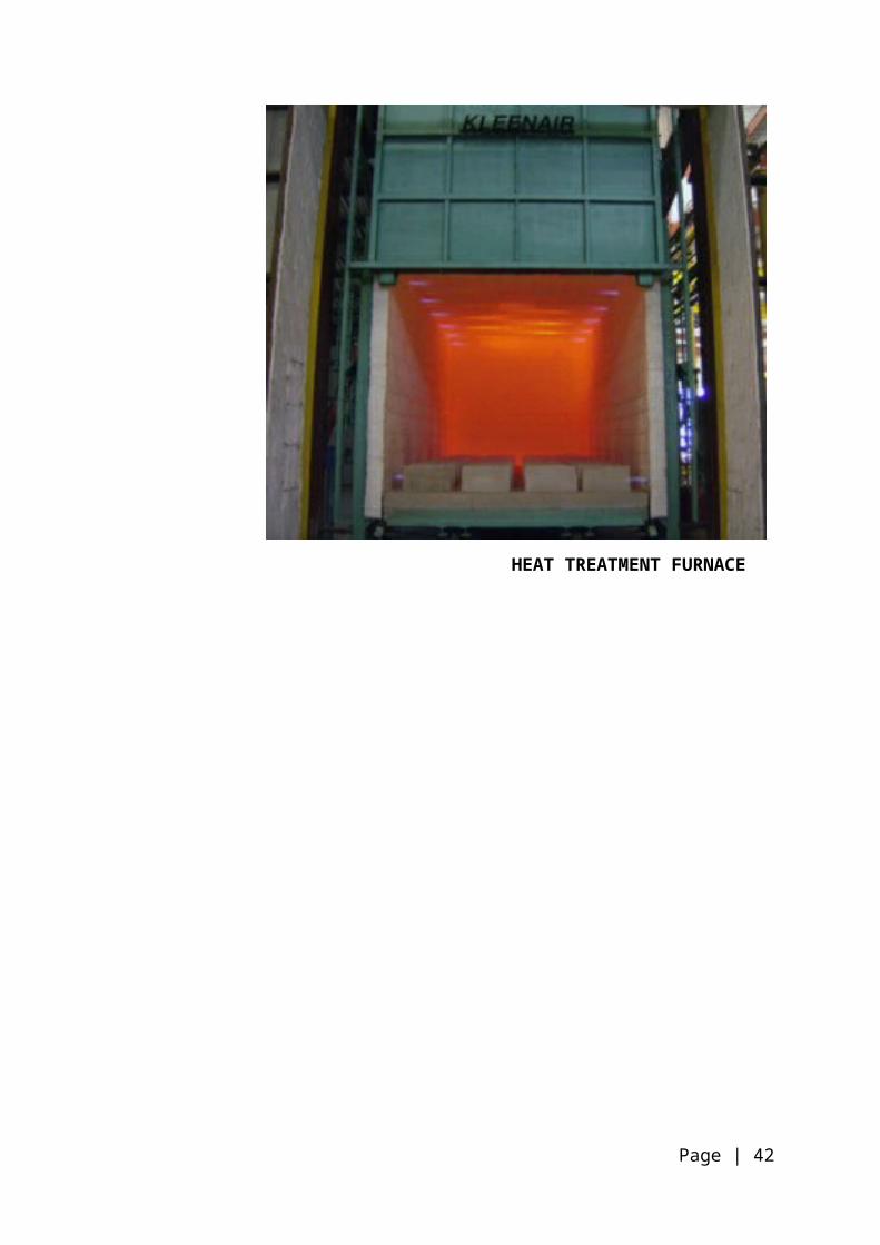
HEAT TREATMENT FURNACE
Page | 33

ENGINE ASSEMBLY
CRANKSHAFT FITTING
First of all bush type liners are inserted into the bearing holes. The liner is
provided with recess to store a minimum amount of oil, which wets as the crankshaft
during storing engine. The bearing cap is opened and crankshaft assembly is placed
into it. The bearing cap is tightened again with 10-12 kg-m torque rod and crankshaft
is checked that it is revolving easily or not
CRANK SHAFT
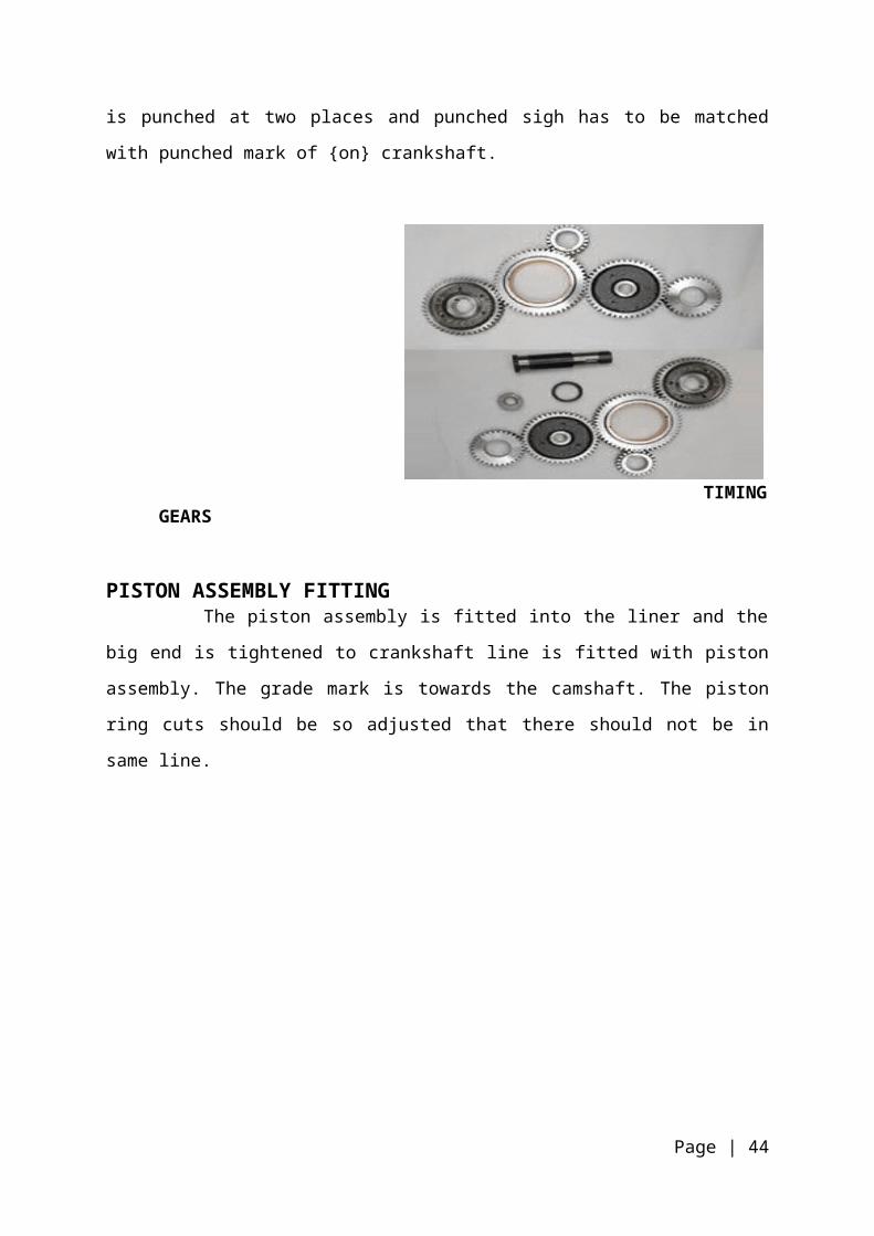
TIMING GEAR FITTING
The idle shaft is pushed into the crankcase and roller type bearing with lock is
inserted into the shaft. The idle timing gear is then pressed into the bearing. The
timing gear is punched at two places and punched sigh has to be matched with
punched mark of {on} crankshaft.
Page | 34

TIMING GEARS
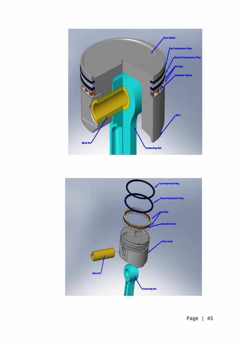
PISTON ASSEMBLY FITTING The piston assembly is fitted into the liner and the big end is tightened to
crankshaft line is fitted with piston assembly. The grade mark is towards the
camshaft. The piston ring cuts should be so adjusted that there should not be in
same line.
Page | 35

ASSEMBLY OF PISTON AND CONNECTING ROD WITH CRANK SHAFT
Page | 36
LUBRICATION OIL PUMP MOUNTING
The lubrication oil pumps connected to crankshaft gear by an idle gear of 2-3
degree. The crankshaft and pump gear has 22 teeth each. The pump is provided
with relief valve through which it opens at 4kgf.
In the case of are loading or something injected in the main gallery then pressure is
released from their valves.
LUBRICATION OIL PUMP PARTS
Page | 37
REAR COVER AND FRONT COVER MOUNTING The rear cover and front cover are cleaned perfectly with air and filled to engine
with seals in between mounted
FRONT END COVER REAR END COVER
CAM SHAFT FITTING The camshaft is inserted into the camshaft hole with bearing and bolt ends are
locked by circle. The camshaft is forged from alloy steel or cast iron and is case
hardened. The one end of the camshaft is provided with gear, which is locked, gear
z-50 for exact timing of the camshaft gear mark is matched with the mark on idle
gear. Another gear pump is attached with idle gear, which serves the purpose of
driving the fuel injection pump.
CAM SHAFT
Page | 38

FLYWHEEL MOUNTING The flywheel is mounted on the crankshaft and bolts are tightened with 11-12
kg-m force. The F.I.P is connected to F.I.P gear through F.I.P shaft
The F.I.P drive shaft is specifically designed to advance the time of injection.
The both ends of F.I.P drive shaft is provided with spline, One side a key is provided
which is locked to timing gear and recess on their side is pushed into F.I.P slots. The
angle between the key and recess of 18 degree thus the fuel injection is advanced
by 18 degree.
FLYWHEEL
SETTING OF FUEL INJECTION PUMP WITH RESPECT TO
CRANKSHAFT
This timing is set by setting the flywheel i.e. crankshaft angle into particular
designed value by using following procedure:-
1. First of all, supply of fuel injection pump is disconnected from the 1st cylinder.
2. Rotate the flywheel to make the piston executing compression stroke in the
same cylinder.
3. Then a flask containing fuel, is placed at a level higher above the pump and
inlet to pump is connected to the flask by a pipe. This arrangement provides
inflow of fuel to the F.I. pump.
Page | 39

4. Outlet of F.I. pump is connected to a small pipe to collect the fuel.
5. Now the flywheel is rotated so that piston moves towards the TDC. As we
know when piston moves towards the TDC, the plunger in the F.I pump
covers the spill port and fuel starts flowing out through the outlet pipe.
6. Now the flywheel is brought to the marked position according to design and
then the F.I. pump is tilted, keeping its input shaft fixed so that fuel starts
flowing out.
7. Now the FI pump is fastened on the same position.
CYLINDER HEAD MOUNTING
The cylinder head assembly is placed on the piston and studs are passed
through it. If the height of the piston at TDC from the surface is more then 0.1 mm
than the gasket of given thickness are used. If it is 0.1 to 0.5 mm then 1.2mm thick
gasket is used. If it is 0.5 to 0.8mm then 1.5mm thick gasket is used. The cylinder
nuts are tightened by 17-18 kg-m forces.
WATER BODY AND PULLEY MOUNTING
The water body is mounted with thermostat control valve opens at 70 degree
Celsius. The pulley is mounted on camshaft.
The assembly is removed from the trolley, is placed on the stationary frame.
Page | 40

FUEL INJECTION PUMP MOUNTING AND SETTING OF FUEL
INJECTION PUMP
The gear of F.I.P is first of all meshed with F.I.P drive shaft and is loosely
tightened to set the timing of gear first of all pointer is tightened on the crankcase
and flywheel us rotated which is meshed for 16, 18, 20, 24 angles. The pointer is set
at 18 of flywheel and then pump is rotated clockwise till one from first nozzle stop out
blowing. At this position a cut mark is made on both the pump and crankcase for
further setting. The pump is tightened properly and pipes are tightened over nozzle
and injectors. The head of position is covered with covers and the complete engines
are sending to engine testing shop. The whole of engine shop is air-cooled.
FUEL INJECTION PUMP
Page | 41
ENGINE TESTING
INTRODUCTION
Engine testing is done for checking the performance of newly assembled
engine to find out any assembly fault, their HP, leakage and other fault. Engine
testing shop of standard is equipped with latest digital control equipment. The engine
testing is done with the help of turbine (water) or hydro dynamometer is four in
number so that four engines are tested at one time. The shop is equipped with heavy
duty oil filter, which is used to clean the oil from dust or other large particles the shop
has bush pump tester is measured on the based of S.A.E rating. The society of
automobile engineer’s USA has specified die method of measuring the power output
of the engine for standardized purpose. The engine is run without generator.
TRACTOR TESTING
Tractor testing is done under the international organization for standardization
(ISO). The first tractor with an internal combustion engine was introduced in
American agriculture in the year 1889. The tractor testing act was passed in U.S.A in
1920. In India tractor testing station was finally establish at Budani in 1959 for tractor
testing atmospheric pressure shall not be less than 96.6 Kpa. The basic task is
design and development of engines is to reduce the cost and improve the efficiency
and the power output. In order to achieve the above task the development engineer
has to compare the developed engine with the other engines in terms of its output
and efficiency. Towards the end, engineer has to test the engine and make
measurements of relevant parameters that reflect the performance of the engine
ENGINE TESTING AT STANDARD TRACTORS, PURPOSE OF TESTING A TRACTOR ENGINE
In general purpose of testing an I.C engine is to determine the following:
1. To determine the rated power output with respect to the fuel combustion
in kg per kw hr brake power output
2. To determine the mechanical and thermal efficiencies of the engine
3. To see the performance of the engine at different loads
4. To determine the quality of lubricating oil required per B.P.Kw-hr.
Page | 42

5. To determine the quality of cooling water required per B.P.Kw-hr.
6. To determine the overload carrying capacity of the engine
7. To prepare the heat balance sheet of the engine
SOME IMPORTANT TERMS AS ISI STANDARAD TERMINOLOGY
SPEED
The speed of a engine is the mean speed of its crankshaft in R.P.M expect in
the case of free piston engines where the speed is the number of cycles per minute
of the reciprocating components.
STEADY LOAD SPEED BAND
It is the maximum total variation in speed expressed as a percentage of the
mean speed, which may occur while there is no change in the external load
conditions
CONTINUOUS POWER
The power which engine is capable of delivering continuously between the
normal maintenance intervals stated by the manufacturer at the stated speed and
under stated operating conditions
INDICATED POWER
It is the total power developed in the working cylinder by the gases on the
combustion side of the working pistons
FRICTION POWER
It is the power consumed in friction resistance
BRAKE POWER
It is the total power consumed in friction resistance
Page | 43
FUEL CONSUMPTION
It is the quantity of fuel consumed per unit power per unit of time. It is general
expressed in grams of fuel consumed per B.H.P.
MECHANICAL EFFICIENCY
It is defined as the ratio of the power obtained at crankshaft i.e. brake power to
the indicated power.
Thus mechanical efficiency = brake power (B.P.) / indicated power (I.P)
THERMAL EFFICIENCY
INDICATED THERMAL EFFICIENCY
It may be defined as the ratio of heat converted into indicated work to the heat
energy supplied by the fuel, during a specified period of time.
So, indicated thermal efficiency
= heat equivalent to I.P per min. / heat supplied by fuel per min. =I.P.
*60 / Mf*CV
BRAKE THERMAL EFFICIENCY
It may be defined as the ratio of heat equivalent to brake power (B.P) to the heat
energy supplied by the fuel during a specified time
So brake efficiency
= heat equivalent to B.P per min. / heat supplied by fuel per min. =B.P. *60 /
Mf*CV
PREPARATION FOR TEST
Test runs shall be made on an engine as being offered to the consumers. Before
starting the engine tests, the engine shall have been thoroughly run in the fuel and
lubricating oil used during the test shall be specified by the engine manufacture
In general the engine operating temperatures and the lubricating oil pressure during
the test shall be maintained at the values recommended by the manufacturer
Page | 44
IN ENGINE TESTING WE NOTE DOWN THE FOLLOWING DATA
1. Revolution per minute (R.P.M.)
2. Fuel time
3. Engine Lub. Oil pressure
4. Water outlet temp.
5. Lubricating oil temp.6. Torque (N-M)7. Smoke reading with the help of bosch smoke meter8. In case of silencer a noise meter & u-tube manometer for measuring
backpressure
With the help of the data we calculate following parameters1. B.H.P = R.P.M *N-M / Dynamometer constant2. IN KILOWATTS = R.P.M *N-M / 9549.3053. Specific fuel consumption (S.F.C) = 297000 / B.H.P*fuel time
Page | 45

TRACTOR ASSEMBLY SHOP
INTRODUCTION Tractor assembly shop is main shop of Standard Tractor division. In this
shop, different machined parts, housing & other components, which are machined in
other shops or purchased from outside, are assembled.
Then sub assemblies like differential housing, gear box, rear cover and other
parts are sent to main assembly line. Then the tractors are sent to painting section.
TYPE OF PTO TRACTOR
1. Multi PTO Tractor
2. Ground PTO Tractor
3. Simple PTO tractor
MULTI PTO TRACTOR
In this type, speed of PTO shaft can be varied as there is an arrangement that
either it can be run from the output of gear box or from input to the gear box, which
provide it 6 speeds of PTO shaft in high speed mode as well as 6 in low speed
mode. However, there is provision that PTO can be run while tractor is not moving
i.e. wheels are in rest position.
GROUND PTO TRACTOR
The basic difference between this type and multi PTO shaft is that it provides
different speeds only when tractor is moving, while Multi PTO shaft can provide
different speeds even when tractor is in rest position.
It is particularly used when PTO is to drive thoster and reaper.
SIMPLE PTO TRACTOR In this type PTO can run only at one speed of 540 rpm, doesn’t matter whether
tractor is moving or not.
ASSEMBLY TAKES PLACE IN FOLLOWING PHASES
1. Differential housing assembly
2. Rear cover assembly
Page | 46

3. Gear box assembly
4. Main assembly line
5. Painting phase
DIFFERENTIAL HOUSING ASSEMBLY It is rear part of the tractor chassis. It is filled with CL-90 hydraulic fluid, which is
used for hydraulic purposes as well as lubricating differential components and gear
box components. PTO shaft is also passed through this housing. Various functions
performed in differential housing are as following:-
1. Differential turns the drive through 90˚ from gear box output shaft to bull gear
shafts which in turn drive rear wheels.
2. Very important function of differential is distribute the power at wheels
according to whether tractor is running straight or is turning towards left or
right.
3. Reduction of speed in two stages; 1st reduction at tail pinion and crown
wheel, 2nd at bull gear and bull pinion gear drive.
TRACTOR ASSEMBLY SHOP
Page | 47

MAIN PARTS OF DIFFERENTIAL HOUSING1. Crown wheel
2. Tail pinion
3. Cage assembly with sun and planet gears
4. PTO shaft
5. Bull pinion shafts; B.P. left & B.P. right
6. Bull gears
7. Bearings
8. Brakes housing assembly
9. Oil seals, Gaskets etc
ASSEMBLY OF CROWN WHEEL
1st of all, all components are washed with oil to remove dirty particles.
Cage has two holes. In these holes dowels are tight fitted for accurate fitting of
crown so that all holes of the cage & crown are in same line. The crown wheel is
pressed on cage with hydraulic press and tightened by bolts with lock washer,
and then the right bevel gear is placed on its cage seat. The four planet gears
are put on across the four arms of rigid member along with the washers. This
assembly is placed in the cage and then left bevel gear is placed. Operator
checks the motion of assembly by manual inspection.
CAGE ASSEMBLY
Page | 48

TAIL PINION ASSEMBLY In tail pinion assembly, cone for tapered roller bearing is fitted with hydraulic press. The bearing is heated before the tight fit. Then tail pinion is inserted inside the bearing. Different no. of shims are used for preloading purposes and proper positioning of tail pinion. Whole assembly is tightened by nuts & bolts.
REAR AXLE ASSEMBLY
In rear axle assembly bolts are tight fitted in the holes of hub. Two
bearings on either side of the trumpet housing are tightened at gang drill.
BRAKE ASSEMBLY Standard tractors are provided with heavy self energizing water sealed disc
brakes with ventilation pipe, which gives better cooling. This ventilation results in
30% reduction in pad temp. Brake housing cover contains two discs made up of
asbestos base. The max temp resistance is about 300˚C. Below these discs there
are two cast iron disc plates (with steel balls), which are held by springs. Whenever
brake is applied, the CI plates rotate and due to presence of balls these plates
moves axially 7 press the brake pads against broke housing and differential housing.
As the brake pads are mounted on BP left & right, therefore above discussed
process results into braking action.
BRAKE ASSEMBLY
Page | 49

PTO SHAFT ASSEMBLY Firstly bearings are fitted on the supports of PTO shaft in the housing and then PTO shaft is inserted through the rear of the housing.
TESTS PERFORMED ON DIFFERENTIAL HOUSING
1. Backlash Testing
2. % age of Contact Test
3. Preloading Test
BACKLASH TESTING
This test is performed with the help of plunger dial gauge. Backlash in crown
wheel is not allowed more than 20 to30 micron. If it deviates from this value then
packing is changed on either side of cage in bearing housing. If it exceeds the 30
micron value then shims are removed from right side and shifted to left side. If it is
less than 20 micron then vice versa. Also run out for crown wheel is 0.5-1 mm.
%AGE OF CONTACT TEST & PATTERN TEST
This test is done with the help of yellow paint. It is applied on some of teeth of
crown wheels. Then it is made to rotate with the help of handle, then tail pinion
meshes with these teeth and meshing leaves impression on the yellow painted teeth.
This impression indicates the contact line on the teeth as well as the point where
contact is broken. The contact shouldn’t brake in a way such that contact doesn’t
follow through the complete tooth width. Proper adjustment can be made by
selecting suitable no. of shims used for fastening the tail pinion assembly on the
housing.
PATTERN TEST
Page | 50

The bull gears are tighten to trumpet housing assembly by lock nut and the whole
assembly is also tightened by nut and studs on the outer side of differential housing.
Then PTO shaft head cover is tightened to protect its outer teeth. The sliding gear
and PTO shifter rod assembly is mounted on differential housing. Two filters are
placed inside the differential housing and then whole assembly is sent to main line.
REAR COVER ASSEMBLY It is used to cover the differential housing. It contains lift control system, which I
hydraulically operated. Driver seat is fitted on the upper side of rear cover. The
Response Valve housing(R.V. housing), control valve, ram cylinder and other
components are fitted inside and outside the rear cover.
The main components of rear cover assembly are:-
1. Control valve assembly
2. R.V. assembly
3. Ram cylinder and piston assembly
4. Operating sector assembly
5. Sensors tube assembly
6. Gaskets, Bolts and Nuts
7. Other components
RAM CYLINDER ASSEMBLY It contains cylinder with piston inserted inside it. The relief valve assembly is
mounted at the top front of cylinder. The connecting rod is placed in piston rear side
and one side is locked with ram arm assembly. Then ram arm, spacer and seals are
placed. The ram arm is keyed to a shaft called rocker shaft. At the end of rock arm
assembly, lift arm assembly is placed and then looked with bolts on both sides.
R.V. ASSEMBLY
It contains one response valve, check valve and release valve. It is also
connected with control valve through pipe housing. The knob is placed on the top of
response valve to close or open the response valve as per requirements.
These days R.V housing and control valve are integrated into single unit.
Page | 51

CONTROL SECTOR ASSEMBLY
It contains the draft control assembly and position control assembly. Both these
assemblies are connected to their respective leavers. The positional control
assembly is connected to black marked leaver & draft control leaver is connected to
red marked leaver. In simple words, positional control leaver lower or up the lift
linkages, while draft control leaver change the sensitivity of sensor.
First of all, rear cover is mounted over the moving trolley and tightened with bolts.
Then operating sector assembly is placed at its respective place. A sensor tube is
placed at rear side of the rear cover. Earlier R.V. housing was used to fit outside the
rear cover which was connected to the control valve through piping in the rear cover
housing. But now these days both R.V. housing & control valve are integrated into
single piece and it is fitted inside the rear cover.
Control valve contains three valves i.e. back measure valve(3-6 kgf), unloading
valve and scroll valve. Oil from pump goes to R.V. through pipes, which is further
connected to the check valve through inner hole of R.V. housing and back pressure
valve of control valve. The operating pressure of check valve is 9-12 kgf and
operating pressure of back pr valve is 3-6 kgf. During un-operated position, the oil
flow continues through back pr valve of control valve.
During operation of position arm the unloading valve closes the gallery of oil to
the back pr valve. Thus the pressure in the R.V. housing builds up which opens the
check valve at 9-12 kgf. At this position, the oil goes in the ram cylinder, which
further operates the lift arm. For requirement of any position of lift, the knob of
response valve of RV housing is rotated which cut the supply of oil and position of
ram arm is achieved. Sensor tube works in the field during ploughing of soil with
harrow. When harrow deeply dug in soil, draft is set at position through sensor tube.
The rocker arm attached to sensor and harrow link, when push the sensor tube
inside and automatically controls oil supply.
GEAR BOX ASSEMBLY
INTRODUCTION
Gear box in the standard tractors is of sliding mesh type. It is the main assembly b/w
the engine and differential housing. Advantages of using constant mesh type gear
Page | 52
box are higher mechanical efficiencies and lower noise level due to use of helical
gears instead of straight spur gear.
It gives the tractor a top speed of 30 kmph and a minimum speed of 2 kmph. There are 5 forward and one reverse gears with a high and low level.
GEAR BOX PARTS
Page | 53

MAIN COMPONENTS OF GEAR BOX
1. Input shaft assembly
2. Output shaft assembly
3. Lay shaft assembly
4. Intermediate shaft assembly
5. Actuator shaft assembly
6. Gears
7. Gear box housing
8. Shifter rods
9. Shifter forks
10.Bearings
11.Fasteners, Gaskets and spacers
12.Planet gear and carrier assembly with internal gear
13.Clutch actuator (C.A.) assembly
TRANSMISSION GEARS
CLUTCH ACTUATOR
Clutch actuator assembly contains clutch actuator guide on which bearing is
tight fitted and locked with circlip.
Page | 54
LAY SHAFT ASSEMBLY
The lay shaft is hollow shaft with splines on the outer surface. One end of lay
shaft is threaded (in case of single clutch) and tightened from front side of gear box
with a hexagonal nut.
The whole assembly consists of gear Z-49 (i.e. constant mesh gear with input
shaft gear), spacer 15 mm, gear Z-42, gear Z-38, spacer 30 mm, gear Z-31, gear Z-
29 and a spacer 25 mm and bearing with a circlip.
In case of dual clutch tractor model, the drive shaft is placed through hollow
lay shaft. The drive shaft consists of splines at one end and a gear (Z-45) on the
other end.
The gears are constantly meshed with the gears on the intermediate shaft.
The main function of the lay shaft is to rotate the fixed gears on it from where we
can get different speeds with the help of sliding gear on the drive shaft.
INPUT SHAFT ASSEMBLY
Input shaft consists of helical gear on one end and splines on the other end.
Splined part is attached to clutch and gear is in constant mesh with Z-49 gear on the
lay shaft. Input shaft is put into gearbox with the bearing, which is locked by circlip.
OUTPUT SHAFT ASSEMBLY
Output shaft assembly consists of a solid shaft with the splines on the outer
surface. The shaft is placed into the bearings and locked by circlip. Some of the
back part of the shaft is projected outside the gear box to get drive from it. The
assembly of shaft consists of gears with no. of teeth 18, 22, 30, 32. The sliding gear
2 is used for 1st and reverse gear; sliding gear 30 is used for 2nd gear and sliding
gear 22 is used for 3rd gear; sliding gear 18 is used for 4th gear and it can be keyed
to the splines of the input shaft for the 5th gear.
ASSEMBLY OF GEAR BOX
First of all, the gear box is mounted over the trolley, which can be moved with
the help of chain conveyor system. The idler gear is placed with their idler gear shaft
in the gear box at its respective place.
Page | 55
Then lay shaft assembly is inserted into its respective holes and tightened
from front of gear box housing by a hexagonal nut. Z-19 gear of input shaft is in
constant mesh with Z-49 gear of lay shaft. Then output shaft assembly is placed into
the gearbox where its one end is supported over the needle bearing in the input
shaft and other one is supported in the gearbox housing.
For D.C. models, the intermediate shaft, which is hollow, is placed over the
input shaft, but both shafts are free with respect to each other. A gear Z-21 is keyed
to this shaft, which is meshed with a gear Z-43. This Z-43 gear is keyed to the shaft
which drives the PTO shaft. This particular shaft is passed through the hollow lay
shaft and supported on needle bearings in the lay shaft.
The four selector rods are placed in the holes with spring loaded ball for each
rod. The gear selector forks are inserted into the groove of sliding and then
tightened over the gear shifter rods with the help of bolts. Then another selector rod
is fitted, which protrude on the back side of gearbox. This rod actuate epicyclic gear
train of the high-low shifting assembly. Then the top of gear box is covered with its
top mating part and then fastened with the bolts.
Then the gear box is sent to the main assembly line.
PROCEDURE OF TRACTOR ASSEMBELY
GEAR BOX SUB ASSEMBLY
First gear box housing is put on the trolley and different type of the shaft and the
gear assemble in the gear box.
CLUTCH ASSEMBLY
Clutch is device used to connect and disconnect the tractor engine from the
transmission gears and the drive wheels. Clutch transmits power by mean of friction
between driving members and driven members. Generally dual clutch is used in the
HMT Tractors.
MT HOUSING ASSEMBLY
In this housing the differential unit and the hydraulic pump is fitted also it provide the
special arrangement of gears.
Page | 56
REAR AXLE MOUNTING
Mount brake shoes, brake shoes holder, expander unit, retractor spring wheel shaft
along with flange, tapered roller bearing, a bull gear along with spring and locked
device to prevent axial movement off bull gear, on the porter housing.
Assemble rear axle housing on the portal and then assemble the crown on the
differential shaft around the brake shoes.
LIFT MOUNTING
After mounting of axle on the differential lift is mounted on the main transmission
housing which is used for the load up to 1200 kg and 1400 kg.
ENGINE MOUNTING
After then engine is mounted on gear box and MT housing and portal assembly with
the help of bolts.
FRONT AXLE MOUNTING
Assembly front axle wheel hub, pivot, king pin, track record on the extension along
with locking devices, bush and bearings.
Connect these two extensions with each other by the extension tube.
STEERING ASSEMBLY
STEERING
The system governing the angular movement of front wheel of tractor is called
steering system. This system minimizes the efforts of the operator in turning the front
wheel with the application of leverages.
BRAKE SYSTEM ASSEMBLY
Brake is used to stop or slow down the motion of tractor. It is mounted on the driving
axle and operated by two independent pedals. Each pedal can be operated
independently to assist the turning of tractor during the field work or locked together
by means of a lock.
Page | 57
WASHING ZONE, DRYING OVEN AND PAINTING
After mounting all the parts on the body it sends to washing zone for remove the
unwanted material like dust and machining material.
After washing of the body, it sends to oven for drying the body where we dry
it. After drying the body painting is done on the body. Grey paint is used for painting
the body and the chassis.
GREASING ZONE
Greasing is done all the greasing points with the help of pneumatic gun.
The following are the grease points:
1. Front wheel hub
2. Front axle extension
3. Front axle pin
4. Clutch shaft
5. Right hand stud
6. Three point linkage
7. Tie rod end
Three free play of foot brake is maintained 2mm.
AIR CLEANER, RADIATOR AND FUEL TANK
After washing and painting air cleaner and radiator mount on the tractor body.
Heavy duty type of air cleaner is used in the tractors.
This is of oil bath type cleaner. It consists of a filter element saturated with oil.
At the bottom there is separate oil pun. The air from atmosphere enter in to the gap
and when air takes turn it leaves the impurities there and after it impinging on the
surface of oil and leaves the impurities there and at last air pass through the filter
and cleaning of air is done.
AIR CLEANER
After fitting the air cleaner radiator is attached with engine. The main purpose
of radiator is providing the cooling to the engine i.e. the remove the heat from
engine. Water and alcohol is used as coolant in the radiator.
Page | 58
TYRE MOUNTING
After attached all parts tyre is attached with tractors. After assembly the tyre
alignment of wheel is done.
FOLLOWING ELECTRICAL ITEMS ARE MOUNTED
1. Horn
2. Head Light
3. Brake Light
4. Parking Light
5. Plough Lamp
6. Direction Indicator
SPECIFICATIONS OF HMT TRACTORS
Page | 59
MODEL 2522
SR. NO. PARTICULARS SPECIFICATIONS
1. Bore × Stroke (mm) 95 × 110
2. Engine rated speed (rpm) 2100
3. Engine fly up rpm 2300 + 60
4. Static injection timing (0 BTDC) 14
5. Tappet clearance -
Inlet valve (mm) 0.3
Exhaust valve (mm) 0.4
6. Height of cylinder liner above cylinder block
(mm)
0.06 - 0.12
7. Bumping clearance (mm) 0.75 + 0.4
8. Injection tip (mm) 2.2 – 2.5
9. Injection pressure (bar) 190 + 8
10. Piston ring end gap (mm) -
First ring 0.2 – 0.4
Page | 60

Second ring 0.4 – 0.6
Third ring 0.25 - 0.5
11. Nozzle spray holes 5 × 0.2 × 150
12. H. P. pipe size (mm) 6 × 1.8 × 500
13. Ring colour on injector Utility green
MODEL 3022
Page | 61

SR. NO. PARTICULARS SPECIFICATIONS
1. Bore × Stroke (mm) 102 × 110
2. Engine rated speed (rpm) 2100
3. Engine fly up rpm 2300 + 60
4. Static injection timing (0 BTDC) 22
5. Tappet clearance -
Inlet valve (mm) 0.25
Exhaust valve (mm) 0.25
6. Height of cylinder liner above cylinder block
(mm)
0.02 - 0.06
7. Bumping clearance (mm) 0.7 - 0.966
8. Injection tip (mm) 3.18
9. Injection pressure (bar) 220 + 8
10. Piston ring end gap (mm) -
First ring 0.35 – 0.55
Second ring 0.35 – 0.5
Third ring 0.35 - 0.5
11. Nozzle spray holes 4 × 0.3 × 160
12. H. P. pipe size (mm) 6 × 1.5 × 400
13. Ring colour on injector Golden yellow
MODEL 3522
Page | 62
SR. NO. PARTICULARS SPECIFICATIONS
1. Bore × Stroke (mm) 95 × 110
2. Engine rated speed (rpm) 2100
3. Engine fly up rpm 2270 + 60
4. Static injection timing (0 BTDC) 22
5. Tappet clearance -
Inlet valve (mm) 0.3
Exhaust valve (mm) 0.4
6. Height of cylinder liner above cylinder block
(mm)
0.06 - 0.12
7. Bumping clearance (mm) 0.75 + 0.4
8. Injection tip (mm) 2.2 – 2.5
9. Injection pressure (bar) 190 + 8
10. Piston ring end gap (mm) -
First ring 0.2 – 0.4
Second ring 0.4 – 0.6
Third ring 0.25 - 0.5
11. Nozzle spray holes 4 × 0.21 × 150
12. H. P. pipe size (mm) 6 × 1.5 × 500
13. Ring colour on injector Utility green
MODEL 4022
Page | 63

SR. NO. PARTICULARS SPECIFICATIONS
1. Bore × Stroke (mm) 95 × 110
2. Engine rated speed (rpm) 2100
3. Engine fly up rpm 2270 + 60
4. Static injection timing (0 BTDC) 14
5. Tappet clearance -
Inlet valve (mm) 0.3
Exhaust valve (mm) 0.4
6. Height of cylinder liner above cylinder block
(mm)
0.06 - 0.12
7. Bumping clearance (mm) 0.75 + 0.4
8. Injection tip (mm) 2.2 – 2.5
9. Injection pressure (bar) 190 + 8
10. Piston ring end gap (mm) -
First ring 0.2 – 0.4
Page | 64

Second ring 0.4 – 0.6
Third ring 0.25 - 0.5
11. Nozzle spray holes 4 × 0.21 × 150
12. H. P. pipe size (mm) 6 × 1.5 × 500
13. Ring colour on injector Utility green
Page | 65

MODEL 4922
SR. NO. PARTICULARS SPECIFICATIONS
1. Bore × Stroke (mm) 102 × 110
2. Engine rated speed (rpm) 2200
3. Engine fly up rpm 2400 + 60
4. Static injection timing (0 BTDC) 14
5. Tappet clearance -
Inlet valve (mm) 0.3
Exhaust valve (mm) 0.4
6. Height of cylinder liner above cylinder block
(mm)
0.06 - 0.12
7. Bumping clearance (mm) 0.75 + 0.4
8. Injection tip (mm) 2.2 – 2.5
9. Injection pressure (bar) 190 + 3
10. Piston ring end gap (mm) -
First ring 0.2 – 0.4
Second ring 0.4 – 0.6
Third ring 0.25 - 0.5
11. Nozzle spray holes 4 × 0.21 × 150
12. H. P. pipe size (mm) 6 × 1.5 ×450
13. Ring colour on injector Golden yellow
MODEL 6522
Page | 66

SR. NO. PARTICULARS SPECIFICATIONS
1. Bore × Stroke (mm) 102 × 110
2. Engine rated speed (rpm) 2220
3. Engine fly up rpm 2400 + 60
4. Static injection timing (0 BTDC) 14
5. Tappet clearance -
Inlet valve (mm) 0.3
Exhaust valve (mm) 0.4
6. Height of cylinder liner above cylinder block
(mm)
0.06 - 0.12
7. Bumping clearance (mm) 0.75 + 0.4
8. Injection tip (mm) 2.2 – 2.5
9. Injection pressure (bar) 190 + 8
10. Piston ring end gap (mm) -
First ring 0.2 – 0.4
Second ring 0.4 – 0.6
Third ring 0.25 - 0.5
11. Nozzle spray holes 4 × 0.25 × 150
12. H. P. pipe size (mm) 6 × 1.5 ×450
13. Ring colour on injector Golden yellow
BIBLIOGRAPHY
Page | 67

1. Daily dairy (H.M.T.)2. Operator manuals(H.M.T.)3. Wikipedia http://www.wikipedia.org/4. Hmt. Website http://www.hmttractors.co.in/5. Google search https://www.google.co.in/
Page | 68