spa communication protocol manual · disclaimer the data, examples and diagrams in this manual are...
TRANSCRIPT

Relion® Protection and Control
670 series 2.0 IECSPA Communication Protocol Manual


Document ID: 1MRK 511 306-UENIssued: May 2014
Revision: -Product version: 2.0
© Copyright 2014 ABB. All rights reserved

CopyrightThis document and parts thereof must not be reproduced or copied without writtenpermission from ABB, and the contents thereof must not be imparted to a thirdparty, nor used for any unauthorized purpose.
The software and hardware described in this document is furnished under a licenseand may be used or disclosed only in accordance with the terms of such license.
This product includes software developed by the OpenSSL Project for use in theOpenSSL Toolkit. (http://www.openssl.org/)
This product includes cryptographic software written/developed by: Eric Young([email protected]) and Tim Hudson ([email protected]).
TrademarksABB and Relion are registered trademarks of the ABB Group. All other brand orproduct names mentioned in this document may be trademarks or registeredtrademarks of their respective holders.
WarrantyPlease inquire about the terms of warranty from your nearest ABB representative.

DisclaimerThe data, examples and diagrams in this manual are included solely for the conceptor product description and are not to be deemed as a statement of guaranteedproperties. All persons responsible for applying the equipment addressed in thismanual must satisfy themselves that each intended application is suitable andacceptable, including that any applicable safety or other operational requirementsare complied with. In particular, any risks in applications where a system failure and/or product failure would create a risk for harm to property or persons (including butnot limited to personal injuries or death) shall be the sole responsibility of theperson or entity applying the equipment, and those so responsible are herebyrequested to ensure that all measures are taken to exclude or mitigate such risks.
This document has been carefully checked by ABB but deviations cannot becompletely ruled out. In case any errors are detected, the reader is kindly requestedto notify the manufacturer. Other than under explicit contractual commitments, inno event shall ABB be responsible or liable for any loss or damage resulting fromthe use of this manual or the application of the equipment.

ConformityThis product complies with the directive of the Council of the EuropeanCommunities on the approximation of the laws of the Member States relating toelectromagnetic compatibility (EMC Directive 2004/108/EC) and concerningelectrical equipment for use within specified voltage limits (Low-voltage directive2006/95/EC). This conformity is the result of tests conducted by ABB inaccordance with the product standard EN 60255-26 for the EMC directive, andwith the product standards EN 60255-1 and EN 60255-27 for the low voltagedirective. The product is designed in accordance with the international standards ofthe IEC 60255 series.
Table of contents
Section 1 Introduction.......................................................................3This manual........................................................................................3Intended audience..............................................................................3Product documentation.......................................................................4
Product documentation set............................................................4Document revision history.............................................................5Related documents........................................................................6
Document symbols and conventions..................................................7Symbols.........................................................................................7Document conventions..................................................................8Functions included in 670 series IEDs..........................................9
Section 2 SPA application..............................................................19SPA communication protocol...........................................................19
Application...................................................................................19Setting guidelines........................................................................20
Section 3 SPA operation principle..................................................21Operation principle...........................................................................21
Introduction of SPA protocol...................................................21SPA protocol..........................................................................21
Communication ports...................................................................28Design..............................................................................................28
Section 4 SPA settings...................................................................31Settings.............................................................................................31
Section 5 SPA technical data.........................................................33Technical data..................................................................................33
Section 6 Establishing connection and verifying the SPA/IEC-communication ..............................................................35Establishing connection and verifying the SPA/IEC-communication ................................................................................35
Entering settings..........................................................................35Entering SPA settings............................................................35
Verifying the communication.......................................................36Verifying SPA communication................................................36
Fibre optic loop............................................................................36Optical budget calculation for serial communication withSPA/IEC .....................................................................................36
Table of contents
670 series 2.0 IEC 1Communication Protocol Manual
Section 7 SPA functions.................................................................39Event function EVENT......................................................................39
Identification................................................................................39Function block.............................................................................39Signals.........................................................................................40Settings........................................................................................41Operation principle......................................................................43
Setting guidelines.............................................................................44EventMask (Ch_1 - 16)...........................................................44LONChannelMask or SPAChannelMask................................44MinRepIntVal (1 - 16).............................................................44
Logical signal status report BINSTATREP.......................................45Identification................................................................................45Functionality................................................................................45Function block.............................................................................45Signals.........................................................................................46Settings........................................................................................47Operation principle......................................................................47
Section 8 Glossary.........................................................................49Glossary...........................................................................................49
Table of contents
2 670 series 2.0 IECCommunication Protocol Manual
Section 1 Introduction
1.1 This manual
The communication protocol manual describes the communication protocolssupported by the IED. The manual concentrates on the vendor-specificimplementations.
1.2 Intended audience
This manual addresses the communication system engineer or system integratorresponsible for pre-engineering and engineering for communication setup in asubstation from an IED perspective.
The system engineer or system integrator must have a basic knowledge ofcommunication in protection and control systems and thorough knowledge of thespecific communication protocol.
1MRK 511 306-UEN - Section 1Introduction
670 series 2.0 IEC 3Communication Protocol Manual
1.3 Product documentation
1.3.1 Product documentation set
IEC07000220-4-en.vsd
Pla
nnin
g &
pur
chas
e
Eng
inee
ring
Inst
allin
g
Com
mis
sion
ing
Ope
ratio
n
Mai
nten
ance
Dec
omm
issi
onin
gD
eins
talli
ng &
dis
posa
l
Application manual
Operation manual
Installation manual
Engineering manual
Communication protocol manual
Cyber security deployment guideline
Technical manual
Commissioning manual
IEC07000220 V4 EN
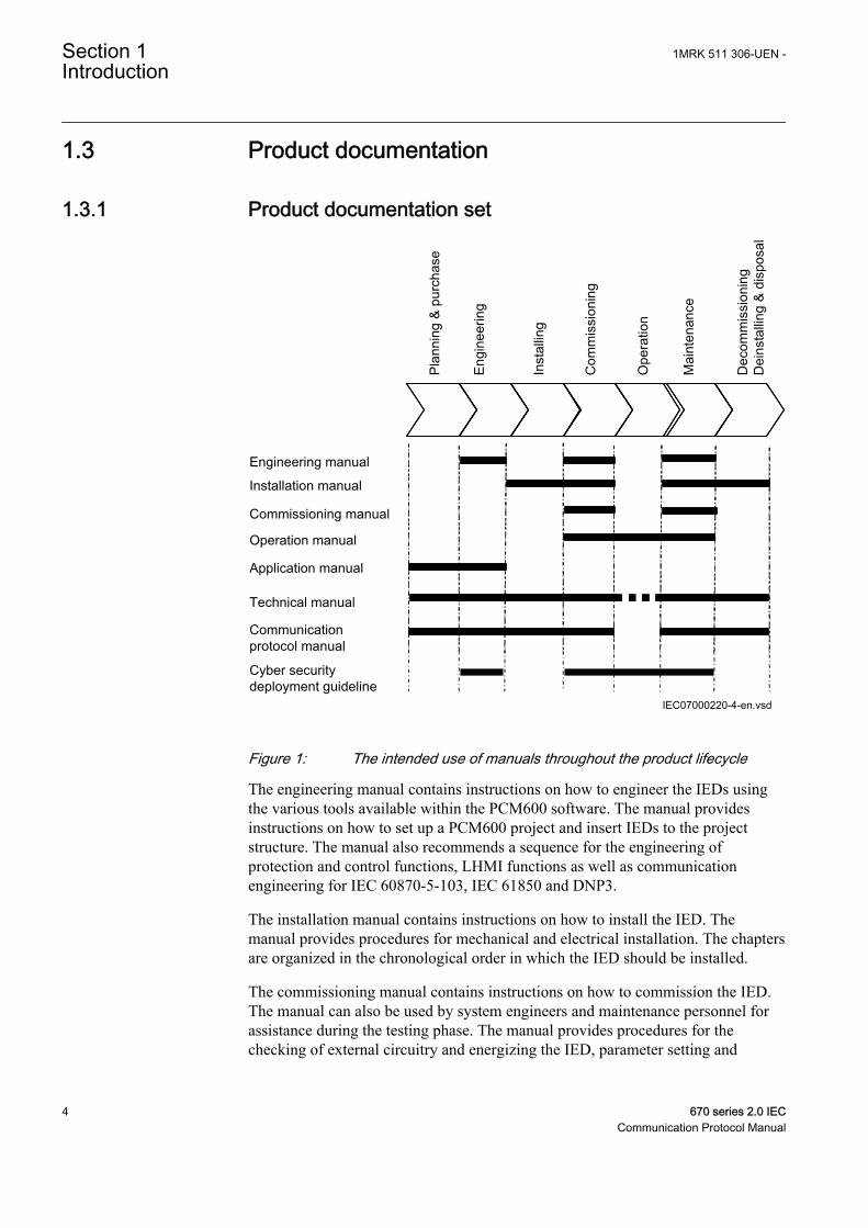
Figure 1: The intended use of manuals throughout the product lifecycle
The engineering manual contains instructions on how to engineer the IEDs usingthe various tools available within the PCM600 software. The manual providesinstructions on how to set up a PCM600 project and insert IEDs to the projectstructure. The manual also recommends a sequence for the engineering ofprotection and control functions, LHMI functions as well as communicationengineering for IEC 60870-5-103, IEC 61850 and DNP3.
The installation manual contains instructions on how to install the IED. Themanual provides procedures for mechanical and electrical installation. The chaptersare organized in the chronological order in which the IED should be installed.
The commissioning manual contains instructions on how to commission the IED.The manual can also be used by system engineers and maintenance personnel forassistance during the testing phase. The manual provides procedures for thechecking of external circuitry and energizing the IED, parameter setting and
Section 1 1MRK 511 306-UEN -Introduction
4 670 series 2.0 IECCommunication Protocol Manual
configuration as well as verifying settings by secondary injection. The manualdescribes the process of testing an IED in a substation which is not in service. Thechapters are organized in the chronological order in which the IED should becommissioned. The relevant procedures may be followed also during the serviceand maintenance activities.
The operation manual contains instructions on how to operate the IED once it hasbeen commissioned. The manual provides instructions for the monitoring,controlling and setting of the IED. The manual also describes how to identifydisturbances and how to view calculated and measured power grid data todetermine the cause of a fault.
The application manual contains application descriptions and setting guidelinessorted per function. The manual can be used to find out when and for what purposea typical protection function can be used. The manual can also provide assistancefor calculating settings.
The technical manual contains application and functionality descriptions and listsfunction blocks, logic diagrams, input and output signals, setting parameters andtechnical data, sorted per function. The manual can be used as a technical referenceduring the engineering phase, installation and commissioning phase, and duringnormal service.
The communication protocol manual describes the communication protocolssupported by the IED. The manual concentrates on the vendor-specificimplementations.
The point list manual describes the outlook and properties of the data pointsspecific to the IED. The manual should be used in conjunction with thecorresponding communication protocol manual.
The cyber security deployment guideline describes the process for handling cybersecurity when communicating with the IED. Certification, Authorization with rolebased access control, and product engineering for cyber security related events aredescribed and sorted by function. The guideline can be used as a technicalreference during the engineering phase, installation and commissioning phase, andduring normal service.
1.3.2 Document revision historyDocument revision/date History-/May 2014 First release
1MRK 511 306-UEN - Section 1Introduction
670 series 2.0 IEC 5Communication Protocol Manual
1.3.3 Related documentsDocuments related to REB670 Identify numberApplication manual 1MRK 505 302-UEN
Commissioning manual 1MRK 505 304-UEN
Product guide 1MRK 505 305-BEN
Technical manual 1MRK 505 303-UEN
Type test certificate 1MRK 505 305-TEN
Documents related to REC670 Identify numberApplication manual 1MRK 511 310-UEN
Commissioning manual 1MRK 511 312-UEN
Product guide 1MRK 511 313-BEN
Technical manual 1MRK 511 311-UEN
Type test certificate 1MRK 511 313-TEN
Documents related to RED670 Identify numberApplication manual 1MRK 505 307-UEN
Commissioning manual 1MRK 505 309-UEN
Product guide 1MRK 505 310-BEN
Technical manual 1MRK 505 308-UEN
Type test certificate 1MRK 505 310-TEN
Documents related to REG670 Identify numberApplication manual 1MRK 502 051-UEN
Commissioning manual 1MRK 502 053-UEN
Product guide 1MRK 502 054-BEN
Technical manual 1MRK 502 052-UEN
Type test certificate 1MRK 502 054-TEN
Documents related to REL670 Identify numberApplication manual 1MRK 506 338-UEN
Commissioning manual 1MRK 506 340-UEN
Product guide 1MRK 506 341-BEN
Technical manual 1MRK 506 339-UEN
Type test certificate 1MRK 506 341-TEN
Section 1 1MRK 511 306-UEN -Introduction
6 670 series 2.0 IECCommunication Protocol Manual
Documents related to RET670 Identify numberApplication manual 1MRK 504 138-UEN
Commissioning manual 1MRK 504 140-UEN
Product guide 1MRK 504 141-BEN
Technical manual 1MRK 504 139-UEN
Type test certificate 1MRK 504 141-TEN
670 series manuals Identify numberOperation manual 1MRK 500 118-UEN
Engineering manual 1MRK 511 308-UEN
Installation manual 1MRK 514 019-UEN
Communication protocol manual, IEC60870-5-103
1MRK 511 304-UEN
Communication protocol manual, IEC 61850Edition 1
1MRK 511 302-UEN
Communication protocol manual, IEC 61850Edition 2
1MRK 511 303-UEN
Communication protocol manual, LON 1MRK 511 305-UEN
Communication protocol manual, SPA 1MRK 511 306-UEN
Accessories guide 1MRK 514 012-BEN
Cyber security deployment guideline 1MRK 511 309-UEN
Connection and Installation components 1MRK 513 003-BEN
Test system, COMBITEST 1MRK 512 001-BEN
1.4 Document symbols and conventions
1.4.1 Symbols
The caution icon indicates important information or warning relatedto the concept discussed in the text. It might indicate the presenceof a hazard which could result in corruption of software or damageto equipment or property.
The information icon alerts the reader of important facts andconditions.
The tip icon indicates advice on, for example, how to design yourproject or how to use a certain function.
1MRK 511 306-UEN - Section 1Introduction
670 series 2.0 IEC 7Communication Protocol Manual

Although warning hazards are related to personal injury, it is necessary tounderstand that under certain operational conditions, operation of damagedequipment may result in degraded process performance leading to personal injuryor death. It is important that the user fully complies with all warning andcautionary notices.
1.4.2 Document conventions• Abbreviations and acronyms in this manual are spelled out in the glossary. The
glossary also contains definitions of important terms.• Push button navigation in the LHMI menu structure is presented by using the
push button icons.For example, to navigate between the options, use and .
• HMI menu paths are presented in bold.For example, select Main menu/Settings.
• LHMI messages are shown in Courier font.For example, to save the changes in non-volatile memory, select Yes andpress .
• Parameter names are shown in italics.For example, the function can be enabled and disabled with the Operation setting.
• Each function block symbol shows the available input/output signal.• the character ^ in front of an input/output signal name indicates that the
signal name may be customized using the PCM600 software.• the character * after an input/output signal name indicates that the signal
must be connected to another function block in the applicationconfiguration to achieve a valid application configuration.
• Logic diagrams describe the signal logic inside the function block and arebordered by dashed lines.• Signals in frames with a shaded area on their right hand side represent
setting parameter signals that are only settable via the PST or LHMI.• If an internal signal path cannot be drawn with a continuous line, the
suffix -int is added to the signal name to indicate where the signal startsand continues.
• Signal paths that extend beyond the logic diagram and continue inanother diagram have the suffix ”-cont.”
Section 1 1MRK 511 306-UEN -Introduction
8 670 series 2.0 IECCommunication Protocol Manual
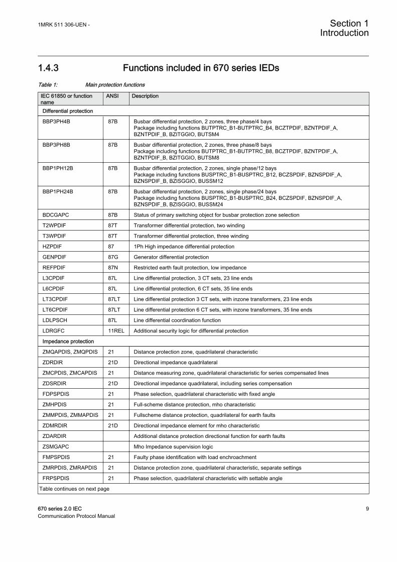
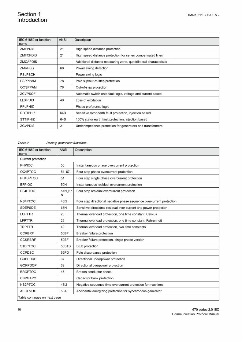
1.4.3 Functions included in 670 series IEDsTable 1: Main protection functions
IEC 61850 or functionname
ANSI Description
Differential protection
BBP3PH4B 87B Busbar differential protection, 2 zones, three phase/4 baysPackage including functions BUTPTRC_B1-BUTPTRC_B4, BCZTPDIF, BZNTPDIF_A,BZNTPDIF_B, BZITGGIO, BUTSM4
BBP3PH8B 87B Busbar differential protection, 2 zones, three phase/8 baysPackage including functions BUTPTRC_B1-BUTPTRC_B8, BCZTPDIF, BZNTPDIF_A,BZNTPDIF_B, BZITGGIO, BUTSM8
BBP1PH12B 87B Busbar differential protection, 2 zones, single phase/12 baysPackage including functions BUSPTRC_B1-BUSPTRC_B12, BCZSPDIF, BZNSPDIF_A,BZNSPDIF_B, BZISGGIO, BUSSM12
BBP1PH24B 87B Busbar differential protection, 2 zones, single phase/24 baysPackage including functions BUSPTRC_B1-BUSPTRC_B24, BCZSPDIF, BZNSPDIF_A,BZNSPDIF_B, BZISGGIO, BUSSM24
BDCGAPC 87B Status of primary switching object for busbar protection zone selection
T2WPDIF 87T Transformer differential protection, two winding
T3WPDIF 87T Transformer differential protection, three winding
HZPDIF 87 1Ph High impedance differential protection
GENPDIF 87G Generator differential protection
REFPDIF 87N Restricted earth fault protection, low impedance
L3CPDIF 87L Line differential protection, 3 CT sets, 23 line ends
L6CPDIF 87L Line differential protection, 6 CT sets, 35 line ends
LT3CPDIF 87LT Line differential protection 3 CT sets, with inzone transformers, 23 line ends
LT6CPDIF 87LT Line differential protection 6 CT sets, with inzone transformers, 35 line ends
LDLPSCH 87L Line differential coordination function
LDRGFC 11REL Additional security logic for differential protection
Impedance protection
ZMQAPDIS, ZMQPDIS 21 Distance protection zone, quadrilateral characteristic
ZDRDIR 21D Directional impedance quadrilateral
ZMCPDIS, ZMCAPDIS 21 Distance measuring zone, quadrilateral characteristic for series compensated lines
ZDSRDIR 21D Directional impedance quadrilateral, including series compensation
FDPSPDIS 21 Phase selection, quadrilateral characteristic with fixed angle
ZMHPDIS 21 Full-scheme distance protection, mho characteristic
ZMMPDIS, ZMMAPDIS 21 Fullscheme distance protection, quadrilateral for earth faults
ZDMRDIR 21D Directional impedance element for mho characteristic
ZDARDIR Additional distance protection directional function for earth faults
ZSMGAPC Mho Impedance supervision logic
FMPSPDIS 21 Faulty phase identification with load enchroachment
ZMRPDIS, ZMRAPDIS 21 Distance protection zone, quadrilateral characteristic, separate settings
FRPSPDIS 21 Phase selection, quadrilateral characteristic with settable angle
Table continues on next page
1MRK 511 306-UEN - Section 1Introduction
670 series 2.0 IEC 9Communication Protocol Manual
IEC 61850 or functionname
ANSI Description
ZMFPDIS 21 High speed distance protection
ZMFCPDIS 21 High speed distance protection for series compensated lines
ZMCAPDIS Additional distance measuring zone, quadrilateral characteristic
ZMRPSB 68 Power swing detection
PSLPSCH Power swing logic
PSPPPAM 78 Pole slip/out-of-step protection
OOSPPAM 78 Out-of-step protection
ZCVPSOF Automatic switch onto fault logic, voltage and current based
LEXPDIS 40 Loss of excitation
PPLPHIZ Phase preference logic
ROTIPHIZ 64R Sensitive rotor earth fault protection, injection based
STTIPHIZ 64S 100% stator earth fault protection, injection based
ZGVPDIS 21 Underimpedance protection for generators and transformers
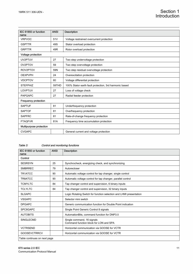
Table 2: Backup protection functions
IEC 61850 or functionname
ANSI Description
Current protection
PHPIOC 50 Instantaneous phase overcurrent protection
OC4PTOC 51_67 Four step phase overcurrent protection
PH4SPTOC 51 Four step single phase overcurrent protection
EFPIOC 50N Instantaneous residual overcurrent protection
EF4PTOC 51N_67N
Four step residual overcurrent protection
NS4PTOC 46I2 Four step directional negative phase sequence overcurrent protection
SDEPSDE 67N Sensitive directional residual over current and power protection
LCPTTR 26 Thermal overload protection, one time constant, Celsius
LFPTTR 26 Thermal overload protection, one time constant, Fahrenheit
TRPTTR 49 Thermal overload protection, two time constants
CCRBRF 50BF Breaker failure protection
CCSRBRF 50BF Breaker failure protection, single phase version
STBPTOC 50STB Stub protection
CCPDSC 52PD Pole discordance protection
GUPPDUP 37 Directional underpower protection
GOPPDOP 32 Directional overpower protection
BRCPTOC 46 Broken conductor check
CBPGAPC Capacitor bank protection
NS2PTOC 46I2 Negative sequence time overcurrent protection for machines
AEGPVOC 50AE Accidental energizing protection for synchronous generator
Table continues on next page
Section 1 1MRK 511 306-UEN -Introduction
10 670 series 2.0 IECCommunication Protocol Manual
IEC 61850 or functionname
ANSI Description
VRPVOC 51V Voltage restrained overcurrent protection
GSPTTR 49S Stator overload protection
GRPTTR 49R Rotor overload protection
Voltage protection
UV2PTUV 27 Two step undervoltage protection
OV2PTOV 59 Two step overvoltage protection
ROV2PTOV 59N Two step residual overvoltage protection
OEXPVPH 24 Overexcitation protection
VDCPTOV 60 Voltage differential protection
STEFPHIZ 59THD 100% Stator earth fault protection, 3rd harmonic based
LOVPTUV 27 Loss of voltage check
PAPGAPC 27 Radial feeder protection
Frequency protection
SAPTUF 81 Underfrequency protection
SAPTOF 81 Overfrequency protection
SAPFRC 81 Rate-of-change frequency protection
FTAQFVR 81A Frequency time accumulation protection
Multipurpose protection
CVGAPC General current and voltage protection
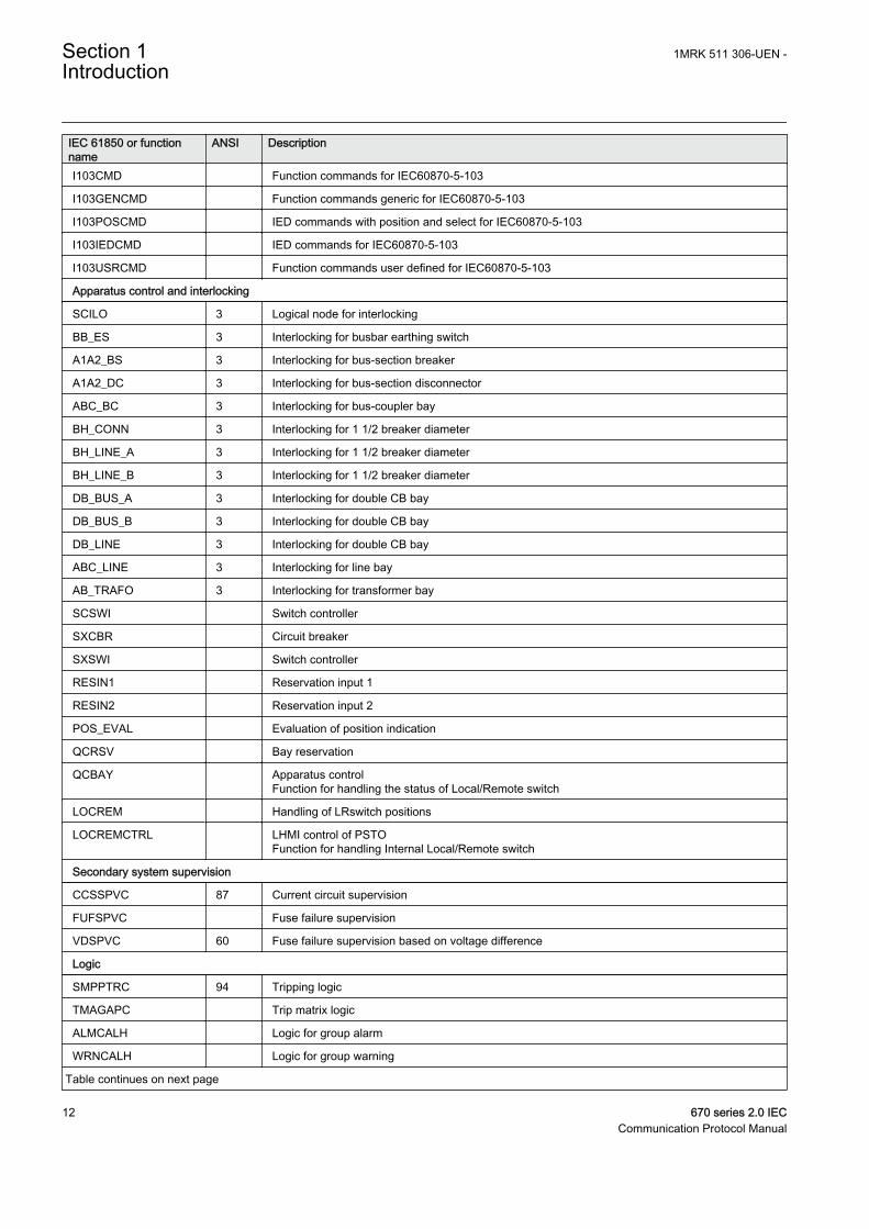
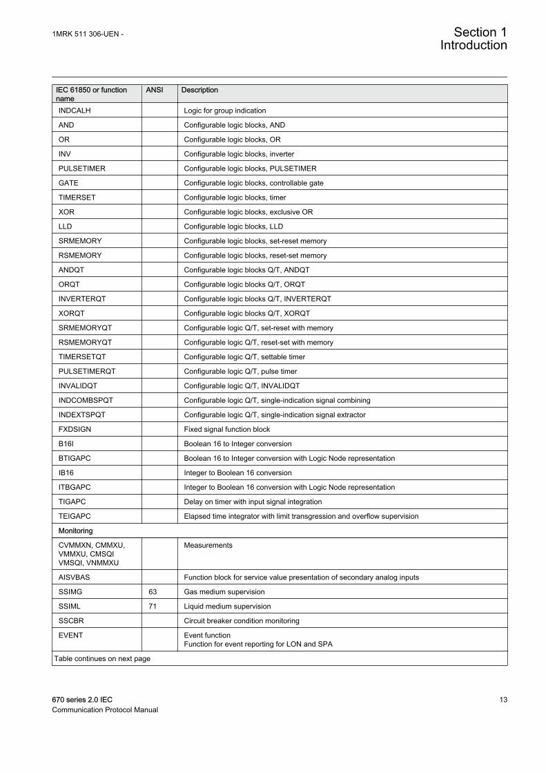
Table 3: Control and monitoring functions
IEC 61850 or functionname
ANSI Description
Control
SESRSYN 25 Synchrocheck, energizing check, and synchronizing
SMBRREC 79 Autorecloser
TR1ATCC 90 Automatic voltage control for tap changer, single control
TR8ATCC 90 Automatic voltage control for tap changer, parallel control
TCMYLTC 84 Tap changer control and supervision, 6 binary inputs
TCLYLTC 84 Tap changer control and supervision, 32 binary inputs
SLGAPC Logic Rotating Switch for function selection and LHMI presentation
VSGAPC Selector mini switch
DPGAPC Generic communication function for Double Point indication
SPC8GAPC Single Point Generic Control 8 signals
AUTOBITS AutomationBits, command function for DNP3.0
SINGLECMD Single command, 16 signalsCommand function block for LON and SPA
VCTRSEND Horizontal communication via GOOSE for VCTR
GOOSEVCTRRCV Horizontal communication via GOOSE for VCTR
Table continues on next page
1MRK 511 306-UEN - Section 1Introduction
670 series 2.0 IEC 11Communication Protocol Manual
IEC 61850 or functionname
ANSI Description
I103CMD Function commands for IEC60870-5-103
I103GENCMD Function commands generic for IEC60870-5-103
I103POSCMD IED commands with position and select for IEC60870-5-103
I103IEDCMD IED commands for IEC60870-5-103
I103USRCMD Function commands user defined for IEC60870-5-103
Apparatus control and interlocking
SCILO 3 Logical node for interlocking
BB_ES 3 Interlocking for busbar earthing switch
A1A2_BS 3 Interlocking for bus-section breaker
A1A2_DC 3 Interlocking for bus-section disconnector
ABC_BC 3 Interlocking for bus-coupler bay
BH_CONN 3 Interlocking for 1 1/2 breaker diameter
BH_LINE_A 3 Interlocking for 1 1/2 breaker diameter
BH_LINE_B 3 Interlocking for 1 1/2 breaker diameter
DB_BUS_A 3 Interlocking for double CB bay
DB_BUS_B 3 Interlocking for double CB bay
DB_LINE 3 Interlocking for double CB bay
ABC_LINE 3 Interlocking for line bay
AB_TRAFO 3 Interlocking for transformer bay
SCSWI Switch controller
SXCBR Circuit breaker
SXSWI Switch controller
RESIN1 Reservation input 1
RESIN2 Reservation input 2
POS_EVAL Evaluation of position indication
QCRSV Bay reservation
QCBAY Apparatus controlFunction for handling the status of Local/Remote switch
LOCREM Handling of LRswitch positions
LOCREMCTRL LHMI control of PSTOFunction for handling Internal Local/Remote switch
Secondary system supervision
CCSSPVC 87 Current circuit supervision
FUFSPVC Fuse failure supervision
VDSPVC 60 Fuse failure supervision based on voltage difference
Logic
SMPPTRC 94 Tripping logic
TMAGAPC Trip matrix logic
ALMCALH Logic for group alarm
WRNCALH Logic for group warning
Table continues on next page
Section 1 1MRK 511 306-UEN -Introduction
12 670 series 2.0 IECCommunication Protocol Manual
IEC 61850 or functionname
ANSI Description
INDCALH Logic for group indication
AND Configurable logic blocks, AND
OR Configurable logic blocks, OR
INV Configurable logic blocks, inverter
PULSETIMER Configurable logic blocks, PULSETIMER
GATE Configurable logic blocks, controllable gate
TIMERSET Configurable logic blocks, timer
XOR Configurable logic blocks, exclusive OR
LLD Configurable logic blocks, LLD
SRMEMORY Configurable logic blocks, set-reset memory
RSMEMORY Configurable logic blocks, reset-set memory
ANDQT Configurable logic blocks Q/T, ANDQT
ORQT Configurable logic blocks Q/T, ORQT
INVERTERQT Configurable logic blocks Q/T, INVERTERQT
XORQT Configurable logic blocks Q/T, XORQT
SRMEMORYQT Configurable logic Q/T, set-reset with memory
RSMEMORYQT Configurable logic Q/T, reset-set with memory
TIMERSETQT Configurable logic Q/T, settable timer
PULSETIMERQT Configurable logic Q/T, pulse timer
INVALIDQT Configurable logic Q/T, INVALIDQT
INDCOMBSPQT Configurable logic Q/T, single-indication signal combining
INDEXTSPQT Configurable logic Q/T, single-indication signal extractor
FXDSIGN Fixed signal function block
B16I Boolean 16 to Integer conversion
BTIGAPC Boolean 16 to Integer conversion with Logic Node representation
IB16 Integer to Boolean 16 conversion
ITBGAPC Integer to Boolean 16 conversion with Logic Node representation
TIGAPC Delay on timer with input signal integration
TEIGAPC Elapsed time integrator with limit transgression and overflow supervision
Monitoring
CVMMXN, CMMXU,VMMXU, CMSQIVMSQI, VNMMXU
Measurements
AISVBAS Function block for service value presentation of secondary analog inputs
SSIMG 63 Gas medium supervision
SSIML 71 Liquid medium supervision
SSCBR Circuit breaker condition monitoring
EVENT Event functionFunction for event reporting for LON and SPA
Table continues on next page
1MRK 511 306-UEN - Section 1Introduction
670 series 2.0 IEC 13Communication Protocol Manual
IEC 61850 or functionname
ANSI Description
DRPRDRE, A1RADR-A4RADR, B1RBDR-B6RBDR
Disturbance report
SPGAPC Generic communication function for Single Point indication
SP16GAPC Generic communication function for Single Point indication 16 inputs
MVGAPC Generic communication function for Measured Value
BINSTATREP Logical signal status report
RANGE_XP Measured value expander block
LMBRFLO Fault locator
I103MEAS Measurands for IEC60870-5-103
I103MEASUSR Measurands user defined signals for IEC60870-5-103
I103AR Function status auto-recloser for IEC60870-5-103
I103EF Function status earth-fault for IEC60870-5-103
I103FLTPROT Function status fault protection for IEC60870-5-103
I103IED IED status for IEC60870-5-103
I103SUPERV Supervison status for IEC60870-5-103
I103USRDEF Status for user defiend signals for IEC60870-5-103
L4UFCNT Event counter with limit supervision
Metering
PCFCNT Pulse-counter logic
ETPMMTR Function for energy calculation and demand handling
System protection and control
SMAIHPAC Multipurpose filter
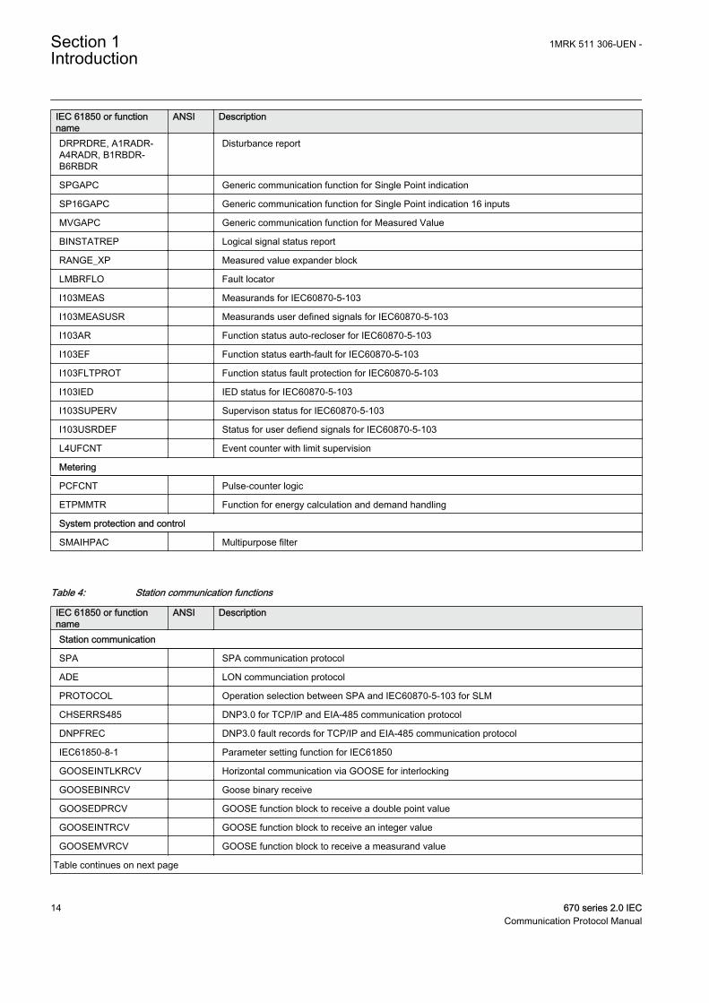
Table 4: Station communication functions
IEC 61850 or functionname
ANSI Description
Station communication
SPA SPA communication protocol
ADE LON communciation protocol
PROTOCOL Operation selection between SPA and IEC60870-5-103 for SLM
CHSERRS485 DNP3.0 for TCP/IP and EIA-485 communication protocol
DNPFREC DNP3.0 fault records for TCP/IP and EIA-485 communication protocol
IEC61850-8-1 Parameter setting function for IEC61850
GOOSEINTLKRCV Horizontal communication via GOOSE for interlocking
GOOSEBINRCV Goose binary receive
GOOSEDPRCV GOOSE function block to receive a double point value
GOOSEINTRCV GOOSE function block to receive an integer value
GOOSEMVRCV GOOSE function block to receive a measurand value
Table continues on next page
Section 1 1MRK 511 306-UEN -Introduction
14 670 series 2.0 IECCommunication Protocol Manual
IEC 61850 or functionname
ANSI Description
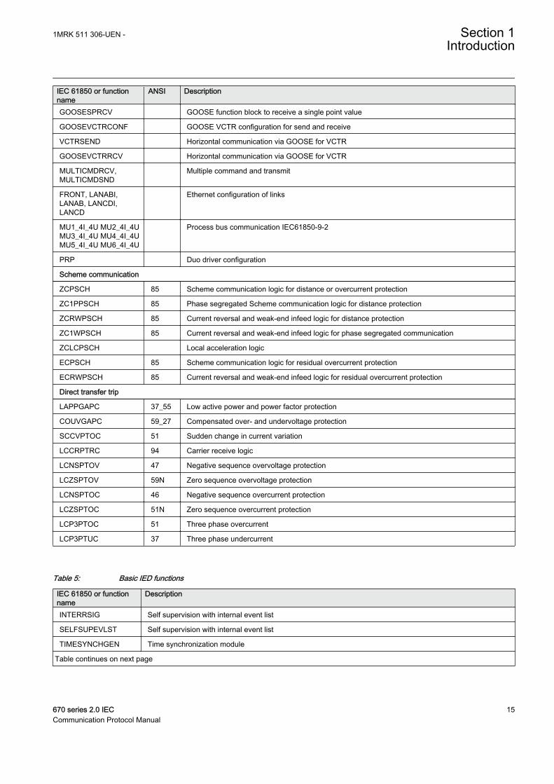
GOOSESPRCV GOOSE function block to receive a single point value
GOOSEVCTRCONF GOOSE VCTR configuration for send and receive
VCTRSEND Horizontal communication via GOOSE for VCTR
GOOSEVCTRRCV Horizontal communication via GOOSE for VCTR
MULTICMDRCV,MULTICMDSND
Multiple command and transmit
FRONT, LANABI,LANAB, LANCDI,LANCD
Ethernet configuration of links
MU1_4I_4U MU2_4I_4UMU3_4I_4U MU4_4I_4UMU5_4I_4U MU6_4I_4U
Process bus communication IEC61850-9-2
PRP Duo driver configuration
Scheme communication
ZCPSCH 85 Scheme communication logic for distance or overcurrent protection
ZC1PPSCH 85 Phase segregated Scheme communication logic for distance protection
ZCRWPSCH 85 Current reversal and weak-end infeed logic for distance protection
ZC1WPSCH 85 Current reversal and weak-end infeed logic for phase segregated communication
ZCLCPSCH Local acceleration logic
ECPSCH 85 Scheme communication logic for residual overcurrent protection
ECRWPSCH 85 Current reversal and weak-end infeed logic for residual overcurrent protection
Direct transfer trip
LAPPGAPC 37_55 Low active power and power factor protection
COUVGAPC 59_27 Compensated over- and undervoltage protection
SCCVPTOC 51 Sudden change in current variation
LCCRPTRC 94 Carrier receive logic
LCNSPTOV 47 Negative sequence overvoltage protection
LCZSPTOV 59N Zero sequence overvoltage protection
LCNSPTOC 46 Negative sequence overcurrent protection
LCZSPTOC 51N Zero sequence overcurrent protection
LCP3PTOC 51 Three phase overcurrent
LCP3PTUC 37 Three phase undercurrent
Table 5: Basic IED functions
IEC 61850 or functionname
Description
INTERRSIG Self supervision with internal event list
SELFSUPEVLST Self supervision with internal event list
TIMESYNCHGEN Time synchronization module
Table continues on next page
1MRK 511 306-UEN - Section 1Introduction
670 series 2.0 IEC 15Communication Protocol Manual

IEC 61850 or functionname
Description
SYNCHBIN,SYNCHCAN,SYNCHCMPPS,SYNCHLON,SYNCHPPH,SYNCHPPS,SYNCHSNTP,SYNCHSPA,SYNCHCMPPS
Time synchronization
TIMEZONE Time synchronization
DSTBEGIN,DSTENABLE, DSTEND
GPS time synchronization module
IRIG-B Time synchronization
SETGRPS Number of setting groups
ACTVGRP Parameter setting groups
TESTMODE Test mode functionality
CHNGLCK Change lock function
LONGEN Misc Base Common
SMBI Signal matrix for binary inputs
SMBO Signal matrix for binary outputs
SMMI Signal matrix for mA inputs
SMAI1 - SMAI20 Signal matrix for analog inputs
3PHSUM Summation block 3 phase
ATHSTAT Authority status
ATHCHCK Authority check
AUTHMAN Authority management
FTPACCS FTP access with password
SPACOMMMAP SPA communication mapping
SPATD Date and time via SPA protocol
DOSFRNT Denial of service, frame rate control for front port
DOSLANAB Denial of service, frame rate control for OEM port AB
DOSLANCD Denial of service, frame rate control for OEM port CD
DOSSCKT Denial of service, socket flow control
GBASVAL Global base values for settings
PRIMVAL Primary system values
ALTMS Time master supervision
ALTIM Time management
ALTRK Service tracking
ACTIVLOG Activity logging parameters
FSTACCS Field service tool access via SPA protocol over ethernet communication
PCMACCS IED Configuration Protocol
SECALARM Component for mapping security events on protocols such as DNP3 and IEC103
Table continues on next page
Section 1 1MRK 511 306-UEN -Introduction
16 670 series 2.0 IECCommunication Protocol Manual
IEC 61850 or functionname
Description
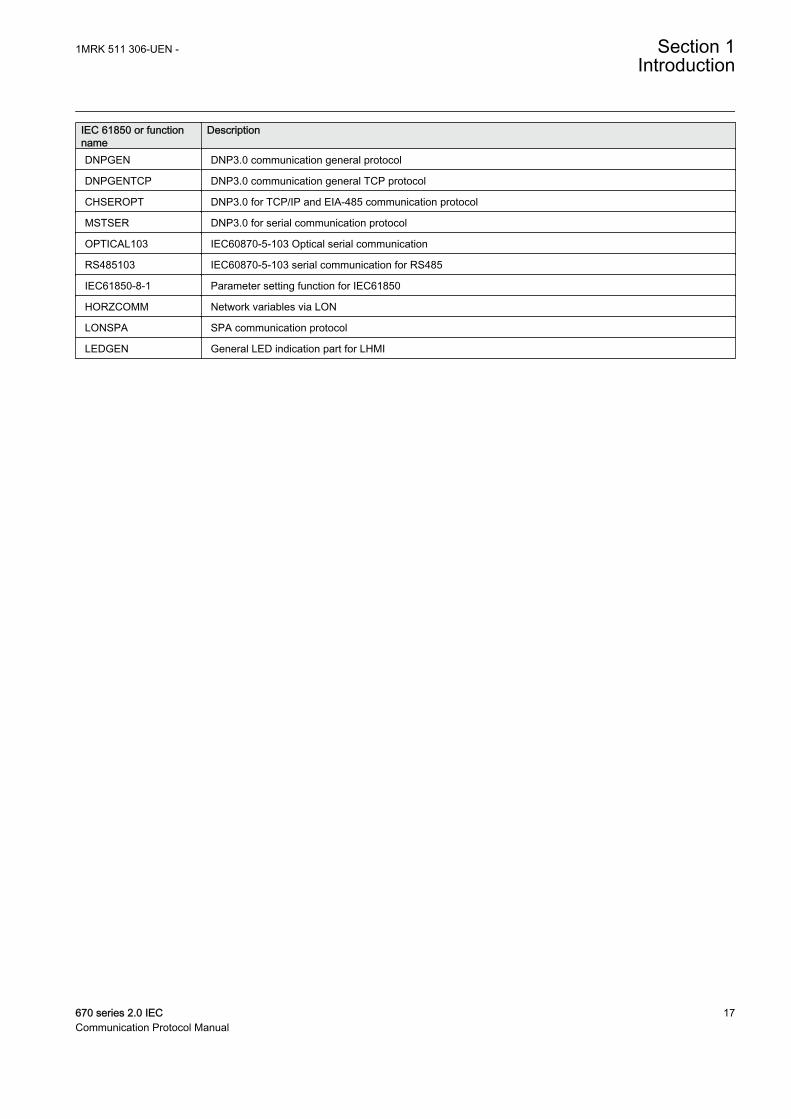
DNPGEN DNP3.0 communication general protocol
DNPGENTCP DNP3.0 communication general TCP protocol
CHSEROPT DNP3.0 for TCP/IP and EIA-485 communication protocol
MSTSER DNP3.0 for serial communication protocol
OPTICAL103 IEC60870-5-103 Optical serial communication
RS485103 IEC60870-5-103 serial communication for RS485
IEC61850-8-1 Parameter setting function for IEC61850
HORZCOMM Network variables via LON
LONSPA SPA communication protocol
LEDGEN General LED indication part for LHMI
1MRK 511 306-UEN - Section 1Introduction
670 series 2.0 IEC 17Communication Protocol Manual

18
Section 2 SPA application
2.1 SPA communication protocol
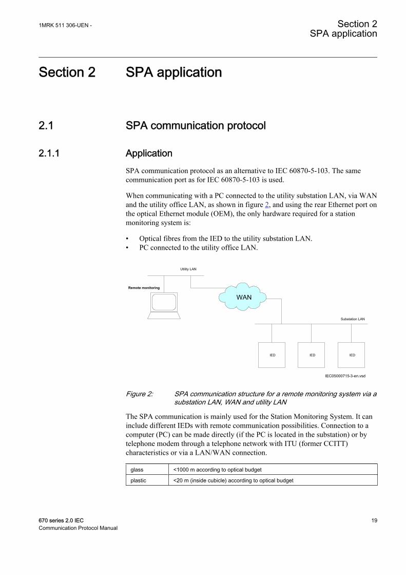
2.1.1 ApplicationSPA communication protocol as an alternative to IEC 60870-5-103. The samecommunication port as for IEC 60870-5-103 is used.
When communicating with a PC connected to the utility substation LAN, via WANand the utility office LAN, as shown in figure 2, and using the rear Ethernet port onthe optical Ethernet module (OEM), the only hardware required for a stationmonitoring system is:
• Optical fibres from the IED to the utility substation LAN.• PC connected to the utility office LAN.
IED IEDIED
Substation LAN
IEC05000715-3-en.vsd
Remote monitoring
Utility LAN
WAN
IEC05000715 V3 EN
Figure 2: SPA communication structure for a remote monitoring system via asubstation LAN, WAN and utility LAN
The SPA communication is mainly used for the Station Monitoring System. It caninclude different IEDs with remote communication possibilities. Connection to acomputer (PC) can be made directly (if the PC is located in the substation) or bytelephone modem through a telephone network with ITU (former CCITT)characteristics or via a LAN/WAN connection.
glass <1000 m according to optical budget
plastic <20 m (inside cubicle) according to optical budget
1MRK 511 306-UEN - Section 2SPA application
670 series 2.0 IEC 19Communication Protocol Manual
FunctionalityThe SPA protocol V2.5 is an ASCII-based protocol for serial communication. Thecommunication is based on a master-slave principle, where the IED is a slave andthe PC is the master. Only one master can be applied on each fibre optic loop. Aprogram is required in the master computer for interpretation of the SPA-bus codesand for translation of the data that should be sent to the IED.
For the specification of the SPA protocol V2.5, refer to SPA-bus CommunicationProtocol V2.5.
2.1.2 Setting guidelinesThe setting parameters for the SPA communication are set via the local HMI.
SPA, IEC 60870-5-103 and DNP3 uses the same rear communication port. Set theparameter Operation, under Main menu /Settings /General settings /Communication /SLM configuration /Rear optical SPA-IEC-DNP port /Protocol selection to the selected protocol.
When the communication protocols have been selected, the IED is automaticallyrestarted.
The most important settings in the IED for SPA communication are the slavenumber and baud rate (communication speed). These settings are absolutelyessential for all communication contact to the IED.
These settings can only be done on the local HMI for rear channel communicationand for front channel communication.
The slave number can be set to any value from 1 to 899, as long as the slavenumber is unique within the used SPA loop.
The baud rate, which is the communication speed, can be set to between 300 and38400 baud. Refer to technical data to determine the rated communication speedfor the selected communication interfaces. The baud rate should be the same for thewhole station, although different baud rates in a loop are possible. If different baudrates in the same fibre optical loop or RS485 network are used, consider this whenmaking the communication setup in the communication master, the PC.
For local fibre optic communication, 19200 or 38400 baud is the normal setting. Iftelephone communication is used, the communication speed depends on the qualityof the connection and on the type of modem used. But remember that the IED doesnot adapt its speed to the actual communication conditions, because the speed is seton the local HMI.
Section 2 1MRK 511 306-UEN -SPA application
20 670 series 2.0 IECCommunication Protocol Manual
Section 3 SPA operation principle
3.1 Operation principle
The SPA bus uses an asynchronous serial communications protocol (1 start bit, 7data bits + even parity, 1 stop bit) with data transfer rate up to 38400 bit/s. Formore information on recommended baud rate for each type of IED, refer toTechnical reference manual. Messages on the bus consist of ASCII characters.
3.1.1.1 Introduction of SPA protocol
The basic construction of the protocol assumes that the slave has no self-initiatedneed to talk to the master but the master is aware of the data contained in the slavesand, consequently, can request required data. In addition, the master can send datato the slave. Requesting by the master can be performed either by sequencedpolling (for example, for event information) or only on demand.
The master requests slave information using request messages and sendsinformation to the slave in write messages. Furthermore, the master can send allslaves in common a broadcast message containing time or other data. The inactivestate of bus transmit and receive lines is a logical "1".
3.1.1.2 SPA protocol
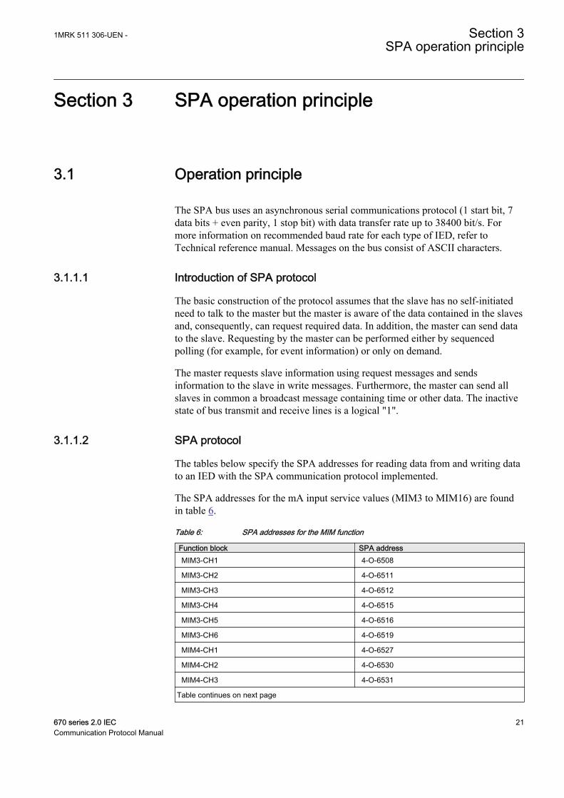
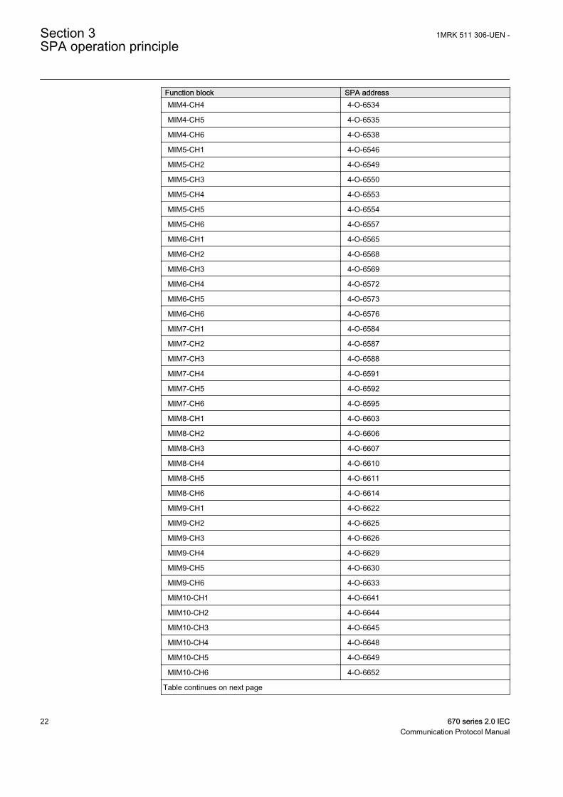
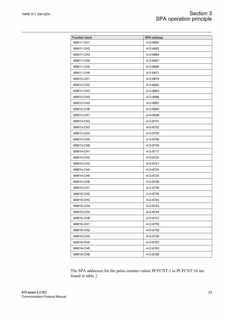
The tables below specify the SPA addresses for reading data from and writing datato an IED with the SPA communication protocol implemented.
The SPA addresses for the mA input service values (MIM3 to MIM16) are foundin table 6.
Table 6: SPA addresses for the MIM function
Function block SPA addressMIM3-CH1 4-O-6508
MIM3-CH2 4-O-6511
MIM3-CH3 4-O-6512
MIM3-CH4 4-O-6515
MIM3-CH5 4-O-6516
MIM3-CH6 4-O-6519
MIM4-CH1 4-O-6527
MIM4-CH2 4-O-6530
MIM4-CH3 4-O-6531
Table continues on next page
1MRK 511 306-UEN - Section 3SPA operation principle
670 series 2.0 IEC 21Communication Protocol Manual
Function block SPA addressMIM4-CH4 4-O-6534
MIM4-CH5 4-O-6535
MIM4-CH6 4-O-6538
MIM5-CH1 4-O-6546
MIM5-CH2 4-O-6549
MIM5-CH3 4-O-6550
MIM5-CH4 4-O-6553
MIM5-CH5 4-O-6554
MIM5-CH6 4-O-6557
MIM6-CH1 4-O-6565
MIM6-CH2 4-O-6568
MIM6-CH3 4-O-6569
MIM6-CH4 4-O-6572
MIM6-CH5 4-O-6573
MIM6-CH6 4-O-6576
MIM7-CH1 4-O-6584
MIM7-CH2 4-O-6587
MIM7-CH3 4-O-6588
MIM7-CH4 4-O-6591
MIM7-CH5 4-O-6592
MIM7-CH6 4-O-6595
MIM8-CH1 4-O-6603
MIM8-CH2 4-O-6606
MIM8-CH3 4-O-6607
MIM8-CH4 4-O-6610
MIM8-CH5 4-O-6611
MIM8-CH6 4-O-6614
MIM9-CH1 4-O-6622
MIM9-CH2 4-O-6625
MIM9-CH3 4-O-6626
MIM9-CH4 4-O-6629
MIM9-CH5 4-O-6630
MIM9-CH6 4-O-6633
MIM10-CH1 4-O-6641
MIM10-CH2 4-O-6644
MIM10-CH3 4-O-6645
MIM10-CH4 4-O-6648
MIM10-CH5 4-O-6649
MIM10-CH6 4-O-6652
Table continues on next page
Section 3 1MRK 511 306-UEN -SPA operation principle
22 670 series 2.0 IECCommunication Protocol Manual
Function block SPA addressMIM11-CH1 4-O-6660
MIM11-CH2 4-O-6663
MIM11-CH3 4-O-6664
MIM11-CH4 4-O-6667
MIM11-CH5 4-O-6668
MIM11-CH6 4-O-6671
MIM12-CH1 4-O-6679
MIM12-CH2 4-O-6682
MIM12-CH3 4-O-6683
MIM12-CH4 4-O-6686
MIM12-CH5 4-O-6687
MIM12-CH6 4-O-6690
MIM13-CH1 4-O-6698
MIM13-CH2 4-O-6701
MIM13-CH3 4-O-6702
MIM13-CH4 4-O-6705
MIM13-CH5 4-O-6706
MIM13-CH6 4-O-6709
MIM14-CH1 4-O-6717
MIM14-CH2 4-O-6720
MIM14-CH3 4-O-6721
MIM14-CH4 4-O-6724
MIM14-CH5 4-O-6725
MIM14-CH6 4-O-6728
MIM15-CH1 4-O-6736
MIM15-CH2 4-O-6739
MIM15-CH3 4-O-6740
MIM15-CH4 4-O-6743
MIM15-CH5 4-O-6744
MIM15-CH6 4-O-6747
MIM16-CH1 4-O-6755
MIM16-CH2 4-O-6758
MIM16-CH3 4-O-6759
MIM16-CH4 4-O-6762
MIM16-CH5 4-O-6763
MIM16-CH6 4-O-6766
The SPA addresses for the pulse counter values PCFCNT:1 to PCFCNT:16 arefound in table 7.
1MRK 511 306-UEN - Section 3SPA operation principle
670 series 2.0 IEC 23Communication Protocol Manual
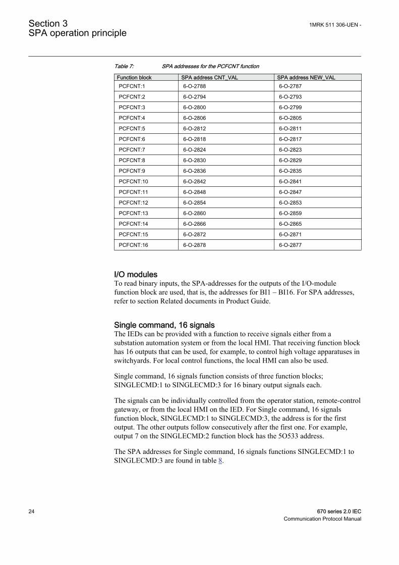
Table 7: SPA addresses for the PCFCNT function
Function block SPA address CNT_VAL SPA address NEW_VALPCFCNT:1 6-O-2788 6-O-2787
PCFCNT:2 6-O-2794 6-O-2793
PCFCNT:3 6-O-2800 6-O-2799
PCFCNT:4 6-O-2806 6-O-2805
PCFCNT:5 6-O-2812 6-O-2811
PCFCNT:6 6-O-2818 6-O-2817
PCFCNT:7 6-O-2824 6-O-2823
PCFCNT:8 6-O-2830 6-O-2829
PCFCNT:9 6-O-2836 6-O-2835
PCFCNT:10 6-O-2842 6-O-2841
PCFCNT:11 6-O-2848 6-O-2847
PCFCNT:12 6-O-2854 6-O-2853
PCFCNT:13 6-O-2860 6-O-2859
PCFCNT:14 6-O-2866 6-O-2865
PCFCNT:15 6-O-2872 6-O-2871
PCFCNT:16 6-O-2878 6-O-2877
I/O modulesTo read binary inputs, the SPA-addresses for the outputs of the I/O-modulefunction block are used, that is, the addresses for BI1 – BI16. For SPA addresses,refer to section Related documents in Product Guide.
Single command, 16 signalsThe IEDs can be provided with a function to receive signals either from asubstation automation system or from the local HMI. That receiving function blockhas 16 outputs that can be used, for example, to control high voltage apparatuses inswitchyards. For local control functions, the local HMI can also be used.
Single command, 16 signals function consists of three function blocks;SINGLECMD:1 to SINGLECMD:3 for 16 binary output signals each.
The signals can be individually controlled from the operator station, remote-controlgateway, or from the local HMI on the IED. For Single command, 16 signalsfunction block, SINGLECMD:1 to SINGLECMD:3, the address is for the firstoutput. The other outputs follow consecutively after the first one. For example,output 7 on the SINGLECMD:2 function block has the 5O533 address.
The SPA addresses for Single command, 16 signals functions SINGLECMD:1 toSINGLECMD:3 are found in table 8.
Section 3 1MRK 511 306-UEN -SPA operation principle
24 670 series 2.0 IECCommunication Protocol Manual
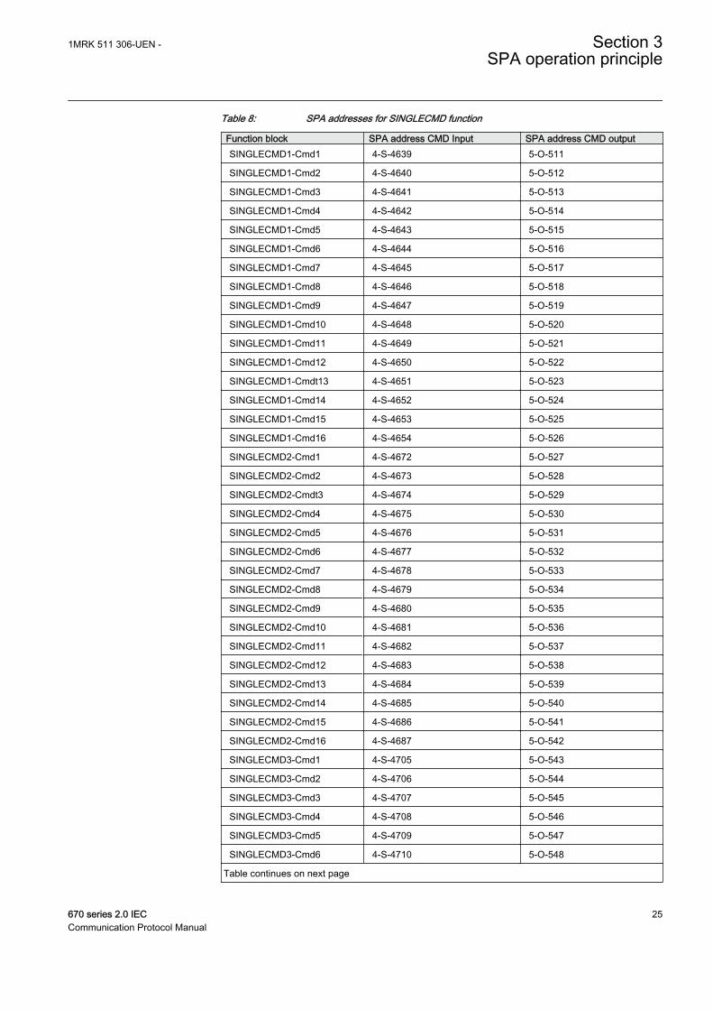
Table 8: SPA addresses for SINGLECMD function
Function block SPA address CMD Input SPA address CMD outputSINGLECMD1-Cmd1 4-S-4639 5-O-511
SINGLECMD1-Cmd2 4-S-4640 5-O-512
SINGLECMD1-Cmd3 4-S-4641 5-O-513
SINGLECMD1-Cmd4 4-S-4642 5-O-514
SINGLECMD1-Cmd5 4-S-4643 5-O-515
SINGLECMD1-Cmd6 4-S-4644 5-O-516
SINGLECMD1-Cmd7 4-S-4645 5-O-517
SINGLECMD1-Cmd8 4-S-4646 5-O-518
SINGLECMD1-Cmd9 4-S-4647 5-O-519
SINGLECMD1-Cmd10 4-S-4648 5-O-520
SINGLECMD1-Cmd11 4-S-4649 5-O-521
SINGLECMD1-Cmd12 4-S-4650 5-O-522
SINGLECMD1-Cmdt13 4-S-4651 5-O-523
SINGLECMD1-Cmd14 4-S-4652 5-O-524
SINGLECMD1-Cmd15 4-S-4653 5-O-525
SINGLECMD1-Cmd16 4-S-4654 5-O-526
SINGLECMD2-Cmd1 4-S-4672 5-O-527
SINGLECMD2-Cmd2 4-S-4673 5-O-528
SINGLECMD2-Cmdt3 4-S-4674 5-O-529
SINGLECMD2-Cmd4 4-S-4675 5-O-530
SINGLECMD2-Cmd5 4-S-4676 5-O-531
SINGLECMD2-Cmd6 4-S-4677 5-O-532
SINGLECMD2-Cmd7 4-S-4678 5-O-533
SINGLECMD2-Cmd8 4-S-4679 5-O-534
SINGLECMD2-Cmd9 4-S-4680 5-O-535
SINGLECMD2-Cmd10 4-S-4681 5-O-536
SINGLECMD2-Cmd11 4-S-4682 5-O-537
SINGLECMD2-Cmd12 4-S-4683 5-O-538
SINGLECMD2-Cmd13 4-S-4684 5-O-539
SINGLECMD2-Cmd14 4-S-4685 5-O-540
SINGLECMD2-Cmd15 4-S-4686 5-O-541
SINGLECMD2-Cmd16 4-S-4687 5-O-542
SINGLECMD3-Cmd1 4-S-4705 5-O-543
SINGLECMD3-Cmd2 4-S-4706 5-O-544
SINGLECMD3-Cmd3 4-S-4707 5-O-545
SINGLECMD3-Cmd4 4-S-4708 5-O-546
SINGLECMD3-Cmd5 4-S-4709 5-O-547
SINGLECMD3-Cmd6 4-S-4710 5-O-548
Table continues on next page
1MRK 511 306-UEN - Section 3SPA operation principle
670 series 2.0 IEC 25Communication Protocol Manual
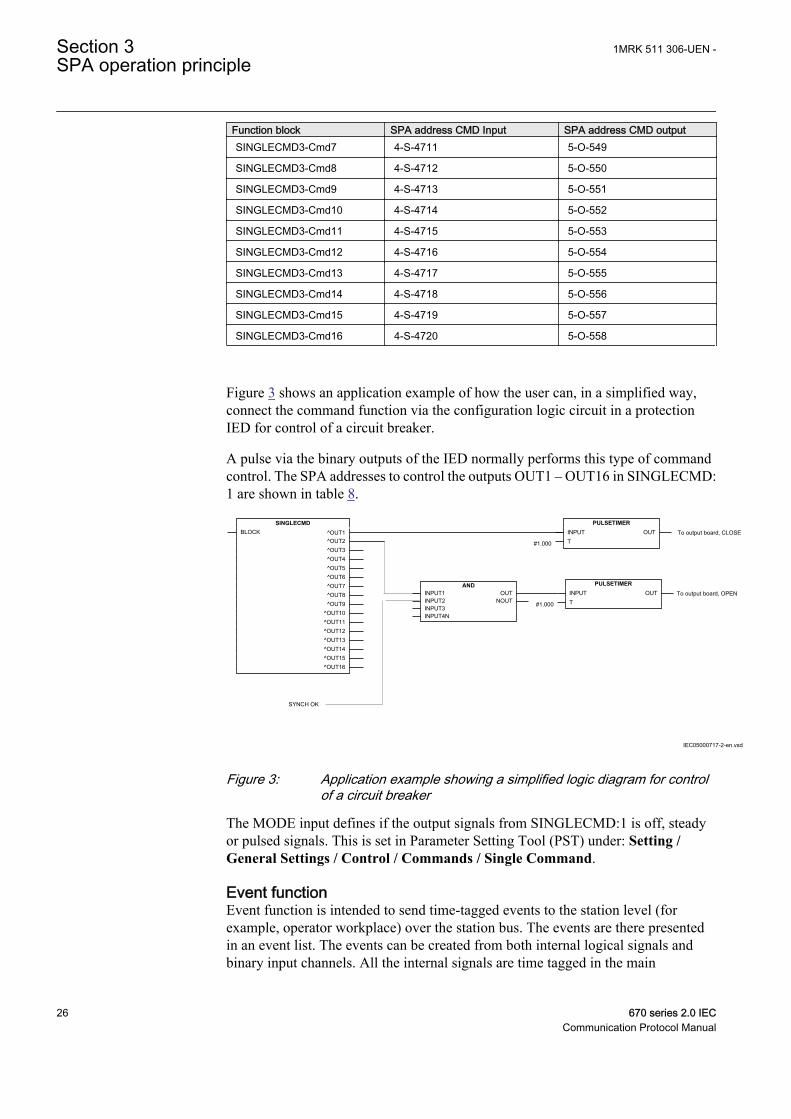
Function block SPA address CMD Input SPA address CMD outputSINGLECMD3-Cmd7 4-S-4711 5-O-549
SINGLECMD3-Cmd8 4-S-4712 5-O-550
SINGLECMD3-Cmd9 4-S-4713 5-O-551
SINGLECMD3-Cmd10 4-S-4714 5-O-552
SINGLECMD3-Cmd11 4-S-4715 5-O-553
SINGLECMD3-Cmd12 4-S-4716 5-O-554
SINGLECMD3-Cmd13 4-S-4717 5-O-555
SINGLECMD3-Cmd14 4-S-4718 5-O-556
SINGLECMD3-Cmd15 4-S-4719 5-O-557
SINGLECMD3-Cmd16 4-S-4720 5-O-558
Figure 3 shows an application example of how the user can, in a simplified way,connect the command function via the configuration logic circuit in a protectionIED for control of a circuit breaker.
A pulse via the binary outputs of the IED normally performs this type of commandcontrol. The SPA addresses to control the outputs OUT1 – OUT16 in SINGLECMD:1 are shown in table 8.
To output board, CLOSESINGLECMD
BLOCK ^OUT1^OUT2^OUT3^OUT4^OUT5^OUT6^OUT7^OUT8^OUT9
^OUT10^OUT11^OUT12^OUT13^OUT14^OUT15^OUT16
ANDINPUT1INPUT2INPUT3INPUT4N
OUTNOUT
PULSETIMERINPUTT
OUT
SYNCH OK
PULSETIMERINPUTT
OUT
#1.000
#1.000
To output board, OPEN
IEC05000717-2-en.vsd
IEC05000717 V2 EN
Figure 3: Application example showing a simplified logic diagram for controlof a circuit breaker
The MODE input defines if the output signals from SINGLECMD:1 is off, steadyor pulsed signals. This is set in Parameter Setting Tool (PST) under: Setting /General Settings / Control / Commands / Single Command.
Event functionEvent function is intended to send time-tagged events to the station level (forexample, operator workplace) over the station bus. The events are there presentedin an event list. The events can be created from both internal logical signals andbinary input channels. All the internal signals are time tagged in the main
Section 3 1MRK 511 306-UEN -SPA operation principle
26 670 series 2.0 IECCommunication Protocol Manual
processing module, while the binary input channels are time tagged directly oneach I/O module. The events are produced according to the set event masks. Theevent masks are treated commonly for both the LON and SPA channels. All eventsaccording to the event mask are stored in a buffer, which contains up to 1000events. If new events appear before the oldest event in the buffer is read, the oldestevent is overwritten and an overflow alarm appears.
Two special signals for event registration purposes are available in the IED,Terminal Restarted (0E50) and Event buffer overflow (0E51).
The input parameters can be set individually from the Parameter Setting Tool(PST) under: Setting / General Setting / Monitoring / Event Function as follows:
• No events• OnSet, at pick-up of the signal• OnReset, at drop-out of the signal• OnChange, at both pick-up and drop-out of the signal• AutoDetect, event system itself make the reporting decision, (reporting criteria
for integers has no semantic, prefer to be set by the user)
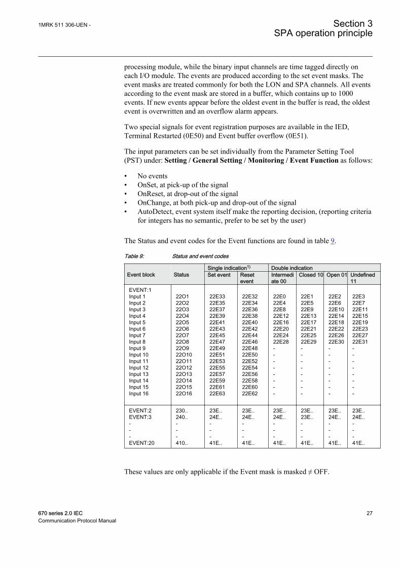
The Status and event codes for the Event functions are found in table 9.
Table 9: Status and event codes
Single indication1) Double indication Event block Status Set event Reset
eventIntermediate 00
Closed 10 Open 01 Undefined11
EVENT:1Input 1Input 2Input 3Input 4Input 5Input 6Input 7Input 8Input 9Input 10Input 11Input 12Input 13Input 14Input 15Input 16
22O122O222O322O422O522O622O722O822O922O1022O1122O1222O1322O1422O1522O16
22E3322E3522E3722E3922E4122E4322E4522E4722E4922E5122E5322E5522E5722E5922E6122E63
22E3222E3422E3622E3822E4022E4222E4422E4622E4822E5022E5222E5422E5622E5822E6022E62
22E022E422E822E1222E1622E2022E2422E28--------
22E122E522E922E1322E1722E2122E2522E29--------
22E222E622E1022E1422E1822E2222E2622E30--------
22E322E722E1122E1522E1922E2322E2722E31--------
EVENT:2EVENT:3---EVENT:20
230..240..---410..
23E..24E..---41E..
23E..24E..---41E..
23E..24E..---41E..
23E..23E..---41E..
23E..24E..---41E..
23E..24E..---41E..
These values are only applicable if the Event mask is masked ≠ OFF.
1MRK 511 306-UEN - Section 3SPA operation principle
670 series 2.0 IEC 27Communication Protocol Manual
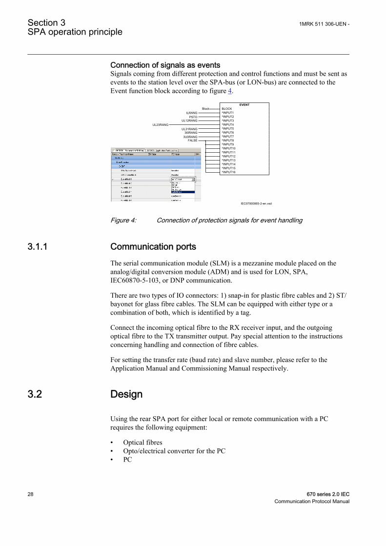
Connection of signals as eventsSignals coming from different protection and control functions and must be sent asevents to the station level over the SPA-bus (or LON-bus) are connected to theEvent function block according to figure 4.
EVENTBLOCK^INPUT1^INPUT2^INPUT3^INPUT4^INPUT5^INPUT6^INPUT7^INPUT8^INPUT9^INPUT10^INPUT11^INPUT12^INPUT13^INPUT14^INPUT15^INPUT16
BlockILRANG
PSTOUL12RANG
UL31RANGUL23RANG
3I0RANG3U0RANG
FALSE
IEC07000065-2-en.vsd
IEC07000065 V2 EN
Figure 4: Connection of protection signals for event handling
3.1.1 Communication portsThe serial communication module (SLM) is a mezzanine module placed on theanalog/digital conversion module (ADM) and is used for LON, SPA,IEC60870-5-103, or DNP communication.
There are two types of IO connectors: 1) snap-in for plastic fibre cables and 2) ST/bayonet for glass fibre cables. The SLM can be equipped with either type or acombination of both, which is identified by a tag.
Connect the incoming optical fibre to the RX receiver input, and the outgoingoptical fibre to the TX transmitter output. Pay special attention to the instructionsconcerning handling and connection of fibre cables.
For setting the transfer rate (baud rate) and slave number, please refer to theApplication Manual and Commissioning Manual respectively.
3.2 Design
Using the rear SPA port for either local or remote communication with a PCrequires the following equipment:
• Optical fibres• Opto/electrical converter for the PC• PC
Section 3 1MRK 511 306-UEN -SPA operation principle
28 670 series 2.0 IECCommunication Protocol Manual

The software needed in the PC, either local or remote, is PCM600. (Note! SPAcannot be used with PCM600 2.6).
When communicating between the local HMI and a PC, the only hardware requiredis a front-connection cable. Note! SPA cannot be used from LHMI front, except forusing "FSTACCS", that is, Field Service Tool Access.
1MRK 511 306-UEN - Section 3SPA operation principle
670 series 2.0 IEC 29Communication Protocol Manual

30
Section 4 SPA settings
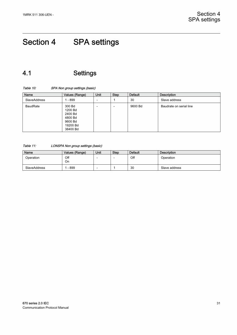
4.1 Settings
Table 10: SPA Non group settings (basic)
Name Values (Range) Unit Step Default DescriptionSlaveAddress 1 - 899 - 1 30 Slave address
BaudRate 300 Bd1200 Bd2400 Bd4800 Bd9600 Bd19200 Bd38400 Bd
- - 9600 Bd Baudrate on serial line
Table 11: LONSPA Non group settings (basic)
Name Values (Range) Unit Step Default DescriptionOperation Off
On- - Off Operation
SlaveAddress 1 - 899 - 1 30 Slave address
1MRK 511 306-UEN - Section 4SPA settings
670 series 2.0 IEC 31Communication Protocol Manual

32
Section 5 SPA technical data
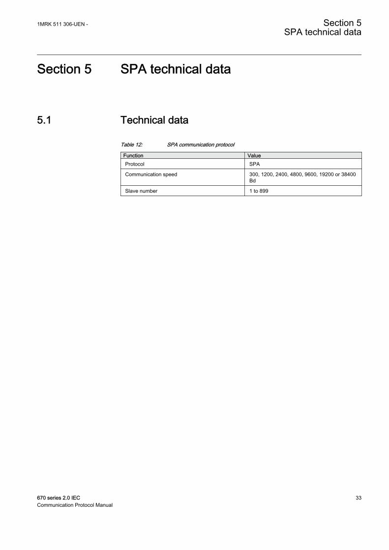
5.1 Technical data
Table 12: SPA communication protocol
Function ValueProtocol SPA
Communication speed 300, 1200, 2400, 4800, 9600, 19200 or 38400Bd
Slave number 1 to 899
1MRK 511 306-UEN - Section 5SPA technical data
670 series 2.0 IEC 33Communication Protocol Manual

34
Section 6 Establishing connection and verifying theSPA/IEC- communication
6.1 Establishing connection and verifying the SPA/IEC-communication
About this chapterThis chapter contains instructions on how to establish connection and verify thatthe SPA/IEC-communication operates as intended, when the IED is connected to amonitoring or control system via the rear SPA/IEC port.
6.1.1 Entering settingsIf the IED is connected to a monitoring or control system via the rear SPA/IECport, the SPA/IEC port has to be set either for SPA or IEC use.
6.1.1.1 Entering SPA settings
The SPA/IEC port is located on the rear side of the IED. Two types of interfacescan be used:
• for plastic fibres with connector type HFBR• for glass fibres with connectors type ST
When using the SPA protocol, the rear SPA/IEC port must be set for SPA use.
Procedure
1. Set the operation of the rear optical SPA/IEC port to “SPA”.The operation of the rear SPA port can be found on the local HMI underMain menu/Configuration/Communication/Station communication/Portconfiguration/SLM optical serial port/PROTOCOL:1When the setting is entered the IED restarts automatically. After the restartthe SPA/IEC port operates as a SPA port.
2. Set the slave number and baud rate for the rear SPA portThe slave number and baud rate can be found on the local HMI under Mainmenu/Configuration/Communication/Station communication/SPA/SPA:1Set the same slave number and baud rate as set in the SMS system for the IED.
1MRK 511 306-UEN - Section 6Establishing connection and verifying the SPA/IEC- communication
670 series 2.0 IEC 35Communication Protocol Manual
6.1.2 Verifying the communicationTo verify that the rear communication with the SMS/SCS system is working, thereare some different methods. Choose one of the following.
6.1.2.1 Verifying SPA communication
Procedure
1. Use a SPA-emulator and send “RF” to the IED. The answer from the IEDshould be the type and version of it, for example, “REL670 2.0...”.
2. Generate one binary event by activating a function, which is configured to anevent block where the used input is set to generate events on SPA. Theconfiguration must be made with the PCM600 software. Verify that the eventis presented in the SMS/SCS system.
During the following tests of the different functions in the IED, verify that theevents and indications in the SMS/SCS system are as expected.
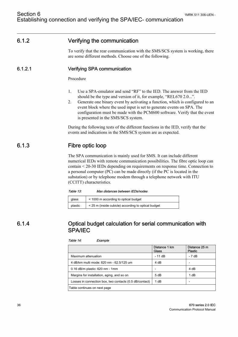
6.1.3 Fibre optic loopThe SPA communication is mainly used for SMS. It can include differentnumerical IEDs with remote communication possibilities. The fibre optic loop cancontain < 20-30 IEDs depending on requirements on response time. Connection toa personal computer (PC) can be made directly (if the PC is located in thesubstation) or by telephone modem through a telephone network with ITU(CCITT) characteristics.
Table 13: Max distances between IEDs/nodes
glass < 1000 m according to optical budget
plastic < 25 m (inside cubicle) according to optical budget
6.1.4 Optical budget calculation for serial communication withSPA/IECTable 14: Example
Distance 1 kmGlass
Distance 25 mPlastic
Maximum attenuation - 11 dB - 7 dB
4 dB/km multi mode: 820 nm - 62.5/125 um 4 dB -
0.16 dB/m plastic: 620 nm - 1mm - 4 dB
Margins for installation, aging, and so on 5 dB 1 dB
Losses in connection box, two contacts (0.5 dB/contact) 1 dB -
Table continues on next page
Section 6 1MRK 511 306-UEN -Establishing connection and verifying the SPA/IEC- communication
36 670 series 2.0 IECCommunication Protocol Manual

Distance 1 kmGlass
Distance 25 mPlastic
Losses in connection box, two contacts (1 dB/contact) - 2 dB
Margin for 2 repair splices (0.5 dB/splice) 1 dB -
Maximum total attenuation 11 dB 7 dB
1MRK 511 306-UEN - Section 6Establishing connection and verifying the SPA/IEC- communication
670 series 2.0 IEC 37Communication Protocol Manual

38
Section 7 SPA functions
7.1 Event function EVENT
7.1.1 IdentificationFunction description IEC 61850
identificationIEC 60617identification
ANSI/IEEE C37.2device number
Event function EVENTS00946 V1 EN
-
When using a Substation Automation system with LON or SPA communication,time-tagged events can be sent at change or cyclically from the IED to the stationlevel. These events are created from any available signal in the IED that isconnected to the Event function (EVENT). The event function block is used forLON and SPA communication.
Analog and double indication values are also transferred through EVENT function.
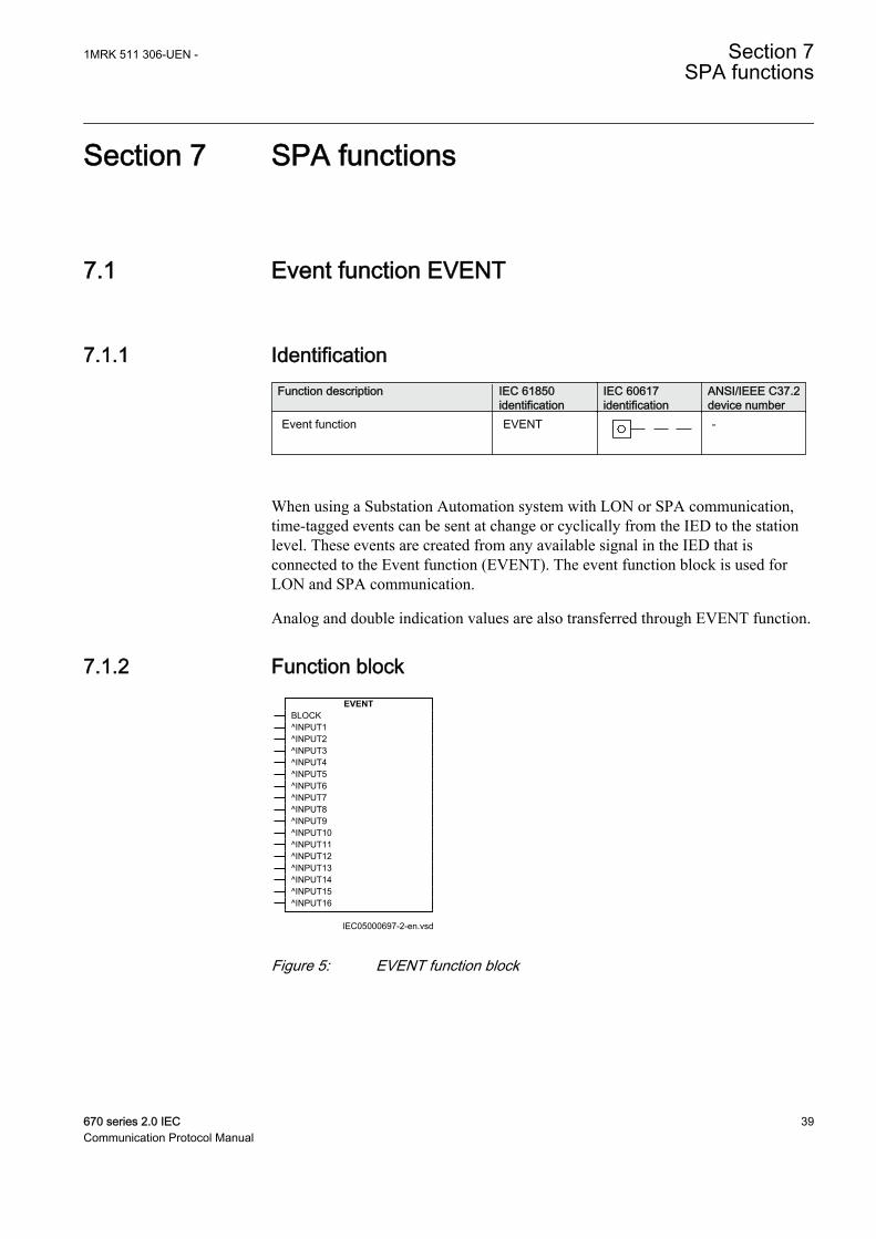
7.1.2 Function block
IEC05000697-2-en.vsd
EVENTBLOCK^INPUT1^INPUT2^INPUT3^INPUT4^INPUT5^INPUT6^INPUT7^INPUT8^INPUT9^INPUT10^INPUT11^INPUT12^INPUT13^INPUT14^INPUT15^INPUT16
IEC05000697 V2 EN
Figure 5: EVENT function block
1MRK 511 306-UEN - Section 7SPA functions
670 series 2.0 IEC 39Communication Protocol Manual
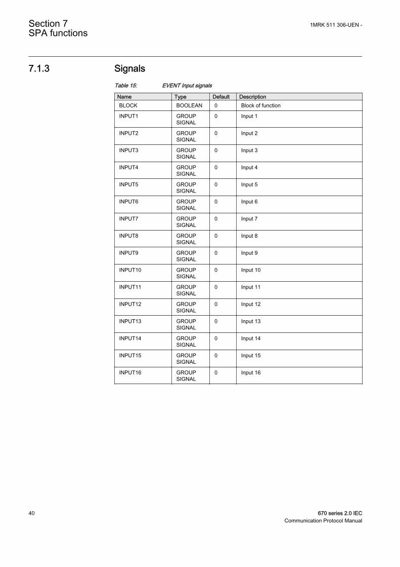
7.1.3 SignalsTable 15: EVENT Input signals
Name Type Default DescriptionBLOCK BOOLEAN 0 Block of function
INPUT1 GROUPSIGNAL
0 Input 1
INPUT2 GROUPSIGNAL
0 Input 2
INPUT3 GROUPSIGNAL
0 Input 3
INPUT4 GROUPSIGNAL
0 Input 4
INPUT5 GROUPSIGNAL
0 Input 5
INPUT6 GROUPSIGNAL
0 Input 6
INPUT7 GROUPSIGNAL
0 Input 7
INPUT8 GROUPSIGNAL
0 Input 8
INPUT9 GROUPSIGNAL
0 Input 9
INPUT10 GROUPSIGNAL
0 Input 10
INPUT11 GROUPSIGNAL
0 Input 11
INPUT12 GROUPSIGNAL
0 Input 12
INPUT13 GROUPSIGNAL
0 Input 13
INPUT14 GROUPSIGNAL
0 Input 14
INPUT15 GROUPSIGNAL
0 Input 15
INPUT16 GROUPSIGNAL
0 Input 16
Section 7 1MRK 511 306-UEN -SPA functions
40 670 series 2.0 IECCommunication Protocol Manual
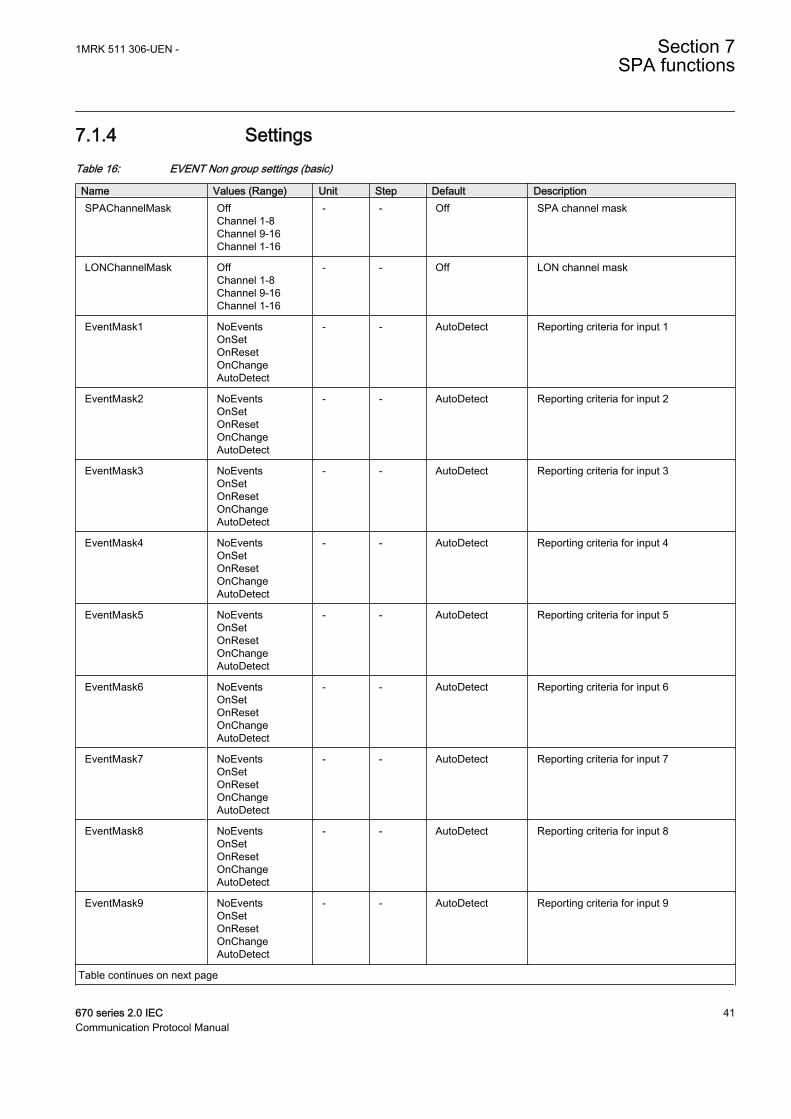
7.1.4 SettingsTable 16: EVENT Non group settings (basic)
Name Values (Range) Unit Step Default DescriptionSPAChannelMask Off
Channel 1-8Channel 9-16Channel 1-16
- - Off SPA channel mask
LONChannelMask OffChannel 1-8Channel 9-16Channel 1-16
- - Off LON channel mask
EventMask1 NoEventsOnSetOnResetOnChangeAutoDetect
- - AutoDetect Reporting criteria for input 1
EventMask2 NoEventsOnSetOnResetOnChangeAutoDetect
- - AutoDetect Reporting criteria for input 2
EventMask3 NoEventsOnSetOnResetOnChangeAutoDetect
- - AutoDetect Reporting criteria for input 3
EventMask4 NoEventsOnSetOnResetOnChangeAutoDetect
- - AutoDetect Reporting criteria for input 4
EventMask5 NoEventsOnSetOnResetOnChangeAutoDetect
- - AutoDetect Reporting criteria for input 5
EventMask6 NoEventsOnSetOnResetOnChangeAutoDetect
- - AutoDetect Reporting criteria for input 6
EventMask7 NoEventsOnSetOnResetOnChangeAutoDetect
- - AutoDetect Reporting criteria for input 7
EventMask8 NoEventsOnSetOnResetOnChangeAutoDetect
- - AutoDetect Reporting criteria for input 8
EventMask9 NoEventsOnSetOnResetOnChangeAutoDetect
- - AutoDetect Reporting criteria for input 9
Table continues on next page
1MRK 511 306-UEN - Section 7SPA functions
670 series 2.0 IEC 41Communication Protocol Manual
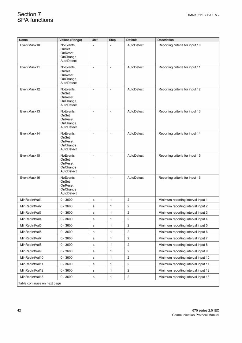
Name Values (Range) Unit Step Default DescriptionEventMask10 NoEvents
OnSetOnResetOnChangeAutoDetect
- - AutoDetect Reporting criteria for input 10
EventMask11 NoEventsOnSetOnResetOnChangeAutoDetect
- - AutoDetect Reporting criteria for input 11
EventMask12 NoEventsOnSetOnResetOnChangeAutoDetect
- - AutoDetect Reporting criteria for input 12
EventMask13 NoEventsOnSetOnResetOnChangeAutoDetect
- - AutoDetect Reporting criteria for input 13
EventMask14 NoEventsOnSetOnResetOnChangeAutoDetect
- - AutoDetect Reporting criteria for input 14
EventMask15 NoEventsOnSetOnResetOnChangeAutoDetect
- - AutoDetect Reporting criteria for input 15
EventMask16 NoEventsOnSetOnResetOnChangeAutoDetect
- - AutoDetect Reporting criteria for input 16
MinRepIntVal1 0 - 3600 s 1 2 Minimum reporting interval input 1
MinRepIntVal2 0 - 3600 s 1 2 Minimum reporting interval input 2
MinRepIntVal3 0 - 3600 s 1 2 Minimum reporting interval input 3
MinRepIntVal4 0 - 3600 s 1 2 Minimum reporting interval input 4
MinRepIntVal5 0 - 3600 s 1 2 Minimum reporting interval input 5
MinRepIntVal6 0 - 3600 s 1 2 Minimum reporting interval input 6
MinRepIntVal7 0 - 3600 s 1 2 Minimum reporting interval input 7
MinRepIntVal8 0 - 3600 s 1 2 Minimum reporting interval input 8
MinRepIntVal9 0 - 3600 s 1 2 Minimum reporting interval input 9
MinRepIntVal10 0 - 3600 s 1 2 Minimum reporting interval input 10
MinRepIntVal11 0 - 3600 s 1 2 Minimum reporting interval input 11
MinRepIntVal12 0 - 3600 s 1 2 Minimum reporting interval input 12
MinRepIntVal13 0 - 3600 s 1 2 Minimum reporting interval input 13
Table continues on next page
Section 7 1MRK 511 306-UEN -SPA functions
42 670 series 2.0 IECCommunication Protocol Manual
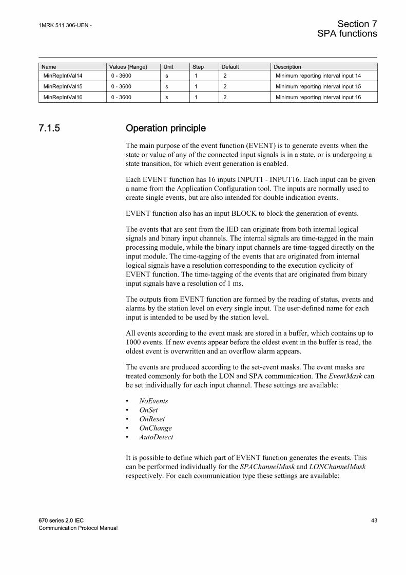
Name Values (Range) Unit Step Default DescriptionMinRepIntVal14 0 - 3600 s 1 2 Minimum reporting interval input 14
MinRepIntVal15 0 - 3600 s 1 2 Minimum reporting interval input 15
MinRepIntVal16 0 - 3600 s 1 2 Minimum reporting interval input 16
7.1.5 Operation principleThe main purpose of the event function (EVENT) is to generate events when thestate or value of any of the connected input signals is in a state, or is undergoing astate transition, for which event generation is enabled.
Each EVENT function has 16 inputs INPUT1 - INPUT16. Each input can be givena name from the Application Configuration tool. The inputs are normally used tocreate single events, but are also intended for double indication events.
EVENT function also has an input BLOCK to block the generation of events.
The events that are sent from the IED can originate from both internal logicalsignals and binary input channels. The internal signals are time-tagged in the mainprocessing module, while the binary input channels are time-tagged directly on theinput module. The time-tagging of the events that are originated from internallogical signals have a resolution corresponding to the execution cyclicity ofEVENT function. The time-tagging of the events that are originated from binaryinput signals have a resolution of 1 ms.
The outputs from EVENT function are formed by the reading of status, events andalarms by the station level on every single input. The user-defined name for eachinput is intended to be used by the station level.
All events according to the event mask are stored in a buffer, which contains up to1000 events. If new events appear before the oldest event in the buffer is read, theoldest event is overwritten and an overflow alarm appears.
The events are produced according to the set-event masks. The event masks aretreated commonly for both the LON and SPA communication. The EventMask canbe set individually for each input channel. These settings are available:
• NoEvents• OnSet• OnReset• OnChange• AutoDetect
It is possible to define which part of EVENT function generates the events. Thiscan be performed individually for the SPAChannelMask and LONChannelMaskrespectively. For each communication type these settings are available:
1MRK 511 306-UEN - Section 7SPA functions
670 series 2.0 IEC 43Communication Protocol Manual
• Off• Channel 1-8• Channel 9-16• Channel 1-16
For LON communication the events normally are sent to station level at change. Itis possibly also to set a time for cyclic sending of the events individually for eachinput channel.
To protect the SA system from signals with a high change rate that can easilysaturate the event system or the communication subsystems behind it, a quotalimiter is implemented. If an input creates events at a rate that completely consumethe granted quota then further events from the channel will be blocked. This blockwill be removed when the input calms down and the accumulated quota reach 66%of the maximum burst quota. The maximum burst quota per input channel is 45events per second.
7.2 Setting guidelines
The parameters for the Event (EVENT) function are set via the local HMI or PCM600.
7.2.1.1 EventMask (Ch_1 - 16)
The inputs can be set individually as:
• NoEvents• OnSet, at pick-up of the signal• OnReset, at drop-out of the signal• OnChange, at both pick-up and drop-out of the signal• AutoDetect
7.2.1.2 LONChannelMask or SPAChannelMask
Definition of which part of the event function block that shall generate events:
• Off• Channel 1-8• Channel 9-16• Channel 1-16
7.2.1.3 MinRepIntVal (1 - 16)
A time interval between cyclic events can be set individually for each inputchannel. This can be set between 0.0 s to 1000.0 s in steps of 0.1 s. It shouldnormally be set to 0, that is, no cyclic communication.
Section 7 1MRK 511 306-UEN -SPA functions
44 670 series 2.0 IECCommunication Protocol Manual
It is important to set the time interval for cyclic events in anoptimized way to minimize the load on the station bus.
7.3 Logical signal status report BINSTATREP
7.3.1 IdentificationFunction description IEC 61850
identificationIEC 60617identification
ANSI/IEEE C37.2device number
Logical signal status report BINSTATREP - -
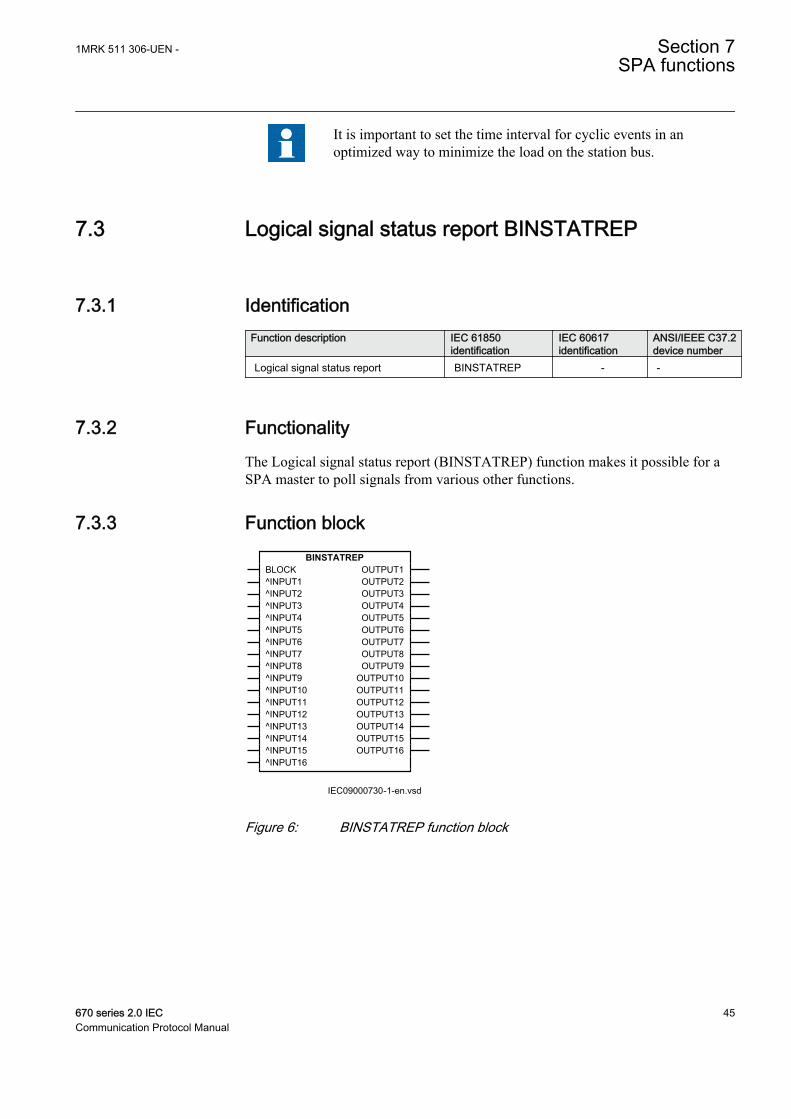
7.3.2 FunctionalityThe Logical signal status report (BINSTATREP) function makes it possible for aSPA master to poll signals from various other functions.
7.3.3 Function blockBINSTATREP
BLOCK^INPUT1^INPUT2^INPUT3^INPUT4^INPUT5^INPUT6^INPUT7^INPUT8^INPUT9^INPUT10^INPUT11^INPUT12^INPUT13^INPUT14^INPUT15^INPUT16
OUTPUT1OUTPUT2OUTPUT3OUTPUT4OUTPUT5OUTPUT6OUTPUT7OUTPUT8OUTPUT9
OUTPUT10OUTPUT11OUTPUT12OUTPUT13OUTPUT14OUTPUT15OUTPUT16
IEC09000730-1-en.vsdIEC09000730 V1 EN
Figure 6: BINSTATREP function block
1MRK 511 306-UEN - Section 7SPA functions
670 series 2.0 IEC 45Communication Protocol Manual
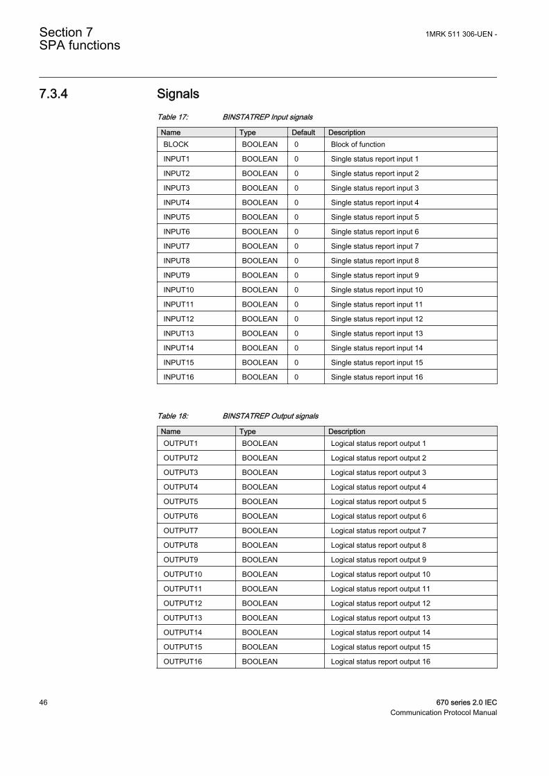
7.3.4 SignalsTable 17: BINSTATREP Input signals
Name Type Default DescriptionBLOCK BOOLEAN 0 Block of function
INPUT1 BOOLEAN 0 Single status report input 1
INPUT2 BOOLEAN 0 Single status report input 2
INPUT3 BOOLEAN 0 Single status report input 3
INPUT4 BOOLEAN 0 Single status report input 4
INPUT5 BOOLEAN 0 Single status report input 5
INPUT6 BOOLEAN 0 Single status report input 6
INPUT7 BOOLEAN 0 Single status report input 7
INPUT8 BOOLEAN 0 Single status report input 8
INPUT9 BOOLEAN 0 Single status report input 9
INPUT10 BOOLEAN 0 Single status report input 10
INPUT11 BOOLEAN 0 Single status report input 11
INPUT12 BOOLEAN 0 Single status report input 12
INPUT13 BOOLEAN 0 Single status report input 13
INPUT14 BOOLEAN 0 Single status report input 14
INPUT15 BOOLEAN 0 Single status report input 15
INPUT16 BOOLEAN 0 Single status report input 16
Table 18: BINSTATREP Output signals
Name Type DescriptionOUTPUT1 BOOLEAN Logical status report output 1
OUTPUT2 BOOLEAN Logical status report output 2
OUTPUT3 BOOLEAN Logical status report output 3
OUTPUT4 BOOLEAN Logical status report output 4
OUTPUT5 BOOLEAN Logical status report output 5
OUTPUT6 BOOLEAN Logical status report output 6
OUTPUT7 BOOLEAN Logical status report output 7
OUTPUT8 BOOLEAN Logical status report output 8
OUTPUT9 BOOLEAN Logical status report output 9
OUTPUT10 BOOLEAN Logical status report output 10
OUTPUT11 BOOLEAN Logical status report output 11
OUTPUT12 BOOLEAN Logical status report output 12
OUTPUT13 BOOLEAN Logical status report output 13
OUTPUT14 BOOLEAN Logical status report output 14
OUTPUT15 BOOLEAN Logical status report output 15
OUTPUT16 BOOLEAN Logical status report output 16
Section 7 1MRK 511 306-UEN -SPA functions
46 670 series 2.0 IECCommunication Protocol Manual
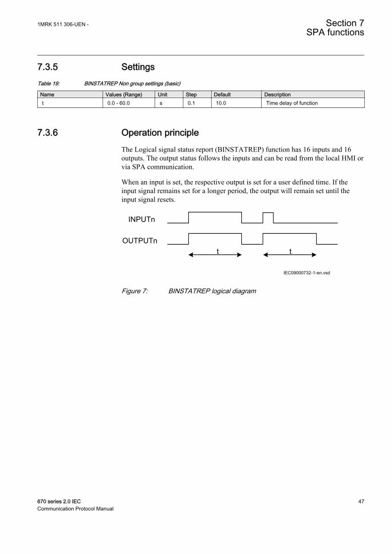
7.3.5 SettingsTable 19: BINSTATREP Non group settings (basic)
Name Values (Range) Unit Step Default Descriptiont 0.0 - 60.0 s 0.1 10.0 Time delay of function
7.3.6 Operation principleThe Logical signal status report (BINSTATREP) function has 16 inputs and 16outputs. The output status follows the inputs and can be read from the local HMI orvia SPA communication.
When an input is set, the respective output is set for a user defined time. If theinput signal remains set for a longer period, the output will remain set until theinput signal resets.
t t
INPUTn
OUTPUTn
IEC09000732-1-en.vsdIEC09000732 V1 EN
Figure 7: BINSTATREP logical diagram
1MRK 511 306-UEN - Section 7SPA functions
670 series 2.0 IEC 47Communication Protocol Manual

48
Section 8 Glossary
8.1 Glossary
AC Alternating current
ACC Actual channel
ACT Application configuration tool within PCM600
A/D converter Analog-to-digital converter
ADBS Amplitude deadband supervision
ADM Analog digital conversion module, with timesynchronization
AI Analog input
ANSI American National Standards Institute
AR Autoreclosing
ASCT Auxiliary summation current transformer
ASD Adaptive signal detection
ASDU Application service data unit
AWG American Wire Gauge standard
BBP Busbar protection
BFOC/2,5 Bayonet fibre optic connector
BFP Breaker failure protection
BI Binary input
BIM Binary input module
BOM Binary output module
BOS Binary outputs status
BR External bistable relay
BS British Standards
BSR Binary signal transfer function, receiver blocks
BST Binary signal transfer function, transmit blocks
C37.94 IEEE/ANSI protocol used when sending binary signalsbetween IEDs
CAN Controller Area Network. ISO standard (ISO 11898) forserial communication
1MRK 511 306-UEN - Section 8Glossary
670 series 2.0 IEC 49Communication Protocol Manual

CB Circuit breaker
CBM Combined backplane module
CCITT Consultative Committee for International Telegraph andTelephony. A United Nations-sponsored standards bodywithin the International Telecommunications Union.
CCM CAN carrier module
CCVT Capacitive Coupled Voltage Transformer
Class C Protection Current Transformer class as per IEEE/ ANSI
CMPPS Combined megapulses per second
CMT Communication Management tool in PCM600
CO cycle Close-open cycle
Codirectional Way of transmitting G.703 over a balanced line. Involvestwo twisted pairs making it possible to transmitinformation in both directions
COM Command
COMTRADE Standard Common Format for Transient Data Exchangeformat for Disturbance recorder according to IEEE/ANSIC37.111, 1999 / IEC60255-24
Contra-directional Way of transmitting G.703 over a balanced line. Involvesfour twisted pairs, two of which are used for transmittingdata in both directions and two for transmitting clock signals
COT Cause of transmission
CPU Central processing unit
CR Carrier receive
CRC Cyclic redundancy check
CROB Control relay output block
CS Carrier send
CT Current transformer
CU Communication unit
CVT or CCVT Capacitive voltage transformer
DAR Delayed autoreclosing
DARPA Defense Advanced Research Projects Agency (The USdeveloper of the TCP/IP protocol etc.)
DBDL Dead bus dead line
DBLL Dead bus live line
DC Direct current
DFC Data flow control
Section 8 1MRK 511 306-UEN -Glossary
50 670 series 2.0 IECCommunication Protocol Manual
DFT Discrete Fourier transform
DHCP Dynamic Host Configuration Protocol
DIP-switch Small switch mounted on a printed circuit board
DI Digital input
DLLB Dead line live bus
DNP Distributed Network Protocol as per IEEE Std 1815-2012
DR Disturbance recorder
DRAM Dynamic random access memory
DRH Disturbance report handler
DSP Digital signal processor
DTT Direct transfer trip scheme
EHV network Extra high voltage network
EIA Electronic Industries Association
EMC Electromagnetic compatibility
EMF Electromotive force
EMI Electromagnetic interference
EnFP End fault protection
EPA Enhanced performance architecture
ESD Electrostatic discharge
F-SMA Type of optical fibre connector
FAN Fault number
FCB Flow control bit; Frame count bit
FOX 20 Modular 20 channel telecommunication system for speech,data and protection signals
FOX 512/515 Access multiplexer
FOX 6Plus Compact time-division multiplexer for the transmission ofup to seven duplex channels of digital data over optical fibers
FUN Function type
G.703 Electrical and functional description for digital lines usedby local telephone companies. Can be transported overbalanced and unbalanced lines
GCM Communication interface module with carrier of GPSreceiver module
GDE Graphical display editor within PCM600
GI General interrogation command
GIS Gas-insulated switchgear
1MRK 511 306-UEN - Section 8Glossary
670 series 2.0 IEC 51Communication Protocol Manual
GOOSE Generic object-oriented substation event
GPS Global positioning system
GSAL Generic security application
GTM GPS Time Module
HDLC protocol High-level data link control, protocol based on the HDLCstandard
HFBR connectortype
Plastic fiber connector
HMI Human-machine interface
HSAR High speed autoreclosing
HV High-voltage
HVDC High-voltage direct current
IDBS Integrating deadband supervision
IEC International Electrical Committee
IEC 60044-6 IEC Standard, Instrument transformers – Part 6:Requirements for protective current transformers fortransient performance
IEC 60870-5-103 Communication standard for protection equipment. Aserial master/slave protocol for point-to-pointcommunication
IEC 61850 Substation automation communication standard
IEC 61850–8–1 Communication protocol standard
IEEE Institute of Electrical and Electronics Engineers
IEEE 802.12 A network technology standard that provides 100 Mbits/son twisted-pair or optical fiber cable
IEEE P1386.1 PCI Mezzanine Card (PMC) standard for local busmodules. References the CMC (IEEE P1386, also knownas Common Mezzanine Card) standard for the mechanicsand the PCI specifications from the PCI SIG (SpecialInterest Group) for the electrical EMF (Electromotive force).
IEEE 1686 Standard for Substation Intelligent Electronic Devices(IEDs) Cyber Security Capabilities
IED Intelligent electronic device
I-GIS Intelligent gas-insulated switchgear
IOM Binary input/output module
Instance When several occurrences of the same function areavailable in the IED, they are referred to as instances ofthat function. One instance of a function is identical toanother of the same kind but has a different number in the
Section 8 1MRK 511 306-UEN -Glossary
52 670 series 2.0 IECCommunication Protocol Manual
IED user interfaces. The word "instance" is sometimesdefined as an item of information that is representative of atype. In the same way an instance of a function in the IEDis representative of a type of function.
IP 1. Internet protocol. The network layer for the TCP/IPprotocol suite widely used on Ethernet networks. IP is aconnectionless, best-effort packet-switching protocol. Itprovides packet routing, fragmentation and reassemblythrough the data link layer.2. Ingression protection, according to IEC 60529
IP 20 Ingression protection, according to IEC 60529, level 20
IP 40 Ingression protection, according to IEC 60529, level 40
IP 54 Ingression protection, according to IEC 60529, level 54
IRF Internal failure signal
IRIG-B: InterRange Instrumentation Group Time code format B,standard 200
ITU International Telecommunications Union
LAN Local area network
LIB 520 High-voltage software module
LCD Liquid crystal display
LDCM Line differential communication module
LDD Local detection device
LED Light-emitting diode
LNT LON network tool
LON Local operating network
MCB Miniature circuit breaker
MCM Mezzanine carrier module
MIM Milli-ampere module
MPM Main processing module
MVAL Value of measurement
MVB Multifunction vehicle bus. Standardized serial busoriginally developed for use in trains.
NCC National Control Centre
NOF Number of grid faults
NUM Numerical module
OCO cycle Open-close-open cycle
OCP Overcurrent protection
1MRK 511 306-UEN - Section 8Glossary
670 series 2.0 IEC 53Communication Protocol Manual
OEM Optical Ethernet module
OLTC On-load tap changer
OTEV Disturbance data recording initiated by other event than start/pick-up
OV Overvoltage
Overreach A term used to describe how the relay behaves during afault condition. For example, a distance relay isoverreaching when the impedance presented to it is smallerthan the apparent impedance to the fault applied to thebalance point, that is, the set reach. The relay “sees” thefault but perhaps it should not have seen it.
PCI Peripheral component interconnect, a local data bus
PCM Pulse code modulation
PCM600 Protection and control IED manager
PC-MIP Mezzanine card standard
PMC PCI Mezzanine card
POR Permissive overreach
POTT Permissive overreach transfer trip
Process bus Bus or LAN used at the process level, that is, in nearproximity to the measured and/or controlled components
PSM Power supply module
PST Parameter setting tool within PCM600
PT ratio Potential transformer or voltage transformer ratio
PUTT Permissive underreach transfer trip
RASC Synchrocheck relay, COMBIFLEX
RCA Relay characteristic angle
RISC Reduced instruction set computer
RMS value Root mean square value
RS422 A balanced serial interface for the transmission of digitaldata in point-to-point connections
RS485 Serial link according to EIA standard RS485
RTC Real-time clock
RTU Remote terminal unit
SA Substation Automation
SBO Select-before-operate
SC Switch or push button to close
SCL Short circuit location
Section 8 1MRK 511 306-UEN -Glossary
54 670 series 2.0 IECCommunication Protocol Manual
SCS Station control system
SCADA Supervision, control and data acquisition
SCT System configuration tool according to standard IEC 61850
SDU Service data unit
SLM Serial communication module.
SMA connector Subminiature version A, A threaded connector withconstant impedance.
SMT Signal matrix tool within PCM600
SMS Station monitoring system
SNTP Simple network time protocol – is used to synchronizecomputer clocks on local area networks. This reduces therequirement to have accurate hardware clocks in everyembedded system in a network. Each embedded node caninstead synchronize with a remote clock, providing therequired accuracy.
SOF Status of fault
SPA Strömberg Protection Acquisition (SPA), a serial master/slave protocol for point-to-point communication
SRY Switch for CB ready condition
ST Switch or push button to trip
Starpoint Neutral point of transformer or generator
SVC Static VAr compensation
TC Trip coil
TCS Trip circuit supervision
TCP Transmission control protocol. The most commontransport layer protocol used on Ethernet and the Internet.
TCP/IP Transmission control protocol over Internet Protocol. Thede facto standard Ethernet protocols incorporated into4.2BSD Unix. TCP/IP was developed by DARPA forInternet working and encompasses both network layer andtransport layer protocols. While TCP and IP specify twoprotocols at specific protocol layers, TCP/IP is often usedto refer to the entire US Department of Defense protocolsuite based upon these, including Telnet, FTP, UDP andRDP.
TEF Time delayed earth-fault protection function
TM Transmit (disturbance data)
TNC connector Threaded Neill-Concelman, a threaded constant impedanceversion of a BNC connector
1MRK 511 306-UEN - Section 8Glossary
670 series 2.0 IEC 55Communication Protocol Manual
TP Trip (recorded fault)
TPZ, TPY, TPX,TPS
Current transformer class according to IEC
TRM Transformer Module. This module transforms currents andvoltages taken from the process into levels suitable forfurther signal processing.
TYP Type identification
UMT User management tool
Underreach A term used to describe how the relay behaves during afault condition. For example, a distance relay isunderreaching when the impedance presented to it isgreater than the apparent impedance to the fault applied tothe balance point, that is, the set reach. The relay does not“see” the fault but perhaps it should have seen it. See alsoOverreach.
UTC Coordinated Universal Time. A coordinated time scale,maintained by the Bureau International des Poids etMesures (BIPM), which forms the basis of a coordinateddissemination of standard frequencies and time signals.UTC is derived from International Atomic Time (TAI) bythe addition of a whole number of "leap seconds" tosynchronize it with Universal Time 1 (UT1), thus allowingfor the eccentricity of the Earth's orbit, the rotational axistilt (23.5 degrees), but still showing the Earth's irregularrotation, on which UT1 is based. The CoordinatedUniversal Time is expressed using a 24-hour clock, anduses the Gregorian calendar. It is used for aeroplane andship navigation, where it is also sometimes known by themilitary name, "Zulu time." "Zulu" in the phoneticalphabet stands for "Z", which stands for longitude zero.
UV Undervoltage
WEI Weak end infeed logic
VT Voltage transformer
X.21 A digital signalling interface primarily used for telecomequipment
3IO Three times zero-sequence current.Often referred to as theresidual or the earth-fault current
3UO Three times the zero sequence voltage. Often referred to asthe residual voltage or the neutral point voltage
Section 8 1MRK 511 306-UEN -Glossary
56 670 series 2.0 IECCommunication Protocol Manual

57

Contact us
ABB ABSubstation Automation ProductsSE-721 59 Västerås, SwedenPhone +46 (0) 21 32 50 00Fax +46 (0) 21 14 69 18
www.abb.com/substationautomation
1MR
K 5
11 3
06-U
EN
-©
Cop
yrig
ht 2
014
AB
B. A
ll rig
hts
rese
rved
.