space elevators a study in cable design and more space elevators a study in cable design and more...
TRANSCRIPT

1
Space Elevators
A Study in Cable Design and More
Nathaniel Hontz Mohar Kalra
[email protected] [email protected]
Rachel Lange Niyant Narang
[email protected] [email protected]
Danny Maguire [email protected]
New Jersey Governor’s School of Engineering and Technology 2016
Abstract
Conventional rocketry faces many
limitations. Infrequent launches, pollutants
dispersing in the atmosphere, and the high
cost of launches all make more developed
access to space difficult. A space elevator
can solve these problems with a unique
payload delivery system. Simply put, a
space elevator is a long cable that can stretch
from the surface of the Earth out into space.
Climbers can ascend this extraordinarily
strong cable for a variety of purposes. This
study has calculated the dimensions and
structure of the entire elevator. One of the
key objectives in this paper is to determine a
tether design constructed of newly-
developed carbon nanotubes and epoxy that
combines strength, efficiency and
adaptability in the relatively unfriendly
environments of space. Furthermore, this
study has examined and proposed solutions
to many of the common issues associated
with the space elevator concept. Lastly, this
paper encourages further investigation in the
development and mass production of carbon
nanotubes, as well as the economic
feasibility of space elevators in the near
future.
1. Introduction
1.1 Goals
This study aims to analyze the
feasibility of building a space elevator by
utilizing technology that is currently
available. As of today, the space elevator
proposal has remained entirely theoretical.
In fact, the basic design has advanced little
since its initial formal proposal in 2000 [1].
This is largely a result of the lack of
materials to construct a real space elevator.
The space elevator design hinges on the
ability of its tether to support itself over tens
of thousands of kilometers in Earth’s orbit,
but as of yet there exist few materials
capable of realistically fulfilling this
requirement. Theoretically, the tether can be
made of any material, but as the tether’s
altitude increases, it would have to widen
substantially to support its own weight. As
such, most studies on space elevators focus
on technologies that might exist decades in
the future. This study, however, will address
the matter of cable construction using
materials available to engineers today. In
order to accomplish this, various cable
2
configurations have been modeled in
SolidWorks, a computer aided design
software, to test their ability to handle stress.
In addition, this research seeks to provide
solutions to other issues associated with the
elevator, such as climber propulsion and
cable deployment.
1.2 Reasons for a Space Elevator
Everything that can be done with
rockets can be done cheaper and with larger
payloads using a space elevator [1].
Additionally, many missions that cannot be
accomplished with rocket launches will
become possible with the use of space
elevators. The environmental impacts of
launching rockets, including the fuel burned
and the engines falling back to Earth, will
disappear since space elevators can easily
transport cargo and humans without major
environmental concerns. Space-based solar
panels can provide cheap, clean power to
Earth’s surface. An increase in
communications and research will arise due
to the plethora of new satellites that can be
launched from the elevator. In addition,
space elevators will allow for relatively easy
disposal of dangerous nuclear or toxic waste
in the isolated vacuum of space. Moreover,
the space elevator can lead to a realistic
solution to space debris, a growing problem
which poses a serious danger of collision for
satellites and interference for future
excursions into space.
2. Background
2.1 Challenges with Elevator Design
The greatest challenge of building a
space elevator is the construction of the long
cable required to support the climbers. There
are few materials that offer even a
possibility for practical use. Furthermore, a
power system must be developed that will
enable long-distance transfer of energy to
the climbers. The deployment of the elevator
will be a delicate procedure as well. Other
complications include weather, atomic
oxygen corrosion, space debris, satellites,
radiation, and political regulation [1].
2.2 Assumptions
For the purposes of this study, it is
assumed that cable materials can be
replicated on a large scale with the same
length and strength as have been produced
in laboratories. This paper does not assume
the existence of any properties that have not
been experimentally observed. Furthermore,
a suitable epoxy for cable construction is
assumed to exist and able to be mass
produced.
2.3 Relevant Physics
The space elevator remains vertical
through a centrifugal “force” that appears to
act outwards on the cable. In reality, this
force is simply an observation resulting from
the inertia of a system. As an object swings
in a circular motion, its velocity is
perpendicular to its acceleration, which is
towards the body that it travels around. In
this type of motion, the “string” that
connects the object in motion to the center
of the circle it forms remains taut due to the
inertia resulting from the moving object’s
velocity. This is the concept behind the
space elevator. By anchoring a base point on
the equator of Earth, where the tangential
velocity on the surface will be the fastest,
the cable that connects the top of the space
elevator to the Earth will remain taut due to
its high tangential speed. However, to
overcome Earth's gravitational pull, the
centrifugal force must be greater than the
gravitational pull on the elevator. This
occurs at an altitude of 35,786 kilometers,
also known as geosynchronous orbit (GEO).

3
Therefore, the center of mass of the elevator
must be over 35,786 kilometers above the
surface of the earth. To minimize the
amount of cable required, a counterweight at
the end of the space elevator is necessary to
pull the center of mass up above GEO and
keep the elevator from collapsing back into
Earth. Nevertheless, the ribbon must be able
to support the tension from both below and
above [2]. Recent discoveries of new
nanomaterials allow for the strength
required.
During deployment, the angular
momentum of the spacecraft will be
conserved if no external torque is applied, as
the spacecraft rotates once per orbital
period. As the craft extends the cable, its
moment of inertia changes, slowing its
rotation and eventually causing a
catastrophic failure. This mechanism must
be taken into account.
Figure 1: Earth and space elevator
combination showing increasing cable
thickness [3]
3. Software
SolidWorks was utilized to create 3D
models of cable designs, as well as a scale
model of the Earth-space elevator system.
This program is a computer aided design
tool that allows users to create and simulate
3D objects. Moreover, tensile forces can be
measured using the simulation feature of
SolidWorks and stresses on various points in
the cable design were studied to determine
the best design for a space elevator. Despite
the fact that the properties of carbon
nanotubes are not programmed into the
software, a custom material was configured
in SolidWorks that emulated the properties
of carbon nanotubes. This custom material
was used to test various cable designs.
However, SolidWorks was not designed to
handle a structure of this magnitude and
designs could not be modeled to the desired
specifications. Whereas thousands of tubes
might be present in a cross-section of a real
cable, only a few dozen could be mapped in
the program. In addition, weaves, which
utilize semi-unstressed nanotubes, were
impossible to simulate accurately.
Unfortunately, this resulted in quantitative
inconsistencies between designs.
Nevertheless, invaluable qualitative
information was gained.
4. Cable Design
4.1 Material
The material used in a space elevator
is the most important aspect of the project.
For a long time, progress could not be made
in the field due to a lack of appropriate
materials. Even steel and Kevlar could not
be applied to the construction of a cable due
to the required taper ratio, the relationship
between the width of the cable at
geosynchronous orbit and the width of the
cable at the base point on Earth. For most
materials, the specific strength, or strength
to weight ratio, is too low; the increase in
width that will be needed as the cable
supports more and more of its own weight
will be too large. Ever since the conception
4
and development of the carbon nanotube,
the space elevator has been a realistic
possibility. Carbon nanotubes have the
greatest specific strength of any material
currently in existence and can enable a taper
ratio of 1.5 in theory [1]. For comparison,
steel will have a taper ratio of 1052
, which is
well over the width of the universe [4].
Furthermore, the material that makes up the
tether must be resistant to the variety of
environments that sections of the cable will
experience. The space elevator must be able
to withstand numerous abuses, including
severe weather within the atmosphere,
radiation in the Van Allen Belts, and debris
in space. Carbon nanotubes meet the
physical requirements necessary to endure
these conditions. In addition, an epoxy is
used to bind the relatively short segments of
nanotubes together at regular intervals. The
epoxy is durable and strong and forms a
composite with carbon nanotubes. Other
materials similar to carbon nanotubes, such
as boron nitride nanotubes and diamond
nanothreads, have also been made with
extremely high specific strengths [5].
However, their strength and ability to be
manufactured has not been researched
enough to be considered for the construction
of a space elevator in the present or near
future.
4.2 Microscopic Structure
Carbon nanotubes are a solid
allotrope of carbon constructed from sheets
of graphene. These sheets are configured in
a cylindrical structure with diameters of
approximately 10 angstroms [6]. In the
context of a space elevator, single-walled
nanotubes, or SWNTs, which can be viewed
as one roll of graphene, are preferred
because they have been studied more
extensively in terms of tensile strength than
multi-walled nanotubes (MWNTs) and will
therefore offer more reliable data on which
to base calculations. In addition to the
number of graphene layers, the pattern in
which the graphene is bonded together also
has a significant impact on the mechanical
and electrical properties of the nanotube.
The three types of configurations for
SWNTs are armchair, zigzag, and chiral,
which are based on the vector axis from
which a graphene sheet is rolled. In terms of
the feasibility of a space elevator today,
zigzag SWNTs are the best option because
they deform the least [7]. Deformation is
bad for the construction of a space elevator
because the tensile strength of the cable
cannot be predicted accurately after
deformation occurs and could cause
unknown consequences. Despite the fact that
zigzag SWNTs deform the least, they also
are the most brittle and break under the least
strength. This “least strength,” however, is
still strong enough for the cable of a space
elevator, even with a safety factor of 1.25.
Figure 2: Carbon nanotube microstructure
designs [6]
5
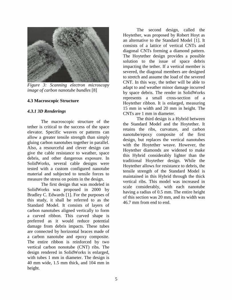
Figure 3: Scanning electron microscopy
image of carbon nanotube bundles [8]
4.3 Macroscopic Structure
4.3.1 3D Renderings
The macroscopic structure of the
tether is critical to the success of the space
elevator. Specific weaves or patterns can
allow a greater tensile strength than simply
gluing carbon nanotubes together in parallel.
Also, a resourceful and clever design can
give the cable resistance to weather, space
debris, and other dangerous exposure. In
SolidWorks, several cable designs were
tested with a custom configured nanotube
material and subjected to tensile forces to
measure the stress on points in the design.
The first design that was modeled in
SolidWorks was proposed in 2000 by
Bradley C. Edwards [1]. For the purposes of
this study, it shall be referred to as the
Standard Model. It consists of layers of
carbon nanotubes aligned vertically to form
a curved ribbon. This curved shape is
preferred as it would reduce potential
damage from debris impacts. These tubes
are connected by horizontal braces made of
a carbon nanotube and epoxy composite.
The entire ribbon is reinforced by two
vertical carbon nonotube (CNT) ribs. The
design rendered in SolidWorks is enlarged,
with tubes 1 mm in diameter. The design is
40 mm wide, 1.5 mm thick, and 104 mm in
height.
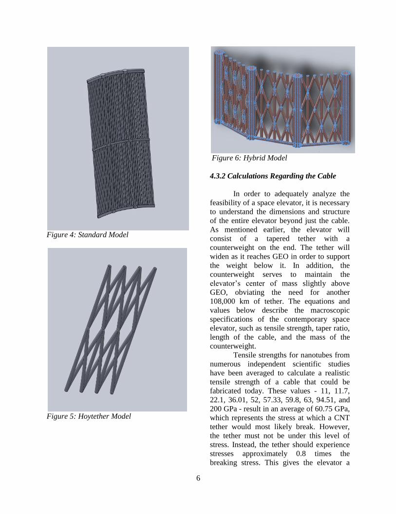
The second design, called the
Hoytether, was proposed by Robert Hoyt as
an alternative to the Standard Model [1]. It
consists of a lattice of vertical CNTs and
diagonal CNTs forming a diamond pattern.
The Hoytether design provides a possible
solution to the issue of space debris
impacting the tether. If a vertical member is
severed, the diagonal members are designed
to stretch and assume the load of the severed
CNT. In this way, the tether will be able to
adapt to and weather minor damage incurred
by space debris. The render in SolidWorks
represents a small cross-section of a
Hoytether ribbon. It is enlarged, measuring
15 mm in width and 20 mm in height. The
CNTs are 1 mm in diameter.
The third design is a Hybrid between
the Standard Model and the Hoytether. It
retains the ribs, curvature, and carbon
nanotube/epoxy composite of the first
design, but replaces the vertical nanotubes
with the Hoytether weave. However, the
Hoytether diamonds are widened to make
this Hybrid considerably lighter than the
traditional Hoytether design. While the
Hoytether allows for resistance to debris, the
tensile strength of the Standard Model is
maintained in this Hybrid through the thick
vertical ribs. This model was increased in
scale considerably, with each nanotube
having a radius of 0.5 mm. The entire height
of this section was 20 mm, and its width was
46.7 mm from end to end.
6
Figure 4: Standard Model
Figure 5: Hoytether Model
Figure 6: Hybrid Model
4.3.2 Calculations Regarding the Cable
In order to adequately analyze the
feasibility of a space elevator, it is necessary
to understand the dimensions and structure
of the entire elevator beyond just the cable.
As mentioned earlier, the elevator will
consist of a tapered tether with a
counterweight on the end. The tether will
widen as it reaches GEO in order to support
the weight below it. In addition, the
counterweight serves to maintain the
elevator’s center of mass slightly above
GEO, obviating the need for another
108,000 km of tether. The equations and
values below describe the macroscopic
specifications of the contemporary space
elevator, such as tensile strength, taper ratio,
length of the cable, and the mass of the
counterweight.
Tensile strengths for nanotubes from
numerous independent scientific studies
have been averaged to calculate a realistic
tensile strength of a cable that could be
fabricated today. These values - 11, 11.7,
22.1, 36.01, 52, 57.33, 59.8, 63, 94.51, and
200 GPa - result in an average of 60.75 GPa,
which represents the stress at which a CNT
tether would most likely break. However,
the tether must not be under this level of
stress. Instead, the tether should experience
stresses approximately 0.8 times the
breaking stress. This gives the elevator a

7
comfortable factor of safety of 1.25. Thus,
for the purposes of these calculations, the
mean stress acting on the elevator will be
48.60 GPa. However, since a sample mean
was produced, a confidence interval was
necessary in order to describe its accuracy.
To 80% confidence, it is known that the
population mean of the carbon nanotubes
that have been experimentally tested and
could be constructed today is between 29.37
and 67.82, assuming a safety factor of 1.25.
Using this range, it is possible to calculate
the probable bounds of taper ratio of a space
elevator, which end up being 2.53 and 8.55
using Equation 1 below. All ratios within
this bound are reasonable in terms of
feasibility today.
Equation 1: Taper Ratio
Ag is the cross-sectional area of the cable at
geostationary orbit in m2. As is the cross-
sectional area of the cable at sea level in m2,
which is set to 10.5 μm2. R is the distance
from the center of the Earth to sea level in
m. Rg is the distance from the center of the
Earth to geostationary orbit in m. T is the
tensile stress of the cable in Pa. is the
density of the cable in
and g is the
gravitational acceleration on Earth, 9.807
.
The taper ratio of the cable with a tensile
stress of 48.60 GPa was found to be 3.66.
For any further calculations, only the
average tensile stress and the resulting
average taper ratio will be used for the sake
of clarity and specificity.
The mass of the counterweight is
given by the following equation.
Equation 2: Counterweight Mass
mc is the mass of the counterweight in kg
and h is the height of the counterweight
above geostationary orbit at 35,786 km, in
m. However, since the mass of the
counterweight is dependent on this height, h,
counterweight masses for distances ranging
from 30,000 km to 100,000 km beyond
GEO were compiled. Parts of the analysis
are shown in the chart below and it was
decided that a total length of 116,000 km
and mass of 1375 metric tons would be the
best balance between height and mass in
terms of the ability of aeronautics agencies
to launch the elevator into space.
Table 1: Counterweight Mass vs. Height
Above Geostationary Orbit
Height beyond
GEO (km)
Mass of Counterweight
(metric tons)
30,000 5270
40,000 3910
50,000 2900
60,000 2300
70,000 1780
80,000 1380
90,000 1060
100,000 812
Finally, after determining the mass of the
counterweight and the taper ratio, as well as
setting the sea level cross-sectional area to
10.5 μm2, the following equation was used
to calculate the mass of the cable itself.
Equation 3: Cable Mass
8
me is the mass of the cable and A(r) is a
function of the cross-sectional area of the
cable based on height from the center of the
Earth. It was found that the mass of the
carbon nanotube cable would be 3438 metric
tons.
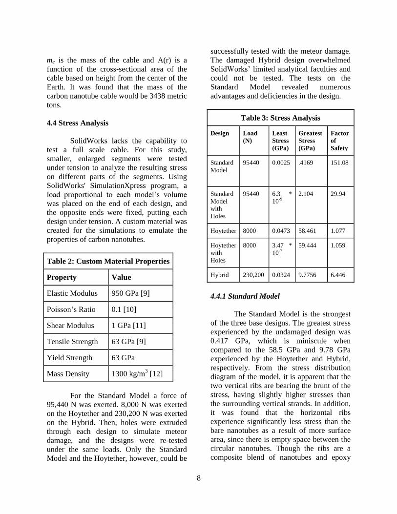
4.4 Stress Analysis
SolidWorks lacks the capability to
test a full scale cable. For this study,
smaller, enlarged segments were tested
under tension to analyze the resulting stress
on different parts of the segments. Using
SolidWorks' SimulationXpress program, a
load proportional to each model’s volume
was placed on the end of each design, and
the opposite ends were fixed, putting each
design under tension. A custom material was
created for the simulations to emulate the
properties of carbon nanotubes.
Table 2: Custom Material Properties
Property Value
Elastic Modulus 950 GPa [9]
Poisson’s Ratio 0.1 [10]
Shear Modulus 1 GPa [11]
Tensile Strength 63 GPa [9]
Yield Strength 63 GPa
Mass Density 1300 kg/m3 [12]
For the Standard Model a force of
95,440 N was exerted. 8,000 N was exerted
on the Hoytether and 230,200 N was exerted
on the Hybrid. Then, holes were extruded
through each design to simulate meteor
damage, and the designs were re-tested
under the same loads. Only the Standard
Model and the Hoytether, however, could be
successfully tested with the meteor damage.
The damaged Hybrid design overwhelmed
SolidWorks’ limited analytical faculties and
could not be tested. The tests on the
Standard Model revealed numerous
advantages and deficiencies in the design.
Table 3: Stress Analysis
Design Load
(N)
Least
Stress
(GPa)
Greatest
Stress
(GPa)
Factor
of
Safety
Standard
Model
95440 0.0025 .4169 151.08
Standard
Model
with
Holes
95440 6.3 *
10-9
2.104 29.94
Hoytether 8000 0.0473 58.461 1.077
Hoytether
with
Holes
8000 3.47 *
10-7
59.444 1.059
Hybrid 230,200 0.0324 9.7756 6.446
4.4.1 Standard Model
The Standard Model is the strongest
of the three base designs. The greatest stress
experienced by the undamaged design was
0.417 GPa, which is miniscule when
compared to the 58.5 GPa and 9.78 GPa
experienced by the Hoytether and Hybrid,
respectively. From the stress distribution
diagram of the model, it is apparent that the
two vertical ribs are bearing the brunt of the
stress, having slightly higher stresses than
the surrounding vertical strands. In addition,
it was found that the horizontal ribs
experience significantly less stress than the
bare nanotubes as a result of more surface
area, since there is empty space between the
circular nanotubes. Though the ribs are a
composite blend of nanotubes and epoxy
9
with a lower specific strength than the bare
nanotubes, the lower stress in this area
means the cable would be stable with the
regularly spaced linking system (see Figure
7 in Appendix).
When segments are removed from
the model to simulate meteor damage, the
Standard Model still proves itself to be the
strongest, experiencing a maximum stress of
2.104 GPa. However, this is still a
significant decrease in strength from the
undamaged model. The undamaged
Standard Model’s factor of safety (FOS) is
151.09, but it drops to 29.95, a fifth of its
former FOS when the model is “damaged.”
This illustrates that, as strong as though it
may be, the Standard Model is ill-equipped
to adapt to meteor damage. Any kind of
damage simply compromises the integrity of
the tether by too large a factor (see Figure 8
in Appendix).
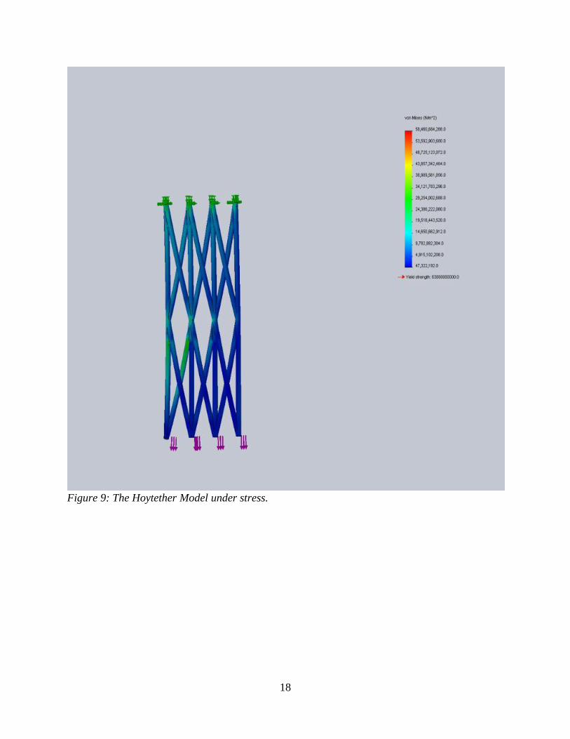
4.4.2 Hoytether
The Hoytether design was the
weakest of all the designs, experiencing
stresses up to 58.461 GPa, almost as much
as the breaking point of the CNTs. This
would be undesirable in a tether design
when there are better alternatives available.
It is important to note that most of the stress
was concentrated at the joints of the model
(see Figure 9 in Appendix).
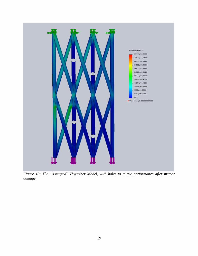
Perhaps the most significant result
from this test was the performance of the
damaged Hoytether weave. Under the same
stresses as the undamaged model and with
numerous holes in the vertical members, the
damaged model experienced a maximum
stress of only 59.444 GPa, a mere 1.6%
greater than the stress experienced by the
undamaged model. The FOS between the
undamaged and damaged models decreased
marginally, from 1.077 to 1.0598. As Hoyt
predicted, it is clear in the stress diagram
that the diagonal members successfully bore
the load after the severance of the vertical
strands. Despite its structural weakness in
comparison to other designs, it is clear that
the Hoytether is the most resilient of the
designs in the face of debris damage (see
Figure 10 in Appendix).
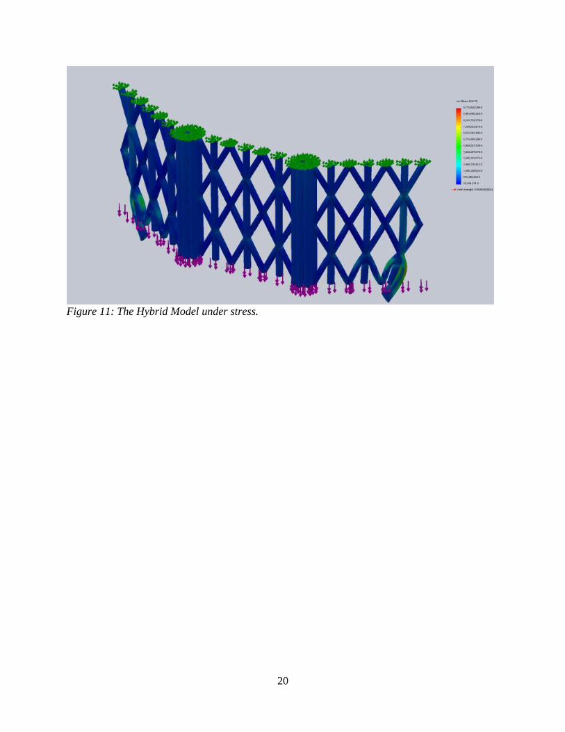
4.4.3 Hybrid Model
The Hybrid Model, though not as
strong as the Standard Model, was stronger
than the Hoytether, as evidenced by Table 3.
Unfortunately, no more data is available, as
the “meteoroid damaged” design could not
be tested. However, because it utilizes the
Hoytether’s weave between its vertical ribs,
it should retain much of the Hoytether’s
resilience in dealing with meteoroid damage.
It also employs the strong vertical ribs and
composite cross-sections of the Standard
Model, making its strength superior to the
Hoytether’s (see Figure 11 in Appendix).
4.4.4 Conclusions and Error
Before drawing any conclusions
from the data, it is imperative that readers
recognize that SolidWorks was not designed
to model nanostructures or to perform
complex stress analyses on those structures.
As such, the models and tests performed in
SolidWorks have large margins of error. It is
likely that, in the 3D rendering process, not
all variables were controlled for between
each of the three base designs. While the
comparison between damaged and
undamaged renderings of a given model is
reliable, it is unlikely the three base designs
can be compared with complete accuracy.
Nonetheless, there are numerous important
general conclusions that can be drawn from
this experiment. It is reasonable to assume
that, though vastly exaggerated through the
SolidWorks rendering, the Standard Model
is the strongest, followed by the Hybrid and
then the Hoytether. Additionally, it is highly

10
likely that the Hoytether is indeed more
resilient and adaptable than the Standard
Model when damaged by space debris.
Thus, it can fairly be concluded that the
Hybrid Model should improve upon the
strength of the Hoytether, while still
improving upon the resilience of the
Standard Model. Therefore, it would be
most advantageous to weave the tether in the
Hybrid configuration.
5. Deployment
5.1 Launch and Unspooling
Previous studies have based
launching the system off of older
technology, but rocket science has greatly
advanced in recent years. This study finds
the capabilities of the upcoming Falcon
Heavy rocket, manufactured by SpaceX, to
be suitable. The vehicle can carry 22,200 kg
to Geostationary Transfer Orbit (GTO) for
$90 million [13]. By comparison, the Space
Shuttle can carry 3,810 kg to GTO, and
estimates of launch prices range from $450
million to $1.5 billion [14]. Thus, the Falcon
Heavy costs around 2% of the Shuttle’s
costs, per kilogram. With four launches, a
very capable ship can be constructed in
GTO. The spacecraft will need chemical
thrusters and propellant in order to remain
vertical while releasing the cable (see
section 2.3). Complex spooling mechanisms
can be constructed to carefully, yet rapidly
release the cable downwards. The craft will
extend the cable while simultaneously
moving away from the Earth. Eventually,
the lower end will reach the surface and the
upper end, along with the craft itself, will
reach the full extended length to serve as a
counterweight.
The initial area of the cable at the
base will be a mere 0.105 mm2. The mass of
the counterweight will need to be 13,751 kg
and the actual mass of the spacecraft after
deployment will total 14,000 kg to keep the
center of mass far enough above GEO. The
mass of the cable itself will total 34,380 kg.
In addition, 40,000 kg of propellant will be
allocated to the spacecraft for orbital
correction and insertion. The entire mass can
be carried in 4 Falcon Heavy Launches for a
cost of $360 million.
5.2 Reinforcement
The initial ribbon will be very thin to
save mass and size in the spacecraft and
thus, can support only smaller climbers at
first. The first climbers -- roughly 200 -- will
serve to immediately reinforce the cable by
attaching new ribbons as they move
upwards. The final cable mass and area will
be 100 times the initial quantities. This
gradual process will not only enable much
larger payloads to climb, but will also serve
as protection against weaknesses in the
cable.
6. Climbers
6.1 Design
The climbers will use a simple
mechanical system to climb the cable
through the use of traction. Though others
have proposed electromagnetic propulsion
[15], this is nearly impossible for a first
elevator, and also unnecessary. The
infrastructure required is complicated and
massive. It is, however, an excellent
alternative for future elevators built using
the first, and can support humans because of
its capability to accelerate quickly. The
underside of the climber will carry solar
panels. Depending on the necessity, the
climber can be sealed and pressurized,
although preliminary climbers will not be, in
order to save mass. The rest of the climber
will carry the payload.

11
6.2 Power
Many studies suggest using the
conductive properties of carbon nanotubes
to send electricity through the cable itself
[15]. However, this system poses serious
risks; namely, a vast amount of energy will
be lost on the very long cable, and the heat
generated by this can damage the epoxy and
weaken the cable. Instead, a laser beaming
system is recommended. The climbers will
have solar panels mounted on their
undersides. A facility located on the surface
of Earth will further focus the lasers using
optics to concentrate the beam. The climbers
will then convert this energy to mechanical
power. Atmospheric distortion must also be
accounted for. Some studies suggest larger
solar panels to maintain efficiency [1].
However, this adds more mass to the
climbers, which matters greatly in the early
phases. If the lasers instead increase their
output as the climber ascends, the difference
will be accounted for by the greater intensity
of light from the laser. Energy will be lost,
but the expenditure will be reasonable.
Recent advances in lithium-ion battery
technology allow for excellent power
storage systems. This allows for operation
even during laser failures or shortages and
also enables regenerative braking, thus
saving total energy expenditure.
7. Location
7.1 Sea-going Platform
A sea-going platform will be
constructed or refurbished for use as the
space elevator’s anchor point. For example,
a floating oil rig can be repurposed. A sea-
going platform will be the most feasible for
several reasons. By international law,
international waters cannot be claimed by a
country [16]. Thus, establishing a sea-based
platform will remove much potential
political drama. In addition, mobility is a
necessity for the elevator. Orbital objects
and weather systems can be avoided if the
cable can move.
7.2 Geographical Location
A location around 2,500 kilometers
west of Ecuador, on the equator, was
selected as the best location for various
reasons. First, its location on the equator
will let the elevator move faster at lower
heights, reducing the necessary length. In
addition, this location is far less prone to
extreme weather. Tropical storms can
neither form on, nor cross the equator due to
the Coriolis Effect. In addition, the equator
in general, and particularly this location,
sees virtually no lightning and little rain or
wind, reducing weather complications [1].
8. Solutions to Other Complications
8.1 Avoiding Meteoroids, Space Debris,
and Satellites
Even debris as small as a golf ball
can demolish the entire space elevator.
However, objects in orbit can be tracked and
avoided. In addition, existing satellites must
be avoided by law, and will need to be given
a wide area to pass through unharmed [17].
This can be accomplished by moving the
anchor-barge roughly a kilometer in any
direction to send a pulse up the cable. Many
studies simply recommend moving when
necessary to avoid an object [1]. However,
these pulses can build up along the length of
the elevator, and cause chaotic motion at
certain points. Therefore, a second pulse
back to the original position is
recommended when any given pulse returns
to ground level. This will cancel out the
vibrations and allow for stable climbing on
the tether.
12
8.2 Atomic Oxygen
Atomic oxygen is a pertinent
problem when considering the construction
of a space elevator. Atomic oxygen, which
is essentially single oxygen atoms that exist
high in Earth’s atmosphere, is extremely
reactive due to the valence electrons on a
free oxygen atom. Thus, any material
exposed to atomic oxygen for substantial
periods of time will inevitably undergo
corrosion. In fact, organic elements such as
carbon are especially susceptible to the
oxygen. To remove the debilitating impacts
that atomic oxygen can have on a space
elevator, the most feasible solution is to coat
the surface area of the carbon nanotube
composite with another element that will
resist bonding with oxygen atoms. In tests
conducted by NASA and Russia using the
Hubble Space Telescope and the Mir Space
Station, it was found that aluminum, gold
and platinum are the least reactive to atomic
oxygen [18]. By conducting further tests, it
was concluded that aluminum is the best
option as it is a lightweight, non-reactive
material that could coat the space elevator
without severely harming its function or
weight. The only impact this coating would
have on the space elevator is decreasing its
strength to weight ratio a small amount,
which would be accounted for in the taper
ratio. It will not cause significant changes in
any other aspects of construction.
8.3 Radiation
Radiation must be accounted for in
the design of the elevator and cable. It is
nearly impossible for the path of the cable to
avoid exposure to some sort of radiation,
whether in the form of sun particles, galactic
cosmic rays, or the intense exposure that
will be experienced due to the Van Allen
Belts [19]. The Van Allen Belts are regions
of radiation that wrap around the earth and
fluctuate in intensity, particularly around the
equator. If a human was to travel up the
cable without proper shielding on a space
elevator, the high dosage of radiation
received will be enough to cause serious
medical problems, including death [19]. The
technology, not only humans, will be
affected by such high dosage rates. Any
sensitive equipment brought aboard the
machines may malfunction or experience
irreparable damage leading to catastrophic
failures. Hence, it is imperative that the
elevator and any climbers sent along the
cable are under consistent protection from
radiation. Aluminum is the standard for
radiation shielding due to its light weight
and the effective protection it offers.
However, any advances in this area that
would optimize the mass to shielding ratio
should be taken into consideration.
8.4 Weather
As stated above, most potentially
harmful weather will be naturally avoided
due to the anchor’s strategic location on the
equator, west of Ecuador. Other dangerous
systems can be avoided by temporarily
moving the platform elsewhere. Only calm
rain and winds will reach the elevator, and
the safety factor of the cable means that
these events will not be harmful to the
structure.
8.5 Political Considerations
Placing the anchor in international
waters enables political freedom. In
addition, the Outer Space Treaty declared
that “outer space...is not subject to national
appropriation [20].” Therefore, the political
stability of the elevator is ensured by
multiple international treaties. By the Space
Liability Convention, the operator of the
elevator will be held liable to damage
caused by it [17]. Maneuvers will need to be

13
timed to properly avoid any collisions with
satellites crossing the equatorial plane.
8.6 Effects of a Catastrophic Failure
In the event of a catastrophic failure,
wherein the cable is severed at one or more
points, the fallout will not be severe. No
matter where the cut occurs, the upper
portion of the cable will be flung outwards
into space to a relatively safe location.
Although the exact result depends upon the
height of severance, in general, higher
segments of the remaining ribbon will burn
up in the atmosphere relatively harmlessly.
Lower portions will largely land in the
ocean, and will be travelling at a low enough
velocity that very little impact damage will
occur. Thus, the effects of a catastrophic
failure will not pose serious health risks
[21].
9. Conclusions and The Future
9.1 Conclusion
This study finds that the space
elevator cable must be made from single-
walled carbon nanotubes, as they are the
only suitable material for making a space
elevator that is available today. In addition,
the cable should use the Hybrid Model, the
mix of the Hoytether and Standard Models,
for its design. The anchor on Earth should
be located west of Ecuador to avoid weather
issues and take advantage of the high radial
velocity at the Earth’s equator. After the
initial cable is deployed, additional climbers
will traverse the cable to strengthen and
repair the cable from damage, such as
atomic oxygen and meteors. The climbers
will be powered by a laser beamed from the
base to a solar panel on the climber. When
completed, the space elevator will provide a
cheap, efficient alternative method for space
exploration as opposed to the traditional
method of launching rockets. Provided that
carbon nanotubes can be mass produced in
the quantities and specifications required,
and that the economic, legal, and political
barriers can be overcome, this study
concludes that modern technology is indeed
sufficient for the construction of a space
elevator.
9.2 Future Developments
The space elevator described in this
paper will only be a first step. The first
space elevator will certainly be used to build
more complex and larger elevators. Future
developments in electromagnetic propulsion
will allow for human transport through the
Van Allen radiation belts at a high speed,
reducing exposure and allowing for human
settlements in Earth orbit. Thus, the first
veritable space city can be constructed with
a reasonably large population. It is likely
that many elevators, under different owners,
will eventually reach into space. Space
elevators will not be confined to Earth, but
rather will likely be built on the Moon and
Mars, allowing for the exploration and
development of those now-remote locations.
Asteroid mining will become a truly feasible
and profitable prospect. Space elevators will
be a stepping stone for humanity’s future
exploration and colonization of space, the
catalyst necessary to broach humanity’s
final frontier.
Acknowledgements
The authors of this paper wish to
acknowledge many individuals and
organizations for the support they provided.
Project mentor and Residential Teaching
Assistant Stephanie Tu provided assistance
and the original direction for the project.
Professor Haym Benaroya provided
invaluable insight into space structures. In
addition, the New Jersey Governor’s School

14
of Engineering and Technology and its staff
allowed for the opportunity to conduct this
study in the first place. In particular, the
authors recognize the Program Director, Dr.
Ilene Rosen, as well as Associate Director,
Dean Jean Patrick Antoine, for their
dedication to the program. The sponsors of
the program, Rutgers, the State University of
New Jersey, Rutgers School of Engineering,
the State of New Jersey, Lockheed Martin,
South Jersey Industries, Inc., and Printrbot
have backed the project indirectly. Notably,
the authors thank Rutgers University for
their hospitality.
References
[1] B. C. Edwards, “The Space Elevator,”
NIAC, 2000.
[2] B. C. Edwards. “The Space Elevator
NIAC Phase II Final Report”, Eureka
Scientific, Oakland, CA, March 1, 2003.
[3] B. C. Edwards, “Design and Deployment
of a Space Elevator,” Los Alamos National
Library, Los Alamos, NM, Nov. 17, 2000.
[4] P. A. Swan et al., “Space Elevators: An
Assessment of the Technological Feasibility
and the Way Forward,” IAA, Paris, France,
Oct. 2013.
[5] R. E. Roman, K. K. Kwan, and S. W.
Cranford, “Mechanical Properties and
Defect Sensitivity of Diamond
Nanothreads,” NE Univ., Boston, MA. Feb.
18, 2015.
[6] “Carbon Nanotube Composites,”
Polymer Characterization. [Online].
Available:
http://coecs.ou.edu/brian.p.grady/nanotube.h
tml.
[7] K. Talukdar and A. K. Mitra, “Molecular
Dynamics Simulation Study on the
Mechanical Properties and Fracture
Behavior of Single-Wall Carbon
Nanotubes,” in Carbon Nanotubes -
Synthesis, Characterization, Applications,
Durgapur, India: Dept. Physics, Nat. Inst.
Tech., 2011, ch. 15.
[8] “Quicklinks,” Swiss Nanoscience
Institute, Basel, Switzerland. [Online].
Available:
http://www.nanoscience.ch/nccr/nanoscienc
e/pictures/gallery_01/gallery_01_03#pics_0
2.
[9] M. Yu, et al., “Strength and Breaking
Mechanism of Multiwalled Carbon
Nanotubes Under Tensile Load,” Science,
vol. 287, pp. 637-640, Jan. 28, 2000.
[10] W. Chen, H. Cheng, and Y. Liu,
“Radial Mechanical properties of single-
walled carbon nanotubes using modified
molecular structure mechanics,”
Computational Materials Science, vol. 47,
pp. 985-993, Feb. 2010.
[11] J. Salvetat, et al., “Elastic and Shear
Moduli of Single-Walled Carbon Nanotube
Ropes,” American Physical Society, Phys.
Rev. Lett. 82, 944, Feb. 1, 1999.
[12] P. K. Aravind, “The physics of the
space elevator,” Worcester Polytechnic
Institute, Worcester, MA, 2007.
[13] “Capabilities & Services,” SpaceX.
[Online]. Available: http://www.spacex
.com/about/capabilities.
[14] D. R. Jenkins, Space Shuttle: The
History of the National Space
Transportation System: The First 100
Missions, 3rd ed. Minneapolis, MN:
Voyageur Press, 2006

15
[15] D.V. Smitherman, “Space Elevators: an
Advanced Infrastructure for a New
Millennium,” Marshall Space Flight Center,
Huntsville, AL, Aug. 2000
[16] “Overview - Convention & Related
Agreements,” UN News Center. [Online].
Available:
http://www.un.org/depts/los/convention_agr
eements/convention_overview_convention.h
tm.
[17] “United Nations Office for Outer Space
Affairs,” Liability Convention. [Online].
Available:
http://www.unoosa.org/oosa/en/ourwork/spa
celaw/treaties/introliability-convention.html.
[18] D. Dooling and M. M. Finckenor,
“Material Selection Guidelines to Limit
Atomic Oxygen Effects on Spacecraft
Surfaces,” Marshall Space Flight Center,
Huntsville, AL, June, 1999.
[19] “A. M. Jorgensen, S. E. Patamia, and B.
Gassend, “Passive radiation shielding
considerations for the proposed space
elevator,” in Acta Astronautica, vol. 60, pp.
198-209, Feb. 2007.
[20] “United Nations Office for Outer Space
Affairs,” The Outer Space Treaty. [Online].
Available:
http://www.unoosa.org/oosa/en/ourwork/spa
celaw/treaties/introouterspacetreaty.html.
[21] B. Gassend, “Fate of a Broken Space
Elevator.,” in SESI Conference Series, vol.
001, Mass, Inst. Tech. Comp. Sci. & Art.
Intell. Lab., Cambridge, MA, 2005.

16
Appendix
Figure 7: The Standard Model is under stress with the blue epoxy composite ribs experiencing
less stress. The purple arrows are loads attached to the model, while green arrows are fixed
points on the model. As per the metric on the right of the image, blue regions experience less
stress than green region.

17
Figure 8: The damaged Standard Model design has a large hole in it to mimic performance after
meteor damage. While it looks blue, the colors on the metric correspond to different values as
those in Figure 7.
.
18
Figure 9: The Hoytether Model under stress.
19
Figure 10: The “damaged” Hoytether Model, with holes to mimic performance after meteor
damage.
20
Figure 11: The Hybrid Model under stress.