space environment effects on silicone seal materials · since silicone rubber is the only class of...
TRANSCRIPT

Henry C. de Groh IIIGlenn Research Center, Cleveland, Ohio
Christopher C. DanielsThe University of Akron, Akron, Ohio
Joyce A. Dever and Sharon K. MillerGlenn Research Center, Cleveland, Ohio
Deborah L. WatersASRC Aerospace Corporation, Cleveland, Ohio
Joshua R. Finkbeiner, Patrick H. Dunlap, Jr., and Bruce M. SteinetzGlenn Research Center, Cleveland, Ohio
Space Environment Effects onSilicone Seal Materials
NASA/TM—2010-216332
July 2010
https://ntrs.nasa.gov/search.jsp?R=20100029591 2018-06-03T10:56:29+00:00Z

NASA STI Program . . . in Profi le
Since its founding, NASA has been dedicated to the advancement of aeronautics and space science. The NASA Scientifi c and Technical Information (STI) program plays a key part in helping NASA maintain this important role.
The NASA STI Program operates under the auspices of the Agency Chief Information Offi cer. It collects, organizes, provides for archiving, and disseminates NASA’s STI. The NASA STI program provides access to the NASA Aeronautics and Space Database and its public interface, the NASA Technical Reports Server, thus providing one of the largest collections of aeronautical and space science STI in the world. Results are published in both non-NASA channels and by NASA in the NASA STI Report Series, which includes the following report types: • TECHNICAL PUBLICATION. Reports of
completed research or a major signifi cant phase of research that present the results of NASA programs and include extensive data or theoretical analysis. Includes compilations of signifi cant scientifi c and technical data and information deemed to be of continuing reference value. NASA counterpart of peer-reviewed formal professional papers but has less stringent limitations on manuscript length and extent of graphic presentations.
• TECHNICAL MEMORANDUM. Scientifi c
and technical fi ndings that are preliminary or of specialized interest, e.g., quick release reports, working papers, and bibliographies that contain minimal annotation. Does not contain extensive analysis.
• CONTRACTOR REPORT. Scientifi c and
technical fi ndings by NASA-sponsored contractors and grantees.
• CONFERENCE PUBLICATION. Collected papers from scientifi c and technical conferences, symposia, seminars, or other meetings sponsored or cosponsored by NASA.
• SPECIAL PUBLICATION. Scientifi c,
technical, or historical information from NASA programs, projects, and missions, often concerned with subjects having substantial public interest.
• TECHNICAL TRANSLATION. English-
language translations of foreign scientifi c and technical material pertinent to NASA’s mission.
Specialized services also include creating custom thesauri, building customized databases, organizing and publishing research results.
For more information about the NASA STI program, see the following:
• Access the NASA STI program home page at http://www.sti.nasa.gov
• E-mail your question via the Internet to help@
sti.nasa.gov • Fax your question to the NASA STI Help Desk
at 443–757–5803 • Telephone the NASA STI Help Desk at 443–757–5802 • Write to:
NASA Center for AeroSpace Information (CASI) 7115 Standard Drive Hanover, MD 21076–1320

Henry C. de Groh IIIGlenn Research Center, Cleveland, Ohio
Christopher C. DanielsThe University of Akron, Akron, Ohio
Joyce A. Dever and Sharon K. MillerGlenn Research Center, Cleveland, Ohio
Deborah L. WatersASRC Aerospace Corporation, Cleveland, Ohio
Joshua R. Finkbeiner, Patrick H. Dunlap, Jr., and Bruce M. SteinetzGlenn Research Center, Cleveland, Ohio
Space Environment Effects onSilicone Seal Materials
NASA/TM—2010-216332
July 2010
National Aeronautics andSpace Administration
Glenn Research CenterCleveland, Ohio 44135

Acknowledgments
The authors would like to acknowledge and praise the efforts of our colleagues who contributed to this work:Daniel A. Scheiman for IR spectroscopy; Richard Tashjian for mechanical support; Bruce Banks and
Lawrence Kren for help with Tank 9 exposures; and Marta Bastrzyk for helpwith presentation of adhesion data.
Available from
NASA Center for Aerospace Information7115 Standard DriveHanover, MD 21076–1320
National Technical Information Service5301 Shawnee Road
Alexandria, VA 22312
Available electronically at http://gltrs.grc.nasa.gov
Trade names and trademarks are used in this report for identifi cation only. Their usage does not constitute an offi cial endorsement, either expressed or implied, by the National Aeronautics and
Space Administration.
Level of Review: This material has been technically reviewed by technical management.

NASA/TM—2010-216332 iii
Contents
1.0 Introduction ............................................................................................................................................ 2 2.0 Experimental Procedures ........................................................................................................................ 5
2.1 Space Simulations and Exposures ................................................................................................. 5 2.1.1 Vacuum and Methods to Measure and Lower Outgassing ............................................... 5 2.1.2 Atomic Oxygen ................................................................................................................. 6 2.1.3 Vacuum Ultraviolet/Near Ultraviolet Radiation ............................................................. 10 2.1.4 Particle Radiation ............................................................................................................ 12
2.2 Methods to Decrease Adhesion ................................................................................................... 12 2.3 Seal Performance ........................................................................................................................ 13
2.3.1 Seal Leak Rate ................................................................................................................ 13 2.3.2 Seal Adhesion ................................................................................................................. 13 2.3.3 Compression Set ............................................................................................................. 15
3.0 Results .................................................................................................................................................. 16 3.1 Appearance ................................................................................................................................. 16 3.2 Leak Rate .................................................................................................................................... 19 3.3 Residual Adhesion ...................................................................................................................... 20 3.4 Compression Set ......................................................................................................................... 23 3.5 Vacuum Outgassing .................................................................................................................... 25
4.0 Conclusions .......................................................................................................................................... 26 Appendix A.—Acronyms ........................................................................................................................... 27 References ................................................................................................................................................... 28


NASA/TM—2010-216332 1
Space Environment Effects on Silicone Seal Materials
Henry C. de Groh III National Aeronautics and Space Administration
Glenn Research Center Cleveland, Ohio 44135
Christopher C. Daniels University of Akron Akron, Ohio 44325
Joyce A. Dever and Sharon K. Miller National Aeronautics and Space Administration
Glenn Research Center Cleveland, Ohio 44135
Deborah L. Waters ASRC Aerospace Corporation
Cleveland, Ohio 44135
Joshua R. Finkbeiner, Patrick H. Dunlap, Jr., and Bruce M. Steinetz National Aeronautics and Space Administration
Glenn Research Center Cleveland, Ohio 44135
Executive Summary
A Low Impact Docking System (LIDS) was being developed by the NASA Johnson Space Center (JSC) to support future missions of the Crew Exploration Vehicle (CEV). It was planned that LIDS would use a set of redundant silicone seals to help contain cabin air during dockings between CEV and the International Space Station (ISS). The NASA Glenn Research Center (GRC) supported the development of the LIDS docking system by developing the main interface seals and determining the durability of candidate seal materials in the space environment. The sealing surfaces are exposed to the space environment when vehicles are not docked. In space, the seals will be exposed to temperatures of between 125 and –75 °C, vacuum, atomic oxygen (AO), particle and ultraviolet (UV) radiation, and micrometeoroid and orbital debris (MMOD). Since silicone rubber is the only class of space flight-qualified elastomeric seal material that functions across the expected temperature range, NASA GRC focussed on three silicone elastomers: two provided by Parker-Hannifin Corporation (S0899-50 and S0383-70) and one from Esterline Corporation (ELA-SA-401).
The effects of AO, UV and electron particle radiation, and vacuum on the properties of these three elastomers were examined. Exposure conditions were developed to simulate the environment of low-Earth orbit (LEO) so the durability of these materials in outer space could be estimated. Exposure levels were set with NASA mission timelines in mind, and to determine exposure limits and material failures. This work supports the development of a specific seal for LIDS by relating the measured properties to seal performance. Critical seal properties such as leakage, adhesion, and compression set were measured before and after simulated space exposures.
One challenge for elastomeric seals in such applications is that adhesion makes it difficult to separate spacecrafts when undocking. The elastomers exposed to AO underwent chemical and physical changes which resulted in a SiOx-rich layer at the surface. This layer was beneficial since it decreased the natural adhesive properties of the elastomer using modest levels of AO exposure. The adhesion dropped by a factor of 10 with an AO exposure of about 1019 atoms/cm2, and to negligible levels (<1 psi) for S0383-70 and ELA-SA-401 at doses of 1020 atoms/cm2. Seal-on-seal adhesion was particularly high for S0899-50,

NASA/TM—2010-216332 2
and remained high (~10 psi) even after relatively high AO exposures (71021 atoms/cm2). Further AO exposures however result in increased leakage. All three elastomers sealed well at AO exposures <71021 atoms/cm2; but leak rate rose extremely rapidly (increasing between 1 and 3 orders-of-magnitude) between AO exposure levels of 71021 and 1022 atoms/cm2. When exposed to AO only, S0899-50 and ELA-SA-401 failed (leakage >10–4kg/day) at AO exposures >1022 atoms/cm2; S0383-70 failed at AO exposures >31022 atoms/cm2. The amount of compression set suffered by the elastomers also increased with AO exposure, but at rather high levels of AO (>1022 atoms/cm2). Compression set about doubled at AO exposures of >31022 atoms/cm2 compared to as-received.
All UV-exposed specimens were first exposed to 5.81021 atoms/cm2 AO. Seal leakage increased gradually with increasing levels of UV (combined with the constant AO exposure). The S0899-50 elastomer was particularly sensitive to UV exposure, failing after about 500 ESH (equivalent Sun hours) of UV exposure (plus the AO). The other elastomers, ELA-SA-401 and S0383-70, were nearing failure limits when UV exposures were stopped at about 1500 ESH (plus AO). The level of adhesion for ELS-SA-401 and S0383-70 were already nearly zero after the AO, but adhesion for S0899-50 was still high (10 psi) after AO but before the UV exposure. The subsequent UV exposure of 1500 ESH eliminated most S0899-50 adhesion (<1 psi). The tests indicated UV exposure also exacerbated compression set, which increased an average of about 40 percent for all three of the compounds after 300 ESH.
Even though an AO treatment could mitigate adhesion, there were concerns that the AO might change the elastomer’s structure detrimentally thus causing more outgassing. Further investigations revealed that outgassing in ELA-SA-401 was unchanged after AO, and decreased slightly for S0383-70 after AO exposure of 1020atoms/cm2. Braycote grease coated S0383-70 seals also passed outgassing even though outgassing increased slightly (TML and CVCM increasing ~0.01 percent).
No negative consequences of exposure to up to 1.3 Mrad (Si) electron radiation were observed. Compression set appeared to decline a bit, decreasing the most in the S0899-50 compound.
In conclusion, the S0899-50 silicone was determined to be inadequate for LIDS seal applications due to high adhesion and intolerance to UV, but both S0383-70 and ELA-SA-401 seals were adequate.
1.0 Introduction
In support of the development of a new docking system for NASA, concepts were explored to produce a leak-free seal between docking spacecraft (Ref. 1), such as the Crew Exploration Vehicle, the International Space Station (ISS) and NASA’s lunar module Altair. Depending on application, the LIDS system was designed to be either androgynous (requiring seal-on-seal interface) or standared design (using more typical seal-on-flange interface) (Refs. 2 to 4). This paper presents comprehensive evaluation of three candidate materials being considered for the LIDS. The considered materials are all silicone-based elastomers, two from Parker-Hannifin Corporation: compounds S0383-70 and S0899-50; and one manufactured by Esterline Corporation: compound ELA-SA-401. Figures 1 and 2 show the location of the main interface seal of the LIDS.
Silicones were developed during World War II, are semi-organic, and have a wide range of physical forms. Silicones consist of high molecular weight chains of alternating silicon and oxygen atoms; these chains are modified by various organic side groups attached to the silicon atoms, and by crosslinking of primary chains (Ref. 5). Basic discussions of silicone o-ring elastomers relating to testing, aging, and properties can be found in Parker O-ring Handbook (Ref. 6). One of the primary reasons silicone-based elastomers were selected as candidates was their flexibility at low temperatures. Most other elastomers become too firm near the low temperatures the LIDS seals are required to operate. Use-temperature range for the main seal on LIDS was –50 to 50 °C with exposure temperatures between –75 to 125 °C. The behavior of elastomeric seals at low temperatures has been examined by Weise et al. (Ref. 7) who found, at a well defined low “critical temperature”, a sharp rise in leak rate due to shrinkage of the elastomer. The effects of temperature on leakage and compression set were found to be reversible, and the critical temperature for the silicone rubber examined was –63 °C (Ref. 7).

NASA/TM—2010-216332 3
LIDS primary seal Metal flange
Location of LIDS main interface seal
Figure 1.—The LIDS assists the coupling of two vehicles in space; elastomer
seals between vehicles prevent air loss from inside the cabin.
Figure 2.—Drawing of a manned capsule docking with ISS; LIDS enables the coupling of the
two together; the elastomer of the LIDS primary seal stops air from leaking out after docking.

NASA/TM—2010-216332 4
While a particular space vehicle is not docked, the seal material is exposed, either to various atmospheric conditions at the launch pad or to outer space. We have examined as-received properties, as well as the effects of various space environments which include vacuum, atomic oxygen, ultraviolet and electron particle radiations, and micrometeoroid and orbital debris (MMOD). The effects of MMOD are presented elsewhere (Refs. 8 and 9). Use specifications defining the exposure environments were taken from the Constellation Program Design Specifications (Ref. 10). Other factors which helped define the specific exposures used in this study included the capabilities of the facilities and the response of the elastomer.
Several NASA missions have suffered from the effects of volatile materials condensing on sensitive parts of spacecrafts. For this reason strict outgas specifications in terms of total mass loss (TML) and collected volatile condensable materials (CVCM) in a vacuum are required on materials bound for space. Outgassing data for various spacecraft materials has been collected by Campbell and Scialdone (Ref. 11).
Banks et al. have examined the effects of the AO present in low-Earth orbit on silicone elastomers and found that AO oxidizes the surface of the silicone, creating a thin layer of silica and that glassy SiOx-based contaminant coatings result on nearby surfaces (Refs. 12 and 13). Banks et al. showed synergistic effects between UV radiation and AO with respect to silicone contamination effects, with the UV exacerbating deleterious AO induced silicone contamination (Ref. 13). With sufficient AO exposure, tensile strains were shown to lead to cracking and further, deeper oxidation (Refs. 14 and 15). The development of an SiOx-rich surface layer due to AO in space and subsequent cracking was confirmed by the Spacecraft Silicones Experiments flown on Materials International Space Station Experiments (MISSE) 2 and 4 (Ref. 16). Dever and de Groh examined the effects of UV, AO, and thermal cycling on Teflon (DuPont) and aluminized Teflon thermal shield materials being considered for the Hubble Space Telescope; they found that rapid thermal cycling caused delamination of the aluminum coating, that UV embrittled the surface of uncoated Teflon, and AO eroded uncoated Teflon (Ref. 17).
Dever, Banks and Yan, have examined how irradiance spectra and light intensity of vacuum UV exposures effect a rubbery silicone adhesive (DC93-500); showing degradation increases with increases in UV wavelength at equivalent incident energy fluence and that degradation was largely insensitive to vacuum UV light intensity for intensities up to 5.5 times that of the Sun in the 115 to 200 nm wavelength range (Ref. 18). Christensen et al. simulated the combined effects of AO and vacuum ultraviolet (VUV) on S383 silicone in preparations for its use as a sealant between Common Berthing Mechanism (CBM) elements on ISS. Exposures in this work were up to 181 equivalent on orbit hours; subsequent helium leak tests made at moderate seal compressions resulted in low leak rates, which ultimately led to the S383 silicone’s qualification for use on the CBM-to-CBM molded seals on Space Station (Ref. 19). In August 1997 the Shuttle mission STS-85 included a group of experiments known as the Evaluation of Space Environment and Effects on Materials. Included among these experiments were specimens of Parker’s silicone S383-70 which were exposed to an AO fluence of approximately 1020 atoms/cm2 (Ref. 20). Post-flight silicone had a slight mass increase, reported to be due to contamination from other specimens, and emittance and absorptance values of 0.91 and 0.75, respectively (Ref. 20).
Radiation can cause the formation of free radicals and ions in polymers and adhesives; inducing cross-linking, chain scission, chain polymerization, block copolymerization, unsaturation, and chain transfer. According to (Ref. 21), plastics less resistant to radiation, such as Teflon, are severely damaged at radiation levels of 106 rad. The more radiation durable plastics, such as polystyrene and polyimide (Kapton) (DuPont), are usable with exposures up to 1010 rad (Ref. 21). Natural rubber looses about half of its tensile strength after about 2107 rad. Electrical breakdown exposure dose for silicone rubber was found to be 41018 n/cm2; this neutron fluence is approximately equivalent to about 1010 rad. Changes in elongation in silicone began after 106 rad; changes in the tensile strength of silicone resin began at about 5107rad (Ref. 21). The data from the literature indicate that the docking seal will not be damaged by exposures less than 106 rad; noticeable damage is likely to begin at 107 rad. The durability of rubbers to radiation is highly dependent on the presence of fillers added to the compound (Ref. 21).

NASA/TM—2010-216332 5
The effects of the space environment at synchronous orbit on Kapton and Teflon were considered by TRW’s Defense and Space Systems Group (Ref. 22). Synchronous orbit is about 36,000 km from the Earth’s surface (Space Station altitude is ~350 km). At this altitude Reference 22 divides the proton environment into: plasma-sheet protons; geomagnetically trapped (radiation belt) protons; and solar flare protons. Electron exposures of significance are noted as high energy geomagnetically trapped (Van Allen belt) electrons; and plasma-sheet electrons. To simulate a 5 year mission, Reference 22 used exposures of
Van Allen belt: 21015 e/cm2, 80 keV electrons, plus 1.51015 e/cm2, 200 keV electrons;
Plasma–Sheet electrons: 1017 e/cm2, 7 keV electrons;
Plasma–Sheet protons: 1.61016 p/cm2, 27 keV protons;
Radiation belt and Solar Flare electrons: too small to include.
According to Reference 22, fluxes for protons in the radiation belt and due to solar flares are ~107 p/cm2sec (<0.25 MeV) and ~104 p/cm2sec (<10 MeV) respectively; much less than the plasma sheet proton and electron fluxes noted above. Thus radiation belt and solar flare protons were omitted. The details of TRW’s analysis are being mentioned to emphasize that various doses are highly dependent on the characteristics of the mission. The lunar missions we are considering in this work spend less than 5 hr at altitudes near the synchronous orbit altitude TRW was considering. Using the synchronous orbit conditions laid out in Reference 22, the radiation dose for a 12-year mission would be about 600,000 Mrad. The 12-year mission we consider in this work, following the protocols from Reference 10, results in a radiation dose of only 0.6 Mrad because radiation levels are much lower in LEO compared to synchronous orbit.
The space environment imposes a very high vacuum level. In general, the effects of vacuum on a material should be examined before its use in space. Prior work with silicone-based elastomers has shown these materials to be highly durable in vacuum environments, (Refs. 2, 6, and 23) thus the effects of vacuum where not directly examined in this study.
Another aspect of space is the threats imposed by micrometeoroids and orbital debris (MMOD). Small pieces of orbiting trash and galactic ice traveling at speeds between 7 and 25 km/s are typical. The level of damage that these hypervelocity particles can cause can be devastating. An extensive campaign to examine the level of damage, and expected frequency of such impacts on LIDS seals is underway by the authors, with results to date reported in References 8 and 9.
2.0 Experimental Procedures
Tests were done on three elastomers: two from Parker with compound designations of S0383-70 and S0899-50, and one from Esterline made from ELA-SA-401. Compound and processing details are proprietary; however, all are peroxide cured silicone-based elastomers. Materials in the forms of #2-309 o-rings and 0.21 in. thick sheet were procured. O-rings were used for seal leak and compression set testing, and short 0.36 in. diameter cylindrical buttons were made from the sheet material and used to test elastomer-to-elastomer adhesion.
2.1 Space Simulations and Exposures
2.1.1 Vacuum and Methods to Measure and Lower Outgassing
Upon delivery from the manufacturer, all in coming elastomers were outgas tested. Outside vendors are used for these tests, which follow ASTM Standard Designation: E 595-93 (Ref. 24). Some incoming material failed outgas testing and was returned to the manufacturer. Problems with outgassing have been tracked back to improper curing and rectified. Basic outgas results are being presented elsewhere (Ref. 25). The combined effects of vacuum and the other exposures are also tested since UV exposures impose a high vacuum.

NASA/TM—2010-216332 6
When elastomer seals are used in space, it is important for them to be stable, and have a low Total Mass Loss (TML) and a low level of Collected Volatile Condensable Materials (CVCM). The outgassing requirements for the LIDS seal are TML <1 percent and CVCM <0.1 percent. Since it is desirable for TML and CVCM to be as low as possible, an experiment was done to lower the TML and CVCM of the two primary elastomers being considered for LIDS (Parker’s S0383-70 and Esterline’s ELA-SA-401). The treatments mentioned next were done in specimens already post-cured per manufacturer specifications.
A set of eight o-rings were used in a campaign to lower TML and CVCM for Parker S0383-70 and Esterline ELS-SA-401 materials: one #2-309 o-ring and three #2-106 o-rings of each compound were tested. The #2-309 o-rings were for post-treatment leak flow testing in the Small Scale Flow Fixture (SSFF). The #2-106 o-rings were used for post-treatment outgas testing at Orange County Material Test Laboratories. The treatment used to increase compound stability was: a four-day bake under vacuum (810–6 torr) at 205 °C, then an AO treatment of 4.91020 atoms/cm2. The four-day vacuum bake was to draw off volatiles from the compounds; the AO treatment was then used to seal the surface, encasing the bulk of the material in a thin SiOx-rich shell.
Another set of #2-106 o-rings were coated with space flight-qualified grease (Braycote) to determine if the greased elastomers could pass outgas testing. First the o-rings were cleaned, dried, and weighed, then, while wearing gloves, were coated with Braycote * 601 EF perfluoroether grease; Lot #137452, DOM: 062608, made by Castrol, and reweighed. The amount of grease on the o-rings was 121 g/m2 of o-ring surface. Another set of #2-106 o-rings was exposed to 1020 atoms/cm2 AO to determine the effect of AO alone on outgassing.
2.1.2 Atomic Oxygen
The atomic oxygen present in low-Earth orbit was simulated using three facilities. SPI Plasma Prep II etchers (known as “plasma ashers”) which provide an isotropic AO plasma, were used for longer exposures; the Directed Beam Facility was used for shorter exposures; and the Tank 9 facility was used to exposure large-scale LIDS seals. Each candidate elastomer was exposed three times in the plasma ashers; various tests of leak rate, adhesion, and compression set were accomplished between most of the exposures. Target fluences for these plasma asher exposures were 11022, 1.51022, and 3.51022 atoms/cm2. A series of two exposures in the Directed Beam Facility yielded exposures of between 1.51021 and 7.61021 atoms/cm2. Several exposures were performed in Tank 9 at levels between 11018 and 11020 atoms/cm2. In general, specimens were laying down, so that the underside of the specimen was not exposed to AO. Kapton witness coupons were used to measure the level of AO fluence and calibrate the AO exposure facilities. The specific exposures of the various buttons and o-rings used in this study to examine the effects of space on the elastomers are provided in Tables 1 to 3. The uncertainty of fluence measurements for exposures >91018 atoms/cm2 was 10 percent; uncertainty was 20 percent for AO exposures <91018 atoms/cm2.
Atomic oxygen exposure fluences can be converted to “simulated years of space atomic oxygen” using the fluence to time in LEO at ISS altitude conversion factor of 1 year AO = 51021 atoms/cm2. This conversion is from Reference 10; other experts in this area have determined the conversion between AO fluence and time in LEO during solar maximum (2013) to be closer to 3.41021 atoms/cm2 (Ref. 26).
The AO in space frequently erodes materials, causing mass loss. Silicones however do not usually lose much mass since adhering SiO2 phases typically form; but for completeness, mass measurements before and after AO exposures made.
2.1.2.1 Measurement of Sample Mass
All of the isotropic AO-exposed seal samples and the polyimide Kapton fluence witnesses were fully dehydrated for at least 48 hr in a vacuum of 8 to 13 Pa (60 to 100 mtorr) prior to weighing and subsequent exposure to atomic oxygen. Post-exposure samples also were dehydrated for the same length of time prior to weighing. The Kapton witness coupon was quickly weighed on a Mettler M3 microbalance after

NASA/TM—2010-216332 7
dehydration to minimize errors in mass due to water absorption (Ref. 27) and the seal samples were weighed in the same manner using a Sartorius balance. The change in mass of the polyimide Kapton was used to calculate the effective fluence (number of atoms of oxygen arriving per square centimeter over the test duration) by inserting the value of the mass change into Equation (1):
E
AMF
*
/
(1)
where: F = Fluence (atoms/cm2) M = Mass loss of polyimide Kapton H (g) A = Area of polyimide Kapton H exposed to atomic oxygen (cm2) = Density of polyimide Kapton H (1.42 g/cm3) E = Erosion yield for polyimide Kapton H in LEO (310–24 cm3/atom)
A more detailed description of this procedure is described in ASTM E-2089-00 for Standard Practices for Ground Laboratory Atomic Oxygen Interaction Evaluation of Materials for Space Applications (Ref. 28). Mass loss due to AO exposure is typically very low in silicone-based rubbers, thus elastomer specimens exposed using the directed beam were not weighed.
2.1.2.2 Isotropic Radio Frequency Atomic Oxygen Plasma
Two SPI Supplies Plasma Prep II facilities operated in a partial air pressure environment were used to provide the isotropic atomic oxygen arrival. The facilities operate by using radio frequency (RF) (13.56 MHz) to create a discharge between two electrodes which surround a glass reaction chamber. A thermal plasma is produced which is at an energy of approximately 0.1 eV. The plasma contains atomic and excited species as well as molecules, ions, electrons and UV radiation. The amounts and intensity of these have not been determined. Typical vacuum chamber pressure during operation was 16 to 27 Pa (120 to 200 mtorr). Temperature measured in past experiments was 65 °C (Ref. 29). The two facilities were operated in parallel. One contained an aluminum machined sample tray containing the Parker-Hannifin S0383-70 seal samples and the other contained a similar tray with the Parker-Hannifin S0899-50 seal samples. Each tray contained in addition to the seals its own polyimide Kapton fluence witness and a sapphire window (2.54 cm diameter) for a contamination witness. Fluences resulting from exposures of S0899-50 were estimated from Kapton witness coupons exposed alone in a rate test prior to the exposure; this was done because sapphire and Kapton witnesses indicated significant contamination and outgassing during AO exposure of S0899-50 (negligible levels of contamination and outgassing were observed during the exposures of S0383-70 and ELA-SA-401). The transmittance and reflectance as a function of wavelength from the sapphire contamination witness samples were measured prior to and after exposure using a Perkin-Elmer Lambda-19 spectrophotometer. The measurements were made to look for evidence of a coating being deposited on the surface (changing of the reflectance or transmittance) which would be indicative of a contaminant being deposited on the surface from outgassing seals. Sapphire witnesses were only used in the initial AO exposures in the ashers to determine the level of contamination and outgassing from the different compounds.
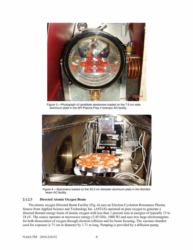
Figure 3 shows the Al plate with the specimens and witness coupons loaded in the isotropic AO facility.
NASA/TM—2010-216332 8
Figure 3.—Photograph of candidate elastomers loaded on the 7.6 cm wide
aluminum plate in the SPI Plasma Prep II isotropic AO facility.
Figure 4.—Specimens loaded on the 20.3 cm diameter aluminum plate in the directed
beam AO facility.
2.1.2.3 Directed Atomic Oxygen Beam
The atomic oxygen Directed Beam Facility (Fig. 4) uses an Electron Cyclotron Resonance Plasma Source from Applied Science and Technology Inc. (ASTeX) operated on pure oxygen to generate a directed thermal energy beam of atomic oxygen with less than 1 percent ions at energies of typically 15 to 18 eV. The source operates at microwave energy (2.45 GHz, 1000 W) and uses two large electromagnets for both dissociation of oxygen through electron collision and for beam focusing. The vacuum chamber used for exposure is 71 cm in diameter by 1.71 m long. Pumping is provided by a diffusion pump,

NASA/TM—2010-216332 9
mechanical pump and roots-type blower that operate on Fomblin (perfluorinated polyether) oil. The base pressure of the vacuum chamber is typically 2e-6 to 5e-5 torr, but during operation can range from 2e-4 to 8e-4 torr depending on the oxygen gas flow rate. In addition to producing atomic oxygen, the source also produces VUV radiation at 130 nm at an intensity of approximately 150 Suns. Seal samples were inserted into recessed grooves cut into a circular plate that was mounted in the facility for exposure. Five polyimide Kapton fluence witness samples were also included on the plate to provide information on the atomic oxygen fluence as well as the spatial distribution. A more detailed description of the facility is contained in Reference 30. Figure 4 shows a batch of specimens loaded on the exposure plate in the Directed Beam Facility.
2.1.2.4 Full-Scale Seal Tank 9 Exposures
Another atomic oxygen plasma generator at NASA GRC is located in a large steel rectangular vacuum chamber known as Tank 9, and is shown in Figure 5. An RF power supply is used to create an oscillating potential between two large vertical plates in the presence of a partial pressure of air, usually about 7 mtorr, thereby generating the oxygen-rich plasma shown in Figure 5(b). Tank 9 delivers a flux of approximately 1.261019 atoms/cm2 per hour. This flux is not homogeneous throughout the tank. Prior to exposures the flux in Tank 9 is characterized using Kapton witness coupons. A map of iso-flux lines is made to better estimate flux levels for particular specimens located in different places within the tank, and to plan rotation cycles for large specimens to insure even levels of exposure. A test of Tank 9 using temperature-sensitive adhesive strips indicated a peak temperature of 853 °C for a 24 hr exposure. The peak temperature during full-scale exposures is expected to be much less than this since exposures last for less than 7 hr each; after the first 6.4 hr exposure, the system is powered down, allowed to cool, and the seal rotated 90° and exposed for another 6.4 hr for a total exposure of 1020 atoms/cm2.
When exposing full-scale seals in Tank 9 many button specimens were also exposed to verify expected decreases in adhesion with AO treatment. Seals for MMOD studies were exposed in Tank 9.
(a) (b)
Figure 5.—Tank 9, about 5 ft tall by 3 ft wide, Tank 9 is used to expose large items to atomic oxygen; (a) Tank 9 exterior, (b) a view into the tank through one of the round ports during an exposure, showing the reddish glow of the plasma and various specimens attached to the vertical plate.

NASA/TM—2010-216332 10
2.1.3 Vacuum Ultraviolet/Near Ultraviolet Radiation
The VUV/Near Ultraviolet (NUV) exposure facility (Fig. 6) uses a cryogenic vacuum pumping system in order to conduct exposure of samples under high vacuum conditions. VUV and NUV light beams are orthogonal to one another, illuminating a sample plate tilted 30° from vertical to receive simultaneous exposure to both beams (Fig. 6(b)).
The light source for VUV exposure was a 30-W deuterium lamp with a magnesium fluoride end-window (Hamamatsu Model L7293) which provided a lower cut-off wavelength of 115 nm. This VUV source is situated on a vacuum port that can be isolated from the sample chamber. Every 48 to 72 hr, exposures were briefly interrupted while the VUV source was removed from the facility, cleaned, and re-calibrated. Cleaning is required because even very small amounts of contaminants in a vacuum system can build up, or “fix,” on the lamp’s magnesium fluoride windows (where the highest intensity VUV is present) significantly decreasing the lamp output over time. The samples remained under vacuum during this ~1 hr lamp cleaning/calibration procedure. Calibration was conducted in vacuum using a cesium iodide (CsI) phototube sensitive in the 115 to 200 nm wavelength band. The calibration was conducted at the same distance from the light source as the samples and was corrected for the exposure angle. Although calibration is done in the 115 to 200 nm range, the VUV source also produces output throughout the near ultraviolet wavelength range (up to 400 nm); however, its output is a small fraction of the Sun’s intensity at wavelengths greater than 200 nm. Based on previous characterizations, the VUV source does not produce sample heating above room temperature.
The light source for NUV exposure was a 500-W mercury (xenon) arc source (Oriel Model 66142) which provided NUV of wavelengths in the 220 to 400 nm range. Because wavelengths above 220 nm transmit through air, the light source is located outside of the vacuum system and transmitted through a quartz feedthrough window. This NUV source was calibrated outside the facility (in air) before and after each exposure using a pyroelectric detector system (Oriel Model 70362) and a 260 nm narrow bandpass filter. The manufacturer’s spectral output curve for the NUV source and the 260 nm data were used to calculate the integrated intensity over the 220 to 400 nm wavelength range. Intensity experienced by the samples was corrected for the transmittance through the quartz feed-through window and for the sample angle. A separate test determined that the temperature at the sample holder during NUV exposure rises to approximately 60 °C.
The ratio of lamp intensity compared to the Sun’s air mass zero intensity in the same wavelength range is referred to as “equivalent Suns”. Equivalent space exposure, referred to as “equivalent Sun hours,” (ESH) is obtained by multiplying the number of test hours by “equivalent Suns” for the NUV and the VUV wavelength ranges, 220 to 400 nm and 115 to 200 nm, respectively. Figure 6 shows the ultraviolet exposure facility and the plate holding the samples. The NUV and VUV exposures are not uniform over the plate thus exposures are mapped across the plate and the exposure of each specimen tracked. A bright spot located near the center of the plate is avoided (Fig. 6). Table 4 shows the average UV exposure for the UV exposures. Actual NUV and VUV exposures for each sample are provided in Tables 1 to 3 and Tables 6 to 11. All of the specimens exposed to UV were first exposed to atomic oxygen in the Directed Atomic Oxygen Beam (Section 2.1.2.3). All specimens were exposed to about the same average AO fluence of 5.771021 atoms/cm2, or about what would be expected due to 1.2 years in low-Earth orbit. UV exposures were done in approximate increments of 300 ESH; which is about equal to 31 days of flight time in space, depending on orientation.
For each test, all samples were installed in the facility and the chamber brought to high vacuum for approximately 24 hr to achieve an operating pressure of approximately 5×10⁻⁶ torr prior to commencing NUV/VUV exposure. The test chamber was brought to atmosphere using gaseous nitrogen to remove samples at the conclusion of each test.

NASA/TM—2010-216332 11
(a)
(b)
Figure 6.—Vacuum Ultraviolet/Near Ultraviolet Radiation Facility is a cryopumped vacuum chamber which runs at ~510–6 torr, uses a deuterium lamp (115 to 200 nm) and a mercury-xenon arc lamp (220 to 400 nm), shown in (a), to enable simultaneous NUV/VUV exposures; (b) shows specimens loaded on an aluminum exposure plate in the chamber prior to being raised into the exposure area.
NUV Lamp
VUV Lamp
NASA/TM—2010-216332 12
2.1.4 Particle Radiation
While in space the seals are expected to be exposed to Solar Energetic Particles (SEP). SEPs have energies in the range of 10 keV to >10 GeV and consist of mainly protons (H, He, and Li) (Ref. 31). It is stated in (Ref. 10) that the estimated mission dose is a “Worst Case Mission Dose” for spacecraft outside the Earth’s magnetic field and includes one worst case solar event. Large SEP events are sporadic; there have been at least three large events since1972 (Ref. 31). Thus it is possible to have two large events over the 10-year design specification for the LIDS seals.
Dose generally drops rapidly as radiation penetrates a material. The ability to seal however is highly dependent on the seal surface. Reference 10 provides SEP and galactic cosmic rays (GCR) estimates as a function of depth in aluminum. In an effort to estimate the dose at the sensitive surface, the surface dose is defined to be that at 0.01 mm depth Al. Reference 10 indicates a dose of about 300,000 rad (Si) at 0.01 mm depth Al. This amount is doubled to 0.6 Mrad, to account for two solar events. These estimates omit electron, Bremsstrahlung, and Van Allen Belt sources and assumes open exposure to space during the events. If the seals were in use during these events, the expected dose would be about 20,000 rad (Si) according to (Ref. 10) specifications. Galactic cosmic rays are negligible (of the order of 10 rad).
Particle radiation exposures where done at E-Beam Services in Lebanon, Ohio using a 150 kW DC Electron Beam Accelerator which produced 4.5 MeV electrons and a dose of 0.5 Mrad (water) per pass. Candidate elastomers were exposed to 0.5, 1.0, and 1.5 Mrad (water) exposures.
The radiation provided by E-Beam Services is composed of electrons and exposures are reported in units of Mrad (water). This source is expected to give an indication of damage from particle sources in space, even though most SEPs are protons, because damage is primarily determined by energy absorbed and by penetration of the radiation. Sufficiently high fluences were used so that equivalent energy was absorbed and thus hopefully damage equivalent to proton particles. Indications are that below surface doses were slightly higher than noted surface doses due to secondary Bremsstrahlung radiation (Ref. 32). Electrons penetrate into water and rubber about 100 times deeper than equivalent energy protons. The penetration depth of electrons into Si appears to be of the same order as electron penetration into water and rubber (Ref. 21), and the approximate conversion of rad dose in Si to rad dose in water in this case, based on stopping power only, is ~0.9 rad(Si)/rad(water) (Refs. 32 and 33). Thus our three dose levels were 0.45, 0.9, and 1.3 Mrad (Si).
Specimens were secured on an aluminum plate and the plates placed in nitrogen-filled bags and sealed prior to exposures. Figure 7 shows the specimens on their plates at E-Beam Services just prior to bagging. The tall screws kept the o-rings in place, and kept the aluminized bag from touching the specimens. Small temperature recording tape strips were placed on two of the plates. Temperature maximum during electron radiation exposures was about 41 °C.
2.2 Methods to Decrease Adhesion
Elastomers typically used to fabricate seals often have inherent adhesive properties. This adhesion can cause problems when trying to separate items. To decrease the release loads for LIDS, several countermeasures were explored. Atomic oxygen was of primary interest, but a few other methods were also examined. Two of these other methods were additional air heat treatments (or curing) and hydrogen peroxide treatments. The silicone compounds being considered for LIDS undergo a proprietary cure/post-cure procedure involving heating for various time periods before shipment. Only Parker’s S0899-50 and S0383-70 were included in the annealing and hydrogen peroxide treatments performed herein. The heat and hydrogen peroxide treatments used are listed in Table 5.
The treatments received by particular specimens are provided in the Tables 1, 2, 3, 6, 7, 8, 9, 10, and 11.

NASA/TM—2010-216332 13
Figure 7.—Photograph of the specimens prior to bagging and
electron radiation exposure; the square plate is 18.2 cm wide.
2.3 Seal Performance
The performances of candidate materials were monitored as various simulated space exposures were imposed. The ability of the elastomers to achieve a satisfactory seal was measured using a facility called the SSFF. The level of seal-on-seal and seal-on-metal sticking was measured using equipment which presses and holds two pieces together, with instrumentation which measures the force needed to pull them apart. The amount of recovery, or spring-back, after being compressed was measured and quantified as the level of compression set.
2.3.1 Seal Leak Rate
Figure 8 shows a photograph of the SSFF which was used to measure the leakage of size 2-309 o-rings composed of the candidate elastomers. SSFF tests use #2-309 o-rings which have an outer diameter of 2.11 cm and cord diameter of 0.533 cm. O-rings made of a candidate material were placed in a groove and compressed 25 percent by a flat steel plate (not seal-on-seal). The inner area between the plates and o-ring was brought to 14.7 psia. The volume between the plates, outside the test o-ring, and inside the two black o-rings (see Fig. 8) was evacuated. In this way a pressure difference of about one atmosphere was induced across the test 2-309 o-ring. As air leaks past the test o-ring, the pressure in the inner section drops. This pressure drop was measured over a span of 2 hr (or until a 1 percent pressure loss) and the average leak rate determined (Refs. 34 to 36). The system has an accumulative inherent uncertainty of about 4.710–6 kg/day (110–5 lbm/day).
2.3.2 Seal Adhesion
The level of sticking for seal-on-seal and seal-on-metal contact was measured using the system pictured in Figure 9. Button specimens were cut from a 0.53 cm (0.21 in.) thick sheet using a drill press and a custom made core drill lubricated with soap. The bottom surface of the buttons were roughened with sandpaper and cleaned before using LOCTITE 4502 instant adhesive to bond them to a metal anvil. The glue was allowed to cure for 24 hr. The anvils were threaded into the stage and force transducer. Specimens were brought together at a rate of 0.127 cm/s (0.05 in./s), compressed 25 percent, and held together for 1, 2, 4, 8, 16, and 24 hr with 30 min breaks between each compression hold cycle. At the end of each hold the stage was moved away from the force transducer, at a rate of 0.127 cm/s, pulling the specimens apart; any sticking between the elastomer surfaces resulted in tension being measured by the transducer. In seal-on-metal adhesion tests metal mating surfaces had a 0.4 m (15 in.) surface finish. Adhesion test procedures and results are also presented in Reference 37.

NASA/TM—2010-216332 14
Figure 8.—Photograph of the SSFF. The pressure drop across a 2-309
o-ring is measured and scaled-up to estimate the leakage of the full-size LIDS seal.
Figure 9.—Photographs of the rig used to measure elastomer specimen adhesion. (a) The stage on the
left moves to the right compressing the elastomer 25 percent. (b) Specimen close-up: the buttons are pulled apart after a set time and any tension is measured by the force transducer.

NASA/TM—2010-216332 15
2.3.3 Compression Set
Compression set measurements quantify the amount an elastomer springs back to its original shape after being compressed for a specific time, i.e., the compression set is a measurement of the ratio of elastic to viscous components of an elastomer’s response to a given deformation. The compression set measurements made to date have been at room temperature and follow ASTM Standards D395 (Method B) and D1414. The average thickness of the size 2-309 o-ring was measured and defined as to; shims with a total thickness of 75 percent of to were placed on the bottom compression set plate, as shown in Figure 10. The top plate was placed over of the o-rings and screwed down to the shims, thereby compressing the o-rings to 25 percent compression. After 70 hr the top plate was removed; following a 30 min recovery period, the o-ring thickness was measured again. Compression set was calculated using the formula: shim%100 ttttC ofoB / (2)
where: to = original specimen thickness, tf = final specimen thickness, and tshim = shim thickness (tshim = 0.75 to).
Figure 10.—Photograph of the stainless steel plates used to test the compression
set of LIDS candidate elastomers. The plates have a diameter of 35.6 cm.

NASA/TM—2010-216332 16
3.0 Results
3.1 Appearance
The general appearance of the silicone rubbers tested are shown in Figure 11. Normally all three compounds have a matt (non-glossy) surface in the as-received condition. As doses of atomic oxygen increase, all become more glossy and slightly darker. Darkening increases substantially with exposures to UV radiation. This is most noticeable in the Esterline material, as seen in Figure 11. Other characteristic changes in the elastomers are noticeable as well. In the as-received condition, all of the elastomers have a soft, slightly sticky feel to them. Dust sticks easily to the as-received material, especially S0899-50, and is not easily blown off. With increasing amounts of AO exposure, tackiness is reduced, seal materials have a higher gloss and feel harder, and surface dust is more easily blown off.
Figure 12 shows a close up of as-received S0899-50. Figure 13 shows micrographs of S0383-70 and S0899-50 after AO exposures of 1.31022 atoms/cm2. The surface of the S0899-50 specimen appears more glassy. There was some concern that these SiO2 based phases at the surface might crack and lead to leaks, but no cracking could be seen. The chemistry of the elastomers’ surface and changes induced by AO were examined using infrared spectroscopy and are reported in Reference 37.
Figure 11.—General appearance of the silicone rubbers: Parker S0383-70 and S0899-50, and Esterline ELA-SA-401
in the as-received condition are shown in the upper left; the same compounds after an exposure of about 5.81021 atoms/cm2 AO fluence are shown in the lower left; the samples in the upper right have been exposed to an approximate AO fluence of 5.81021 atoms/cm2 and 660 ESH NUV/450 ESH VUV. The as-received Esterline o-ring has been compression set tested, thus has a 0.32 cm (1/8 in.) section cut out per ASTM standards.

NASA/TM—2010-216332 17
Figure 12.—As-received size 2-309 o-ring, Parker
Hannifin S0899-50, with fine human hair for scale and contrast, micron marker is 300 m.
(a) (b)
Figure 13.—Parker size 2-309 o-rings, both have been exposed to 1.31022 atoms/cm2 atomic oxygen (AO), (a) compound S0383-70 which appears unchanged from its as-received condition; (b) S0899-50, which appears glassy due to the AO. Micrographs taken with a fine human hair draped across the o-rings for scale and contrast, micron marker is 300 m.
As the UV exposure of the Parker S0899-50 specimens is increased, the sheen of the specimens goes from glossy, back towards matte. An attempt to show this observation is presented in Figure 14, which shows S0899-50 o-rings after AO only exposures (5.71021 atoms/cm2), AO plus about 300 ESH of UV exposure, and finally AO plus about 1170 ESH of UV.
Figures 15 and 16 show the elastomers after AO and UV exposures of approximately 5.71021 atoms/cm2 and 1170 ESH. Close examination of the S0899-50 material after this exposure indicated some fine crazing had taken place at the surface. This crazing likely causes the decline in glossiness, and the observed increase in leak rate. Crazing was not seen in the other elastomers at this point in the exposure cycles.
No visible changes were seen in the heat- and hydrogen peroxide-treated specimens treated per Table 5.

NASA/TM—2010-216332 18
Figure 14.—Parker S0899-50 o-rings after AO fluence exposures of about 5.71021 atoms/cm2 shown in the top row;
AO plus about 300 ESH of VUV/NUV exposure shown in the second row, and AO plus about 1200 ESH UV on the bottom.
(a) (b)
Figure 15.—Parker Hannifin size 2-309 o-rings, both have received atomic oxygen fluence exposures of 5.71021 atoms/cm2 and after that UV exposures of about 1170 ESH in the VUV/NUV ranges; (a) S0899-50 (b) S0383-70.
Figure 16.—Esterline size #2-309 o-ring after atomic
oxygen fluence exposure of 5.71021 atoms/cm2 and UV exposures of about 1170 ESH in the VUV/NUV ranges.

NASA/TM—2010-216332 19
3.2 Leak Rate
Tables 1 to 3 list the individual leak rate measurements of the elastomers in the as-received condition and after various exposures designed to simulate the space environment. Leak rate measurements for Parker’s S0899-50 compound are presented in Table 1; Parker’s S0383-70 are listed in Table 2; and Esterline’s ELA-SA-401 are given in Table 3. In these and subsequent tables, results are summarized in the following order: as-received materials are listed first; AO exposed; electron particle radiation exposed; combined AO plus UV radiation exposed; then materials receiving in series exposure of all three (AO + UV + electron radiation). Leakage results after various treatments to lower either adhesion or outgassing are listed at the end of these tables.
The air leak rates of various o-ring samples are plotted against average AO and UV + AO exposures in Figures 17 and 18, respectively. All of the elastomers showed good sealability up to about 81021 atoms/cm2 AO. At AO exposures greater than 1022 atoms/cm2 all of the elastomers showed signs of degradation, with leak rates rapidly rising. Esterline’s leak rate rose the most, S0383-70 the least. Figure 18 shows the sensitivity of the materials to the combined effects of UV and AO, with the S0899-50 leak rate rising more than the others elastomers, S0383-70 the least. The sealability of the elastomers was unaffected by the electron particle radiation.
Presently, the leak rate goal for LIDS is <0.01 kg/day. If we ignore the effects of the LIDS double seal, we can scale this leak rate goal down to a 2-309 o-ring that we can compare to our SSFF tests. The leak rate maximum of 0.01 kg/day for a 58 in. seal scales down to approximately 110–4 kg/day for a #2-309 o-ring. For 110–4 kg/day, it can be seen that S0899-50 and ELA-SA-401 are unsuitable after an AO fluence of about 1022 atoms/cm2 (2 to 4 years of space AO exposure) and that S0899-50 fails after a combined exposure of about 61021 atoms/cm2 plus 500 ESH of UV. Figure 18 shows that both the Parker S0383-70 and Esterline ELA-SA-401 materials appear adequate after combined AO and UV exposures of about 61021 atoms/cm2 and 1400 ESH.
Figure 17.—Air leak rate of the candidate elastomers from Parker and Esterline in the
as-received condition and after treatments of atomic oxygen.
1.0E-06
1.0E-05
1.0E-04
1.0E-03
1.0E-02
0 1E+22 2E+22 3E+22 4E+22 5E+22 6E+22 7E+22
Lea
kag
e, k
g/cm
-cm
Atomic Oxygen Exposure, atoms/cm-cm
S0899-50S0383-70ELA-SA-401

NASA/TM—2010-216332 20
Figure 18.—Average leak rate of size #2-309 o-rings tested in the SSFF after
exposure to about 5.81021 atoms/cm2 atomic oxygen, then various amounts of ultra-violet radiation in the 115 to 400 nm wavelength range. VUV and NVU exposures were approximately equal, thus were averaged. Leak rates of about 110–4 kg/day in these smaller seals are about equivalent to the maximum allowed for the full-scale seal.
3.3 Residual Adhesion
Tables 6 to 8 present the results of adhesion tests on the elastomers in the as-received condition, and after various simulated space exposures to AO, UV, and ionizing electron radiation. Adhesion measurements are presented in Tables 6 to 8 for Parker’s S0899-50, S0383-70, and for Esterline’s ELA-SA-401, respectively. In these tables adhesion results are summarized for various exposure conditions similar to those of leak rate data: as-received materials listed first; then measurements made after various amounts of AO, electron particle radiation, combined AO and UV radiation; and finally adhesion after the combined, in series exposure of all three (AO + UV + electron radiation). Adhesion after various other treatments to lower either adhesion or outgassing are listed last. Adhesion between pairs of elastomer buttons was measured, as well as between one button mated against an aluminum plate. Adhesion results between elastomer and aluminum plates are shaded gray in Tables 6 to 8. The adhesion data from these tables are shown in Figure 19. Below is shown the average seal-on-seal and seal-on-aluminum adhesion for the three compounds in their as-received conditions:
Average, as-received Adhesion, psi S0899-50 S0383-70 ELA-SA-401
Seal-on-seal 81.6 38 22 Seal-on-aluminum 38.4 12 4.6
For as-received materials, seal-on-aluminum adhesion was on average 53, 68, and 79 percent lower than seal-on-seal adhesion for S0899-50, S0383-70, and ELA-SA-401, respectively. The contact surface area of LIDS on the aluminum flange on ISS is expected to be about 100 in2. Thus the expected release force during undocking for as-received ELA-SA-401 would be about 460 lb (3,840 lb for S0988-50). The seal-on-aluminum adhesion is much lower than seal-on-seal adhesion because the intermolecular forces in
0.0E+00
1.0E-04
2.0E-04
3.0E-04
4.0E-04
5.0E-04
6.0E-04
7.0E-04
0 200 400 600 800 1000 1200 1400 1600
Air
Lea
k R
ate,
kg/
day
Simulated Space UV, ESH
S0899-50 w/ AOS0383-70 w/ AOELA-SA-401 w/AO

NASA/TM—2010-216332 21
Figure 19.—Adhesion of as-received and atomic oxygen-treated silicone elastomers.
the seal-on-seal case are relatively high due to the like molecular architecture and thus the opportunity for higher valance forces compared to the seal-on-aluminum case (Ref. 38). The seal-on-seal adhesion of S0383-70 dropped to about 1 psi at an AO exposure of about 1020 atoms/cm2; the seal-on-seal adhesion of S0899-50 remained high (10 psi) even after relatively high levels of AO exposure 7×10²¹ atoms/cm2).
LIDS will be used first to dock with ISS. The mating surface on ISS is aluminum. To examine the effect of AO on the adhesion between the elastomers and aluminum, the average adhesion between Parker’s S0383-70 elastomer, and bare and anodized 6061–T651 aluminum alloy mating surfaces are plotted and presented in Figure 20. Adhesion dropped rapidly to about 2 psi with an AO exposure of approximately 31019 atoms/cm2 and then to nearly zero with AO exposures near 11020 atoms/cm2 or greater. The adhesion measurements at similar AO exposures had an average standard deviation of 43 percent (with standard deviation calculated using the “n” method, also known as the root-mean-square deviation) (Ref. 39). This variation is shown in the error bars of Figure 20.
The effects of simulated space UV radiation combined with AO exposure are presented in Figure 21, which shows the seal-on-seal adhesion for the three elastomers after an AO exposure and no UV exposure, and then with the same AO exposure and then about 1520 ESH of radiation exposure. There was no adhesion for S0383-70 and ELA-SA-401 after the AO exposure, and the addition of the VUV/NUV radiation had no effect on this post-AO adhesion. Had the AO exposures for these specimens been much less, such as 11019 atoms/cm2, a decrease in adhesion would have probably occurred as a result of the UV exposure. Such a decrease in adhesion was seen for the S0899-50 compound after UV exposure. The standard deviation of the S0899-50 adhesion measurements prior to UV exposure was 0.95 psi, or about 10 percent of the 10.5 psi average. The standard deviation among all other measurements presented in Figure 21 was zero since adhesion had dropped below our limits of detection.

NASA/TM—2010-216332 22
Figure 20.—Average adhesion between metal and Parker’s S0383-70 silicone
elastomer with increasing levels of atomic oxygen exposure.
Figure 21.—Adhesion with combined AO and VUV/NUV exposures.
Adhesion after in-series exposure to first, on average, 5.81021 atoms/cm2 AO, then either zero or on average 1523 ESH radiation.
Figure 22 shows the seal-on-seal adhesion of the elastomers after exposure to electron beam, ionizing
radiation. Electron radiation did not significantly change the adhesive properties of S0899-50 or ELA-SA-401; a slight decrease in adhesion was observed for S0383-70 at the higher electron exposure levels. As shown in Tables 6 to 8, no synergistic affects on adhesion were observed due to the combined exposure of first AO (~31021atoms/cm2) and then electron radiation. Also, no change in adhesion was observed when AO, UV, and electron radiation were combined; the adhesion was dominated by the AO exposure, which eliminated adhesion in the S0383-70 and ELA-SA-401 materials. Examining the adhesion data for S0899-50, it can be seen that the addition of UV to the AO exposure enhanced the decline in adhesion, but when electron radiation was included with AO exposure, adhesion remained the same (no synergistic effect on adhesion was observed). No duplicate, or repeat tests were available for the electron radiation exposed specimens. The standard deviations of adhesion measurements of as-received materials were 8.4, 15, and 2 percent for S0899-50, S0383-70, and ELA-SA-401, respectively.
0
5
10
15
20
0 5E+19 1E+20 1.5E+20 2E+20 2.5E+20
Ad
hes
ion
, psi
Atomic Oxygen Exposure, atoms/cm2
Seal-Al
Seal-Anodized
0
2
4
6
8
10
12
0 500 1000 1500 2000
Ad
hes
ion
, psi
VUV/NUV exposure, ESH
S0899-50S0383-70ELA-SA-401

NASA/TM—2010-216332 23
Figure 22.—Seal-on-seal adhesion with increasing levels of electron particle radiation.
The deviation in as-received adhesion measurements for the Parker compounds were assumed for the electron-exposed measurements and shown as error bars in Figure 22.
At the bottom of Tables 6 and 7 are adhesion results after high temperature and hydrogen peroxide treatments. Exposure of S0899-50 and S0383-70 to high temperature annealing in air did not decrease adhesion. A decrease in adhesion of about 50 percent was achieved for S0899-50 by soaking the elastomer in 3 or 30 percent hydrogen peroxide for 142 hr. Hydrogen peroxide treatments did not appear to influence adhesion for the S0383-70 compound.
3.4 Compression Set
Compression set results are presented in Tables 9 to 11. The effect of AO on the elastomers is presented in Figure 23, which shows that the compression set of all three compounds tested increases with increasing levels of AO exposure, with the compression set of ELA-SA-401 increasing the most. Compression set increases were moderate for AO exposures less than 1022 atoms/cm2. Compression set increased slightly when approximately 300 ESH of UV exposure was added to the AO exposure, as shown by the data marked by the x, + and solid square in Figure 23. Figure 24 shows that the electron radiation had little effect on compression set. A slight decrease in compression set was found with increasing levels of electron radiation exposure. This may be due to additional cross-linking of the elastomers’ long polymer chains. The data near the bottom of Tables 9 and 10 indicate that the air curing anneals increased compression set slightly at the lower temperature of 204 °C, and more at the higher temperature with compression set about doubling after the 24 hr, 225 °C anneal. Soaking in hydrogen peroxide increased the compression set of S0899-50 by about 50 percent.
0102030405060708090
0 0.5 1 1.5
Ad
hes
ion
, psi
Electron particle radiation, Mrad
S0899-50
S0383-70
ELA-SA-401

NASA/TM—2010-216332 24
Figure 23.—Compression set of silicone elastomers with increasing levels of atomic oxygen
exposure; X, +, and solid square show the effect of adding about 300 ESH of UV radiation after AO exposure.
Figure 24.—Compression set of silicone elastomers with increasing levels of ionizing
radiation from electrons; the height of the error bars was set equal to the average standard deviation for each group.
0
5
10
15
20
25
30
35
40
0 1E+22 2E+22 3E+22 4E+22 5E+22 6E+22 7E+22
Com
pre
ssio
n S
et, %
Atomic oxygen, atoms/cm2
S0899-50
S0383-70
ELA-SA-401
S0899-50 + UV
S0383-70 + UV
ELA-SA-401 + UV
0.0
5.0
10.0
15.0
20.0
25.0
0 0.5 1 1.5
Com
pre
ssio
n S
et, %
Electron Radiation, Mrad
S0899-50
S0383-70
ELA-SA-401

NASA/TM—2010-216332 25
3.5 Vacuum Outgassing
To lower outgassing of the elastomer seals in space, a vacuum heat treatment and AO exposure procedure was examined. Listed below are outgas test results of as-received material and after a four-day vacuum bake under 810–6 torr at 205 °C and AO treatment
Condition Parker S0383-70 Esterline ELA-SA-401
TML, % CVCM, % TML, % CVCM, % As-received 0.105 0.047 0.12 0.043 Post-treatment 0.118 0.074 0.041 0.019
The vacuum bake and AO treatment did not significantly affect the outgassing characteristics of the
Parker compound S0383-70; TML and CVCM were in fact slightly higher post-treatment. The Esterline compound ELA-SA-401 responded better to the treatment, with both TML and CVCM being cut in about half due to the vacuum bake and AO treatment.
The effects of AO alone, and coating S0383-70 with Braycote grease are shown in Figure 25. The 1020 atoms/cm2 AO treatment imposed on the #2-106 o-rings caused a decrease in outgassing for S0383-70; and had no significant effect on ELA-SA-401. The Braycote grease caused a slight increase in both TML and CVCM, but both were still below the required <1 percent TML and <0.1 percent CVCM levels necessary for space flight.
Figure 25.—Outgassing results for as-received material, and after AO and coating with Braycote grease.
TML is total mass loss, CVCM is collected volatile condensable materials.
00.020.040.060.08
0.10.120.140.160.18
0.2
Ou
tgas
, %
TML %
CVCM %

NASA/TM—2010-216332 26
4.0 Conclusions
Exposure of the elastomers to AO caused chemical and physical changes in the seal’s surface resulting in a SiOx-rich layer at the surface. This layer decreased the natural adhesive properties of the elastomers. Adhesion dropped by a factor of 10 with an AO exposure of about 1019 atoms/cm2, and to negligible levels (<1 psi) for S0383-70 and ELA-SA-401 at doses of 1020 atoms/cm2. Seal-on-seal adhesion was particularly high for S0899-50, and remained high (~10 psi) even after relatively high AO exposures (71021 atoms/cm2).
Exposure to AO resulted in increased leakage. All three elastomers sealed well after AO exposures <71021 atoms/cm2; leakage rose extremely rapidly (increasing between 1 and 3 orders-of-magnitude) between AO exposure levels of 71021 and 1022 atoms/cm2. When exposed to AO only, S0899-50 and ELA-SA-401 failed (leakage >10–4kg/day) at AO exposures >1022 atoms/cm2; S0383-70 failed at AO exposures >31022 atoms/cm2. Compression set also rose with AO exposure; however, rather high levels of AO (>1022 atoms/cm2) were required to induce compression set increases. Compression set was about double compared to as-received at AO exposures >31022 atoms/cm2. Note that the expected AO fluence per year in space at ISS altitude is no more than 51021 atoms/cm2.
Seal leakage increased gradually with increasing levels of UV + a constant 5.81021atoms/cm2 AO exposure. Parker’s S0899-50 was the most sensitive to UV exposure, failing after about 500 ESH of UV + AO exposure. The compounds ELA-SA-401 and S0383-70 were just reaching failure limits at UV exposures of about 1500 ESH + AO. The UV exposure of 1500 ESH + AO eliminated S0899-50 adhesion (<1 psi). The tests indicate UV exposure also exacerbated compression set, increasing it for all three of the compounds at 300 ESH.
Outgassing in ELA-SA-401 was unchanged after AO, and decreased slightly for S0383-70 post-AO (1020atoms/cm2). Braycote grease-coated S0383-70 passed outgassing; with outgassing increasing very slightly (TML and CVCM increasing ~0.01 percent).
No negative consequences of exposures up to 1.3 Mrad (Si) electron radiation were observed. Compression set appeared to decline a bit, decreasing the most in the S0899-50 compound.
Due to high adhesion, and intolerance to UV, S0899-50 was judged to be inadequate for LIDS seal applications. Parker’s S0383-70 and Esterline’s ELA-SA-401 were both found to be adequate for LIDS seal application.

NASA/TM—2010-216332 27
Appendix A.—Acronyms
AO Atomic Oxygen ASTM American Society Test Method CBM Common Berthing Mechanism CEV Crew Exploration Vehicle ESH Equivalent Sun Hours GCR Galactic Cosmic Rays GRC Glenn Research Center ID Identification ISS International Space Station LEO Low-Earth orbit LVDT Linear Variable Differential Transformer JSC Johnson Space Center LIDS Low Impact Docking System MISSE Materials International Space Station Experiments MMOD Micrometeoroid and Orbital Debris NASA National Aeronautics and Space Administration NUV Near Ultraviolet RF Radio Frequency SEP Solar Energetic Particles SSFF Small Scale Flow Fixture UV Ultraviolet VUV Vacuum Ultraviolet

NASA/TM—2010-216332 28
References
1. “ATV: Unmanned but everyone’s on board,” M. Klesius, Aerospace America, June 2007, pp. 38–42. 2. “Apollo Seals: A Basis for the Crew Exploration Vehicle Seals,” J.R. Finkbeiner, P.H. Dunlap Jr.,
B.M. Steinetz, C.C. Daniels, AIAA–2006–5259, presented at the 42nd AIAA/ASME/SAE/ASEE Joint Propulsion Conf. Sacramento CA, 2006; also available as NASA/TM—2006-214372.
3. “Vacuum Leakage Tests of a Simulated Lightweight Spacecraft Air Lock,” O.F. Trout Jr., NASA TN D-5864, 1970.
4. “Androgynous Peripheral Assembly System (APAS) Interface Definition Document (IDD),” Constellation Requirement Management Team, headed by O.N. Pham, Johnson Space Center, CXP-01013 Draft, Feb. 2006.
5. “Environmental Effects on Polymeric Materials,” D.V. Rosato and R.T. Schwartz editors, Interscience Publishers, John Wiley & Sons, 1968, p. 121.
6. Parker O-Ring Handbook, 5700 Handbook, Parker Seals, Parker Hannifin Corp. 2000, copyrighted 1999, http://www.parker.com/o-ring/Literature/00-5700.pdf, pp. 3–20.
7. “Behavior of Elastomeric Seals at Low Temperature,” H.P. Weise, H. Kowalewsky, R. Wenz, Vacuum, Vol. 43, No. 5–7, 1992, pp. 555–557.
8. “Meteoroid and Orbital Debris Threats to NASA’s Docking Seals: Initial Assessment and Methodology,” H.C. de Groh III, C.A. Gallo, and H.K. Nahra, AIAA–2009–3524, 1st AIAA Atmospheric and Space Environments Conf., On-Orbit Spacecraft-Environment Interactions session, June 22, 2009, San Antonio TX; also printed as NASA/TM—2009-215835.
9. “Effects of Hypervelocity Impacts on Silicone Elastomer Seals and Mating Aluminum Surfaces,” H.C. de Groh III and B.M. Steinetz, AIAA–2009–5249, 45th AIAA Joint Propulsion Conf., Advanced Seals Session, Denver CO, Aug. 8, 2009; also printed as NASA/TM—2009-215836.
10. “Constellation Program Design Specification for Natural Environments,” Draft 4R, Dec. 19, 2005, prepared by Natural Environments Branch, EV13 Spacecraft and Vehicle Systems Dept., Marshall Space Flight Center, CXP-00102.
11. “Outgassing Data for Selecting Spacecraft Materials,” W.A. Campbell Jr., J.J. Scialdone, NASA RP-1124, Revision 3, 1993, last updated 1996, http://outgassing.nasa.gov/og_report_document.html
12. “Issues and Effects of Atomic Oxygen Interactions With Silicone Contamination on Spacecraft in Low Earth Orbit,” B. Banks, S. Rutledge, E. Sechkar, T. Stueber, A. Snyder, K. de Groh, C. Haytas, D. Brinker, NASA/TM—2000-210056, 2000, http://gltrs.grc.nasa.gov/reports/2000/TM-2000-210056.pdf
13. “Consequences of Atomic Oxygen Interactions With Silicone Contamination on Surfaces in Low Earth Orbit,” B. Banks, K.K. de Groh, S.K. Rutledge, C.A. Haytas, NASA/TM—1999-209179, 1999, http://gltrs.grc.nasa.gov/cgi-bin/GLTRS/browse.pl?1999/TM-1999-209179.html
14. “Atomic Oxygen Interactions With FEP Teflon and Silicones on LDEF,” B.A. Banks, J.A. Dever, L. Gebauer, C.M. Hill, LDEF-69 Months in Space, page 801, Proceedings, NASA First Post-Retrieval Symp., 1991.
15. “Low Earth Orbit Durability Evaluation of Protected Silicone for Advanced Reflective Photovoltaic Concentrator Arrays,” K.K. de Groh, T.A. McCollum, AIAA 94-0374, 32nd Aerospace Sci. Meeting & Exhibit, 1994.
16. “NASA Glenn Research Center’s Materials International Space Station Experiments (MISSE 1-7),” K.K. de Groh, B.A. Banks, J.A. Dever, et al., NASA/TM—2008-215482, p. 9.
17. “Vacuum Ultraviolet Radiation and Atomic Oxygen Durability Evaluation of HST Bi-Stem Boom Thermal Shield Materials,” Dever, J.A., and de Groh, K.K., NASA/TM—2002-211364, February 2002.
18. “Effects of Vacuum Ultraviolet Radiation on DC93-500 Silicone,” J.A. Dever, B.A. Banks, L. Yan, Jol. of Spacecraft and Rockets, Vol. 43, No. 2, 2006, pp. 386–392.

NASA/TM—2010-216332 29
19. “Atomic Oxygen Effects on Seal Leakage,” J.R. Christensen, S.D. Underwood, R.R. Kamenetzky, J.A. Vaughn, 20th Space Simulation Conf.: The Changing Testing Paradigm NASA/CP—1999-208598, pp. 195–206, 1999.
20. “Final Report, United States Developed ESEM Experiments, Evaluation of Space Environment and Effects on Materials,” J.I. Applin et al. (http://setas-www.larc.nasa.gov/esem/ esem_final_report.html), the section regarding silicones was authored by G. Pippin (http://setas-www.larc.nasa.gov/esem/final_report_append_b.html), Feb. 1999.
21. “Radiation Effects on Nonelectronic Materials Handbook,” JPL D-5312 1991, pp. 1–35. 22. “Properties of Metallized Flexible Materials in the Space Environment, Final Report,” TRW 26177-
6048-RU-00, SAMSO TR 78-31, 1978. 23. NSTS 1988 News Reference Manual, Space Shuttle Orbiter Systems, Thermal Protection System,
http://science.ksc.nasa.gov/shuttle/technology/sts-newsref/sts_sys.html 24. ASTM Designation: E 595–93 (Reapproved 2003), ASTM International, 100 Barr Harbor Drive, PO
Box C700, West Conshohocken, PA 19428-2959, USA. 25. “Material Properties of Three Candidate Elastomers for Space Seal Applications,” M.B. Bastrzyk,
C.C. Daniels, J.J. Oswald, P.H. Dunlap Jr., and B.M. Steinetz, NASA/TM—2010-216263. 26. Personal communication, Miller, S.K., 2009, from unpublished calculations using Environmental
Workbench, and Mass Spectrometer Incoherent Scatter Model ‘86 (MSIS-86). 27. “An Evaluation of Candidate Atomic Oxygen Resistant Materials for Space Applications in LEO,”
Rutledge, S.K., et al., NASA TM-100122, 1986. 28. ASTM Standard E2089-00(2006) Standard Practices for Ground Laboratory Atomic Oxygen
Interaction Evaluation of Materials for Space Applications. 29. “A Comparison of Atomic Oxygen Erosion Yields of Carbon and Selected Polymers Exposed in
Ground Based Facilities and in Low Earth Orbit,” Rutledge, S.K., Banks B.A. and Cales, M., AIAA–94–2628.
30. “Low Earth Orbital Atomic Oxygen Environmental Simulation Facility for Space Materials Evaluation,” Stidham, C.R., et al. NASA TM-106128, 1993.
31. “Solar Energetic Particle Variations,” D.V. Reames, COSPAR D2.3-E3.3-0032-02; http://epact2.gsfc.nasa.gov/don/Variations.pdf
32. Personal communication with Dan Yasenchak, E-Beam Services, 2006, unpublished depth/dose studies which show dose from 4.5 MeV electrons increases to a peak at a depth of about 1 cm in polystyrene; rad dose (water) to (Si) conversion.
33. ESTAR: Stopping Powers and Ranges for Electrons, National Institute of Standards and Technology, http://www.physics.nist.gov/PhysRefData/Star/Text/method.html
34. A Compressible Advection Approach in Permeation of Elastomer Space Seals, N.G. Garafolo, Ph.D. dissertation, The University of Akron, May 2010.
35. “The Effects of Atomic Oxygen on the Sealing and Mechanical Performance of an Elastomer Seal,” N.G. Garafolo, M.B. Bastrzyk, and C.C. Daniels, AIAA Paper 2010-1440, Proceedings of the AIAA Aerospace Sciences Meeting, Orlando, Florida, 4-7 January 2010.
36. “Evaluation of a Novel Seal for Space Applications,” C.C. Daniels, N.G. Garafolo, M.B. Bastrzyk, and I.M. Smith, AIAA Paper 2009-5250, Proceedings from the 44th AIAA Joint Propulsion Conference & Exhibit, Denver, Colorado, 2-5 August 2009.
37. “Adhesion of Silicone Elastomer Seals for NASA’s Crew Exploration Vehicle,” H.C. de Groh III, S.K.R. Miller, I.M. Smith, C.C. Daniels, and B.M. Steinetz, 44th AIAA/ASME/SAE/ASEE, Joint Propulsion Conference, July 2008, Paper No. AIAA–2008–4625, July 21, 2008 Hartford, CT; also printed as NASA/TM—2008-215433.
38. “Nature of Adhesion,” F.W. Reinhart, Jol. of Chem. Education, Vol. 31, March 1954, pp. 128–132. 39. Modern Elementary Statistics, 5th edition, J.E. Freund, Prentice-Hall Inc., 1979, p. 43.

NASA/TM—2010-216332 30
TABLE 1.—LEAKAGE OF PARKER’S #2-309 O-RINGS MADE FROM THE COMPOUND S0899-50 IN THE AS-RECEIVED CONDITION AND AFTER ATOMIC OXYGEN,
ULTRAVIOLET, AND ELECTRON RADIATION EXPOSURES Leakage—Parker S0899-50
Specimen ID AO, atoms/cm2
VUV/NUV exposure,
ESH
Electron radiation,
Mrad
Air leak rate, kg/day
12 0 0 0 1.72E-06
12 0 0 0 3.10E-07
12 0 0 0 1.03E-06
13 0 0 0 1.26E-06
13 0 0 0 1.25E-06
46 5.23E+21 0 0 3.56E-06
46 5.23E+21 0 0 2.49E-06
45 7.23E+21 0 0 2.90E-06
45 7.23E+21 0 0 2.91E-06
235 1.1E+22 0 0 3.85E-04
236 1.1E+22 0 0 3.48E-04
239 2.33E+22 0 0 4.90E-04
240 2.33E+22 0 0 7.50E-04
244 6.32E+22 0 0 1.22E-03
245 6.32E+22 0 0 8.10E-04
339 0 0 0.45 1.21E-06
339 0 0 0.45 1.23E-06
340 0 0 0.45 2.37E-06
340 0 0 0.45 1.39E-06
345 0 0 0.9 3.87E-06
345 0 0 0.9 1.95E-06
346 0 0 0.9 1.79E-06
346 0 0 0.9 1.82E-06
351 0 0 1.3 1.44E-06
351 0 0 1.3 2.18E-06
352 0 0 1.3 2.22E-06
352 0 0 1.3 3.11E-06
351 0 0 2.7 4.00E-06
108 2.47E+21 0 0.45 3.32E-06
108 2.47E+21 0 0.45 3.11E-06
46 5.23E+21 0 0.45 3.13E-06
46 5.23E+21 0 0.45 3.27E-06
169 5.50E+21 250/395 0 1.39E-05

NASA/TM—2010-216332 31
TABLE 1.—Concluded. Leakage—Parker S0899-50
Specimen ID AO, atoms/cm2
VUV/NUV exposure,
ESH
Electron radiation,
Mrad
Air leak rate, kg/day
169 5.50E+21 409/697 0 9.96E-05
169 5.50E+21 409/698 0 8.23E-05
169 5.50E+21 694/970 0 2.40E-04
169 5.50E+21 694/971 0 2.90E-04
169 5.50E+21 1147/1221 0 5.70E-04
169 5.50E+21 1147/1222 0 5.60E-04
169 5.50E+21 1529/1529 0 9.00E-04
169 5.50E+21 1529/1529 0 7.30E-04
60 7.26E+21 312/345 0 7.31E-05
60 7.26E+21 312/345 0 7.58E-05
60 7.26E+21 500/617 0 1.94E-04
60 7.26E+21 500/617 0 1.84E-04
60 7.26E+21 741/920 0 3.64E-04
60 7.26E+21 741/920 0 3.22E-04
60 7.26E+21 1111/1154 0 4.50E-04
60 7.26E+21 1111/1155 0 5.10E-04
60 7.26E+21 1494/1505 0 6.10E-04
60 7.26E+21 1494/1505 0 6.40E-04
60 7.26E+21 1494/1505 0.45 1.40E-03
60 7.26E+21 1494/1505 0.45 4.80E-04
60 7.26E+21 1494/1505 0.45 5.30E-04
169 5.49E+21 1529/1528 0.45 6.40E-04
169 5.49E+21 1529/1528 0.45 6.10E-04
Adhesion Reduction Treatment 474 A: 204 °C for 24 hr 1.80E-06
459 B: 225 °C for 24.5 hr 2.60E-06
489 C: 22 hr in 3 percent hydrogen peroxide 1.70E-06
490 C: 22 hr in 3 percent hydrogen peroxide 1.30E-06
498 F: 24 hr, 80 °C, 3 percent hydrogen peroxide 1.80E-06
501 G: 142 hr, 80 °C, 3 percent hydrogen peroxide 2.40E-06

NASA/TM—2010-216332 32
TABLE 2.—LEAKAGE OF PARKER’S #2-309 O-RINGS MADE FROM THE COMPOUND S0383-70 IN THE AS-RECEIVED CONDITION AND AFTER ATOMIC OXYGEN,
ULTRAVIOLET, AND ELECTRON RADIATION EXPOSURES Leakage—Parker S0383-70
Specimen ID AO, atoms/cm2
VUV/NUV exposure,
ESH
Electron radiation,
Mrad
Air leak rate, kg/day
10 0 0 0 6.09E-07
10 0 0 0 6.72E-07
10 0 0 0 3.77E-07
11 0 0 0 5.52E-07
11 0 0 0 8.46E-07
44 4.93E+21 0 0 1.88E-06
44 4.93E+21 0 0 2.28E-06
43 6.04E+21 0 0 1.17E-06
43 6.04E+21 0 0 1.63E-06
49 6.71E+21 0 0 9.76E-07
49 6.71E+21 0 0 2.23E-06
219 1.51E+22 0 0 1.92E-05
220 1.51E+22 0 0 3.06E-05
224 2.92E+22 0 0 9.08E-05
225 2.92E+22 0 0 2.10E-04
229 6.69E+22 0 0 3.30E-04
230 6.69E+22 0 0 2.40E-04
321 0 0 0.45 1.64E-06
321 0 0 0.45 1.42E-06
322 0 0 0.45 2.63E-06
322 0 0 0.45 1.57E-06
327 0 0 0.9 1.33E-06
327 0 0 0.9 1.40E-06
328 0 0 0.9 1.01E-06
328 0 0 0.9 1.03E-06
333 0 0 1.3 1.35E-06
333 0 0 1.3 1.46E-06
334 0 0 1.3 2.76E-07
334 0 0 1.3 1.78E-06
334 0 0 2.7 4.74E-07
44 4.93E+21 0 0.45 1.31E-06
44 4.93E+21 0 0.45 1.13E-06
101 2.35E+21 0 0.45 1.78E-06
101 2.35E+21 0 0.45 9.12E-07
164 5.11E+21 267/382 0 2.96E-06

NASA/TM—2010-216332 33
TABLE 2.—Concluded. Leakage—Parker S0383-70
Specimen ID AO, atoms/cm2
VUV/NUV exposure,
ESH
Electron radiation,
Mrad
Air leak rate, kg/day
164 5.11E+21 267/382 0 7.75E-06
164 5.11E+21 414/694 0 7.99E-06
164 5.11E+21 414/694 0 7.61E-06
164 5.11E+21 638/1008 0 1.49E-05
164 5.11E+21 638/1008 0 1.25E-05
164 5.11E+21 1113/1250 0 1.71E-05
164 5.11E+21 1113/1250 0 1.67E-05
164 5.11E+21 1568/1528 0 2.10E-05
164 5.11E+21 1568/1528 0 9.85E-05
165 5.36E+21 250/395 0 6.34E-06
165 5.36E+21 250/395 0 7.47E-06
165 5.36E+21 397/708 0 2.53E-05
165 5.36E+21 397/708 0 2.41E-05
165 5.36E+21 638/1011 0 4.34E-05
165 5.36E+21 638/1011 0 3.76E-05
165 5.36E+21 1113/1252 0 5.75E-05
165 5.36E+21 1113/1252 0 7.12E-05
165 5.36E+21 1541/1542 0 9.80E-05
165 5.36E+21 1541/1542 0 9.89E-05
164 5.11E+21 1568/1528 0.45 8.66E-06
164 5.11E+21 1568/1528 0.45 1.17E-05
165 5.36E+21 1541/1542 0.45 7.14E-05
165 5.36E+21 1541/1542 0.45 5.61E-05
Adhesion Reduction Technique
468 A: 204 °C for 24 hr 7.30E-07
859 J: 4 days vacuum/204 °C, 4.9e 20 atoms/cm2 1.60E-06

NASA/TM—2010-216332 34
TABLE 3.—LEAKAGE OF ESTERLINE’S #2-309 O-RINGS MADE FROM ELA-SA-401 IN THE AS-RECEIVED CONDITION AND AFTER ATOMIC OXYGEN,
ULTRAVIOLET, AND ELECTRON RADIATION EXPOSURES Leakage—Esterline ELA-SA-401
Specimen ID AO, atoms/cm2
VUV/NUV exposure,
ESH
Electron radiation,
Mrad
Air leak rate, kg/day
14 0 0 0 2.21E-06
14 0 0 0 8.65E-07
14 0 0 0 7.61E-07
14 0 0 0 1.86E-06
15 0 0 0 1.27E-06
15 0 0 0 1.04E-06
357 0 0 0 1.12E-06
48 6.22E+21 0 0 2.63E-06
48 6.22E+21 0 0 1.81E-06
47 7.01E+21 0 0 3.68E-06
47 7.01E+21 0 0 1.68E-06
249 1.18E+22 0 0 1.57E-03
250 1.18E+22 0 0 8.10E-04
254 3.90E+22 0 0 1.35E-03
255 3.90E+22 0 0 1.80E-03
259 6.22E+22 0 0 5.42E-03
260 6.22E+22 0 0 2.51E-03
357 0 0 0.45 1.09E-06
358 0 0 0.45 1.31E-06
363 0 0 0.90 1.15E-06
364 0 0 0.90 1.24E-06
369 0 0 1.30 1.62E-06
370 0 0 1.30 1.69E-06
48 6.22E+21 0 0.45 1.49E-06
48 6.22E+21 0 0.45 1.39E-06
175 5.37E+21 267/381 0 1.24E-05
175 5.37E+21 267/381 0 9.38E-06
175 5.37E+21 455/653 0 2.58E-05
175 5.37E+21 455/653 0 2.04E-05
175 5.37E+21 741/926 0 3.61E-05
175 5.37E+21 741/926 0 3.40E-05
175 5.37E+21 1113/1250 0 6.40E-05
175 5.37E+21 1113/1250 0 6.60E-05
175 5.37E+21 1468/1523 0 1.10E-04
175 5.37E+21 1468/1523 0 1.10E-04
63 6.03E+21 312/345 0 1.36E-05
63 6.03E+21 312/345 0 1.36E-05
63 6.03E+21 470/647 0 2.05E-05

NASA/TM—2010-216332 35
TABLE 3.—Concluded. Leakage—Esterline ELA-SA-401
Specimen ID AO, atoms/cm2
VUV/NUV exposure,
ESH
Electron radiation,
Mrad
Air leak rate, kg/day
63 6.03E+21 470/647 0 2.00E-05
63 6.03E+21 694/960 0 3.66E-05
63 6.03E+21 694/960 0 3.47E-05
63 6.03E+21 1098/1227 0 5.56E-05
63 6.03E+21 1098/1228 0 5.66E-05
63 6.03E+21 1553/1505 0 8.16E-05
63 6.03E+21 1553/1505 0 9.60E-05
175 5.37E+21 1468/1523 0.45 7.82E-05
175 5.37E+21 1468/1523 0.45 8.10E-05
63 6.03E+21 1553/1505 0.45 6.37E-05
63 6.03E+21 1553/1505 0.45 6.93E-05
63 6.03E+21 1553/1505 0.45 5.62E-05
Adhesion Reduction Technique 863 J: 4 days vacuum/204 °C, 4.9e20 atoms/cm2 4.08E-06
TABLE 4.—AVERAGE NUV/VUV EXPOSURE CONDITIONS FOR CANDIDATE LIDS ELASTOMERS
Exposure increment
Average NUV exposure, equivalent Sun hours
Average VUV exposure, equivalent Sun hours
1 365 286 2 291 170 3 293 256 4 259 425 5 296 413
TABLE 5.—HEAT AND HYDROGEN PEROXIDE TREATMENTS USED TO DECREASE ADHESION
Treatment ID
A 204 °C in air for 24 hr
B 225 °C in air for 24.5 hr
C 265 °C in air for 20 min + 226 °C for 23 hr
D 22 hr submerged in 3 percent hydrogen peroxide
E 142 hr submerged in 3 percent hydrogen peroxide
F 80 °C for 24 hr submerged in 3 percent hydrogen peroxide
G 80 °C for 142 hr submerged in 3 percent hydrogen peroxide
H 142 hr at room temperature submerged in 30 percent hydrogen peroxide
I 142 hr at room temperature submerged in 50 percent hydrogen peroxide
J 4 days vacuum/204 °C, +4.9e 20 atoms/cm2
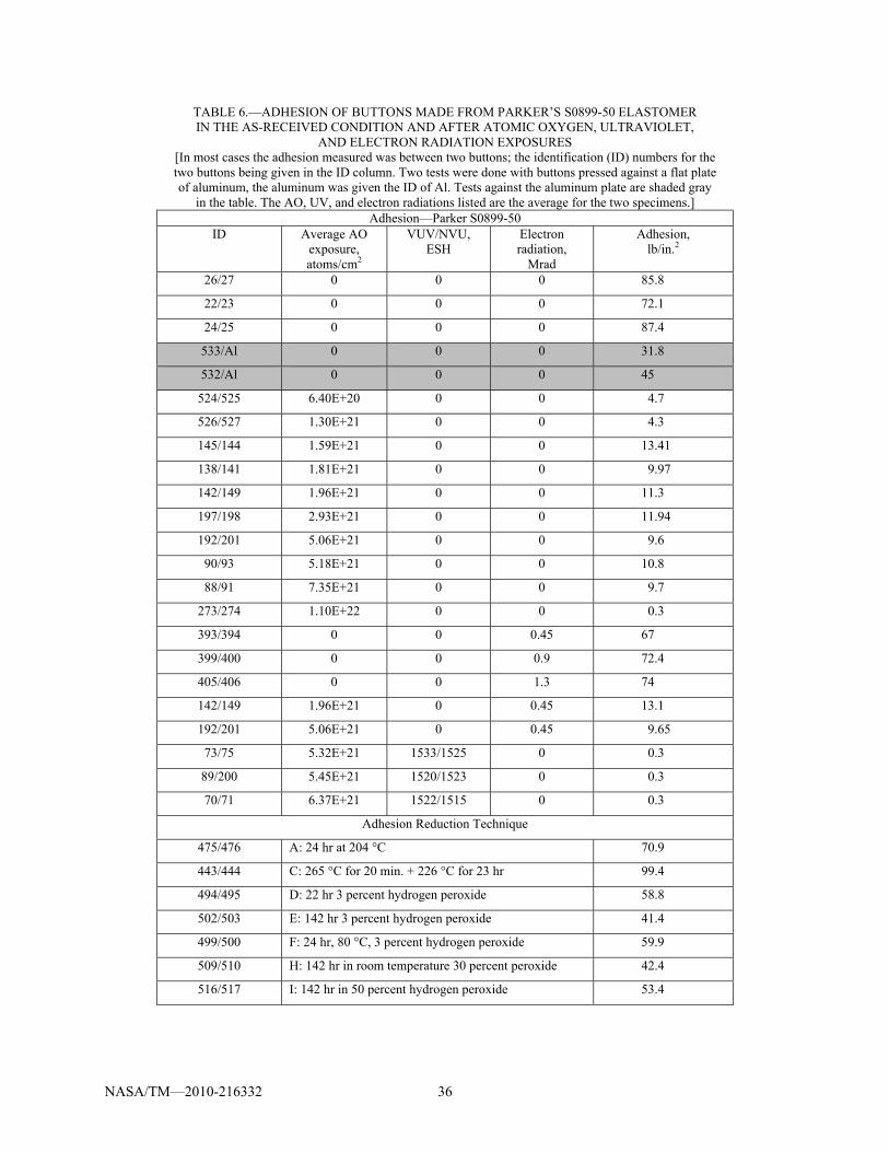
NASA/TM—2010-216332 36
TABLE 6.—ADHESION OF BUTTONS MADE FROM PARKER’S S0899-50 ELASTOMER IN THE AS-RECEIVED CONDITION AND AFTER ATOMIC OXYGEN, ULTRAVIOLET,
AND ELECTRON RADIATION EXPOSURES [In most cases the adhesion measured was between two buttons; the identification (ID) numbers for the two buttons being given in the ID column. Two tests were done with buttons pressed against a flat plate of aluminum, the aluminum was given the ID of Al. Tests against the aluminum plate are shaded gray
in the table. The AO, UV, and electron radiations listed are the average for the two specimens.] Adhesion—Parker S0899-50
ID Average AO exposure, atoms/cm2
VUV/NVU, ESH
Electron radiation,
Mrad
Adhesion, lb/in.2
26/27 0 0 0 85.8
22/23 0 0 0 72.1
24/25 0 0 0 87.4
533/Al 0 0 0 31.8
532/Al 0 0 0 45
524/525 6.40E+20 0 0 4.7
526/527 1.30E+21 0 0 4.3
145/144 1.59E+21 0 0 13.41
138/141 1.81E+21 0 0 9.97
142/149 1.96E+21 0 0 11.3
197/198 2.93E+21 0 0 11.94
192/201 5.06E+21 0 0 9.6
90/93 5.18E+21 0 0 10.8
88/91 7.35E+21 0 0 9.7
273/274 1.10E+22 0 0 0.3
393/394 0 0 0.45 67
399/400 0 0 0.9 72.4
405/406 0 0 1.3 74
142/149 1.96E+21 0 0.45 13.1
192/201 5.06E+21 0 0.45 9.65
73/75 5.32E+21 1533/1525 0 0.3
89/200 5.45E+21 1520/1523 0 0.3
70/71 6.37E+21 1522/1515 0 0.3
Adhesion Reduction Technique
475/476 A: 24 hr at 204 °C 70.9
443/444 C: 265 °C for 20 min. + 226 °C for 23 hr 99.4
494/495 D: 22 hr 3 percent hydrogen peroxide 58.8
502/503 E: 142 hr 3 percent hydrogen peroxide 41.4
499/500 F: 24 hr, 80 °C, 3 percent hydrogen peroxide 59.9
509/510 H: 142 hr in room temperature 30 percent peroxide 42.4
516/517 I: 142 hr in 50 percent hydrogen peroxide 53.4

NASA/TM—2010-216332 37
TABLE 7.—ADHESION OF BUTTONS MADE FROM PARKER’S S0383-70 ELASTOMER IN THE AS-RECEIVED CONDITION AND AFTER ATOMIC OXYGEN, ULTRAVIOLET,
AND ELECTRON RADIATION EXPOSURES [Adhesion measured was between two buttons; the identification (ID) numbers for the two buttons are given in the ID column. Adhesion tests against a flat plate of aluminum are given the ID of Al.
Tests between a button and an anodized aluminum plate include the ID AlAn. Tests against the bare the aluminum or anodized aluminum are shaded gray in the table. The AO, UV,
and electron radiations listed are the average for the two specimens.] Adhesion—Parker S0383-70
ID Average AO exposure, atoms/cm2
VUV/NUV, ESH
Electron radiation,
Mrad
Adhesion, lb/in.2
16/17 0 0 0 30.3
18/19 0 0 0 44.5
20/21 0 0 0 39.4
530/Al 0 0 0 4.25
531/Al 0 0 0 10.27
o-ring 535/Al 0 0 0 22.2
A12/A13 1.00E+18 0 0 12.6
B22/B23 3.00E+18 0 0 2.2
C32/C33 1.00E+19 0 0 1.6
748/749 7.00E+19 0 0 3.3
750/751 1.00E+20 0 0 1.5
520/521 6.40E+20 0 0 0.3
A12/Al 1.00E+18 0 0 4.9
B22/Al 3.00E+18 0 0 5.4
C32/Al 1.00E+19 0 0 2.8
753/Al 2.10E+19 0 0 3.34
754/Al 2.80E+19 0 0 4.5
784/Al 3.10E+19 0 0 1.76
789/Al 4.23E+19 0 0 2.34
791/Al 4.34E+19 0 0 2.06
785/Al 4.91E+19 0 0 1.07
787/Al 5.05E+19 0 0 2.26
769/Al 7.30E+19 0 0 0.3
764/Al 9.65E+19 0 0 0.61
767/Al 1.08E+20 0 0 0.3
758/Al 1.10E+20 0 0 0.67
520/Al 6.40E+20 0 0 0.3
768/AlAn 2.67E+19 0 0 1.5
782/AlAn 2.87E+19 0 0 1.3
779/AlAn 2.99E+19 0 0 0.63
761/AlAn 3.16E+19 0 0 2.9
781/AlAn 3.50E+19 0 0 4.13
762/AlAn 3.66E+19 0 0 2.11
756/AlAn 4.33E+19 0 0 3.63
777/AlAn 4.69E+19 0 0 2.68
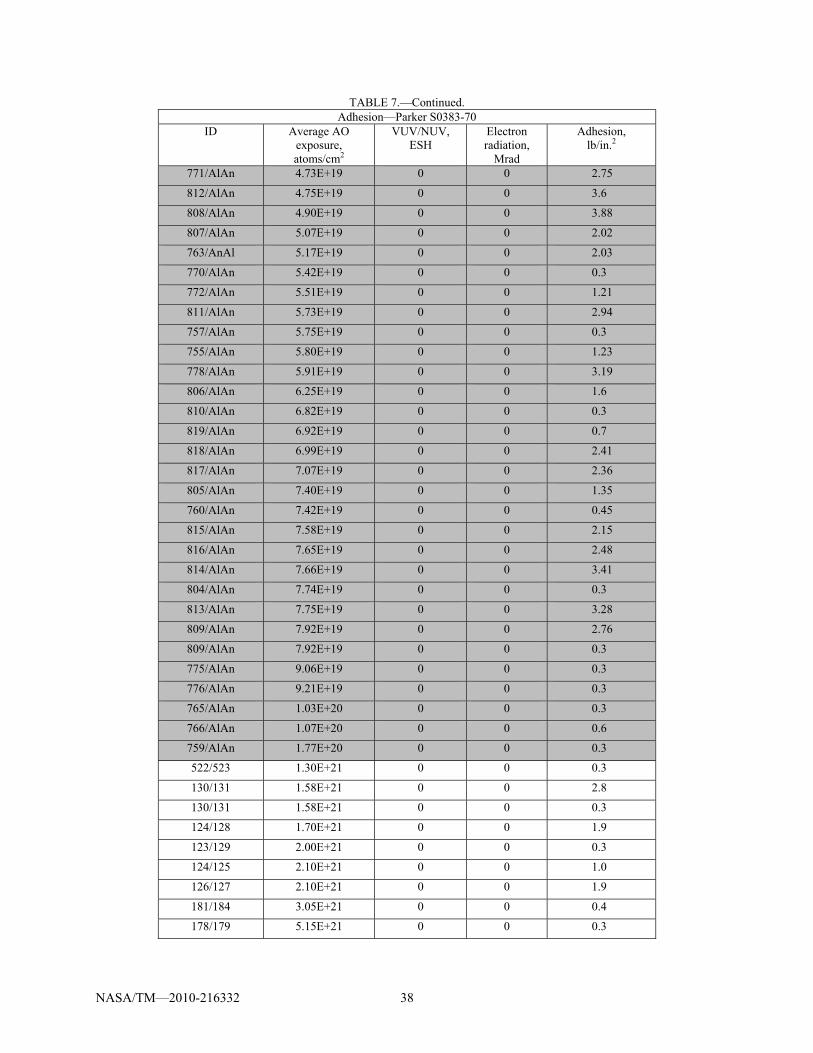
NASA/TM—2010-216332 38
TABLE 7.—Continued. Adhesion—Parker S0383-70
ID Average AO exposure, atoms/cm2
VUV/NUV, ESH
Electron radiation,
Mrad
Adhesion, lb/in.2
771/AlAn 4.73E+19 0 0 2.75
812/AlAn 4.75E+19 0 0 3.6
808/AlAn 4.90E+19 0 0 3.88
807/AlAn 5.07E+19 0 0 2.02
763/AnAl 5.17E+19 0 0 2.03
770/AlAn 5.42E+19 0 0 0.3
772/AlAn 5.51E+19 0 0 1.21
811/AlAn 5.73E+19 0 0 2.94
757/AlAn 5.75E+19 0 0 0.3
755/AlAn 5.80E+19 0 0 1.23
778/AlAn 5.91E+19 0 0 3.19
806/AlAn 6.25E+19 0 0 1.6
810/AlAn 6.82E+19 0 0 0.3
819/AlAn 6.92E+19 0 0 0.7
818/AlAn 6.99E+19 0 0 2.41
817/AlAn 7.07E+19 0 0 2.36
805/AlAn 7.40E+19 0 0 1.35
760/AlAn 7.42E+19 0 0 0.45
815/AlAn 7.58E+19 0 0 2.15
816/AlAn 7.65E+19 0 0 2.48
814/AlAn 7.66E+19 0 0 3.41
804/AlAn 7.74E+19 0 0 0.3
813/AlAn 7.75E+19 0 0 3.28
809/AlAn 7.92E+19 0 0 2.76
809/AlAn 7.92E+19 0 0 0.3
775/AlAn 9.06E+19 0 0 0.3
776/AlAn 9.21E+19 0 0 0.3
765/AlAn 1.03E+20 0 0 0.3
766/AlAn 1.07E+20 0 0 0.6
759/AlAn 1.77E+20 0 0 0.3
522/523 1.30E+21 0 0 0.3
130/131 1.58E+21 0 0 2.8
130/131 1.58E+21 0 0 0.3
124/128 1.70E+21 0 0 1.9
123/129 2.00E+21 0 0 0.3
124/125 2.10E+21 0 0 1.0
126/127 2.10E+21 0 0 1.9
181/184 3.05E+21 0 0 0.4
178/179 5.15E+21 0 0 0.3

NASA/TM—2010-216332 39
TABLE 7.—Concluded. Adhesion—Parker S0383-70
ID Average AO exposure, atoms/cm2
VUV/NUV, ESH
Electron radiation,
Mrad
Adhesion, lb/in.2
84/187 5.32E+21 0 0 0.3
65/69 5.78E+21 0 0 0.3
64/85 6.97E+21 0 0 0.3
68/87 7.62E+21 0 0 0.3
261/262 1.51E+22 0 0 0.3
375/376 0 0 0.45 44.2
381/382 0 0 0.9 36.2
387/388 0 0 1.3 24.6
124/128 1.70E+21 0 0.45 3.8
178/179 5.15E+21 0 0.45 0.3
65/69 5.78E+21 1582/1489 0 0.3
66/83 6.03E+21 1560/1503 0 0.3
67/82 6.52E+21 1533/1517 0 0.3
65/69 5.78E+21 1582/1489 0.45 0.3
Adhesion Reduction Technique
434/435 C: 265 °C for 20 min + 226 °C for 23 hr 57.5
507/508 H: 142 hr, 30 percent hydrogen peroxide 37.6

NASA/TM—2010-216332 40
TABLE 8.—ADHESION OF BUTTONS MADE FROM ESTERLINE’S ELA-SA-401 ELASTOMER IN THE AS-RECEIVED CONDITION AND AFTER ATOMIC OXYGEN, ULTRAVIOLET,
AND ELECTRON RADIATION EXPOSURES [Adhesion measured was between two buttons; the identification (ID) numbers for the two buttons are given
in the ID column. Adhesion tests against a flat plate of aluminum are given the ID of Al. Tests between buttons and an anodized aluminum plate include the ID AlAn. Tests against bare
aluminum or anodized aluminum are shaded gray in the table. The AO, UV, and electron radiations listed are the average for the two specimens.]
Adhesion—Esterline ELA-SA-401 ID Average AO
exposure, atoms/cm2
VUV/NUV, ESH
Electron radiation,
Mrad
Adhesion, lb/in.2
28/29 0 0 0 21.5
30/31 0 0 0 22.4
32/33 0 0 0 21.5
528/Al 0 0 0 4
529/Al 0 0 0 3.4
o-ring 534/Al 0 0 0 6.5
151/Al 2.00E+21 0 0 0.3
151/Al 2.00E+21 0 0 0.8
153/159 1.61E+21 0 0 0.3
158/160 1.74E+21 0 0 0.3
150/151 1.96E+21 0 0 0.3
206/213 3.10E+21 0 0 0.96
208/208 5.31E+21 0 0 0.3
94/96 7.20E+21 0 0 0.3
286/285 1.18E+22 0 0 0.3
413/414 0 0 0.45 23.6
419/420 0 0 0.9 25.5
423/424 0 0 1.3 22.75
150/151 1.96E+21 0 0.45 0.3
95/97 5.65E+21 1525/1495 0 0.3
76/98 5.83E+21 1547/1498 0 0.3
80/99 6.40E+21 1356/1354 80/0.45 0.3
76/80 6.10E+21 1565/1501 0.45 0.3

NASA/TM—2010-216332 41
TABLE 9.—COMPRESSION SET FOR PARKER’S S0899-50 #2-309 O-RINGS IN THE AS-RECEIVED CONDITION AND AFTER AO, UV, AND ELECTRON RADIATION
[O-rings from the same test were averaged together and are boxed together in the table (see bold outline). Special experiments designed to lower adhesion are included at the end.]
Compression set—Parker S0899-50 ID Average AO
exposure, atoms/cm2
VUV/NVU, ESH
Electron radiation,
Mrad
Compression set,percent
Average compression set,
percent
Standard deviation,
percent
4 0 0 0 8.36 7.7 0.60
5 0 0 0 7.78
6 0 0 0 6.89
171 2.96E+21 0 0 11.79 14.5 4.56
170 4.76E+21 0 0 20.9
61 5.19E+21 0 0 10.75
38 5.41E+21 0 0 10.66 8.9 2.94
37 6.22E+21 0 0 11.34
39 7.25E+21 0 0 4.79
232 1.10E+22 0 0 11.3 11.1 0.22
233 1.10E+22 0 0 10.86
236 2.33E+22 0 0 18.5 19.8 1.02
237 2.33E+22 0 0 19.76
238 2.33E+22 0 0 21.01
241 6.32E+22 0 0 29.6 26.7 2.37
242 6.32E+22 0 0 26.7
243 6.32E+22 0 0 23.8
341 0 0 0.45 2.85 3.5 3.13
342 0 0 0.45 0
344 0 0 0.45 7.6
347 0 0 0.9 9.2 12.1 2.26
348 0 0 0.9 14.7
349 0 0 0.9 12.5
353 0 0 1.3 2.53 2.7 1.01
354 0 0 1.3 1.53
355 0 0 1.3 4
53 5.42E+21 269/284 0 16.76 16.76 n/a
52 6.50E+21 294/358 0 18.8 18.8 n/a
54 6.70E+21 405/266 0 17 17 n/a
Adhesion Reduction Technique
471 A: 204 °C for 24 hr 11.4 10.1 3.16
472 A: 204 °C for 24 hr 13.1
473 A: 204 °C for 24 hr 5.7

NASA/TM—2010-216332 42
TABLE 9.—Concluded. Compression set—Parker S0899-50
ID Average AO exposure, atoms/cm2
VUV/NVU, ESH
Electron radiation, Mrad
Compression set,
percent 456 B: 225 °C for 24.5 hr 24.64 21.8 2.08
457 B: 225 °C for 24.5 hr 19.66
458 B: 225 °C for 24.5 hr 21.24
Adhesion Reduction Technique
491 D: 22 hr in 3 percent hydrogen peroxide 11.3 15.2 3.00
492 D: 22 hr in 3 percent hydrogen peroxide 15.6
493 D: 22 hr in 3 percent hydrogen peroxide 18.6

NASA/TM—2010-216332 43
TABLE 10.—COMPRESSION SET FOR PARKER’S S0383-70, #2-309 O-RINGS IN THE AS-RECEIVED CONDITION AND AFTER AO, UV, AND ELECTRON RADIATION
[O-rings from the same test were averaged together and are boxed together in the table (see bold outline). Special experiments designed to lower adhesion are included at the end.]
Compression set—Parker S0383-70 ID Average AO
exposure, atoms/cm2
VUV/NVU, ESH
Electron radiation,
Mrad
Compression set, percent
Average compression set,
percent
Standard deviation,
percent
1 0 0 0 10.09 8.9 1.38
2 0 0 0 6.99
3 0 0 0 9.7
100 2.52E+21 0 0 13.7 14.6 1.13
167 2.84E+21 0 0 16.2
51 4.90E+21 0 0 13.9
34 6.02E+21 0 0 15.24 15.0 2.92
35 6.49E+21 0 0 18.47
36 7.64E+21 0 0 11.32
216 1.51E+22 0 0 14.17 17.1 2.28
217 1.51E+22 0 0 19.75
218 1.51E+22 0 0 17.3
221 3.02E+22 0 0 24.2 21.6 1.88
222 3.02E+22 0 0 20.44
223 3.02E+22 0 0 20.01
226 6.33E+22 0 0 24.7 25.1 0.45
227 6.33E+22 0 0 24.8
228 6.33E+22 0 0 25.7
323 0 0 0.45 6.35 9.7 2.64
324 0 0 0.45 12.8
325 0 0 0.45 10.03
329 0 0 0.9 10.6 12.8 1.55
330 0 0 0.9 13.6
331 0 0 0.9 14.1
335 0 0 1.3 7.04 6.1 0.71
336 0 0 1.3 5.81
337 0 0 1.3 5.36
59 5.60E+21 452/250 0 16.9 16.9 n/a
58 6.02E+21 177/284 0 20.32 20.32 n/a
50 6.55E+21 295/358 0 15.77 15.77 n/a
Adhesion Reduction Technique 465 A: 204 °C for 24 hr 16.6 14.8 1.99
466 A: 204 °C for 24 hr 15.7
467 A: 204 °C for 24 hr 12

NASA/TM—2010-216332 44
TABLE 10.—Concluded. Compression set—Parker S0383-70
ID Average AO exposure, atoms/cm2
VUV/NVU, ESH
Electron radiation,
Mrad
Compression set, percent
Average compression set,
percent
Standard deviation,
percent
447 B: 225 °C for 24.5 hr
B: 225 °C for 24.5 hr
B: 225 °C for 24.5 hr
17.75 18.6 1.53
448 20.74
449 17.29

NASA/TM—2010-216332 45
TABLE 11.—COMPRESSION SET FOR ESTERLINE’S ELA-SA-401 ELASTOMER SIZE #2-309 O-RINGS IN THE AS-RECEIVED CONDITION AND AFTER AO, UV, AND ELECTRON RADIATION
[O-rings from the same test were averaged combined and are boxed together in the table.] Compression set—Esterline ELA-SA-401
ID Average AO exposure, atoms/cm2
VUV/NUV, ESH
Electron radiation,
Mrad
Compression set, percent
Average compression set,
percent
Standard deviation,
percent 7 0 0 0 19.23 19.3 2.52
8 0 0 0 16.3
9 0 0 0 22.46
40 5.89E+21 0 0 15.76 16.1 0.35
41 6.94E+21 0 0 15.93
42 6.55E+21 0 0 16.57
246 1.00E+22 0 0 25.9 24.6 0.90
247 1.00E+22 0 0 24.2
278 1.00E+22 0 0 23.84
251 3.20E+22 0 0 30.6 37.2 6.53
252 3.20E+22 0 0 46.1
253 3.20E+22 0 0 34.9
359 0 0 0.45 6.98 12.6 4.19
360 0 0 0.45 13.96
361 0 0 0.45 16.99
365 0 0 0.9 16.96 20.0 2.50
366 0 0 0.9 23.09
367 0 0 0.9 20
371 0 0 1.3 5.05 12.0 5.16
372 0 0 1.3 13.6
373 0 0 1.3 17.4
56 5.63E+21 177/284 0 23.7 23.7 n/a
62 5.64E+21 428/290 0 25 25 n/a
57 5.77E+21 270/284 0 35.75 35.75 n/a

REPORT DOCUMENTATION PAGE Form Approved
OMB No. 0704-0188 The public reporting burden for this collection of information is estimated to average 1 hour per response, including the time for reviewing instructions, searching existing data sources, gathering and maintaining the data needed, and completing and reviewing the collection of information. Send comments regarding this burden estimate or any other aspect of this collection of information, including suggestions for reducing this burden, to Department of Defense, Washington Headquarters Services, Directorate for Information Operations and Reports (0704-0188), 1215 Jefferson Davis Highway, Suite 1204, Arlington, VA 22202-4302. Respondents should be aware that notwithstanding any other provision of law, no person shall be subject to any penalty for failing to comply with a collection of information if it does not display a currently valid OMB control number. PLEASE DO NOT RETURN YOUR FORM TO THE ABOVE ADDRESS.
1. REPORT DATE (DD-MM-YYYY) 01-07-2010
2. REPORT TYPE Technical Memorandum
3. DATES COVERED (From - To)
4. TITLE AND SUBTITLE Space Environment Effects on Silicone Seal Materials
5a. CONTRACT NUMBER
5b. GRANT NUMBER
5c. PROGRAM ELEMENT NUMBER
6. AUTHOR(S) de Groh, Henry, C., III; Daniels, Christopher, C.; Dever, Joyce, A.; Miller, Sharon, K.; Waters, Deborah, L.; Finkbeiner, Joshua, R.; Dunlap, Patrick, H., Jr.; Steinetz, Bruce, M.
5d. PROJECT NUMBER
5e. TASK NUMBER
5f. WORK UNIT NUMBER WBS 644423.06.31.04.01.03.22
7. PERFORMING ORGANIZATION NAME(S) AND ADDRESS(ES) National Aeronautics and Space Administration John H. Glenn Research Center at Lewis Field Cleveland, Ohio 44135-3191
8. PERFORMING ORGANIZATION REPORT NUMBER E-17267
9. SPONSORING/MONITORING AGENCY NAME(S) AND ADDRESS(ES) National Aeronautics and Space Administration Washington, DC 20546-0001
10. SPONSORING/MONITOR'S ACRONYM(S) NASA
11. SPONSORING/MONITORING REPORT NUMBER NASA/TM-2010-216332
12. DISTRIBUTION/AVAILABILITY STATEMENT Unclassified-Unlimited Subject Categories: 18, 27, and 38 Available electronically at http://gltrs.grc.nasa.gov This publication is available from the NASA Center for AeroSpace Information, 443-757-5802
13. SUPPLEMENTARY NOTES
14. ABSTRACT A docking system is being developed by the NASA to support future space missions. It is expected to use redundant elastomer seals to help contain cabin air during dockings between two spacecraft. The sealing surfaces are exposed to the space environment when vehicles are not docked. In space, the seals will be exposed to temperatures between 125 to -75 °C, vacuum, atomic oxygen, particle and ultraviolet radiation, and micrometeoroid and orbital debris (MMOD). Silicone rubber is the only class of space flight-qualified elastomeric seal material that functions across the expected temperature range. NASA Glenn has tested three silicone elastomers for such seal applications: two provided by Parker (S0899-50 and S0383-70) and one from Esterline (ELA-SA-401). The effects of atomic oxygen (AO), UV and electron particle radiation, and vacuum on the properties of these three elastomers were examined. Critical seal properties such as leakage, adhesion, and compression set were measured before and after simulated space exposures. The S0899-50 silicone was determined to be inadequate for extended space seal applications due to high adhesion and intolerance to UV, but both S0383-70 and ELA-SA-401 seals were adequate. 15. SUBJECT TERMS Elastomers; Adhesion; Outgassing; Ultraviolet radiation; Electron radiation; Low Earth orbits; Leakage; Silicone rubber
16. SECURITY CLASSIFICATION OF: 17. LIMITATION OF ABSTRACT UU
18. NUMBER OF PAGES
51
19a. NAME OF RESPONSIBLE PERSON STI Help Desk (email:[email protected])
a. REPORT U
b. ABSTRACT U
c. THIS PAGE U
19b. TELEPHONE NUMBER (include area code) 443-757-5802
Standard Form 298 (Rev. 8-98)Prescribed by ANSI Std. Z39-18

