space mountain
TRANSCRIPT
8/19/2019 Space Mountain
http://slidepdf.com/reader/full/space-mountain 1/18
1
Arfa, Belleculée, Op latka, J .-M. Teissier, Roland Verreet
A. Arfa, A. Belleculée Euro Disney SCA, ParisG. Oplatka ETH Zürich J .-M. Teissier DEP Engineering, FranceRoland Verreet Ingenieurbüro für Fördertechnik., Aachen Germany
Space Mountain at Euro Disney:A 120 million dollar wire rope test machine
Summary
The service conditions of the rope from the Space Mountain rope-drive at Euro Disneyare discussed. These ropes are discarded after about 3 months and 120,000 catapultoperations, a figure which was predicted in the design phase using modern wire ropeendurance prediction methods. Every rope section is subjected to the same conditions
every 36 seconds, the mode of operation never changes. Some rope sections are onlysubjected to tension- tension fatigue, others to tension- tension and bending fatigue.Daily visual rope inspections and magnetic rope testing at regular intervals, as well asdestructive rope tests after discard, provide an enormous amount of “real life“ datawhich has been compared with the theoretical predictions. The paper also presents amethod of determining the most favourable length of rope to slip and cut and discussthe results of this procedure.
1. What is Space Mountain?
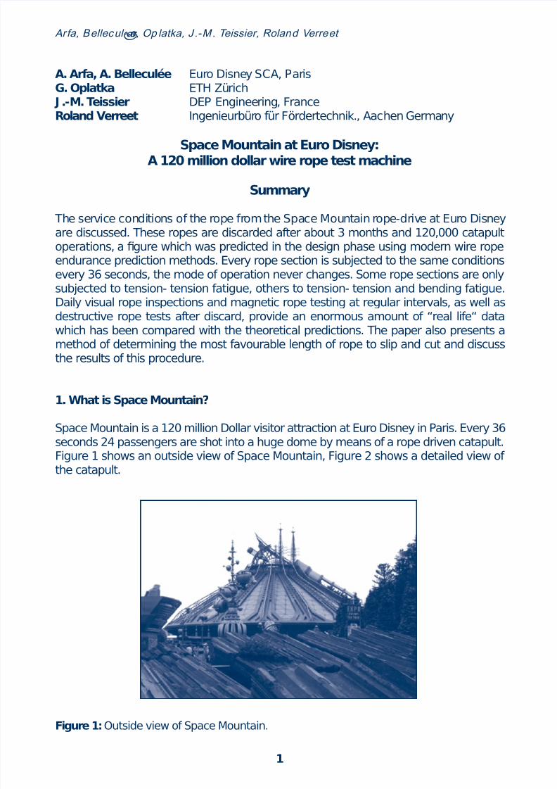
Space Mountain is a 120 million Dollar visitor attraction at Euro Disney in Paris. Every 36seconds 24 passengers are shot into a huge dome by means of a rope driven catapult.Figure 1 shows an outside view of Space Mountain, Figure 2 shows a detailed view ofthe catapult.
Figure 1: Outside view of Space Mountain.

8/19/2019 Space Mountain
http://slidepdf.com/reader/full/space-mountain 2/18
2
Arfa, Belleculée, Op latka, J .-M. Teissier, Roland Verreet
When the passengers are seated and secured, when the glasses have been taken offand the false teeth are stored in the pocket, the train moves down to the bottom of thecanon slope by means of gravity. Then the catapult pusher loads the canon: It movesthe train into the departure position in the lower section of the track which is 50m longand inclined by 32 degrees (Figure 3).
Figure 2: Outside view of the catapult.
Figure 3: Inside view of catapult.

8/19/2019 Space Mountain
http://slidepdf.com/reader/full/space-mountain 3/18
3
Arfa, Belleculée, Op latka, J .-M. Teissier, Roland Verreet
After a short waiting time increasing the tension of the passengers the canon is fired:the background music is interrupted by a loud bang, smoke comes out the canon, andthe train rapidly takes off. Under the acceleration of 1,3 g the passengers are pressedinto their seats and the train reaches a speed of more than 50km/h in less than 2 se-conds.
Shortly before the summit of the slope is reached, the pusher de-cele-rates. The trainenters the dome, subjecting the passen-gers to a short moment of weightless condition.After another 90 seconds of breathtaking roller coaster trip the passengers will againarrive at their point of departure (Figure 4). Space Mountain was opened in May 1995.At the time of writing this article (April 1997), already more than 17 million passengershave been shot into space by the rope driven catapult.
Figure 4: Arrival of the train.
2. Why do wire rope researchers love Space Mountain?
Space Mountain is a very interesting source for wire rope fatigue data. It represents oneof the very rare wire rope applications where the operating conditions are not only verysevere but known in every detail. In addition, conditions are constantly being monitoredthroughout the whole wire rope life.
Every rope section is subjected to the same conditions every 36 seconds; the modeof operation never changes. At wire rope discard, every section will have undergonethe same stress history 120,000 times. At the time of writing this article, 8 ropes have

8/19/2019 Space Mountain
http://slidepdf.com/reader/full/space-mountain 4/18
4
Arfa, Belleculée, Op latka, J .-M. Teissier, Roland Verreet
been discarded and analyzed, representing the fatigue data of about 1 million catapultshots.
3. A short technical description of the catapult system
The catapult reeving is a pretensioned ‚closed loop‘ system. It consists of
• a grooved drum of 1000mm diameter• a pushing device attached to the rope, called the ‚pusher‘,• a headstock sheave of 1200mm diameter• a midspan supporting sheave of 400mm; and• a 185m long steel wire rope (Figure 5).
Figure 5: Schematic drawing of the catapult.
32tailstockdrum
pusher
rope
headstocksheave
midspansheave
3.1 The rope
The steel wire rope type Casar Turboplast has a nominal diameter of 36mm a wire gradeof 1770 N/mm2 and consists of an independent steel wire rope core, a plastic layer andeight compacted outer strands (Figure 6).
The rope travels from the drum through the pusher, where it is held by friction, to theheadstock sheave where it is deflected by 180°. It travels back to the drum via the mid-span supporting sheave.
The rope ends are attached to the drum in correspondingly and over-win-ding and un-
derwinding. As the drum rotates, one rope end is wound onto the drum and the otherend is payed off. As a consequence, the rope length stored on the drum always remainsthe same: it corresponds to the length of the pusher stroke plus the required dead

8/19/2019 Space Mountain
http://slidepdf.com/reader/full/space-mountain 5/18
5
Arfa, Belleculée, Op latka, J .-M. Teissier, Roland Verreet
wraps. This con-fi-gu-ra-tion allowed the design of a very short drum with only onewrap empty, resulting in very small fleet angles for the wire rope.
Figure 6: The rope: Casar Turboplast.
3.2 The trailstock drum
The trailstock drum is made out of forged alloy steel. After tempering, an additional heattreatment has been applied in order to increase the groove hardness. The procedurehas proven extremely successful: during each operation, every section of the groove
accommodates the rope once in the launching phase and then once in the reel-backphase. In April 1997, after about one million catapult operations, every groove sec-tion has wound the rope on and off about 2 million times. Still almost no wear can bemeasured in the grooves. Disney has a spare drum in stock. It looks as if it will be therefor a while.
Maybe the improved contact conditions of the compacted outer strands of the ropehave helped the situation. But still the result is astonishing.
3.3 The headstock sheave
The headstock sheave is made out of the same material and has been subjected tothe same treatment as the drum. The sheave moves on its own track to allow for ropetensioning by means of a screw actuated tensioning systems.
Normally, in similar arrangements, counterweight systems would be used to keep thereelback rope under constant tension. Because of the extreme accelerations of thecatapult, however, the reaction time of any such systems would not have been satisfac-tory. Therefore it was decided to pretension the ‘closed loop’ system to a constant levelby means of screw actuators acting on the headstock sheave. The level of pretension is
constantly being monitored. Whenever a reduction is measured, the headstock sheaveis unlocked and moved until the required level of pretension is re-established. Then thesheave is locked again for the launch phase.

8/19/2019 Space Mountain
http://slidepdf.com/reader/full/space-mountain 6/18
6
Arfa, Belleculée, Op latka, J .-M. Teissier, Roland Verreet
3.4 The pusher
The pusher is a carriage running on its own track about am below the train tracks. Itspurpose is to push the train in the loading and launching phase by means of a fin.
The pusher isfixed on the rope by means of two sets of aluminum friction sheaves. Thediameter of the sheaves is about 20 times the diameter of the rope (Fig. 7). At the ent-rance and at the exit of the pusher, the wire rope is deflected by saddles with a radiusof about 80 times the rope diameter.
Figure 7: The pusher.
During the installation procedure, the friction sheaves in the pusher are free to rotate.
Therefore the rope can simply be pulled through the sheave system. After the rope isinstalled, the position of the pusher is adjusted and the pretension is applied. As thesheaves in the pusher are still able to rotate, the pretension forces can also be transmit-ted to the rope length stored in the pusher. In this condition, the rotation of the frictionsheave sets in the pusher is blocked, converting the system into a double bollard.In order to minimize the fleet angles between the sheaves (which would twist the ropeduring installation), one of the sets of sheaves is inclined relative to the other. The num-ber of friction sheaves was calculated so that the rope would not move in any part ofthe pusher under the differences in line pull occurring during operation. In case the ropemight still show some movement, a fixing point for a clamp had been included at theend of each saddle. Experience has shown, however, that these clamps are not neces-sary.
By attaching the pusher the rope by means of the double-bollard arrangement, onecontinuous rope length could be used instead of using two ropes. This not only allowedfor a much easier rope installation and an easy adjustment of the pusher position, it alsoavoided the use of two rope end connections which could have been susceptible totension- tension fatigue. In addition, the arrangement allows the use of a magnetic ropetest for the whole rope length. Furthermore, if ever the pusher gets stuck, the rope canslip over the friction sheaves instead of destroying the whole power train.
The most important argument, however, was that this arrangement makes it possibleto move the pusher along the rope after a certain number of catapult operations. This

8/19/2019 Space Mountain
http://slidepdf.com/reader/full/space-mountain 7/18
7
Arfa, Belleculée, Op latka, J .-M. Teissier, Roland Verreet
shifts the zones of maximum stresses along the rope length, thereby increasing the wirerope service life.
4. The rope stresses
At every catapult operation, different zones of the steel wire rope are subjected to diffe-rent stresses. Some areas are subjected to tension-tension stresses only, while othersin addition are subjected to bending on the headstock sheave or the drum. Sever diffe-rent zones A to G can be distinguished (Fig. 8). Figure 9 lists the loading modes in thedifferent zones.
Figure 08: Zones A through G.
Figure 09: Stress modes in different rope zones.
B
A
D
C
E
32
F
G
Zone
A
B
C
D
E
F
G
Length[m]
41
2
12
6
39
9
41
Tension-Tension
•
•
•
•
•
•
•
Bending
• ( on drum)
–
–
–
• • (on sheave)
–
• (on drum)

8/19/2019 Space Mountain
http://slidepdf.com/reader/full/space-mountain 8/18
8
Arfa, Belleculée, Op latka, J .-M. Teissier, Roland Verreet
Figure 10 shows the line pull of the traction rope (zones D to G) and of the reel backrope (zones A and B) as well as the carriage velocity as a function of time. During theacceleration phase the forces in the traction rope increase dramatically, while the forcesin the reelback rope are reduced.
As the line pull changes dramatically during one catapult operation, different rope sec-tions will be Benton the tailstock winch or the headstock sheave under different levelsof the line pull. Figure 11 shows the line pull when bending, as a function of the ropelength. Two rope lengths of about 20m (zones B,C and D) and of 9m (zone F) are notsubjected to bending.
Figure 10: Rope tensions and train velocity over time.
180.000
160.000
140.000
120.000
100.000
80.000
60.000
40.000
20.000
0
-20.000
-40.000
0 2 4 6 8 10 12 14 16 18 20
30
20
10
0
-10
Attach
V
e l o c i t y [ m / s ]
R o p e
T e n s i o n [ N ]
Loading
Pusher velocity
Reelback rope tension
Traction rope tension
Launch Reelback
Time [s]
Figure 11: Line pull while bending.
180.000
160.000
140.000
120.000
100.000
80.000
60.000
40.000
20.000
0 0 5
1 0
1 5
2 0
2 5
3 0
3 5
4 0
4 5
5 0
5 5
6 0
6 5
7 0
7 5
8 0
8 5
9 0
9 5
1 0 0
1 0 5
1 1 0
1 1 5
1 2 0
1 2 5
1 3 0
1 3 5
1 4 0
1 4 5
1 5 0
R o p e t e n s i o n w h e n b e n d i n g [ N ]
Rope length [m]
Reel back rope
Tailstock drum
Traction rope
Headstock sheave
Traction rope
Tailstock drum
Reel backLaunch

8/19/2019 Space Mountain
http://slidepdf.com/reader/full/space-mountain 9/18
9
Arfa, Belleculée, Op latka, J .-M. Teissier, Roland Verreet
The level of pretension was based on three main factors. First of all the catapult had tofit into the dimensions set by the building. This only allows for a very limited wire ropesag and therefore requires the maximum possible level of pretension.
Another argument for a high pretension was the fact that the pusher is attached to the
rope by friction only. Therefore the system would react very sensitively to variations ofthe rope tension. Especially throughout the launch phase a minimum level of tensionhad to be guaranteed in the reelback rope to avoid slippage. On the other hand, withincreasing level of pretension the rope would be wound on and off the drum and travelover the headstock sheave under much higher tension. Therefore with increasing levelof pretension an increasing reduction in service life could be expected.
Therefore wire rope service life prediction methods had to be used to find the maximumpossible pretension that would give a satisfactory service life.
5. The application of wire rope service life prediction methods in the design phase
For the bending fatigue prediction a program based on the Feyrer (1993) formula wasused. The program would not only predict the number of cycles to discard and break forthe given set of data, but would also illustrate the influence of the different parameterson the result.
As an example, Figure 12 to 14 show the service life to discard (lower curve) and tobreak (upper Curve) depending on the nominal rope diameter (Figure 12), on the sheavediameter (Figure 13) and on the line pull (Figure 14).
Figure 12 shows a pronounced maximum for the service life at a nominal rope diameterof 40mm. Ropes with smaller diameters have a lower service life because of the speci-fically higher line pull, ropes with bigger diameters have a lower service life because ofthe relatively higher bending stresses.
The tension-tension behavior of the rope was determined by a large number of testsusing the 240t dynamic rope tester at Casar.
The influence of the combined action of bending and tension-tension fatigue was cal-culated using the Palmgreen- Miner rule.
The results of the service life predictions influenced the design and the dimensions ofthe rope that in turn influenced the design of all other components of the catapult.
5.1. The wire rope section
The wire rope for the catapult had to fulfill a certain number of criteria: it had to have avery high breaking strength, goods abrasion resistance, good structural stability and ahigh bending and tension-tension fatigue resistance.
Charts such as Figure 10 were sent to a many different rope manufacturers. Most ofthem declined even to make a proposal.

8/19/2019 Space Mountain
http://slidepdf.com/reader/full/space-mountain 10/18
10
Arfa, Belleculée, Op latka, J .-M. Teissier, Roland Verreet
18 20 22 24 26 28 30 32 34 36 38 40 42 44 46 48 50 5452
750.000
700.000
650.000
600.000
550.000500.000
450.000
400.000
350.000
300.000
250.000
200.000
150.000
100.000
50.000
0
N u m b e r o f C y c l e s [ - ]
Nominal Rope Diameter [ mm ]
Number of cycles dependingon the nominal rope diameter
Disney ProjectSpace Mountain
500 600 700 800 900 1000 1100 1200 1300 1400 1500
2.000.000
0
N u m b e r o
f C y c l e s [ - ]
Sheave Diameter [ mm ]
Number of cycles dependingon the sheave diameter
Disney ProjectSpace Mountain
1.900.000
1.800.000
1.700.000
1.600.000
1.500.000
1.400.000
1.300.000
1.200.000
1.100.000
1.000.000
900.000
800.000
700.000
600.000
500.000
400.000
300.000
200.000
100.000
Figure 12: Number of cycles depending on the nominal rope diameter.
Figure 13: Number of cycles depending on the sheave diameter.

8/19/2019 Space Mountain
http://slidepdf.com/reader/full/space-mountain 11/18
11
Arfa, Belleculée, Op latka, J .-M. Teissier, Roland Verreet
Figure 14: Number of cycles depending on the line pull.
40.000 50.000 60.000 70.000 80.000 90.000 100.000 110.000 120.000
2.000.000
0
N u m b e r o f C y c l e s [ - ]
Line Pull [ N ]
Number of cycles dependingon the line pull
Disney Project
Space Mountain
1.900.000
1.800.000
1.700.000
1.600.000
1.500.000
1.400.000
1.300.000
1.200.000
1.100.000
1.000.000
900.000
800.000
700.000
600.000
500.000
400.000
300.000
200.000
100.000
Finally, several ropes were given closer consideration. The bending fatigue behavior
could be predicted by the program, whereas very little was known on the tension-ten-sion fatigue behavior of the ropes. Therefore a large number of tension-tension fatiguetests have been carried out with different rope designs in diameters between 36 and42 mm.
Both the bending fatigue calculations and the tension-tension test results showed thata rope Casar Turboplast would be most suitable choice.
5.2 The mode of calculation
Starting from a relatively low rope diameter for ease of installation, thefinal rope diame-ter, the level of pretension, and the sheave and drum dimensions have been calculatediteratively for different rope zones as shown in Figure 15.
For the final layout and the final operating conditions, a total number of 110,000 cata-pult cycles of discard has been predicted.
6 Wire rope inspection
The wire rope of Space Mountain catapult is being regularly inspected by visual inspec-tion and magnetic testing.

8/19/2019 Space Mountain
http://slidepdf.com/reader/full/space-mountain 12/18
12
Arfa, Belleculée, Op latka, J .-M. Teissier, Roland Verreet
6.1 Visual Inspection on site
During thefirst week after the installation, the rope is subjected to a daily visual inspec-tion. This is to detect any possible problems created by the new rope or the installationprocess. The intervals between the inspections are increased to one week. After thefirst wire breaks have been detected either by visual or magnetic inspection, the inspec-tion intervals are again reduced.
6.2 Magnetic testing of site
Immediately after the installation a magnetic rope inspection is carried out in order toprovide a reference diagram. The next magnetic tests are carried out after about 20,000and 40,000 catapult cycles. After the first wire breaks have been detected, the inspec-tion intervals are reduced to about 8,000 catapult cycles. Immediately before discar-ding the rope , a final magnetic test is performed on the catapult. During every test, thewire breaks along the rope length are recorded on a chart.
About twelve meters of rope are constantly stored in the pusher and are therefore notaccessible for magic testing. As there was concern that the rope sections entering andleaving the pusher could be subject to particular tension-tension fatigue, for the firstwire ropes the aluminum friction sheaves of the pusher have been unlocked and thepusher has been shifted. Then the rope length normally stored in the pusher was also
Figure 15: Flow chart showing the calculation procedure.
Start with rope diameter
32 mm
Proposal for new
(optimum) rope diameter
Calculation of pretension
and load changes
Calculation of
sheave diameter and
drum diameter
Calculation of
bending fatigue
Tension-tension tests +
extrapolation of results
Application of
Palmgren- Miner rule
Service life prediction

8/19/2019 Space Mountain
http://slidepdf.com/reader/full/space-mountain 13/18
13
Arfa, Belleculée, Op latka, J .-M. Teissier, Roland Verreet
tested. During these procedures, not a single broken wire has ever been found in thepusher length, an observation that was always confirmed later both by the manual andthe magnetic inspection of the total discarded rope length in the workshop. Thereforethis time-consuming procedure was abandoned.
The numbers of broken wires found during the magnetic testing are entered into aspreadsheet and analyzed.
Figure 16: Typical view of the rope after about 80.000 catapult cycles.
6.3 Magnetic testing of the discarded rope
The eight ropes discarded so far have been shipped back to the Casar workshop forfurther tests. First the wire ropes have been subjected to a magnetic test using thesame tester as at Euro Disney. So far the charts obtained the workshop always showfew more wire breaks than the charts obtained immediately before discarding the rope. This could be explained by additional damage to the rope during removal and by thefact that the test performed on the catapult is always carried out under a pretension of125,000N, whereas in the workshop the rope is always tested without tension.
6.4 Destructive testing of the discarded rope
After the magnetic test, the seven different rope zones defined in Figure 8 are marked. Then samples are taken from these different zones for destructive tests. One length isalways subjected to a pulltest to destruction, while the adjacent length is dismantledin order to detect internal wire breaks and to examine the condition of the plastic layer.

8/19/2019 Space Mountain
http://slidepdf.com/reader/full/space-mountain 14/18
14
Arfa, Belleculée, Op latka, J .-M. Teissier, Roland Verreet
The first wire ropes were discarded at about 100,000 catapult cycles when the discardcriteria of DIN 15020, part 2 had been reached in the rope zones spooling on and off thedrum. In a pull test to destruction, the worst sections of these ropes achieved an ave-rage 93% of the breaking strength of the new rope. Only very few internal wire breakswere found, and the plastic layer of the rope was still in very good condition. Therefore
it was decided to allow for a for a greater number of wire breaks for the following ropes. These have been operated with successively increasing numbers of catapult cycles, upto a figure of 130,000 catapult cycles.
As could be expected, the number of visible broken wires showed a disproportiona-te increase with the number of catapult cycles. It was also no surprise that the breaktests of the discarded ropes showed a continuous decline in remaining rope breakingstrength with increasing number of catapult cycles(Figure 17).
Figure 17: Remaining breaking strength of the rope as a function of the number of catapult cycles.
80.000 90.000 100.000 110.000 120.000 130.000
100
60
R e m a i n i n g
r o p e b r e a k i n g s t r e n g t h
[ % ]
Number of catapult cycles [ - ]
98
96
94
92
90
88
86
84
82
80
78
76
7472
70
68
66
64
62
7 Service life analysis: Comparison of predictions and real life fatigue data
For the service life predictions, zones A, E and G, which are the only zones subjected toboth bending and tension-tension loading, have been analyzed. Spooling on and off thedrum, zones A and G undergo one bending cycle during every catapult cycle. At the sametime, zone E undergoes two bending cycles on the headstock sheave which has a 20%bigger diameter than the drum. The calculation showed that zone E was more critical.Figure 18 shows a typical chart of the broken wire density on 30x d after 100,000 cata-
pult cycles as a function of position along the rope length. The rope zones which travelover the headstock sheave and on and off the drum during launch can clearly be identi-fied. In zone E, the discard number of 35 wires on 30xdhas not yet been reached.

8/19/2019 Space Mountain
http://slidepdf.com/reader/full/space-mountain 15/18
15
Arfa, Belleculée, Op latka, J .-M. Teissier, Roland Verreet
A pronounced peak is visible on the traction rope at about 147m. This rope sectionspools onto the drum when the pusher attaches to the train. The shockload during at-tachment had not been foreseen in the design stage. In the meantime measures havebeen taken to eliminate this shock..
7.1 Zones B,C and F (tension-tension only)
It is remarkable that in spite of the high dynamic forces wire breaks can only be found inthose areas which are subjected to bending. All rope zones which experience tension-tension only (zones B, D, F) and the length stored in the pusher (zone C) do not showa single wire break at discard. So the influence of tension-tension only is obviously nottoo harmful.
7.2 Zone E (traveling over the headstock sheave)
The service life under the combined influence of tension-tension and bending stresseshas been predicted to 110,000 catapult cycles for zone E.
Zone E behaves just as predicted. The discard number of wire breaks is reached atabout 110,000 catapult cycles.
7.3 Zones A and G (spooling on and off the drum)
In zones A and G, we can distinguish between zones spooling on and off the drum underrelatively constant line pull, and zones which at the same time undergo a sharp changein line pull. The zones with the relatively constant line pull behave just as predicted.
Figure 18: Broken wire density on 30 x d as a function of the rope length.
50
40
30
20
10
0 0 5
1 0
1 5
2 0
2 5
3 0
3 5
4 0
4 5
5 0
5 5
6 0
6 5
7 0
7 5
8 0
8 5
9 0
9 5
1 0 0
1 0 5
1 1 0
1 1 5
1 2 0
1 2 5
1 3 0
1 3 5
1 4 0
1 4 5
1 5 0
B r o k e n w i r e s d e n s i t y [ - ]
Rope length [m]
Traction ropePusherReelback rope
A C
B D
E F G

8/19/2019 Space Mountain
http://slidepdf.com/reader/full/space-mountain 16/18
16
Arfa, Belleculée, Op latka, J .-M. Teissier, Roland Verreet
In zones with a combination of bending and load changes, however, the density of wirebreaks increases at a faster rate towards the end of the rope life.
In thefirst half of the rope life, the wire density in zones A and G is lower than in zone E, just as predicted. In the second half of the rope life, however, the wire breaks develop
at a faster rate in zones A and G, so that finally the discard criteria are reached in thesezones which spool on and off the drum after about 100,000 catapult cycles. It was onlyafter we had decided to keep the ropes in operation even after the discard criteria werereached in zones A and G that we found that the discard criteria were reached in zoneE at about 110,000 cycles, as predicted.
Other than on the headstock sheave, the combined influence of tension-tension andbending stresses on the drum is much more pronounced than the application of thePalmgreen- Miner rule would suggest.A possible explanation could be the fact that the rope is lengthened during every loadchange. For rope section lying on the sheave, a length adjustment is possible on bothsides, and a relative motion between the headstock sheave and rope is possible. Thisexplanation is supported by the observation that after every catapult cycle, the sheavemust be set back by 20mm.
On the drum, however, a length adjustment is only possible towards one side.
8 Increasing the service life by shifting the rope
On lifting with a continuously changing mode of operation, with every lift different ropesections are subjected to tension-.tension or bending fatigue. Therefore these machi-nes normally show a random distribution of wire breaks along the rope length.
On machines with repetitive motions, like automatic stackers, on the other hand,, withevery lift the same rope sections are subjected to the same stresses. Therefore thesemachines tend to show concentrations of wire breaks in a few areas of high fatigue.
The catapult was designed to repeat exactly the same operation 100,000 times with thesame rope. Therefore a concentration of wire breaks in a few limited areas could also beexpected here. This is why in the design stage of the catapult the possibility of shiftingthe wire rope by moving the pusher has been anticipated.
8.1 The optimum shifting length
Whenever a rope is shifted, the area of the highest fatigue will be moved to an area oflower fatigue. But what is the optimum shifting length? How do we make sure we do notmove the most damaged zones into other problem areas?
It was decided to use the broken wire density in any position as a measure of the levelof fatigue any section of wire rope would undergo at this position. Then by taking the

8/19/2019 Space Mountain
http://slidepdf.com/reader/full/space-mountain 17/18
17
Arfa, Belleculée, Op latka, J .-M. Teissier, Roland Verreet
average of the original and the shifted position, we would have a rough estimation ofthe average level of fatigue any rope section would be subjected to if it would work halfthe time in the one, and half the time in the other position.
Therefore the first ropes were operated without shifting in order to measure the broken
wire densities along the rope length and to locate the areas of maximum rope damage. Then an optimum shifting length was determined by means of calculation. Figure 19shows the average broken wire densities of the original and the shifted position as afunction of the shifting length.
Figure 19: Hypothetical number of wire breaks depending on the shifting length.
117.700
113.900
110.300
102.100
0 0.5 1.0 1.5 2.0 2.5 3.0 3.5 4.0 4.5 5.0 5.5 6.0 6.5 7.0 7.5 8.0 8.5 9.0
70
60
50
40
30
20
10
0
Shifting length [m]
B r o k e n w i r e d e n s i t y o n 1 m
( s u m )
Let us take a closer look at the curve of the density after 110,300 catapult cycles. Here,the maximum broken wire density on 30 x d is 32. If the rope is not shifted (=shifting
length 0 meters), the average stays the same. If we shift the rope by 2 meters, the den-sity of 32 is moved to a position of lower density. In this case, the original density forthat position was 4, so the average drops to 18. If we shift the rope by 4 meters, thecritical zone is shifted to a position od density 10, so the average increases again. Thelocal minima of the curves indicate the optimum shifting length, in this case they are at3,5 and 6,5 meters.
8.2 The effect of the catapult rope shifting
It was decided that the ropes should be shifted at about 45,000 catapult cycles, slightly
below 50% of their expected service life. Two ropes have been shifted by 3,5 metersso far. The first one has been discarded early (after 85,000 cycles) in order to avoid arope change during the main season when the catapult operates 16 hours a day. The

8/19/2019 Space Mountain
http://slidepdf.com/reader/full/space-mountain 18/18
Arfa, Belleculée, Op latka, J .-M. Teissier, Roland Verreet
second rope is in operation with about the same number of catapult cycles at the timeof writing. Both ropes show a much better distribution of the wire breaks after 80,000catapult cycles.
9 Concluding remarks
The authors would like to thank Euro Disney for building the Space Mountain wire ropetest machine. We would not have had the 120 million dollars required to do so. The rea-ders should not miss the opportunity to visit Space Mountain. It is a good excuse to goto Paris in order to do some rope research.
10 References
Feyrer, K., (1993) Endurance calculation of wire running over sheaves proc.OIPEEC Round Table Conference Delft September 1993 pp 2-1.15.