space pf - intel trade · the space pf cooling units and heat pumps are autonomous air ... areas...
TRANSCRIPT

HEAT PUMPS - AIR CONDITIONNING - REFRIGERATION - AIR HANDLING - HEAT EXCHANGE - NA 13.644 B
Compact air-air rooftop units
5
Spa
ce P
F
Cooling capacity:
Heating capacity:
21,9 to 276,6 kW22,3 to 286,5 kW
RANGE• Series RPF - IPF: 1 cooling circuit, 1 compressor, 4 models:
90 / 120 / 160 / 180
• Series RPF - IPF: 2 cooling circuits, 2 compressors, 9 models:
240 / 320 / 360 / 415 / 420 / 480 / 485 / 540 / 600
• Series RPF - IPF: 2 cooling circuits, 4 compressors, 2 models:
650 / 720
• Series RPF - IPF: 4 cooling circuits, 4 compressors, 4 models:
840 / 960 / 1100 / 1200.
DESCRIPTIONThe Space PF cooling units and heat pumps are autonomous air-air units with a compact monoblock, horizontal rooftop design.
They are equipped with centrifugal and axial fans, air coils, hermetic scroll compressors and electronic control with microprocessor, components optimised for the R-410A refrigerant.
These units have been designed for the air conditioning of large surface areas used for business or industry. They are quick to install and operate reliably. A vast number of options meet numerous operating demands.
All of the units are tested and checked in the factory.
Scroll compressors
R-410A refrigerant
Confi guration fl exibilitySilent operationPlug Fan with EC HEE motor(optional)
With a condensation pressure control operating down to -10ºC.
When the outdoor temperature is usually below 5ºC WB it is recommended installing a support element.
OPERATION LIMITSSERIESSpace RPF Series
Autonomous air-air cooling units with a compact horizontal rooftop construction.
Space IPF Series
Autonomous reversible air-air heat pump units with a compact horizontal rooftop construction.
Inlet air conditions Cooling Heating
Indoor coilMinimum 14ºC WB 10ºC
Maximum 22ºC WB 27ºC
Outdoor coilMinimum 12ºC -12ºC WB
Maximum 48ºC 15ºC WB

Compact air-air rooftop units
HEAT PUMPS - AIR CONDITIONNING - REFRIGERATION - AIR HANDLING - HEAT EXCHANGE - NA 13.644 B6
Space PF
UNIT COMPONENTSCasing- Casing made of galvanised steel metal with polyester paint,
white colour RAL 7035. Thermal insulation 10 mm thick, with fi re classifi cation M1.
- Self-supporting frame and access panels to the electric panel, compressors, fans, etc.
Outdoor circuit- Axial 2-speed fan(s) directly coupled to the motor. Watertight motor
class F, IP54 and internal thermal protection. Dynamically balanced propellers and outdoor protective grille.
- Coil with copper pipes and aluminium fi ns.
Indoor circuit- Centrifugal fan coupling by pulleys and belts. Electric motor(s) with
tensioner, class F, IP55 and internal thermal protection. One, two or three double-intake turbines, with an impeller of front-curved blades. Greased spherical bearings, with no maintenance required.
- Reusable air fi lters, assembled on a frame.
- Coil with copper pipes and aluminium fi ns.
- Condensates drain pan.
- Thermostatic expansion valve(s) with external equalisation.
Cooling circuit- Hermetic scroll-type compressor(s) with sound insulation, assembled
over antivibration mounts. Control of phase equilibrium and the direction of rotation.
- Crankcase heater (heat pump units).
- Four-way cycle reversing valves (heat pump units).
- Anti-acid dehydrating fi lter(s).
Protections- High and low pressure pressostats.
- Compressor discharge temperature control.
- Non-return valve built into the compressor.
- Main door switch.
- Magnetothermic protection switches for the compressor(s) power line and fan motor.
- Automatic switch in the control circuit.
Electric panel- Complete and fully wired electrical panel. Insulated panel cover to
prevent condensation. Protection IP55.
- Transformer for power supply without neutral in electrical panel.
- Main ground connection.
- Compressor and fan motor contacts.
- Cooling architecture:
• 1 air volume: models 90 to 180
• 2 air volumes: models 240 to 1200
Centrifugal fans or plug-fans
Intelligent defrosting of outdoor coils
Axial fan for low noise level with option of electronic fans
Assemblies with mixing box and free-cooling management
Possibility of thermal and acoustic insulation M0
High effi ciency cooling circuits for R-410A
Indoor air quality using different combinations of gravimetric and opacimetric fi lters
Possibility of cooling recovery needs for renewal of air (higher EER and COP)
Comfort / heating options: electrical heaters, hot water coil, gas burner...

HEAT PUMPS - AIR CONDITIONNING - REFRIGERATION - AIR HANDLING - HEAT EXCHANGE - NA 13.644 B
Compact air-air rooftop units
7
Spa
ce P
F
AVANT / AVANT+ electronic controlThis control is standard for the models 90 to 180 (in the AVANT version) and for the models 240 to 720 (in the AVANT+ version).Optionally, the models 90 to 180 can incorporate the AVANT+ version.Electronic module with microprocessor comprised of a control board and a user terminal TCO ensures the following functions:- Select ion of the operat ing mode:
COOLING, HEATING, AUTOMATIC, FAN and DEHUMIDIFICATION.
- Modifi cation of the setpoint.- Permanent control of the operating parameters.- View of the values measured by the probes.- Timing of the compressors.- Defrosting management (in heat pump units), with possibility of
intelligent defrosting.- Anti-fi re safety.- Operation of all the stations via the condensation and evaporation
pressure control.- Control of the outlet temperature.- Compressor discharge temperature control by probe.- Compensation of the setpoint based on the outdoor temperature.- Timer and weekly programming.- Failure diagnosis and main alarm.- Counters of the number of starts and operating hours of the unit’s
components.Optional functions:- Control of the auxiliary electrical heaters.- Proportional control of a hot water auxiliary coil.- Control of electronic fans.- Humidity control.- Control of the opening of the outdoor air damper.- Management of thermal free-cooling (with the AVANT & AVANT+
versions).- Management of enthalpic or thermoenthalpic free-cooling (only with
the AVANT+ version).- Detection of clogged fi lters and management of air fl ow.- Connection to a centralised technical management system (BMS)
for supervision.
Optionally, this control can have a terminal for pGD1 maintenance that facilitates the initial scheduling of the unit, the modifi cation of the operating parameters and the description of the alarms produced.
AVANT Pro electronic controlThis control is standard for the models 840 to 1200 (4 circuits). The AVANT Pro control is available for the rest of the models of the Space PF series, being compulsory with the optionals of gas burner and cooling recovery. This electronic module with microprocessor comprised of a control board and a user terminal pGD1 ensures the following functions:- Selection of the operating
mode: COOLING / HEATING.- Modifi cation of the setpoint.- Permanent control of the operating parameters.- View of the values measured by the probes.- Timing of the compressors- Defrosting management (in heat pump units).- Anti-fi re safety.- Operation of all the stations via the condensation and evaporation
pressure control.- Control of the outlet temperature.- Compensation of the setpoint in accordance with the outdoor T.- Daily and weekly programming.- Failure diagnosis and main alarm.Optional functions:- Control of the auxiliary electrical heaters.- Proportional control of a hot water auxiliary coil.- Control of the gas burner.- Management of the cooling recovery circuit.- Control of electronic fans.- Humidity control.- Control of the opening of the outdoor air damper, depending on the
mixing air temperature.- Management of thermal, enthalpic or thermoenthalpic free-cooling.- Control of the overpressure with the MC0 and MC1 assemblies.- Management of clogged fi lters and control of air fl ow.- Management of a smoke detecting station.- Control of the air quality probe.- Connection to a local pLAN network thus allowing data and
information communication for a maximum of 15 units.- Connection to a centralised technical management system (BMS)
for supervision.
Electronic controls
Defrostingmanagement

HEAT PUMPS - AIR CONDITIONNING - REFRIGERATION - AIR HANDLING - HEAT EXCHANGE - NA 13.644 B
Compact air-air rooftop units
9
Spa
ce P
F
Outdoor ambient temperature options
- Electrical heater in the outdoor condensates pan for areas with low outdoor temperatures. This is compulsory if the outdoor design temperature is lower than or equal to -2ºC BH.
- Electrical heater for protection of the components of the electric panel. This is compulsory if the outdoor temperature is lower than -8ºC WB. With an outdoor temperature ower than -16ºC WB will be compulsory a reinforced resistance.
- Compressor with protection for low temperature (supplementary crankcase heater). This is compulsory if the outdoor temperature is lower than -8ºC WB.
- Dampers with spring for automatic closing in case of a tension cut. This is compulsory if the outdoor temperature is lower than -8ºC WB.
- Electrical heater for antifreeze protection of dampers of mixing boxs. This is compulsory if the outdoor temperature is lower than -12ºC WB.
- Circuit of the hot water coil with antifreeze protection according to the water temperature. This is compulsory if the outdoor temperature is lower than -20ºC WB.
Conditions Winter
Indoor 20ºC 50% RH
Outdoor -20ºC 94% RH
9mm NBR (std) 1790 W 2.0% HC
50mm rock wool 437 W 0.4% HC
Conditions Summer
Indoor 27ºC 50% RH
Outdoor 35ºC 40% RH
9mm NBR (std) 615 W 1.00% TCC
50mm rock wool 151 W 0.24% TCC
Cover loss:
Humidity
- Stop-drop in the indoor air coil (optional from model 90 to 960 and included in models 1100 and1200). Recommended in cases where a high moisture content in the air is foreseen or when the air fl ow is high.
- Stop-drop in the outdoor air intake.- Tropicalised electric panel.- Tropicalised motors and fans (consult).
Corrosion- Coils with copper pipes (outdoor, indoor and/or auxiliary) and
aluminium fi ns.
- Coils with copper pipes (outdoor, indoor and /or auxiliary) and aluminium fi ns with polyurethane and blygold polual coating.
- Condensate drain pan for the indoor circuit in stainless steel.
Temperature
- Thermal and acoustic insulation 30 mm or 50 mm thick, with fi re classifi cation Euroclase A2-s1, d0.
- Auxiliary electrical heaters, except in models 90 to 180 with top outlet. With this option, the air fl ow controller is compulsory to be selected.
Nevertheless, if the unit with electrical heaters incorporates outlet plug-fan, it is not possible to select the optional the air fl ow controller, since the proper fan realizes this function.
- Natural or propane gas burner with modulating actuator, except models 415 and 480. Available for all assemblies except top and bottom outlet. With this option, it is compulsory to change the AVANT Pro, as well as the differential pressostat for controlling the air fl ow that stops the burner in case of fi re. It is also recommended to have the differential pressostat option for detecting clogged fi lters.
In case of units with gas burner and outlet plug-fan it is not possible to select the pressostat for the air fl ow controller, since the proper fan realizes this function.
Comfort / heating options- Hot water auxiliary coil, with three-way valve. This optional always
incorporates an anti-freeze thermostat as safety system.
Indoor stop-drop
Water inlet
Water outlet
Compact air-air rooftop units
HEAT PUMPS - AIR CONDITIONNING - REFRIGERATION - AIR HANDLING - HEAT EXCHANGE - NA 13.644 B10
Space PF
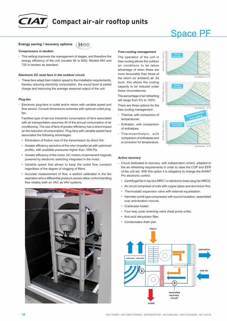
Active recovery- Circuit dedicated to recovery, with independent control, adapted to
the air refreshing requirements in order to raise the COP and EER of the unit set. With this option it is obligatory to change the AVANT Pro electronic control.
• Centrifugal fan in top box MRC1 or electronic lower plug-fan MRC0.
• Air circuit comprised of coils with copper pipes and aluminium fi ns.
• Thermostatic expansion valve with external equalisation.
• Hermetic scroll-type compressor with sound insulation, assembled over antivibration mounts.
• Crankcase heater.
• Four-way cycle reversing valve (heat pump units).
• Anti-acid dehydrator fi lter.
• Condensates drain pan.
Energy saving / recovery options
Compressors in tandem- This setting improves the management of stages, and therefore the
energy effi ciency of the unit (models 90 to 600). Models 650 and 720 in tandem as standard.
Electronic EC axial fans in the outdoor circuit - These fans adapt their rotation speed to the installation requirements,
thereby reducing electricity consumption, the sound level at partial charge and improving the average seasonal output of the unit.
Plug-fan- Electronic plug-fans in outlet and/or return with variable speed and
fl ow sensor. Consult dimensions schemes with optional outlet plug-fan.
Facilities type of service industries consumption of fans associated with air transportation assumes 40 of the annual consumption of air conditioning. The use of fans of greater effi ciency has a direct impact on the reduction of consumption. Plug-fans with variable speed have associated the following advantages:
• Elimination of friction loss of the transmission by direct link.
• Greater effi ciency aeraulics of the rotor (impeller jet with optimized profi le), with available pressures higher than 1000 Pa.
• Greater effi ciency of the motor, DC motors of permanent magnets powered by electronic switching integrated in the motor.
• Variable speed that allows to keep the outlet flow constant regardless of the degree of clogging of fi lters.
• Accurate measurement of fl ow, a section calibrated in the fan aspiration and a differential pressure sensor allow control handling fl ow reliably both on VAC as VAV systems.
reversiblerecovery
circuit
outlet
return
new air
extraction
Free-cooling managementThe operation of the unit in free-cooling allows the outdoor air conditions to be taken advantage of when these are more favourable than those of the return (or ambient) air. As such, this allows the cooling capacity to be reduced under these circumstances.
The percentage of air refreshing will range from 0% to 100%.
There are three options for the free-cooling management:
- Thermal, with comparison of temperatures.
- Enthalpic, with comparison of enthalpies.
- Thermoentha lp ic , w i th comparison of enthalpies and a correction for temperature.
Spec
ific
hum
idity
Spec
ific
hum
idity
Spec
ific
hum
idity
Dry temperature
Dry temperature
Dry temperature
Thermalfree-cooling
Enthalpicfree-cooling
Thermoenthalpicfree-cooling
Thermoenth
alpic
free-cooling
It saves more energy

HEAT PUMPS - AIR CONDITIONNING - REFRIGERATION - AIR HANDLING - HEAT EXCHANGE - NA 13.644 B
Compact air-air rooftop units
11
Spa
ce P
F
Comfort / indoor air quality options- Gravimetric fi lter G4.
- Gravimetric fi lter G4 of low pressure drop.
- Opacimetric folded fi lters F6 to F9 + gravimetric G4.
- Opacimetric folded fi lters F7 and F9 of low pressure drop + G4 of low pressure drop.
- Double stage creased opacimetric fi lters (F+F standard or F+F of low pressure drop). With this option, a technical consultation must be made due to changes in unit dimensions (models 90 to 180 with MS assembly and top return, models 240 to 1200 with MS assembly and top and bottom return).
Ambientprobe
Ductprobe
- Air quality probe for installation in the environment or in duct to enable measuring CO2 and/or volatile compounds (with AVANT Pro control, instead of the mixing probe).
Creasedopacimetricfi lters
Gravimetricfi lters
Packing options- Maritime packing SEI4C (with or without gas burner).
- Skis for transporting in closed container (models 415 to 1200, except with assemblies MC1 and MRC1).
Service options- Commissioning and extension of guarantee of 1 year (with or without
gas burner) in pieces, workforce and displacement.
- Commissioning and extension of guarantee of 2 years (with or without gas burner) in pieces, workforce and displacement.
Electric panel options- Electrical power supply with neutral.- Numeration of components in the electrical panel.- Numeration of wired.
- Energy meter for monitoring of the power consumption of the installation.
Safety options- Soft starter of the outlet and/or return fan which prolongs the set
time mainly aimed at installations with cloth ducts. Compulsory for motors with an output of 15 kW and above.
- Differential pressostat for the detection of clogged fi lters.
- Differential pressostat for control of air fl ow.
- Smoke detecting station in accordance with the NF S 61-961 standard (with AVANT Pro control).
- Refrigerant leak detector (with AVANT Pro control).
Installation options- Outlet and/or return fan with high pressure available.
- Control of the overpressure with the MC0 and MC1 assemblies.
- Condensates drain pan for the outdoor circuit in galvanised steel (consult dimensions drawing). T h i s o p t i o n i s n o t available for models 240 to 1200 when maritime transport is required by container.
- Outdoor coil protection grille.
- Outdoor coil antihail grille.- Standardised pre-assembly frames made of galvanised steel
panelling, thermally insulated. Adjustable height.
- Adaptation frames for replacing units on site.
- Antivibration mounts made of rubber.

Compact air-air rooftop units
HEAT PUMPS - AIR CONDITIONNING - REFRIGERATION - AIR HANDLING - HEAT EXCHANGE - NA 13.644 B12
Space PF
Comunication
AVANT and AVANT Pro controls allow the connection to a centralised
technical management system by using a specifi c BMS card for some
of the following communication protocols:
- RS485 serial cards for network communication with protocols: Carel, Modbus, LonWorks®, BACnetTM MSTP, Konnex.
- Ethernet pCO Web card for network communication with protocols: Modbus TCP/IP, BACnetTM Ethernet, TCP/IP, SNMP V1-2-3, FTP and HTTP.
With AVANT / AVANT+ electronic controlThe TCO user terminal is available in two confi gurations:
Control / comunication options
With AVANT Pro electronic control- Control without pGD1 terminal (for units with shared terminal).
- Kit remote control to 200 meters (pGD1 terminal + 2 TCONN bypass cards).
- Ambient air temperature probe: compulsory in units with gas burner.
- Ambient air enthalpy probe: compulsory in units with gas burner + enthalpic or thermoenthalpic free-cooling.
- Relative humidity probes of return and outdoor air: compulsory in units with enthalpic or thermoenthalpic free-cooling.
- pGD1 terminal for maintaining of the unit.
- Return or ambient air temperature probe connected to the board that replaces the room probe of the thermostat TCO. This probe is required for fi re safety.
Surface terminalTerminal to fi t
BMSField-Bus
pGD1 terminal
6 5 4 3 2 1 0 6 5 4 3 2 1 0
TCONN
These systems allow the installation in remote management. Through a single connection to the Internet is accessed the information system. The Web interface, which is available for the local user, allows the monitoring and the complete confi guration of the installation: from the offi ce or any other user’s current location.
For remote control of multiple sites, there are dedicated tools for centralized management as RemotePRO and RemoteValue.
Supervision solutions
CIAT has developed different solutions of supervision according to the dimensions of the installation.
• pCO WebIt is the solution for the management and supervision of a single unit if it incorporates the Ethernet pCO Web card.
• PlantVisorPRO2This is the solution for the management and supervision of air-conditioning installations with up to 300 units. It performs advanced monitoring and maintenance functions and enables creating areas and groups which simplify the management of the installation.
PlantVisorPRO2 is available in two versions:
• Box: comprised of the CPU unit and, optionally, by monitor and keyboard.
• Touch: this includes the CPU and the touchscreen in the one device.
In this case, each unit needs one RS485 Carel / Modbus board.
• PlantWatchPRO It is a solution designed for the monitoring of installations of medium - small dimensions, with ability to manage up to 10 units. Suitable for technical environments, it has no parts in movement.
Includes: 5.7 “ touch display, buzzer for notifi cations and 2 USB ports for downloading reports, charge devices models and applying service packs.
In this case, each unit needs one RS485 Carel / Modbus board.
HTTPS
Software for remote center management
pCO Web (1 unit)
PlantWatchPRO (10 units)
PlantVisorPRO2 (300 units)

HEAT PUMPS - AIR CONDITIONNING - REFRIGERATION - AIR HANDLING - HEAT EXCHANGE - NA 13.644 B
Compact air-air rooftop units
13
Spa
ce P
F
TECHNICAL CHARACTERISTICSSpace PF 90 120 160 180 240 320 360 415 420
Coolingcapacities
Cooling capacity (kW) 23,1 31,7 40,3 45,1 60,8 75,6 86,1 92,0 104,4
Power input (kW) 7,1 10,5 14,3 15,5 20,1 28,9 31,5 33,8 30,3
EER performance 3,3 3,0 2,8 2,9 3,0 2,6 2,7 2,7 3,4
Heatingcapacities
Heating capacity (kW) 23,0 30,9 38,8 45,7 61,4 78,4 91,6 98,9 105,1
Power input (kW) 6,2 9,3 11,4 13,1 18,7 24,1 28,1 28,5 28,3
COP performance 3,7 3,3 3,4 3,5 3,3 3,3 3,3 3,5 3,7
Outdoorcircuitfan
Nominal air fl ow (m3/h) 8.000 13.000 17.000 17.000 30.000 30.000 30.000 30.000 42.000
Available static pressure (mm.a.c) 4
Type Axial
Number 1 2
Diameter (mm) 630 800 2 x 800
Output (kW) 0,7 / 0,4 2,0 / 1,3 2 x 2,0 / 1,3
Speed (r.p.m.) 875 / 650 895 / 685 895 / 685
Indoorcircuitoutletfan
Nominal air fl ow (m3/h) 4.000 6.000 8.700 9.000 12.000 14.300 15.900 18.000 18.000
Available static pressure (mm.a.c) 10,0 10,0 10,0 10,0 12,5 12,5 12,5 12,5 12,5
Type Centrifugal
Number / no. turbines 1 / 1 2 / 2
Motor output (kW) 0,75 1,1 2,2 2,2 2,2 4 5,5 2 x 2,2 2 x 1,5
Power input (kW) 0,51 0,92 1,34 1,46 1,81 2,85 3,54 2,72 2,04
Speed (r.p.m.) 864 820 707 725 592 672 696 688 535
Compressor
Type Scroll
Number of compressors 1 2
Number of stages 1 2
Number of circuits 1 2
Oil type Copeland 3MAF 32cST, Danfoss POE 160SZ, ICI Emkarate RL 32CF, Mobil EAL Artic 22CC
Volume of oil (l) 3 3,3 3,3 6,2 2 x 3,3 2 x 3,3 2 x 6,2 2 x 6,2 2 x 6,2
Electricalcharacteristics
Electrical power supply 400 V / III ph / 50 Hz (±10%)
Power supply 3 Wires + Ground
Maximumabsorbedcurrent
Compressor(s) (A) 15,3 20,1 25,1 29,1 40,2 50,2 58,2 70,3 70,3
Outdoor fan(s) (A) 1,3 4,3 4,3 4,3 8,6 8,6 8,6 8,6 8,6
Indoor fan (A) 2,1 2,7 5,0 5,0 5,0 9,0 11,6 10,0 7,1
Control (A) 0,9 0,9 0,9 0,9 1,8 1,8 1,8 1,8 1,8
Total (A) 19,5 27,9 35,2 39,2 55,6 69,6 80,2 90,7 87,8
Refrigerant
Type R-410A
Global warming potential (GWP) 1.720
Charge (kg) 7,6 8,6 9,8 12,9 14,0 16,4 18,5 36,0 32,6
Dimensions
Length (mm) 2.400 2.400 2.400 2.400 2.750 2.750 2.750 3.326 4.816
Width (mm) 1.400 1.400 1.400 1.400 2.115 2.115 2.115 2.205 2.205
Height (mm) 1.497 1.497 1.675 1.675 1.705 1.705 2.005 2.095 1.795
Weight (kg) 508 547 599 647 884 966 1.095 1.541 1.788
Condensate outlet Ø 1 1/4” adaptor
Cooling capacity calculated in accordance with the UNE-EN-14511 standard given for indoor temperature conditions 27ºC, (19ºC WB) and 35ºC outdoor temperature.Heating capacity calculated in accordance with the UNE-EN-14511 standard given for indoor temperature conditions 20ºC and 6ºC WB outdoor temperature.Total power input by compressors and motorised fans under nominal conditions, calculated in accordance with the UNE-EN-14511 standard.Climatic warming potential of a kilogram of fl uorinated greenhouse gas in relation to a kilogram of carbon dioxide over a period of 100 years. In models 160 and 180 with top outlet, the fan and motor have to be changed to one with an output of 3kW.

Compact air-air rooftop units
HEAT PUMPS - AIR CONDITIONNING - REFRIGERATION - AIR HANDLING - HEAT EXCHANGE - NA 13.644 B14
Space PFTECHNICAL CHARACTERISTICS
Space PF 480 485 540 600 650 720 840 960 1100 1200
Coolingcapacities
Cooling capacity (kW) 108,0 112,6 126,2 137,5 152,1 168,7 199,9 218,9 257,5 280,8
Power input (kW) 38,0 34,5 39,6 45,4 48,2 55,6 66,1 75,6 88,2 99,9
EER performance 2,8 3,3 3,2 3,0 3,2 3,0 3,0 2,9 2,9 2,8
Heatingcapacities
Heating capacity (kW) 107,6 114,6 128,7 140,2 158,9 177,1 207,7 230,1 267,6 293,1
Power input (kW) 32,1 32,4 35,5 38,6 43,8 50,0 60,0 67,0 81,9 91,1
COP performance 3,4 3,5 3,6 3,6 3,6 3,5 3,5 3,4 3,3 3,2
Outdoorcircuitfan
Nominal air fl ow (m3/h) 30.000 42.000 42.000 42.000 55.000 56.000 75.000 75.000 112.500 112.500
Available static pressure (mm.a.c) 4
Type Axial
Number 2 2 4 6
Diameter (mm) 2 x 800 2 x 800 2 x 630 + 2 x 800 4 x 800 6 x 800
Output (kW) 2 x 2,0 / 1,3 2 x 2,0 / 1,3 2 x 0,7 / 0,4 + 2 x 2,0 / 1,3 4 x 2,0 / 1,3 6 x 2,0 / 1,3
Speed (r.p.m.) 895 / 685 895 / 705 875 / 650895 / 685 895 / 685 895 / 685
Indoorcircuitoutletfan
Nominal air fl ow (m3/h) 18.200 18.200 20.400 24.000 27.500 30.000 33.000 37.000 42.000 46.000
Available static pressure (mm.a.c) 15,0 15,0 15,0 15,0 17,5 17,5 17,5 17,5 17,5 17,5
Type Centrifugal
Number / no. turbines 2 / 2 3 / 3 1 / 3
Motor output (kW) 2 x 2,2 2 x 1,5 2 x 2,2 2 x 3 2 x 4 2 x 4 3 x 3 3 x 3 18,5 22
Power input (kW) 2,94 2,18 2,88 4,06 5,15 6,21 5,87 7,49 13,47 16,62
Speed (r.p.m.) 717 554 597 639 654 677 729 760 873 916
Compressor
Type Scroll
Number of compressors 2 4
Number of stages 2 4
Number of circuits 2 4
Oil type Copeland 3MAF 32cST, Danfoss POE 160SZ, ICI Emkarate RL 32CF, Mobil EAL Artic 22CC
Volume of oil (l) 2 x 6,2 2 x 6,2 2 x 6,2 2 x 6,2 4 x 3,3 4 x 6,2 4 x 6,2 4 x 6,2 4 x 6,2 4 x 6,2
Electricalcharacteristics
Electrical power supply 400 V / III ph / 50 Hz (±10%)
Power supply 3 Wires + Ground
Maximumabsorbedcurrent
Compressor(s) (A) 79,6 79,6 91,1 102,6 100,4 122,0 140,6 159,2 182,2 205,2
Outdoor fan(s) (A) 8,6 8,6 8,6 8,6 11,2 11,2 17,2 17,2 25,8 25,8
Indoor fan (A) 10,0 7,1 10,0 13,8 18,0 18,0 20,7 20,7 37,0 42,0
Control (A) 1,8 1,8 1,8 1,8 1,8 1,8 1,8 1,8 1,8 1,8
Total (A) 100,0 97,1 111,5 126,8 131,4 153,0 180,3 198,9 246,8 274,8
Refrigerant
Type R-410A
Global warming potential (GWP) 1.720
Charge (kg) 36,5 33,0 34,0 35,0 35,0 41,0 44,0 46,0 57,0 58,0
Dimensions
Length (mm) 3.326 4.816 4.816 4.816 4.816 4.816 4.816 4.816 6.316 6.316
Width (mm) 2.205 2.205 2.205 2.205 2.205 2.205 2.205 2.205 2.205 2.205
Height (mm) 2.095 1.795 1.795 1.795 2.095 2.095 2.095 2.095 2.095 2.095
Weight (kg) 1.581 1.830 1.879 1.937 2.093 2.152 2.277 2.374 3.022 3.135
Condensate outlet Ø 1 1/4” adaptor
Cooling capacity calculated in accordance with the UNE-EN-14511 standard given for indoor temperature conditions 27ºC, (19ºC WB) and 35ºC outdoor temperature.Heating capacity calculated in accordance with the UNE-EN-14511 standard given for indoor temperature conditions 20ºC and 6ºC WB outdoor temperature.Total power input by compressors and motorised fans under nominal conditions, calculated in accordance with the UNE-EN-14511 standard.Climatic warming potential of a kilogram of fl uorinated greenhouse gas in relation to a kilogram of carbon dioxide over a period of 100 years.

Compact air-air rooftop units
HEAT PUMPS - AIR CONDITIONNING - REFRIGERATION - AIR HANDLING - HEAT EXCHANGE - NA 13.644 B16
Space PFOPTIONS FOR THE INDOOR CIRCUIT
Space PF 90 120 160 180 240 320 360 415 420
Nominal air fl ow (m3/h) 4.000 6.000 8.700 9.000 12.000 14.300 15.900 18.000 18.000
Nominal available static pressure (mm.a.c.) 10,0 10,0 10,0 10,0 12,5 12,5 12,5 12,5 12,5
Standardpressure
Nominal absorbed output (kW) 0,38 0,79 1,06 1,16 1,62 2,44 2,80 2,22 2,22
Max. available static pressure (mm.a.c.) 93,0 78,6 85,7 84,1 80,5 63,4 55,2 83,2 83,5
Number 1 2 3
Diameter (mm) 500 500 500
Output (kW) 1 x 2,68 2 x 2,68 3 x 2,68
Speed (r.p.m.) 1 x 1.700 2 x 1.700 3 x 1.700
Maximum absorbed current (A) 4,2 8,4 12,5
Highpressure(optional)
Nominal absorbed output (kW) -- 1,53 2,28 2,56 --
Max. available static pressure (mm.a.c.) -- 142,6 131,4 127,2 --
Number -- 2 --
Diameter (mm) -- 500 --
Output (kW) -- 2 x 5,5 --
Speed (r.p.m.) -- 2 x 2.200 --
Maximum absorbed current (A) -- 16,8 --
Space PF 480 485 540 600 650 720 840 960 1100 1200
Nominal air fl ow (m3/h) 18.200 18.200 20.400 24.000 27.500 30.000 33.000 37.000 42.000 46.000
Nominal available static pressure (mm.a.c.) 15,0 15,0 15,0 15,0 17,5 17,5 17,5 17,5 17,5 17,5
Standardpressure
Nominal absorbed output (kW) 2,46 2,43 3,12 3,72 4,49 5,34 6,03 7,57 8,73 10,55
Max. available static pressure (mm.a.c.) 82,2 82,5 73,4 77,5 72,7 63,5 69,2 57,0 59,7 48,3
Number 3 4 5 6
Diameter (mm) 500 500 500 500
Output (kW) 3 x 2,68 4 x 2,68 5 x 2,68 6 x 2,68
Speed (r.p.m.) 3 x 1.700 4 x 1.700 5 x 1.700 6 x 1.700
Maximum absorbed current (A) 12,5 16,7 20,9 25,1
Highpressure(optional)
Nominal absorbed output (kW) -- 2,92 4,00 4,08 4,81 5,45 6,78 7,87 9,39
Max. available static pressure (mm.a.c.) -- 139,9 127,9 118,7 107,2 123,2 108,3 116,4 103,3
Number -- 3 3 4 5
Diameter (mm) -- 500 560 560 560
Output (kW) -- 3 x 5,5 3 x 4,7 4 x 4,7 5 x 4,7
Speed (r.p.m.) -- 3 x 2.200 3 x 1.750 4 x 1.750 5 x 1.750
Maximum absorbed current (A) -- 25,2 21,9 29,2 36,5
Outlet plug-fan of variable speed

HEAT PUMPS - AIR CONDITIONNING - REFRIGERATION - AIR HANDLING - HEAT EXCHANGE - NA 13.644 B
Compact air-air rooftop units
17
Spa
ce P
F
Axial extraction fan (ME assembly)
Axial return fan (MA assembly)
Space PF 90 120 160 180 240 320 360 415 420
Nominal air fl ow (m3/h) 2.000 3.000 4.350 4.500 6.000 7.150 7.950 9.000 9.000
Number 1 2
Diameter (mm) 450
Power supply voltage 230 V / I ph / 50 Hz
Output (kW) 0,48 2 x 0,48
Speed (r.p.m.) 1.350
Maximum absorbed current (A) 2,1 4,2
Space PF 480 485 540 600 650 720 840 960 1100 1200
Nominal air fl ow (m3/h) 9.100 9.100 10.200 12.000 13.750 15.000 16.500 18.500 21.000 23.000
Number 2 3 4
Diameter (mm) 450
Power supply voltage 230 V / I ph / 50 Hz
Output (kW) 2 x 0,48 3 x 0,48 4 x 0,48
Speed (r.p.m.) 1.350
Maximum absorbed current (A) 4,2 6,3 8,4
Space PF 90 120 160 180 240 320 360 415 420
Maximum air fl ow (m3/h) 4.000 6.000 8.700 9.000 12.000 12.400 12.400 18.000 18.000
Number 2 3 4
Diameter (mm) 450 500
Power supply voltage 230 V / I ph / 50 Hz
Output (kW) 2 x 0,48 3 x 0,64 4 x 0,64
Speed (r.p.m.) 1.350 1.270
Maximum absorbed current (A) 4,2 9,0 12,0
Space PF 480 485 540 600 650 720 840 960 1100 1200
Maximum air fl ow (m3/h) 18.200 18.200 20.400 24.000 27.500 30.000 30.000 30.000 37.500 37.500
Number 3 4 5
Diameter (mm) 500
Power supply voltage 230 V / I ph / 50 Hz
Output (kW) 3 x 0,64 4 x 0,64 5 x 0,64
Speed (r.p.m.) 1.270
Maximum absorbed current (A) 9,0 12,0 15,0

Compact air-air rooftop units
HEAT PUMPS - AIR CONDITIONNING - REFRIGERATION - AIR HANDLING - HEAT EXCHANGE - NA 13.644 B18
Space PFLower return plug-fan of variable speed (MC0 assembly)
Space PF 90 120 160 180 240 320 360 415 420
Nominal air fl ow (m3/h) 4.000 6.000 8.700 9.000 12.000 14.300 14.600 18.000 18.000
Nominal available static pressure (mm.a.c.) 10,0 10,0 10,0 10,0 12,5 12,5 12,5 12,5 12,5
Nominal absorbed output (kW) 0,28 0,54 1,15 1,24 1,19 1,64 2,03 2,64 2,64
Maximum available static pressure (mm.a.c.) 98,7 90,1 57,7 52,1 90,1 79,0 68,9 52,1 52,1
Number x Diameter (mm) 1 x 500 2 x 500
Output (kW) 2,68 2 x 2,68
Speed (r.p.m.) 1.700 2 x 1.700
Maximum absorbed current (A) 4,2 8,4
Space PF 480 485 540 600 650 720 840 960 1100 1200
Nominal air fl ow (m3/h) 18.200 18.200 20.400 24.000 27.500 30.000 33.000 34.600 42.000 46.000
Nominal available static pressure (mm.a.c.) 15,0 15,0 15,0 15,0 17,5 17,5 17,5 17,5 17,5 17,5
Nominal absorbed output (kW) 2,86 2,86 2,43 3,29 4,59 4,15 4,96 6,23 8,17 8,52
Maximum available static pressure (mm.a.c.) 50,1 50,1 83,0 68,3 48,8 74,8 64,5 47,3 104,0 95,2
Number x Diameter (mm) 2 x 500 3 x 500 4 x 500 4 x 560
Output (kW) 2 x 2,68 3 x 2,68 4 x 2,68 4 x 4,7
Speed (r.p.m.) 3 x 1.700 3 x 1.700 4 x 1.700 4 x 1.750
Maximum absorbed current (A) 8,4 12,5 16,7 25,2
Centrifugal return fan in top box (MC1 assembly)
Note: Consult the tables of selection and fan performance curves for these fans on pages 128 to 131 of this brochure.
Space PF 90 120 160 180 240 320 360 415 420
Nominal air fl ow (m3/h) 4.000 6.000 8.700 9.000 12.000 14.300 15.900 18.000 18.000
Available static pressure (mm.a.c.) 10,0 10,0 10,0 10,0 12,5 12,5 12,5 12,5 12,5
Nominal absorbed output (kW) 0,30 0,70 1,04 1,13 1,43 2,14 2,76 2,50 1,76
Number / no. turbines 1 / 1 2 / 2
Output (kW) 0,55 1,1 1,5 1,5 2,2 3 4 2 x 1,5 2 x 1,1
Speed (r.p.m.) 585 671 583 593 503 547 581 634 488
Maximum absorbed current (A) 1,6 2,7 3,6 3,6 5,0 6,9 9,0 7,2 5,4
Space PF 480 485 540 600 650 720 840 960 1100 1200
Nominal air fl ow (m3/h) 18.200 18.200 20.400 24.000 27.500 30.000 33.000 37.000 42.000 46.000
Available static pressure (mm.a.c.) 15,0 15,0 15,0 15,0 17,5 17,5 17,5 17,5 17,5 17,5
Nominal absorbed output (kW) 2,56 1,80 2,28 3,22 4,32 5,25 4,10 5,14 10,05 13,05
Number / no. turbines 2 / 2 3 / 3 1 / 3
Output (kW) 2 x 2,2 2 x 1,1 2 x 1,5 2 x 2,2 2 x 3 2 x 4 3 x 2,2 3 x 2,2 15 18,5
Speed (r.p.m.) 673 489 509 546 577 600 536 554 709 770
Maximum absorbed current (A) 10,0 5,4 7,2 10,0 13,8 18,0 15,0 15,0 29,0 37,0

HEAT PUMPS - AIR CONDITIONNING - REFRIGERATION - AIR HANDLING - HEAT EXCHANGE - NA 13.644 B
Compact air-air rooftop units
19
Spa
ce P
FNote: With this option, it is obligatory to change to AVANT Pro electronic control.
MRC cooling recovery circuit
Space PF 90 120 160 180 240 320 360 415 420
MRC0Nominal fl ow (m3/h) 4.000 6.000 8.700 9.000 12.000 14.300 15.900 18.000 18.000
Available static pressure in return (mm.c.a) 96,4 85,9 50,3 44,3 81,0 69,1 58,3 45,3 49,1
MRC1Nominal fl ow (m3/h) 4.000 6.000 8.700 9.000 12.000 14.300 15.900 18.000 18.000
Available static pressure in return (mm.c.a) 10,0 10,0 10,0 10,0 12,5 12,5 12,5 12,5 12,5
Recoverycompressorcharacteristics
Type Scroll
No. of compressors / circuits 1 / 1
Oil type Copeland 3MAF 32cST, Danfoss POE 160SZ, ICI Emkarate RL 32CF, Mobil EAL Artic 22CC
Volume of oil (l) 1,1 1,6 3,0
Maximum absorbed current (A) 6,3 9,0 15,3
Refrigerant charge R-410A (kg) 2,6 2,7 3,3 3,3 6,1 6,1 6,2 8,0 8,0
Space PF 480 485 540 600 650 720 840 960 1100 1200
MRC0Nominal fl ow (m3/h) 18.200 18.200 20.400 24.000 27.500 30.000 33.000 37.000 42.000 46.000
Available static pressure in return (mm.c.a) 43,1 47,0 77,8 63,6 40,7 68,2 56,8 38,3 88,8 79,8
MRC1Nominal fl ow (m3/h) 18.200 18.200 20.400 24.000 27.500 30.000 33.000 37.000 42.000 46.000
Available static pressure in return (mm.c.a) 15,0 15,0 15,0 15,0 17,5 17,5 17,5 17,5 1,75 17,5
Recoverycompressorcharacteristics
Type Scroll
No. of compressors / circuits 1 / 1
Oil type Copeland 3MAF 32cST, Danfoss POE 160SZ, ICI Emkarate RL 32CF, Mobil EAL Artic 22CC
Volume of oil (l) 3,0 3,3 4 6,2 6,2
Maximum absorbed current (A) 15,3 20,1 25,1 30,5 39,8
Refrigerant charge R-410A (kg) 8,0 8,0 8,1 8,2 7,6 7,7 7,1 7,1 8,2 8,2
Montaje MRC00 Montaje MRC11

Compact air-air rooftop units
HEAT PUMPS - AIR CONDITIONNING - REFRIGERATION - AIR HANDLING - HEAT EXCHANGE - NA 13.644 B20
Space PFHot water auxiliary coil
Position of the hydraulic connections of the hot water auxiliary coil (optional)
A B
C
21
Note: The input / output connections of the coil are located inside the unit.
The connection can be established via the unit base using fl exible tubing or via the side panel. In the above diagram, the position of the sheet metal precuts is shown on the side panel.
To connections for the base to consult pre-assembly frames schemes.
Space PF 90 120 160 180 240 320 360 415 420
Air pressure drop (mm.a.c.) 1,8 3,5 3,6 3,9 3,5 4,6 4,0 2,7 2,1
Water 80/60ºC and inlet air 20ºC
Heating capacity (kW) 24,6 31,8 44,0 45,0 104,0 115,4 140,7 146,3 181,2
Water fl ow (m3/h) 1,1 1,4 2,0 2,0 4,6 5,1 6,2 6,5 8,0
Water pressure drop (m.w.c) 0,7 1,1 1,0 1,0 1,7 1,6 3,5 1,7 2,0
Water 90/70ºC and inlet air 20ºC
Heating capacity (kW) 30,4 39,4 54,6 55,7 129,0 143,3 172,6 179,8 223,1
Water fl ow (m3/h) 1,4 1,8 2,4 2,5 5,7 6,4 7,7 8,0 9,9
Water pressure drop (m.w.c) 1,0 1,4 1,2 1,2 2,0 2,5 5,0 2,6 2,4
Weight (empty) (kg) 11,1 11,1 15,1 15,4 34,8 34,8 41,7 43,0 66,9
Space PF 480 485 540 600 650 720 840 960 1100 1200
Air pressure drop (mm.a.c.) 2,7 2,1 2,5 3,3 2,9 3,4 4,0 4,8 4,5 5,3
Water 80/60ºC and inlet air 20ºC
Heating capacity (kW) 147,3 182,5 196,0 216,3 255,0 268,7 284,3 303,8 326,7 352,4
Water fl ow (m3/h) 6,5 8,1 8,7 9,2 11,3 11,9 12,6 13,5 14,4 15,6
Water pressure drop (m.w.c) 1,8 2,0 1,9 2,3 3,1 3,4 3,8 4,4 2,1 2,4
Water 90/70ºC and inlet air 20ºC
Heating capacity (kW) 181,1 224,7 241,5 266,9 314,5 331,6 351,0 375,3 403,3 436,6
Water fl ow (m3/h) 8,0 10,0 10,7 11,9 14,0 14,7 15,6 16,7 17,9 19,3
Water pressure drop (m.w.c) 2,6 2,5 2,8 3,5 3,9 4,3 4,8 5,5 3,2 3,7
Weight (empty) (kg) 43,0 66,9 66,9 66,9 82,3 82,3 82,3 82,3 82,3 82,3
LEGEND
1 Water outlet
2 Water inlet
Note: With stop-drop in the indoor air coil it is not possible to assemble the hot water coil.
Note: This option always incorporates an antigel thermostat as safety system.
Space PF A(mm)
B(mm)
C(mm)
Ø hydraulic connections: I/O
90 / 120 203 190 177 1 1/4”
160 / 180 203 190 177 1 1/2”
240 / 320 295 250 177 2”
360 295 250 177 2”
415 / 420 / 480 / 485 / 540 / 600 302 250 222 2”
650 / 720 / 840 / 960 302 250 222 2”
1100 / 1200 302 250 222 2 1/2”

HEAT PUMPS - AIR CONDITIONNING - REFRIGERATION - AIR HANDLING - HEAT EXCHANGE - NA 13.644 B
Compact air-air rooftop units
21
Spa
ce P
F
Electrical heaterNot available for models 90 to 180 with top outlet.
With this option, the air fl ow controller is compulsory, if the unit does not incorporate outlet plug-fan.
Nevertheless, if the unit incorporates outlet plug-fan, it is not possible to select the optional the air fl ow controller, since the proper fan realizes this function.
Auxiliary 2-stage electrical heaters for assembly and connection inside the unit:
Stop-drop in the indoor air coil
Air fl ow at which it is recommended to install a stop-drop in the indoor coil (included in models 1100 and 1200).
Note: For operating conditions with high dehumidifi cation in the indoor coil (e.g. in installations close to the coast) it may be necessary to install a separator even if the fl ow is less than the previous one.
Note: With hot water coil it is not possible to assemble the stop-drop.
Space PFTotal output (kW) 12 18 27 36 45 54 72 90
Stage power (kW) 6 + 6 9 + 9 9 + 18 18 + 18 18 + 27 27 + 27 36 + 36 45 + 45
Current (A)(400V / IIIph / 50Hz)
Outletcentrifugalfan
90 / 120 17,3 26,0 unavailable
160 / 180 17,3 26,0 39,0 unavailable
240 / 320 unavail. 26,0 39,0 52,0 unavailable
360 unavail. 26,0 39,0 52,0 65,0 unavailable
415 / 420 / 480 / 485 unavailable 39,0 52,0 65,0 78,0 unavailable
540 unavailable 39,0 52,0 65,0 78,0 104,0 no disp.
600 unavailable 52,0 65,0 78,0 104,0 no disp.
650 / 720 unavailable 65,0 78,0 104,0 no disp.
840 / 960 / 1100 / 1200 unavailable 65,0 78,0 104,0 130,0
Outletplug-fan
90 / 120 17,3 26,0 unavailable
160 / 180 17,3 26,0 39,0 unavailable
240 / 320 unavail. 26,0 39,0 52,0 unavailable
360 unavail. 26,0 39,0 52,0 65,0 unavailable
415 / 480 unavailable 39,0 52,0 65,0 unavailable
420 / 485 / 540 unavailable 39,0 unavailable
600 unavailable 52,0 65,0 unavailable
650 / 720 unavailable 65,0 78,0 unavailable
840 / 960 / 1100 / 1200 unavailable 65,0 78,0 unavailable
Module weight (kg) 10,7 14,6 19,4 24,1 28,9 33,6 48,3 57,7
Space PF 90 120 160 180 240 320 360 415 420
Air fl ow (m3/h) 7.280 7.280 10.190 10.190 14.560 14.560 17.480 27.700 30.090
Space PF 480 485 540 600 650 720 840 960 1100 1200
Air fl ow (m3/h) 27.700 30.090 30.090 30.090 37.030 37.030 37.030 37.030 Included as standard

Compact air-air rooftop units
HEAT PUMPS - AIR CONDITIONNING - REFRIGERATION - AIR HANDLING - HEAT EXCHANGE - NA 13.644 B22
Space PFGas burnerNatural or propane gas burner with proportional 0-10V actuator. Condensation boiler with premixing and modulation technology that allows outputs close to 105% with regard to the lower heating value (LHV).
The AVANT Pro control (compulsory for gas burners) shall manage the connection of the burner, in heating mode, via an ON/OFF signal.
- In cooling-only devices, the control will activate the burner the same way as an electrical heater stage.
- In heat pump units it is possible to select three different operating modes:
• After the compressors as an electrical heater stage.• Instead of the compressors.• Instead of the compressors if the outdoor temperature is less than
the value marked on an outdoor thermostat.The control of the power will be carried out by the burner's own control in accordance with the signal received from the AVANT Pro (0-10V) control.
Note: with the gas burner, the differential pressostat for controlling air fl ow is compulsory. Nevertheless, if the unit with electrical heaters incorporates outlet plug-fan, it is not possible to select the optional the air fl ow controller, since the proper fan realizes this function.
It is also recommended to use the clogged fi lter detection and anti-freeze protection options for the components of the electric panel when experiencing low outdoor temperatures (compulsory if the outdoor temperature is lower than -8ºC WB).
Gas burner models: Technical characteristicsPCH-35 PCH-43 PCH-54 PCH-72 PCH-92 PCH-150 PCH-200
min. max. min. max. min. max. min. max. min. max. min. max. min. max.
EC Mark (PIN) 0694BM3433
Nominal heat capacity (kW) 11,3 38,8 14,8 47,5 15,5 58,0 22,0 78,0 30,0 98,0 44,0 155,0 53,0 215,0
Nominal heat output (kW) 11,7 36,5 15,5 44,8 16,3 54,0 23,1 73,2 31,5 93,4 46,3 145,0 55,7 197,0
Performance (%) 103,5 94,1 105,0 94,3 105,0 93,1 105,0 93,8 105,0 95,3 105,2 93,5 105,1 91,6
Air fl ow (m3/h) 2.100 6.700 2.600 8.200 3.100 10.100 4.200 13.700 5.400 17.200 8.500 27.700 11.500 37.600
Motor output (kW) 0,07 0,07 0,09 2 x 0,09 2 x 0,07 0,4 0,4
Maximum pressure applicable (mm.a.c.) 120
Ø aspiration/discharge pipe (mm) 80/80 80/80 80/80 100/100 100/100 130/130 130/130
Available outlet pressure for smoke(stack connection) (mm.a.c.) 8 12 12 12 12 10 14
G20 methane supply pressure (mm.a.c.) 200
Consumption G20 (15ºC 10,13 m.a.c.) (m3/h) 1,20 4,11 1,57 5,03 1,64 6,14 2,33 8,25 3,18 10,37 4,66 16,40 5,61 22,75
G25 methane supply pressure (mm.a.c.) 250
Consumption G25 (15ºC 10,13 m.a.c.) (m3/h) 1,39 4,77 1,82 5,84 1,91 7,13 2,71 9,59 3,69 12,05 5,41 19,07 6,52 26,45
G30 methane supply pressure (mm.a.c.) 300 - 500
Consumption G30 (15ºC 10,13 m.a.c.) (kg/h) 0,73 2,50 0,95 3,06 1,00 3,73 1,42 5,02 1,93 6,31 2,83 9,97 3,41 13,84
G31 propane supply pressure (mm.a.c.) 300 - 370 - 500
Consumption G31 (15ºC 10,13 m.a.c.) (kg/h) 0,72 2,46 0,94 3,01 0,98 3,68 1,40 4,95 1,90 6,21 2,79 9,83 3,36 13,63
Power supply voltage 230 V / I ph / 50 Hz
Index of protection (IP) IP4xD
Inlet temperature limit (ºC) -15ºC a +60ºC
Available in all models except for 415 and 480. It is not available in assemblies with top outlet either.
Note: Maximum air fl ow calculated for a T = 15ºCand minimum air fl ow calculated for aT = 50ºC

HEAT PUMPS - AIR CONDITIONNING - REFRIGERATION - AIR HANDLING - HEAT EXCHANGE - NA 13.644 B
Compact air-air rooftop units
23
Spa
ce P
F
The following table indicates the type of gas used by the gas burner as a function of the destination country:
Space PF Nominal air fl ow (m3/h)
Pressure drop (mm.a.c)
PCH-35 PCH-43 PCH-54 PCH-72 PCH-92 PCH-150 PCH-200
90 4.000 6,3 -- -- -- -- -- --
120 6.000 11,1 -- -- -- -- -- --
160 8.700 18,7 -- -- -- -- -- --
180 9.000 19,7 -- -- -- -- -- --
240 12.000 -- 16,1 16,1 7,7 -- -- --
320 14.300 -- -- 20,5 9,7 -- -- --
360 15.900 -- -- 23,7 11,1 -- -- --
420 18.000 -- -- 28,1 13,1 10,0 5,6 --
485 18.200 -- -- 28,6 13,3 10,2 5,7 --
540 20.400 -- -- 33,5 15,5 11,9 6,7 --
600 24.000 -- -- -- -- 14,8 8,4 --
650 27.500 -- -- -- -- 17,8 10,2 10,2
720 30.000 -- -- -- -- 20,1 11,5 11,5
840 33.000 -- -- -- -- 22,9 13,2 13,2
960 37.000 -- -- -- -- 26,9 15,5 15,5
1100 42.000 -- -- -- -- -- 18,6 18,6
1200 46.000 -- -- -- -- -- 21,2 21,2
The following table features the pressure drops (mm.a.c) in the burners available for each model:
Country Category Gas Pressure (mm.a.c) Gas Pressure (mm.a.c)
Austria II2H3B/P G20 200 G30/G31 500
Belgium < 70 kW I2E(S)B,I3P G20/G25 200/250 G31 370
Belgium > 70 kW I2E(R)B,I3P G20/G25 200/250 G31 370
Switzerland II2HH3B/P G20 200 G30/G31 500
Germany II2ELL3B/P G20 200 G30/G31 500
Denmark, Finland, Greece, Sweden II2H3B/P G20 200 G30/G31 300
Spain, United Kingdom, Ireland, Portugal II2H3P G20 200 G31 370
Italy II2H3B/P G20 200 G30/G31 300
Russia II2H3B/P G20 200 -- --
France II23SI3P G20/G25 200/250 G31 370
Luxembourg II2E3P G20/G25 200 G31 370/500
Netherlands II2L3B/P G25 250 G30/G31 300
Norway II2H3B/P G20 200 G30/G31 300
Hungary II2HS3B/P G20/G25.1 250 G30/G31 300
Czech Republic II2H3B/P G20 200 G30/G31 300
Cyprus, Malta I3B/P -- -- G30/G31 300
Estonia, Lithuania, Latvia II2H3B/P G20 200 G30/G31 300
Iceland I3P -- -- G31 370
Slovakia II2H3B/P G20 200 G30/G31 300
Slovenia II2H3B/P G20 200 G30/G31 300
Bulgaria, Romania, Turkey II2H3B7P G20 200 G30/G31 300
Poland II2E3B/P G20/GZ350 200/130 G30/G31 360

Compact air-air rooftop units
HEAT PUMPS - AIR CONDITIONNING - REFRIGERATION - AIR HANDLING - HEAT EXCHANGE - NA 13.644 B78
Space PF
YW
VU
TD
PN
O
M
A
E
C
G
JI
H
F
B
18mm
�
a b
Y
Z
SRQ
X
c
ed
1
3 4
2
Space PF A B C D E F G H I J M N O P Q R S T U V W Y c d e
90 to 180 2.346 1.371 536 400 2.220 1.214 2.114 1.112 123 2.014 100 114 1.012 114 1.018 1.104 98 84 373 201 399 157 89 98 124
Frame Space PF - 90, 120, 160 and 180 (mm)
FrameSpace PF
Weight (kg)
Centre of gravity (mm)
Maximumslope
X Y Z a b
90 to 180 189 1.244 685 228 4º (7%) 4º (7%)
LEGEND
In Space PF assemblies with lower discharge (Mwx0) 1)
In Space PF assemblies with lower return (Mw0y) 1)
Electric power supply connection Ø 40mm
Circulation area for the hydraulic connections of the optional hot water auxiliary coil.
1) The available assemblies can be consulted on page 8 of this brochure
PRE-ASSEMBLY FRAMES (OPTIONAL)

HEAT PUMPS - AIR CONDITIONNING - REFRIGERATION - AIR HANDLING - HEAT EXCHANGE - NA 13.644 B
Compact air-air rooftop units
79
Spa
ce P
F
E
D
aA
Y
Z
X
d
c
e3
PN
O
M
G
JI
H
18mm
�Y
WV
UT
SRQ
1
4
2
C
F
Bb
Space PF A B C D E F G H I J M N O P Q R S T U V W Y c d e
240 to 360 2.696 2.055 536 400 2.570 1.929 2.463 1.827 132 2.363 100 114 1.727 114 1.371 1.104 95 90 617 535 496 191 104 224 87
Frame Space PF - 240, 320 and 360 (mm)
FrameSpace PF
Weight (kg)
Centre of gravity (mm)
Maximumslope
X Y Z a b
240 to 360 250 1.431 1.025 298 4º (7%) 4º (7%)
LEGEND
In Space PF assemblies with lower discharge (Mwx0) 1)
In Space PF assemblies with lower return (Mw0y) 1)
Electric power supply connection Ø 64mm
Circulation area for the hydraulic connections of the optional hot water auxiliary coil.
1) The available assemblies can be consulted on page 8 of this brochure

Compact air-air rooftop units
HEAT PUMPS - AIR CONDITIONNING - REFRIGERATION - AIR HANDLING - HEAT EXCHANGE - NA 13.644 B80
Space PF
F
SRQ
YW
DV
UT
C
E
18mm
�
A
G
H
NO
P
L MKI J
Ba b
Y
Z
X
1
2
dc
e
43
Space PF A B C D E F G H I J K L M N O P Q R S T U V W Y c d e
415 / 480 3.238 2.101 536 400 3.112 1.975 3.007 1.873 128 2.146 0 760 103 114 1.773 114 1.248 1.700 164 101 617 539 481 237 818 100 413
420 to 960 4.728 2.101 536 400 4.602 1.975 4.498 1.873 123 2.148 600 1.650 107 114 1.773 114 2.138 2.300 164 101 617 539 481 237 818 100 415
1100 to 1200 6.077 2.101 536 400 5.951 1.975 5.847 1.873 118 2.538 600 2.609 111 114 1.773 114 3.089 2.698 164 101 617 539 481 237 813 100 157
Frame Space PF 415, 420, 480, 485, 540, 600, 650, 720, 840, 960, 1100 and 1200 (mm)
FrameSpace PF
Weight (kg)
Centre of gravity (mm)
Maximum slope
X Y Z a b
415 & 480 290 1.517 940 290 3º (5,2%) 4º (7,0%)
420 to 960 385 2.507 1.050 228 2º (3,5%) 4º (7,0%)
1100 & 1200 475 3.222 1.050 228 1º (1,7%) 2º (3,5%)
LEGEND
In Space PF assemblies with lower discharge (Mwx0) 1)
In Space PF assemblies with lower return (Mw0y) 1)
Electric power supply connection Ø 64mm
Circulation area for the hydraulic connections of the optional hot water auxiliary coil.
1) The available assemblies can be consulted on page 8 of this brochure