space product assurance - esa m&p database server for ... · ecss-q-st-70-01c 15 november 2008...
TRANSCRIPT

ECSS-Q-ST-70-01C 15 November 2008
Space product assurance Cleanliness and contamination control
ECSS Secretariat ESA-ESTEC
Requirements & Standards Division Noordwijk, The Netherlands

ECSS‐Q‐ST‐70‐01C 15 November 2008
Foreword
This Standard is one of the series of ECSS Standards intended to be applied together for the management, engineering and product assurance in space projects and applications. ECSS is a cooperative effort of the European Space Agency, national space agencies and European industry associations for the purpose of developing and maintaining common standards. Requirements in this Standard are defined in terms of what shall be accomplished, rather than in terms of how to organize and perform the necessary work. This allows existing organizational structures and methods to be applied where they are effective, and for the structures and methods to evolve as necessary without rewriting the standards.
This Standard has been prepared by the ECSS‐Q‐ST‐70‐01 Working Group, reviewed by the ECSS Executive Secretariat and approved by the ECSS Technical Authority.
Disclaimer
ECSS does not provide any warranty whatsoever, whether expressed, implied, or statutory, including, but not limited to, any warranty of merchantability or fitness for a particular purpose or any warranty that the contents of the item are error‐free. In no respect shall ECSS incur any liability for any damages, including, but not limited to, direct, indirect, special, or consequential damages arising out of, resulting from, or in any way connected to the use of this Standard, whether or not based upon warranty, business agreement, tort, or otherwise; whether or not injury was sustained by persons or property or otherwise; and whether or not loss was sustained from, or arose out of, the results of, the item, or any services that may be provided by ECSS.
Published by: ESA Requirements and Standards Division ESTEC, P.O. Box 299, 2200 AG Noordwijk The Netherlands Copyright: 2008 © by the European Space Agency for the members of ECSS
2

ECSS‐Q‐ST‐70‐01C 15 November 2008
Change log
ECSS‐Q‐70‐01A
11 December 2002
First issue
Transforming ESA PSS‐01‐701 into an ECSS Standard
ECSS‐Q‐70‐01B Never issued
ECSS‐Q‐ST‐70‐01C
15 November 2008
Second issue
The main differences between ECSS‐Q‐70‐01A and this Standard are listed hereunder:
• Reorganization of the document to conform to the ECSS drafting rules (e.g. split of descriptive and normative text), and
• Creation of two DRDs
3
ECSS‐Q‐ST‐70‐01C 15 November 2008
Table of contents
Cleanliness and contamination control ................................................................................1
1 Scope.......................................................................................................................8
2 Normative references.............................................................................................9
3 Terms, definitions and abbreviated terms..........................................................10 3.1 Terms from other standards .....................................................................................10 3.2 Terms specific to the present standard ....................................................................10 3.3 Abbreviated terms ....................................................................................................14
4 Principles ..............................................................................................................16
5 Requirements........................................................................................................17 5.1 Cleanliness and contamination control programme .................................................17
5.1.1 General.......................................................................................................17 5.1.2 Documentation ...........................................................................................17 5.1.3 Contamination budget ................................................................................18 5.1.4 Contamination predictions ..........................................................................18 5.1.5 Contamination prediction with respect to budget........................................19 5.1.6 Cleanliness and contamination process flow chart.....................................19
5.2 Phases .....................................................................................................................20 5.2.1 Design ........................................................................................................20 5.2.2 MAIT...........................................................................................................22 5.2.3 pre-launch and launch ................................................................................23 5.2.4 Mission .......................................................................................................24
5.3 Environments ...........................................................................................................25 5.3.1 Cleanrooms ................................................................................................25 5.3.2 Vacuum facilities.........................................................................................33 5.3.3 Other facilities.............................................................................................34
5.4 Activities ...................................................................................................................34 5.4.1 Cleaning of hardware .................................................................................34 5.4.2 Cleanliness monitoring of space hardware.................................................36
4
ECSS‐Q‐ST‐70‐01C 15 November 2008
5.4.3 Cleanliness verification...............................................................................39 5.4.4 Packaging, containerization, transportation, storage..................................42
Annex A (normative) Cleanliness requirement specification (CRS) - DRD ........44
Annex B (normative) Cleanliness and contamination control plan (C&CCP) - DRD ....................................................................................................................47
Annex C (informative) Cleanliness and contamination control process overview...............................................................................................................51
Annex D (informative) Guidelines for general cleanliness and contamination control.........................................................................................52 D.1 General.....................................................................................................................52 D.2 Contamination attributes ..........................................................................................52
D.2.1 Typical contaminants and their sources .....................................................52 D.2.1.1. On ground .....................................................................................................52 D.2.1.2. On launch ......................................................................................................54 D.2.1.3. During mission...............................................................................................55
D.2.2 Transport mechanisms ...............................................................................58 D.2.2.1. Overview .......................................................................................................58 D.2.2.2. Contaminants transport on ground................................................................58 D.2.2.3. Contaminants transport in space ..................................................................58
D.2.3 Main effects of contamination on space systems .......................................59
Annex E (informative) Cleanliness-oriented design............................................61
Annex F (informative) Modelling guidelines ........................................................63
Annex G (informative) Airborne particulate cleanliness classes equivalence..........................................................................................................64
Annex H (informative) Particulate levels on surfaces .........................................65 H.1 Standard method 1: Particle distribution ..................................................................65 H.2 Standard method 2: Obscuration factor ...................................................................65
H.2.1 Overview.....................................................................................................65 H.2.2 Correlation for particles on surfaces...........................................................65
Annex I (informative) Compatibility of various solvents with listed materials ..............................................................................................................67
Annex J (informative) evaporation residue of commercially available solvents................................................................................................................69
Annex K (informative) Molecular contaminant content of some wipe materials ..............................................................................................................70
Annex L (informative) Effects of humidity on materials and components ........71
5
ECSS‐Q‐ST‐70‐01C 15 November 2008
Annex M (informative) Cleaning methods ............................................................72 M.1 Removal of particulate contamination ......................................................................72
M.1.1 Overview.....................................................................................................72 M.1.2 Vacuum cleaning and wiping......................................................................72 M.1.3 Gas jet cleaning..........................................................................................72 M.1.4 Tapes and films trapping ............................................................................73
M.2 Removal of molecular contamination .......................................................................73 M.2.1 Overview.....................................................................................................73 M.2.2 Mechanical cleaning ...................................................................................73 M.2.3 Solvent and detergent cleaning ..................................................................73 M.2.4 Films trapping .............................................................................................73 M.2.5 Gas jet cleaning..........................................................................................73 M.2.6 Plasma cleaning .........................................................................................74 M.2.7 Bakeout ......................................................................................................74 M.2.8 Ultra-violet-ozone cleaning .........................................................................74
Figures Figure 5-1: Graphical representation of ISO-class concentration limits for selected ISO
classes.................................................................................................................27 Figure C-1 : Cleanliness and contamination control process overview..................................51 Tables Table 5-1: Outgassing criteria for materials in the vicinity of sensitive items around RT .......21 Table 5-2: Outgassing criteria for materials in the vicinity of sensitive items at
temperature below RT .........................................................................................21 Table 5-3: Outgassing criteria for materials in the vicinity of cryogenic surfaces...................21 Table 5-4: Selected airborne particulate cleanliness classes for cleanrooms and other
controlled environment ........................................................................................28 Table 5-5: Correlation airborne and PFO for cleanrooms ......................................................29 Table G-1 : Classification system...........................................................................................64 Table H-1 : Correlation between ideal class of IEST-STD-CC1246D and obscuration
factor....................................................................................................................66 Table I-1 : Examples of compatibility of various solvents with listed materials ......................68 Table J-1 : Commercially available solvents evaporation residue..........................................69 Table K-1 : Molecular contaminant content of some wipe materials ......................................70 Table L-1 : Effect of humidity on materials and components .................................................71
6
ECSS‐Q‐ST‐70‐01C 15 November 2008
Introduction
The objective of this Standard is to ensure a successful mission by the definition of acceptable contamination levels for space system elements, their achievement, and maintenance, throughout
• performance assessment versus contamination,
• facilities and tools definition for contamination control and monitoring,
• materials and processes selection, and
• planning of activities.
7
ECSS‐Q‐ST‐70‐01C 15 November 2008
1 Scope
The purpose of this standard is to define:
• The selection of critical items, the definition of cleanliness requirements to satisfy the mission performance requirements and control the levels to be met by personnel, items, facilities and operations of space projects.
• The management, including organization, reviews and audits, acceptance status and documentation control.
It covers design, development, production, testing, operation of space products, launch and mission.
In this standard are also guidelines given for identification of possible failures and malfunctions due to contamination and guidelines for achieving and maintaining the required cleanliness levels during ground activities, launch and mission.
This Standard applies to all types and combinations of projects, organizations and products, and during all the project phases, except manned missions.
It also applies to those ground systems that have a hardware interface to space systems, such as MGSE integration stands.
This Standard does not address magnetic, electrical or electrostatic cleanliness.
This Standard does not address completely biocontamination aspects. However, references to relevant ECSS standards are provided.
This standard may be tailored for the specific characteristic and constrains of a space project in conformance with ECSS‐S‐ST‐00.
8

ECSS‐Q‐ST‐70‐01C 15 November 2008
2 Normative references
The following normative documents contain provisions which, through reference in this text, constitute provisions of this ECSS Standard. For dated references, subsequent amendments to, or revision of any of these publications do not apply, However, parties to agreements based on this ECSS Standard are encouraged to investigate the possibility of applying the more recent editions of the normative documents indicated below. For undated references, the latest edition of the publication referred to applies.
ECSS‐S‐ST‐00‐01 ECSS system — Glossary of terms
ECSS‐Q‐ST‐10‐09 Space product assurance – Nonconformance control system
ECSS‐Q‐ST‐20 Space product assurance — Quality assurance
ECSS‐Q‐ST‐20‐07 Space product assurance — Quality assurance for test centres
ECSS‐Q‐ST‐70 Space product assurance — Materials, mechanical parts and processes
ECSS‐Q‐ST‐70‐02 Space product assurance — Thermal vacuum outgassing test for the screening of space materials
ECSS‐Q‐ST‐70‐29 Space product assurance — Determination of offgassing products from materials and assembled articles to used in manned space vehicle crew compartment
ECSS‐Q‐ST‐70‐50 Space product assurance — Particle contamination monitoring for spacecraft systems and cleanrooms
ECSS‐Q‐ST‐70‐53 Space product assurance — Material and hardware compatibility test for sterilization processes
ECSS‐Q‐ST‐70‐55 Space product assurance — Microbial examination of flight hardware and cleanrooms
ECSS‐Q‐ST‐70‐58 Space product assurance — Bioburden control of cleanrooms
ISO 14644 Cleanrooms and associated controlled environments
IEST‐STD‐CC1246D Product cleanliness levels and contamination control program
9

ECSS‐Q‐ST‐70‐01C 15 November 2008
3 Terms, definitions and abbreviated terms
3.1 Terms from other standards For the purpose of this Standard, the terms and definitions from ECSS‐ST‐00‐01 and ECSS‐Q‐ST‐70 apply.
3.2 Terms specific to the present standard 3.2.1 airborne particle particle suspended in air
3.2.2 airborne particle cleanliness class level of cleanliness specified by the maximum allowable number of particles per cubic metre (or cubic foot) of air
3.2.3 bakeout activity of increasing the temperature of hardware to accelerate its outgassing rates with the intent of reducing the content of molecular contaminants within the hardware
NOTE Bakeout is usually performed in a vacuum environment, but can be done in a controlled atmosphere.
3.2.4 biocontamination contamination of materials, devices, individuals, surfaces, liquids, gases or air with viable particles
[ISO 14698‐1:2003, 3.1.4] [ISO 14698‐2:2003, 3.4]
3.2.5 cleaning actions to reduce the contamination level
3.2.6 cleanliness (contamination) control any organized action to control the level of contamination
3.2.7 cleanliness level quantitative level of contamination
10
ECSS‐Q‐ST‐70‐01C 15 November 2008
3.2.8 cleanliness verification activity intended to verify that the actual cleanliness conditions of the space system, the cleanrooms or the vacuum chambers are in conformance with the applicable specifications and other cleanliness requirements
3.2.9 cleanroom room in which the concentration of airborne particles is controlled, and which is constructed and used in a manner to minimize the introduction, generation and retention of particles inside the room, and in which other relevant parameters, e.g. temperature, humidity and pressure, are controlled as necessary
[ISO 14644‐6]
3.2.10 clean zone dedicated space in which the concentration of airborne particles is controlled, and which is constructed and used in a manner to minimize the introduction, generation and retention of particles inside the room, and in which other relevant parameters, e.g. temperature, humidity and pressure, are controlled as necessary
[ISO 14644‐6] NOTE This zone can be open or enclosed and can or can
not be located within a cleanroom.
3.2.11 contaminant any unwanted molecular or particulate matter (including microbiological matter) on the surface or in the environment of interest, that can affect or degrade the relevant performance or life time
3.2.12 contaminate, to act of introducing any contaminant
3.2.13 contamination budget permissible contamination levels defined at different stages of the life of the instrument and satellite
3.2.14 contamination potential potential amount of contaminant in the source which can produce contamination
3.2.15 controlled area environmentally controlled area, operated as a cleanroom, with two pre‐filter stages but without the final stage of HEPA (or better) filters used in cleanrooms
3.2.16 fibre particle with a length to diameter ratio of 10 or more
11

ECSS‐Q‐ST‐70‐01C 15 November 2008
3.2.17 FTIR spectrometer analyser (chemical identification) of organic and inorganic contamination using infrared wavelengths
3.2.18 HEPA particle filter throwaway, extended‐medium, dry type filter in a rigid frame that has a minimum particle‐collection efficiency of 99,97 % (that is a maximum particle penetration of 0,03 %) for 0,3 μm thermally generated DOP or specified alternative aerosol
3.2.19 induced contaminant environment environment created by the presence of contaminating items
3.2.20 molecular contamination airborne or surface contamination (vapour, gas, liquid, or solid) without observable dimensions (i.e. with dimensions at molecular level)
3.2.21 monitoring to perform routine, quantitative measurements of environmental parameters in and around cleanrooms, clean zones, and other clean areas, including contamination parameters
3.2.22 non-volatile residue (NVR) quantity of residual soluble, suspended, and particulate matter remaining after the controlled evaporation of a volatile liquid at a specified temperature
3.2.23 obscuration factor (OF) ratio of the projected area of all particles to the total surface area on which they rest
3.2.24 offgassing evolution of gaseous products from a liquid or solid material into an atmosphere
3.2.25 outgassed quantity total quantity of outgassed species expressed as a mass (e.g. gram or percent of the initial specimen) or as pressure × volume (e.g. hPa × m3)
3.2.26 outgassing evolution of gaseous species from a material, usually in vacuum
NOTE Outgassing also occurs in a higher‐pressure environment.
3.2.27 particle unit of matter with observable length, width and thickness
3.2.28 particle fallout accumulated deposit of particulate matter on a surface
12
ECSS‐Q‐ST‐70‐01C 15 November 2008
3.2.29 particle size apparent maximum linear dimension of a particle in the plane of observation as observed with an optical microscope, or the equivalent diameter of a particle detected by automatic instrumentation
NOTE The equivalent diameter is the diameter of a reference sphere having known properties and producing the same response in the sensing instrument as the particle being measured.
3.2.30 particulate of or relating to minute separate particles
3.2.31 particulate contamination (PAC) airborne or surface contamination due to particles
3.2.32 plume exhaust (molecules or particles) of thrusters and engines
3.2.33 purging supply of clean gas to protect the critical hardware from contamination
3.2.34 quartz crystal microbalance (QCM) device for measuring small quantities of mass deposited on a quartz crystal using the properties of a crystal oscillator
3.2.35 ram direction in the direction of velocity vector
3.2.36 sensitive item item whose contamination may affect its performance or life time
3.2.37 ULPA particle filter throwaway, extended‐medium, dry‐type filter in a rigid frame that has a minimum particle‐collection efficiency of 99,999 % (that is, a maximum particle penetration of 0,001 %) for particles in the size range of 0,1 μm to 0,2 μm
3.2.38 venting conveying unwanted gaseous products through an aperture
3.2.39 visibly clean absence of surface contamination when examined with a specific light source, angle of incidence and viewing distance using normal or magnified vision
3.2.40 wake direction direction opposite to the velocity vector
13

ECSS‐Q‐ST‐70‐01C 15 November 2008
3.2.41 witness sample sample used to collect contaminants during exposure, usually in an environmentally controlled area, and then analysed or measured
3.3 Abbreviated terms For the purpose of this Standard, the abbreviated terms from ECSS‐S‐ST‐00‐01 and the following apply:
Abbreviation Meaning
ACS American Chemical Society
AIT assembly, integration and testing
AIV assembly, integration and verification
AO atomic oxygen
BOL beginning of life
CC contamination control
C&CCP cleanliness and contamination control plan
CRS cleanliness requirement specification
CVCM collected volatile condensable material
DIW deionised water
DML declared materials list
DOP dioctylphthalate
ECLS environmental control and life support
EGSE electrical ground support equipment
EMC electromagnetic compatibility
EOL end of life
EVA extra vehicular activity
FTIR Fourier transform infrared
GSE ground support equipment
HEPA high‐efficiency particulate air filter
ICC internal contamination control
IPA isopropyl alcohol
IR infrared
LEO low Earth orbit
MGSE mechanical ground support equipment
MLI multi layer insulation
MOC molecular contamination
MRR manufacturing readiness review
14
ECSS‐Q‐ST‐70‐01C 15 November 2008
NVR non‐volatile residue
OF obscuration factor
PAC particulate contamination
PDR product definition review
PFO particle fallout
PMP parts, materials and processes
QCM quartz crystal microbalance
RH relative humidity
RT room temperature
RML recovered mass loss
SRR system requirement review
TB thermal balance
TML total mass loss
TRR test readiness review
TV thermal vacuum
UV ultra‐violet
ULPA ultra‐low‐particle air filter
VBQC vacuum balance quartz crystal
VCM volatile condensable material
15
ECSS‐Q‐ST‐70‐01C 15 November 2008
4 Principles
The cleanliness and contamination control process is applied all along the project life cycle, from the definition of the C&CCP programme during the early phases (see clause 5.1) until its implementation during phases B, C, D, E and F (see clause 5.2) through the systematic verification of the cleanliness requirements baseline including: predictions through contamination modelling and the establishment of agreed procedures (see clause 5.3 and 5.4) for: environments control (see clause 5.3) packaging, containerization, transportation and storage of the space system.
NOTE Figure C‐1 of Annex C gives an overview of an example of a cleanliness and contamination process.
16
ECSS‐Q‐ST‐70‐01C 15 November 2008
5 Requirements
5.1 Cleanliness and contamination control programme
5.1.1 General a. The supplier shall define and implement a cleanliness and contamination
control programme for each level of configuration. NOTE 1 Surveys can also be made to determine the
contamination control requirements, based on mission objectives and scenarios.
NOTE 2 The objective of this programme is, starting from the mission performance requirements, to establish cleanliness and contamination levels to be achieved at different manufacturing, AIT and mission stages.
NOTE 3 In general, the organization of regular workshops dedicated to cleanliness and contamination control for a specific programme is a good practice.
b. The supplier shall establish measures for the coordination and resolution of cleanliness and contamination control issues among the parties involved in the project.
5.1.2 Documentation
5.1.2.1 Contamination requirements specification a. The supplier shall define and document cleanliness requirements in a
cleanliness requirement specification (CRS), in conformance with the DRD in Annex A.
b. The CRS shall be defined as early as possible in the programme, in order to properly address it during the design phase and provided at the latest at SRR, as part of the review data package.
NOTE Cleanliness is of fundamental importance for the space system’s performance.
17

ECSS‐Q‐ST‐70‐01C 15 November 2008
c. The CRS should be prepared in collaboration with users and engineers from the different disciplines.
NOTE Users can be, for example, experimenters or scientists.
d. In case the CRS cannot be produced at an early stage of the design, a cleanliness control policy document shall be used.
NOTE 1 The cleanliness control policy document gives the correlation data between acceptable performance losses and the contamination levels from library search or from tests that are performed.
NOTE 2 The cleanliness control policy document can become the CRS during the development of the design.
5.1.2.2 Contamination and Cleanliness Control Plan a. In reply to the CRS, the supplier shall establish a cleanliness and
contamination control plan (C&CCP) in conformance with the DRD in Annex B (C&CCP DRD), to be provided at the latest at PDR, as part of the review data package.
5.1.3 Contamination budget a. As part of the CRS (see Annex A), a contamination budget (allocations)
shall be established. NOTE This budget determines the maximum allowed on
ground and in‐orbit molecular and particulate contamination levels.
b. The specified contamination levels shall be derived from the acceptable performance losses simulated through dedicated modelling.
5.1.4 Contamination predictions a. As part of the C&CCP (see Annex B), particulate and molecular
contamination predictions shall be established. NOTE Contamination predictions are done in order to
estimate the expected on ground and in‐orbit molecular and particulate contamination levels.
b. These predictions shall be updated to evaluate the molecular and particulate contamination levels generated during all on ground activities and during launch and in‐orbit phases.
NOTE Ground activities can be MAIT, storage, transportation, launch preparation.
c. Modelling techniques shall be used to predict “in orbit“ contamination levels.
NOTE Examples of modelling techniques are given in Annex F.
18

ECSS‐Q‐ST‐70‐01C 15 November 2008
d. For each on ground activity, for launch and in‐orbit phases, the following items shall be identified in the contamination prediction:
1. the seen environment,
2. the sensitive surfaces,
3. the duration of the exposure to this environment, and
4. the potential means of protection.
e. During all on ground activities, the contamination predictions shall be consolidated with the results of molecular and particulate monitoring.
5.1.5 Contamination prediction with respect to budget
a. The contamination predictions for all the different phases shall be compared to the cleanliness requirements, i.e. contamination budget.
NOTE For example, for of such phases are MAIT, BOL and EOL
b. If the contamination predictions or when available actual measurements, result in a higher than the specified level, then corrective actions and precautions to reduce contamination shall be investigated and implemented.
NOTE The linear dependency of MOC and PAC as a function of time is not always valid for longer periods.
5.1.6 Cleanliness and contamination process flow chart
a. The supplier shall establish a contamination and contamination process flow chart.
NOTE An example of cleanliness and contamination process flow chart is given in Figure C‐1 of Annex C.
b. Whenever the CRS requirements are not met, countermeasures should be prioritized from the most to the least preferred.
NOTE The most preferred is categorized as “1”and the least preferred as “4” in the example given in Figure C‐1.
19

ECSS‐Q‐ST‐70‐01C 15 November 2008
5.2 Phases
5.2.1 Design
5.2.1.1 General design aspects a. The level of sensitivity to contamination shall be one of the drivers in the
initial design.
b. The design shall be cleanliness oriented. NOTE 1 A way to implement a cleanliness oriented design
is given in Annex E. NOTE 2 Such design can contribute to achieve the
contamination levels defined by the CRS on ground as well during the launch and mission.
NOTE 3 A way to achieve the target contamination levels can be found in Annex D.
c. When the design baseline is incompatible with cleanliness requirements, the design changes shall be identified and corrective actions shall be taken in close cooperation with all levels involved.
5.2.1.2 Materials selection a. When the offgassing effect of a material is a selection criteria, the supplier
shall apply ECSS‐Q‐ST‐70‐29. NOTE For modelling the molecular contamination during
on‐ground activities, when outgassing data are too conservative, offgassing data are advisable.
b. For the particulate contamination, the supplier shall apply ECSS‐Q‐ST‐70‐50.
c. When the microbiological contamination effect is a selection criteria, the supplier shall apply ECSS‐Q‐ST‐70‐55.
d. When sterilization and material compatibility is a selection criteria, the supplier shall apply ECSS‐Q‐ST‐70‐53.
e. For the outgassing screening of materials, the supplier shall apply ECSS‐Q‐ST‐70‐02.
f. The outgassing requirements shall be based on the quantity of material concerned, and the specific environmental conditions.
NOTE Specific environmental conditions can be available volumes and temperatures.
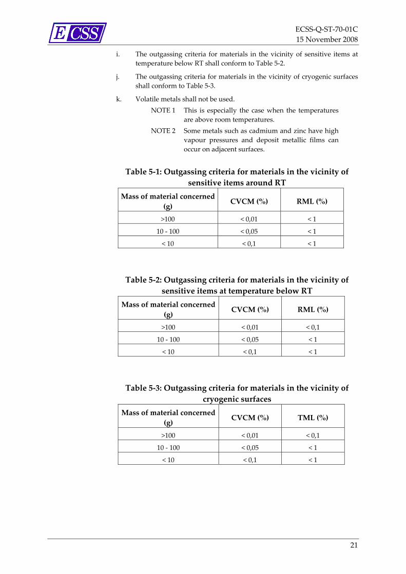
g. When contamination sensitive items are involved or for materials in the vicinity of cryogenic surfaces, more stringent requirements shall apply.
NOTE Those more stringent requirements are specified in clauses 5.2.1.2h to 5.2.1.2j.
h. The outgassing criteria for materials in the vicinity of sensitive items around RT shall conform to Table 5‐1.
20
ECSS‐Q‐ST‐70‐01C 15 November 2008
i. The outgassing criteria for materials in the vicinity of sensitive items at temperature below RT shall conform to Table 5‐2.
j. The outgassing criteria for materials in the vicinity of cryogenic surfaces shall conform to Table 5‐3.
k. Volatile metals shall not be used. NOTE 1 This is especially the case when the temperatures
are above room temperatures. NOTE 2 Some metals such as cadmium and zinc have high
vapour pressures and deposit metallic films can occur on adjacent surfaces.
Table 5‐1: Outgassing criteria for materials in the vicinity of sensitive items around RT
Mass of material concerned (g) CVCM (%) RML (%)
>100 < 0,01 < 1
10 ‐ 100 < 0,05 < 1
< 10 < 0,1 < 1
Table 5‐2: Outgassing criteria for materials in the vicinity of sensitive items at temperature below RT
Mass of material concerned (g) CVCM (%) RML (%)
>100 < 0,01 < 0,1
10 ‐ 100 < 0,05 < 1
< 10 < 0,1 < 1
Table 5‐3: Outgassing criteria for materials in the vicinity of cryogenic surfaces
Mass of material concerned (g) CVCM (%) TML (%)
>100 < 0,01 < 0,1
10 ‐ 100 < 0,05 < 1
< 10 < 0,1 < 1
21

ECSS‐Q‐ST‐70‐01C 15 November 2008
5.2.2 MAIT
5.2.2.1 Manufacturing a. Personnel involved in the manufacturing of sensitive items shall be
trained with respect to the cleanliness control policy.
b. All elements manufactured in non‐controlled areas or under non‐clean conditions shall be the object of a cleaning process until the cleanliness requirements are met, before they are packaged for delivery.
c. Cleaning and packaging operations for all elements shall be processed according to procedures approved by the customer for the specific application/product.
d. Elements that can be cleaned after manufacturing shall be cleaned till the cleanliness requirements are met.
e. For elements that cannot be cleaned after manufacturing, then manufacturing and assembling areas shall meet the cleanliness level requirements specification.
f. The conformity of the manufacturing facilities shall be verified during MRR or TRR.
g. An audit of the manufacturing facilities shall be performed according to ECSS‐Q‐ST‐10 clause 5.2.3 criteria.
h. An audits shall be held after problems have already occurred or as part of a plan to establish if facilities and personnel are adequate.
5.2.2.2 Assembly and Integration a. Involved personnel shall be trained with respect to the cleanliness policy.
b. Critical and sensitive elements shall only be exposed when necessary. NOTE Exposition of sensitive and critical elements during
optical calibration or alignment cannot be avoided.
c. When an exposure of sensitive and critical elements cannot be avoided, the exposure time and conditions shall be recorded.
d. A set of assembly tools and equipment for assembly and integration shall be used and maintained in clean conditions.
e. Procedures for assembly and integration shall be established for critical item assembly.
f. For the selection of the cleanroom, the allocated contamination budget and the duration of the integration shall be known.
NOTE The correlation between the airborne contamination and the particle fallout for normal cleanrooms is basically known (see clause 5.3.1), and so a rough estimate can be made of the type of cleanroom required. A practical contamination level for the cleanroom can be measured with representative activities and a representative number of operators. The expected contamination levels depend on the
22

ECSS‐Q‐ST‐70‐01C 15 November 2008
type of protection applied to critical hardware (e.g. covers, shields and purging).
g. The conformity of the facilities shall be verified during MRR or TRR.
h. An audit of the integration facilities shall be performed according to ECSS‐Q‐ST‐10 clause 5.2.3 criteria.
i. An audit shall be held after problems have already occurred or as part of a plan to establish if facilities and personnel are adequate.
5.2.2.3 Testing a. Involved personnel shall be trained with respect to the cleanliness policy.
b. For test centres, ECSS‐Q‐ST‐20‐07 shall apply.
c. The conformity of the facilities shall be verified during MRR or TRR.
d. An audit of the test facilities shall be performed according to ECSS‐Q‐ST‐10 clause 5.2.3 criteria.
e. An audit shall be held after problems have already occurred or as part of a plan to establish if facilities and personnel are adequate.
5.2.3 pre-launch and launch
5.2.3.1 General a. Personnel involved in pre‐launch activities shall be trained with respect
to the cleanliness policy.
b. The space system shall be shipped to the launch base under clean conditions as defined in the CRS and controlled by the C&CCP.
c. The potential contamination during launch preparation shall be also controlled.
NOTE This can be done through the C&CCP or through specific launch base procedures approved by the project.
d. Contamination during launch shall be controlled through preventive actions and specific design provisions.
NOTE Preventive actions can consist of cleaning and purging of the fairing. Specific design provisions can consist of shields controlling the depressurization.
5.2.3.2 Specific design provisions a. Launcher parts, shall be clean in order to avoid contamination of the
clean items of the space system. NOTE Launcher parts can be fairings and mechanical
systems for double or multiple launches.
23

ECSS‐Q‐ST‐70‐01C 15 November 2008
b. The materials of the hardware in the vicinity of the space system shall meet the same outgassing and surface‐cleanliness requirements as the space system itself.
c. The building environment in which the spacecraft is put inside the fairing shall be compatible with the spacecraft characteristics.
NOTE 1 Specific spacecraft design provisions can be protection mechanisms used to limit the launch contaminants, especially the “unknown” figure of particle transfer during launch.
NOTE 2 A second design aspect is the location of the contamination‐sensitive items with respect to the position of thrusters and of pyrotechnics or other contamination sources.
NOTE 3 The reflection by atmospheric molecules (i.e. atmospheric scattering) or by outgassing molecules (i.e. self‐scattering) can take place and some form of modelling is of interest.
5.2.4 Mission a. External contamination control during mission shall be done through
preventive actions, specific design provisions and operations. NOTE 1 Preventive actions include materials selection (see
clause 5.5.3 in ECSS‐Q‐ST‐70‐02), bakeout (see clause 5.4.3.2) and purging (see clause 5.4.3.3).
NOTE 2 Specific design provisions include the implementation of heaters for decontamination of sensitive surfaces, of shutters and baffles.
NOTE 3 Operations include shielding during dumping, thrusters firing or venting,, decontamination of sensitive surfaces through exposure to the Sun.
b. Fluids that can emerge to the exterior by leakage or intentional use of valves shall be considered in the design and operational requirements of system and equipment hardware.
c. A specific analysis shall be performed to ensure an optimum level of detection, location and isolation techniques.
NOTE These fluids are originating from thermal, environmental or life support systems or subsystems or released due to crew activities (nutrients, wastes), during maintenance and repair and from experiments or payloads as well as the propellant systems.
24

ECSS‐Q‐ST‐70‐01C 15 November 2008
5.3 Environments
5.3.1 Cleanrooms
5.3.1.1 Design of cleanroom: shell, entrances and anterooms
a. Cleanroom shell, floors, walls and ceiling shall be low shedding and the finish readily cleanable.
b. The covering floor shall consist of one piece or, if this is not feasible, shall have a minimum number of joints.
c. The floor shall be resistant to withstand wear by personnel and operations within the room.
d. The room shall be designed such that only one door or entrance can be opened at one time, except in case of emergency.
e. Entrances shall provide an air lock to allow a maintained pressurisation of the area.
f. Anterooms shall be equipped for the changing of clothes and the storage of clothing, personal belongings and cleaning equipment.
5.3.1.2 Air supply a. Air supply and filtration equipment shall have the capacity to filter all
new and recirculated air entering the room to guarantee the defined ISO class.
b. Air conditioning equipment for prefiltering (particular and molecular), cooling, heating, humidification and dehumidification of the cleanroom air supply shall be supplied to guarantee the environmental conditions.
NOTE See clauses 5.3.1.8, 5.3.1.9, 5.3.1.10 and 5.3.1.11.
c. In laminar flow cleanrooms, the air flow velocity through the cross section of the room shall be maintained at 27 m/min with a uniformity within ± 20 % throughout the undisturbed room.
d. Airflow patterns shall be uniform with minimum turbulence.
5.3.1.3 Filters a. In laminar flow cleanrooms, (HEPA) filters shall cover either one entire
wall or the entire ceiling, except when diffusion ceiling or wall systems are used or when built‐in benches are included in the incoming air end of the room.
b. Monitoring shall be done and any work with highly sensitive equipment shall not be performed before the defined ISO class for the hardware has been reached. as specified in the C&CCP for the following situations: 1. after the installation of new filters, 2. after “at rest “ period, 3. after stand by period.
25
ECSS‐Q‐ST‐70‐01C 15 November 2008
NOTE Due to the transitory pressure gradients, contamination previously trapped by HEPA filters, together with a reduction in the operating life of the filters themselves can be released.
c. The air flow inside cleanrooms and independent HEPA filtering systems shall be maintained during “at‐rest” periods, except for the maintenance operations.
NOTE 1 For example, during filters replacement. NOTE 2 Independent HEPA filtering systems can be like
those used for the laminar flow tents and benches. NOTE 3 This is to avoid the risk of redistribution of
particles at restart of the flow. NOTE 4 Exception can be made for independent HEPA
filtering systems that can work with a reduced air flow rate during stand‐by periods.
d. In cases where a uniform and controlled molecular environment is required, the filtering system shall be equipped with additional charcoal filters positioned before the HEPA filters.
e. When charcoals filters are used, the initial charge shall be assessed on installation and analysed regularly.
NOTE It can be useful to evaluate the charge in contaminants of the filtering system which can release its charge in contaminants trapped. in order to be able to monitor the evolution and when a failure occurs.
5.3.1.4 Particle levels and cleanroom classification a. Any airborne controlled environment shall be classified according to ISO
14644‐1:1999. NOTE 1 The number of particles per m3 as a function of the
diameter from 0,1 μm to 5 μm as classes is reported in Figure 5‐1 (derived from ISO 14644‐1:1999). This classification depends upon the ideal number‐size distribution and is given graphically in Figure 5‐1.
NOTE 2 Table 5‐4 presents selected airborne particulate cleanliness classes and the corresponding particle concentrations for particles equal to and larger than the considered sizes shown.
NOTE 3 The maximum permitted concentration of particles, Cn, for each considered particle size, D, is determined from the equation:
Cn=10N∙(0,1/D)2.08
where:
Cn is the maximum permitted concentration (in particles per cubic metre of air) of airborne particles that are equal to or
26
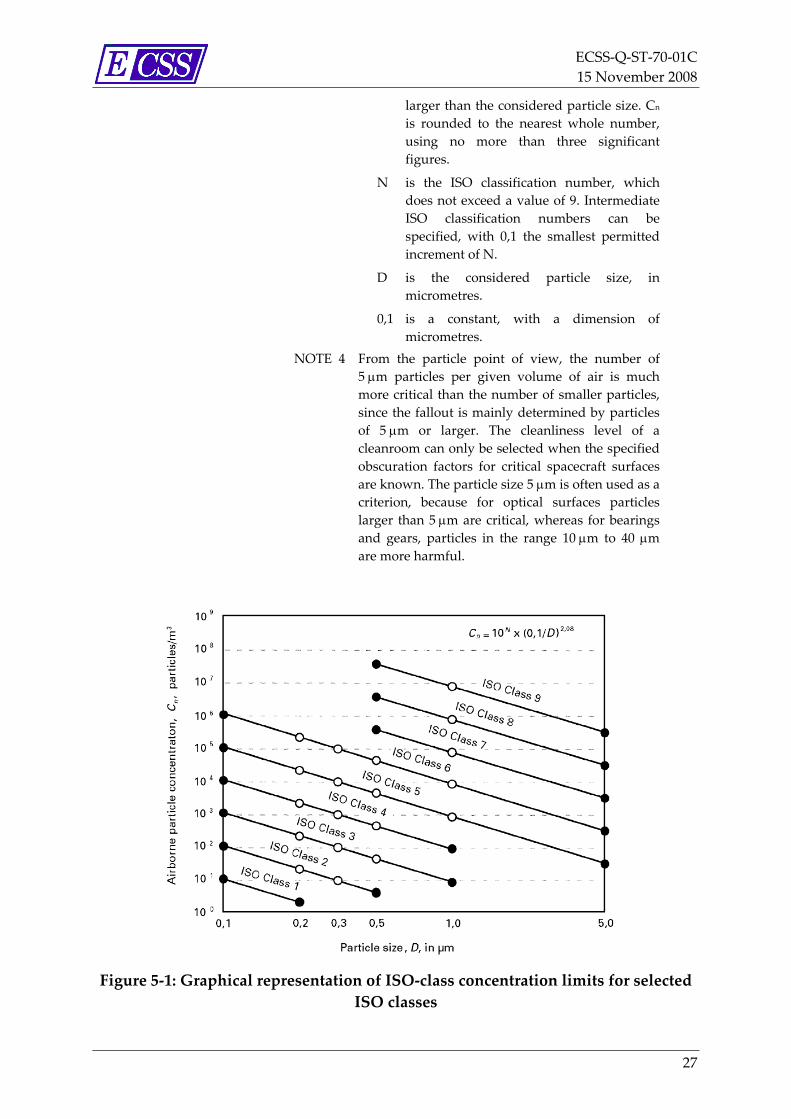
ECSS‐Q‐ST‐70‐01C 15 November 2008
larger than the considered particle size. Cn is rounded to the nearest whole number, using no more than three significant figures.
N is the ISO classification number, which does not exceed a value of 9. Intermediate ISO classification numbers can be specified, with 0,1 the smallest permitted increment of N.
D is the considered particle size, in micrometres.
0,1 is a constant, with a dimension of micrometres.
NOTE 4 From the particle point of view, the number of 5 μm particles per given volume of air is much more critical than the number of smaller particles, since the fallout is mainly determined by particles of 5 μm or larger. The cleanliness level of a cleanroom can only be selected when the specified obscuration factors for critical spacecraft surfaces are known. The particle size 5 μm is often used as a criterion, because for optical surfaces particles larger than 5 μm are critical, whereas for bearings and gears, particles in the range 10 μm to 40 μm are more harmful.
Figure 5‐1: Graphical representation of ISO‐class concentration limits for selected ISO classes
27

ECSS‐Q‐ST‐70‐01C 15 November 2008
Table 5‐4: Selected airborne particulate cleanliness classes for cleanrooms and other controlled environment
5.3.1.5 Monitoring of cleanroom air a. The cleanroom air shall be monitored with dust counters.
b. Accuracy and repeatability of instrumentation shall be demonstrated.
c. Particle counts shall be acquired continuously for the monitoring of the cleanroom itself.
d. A minimum of two particles counters shall be installed, one close to the air inlet and one or more according to the surface extent of the cleanroom by using the following law:
N = log10 (S)
where N is the number of particle counters and S is the surface of the cleanroom in m².
NOTE The purpose of the location close to the air inlet is to check the quality of the in‐coming air.
e. For any sensitive hardware, sampling frequency and locations shall be defined in the C&CCP.
f. Monitoring techniques and routines shall be established to meet the requirements of a specific category of cleanroom or clean work station.
g. Sampling air volume for the cleanroom classification shall be established on the basis of the ISO 14644‐1, Annex B.
h. Compliance with particles concentration limits shall be done with a frequency as specified per ISO 14644‐2, Clause 4.2.1.
i. Determining the extent to which particles are deposited on surfaces shall be achieved.
28

ECSS‐Q‐ST‐70‐01C 15 November 2008
NOTE This can be done through the exposure of test surfaces or samples to the environment and counting the settled particles by appropriate methods.
j. Air monitoring of class ISO 8 or better shall be achieved by means of light scattering equipment.
k. Tests shall be performed to determine if leaks exceed the specified limits, according to the filter characteristics: 1. in the filter media themselves, 2. in the bond between filter media and the interior of the filter
frame, 3. between filter frame gasket and filter bank supporting frames, 4. between supporting frames and walls or ceilings.
l. The cleanrooms shall have a monitoring function of the contamination levels and the environmental parameters.
m. The cleanroom shall have an alarm function activated when warning levels are exceeded.
NOTE 1 Those warning levels are usually defined well below the out of specification limits in order to prevent their exceedence.
NOTE 2 Environmental parameters are temperature, relative humidity and differential pressure.
n. Planned corrective actions shall be initiated to re‐establish the nominal conditions in the shortest possible time and to prevent recurrence.
5.3.1.6 Surface particulate levels a. For a preliminary budget only, i.e. for SRR, the correlation between the
airborne and PFO shall be established on the basis of the Table 5‐5.
b. The budget, during the different project phases, shall be consolidated with in‐situ measurements.
Table 5‐5: Correlation airborne and PFO for cleanrooms
ISO class PFO
(mm2/m2/24 h) 5 2,0
6 10
7 52
8 275 NOTE The data contained in this table are based on several
measurements performed in different cleanrooms. They are represented by this approximate law: PFO = 0,069 10(0,72M‐2.16) where M is the ISO class (e.g. ISO class 5)
29
ECSS‐Q‐ST‐70‐01C 15 November 2008
5.3.1.7 Surface molecular levels a. Molecular deposits shall be monitored by exposure witness plates.
b. For actual measurements at least, two different witness plates shall be placed in two different locations.
c. For each location, one of the two witness plates shall be analyzed at least once month.
d. The other witness plate is cumulative and shall be analyzed after more than one month.
e. These locations shall be selected in order to measure molecules in significant points of the environment with at least one representative of the empty cleanroom.
f. Molecular contamination in controlled environments shall not exceed 0,5 × 10‐7 g/cm2 during a continuous period of one week.
NOTE 1 In case of contamination sensitive equipment, a lower level can be required, based on the contamination budget (including exposure time).
NOTE 2 In a normal cleanroom (without charcoal filters) levels can be achieved that are 10 to 100 times better.
g. For those hardware items where the accumulation from the air becomes a major issue, the use of charcoal filters as molecular contamination trap should be considered.
NOTE Example of such a hardware are coated mirrors.
5.3.1.8 Temperature control a. Cleanroom temperature shall be maintained at nominally 22 °C ± 3 °C
and shall be monitored continuously. NOTE Temperature variations of ± 3 °C at the control point
are acceptable for most operations, but more stringent conditions can be imposed in case of critical operations.
b. The temperature distribution inside a cleanroom shall be controlled at representative locations for the hardware items.
NOTE 1 In order to ensure that a nominal temperature is achieved throughout the room. Automatic devices can be used for temperature monitoring.
NOTE 2 If items being worked on are extremely sensitive to temperature changes, automatic devices with a warning system that comes into operation when a temperature change occurs can be used.
5.3.1.9 Pressure control a. A positive pressure differential shall be maintained between the
cleanroom and the outside.
30
ECSS‐Q‐ST‐70‐01C 15 November 2008
b. Pressure shall decrease successively between the cleanroom, entrance lock, anteroom and the surroundings.
c. The positive minimum pressure delta to be maintained shall be: 1. Between cleanroom and surrounding area; 1,2 mm H2O (12 Pa). 2. Between cleanroom and entrance lock; 0,5 mm H2O (5 Pa).
d. Pressure in all areas shall be monitored continuously NOTE In order to take timely corrective actions in case of a
pressure drop.
5.3.1.10 Humidity control a. The relative humidity shall be maintained at (55 ± 10) % for general
applications and shall be monitored continuously. NOTE Humidity becomes detrimental due to electrostatic
charging or surface corrosion (see Annex L).
5.3.1.11 Bioburden control a. ECSS‐Q‐ST‐70‐58 shall apply for the control of bioburden in cleanroom.
5.3.1.12 Maintenance and cleaning a. All maintenance and cleaning activities shall be reported in a logbook.
b. A maintenance and cleaning procedure or document shall be available, along with a planning.
c. Maintenance shall comprise regular inspections of the cleanroom, its control facilities and its operating equipment, including calibration of all inspection and monitoring devices as specified in ECSS‐Q‐ST‐20.
d. Inspections of the cleanroom shall be performed at specified frequency, depending on the ISO class.
NOTE Those inspections assess the quality of the clean facility and describe any contamination production or events that are detrimental to the cleanroom cleanliness (e.g. repairs, system modifications, replacements, filter resistance measurements, leak checks or air speed measurements).
e. The frequency of inspections and cleaning processes for a cleanroom shall be optimized.
NOTE The inspections and cleaning can themselves be the source of contamination.
f. Data shall be recorded in a logbook.
g. Regular cleaning shall be performed depending on the ISO class.
h. Procedures shall cover the cleaning of the cleanroom including personnel air lock; equipment air lock, walls, floors, furniture, crane lifting devices and GSE.
31
ECSS‐Q‐ST‐70‐01C 15 November 2008
i. The cleanliness after the cleaning operations shall be verified by inspection by means of UV or high intensity white light.
j. Any personnel involved in cleaning operations shall be trained and informed about the criticality of a cleaning operation within a cleanroom.
k. Cleaning tools, solvents and gases that are used for cleaning purposes shall be chosen not to have a detrimental effect on the hardware within the cleanroom.
NOTE Cleanroom air of better than class ISO 8 is transported in a close loop. Since only a limited percentage of fresh air is fed to the loop, excessive use of solvents offgassing into the air, even if not flammable or toxic, can cause health problems.
l. When the level of contamination exceeds the cleanliness requirements specification, corrective actions shall be taken.
NOTE The decision as to whether or not to clean depends on the integration flow of the unit within the cleanroom.
5.3.1.13 Access control requirements a. An access control system shall be available independently for
cleanrooms, storage area and equipment airlock.
b. The access to the areas shall be controlled by a permanently operating access control or door lock system.
c. Only authorized personnel shall have access to the cleanroom. NOTE Access control areas have a security lock at the
entrance.
d. Visitors and personnel without a work order shall not be allowed to enter the cleanroom.
e. Visitors working in the cleanroom, shall: 1. wear the complete clothing, 2. be identifiable, 3. be instructed about the behaviour in a cleanroom.
f. Racks or cabinets for street clothing shall be separated from those used for cleanroom clothing.
g. Barriers or similar means separating clean and not clean zones inside the airlock shall be placed.
NOTE Similar means can be tacky mats.
h. Lint‐free clothing shall be available and worn by all personnel within cleanroom area.
i. Head covers or other garments shall be used as required to trap loose particles of hair or skin flakes.
j. Gloves, approved finger cots, tweezers or clean handling methods and equipment shall be used while working with or handling sensitive parts.
32

ECSS‐Q‐ST‐70‐01C 15 November 2008
NOTE This is to avoid contamination of those parts by loose skin or natural skin oils.
k. All equipment shall be cleaned by dusting, vacuum suction, washing, or other means suited to the equipment involved before being brought into the area.
l. Exhaust systems for grinding, welding or soldering, machining or related operations shall be installed.
m. Actions related to equipments items with cooling fans shall be identified and mitigated in order to avoid contamination of critical hardware.
NOTE Equipments items with cooling fans are potential contamination sources.
n. Personnel shall be instructed about the behaviour in a cleanroom.
o. Personnel movements to and from the cleanroom shall be kept to a minimum.
p. Smoking, eating and drinking shall not be permitted in the cleanroom, including the entering areas and air locks.
q. Local cleanroom instructions shall specify the amount of protective clothing to be worn and shall reduce to the minimum the contaminant transfer.
r. If air showers are used, only suitably clothed personnel shall be allowed to enter.
s. Paper, pencils or erasers shall be kept outside the clean facilities. Only special non‐shedding papers and ball‐points shall be used.
t. Cosmetics and medicaments that can produce contamination shall not be used by any personnel.
NOTE In particular, eye make‐up, rouge, face powder and hair spray.
u. Fingernail polish shall not be permitted in the area.
v. Before entering a cleanroom, hand lotions, creams or soap containing lanolin to tighten skin particles shall be used.
w. Contact of hands with solvents shall be avoided. NOTE Many solvents remove natural oils and cause
excessive skin peeling or flaking.
5.3.2 Vacuum facilities a. Procedures shall be available for:
1. The cleaning of the test facilities. NOTE Handling of solvents and running a bakeout
2. The pump‐down and recovery sequences with respect to contamination redistribution.
NOTE A good solution, for chamber repressurization, is to add an HEPA filter to the repressurization piping
33
ECSS‐Q‐ST‐70‐01C 15 November 2008
and to collect the air for repressurization in a clean area (preferably ISO class 5).
3. The regeneration of sorption pumps. NOTE Sorption pumps can be e.g. cryopumps, zeolites, or
charcoal. 4. The cleaning of cold trap.
b. For a test in a vacuum facility, it shall be ensured that the item under test does not pose any risk of contamination of the facility.
c. An approved declared material list (DML) of the hardware under test, including the test adapter and all connections shall be provided.
NOTE Including, for example mechanical and electrical connexions.
d. A pre‐test shall be performed to prove the cleanliness of the facility.
e. During the pre‐test, test equipment and cabling shall be included in the facility.
f. During the pre‐test, pump down and repressurization sequences shall be similar to the actual test.
NOTE In typical “clean” vacuum systems, a sensor (or a critical surface) is not contaminated by more than 1 × 10 g/cm during a blank test of 24 hours duration. The sensor is normally at room temperature, but, more stringent requirements can be imposed, depending upon the budget allocation for the equipment. In fact, for sensitive equipment, 0,3
‐7 2
× 10 g/cm , 24 hours (or 0,5 ‐7 2 × 10 g/cm , week) for a blank test is often specified.
‐7 2
5.3.3 Other facilities a. The CRS and the C&CCP shall address the cleanliness and contamination
control policy for any other facilities such as anechoic chamber, EMC chamber.
5.4 Activities
5.4.1 Cleaning of hardware
5.4.1.1 General aspects a. Cleaning shall be performed in order to ensure that the required
cleanliness levels, expected in the contamination budget, and the final product cleanliness level are achieved.
NOTE In order to meet the BOL requirements, a final cleaning of external surfaces can take place just
34

ECSS‐Q‐ST‐70‐01C 15 November 2008
before the entry of the space system into the fairing, or even just before closing the fairing.
b. The choice of the cleaning method shall be determined by the following criteria: 1. The type of contaminants to be removed. 2. The physical or chemical nature of the item to be cleaned. 3. The actual on ground phase.
NOTE 1 Examples are provided in Annex M for removal of both particulate and molecular contamination.
NOTE 2 The cleaning of some parts is particularly important during the course of manufacture or before processing (e.g. prior to bonding, painting, vacuum, coating, welding and soldering).
NOTE 3 Any detrimental effect of cleaning is evaluated as well as the order of the defined cleaning methods.
NOTE 4 For those items that are too delicate to withstand cleaning, preventive contamination control is of the utmost importance.
c. The cleaning procedures shall be mentioned in the process specification.
d. The cleaning procedures shall be validated by tests on representative samples, or by experience from previous and similar projects, in which they were validated.
5.4.1.2 Cleaning tools
5.4.1.2.1 Cleaning aids
a. Cleaning aids shall not increase the contaminant levels of the items to be cleaned.
b. Aids, such as wipe tissues, papers, cloths, brushes and foams shall be non‐fluffing, lint free and dust free.
c. Damage to surfaces as scratches shall be minimal.
d. NVR of cleaning wipe materials shall be less than 0,01g/m2 for wiping extremely clean surfaces when extracted with IPA.
NOTE Different examples of NVR for common tissues are given in Annex K.
e. When wipe materials are selected for cleaning, measurements shall be taken to determine their contaminant content.
f. All wipe materials should be precleaned to achieve the specified level of cleanliness.
NOTE Extraction by solvents is the way for precleaning the wipes materials.
35
ECSS‐Q‐ST‐70‐01C 15 November 2008
5.4.1.2.2 Cleaning fluids
a. The cleaning solvent shall be selected on the basis of its compatibility with the material or item to be cleaned and its efficiency in removing contaminants.
NOTE A compatibility table between materials and solvents is given in Annex I.
b. Toxicity and flammability of solvents shall be evaluated (see MIL‐HDBK‐406) and be compliant to the local law.
c. For precision cleaning, solvents of high purity shall be used (see Annex J).
d. The cleaning gas shall be free of oil and filtered to remove particulate contamination according to the needs.
5.4.2 Cleanliness monitoring of space hardware
5.4.2.1 General a. Particulate and molecular contamination shall be monitored during all
the on ground phases. NOTE For specific missions, particulate and molecular
contamination can be monitored during launch and in space.
5.4.2.2 Particulate contamination monitoring a. Particulate contamination shall be monitored through visual inspection
and shall be quantified through optical monitoring of surfaces.
b. Surfaces shall be examined with the naked eye or with the aid of magnification devices under grazing incident light level of, at least, 1000 lux.
NOTE 1 Different kinds of lights can be used: portable diving light or “white light” is often used for standard inspection. In addition, ultra‐violet lamp or “black light” (365 nm) can be used for inspection of organic residues and dust particles as it increases their visibility.
NOTE 2 Typical methods are the measurement of transmission or reflection loss and nephelometry (i.e. scattering of light). These methods can be used for all types of contaminants, both organic and inorganic. Photographic determination of dust particles on surfaces is also possible, as is automatic counting.
NOTE 3 There are commercially available instruments (e.g. PFO photometers) that automatically measure the particle fallout level on sensor plates, exposed during phases of interest.
NOTE 4 The method for measuring of the PFO level is described in the ECSS‐Q‐ST‐70‐50 but another
36

ECSS‐Q‐ST‐70‐01C 15 November 2008
method for the determination of the particle contamination can also be microscopic counting (manual or with the aid of an imaging recognition software).
NOTE 5 Extraction methods can be performed by:
• tape lift, using sticky tapes (according to ECSS‐Q‐ST‐70‐50);
• blowing and suction of air;
• washing of the surface of interest and counting the particles in the washing fluid either directly using a commercial instrument, or on a filter after filtration of the liquid.
NOTE 6 The “visibly clean” level roughly corresponds to an obscuration factor smaller than 300 mm2/m2.
c. When using ultra‐violet or “black light” (365 nm) lamps for inspection of organic residues, the induced thermal and health effects shall be assessed.
5.4.2.3 Molecular contamination monitoring a. Molecular contamination shall be monitored through visual inspection
and quantitative methods directly on the surface (including witnesses) or indirectly after transfer of contaminants.
NOTE 1 Surfaces can be examined by the same visual inspection methods as for particulate contamination. Experience with Micro‐VCM tests has shown that, generally, levels of organic contamination above 1 × 10‐6 g/cm2 can already be visible to the naked eye. By wet wiping of a portion of the surface or after evaporation of a droplet of a substrate compatible solvent, a contamination can be revealed by contrast.
NOTE 2 A surface of a known area is wiped with a clean tissue, the tissue is subjected to extraction with chloroform of spectral grade, and the residue of the chloroform is analysed by infrared techniques in accordance with ECSS‐Q‐ST‐70‐05. This method, applied to a wiped area of 100 cm2, permits detection of organic contamination levels down to 3 10‐9 g/cm2. The results of this method depend very much on the surface roughness, on the type of tissue and on the solvent used. Particular attention is paid to the compatibility between solvent and surface.
NOTE 3 A surface of a known area is rinsed with a solvent and the residue is weighed after evaporation according to ASTM‐E1235M‐95.. The accuracy and detection limit of this method depend greatly upon the sensitivity of the balance, the substrate water
37
ECSS‐Q‐ST‐70‐01C 15 November 2008
absorption, the washing efficiency and the solvent background. The NVR measurement is expressed in mass per unit area and the residue can be used for further analyses). Direct measurements can be made in situ using quartz crystal microbalances (QCM).
NOTE 4 Further analyses can be performed to characterize molecular contamination (e.g. gas chromatography, mass spectrometry, ultra‐violet degradation, SEM).
5.4.2.4 Contamination monitoring in vacuum facility a. Monitoring of molecular and particulate contaminants in vacuum
facilities shall be achieved using the witness or the QCM method, or a combination of both.
b. When using the witness method the temperature and location of witnesses shall be representative of the item.
NOTE 1 Witnesses (for both molecular and particulate contamination) can be placed on or near suspect places for a specified time and then subjected to one of the standard analyses.
NOTE 2 A QCM can be used to detect contamination levels down to 1 × 10‐9 g/cm2, and to measure condensation rates. Such QCMs can operate down to liquid nitrogen temperatures.
NOTE 3 A mass spectrometer is not sufficient to monitor the condensable contaminants but in combination with a QCM, it can help describing the different condensed species during a controlled re‐evaporation from the QCM.
NOTE 4 A cryopanel can be used to collect all molecular contaminants for further analyses.
5.4.2.5 Contamination monitoring during launch a. QCM shall be used to monitor molecular contamination.
NOTE 1 The QCMs can be installed on the launcher and the measuring time is limited to a few minutes; if the QCMs are installed on the space system, the measurements can continue during mission.
NOTE 2 The temperature of QCM can be either uncontrolled or kept constant.
NOTE 3 For the interpretation, the thermal fluxes and the solar fluxes can affect the QCM readings and corrections can then be necessary.
NOTE 4 For the monitoring of particles during launch, no specific method is established at present time.
38

ECSS‐Q‐ST‐70‐01C 15 November 2008
5.4.2.6 Contamination monitoring in space a. Contamination of external surfaces should be monitored.
NOTE 1 particulate contamination can be measured by light scattering (e.g. using the Sun or a laser as the a light source) or using QCMs with a crystal having a surface to which particles stick.
NOTE 2 Molecular contamination can be measured using QCM located near a sensitive item and maintained at the same temperature as the item or using a mass spectrometer.
NOTE 3 Measurements of contamination in space are not often made because the policy of cleanliness control is based upon the basic principle of achieving the lowest possible contamination levels with existing knowledge and within the allocated financial budgets. However, it is advisable to implement an “in space contamination monitoring” as part of the spacecraft housekeeping. When appropriate sensor elements are applied it is possible to predict design life‐times at system, subsystem, component or equipment levels.
b. For internal environments monitoring of particulate, molecular and microbiological contamination shall be assessed.
5.4.3 Cleanliness verification
5.4.3.1 General a. The cleanliness verification activities shall be specified in the C&CCP.
b. The cleanliness verification shall include all the activities intended to ensure that the actual cleanliness conditions of the space system, the cleanrooms or the vacuum chambers conform to the applicable standards or the applicable CRS (specific to a certain project).
c. The cleanliness verification shall make use of recognized methods for the determination or the monitoring of the contamination levels.
d. The cleanliness verification of cleanrooms shall also include the verification of the environmental parameters such as temperature, relative humidity and the overpressure.
e. The cleanliness verification shall take place under one or more of the following conditions: 1. At predetermined intervals, independently of the current activity,
to confirm the efficiency of the established cleanliness control measures.
2. After the occurrence of an incident or anomaly that can have influenced the cleanliness conditions of the space system or cleanroom.
39

ECSS‐Q‐ST‐70‐01C 15 November 2008
3. Before the beginning of the ground (e.g. test campaign) or launch activities, to confirm that the facilities and cleanrooms are conform to the relevant C&CCP.
4. Before and after a test in a vacuum chamber.
f. A cleanliness declaration of conformity shall be delivered for space hardware.
g. In case of nonconformance of an item, corrective actions shall be applied and ECSS‐Q‐ST‐10‐09 shall apply.
5.4.3.2 Bakeout a. When contamination predictions exceed the allocated contamination
budget, a bakeout shall be performed. NOTE 1 The aim of the bakeout is:
• To improve the outgassing behaviour of a material/item.
• To reduce the level of surface contamination collected during processing or testing.
NOTE 2 Typical materials on which bakeout can be applied are: • Harness • MLI • Carbon and glass fibre components • Glued, coated or potted materials.
b. The bakeout conditions (temperature, time, pressure) shall not have a detrimental effect on the functionality of the material/item under bakeout.
NOTE It is more efficient to perform a bakeout at the lowest possible product level to allow reaching higher bakeout temperature (i.e. to avoid temperature constraints at higher assembly level)
c. The effectiveness of the bakeout shall be monitored by means of one the following methods: 1. By using a QCM.
NOTE Eventually also a Residual Gas Analysis (RGA), as already described in NOTE 3 of 5.4.2.3 “Molecular contamination monitoring”.
2. By outgassing testing the material/item before and after the bakeout.
NOTE 1 The second method is in general only practical for materials and items containing a limited number of materials.
NOTE 2 Other analytical methods can be considered but their effectiveness is not yet be proven (e.g. in situ optical methods).
40

ECSS‐Q‐ST‐70‐01C 15 November 2008
d. Independently of the chosen method, success criteria shall be established and approved before starting the bakeout.
e. When the QCM monitoring or other in situ analytical methods are chosen, a “stopping” criterion” shall be defined.
NOTE This “stopping” criterion is also a way to determine if going further with the bakeout is worth or not. For instance, this criterion can be based on the change of the mass rate (i.e. on the second derivative of the QCM frequency).
f. When outgassing testing methods are chosen, a “verification criterion” shall be defined.
NOTE For instance, the “verification criterion” can be based on the reduction of the outgassing potential.
g. The different outgassing mechanisms shall be used in the elaboration of the stopping and verification criteria.
NOTE 1 Desorption and diffusion are examples of outgassing mechanisms).
NOTE 2 In case of outgassing testing after the bakeout, a certain time is necessary for reconditioning of the material/item to consider the diffusion phenomenon.
h. The background of the baking facility shall be determined before starting the bakeout.
NOTE This can be done by using a QCM or molecular witnesses. The use of QCM is preferred because it provides the background of the chamber in function of time whereas witness plates can only provide the integrated value.
i. Independently of any stopping and verification criteria, the minimum bakeout duration shall be 72 hours.
j. Baking time shall start when the material/item under baking has reached the predefined bakeout temperature.
5.4.3.3 Purging a. The purging shall be performed inside a cavity to maintain a constant
exchange of the gas present in the cavity. NOTE 1 This exchange depends on the entry flow rate of
the gas and the total surface leaks. NOTE 2 The aim of the purging is not only to protect the
critical hardware such as optics from contamination by injecting a non‐ionized high‐purity dry gas inside a cavity but also a way for decontamination (e.g. removal of water for dimensional stability of composite).
NOTE 3 The purging can be implemented at instrument or spacecraft level during functional and performance
41

ECSS‐Q‐ST‐70‐01C 15 November 2008
tests at ambient conditions, during repressurization after TB/TV and TV tests, during all the phases without activities and during storage, transport and pre‐launch phases up to the final close of the fairing. (In case of an aborted launch, purging can be not re‐installed).
b. The purity of the gas and the cleanliness of all the pipes shall be verified before the first use of the purging system.
c. Filtering systems (both for MOC and PAC) shall be provided before the gas comes into contact with the hardware.
d. The filtering capabilities shall be compatible with the relevant cleanliness requirements.
5.4.4 Packaging, containerization, transportation, storage
a. Provisions shall be taken for packaging, containerization, transportation and storage.
NOTE In order to maintain the cleanliness levels achieved at any point from initial precision cleaning to delivery to the launch site.
b. Cleanliness protection shall be provided prior to leaving the controlled areas, or whenever a storage period is planned.
c. The container for clean item shall maintain the cleanliness levels specified for the product.
d. Storage areas shall provide adequate protection to the package and the product for the intended storage period.
e. Transport and storage containers shall be made of low particle shedding materials that do not evolve contaminants.
f. Containers carrying sensitive items shall be pressurized with gaseous nitrogen.
NOTE Optical units and payloads are examples of sensitive units
g. Containers carrying sensitive items shall also have as rigorous cleaning schedule as the parts themselves.
h. It shall be ensured that containers used for transportation of clean parts do not transfer contamination from surface to surface within the cleanroom itself.
NOTE Witness plates can be placed inside containers.
i. When sensitive items are packaged, containers for long‐term storage or transportation, shall include provision for internal flushing with dry high‐purity nitrogen and over‐pressurization of 100 hPa minimum, except if units are put in sealed bags.
j. For long term storage of sensitive items, containers shall be equipped with an inlet valve and an outlet valve clearly identified.
42

ECSS‐Q‐ST‐70‐01C 15 November 2008
k. The design of the container shall facilitate easy cleaning and inspection of its surfaces, avoiding any kind of dirt traps.
l. Small clean parts shall be double bagged in airtight envelopes during storage or transportation outside controlled clean areas.
m. Bags for contamination‐sensitive items shall be flushed with dry nitrogen or dry clean air and then sealed.
n. Only approved materials that were procured as cleaned films shall be used.
o. Static sensitive items shall use metallized films.
p. Outer bags shall not enter controlled clean areas.
q. When used, desiccants shall be in bags that are clean and do not produce particulate contamination.
r. Desiccants and humidity indicators shall be placed in the external envelope.
s. Procedures shall be provided for packaging, containerization, transportation and storage.
43
ECSS‐Q‐ST‐70‐01C 15 November 2008
Annex A (normative) Cleanliness requirement specification
(CRS) - DRD
A.1 DRD identification
A.1.1 Requirement identification and source document The CRS is called by the ECSS‐Q‐ST‐70‐01, requirement 5.1.2.1a.
A.1.2 Purpose and objective The purpose of the cleanliness requirement specification (CRS) is to establish cleanliness and contamination levels to be achieved at different MAIT, launch and mission stages.
Based on system or subsystem contamination budget, a CRS is established and agreed by all parties involved.
The CRS defines and identifies the spacecraft items and the environmental areas that are sensitive to contamination; and describes the effects of contaminants on their performance.
Specifying the spacecraft performance requirements to be met is the responsibility of the customer. The spacecraft performances specification is a major input parameter to define the acceptable contamination levels.
The CRS provides the acceptable contamination levels for all on ground and in‐flight phases to guarantee that the mentioned spacecraft performances are met.
On ground surface cleanliness levels are also univocally defined. NOTE By using ISO 14644 or IEST‐STD‐CC1246D.
44
ECSS‐Q‐ST‐70‐01C 15 November 2008
A.2 Expected response
A.2.1 Scope and content
<1> Introduction a. The CRS shall give a general overview of the item to which the CRS
refers, describing sensitive items and contamination sources, in consideration of:
1. possible impacts of contaminants on their physical or functional characteristics;
2. possible effects of contamination on the performance;
3. their impact as potential sources of contamination.
b. The CRS shall specify the pressures (or other molecular fluxes) that can be reached in connection with voltage breakdown, arcing, corona discharges, multipaction, opening time of shutters and ejection time of covers.
<2> Environmental factors a. The CRS shall basically specify major on‐ground activities to be analysed
for their impact on contamination and the relevant on‐ground contamination environment.
NOTE Usually, the preparation of a flowchart, that can be added as appendix to the CRS, helps in the description (see Annex C).
b. The CRS shall specify the flight environmental factors (natural and induced) that affect the contamination phenomena, such as solar radiation, electron, proton and AO fluxes, together with the planned mission profile/duration.
c. The CRS shall specify sensitive item temperatures to be used for the analyses during ground and in‐flight operations.
NOTE The expected temperatures and temperature profiles of these items can be important for condensation and the residence times of the contaminants.
<3> Contaminants a. The CRS shall describe all possible contamination sources to be analysed
and the maximum acceptable emissions. NOTE For example: Materials outgassing, lubricants
escaping from bearings, wear particles from moving parts, terrestrial contaminants such as dust, plume contaminants from thrusters and engines, leaks from fuel systems and from hermetically sealed components, dumps and EVA, co‐passengers, fairing and equipment bay items of the launcher.
45

ECSS‐Q‐ST‐70‐01C 15 November 2008
b. The CRS shall specify the chemical nature of the contaminants listed under <3>a. with their vapour pressures or relevant condensation conditions.
c. The CRS shall specify the transport mechanisms of the potential contaminants from the sources under <3>a. to the contamination sensitive items or areas to be considered in the contamination analysis.
NOTE For example: direct flux, reflected flux, ambient scatter, self‐scatter and creeping.
d. The CRS shall specify the contamination environment to be applied for design.
NOTE For example, molecular column density, maximum molecular deposition on the sensitive items.
<4> Contamination budget a. The CRS shall specify all cleanliness requirements allocated to the major
integration and testing phases.
b. The CRS shall specify acceptable contamination levels of MOC and PAC for all on ground and in‐flight phases.
A.2.2 Special remarks None.
46

ECSS‐Q‐ST‐70‐01C 15 November 2008
Annex B (normative) Cleanliness and contamination control
plan (C&CCP) - DRD
B.1 DRD identification
B.1.1 Requirement identification and source document The C&CCP is called by the ECSS‐Q‐ST‐70‐01, requirement 5.1.2.2a.
B.1.2 Purpose and objective The purpose of the Cleanliness and contamination control plan (C&CCP) is to establish the data content requirements for the cleanliness and contamination control plan. This DRD does not define format, presentation or delivery requirements for the cleanliness and contamination control plan (C&CCP), which can vary depending on product level (i.e. equipment, subsystem, system), and specific contractual requirements.
A cleanliness and contamination control plan is prepared in order to set out the ways in which the required cleanliness levels are achieved and maintained during the life of the programme, from design to end‐of‐life.
As it is of fundamental importance for the space system’s performance, the C&CCP is established as early as possible in the programme, in order to properly address the design.
The C&CCP is prepared for all levels of configuration items defined in the project at the following levels:
• System
• Subsystem
• Equipment
The C&CCP is based on the requirements defined by the cleanliness requirements specification (CRS).
The supplier is responsible for this document.
The C&CCP is prepared in collaboration with experimenters and engineers.
47
ECSS‐Q‐ST‐70‐01C 15 November 2008
B.2 Expected response
B.2.1 Scope and content
<1> Introduction a. The C&CCP shall contain description of the purpose, objective, content
and the reason prompting its preparation.
<2> Applicable and reference documents a. The C&CCP shall list the applicable and reference documents to support
the generation of the document.
<3> Terms, definitions and abbreviated terms a. The C&CCP shall include any additional terms, definitions or
abbreviated terms used.
<4> Description of [insert item name a. The C&CCP shall give a general overview of the item to which the
C&CCP is refers.
b. The C&CCP shall describe sensitive items and contamination sources, listing those surfaces/items to be strictly controlled or protected from the cleanliness point of view due to: 1. The possible impacts of contaminants on their physical or
functional characteristics. 2. Their impact as potential sources of contamination.
<5> Cleanliness requirements
<5.1> Requirements in CRS
a. The C&CCP shall contain: a summary of cleanliness requirements, relevant for the system or hardware and eventual sub assemblies, as given in CRS or dedicated analysis.
NOTE Example of such requirements are MOC, PAC, and during the different phases on ground and in‐flight.
<5.2> Contamination budgets
a. The C&CCP shall l contain the allocation of contamination levels through the splitting of cleanliness requirements during the major integration and testing phases.
NOTE In case the outgassing contribution to the performance loss is large with respect to other contributions (mainly for sensitive instruments with tight requirements), more detailed modelling are performed.
48

ECSS‐Q‐ST‐70‐01C 15 November 2008
<5.3> Selection of materials and processes
a. The C&CCP shall define the requirements that have design impacts like PMP selection criteria (see ECSS‐Q‐ST‐70), venting, purging and thrusters’ locations, in accordance with the mission cleanliness and outgassing requirements and the outcome of the clauses 5.1 and 5.2.
<5.4> Mitigation and corrective actions
a. The C&CCP shall describe the measures for the coordination and resolution of cleanliness and contamination control issues among the parties involved in the project.
b. The C&CCP shall describe the corrective actions in terms of design, shielding, purging, bakeout in case the predictions are outside acceptance limits and in cases where corrective actions are necessary because of deviation from the original cleanliness policy.
NOTE In general, the organization of regular workshops dedicated to cleanliness and contamination control for a specific programme is a good practice.
<6> Environments and facilities a. The C&CCP shall contain a brief description of MAIT areas, their
classification, facility location and tools for contamination control.
b. References for internal procedures dedicated to area or facilities verification, control and maintenance shall be included.
c. The C&CCP shall contain a list (or brief description) of internal procedures for personnel training and rules to operate under contamination control conditions.
<7> MAIT activities
<7.1> Contamination prediction
a. The C&CCP shall detail the splitting of cleanliness prediction during MAIT phases, according to planned duration, environment class, type of operation, and dedicated provisions adopted.
b. The C&CCP shall list all phases where contamination can be expected and where the levels can exceed the allocated levels.
<7.2> Contamination control
a. The C&CCP shall describe selected methods, procedures and instruments to control contamination levels during MAIT activities on systems or equipment and relevant documentation; in particular: 1. Contamination monitoring methods and tools. 2. Inspection procedures and tools. 3. Verification of tools or hardware. 4. Dedicated cautions for critical AIV operations.
49
ECSS‐Q‐ST‐70‐01C 15 November 2008
<7.3> Cleaning and decontamination methods and tools
a. The C&CCP shall define the cleaning and decontamination methods, procedures and tools, also making reference to their applicability and eventual process parameters.
NOTE List of items and process parameters (e.g. for a bakeout: temperature, pressure and minimum durations, stop criteria are part of the information of this clause.
<7.4> Packaging, storage and transportation
a. The C&CCP shall describe the provisions for the transportation of critical items.
b. The C&CCP shall include: 1. A description of containers and packaging tools to be used during
hardware transportation. 2. The way they are stored. 3. The way they are handled. 4. The way they are monitored and cleaned.
<7.5> Contamination control flow
a. The C&CCP shall define: 1. the sampling plan for PAC and MOC, 2. cleaning operations (when planned), and 3. inspection points.
b. A cleanliness control flow chart shall be established, showing the stages at which specific cleanliness controls are undertaken, reported in an annex to the C&CCP.
<7.6> Responsibilities
a. Responsibility and authority shall be assigned for the implementation of the cleanliness and contamination control tasks.
b. The C&CCP shall describe responsibilities for: 1. Hardware inspections 2. Cleanrooms and facilities 3. Contamination monitoring (hardware).
<8> Forms a. The C&CCP shall define the forms that are used to document the
cleanliness and contamination control activities defined by the C&CCP.
b. As minimum, the following forms shall be defined: 1. PAC and MOC measurement report. 2. Cleanliness declaration of conformity (see ECSS‐Q‐ST‐20).
B.2.2 Special remarks None.
50
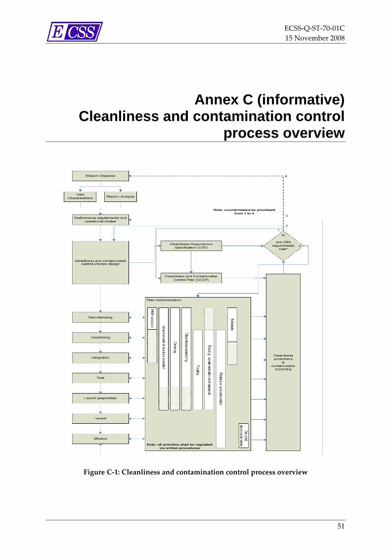
ECSS‐Q‐ST‐70‐01C 15 November 2008
Annex C (informative) Cleanliness and contamination control
process overview
Figure C‐1: Cleanliness and contamination control process overview
51

ECSS‐Q‐ST‐70‐01C 15 November 2008
Annex D (informative) Guidelines for general cleanliness and
contamination control
D.1 General Contamination control cannot be applied effectively without an understanding of the contaminant, the contaminant source and the detrimental effect that the contaminant has.
The known causes of failure and degraded performance of space elements attributed to contamination, including their sources, are given in this Standard.
When they are not known, tests and analyses can be performed (e.g. outgassing rates as a function of time, chemical composition of outgassing products, condensation rates or degradation as result of radiation).
The results of these tests and analyses can be used to calculate expected contamination levels and their subsequent effects if other relevant parameters are known.
Preventive cleanliness control is becoming more important as space systems become more sophisticated and mission durations are extended.
A problem frequently encountered in space technology is the lack of data enabling a good correlation between contaminant levels and mission performance requirements.
NOTE This kind of information can be available in the mass production areas of electronics and precision mechanical devices.
D.2 Contamination attributes
D.2.1 Typical contaminants and their sources
D.2.1.1. On ground
D.2.1.1.1 Particulate contaminants
Many particulate contaminants, such as dirt, sand, industrial fumes, can, to a large extent, be excluded from cleanrooms by filtering, and the space system
52

ECSS‐Q‐ST‐70‐01C 15 November 2008
can therefore be protected from them right up to the final preparation at the launch site.
Nevertheless, a considerable quantity of particulate contaminants are produced or released during all on ground phases of the space system, especially during testing activities.
NOTE Test facilities can be inside cleanrooms, but are basically not clean and can loosen particles and cause their redistribution
For example:
• Human sources
⎯ Hair cosmetics, dead human skin cells.
⎯ Fibres and lint from clothing, dust carried in on hair and clothes.
• MAIT
⎯ Chips and burrs from machined surfaces, solder and weld spatters.
⎯ Particles produced by wear or shedding, corrosion products, flakes from coatings and air filters.
⎯ Particles released from anechoic walls during the test.
⎯ Redistribution of particles during pumping down and repressurization of vacuum chambers, vibration test, transportation…
• Other sources
⎯ Bacteria, fungi, viruses and secondary products
D.2.1.1.2 Molecular contaminants
A considerable quantity of molecular contaminants are produced during all on ground phases of the space system, especially during testing activities.
NOTE Test facilities even if inside cleanrooms can be source of molecular contaminants the tested items.
Molecular contaminants can be found in different chemical phases, such as:
• Gases and vapours
⎯ Atmospheric gases, desorbed water, leaks in sealed units (e.g. freon, hydrazine, helium, neon and krypton)
⎯ Outgassing products from organic materials (e.g. monomers, plasticizers, additives and solvents)
⎯ Vapours from packaging materials and test facilities (e.g. vacuum pump oils)
⎯ Vapours from substances used in cleanrooms (e.g. plasticizers and cleaning fluids)
⎯ Secondary products coming from micro‐organisms.
• Liquids
⎯ Residues from cleaning agents
53

ECSS‐Q‐ST‐70‐01C 15 November 2008
⎯ Residues from adhesive masking tapes
⎯ Machine oils
⎯ Coolants
⎯ Lubricants
⎯ Solder fluxes
⎯ Cosmetics
⎯ Grease from human skin
⎯ Secondary products coming from micro‐organisms.
• Other contaminants
⎯ salt
⎯ acid
⎯ alkaline
⎯ corrosion products
⎯ oxidation products
⎯ finger prints
⎯ stains.
D.2.1.2. On launch
D.2.1.2.1 Particulate contamination
Launch contaminants can come from the acoustic noise and mechanical vibrations. The contamination source is then the space system itself and the fairing and structural parts during the first minutes of the launch.
Redistribution of the released particles can occur so that clean surfaces are covered by particles.
Also the co‐passengers can be the source of contamination in the case of multiple launches.
During the initial lift‐off, the pressure inside the fairing drops from atmospheric pressure to high vacuum within a few minutes, and the turbulence of the air can also redistribute the particles.
The contamination environment during launch can be severe and there is basically no control of the contamination during this period.
D.2.1.2.2 Molecular contamination
Next to the particle contamination, the molecular contamination is of importance, especially the outgassing of the materials, the release of contaminants by mechanisms, separation mechanisms, such as pyrotechnics and thermal knives, motors and thrusters.
The mechanism of molecular contamination is based upon outgassing under high vacuum; however, the period for which the space system is under high vacuum with other neighbouring hardware is very short.
54
ECSS‐Q‐ST‐70‐01C 15 November 2008
Predictions of the molecular transfer during this period can be estimated: this type of estimation can be made for co‐passengers when the outgassing requirements are less stringent than those for the space system of interest.
D.2.1.3. During mission
D.2.1.3.1 Overview
Even with a good contamination and cleanliness control policy, contamination during mission can not be completely avoided. Indeed, lessons learned from space systems returned to Earth after quite a long exposure to space e.g. LDEF, EURECA and solar arrays from the Hubble Space Telescope, indicated visible contamination especially near venting holes and at locations where photodeposition and photopolymerization occurred due to solar radiation, or where atomic oxygen has converted the volatile contaminants into non‐volatile contaminants.
Natural environments and induced environment are normally taken into consideration.
D.2.1.3.2 Natural environment
The natural environments described here affect the contaminants in the environment or on surfaces or affect the deposition of contaminants on surfaces.
Most of the natural environments mentioned in the following clauses are described in detail in ECSS‐E‐ST‐10‐04.
a. Vacuum and type of gases
The pressure of natural gases around the space system causes reflection of the outgassing molecules originating from the space system. This reflection is called “ambient scatter” and can result in a return of the space‐system‐produced contaminants to the space system itself.
This type of reflection depends on the level of vacuum and thus upon the orbital altitude. For low Earth orbits the ambient scatter can result in a return contamination flux of a few percent.
The gas composition of the Earth environment is such that only in cryogenic space system applications are contamination problems to be expected.
b. Radiation (solar and other electromagnetic radiation)
Solar radiation and especially the ultra‐violet part can have effects such as polymerization and decomposition of already deposited contaminants. Photon induced deposition.
The generally observed effects are a reduction in reflection and transmission of light for optical experiments and solar arrays. Another observed effect is the increase of solar absorptance of thermal control surfaces, which results in a temperature increase for those surfaces.
Solar radiation can also affect the contamination deposition mechanisms, and although this combined effect of contamination and electromagnetic radiation is theoretically difficult to describe, this phenomenon is well known.
55

ECSS‐Q‐ST‐70‐01C 15 November 2008
Radiation ionizes the outgassed molecules in space and so can influence the amount of ionized particles.
Also, the ionized molecules are attracted by a negative charged space system and thus contaminate it.
c. Thermal aspects (thermal cycling)
Solar radiation, rotating space systems and planetary shieldings cause temperature cyclings and these temperature cyclings have effects on the outgassing of materials and on the condensation and evaporation of contaminants on surfaces whose temperatures vary.
d. Atomic oxygen (AO) (speed effects)
AO is the main constituent of the residual atmosphere in Earth orbit at between 200 km and 700 km altitude. The density is a function of altitude and of other parameters such as solar radiation. In most cases the effect of thermal AO on deposited contaminants can be neglected. However, due to the relative velocity between AO and the space system (approx 8 km/s) the collisional energy in the ram direction is around 5 eV.
The items and surfaces in the ram direction of the space system can be attacked by AO, whereas the items and surfaces in the wake direction are hardly attacked.
The effect of AO can be described as an oxidation and some materials can become resistant to AO, e.g. non‐volatile oxides can be formed on some metals.
Organic materials can be oxidized to volatile products such as CO and H2O. The presence of silica contaminants on space system surfaces can be explained by the attack of condensed silicone species by AO and the formation of SiOx.
e. Charged particles (electrons, ions)
The effect of charged particles on outgassing and on already condensed contaminants is probably small, but no exact data are known at this moment.
f. Micrometeoroids (debris)
Micrometeoroids have no direct effect on outgassing and on condensed contaminants. Micrometeoroids can pierce some materials and can also result in partly destruction of some materials, which causes release of a large amount of new particles which escape into space or affect neighbouring items. Impacts can also cause evaporation of the micrometeoroid and of the impacted surface.
Redistribution of particles, which were already on space system surfaces by micrometeoroid collisions, have been reported, but the effects are very small.
g. Speed effects of space systems w.r.t. molecular speeds
The speed of a space system has no direct effect on the outgassing of materials or on the deposition mechanisms of contaminants on surfaces.
56

ECSS‐Q‐ST‐70‐01C 15 November 2008
However, the return contamination flux via the ambient scatter is highly affected by the local pressure around the space system. This local pressure depends upon the actual space system speed with respect to the speed of the natural species. Because of the speed effects, the ram direction pressure can be orders of magnitude higher than the normal pressure for that orbit and the ambient scatter is then also orders of magnitude higher than the normal ambient scatter.
The same can be expected for the wake directions, i.e. orders of magnitude lower pressures and thus orders of magnitude lower ambient scatter than expected.
D.2.1.3.3 Induced environment
The space system environment can be seen as being created by the space system itself or by its operation.
a. Gas and fluid leakage from pressurized systems
In space systems one can expect sealed pressurized units, such as batteries and gyros; for these units leak rates have been specified which do not result in unacceptable performance losses of those units. However, the level of their leak rate or their location in the space system can be such that the performances of sensitive items can be affected. Also the leaks from pressurized units such as containers holding propulsion gases or fluids (e.g. hydrazine) can affect contamination sensitive items.
Within long‐term space (station) programmes a number of fluids are used, which potentially emerge from containments such as tanks, lines and pressure shells to the exterior by leakage, venting or purging.
All fluids contribute to contamination.
b. Contaminants from release mechanisms and moving mechanisms
Release mechanisms such as cable cutters and mechanisms based upon sealed units with explosives, release particles from adjacent surfaces due to the mechanical shocks.
Mechanisms that are based upon cutting of cables using thermal knives release both molecular and particulate contaminants.
c. Contaminants from operating thrusters, engines or other propulsion systems
Solid booster engines produce particles as well as molecular contaminants, liquid gas rockets produce mainly gaseous contaminants, and hydrazine thrusters produce gaseous reaction products and some unburned fuels. Ion thrusters mainly produce not fully neutralized gaseous products such as xenon and a small amount of sputtered metal from the neutralizing grid material.
d. Release of contaminants that were collected during ground activities
During the ground life of the space system, both molecular and particulate contaminants can be deposited, mainly on the external surfaces. During launch especially particulate contaminants are released and during the mission itself their release is mainly caused by shocks. The release of these particulate contaminants from external surfaces by
57
ECSS‐Q‐ST‐70‐01C 15 November 2008
impingement of micrometeoroids and debris is small compared to the amount of particles released from the surface materials by the same impingements.
For molecular contaminants that collected on surfaces during ground activities, the same outgassing effect can be expected as from material outgassing.
e. Secondary products
Secondary products are generated by various intermolecular interactions and chemical or physical processes due to payload or experiment operations or interactions of the natural and induced environment constituents and the space
D.2.2 Transport mechanisms
D.2.2.1. Overview Most of the effects of contamination occur in space, especially when solar radiation is involved.
D.2.2.2. Contaminants transport on ground
D.2.2.2.1 Overview
Surfaces can become contaminated by particles during all on ground phases (e.g. MAIT, pre‐launch, and transportation).
D.2.2.2.2 Particle transport
For particles transport, the main mechanisms are fallout and air transport, especially caused by air turbulences (e.g. human activities and pumping down and air inlet in vacuum facilities) and vibrations (e.g. vibration test and acoustic test).
D.2.2.2.3 Molecular contaminants transport
For molecular contaminants transport, the main mechanisms are due to diffusion of airborne contaminants and creeping of liquids.
During vacuum tests, the mechanisms are basically the same as in space (see next clause).
D.2.2.3. Contaminants transport in space
D.2.2.3.1 Particle transport
Only the surfaces in direct view of other surfaces can be contaminated by particles originating from the other surface. Return of released particles to the space system, for example return of charged particles to a charged spacecraft (depending on their mass), can occur but such mechanisms are not often modelled..
58

ECSS‐Q‐ST‐70‐01C 15 November 2008
D.2.2.3.2 Molecular contaminants transport
• Creeping
Liquid contaminants and also lubricants can contaminate adjacent items by the liquid creeping over surfaces, and silicone fluids especially are known to have a high creeping effect.
In order to reduce the creeping effect, anti‐creep barriers made of special materials are generally applied.
• Direct flux
Contaminants in space move in straight lines from the space system into deep space and can sometimes contaminate items located in the direct view.
In order to mitigate this effect, design provision are generally a solution.
• Indirect flux
Contaminants from space systems can impinge on a surface and after reflection (specular) or re‐evaporation (diffusive) these contaminants can affect other items or areas.
• Collision with natural gases
Contaminants coming from the space system can collide with the natural gases around the space system and after collision can return to the space system. This phenomenon is known as ambient atmospheric scattering and depends upon the density (and thus upon the altitude) of the natural gas.
• Collision with other outgassed molecules
Molecules released from space systems (e.g. outgassing via venting holes) can collide with other molecules from the same origin or from other origins (e.g. plumes). After the collisions, some molecules can return to the space system. This phenomenon is called self‐scattering and the return flux strongly depends upon the intensities of the fluxes from the contaminant sources.
• Ionization of gaseous contaminants and the re‐attraction by the negative charged space system
Contaminants emitted from the space system can be ionized in space by solar radiation (especially ultra‐violet radiation, electrons, protons and ions) and these ions can be re‐attracted by a negative charged space system. This phenomenon is well known, but has not yet been quantified.
One of the simple rules is that instruments that have deployable shutters or ejectable covers can be deployed or ejected when the outgassing has dropped to a certain level or after a pre‐determined time after the launch.
D.2.3 Main effects of contamination on space systems
The main effects of contamination are:
• Failure of precision mechanisms due to particulate matter.
59

ECSS‐Q‐ST‐70‐01C 15 November 2008
• Light scattering by particle and molecular contaminants.
• Electrical discharge or arcing in high voltage equipment due to high outgassing and other contamination.
• Noise on slip rings and electrical contacts.
• Results of certain experiments obscured by excessive molecular contamination (e.g. mass spectrometers and ion counters).
• Degradation of optical elements (e.g. lenses, mirrors and windows) due to molecular contamination, especially X‐ray and UV equipment and low temperature IR detectors.
• Degradation of thermal control surfaces (absorptivity/emissivity ration, α/ε) especially in the case of molecular contamination on optical solar reflectors at low temperatures.
• Loss of efficiency in heat pipes.
• Effects on conductive and non‐conductive surfaces (leak paths in electronics).
• Loss of efficiency in solar cell generators.
• Corrosion of electrical contacts due to the presence of halogenated solder fluxes.
• Space charge and discharge effects related to contaminants.
• Thermal radiation from particles.
• Disorientation due to erroneous reaction of star trackers to luminous particles.
• Multipaction in waveguides.
• Bad closing of a valve.
• Explosion of a cryotechnic motor (Oil + O2).
• HF for a motor.
• Disturbance of gas flux and combustion within thrusters.
• Disturbance and propagation within RF wave guides.
• For the space environment around the space system, the “column density”, local gas pressures and gas composition can be limiting factors for some experiments.
60
ECSS‐Q‐ST‐70‐01C 15 November 2008
Annex E (informative) Cleanliness-oriented design
The lowest contamination levels can be achieved by applying the following rules:
a. Locate contamination sensitive items far away from the contaminant sources.
b. Position the sensitive items so that the view factors with respect to contaminant sources (e.g. solar arrays, antennas and thrusters) are as low as possible.
1. Locate the vent holes of the space system and the instruments away from the sensitive items (= backdoor venting).
2. Manufacture the hardware in such a way that venting (of, for example, thermal blankets) is directed towards the backdoor.
3. Design baffles or shields for the sensitive items or even for the contaminant sources.
4. Design temporary covers (red‐tag covers) or hoods to reduce contamination during ground life. (Optically transparent covers can be used for calibration, alignment or functional testing of optical instruments without removing the covers)
5. Design deployable covers for very sensitive instruments, that are operated only in space.
6. Design cleaning mechanisms for the removing of contaminants by, for example, heating the sensitive hardware, manoeuvre the space system in such a way that in low orbit the AO can perform a cleaning.
7. Selection of materials, processes, mechanisms and components with low particulate and molecular, and bio‐ contamination potential. In this respect low outgassing materials should be chosen, and zinc and cadmium (or cadmium plating) should not be used because of the relatively high vapour pressures of these materials.
8. If the contamination potential of selected materials is still too high, bakeout of the hardware should be considered before assembly or even during tests.
9. The design, manufacturing order and assembly should be such that bakeout can still be performed (sometimes baking is carried out before further assembly is done because of the temperature
61

ECSS‐Q‐ST‐70‐01C 15 November 2008
limitations of certain hardware or because the products released during the bakeout can have effects on other items).
10. Where sensitive items are expected, the design of the instruments or space system should be such that purging is feasible in the periods of assembly, integration, tests and launch preparations or even up to launch.
11. Based upon these effects, the venting holes and other contaminant sources should be located in the wake side of the space system.
c. On the other hand, the wake side of a space system can be used for special experiments for which extremely low pressures in relatively low Earth orbit are required.
d. Cleaning aptitude of materials and mechanical parts, e.g. in case hardware cannot be cleaned after manufacturing temporary protection devices are needed.
e. Measurement of contamination, e.g. adaptations for contamination sensors.
f. Verification of the compatibility of the surface treatment with the cleanliness level.
g. Ground support equipment, packaging, containerization, transportation and storage.
h. Any other design provisions according to the specificity of the mission (e.g. planetary missions).
62

ECSS‐Q‐ST‐70‐01C 15 November 2008
Annex F (informative) Modelling guidelines
Outgassing and plume characterisation are essential for the modelling of contamination in an environment around the space system.
Knowledge of the outgassing fluxes as a function of time, the surface temperatures, the geometric view factors and the residence times (as a function of surface temperature) of the contaminants on the surface of interest are indispensable for the modelling of the contaminants on surfaces.
Most modelling methodologies are based upon outgassing data obtained during outgassing kinetic tests.
For a worst case surface modelling, the Micro‐VCM data (see ECSS‐Q‐ST‐70‐02) can be taken.
First, it is assumed that all the contaminants released during the Micro‐VCM test of 24 hours at 125 °C, are released during the actual life time
The second assumption is that all the contaminants that impinge a surface will stick on it; the geometric view factor (Vf) is then utilized.
The third assumption is that all the TML for surfaces at 100 °C or lower, all the RML for surfaces between 100 °C and +25 °C or all the CVCM for surfaces at 25 °C, is deposited permanently on the surface of interest (see Table 5‐1 to Table 5‐3 in ECSS‐Q‐ST‐70‐01)
Knowledge of the plume shape, the effluence composition, the temperature, the speed and direction, the discharge frequency are indispensable for modelling of the plume contamination.
Detailed information on modelling approaches and tools is given in ECSS‐E‐ST‐10‐04.
For sensitive instruments, such as optical instruments, modelling methodologies are used to make an estimate of the superficial density of contaminants (g/cm2) condensed on the surfaces as a function of time.
Complementary experimental tests on the outgassed materials should be proposed to evaluate the transmittance losses induced by the molecular contaminants in the spectral bands of the instrument. The molecular levels calculated in the modelling in point 1 are then associated to these transmittance losses
63
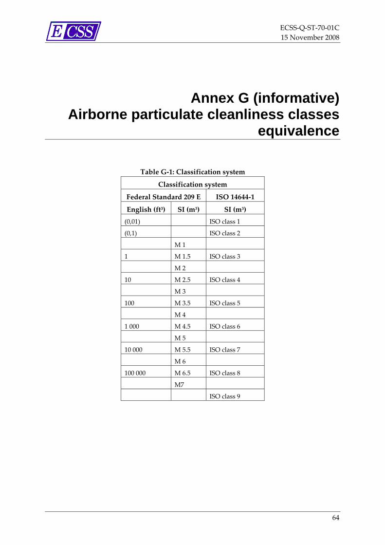
ECSS‐Q‐ST‐70‐01C 15 November 2008
Annex G (informative) Airborne particulate cleanliness classes
equivalence
Table G‐1: Classification system
Classification system
Federal Standard 209 E ISO 14644‐1
English (ft3) SI (m3) SI (m3) (0,01) ISO class 1
(0,1) ISO class 2
M 1
1 M 1.5 ISO class 3
M 2
10 M 2.5 ISO class 4
M 3
100 M 3.5 ISO class 5
M 4
1 000 M 4.5 ISO class 6
M 5
10 000 M 5.5 ISO class 7
M 6
100 000 M 6.5 ISO class 8
M7
ISO class 9
64
ECSS‐Q‐ST‐70‐01C 15 November 2008
Annex H (informative) Particulate levels on surfaces
H.1 Standard method 1: Particle distribution This can be done as per IEST‐STD‐CC1246D and ISO 14644‐9.
These documents give the size‐number distribution function for particles on surfaces.
Levels are measured by counting the number and sizes of the particles on a known surface area.
H.2 Standard method 2: Obscuration factor
H.2.1 Overview The obscuration factor (OF) is the ratio of the projected area of all particles to the total surface area on which they rest.
This OF is in principle independent of the number‐size distribution of the particles and even independent of the shape and colour of the particles. In general the levels are expressed in parts per million (mm2/m2) and acceptable values are roughly between 10 mm2/m2 and 10 000 mm2/m2.
The OF has the advantage that a number of performance loss parameters are directly related to the particle coverage of the critical item.
H.2.2 Correlation for particles on surfaces A correlation for particles on surface between levels of IEST STD 1246D and the obscuration factor is given in Table H‐1.
NOTE This correlation is theoretically based on ideal distribution of IEST‐ STD‐CC1246D (i.e. the slope factor of 0,926) and considering only particles between 1 μm and 10 μm.
65
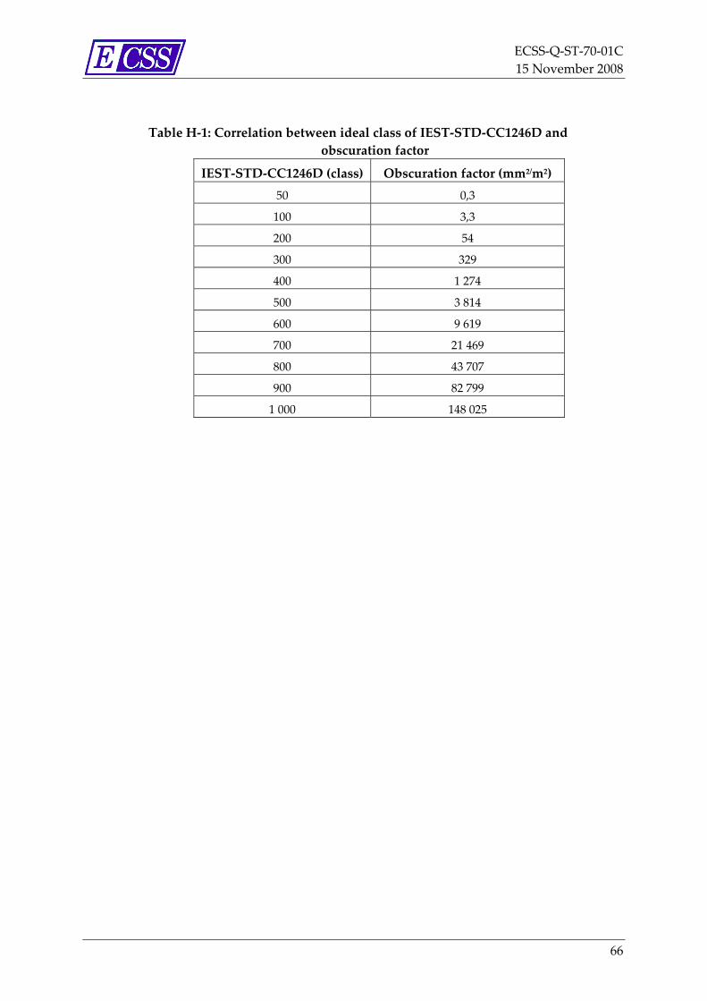
ECSS‐Q‐ST‐70‐01C 15 November 2008
Table H‐1: Correlation between ideal class of IEST‐STD‐CC1246D and obscuration factor
IEST‐STD‐CC1246D (class) Obscuration factor (mm2/m2) 50 0,3
100 3,3
200 54
300 329
400 1 274
500 3 814
600 9 619
700 21 469
800 43 707
900 82 799
1 000 148 025
66
ECSS‐Q‐ST‐70‐01C 15 November 2008
Annex I (informative) Compatibility of various solvents with
listed materials Table I‐1 shows examples of compatibility of various solvents with listed materials.
67
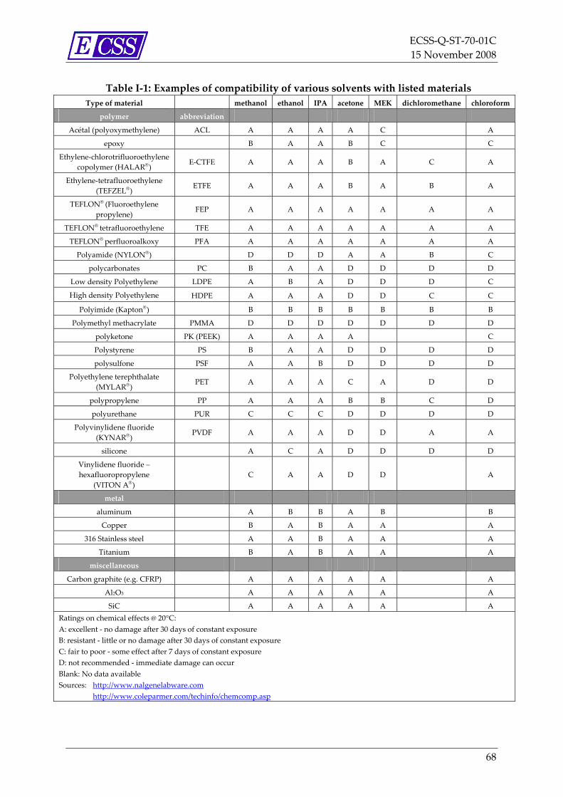
ECSS‐Q‐ST‐70‐01C 15 November 2008
Table I‐1: Examples of compatibility of various solvents with listed materials Type of material methanol ethanol IPA acetone MEK dichloromethane chloroform
polymer abbreviation
Acétal (polyoxymethylene) ACL A A A A C A
epoxy B A A B C C
Ethylene‐chlorotrifluoroethylenecopolymer (HALAR®) E‐CTFE A A A B A C A
Ethylene‐tetrafluoroethylene (TEFZEL®)
ETFE A A A B A B A
TEFLON® (Fluoroethylene propylene)
FEP A A A A A A A
TEFLON® tetrafluoroethylene TFE A A A A A A A
TEFLON® perfluoroalkoxy PFA A A A A A A A
Polyamide (NYLON®) D D D A A B C
polycarbonates PC B A A D D D D
Low density Polyethylene LDPE A B A D D D C
High density Polyethylene HDPE A A A D D C C
Polyimide (Kapton®) B B B B B B B
Polymethyl methacrylate PMMA D D D D D D D
polyketone PK (PEEK) A A A A C
Polystyrene PS B A A D D D D
polysulfone PSF A A B D D D D
Polyethylene terephthalate (MYLAR®)
PET A A A C A D D
polypropylene PP A A A B B C D
polyurethane PUR C C C D D D D
Polyvinylidene fluoride (KYNAR®)
PVDF A A A D D A A
silicone A C A D D D D
Vinylidene fluoride – hexafluoropropylene
(VITON A®) C A A D D A
metal
aluminum A B B A B B
Copper B A B A A A
316 Stainless steel A A B A A A
Titanium B A B A A A
miscellaneous
Carbon graphite (e.g. CFRP) A A A A A A
Al2O3 A A A A A A
SiC A A A A A A Ratings on chemical effects @ 20°C: A: excellent ‐ no damage after 30 days of constant exposure B: resistant ‐ little or no damage after 30 days of constant exposure C: fair to poor ‐ some effect after 7 days of constant exposure D: not recommended ‐ immediate damage can occur Blank: No data available Sources: http://www.nalgenelabware.com http://www.coleparmer.com/techinfo/chemcomp.asp
68
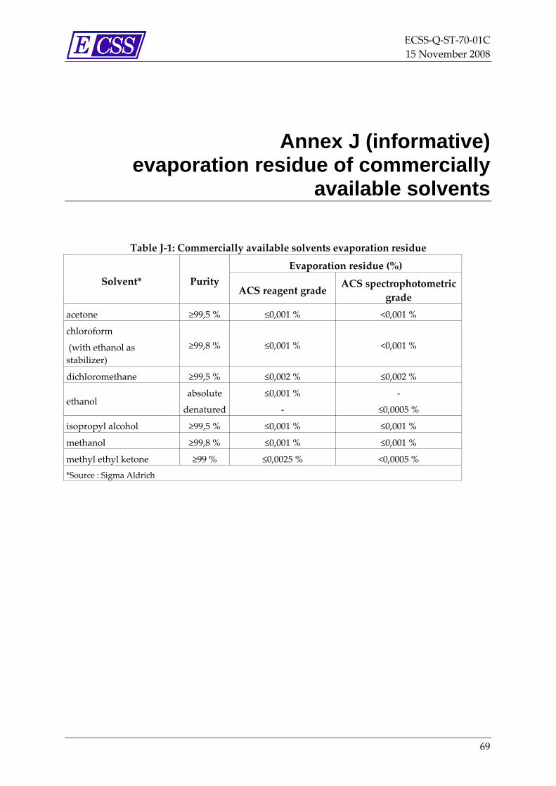
ECSS‐Q‐ST‐70‐01C 15 November 2008
Annex J (informative) evaporation residue of commercially
available solvents
Table J‐1: Commercially available solvents evaporation residue
Evaporation residue (%) Solvent* Purity
ACS reagent grade ACS spectrophotometric
grade acetone ≥99,5 % ≤0,001 % <0,001 %
chloroform
(with ethanol as stabilizer)
≥99,8 % ≤0,001 % <0,001 %
dichloromethane ≥99,5 % ≤0,002 % ≤0,002 %
ethanol absolute
denatured
≤0,001 %
‐
‐
≤0,0005 %
isopropyl alcohol ≥99,5 % ≤0,001 % ≤0,001 %
methanol ≥99,8 % ≤0,001 % ≤0,001 %
methyl ethyl ketone ≥99 % ≤0,0025 % <0,0005 % *Source : Sigma Aldrich
69

ECSS‐Q‐ST‐70‐01C 15 November 2008
Annex K (informative) Molecular contaminant content of some
wipe materials
Table K‐1: Molecular contaminant content of some wipe materials
NVR (g/m²) Wipe material Cleanroom class
IPA DIW Vectra alpha 10 ISO class 3‐4 0,05 0,02
absorbond ISO class 6‐7 0,01 0,005
Kimtech pure CL5 ISO class 5 0,01 0,03
Kimtech pure CL6 ISO class 6 0,01 0,03
70
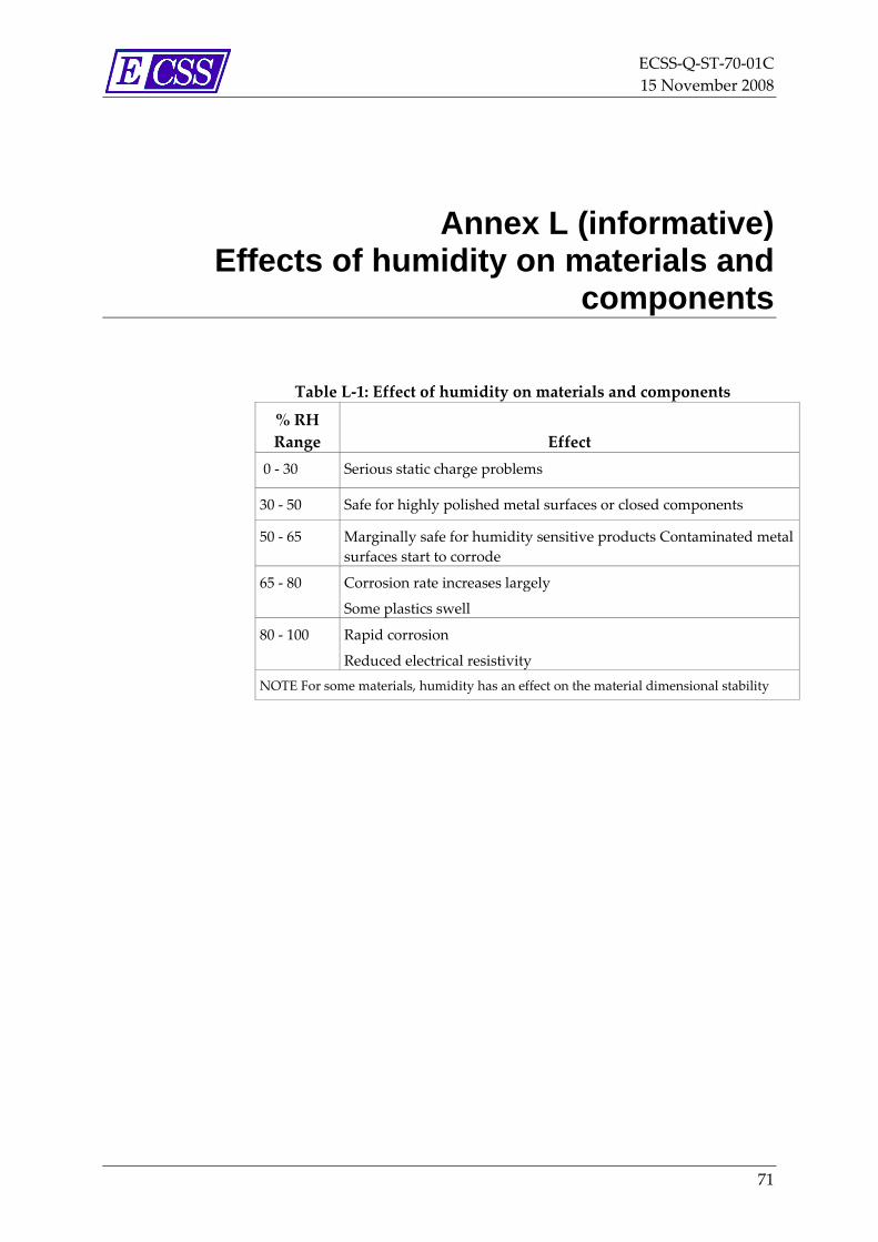
ECSS‐Q‐ST‐70‐01C 15 November 2008
Annex L (informative) Effects of humidity on materials and
components
Table L‐1: Effect of humidity on materials and components
% RH Range Effect
0 ‐ 30 Serious static charge problems
30 ‐ 50 Safe for highly polished metal surfaces or closed components
50 ‐ 65 Marginally safe for humidity sensitive products Contaminated metal surfaces start to corrode
65 ‐ 80 Corrosion rate increases largely
Some plastics swell
80 ‐ 100 Rapid corrosion
Reduced electrical resistivity NOTE For some materials, humidity has an effect on the material dimensional stability
71
ECSS‐Q‐ST‐70‐01C 15 November 2008
Annex M (informative) Cleaning methods
M.1 Removal of particulate contamination
M.1.1 Overview The removal of particulate contamination can be performed with, but not limited to, the methods described in M.1.2 to M.1.4
M.1.2 Vacuum cleaning and wiping • Dust can be removed with the aid of an ordinary vacuum cleaner,
combined with a good brush. Having the exhaust of the vacuum cleaner outside the cleanroom is preferred to avoid recontamination. Clean air supply to the item to be cleaned is used, otherwise the contamination of items to be cleaned can be increased by the relative dirty air which is extracted from the environment (e.g. when electrostatic attraction can occur). Only vacuum cleaners equipped with HEPA filters are used in a cleanroom and checked with a UV lamp while working.
• Wiping is performed with extreme care, otherwise surfaces can be scratched and “dust” can simply be wiped onto other clean items in the vicinity.
Since, in any case, solvent leads particles to the bottom of cleaned part, those particles should be recovered with a vacuum cleaner at the end.
• An effective form of wiping can be used of tissues dipped in methanol.
M.1.3 Gas jet cleaning • Another method of removal of particles is the very careful use of a jet of
compressed gas, since contamination of the other clean items in the vicinity can result. Cleaning agents, such as brushes, wipe tissues or compressed gas, can themselves contaminate the item to be cleaned and can lead to dust scratching the surface during cleaning. Ionized air is a good approach in the removal of particles by air blowing.
• Cleaning with dry ice (e.g. CO2 jet spray) can be very effective.
72

ECSS‐Q‐ST‐70‐01C 15 November 2008
M.1.4 Tapes and films trapping • Larger particles can be removed by means of polyimide adhesive tape,
eventually rolled around a metal or other appropriate tool (e.g. swabs).
• The hardware to be cleaned can be coated with shrinkable polymer film and, after drying, the film can be removed with the contaminants. Use of this type of cleaning method needs to be carefully evaluated as it is known to have detrimental effects on some materials (e.g. gold coatings).
M.2 Removal of molecular contamination
M.2.1 Overview The removal of molecular contamination can be performed with, but not limited to, the methods described in M.2.2 to M.2.8.
M.2.2 Mechanical cleaning • Dry wiping: clean lint‐free cloth or lens paper is used, however, it has the
disadvantage that it can scratch the surfaces.
• Wet wiping: a clean cloth or paper is used in conjunction with organic solvents.
• Other mechanical cleaning are grinding, brushing and blasting.
M.2.3 Solvent and detergent cleaning • Solvent cleaning: examples are washing, dipping, spraying, vapour
cleaning and ultrasonic cleaning.
• Detergent cleaning or soap cleaning: Detergent cleaning (or soap cleaning) for, for example, glass, rubbers, plastics, polyamides, PTFE, polypropylene and acrylates and all ferrous metals, including stainless steel. Such detergents also clean non‐ferrous metals, such as aluminium and brass, but have an oxidizing effect on their surface. A detergent or soap cleaning is followed up by a final cleaning with solvent to remove all traces of detergent.
• Chemical or electrochemical cleaning with, for example, acids, alkalines and salts for smoothing metal surfaces
M.2.4 Films trapping • Use of shrinkable polymer film, peeled after drying, can also be very
effective for the removal of molecules (not for optical surfaces).
M.2.5 Gas jet cleaning • Cleaning with dry ice (CO2 jet spray): this is very effective for the
removal of molecular layers.
73

ECSS‐Q‐ST‐70‐01C 15 November 2008
M.2.6 Plasma cleaning • Cleaning with ionized inert low pressure gas: This is very effective for
the removal of polymerized products.
M.2.7 Bakeout • Volatilizing under vacuum is especially successful for cleaning
assembled units, or when solvent cleaning is too delicate an operation.
M.2.8 Ultra-violet-ozone cleaning • Molecules of an organic nature are activated by ultra‐violet light,
resulting in dissociation, after which they react with the ozone produced in the air by ultra‐violet light.
74

ECSS‐Q‐ST‐70‐01C 15 November 2008
Bibliography
ECSS‐S‐ST‐00 ECSS system – Description, implementation and general requirements
ECSS‐Q‐ST‐10 Space product assurance – Product assurance management
ECSS‐Q‐ST‐70‐05 Space product assurance – Detection of organic contamination of surfaces by infrared spectroscopy
ECSS‐E‐ST‐10‐04 Space engineering – Space environment
ASTM E1216 87(1992) Standard Practice for Sampling for Surface Particulate Contamination by Tape Lift
ASTM E1235M 95 Standard Test Method for Gravimetric Determination of Nonvolatile Residue (NVR) in Environmentally Controlled Areas for Spacecraft
ASTM E1559 93 Standard Test Method for Contamination Outgassing Characteristics of Spacecraft Materials
ISO 15388 Contamination and Cleanliness Control
NASA SP 5076 Contamination control handbook
MIL HDBK 406 Contamination control technology cleaning materials for precision precleaning and use in cleanrooms and clean work
75