space spray application of insecticides for vector...
TRANSCRIPT
Communicable Disease Control, Prevention and EradicationWHO Pesticide Evaluation Scheme (WHOPES)
World Health Organization Geneva
For more information, please contact:
CDS Information Resource CentreWorld Health Organization1211 Geneva 27, SwitzerlandFax: +(41) 22 791 4285E-mail: [email protected]
Space spray application ofinsecticides for vector and public health pest control
A practitioner’s guide
WHO/CDS/WHOPES/GCDPP/2003.5

WHO/CDS/WHOPES/GCDPP/2003.5
Space spray application of insecticides
for vector and public health pest control
A practitioner’s guide
WORLD HEALTH ORGANIZATIONGeneva
Communicable Disease Control, Prevention and EradicationWHO Pesticide Evaluation Scheme (WHOPES)

© World Health Organization 2003All rights reserved.
The designations employed and the presentation of the material in this publication do not implythe expression of any opinion whatsoever on the part of the World Health Organization con-cerning the legal status of any country, territory, city or area or of its authorities, or concerningthe delimitation of its frontiers or boundaries. Dotted lines on maps represent approximateborder lines for which there may not yet be full agreement.
The mention of specific companies or of certain manufacturers’ products does not imply thatthey are endorsed or recommended by the World Health Organization in preference to othersof a similar nature that are not mentioned. Errors and omissions excepted, the names of pro-prietary products are distinguished by initial capital letters.
The World Health Organization does not warrant that the information contained in thispublication is complete and correct and shall not be liable for any damages incurred as a resultof its use.

Page
Acknowledgements 5
1. Introduction 7
2. Space spray treatments 8
2.1 Thermal fog 8
2.2 Cold fog 9
3. Space spray equipment 10
3.1 Equipment for thermal fogging 103.1.1 Hand-carried thermal foggers 103.1.2 Vehicle-mounted thermal foggers 123.1.3 Aircraft application of thermal fogs 12
3.2 Equipment for cold fog application 123.2.1 Hand-carried cold foggers 123.2.2 Vehicle-mounted cold foggers 133.2.3 Aircraft application of cold fogs 15
4. Insecticide products for space spraying 16
5. Space spray treatments –general considerations 17
5.1 Optimum droplet size 17
5.2 Droplet size parameters 19
5.3 Flow rate 19
5.4 Spray concentration 21
5.5 Wind speed 21
5.6 Wind direction 22
5.7 Temperature effects 22
5.8 Time of treatment 23
WHO/CDS/WHOPES/GCDPP/2003.5 3
Conte
nts

6. Operational guidelines 25
6.1 Pre-spray activities 256.1.1 Planning and needs assessment 256.1.2 Calibration of the equipment 276.1.3 Droplet sizing 29
6.2 Application procedures 346.2.1 Operator protection 346.2.2 Indoor fogging 346.2.3 Outdoor ground fogging 356.2.4 Aerial application of fogs 37
6.3 Monitoring spraying operations 38
6.4 Evaluation 38
6.5 Equipment maintenance 39
6.6 Pesticide storage and disposal 39
7. Selected readings 40
Annex 1.Daily application report (portable and vehicle-mounted equipment) 41
Annex 2.Maintenance record 42
Annex 3.Routine machine performance check 43
4 WHO/CDS/WHOPES/GCDPP/2003.5
Conte
nts

Acknowledgements
The Department of Communicable Disease Control, Preventionand Eradication (CPE) wishes to thank the following for theircritical review of this publication and for their valuable commentsand suggestions:
• Dr J.R. Brown, Navy Disease Vector Ecology and Control,Jacksonville, Florida, USA
• Dr M.S. Chang, World Health Organization, Phnom Penh,Cambodia
• Dr D. Dame, Gainesville, Florida, USA• Dr C. Frederickson, Pan American Health Organization,
Brasilia, Brazil• Dr J. Invest, Aylesbury, Buckinghamshire, England• Dr G. Matthews, International Pesticide Application Research
Centre, Imperial College, Berkshire, England• Dr M. Nathan, Communicable Disease Control, Prevention and
Eradication, World Health Organization, Geneva, Switzerland• Dr H.H. Yap, Universiti Sains Malaysia, Penang, Malaysia• Dr P. Wege, Syngenta, Bracknell, Berkshire, England• Dr M. Zaim, Communicable Disease Control, Prevention and
Eradication, World Health Organization, Geneva, Switzerland
CPE also wishes to thank Mr Trevor Metcalfe, Hampshire, England for the preparation of the illustrations.
Preparation of this document has been funded by the GlobalCollaboration for Development of Pesticides for Public Health(GCDPP).
WHO/CDS/WHOPES/GCDPP/2003.5 5


1.Introduction
This guide provides information on how to control flying insect pests andvectors of diseases by applying insecticides as space treatments. Spacetreatments are usually designed to provide a rapid knock-down and mor-tality with little or no residual effect. Such treatments must be consideredin conjunction with other control methods as part of an integrated vectormanagement programme. Space spraying provides a rapid method ofcontrol in emergency or epidemic situations and may be used for seasonalcontrol of flying insect pests or vectors. However, it may not be ideal forall vectors or situations and as such may not be an economical methodof control.
The aim of space treatments is to rapidly reduce populations of flying insectpests and vectors. An additional objective may be to reduce or interruptthe transmission cycle of insect-borne diseases. Among the disease vectorsaffecting public health, the most important and widespread are mosqui-toes, houseflies, sandflies and other biting flies; some of these may be tar-geted for space treatment.
Immediate killing of actively flying insects requires a cloud of insecticidedroplets that they will encounter in flight. To be cost-effective and obtaingood biological efficacy, space spraying requires:
■ knowledge of the behaviour and biology of the target species – tounderstand where and when space treatments will be effective;
■ knowledge of insecticides and formulations most suitable for spacespraying;
■ knowledge of pesticide application technology – to know which equip-ment is needed and how to use it; and
■ monitoring and surveillance of the target species and vector-borne disease problem to evaluate the efficacy of the programme.
WHO/CDS/WHOPES/GCDPP/2003.5 7

2.Space spray treatments
A space spray – technically a fog (sometimes referred to as an aerosol) –is a liquid insecticide dispersed into the air in the form of hundreds of mil-lions of tiny droplets less than 50 µm in diameter. It is only effective whilethe droplets remain airborne. Space sprays are applied mainly as thermalfogs or cold fogs.
2.1 Thermal fog
The insecticide used in thermal fogs is diluted in a carrier liquid, which isusually oil-based. Hot gas is used to heat the pesticide spray, decreasingthe viscosity of the oil carrier, and vaporizing it. When it leaves the nozzlethe vapour hits colder air and condenses to form a dense white cloud offog. Most of the droplets are smaller than 20 µm. The droplet size isaffected by the interaction between the formulation, the flow rate andthe temperature at the nozzle (usually > 500 °C). The volume of spray mix-ture applied in vector control is usually 5–10 litres per hectare, with anabsolute maximum of 50 litres per hectare. The hot emission gas is obtainedfrom engine exhaust, friction plate/engine exhaust or from a pulse jetengine.
Advantages
• Easily visible fog so dispersal and penetration can be readily observedand monitored;
• Good public relations in some circumstances as people can see some-thing being done about the problem; and
• Low concentration of active ingredient in the spray mixture and reducedoperator exposure.
8 WHO/CDS/WHOPES/GCDPP/2003.5

Disadvantages
• Large volumes of organic solvents are used as diluents, which may havebad odour and result in staining;
• High cost of diluent and spray application;
• Householders may object and obstruct penetration of fog into housesby closing windows and doors;
• Fire risk from machinery operating at very high temperatures with flam-mable solvents; and
• Can cause traffic hazards in urban areas.
2.2 Cold fog
With cold fogs the droplets are formed by the mechanical breaking upof the spray mixture, either by passing it through high-pressure nozzlesor by passing a slow stream of the mixture through a high-velocity vortexof air. Some equipment is fitted with high-speed rotary nozzle(s). Thespray droplets are generated without any external heat. With cold fogsthe volume of spray is kept to a minimum. Ultra-low-volume insecticideformulations are commonly used for such applications.
Advantages
• The amount of diluent is kept to a minimum, resulting in lower appli-cation cost and increased acceptability. Some formulations are ready touse, thereby reducing operator exposure;
• May use water-based and water-diluted formulations, which pose alow fire hazard and are more environmentally friendly;
• Because a lower volume of liquid is applied, application is more efficient;and
• No traffic hazard as the spray cloud is nearly invisible.
Disadvantages
• Dispersal of the spray cloud is difficult to observe; and
• Higher technical skills and regular calibration are required for efficientoperation of equipment.
WHO/CDS/WHOPES/GCDPP/2003.5 9

3.Space spray equipment
Selection of appropriate equipment for space spraying depends on thesize and accessibility of the target area as well as the human resourcesand operational capacity of the programme. Sometimes smaller machinesmay be needed in conjunction with vehicle-mounted equipment to treatnarrow pathways and other areas inaccessible to vehicles or shelteredfrom prevailing air movements, e.g. the lee side of buildings and insidedwellings.
Cold fog equipment is recommended where thermal fogs may cause atraffic hazard. Aerial application of space sprays may be justified whereaccess with ground equipment is difficult and/or extensive areas need tobe treated very quickly. This, however, requires aerial spraying expertise,which is unavailable in most control programmes so that the task usuallyhas to be contracted out.
The selection of equipment should ideally be based on familiarity, suit-ability and performance. Advances in equipment design should be con-sidered when purchasing equipment.
A brief description of the main types of space spray equipment is providedbelow. More detailed information, as well as WHO specifications forquality control of pesticide application equipment, is available in theWHO manual, Equipment for Vector Control 1.
3.1 Equipment for thermal fogging
3.1.1 Hand-carried thermal foggers
These are used for treating houses and certain outdoor areas of limitedsize or accessibility, e.g. markets, hotel grounds and parks (Figure 1).There are two types of hand-carried thermal foggers, pulse jet and fric-tion plate.
10 WHO/CDS/WHOPES/GCDPP/2003.5
1 Equipment for vector control. Geneva, World Health Organization, 1990.

Pulse jet
These machines are fitted with a pump (piston, bellows or electric) anda set of batteries linked to a spark plug. To start the engine, the pump isoperated and the switch used to connect the battery power to the sparkplug. When petrol is ignited in the combustion chamber by the sparkplug, the batteries are no longer used as the hot exhaust gas ignites sub-sequent charges of fuel and air. A pulse jet engine will continue to operateas long as fuel is supplied through the carburettor. The hot exhaust movesdown a long tube to the nozzle, where the insecticide is injected into thehot gas. The machine operates with a very loud pulsating noise. A simplefixed restrictor controls the flow rate on most machines. Flow rates upto 25 litres per hour may be achieved. Machines should be fitted with asafety valve to stop the flow of insecticide to the nozzle when the engineceases to operate.
Friction plate
This type of machine consists of a 1–3 hp 2-cycle engine driving a “fric-tion plate” inside the insecticide tank, which preheats the insecticide andfuel oil mixture. This plate also serves as part of the pump that delivers
WHO/CDS/WHOPES/GCDPP/2003.5 11
Pesticide
injection system
Pesticide
tank
Fuel tank
Hand
pump
Combustion
chamber guard
Spark plug
Combustion
chamber
Carburettor
Button
for ignition
Figure 1. A hand-carried thermal fogger

the liquid to the engine exhaust. The hot exhaust gases generate and dis-perse the fog. Friction plate devices operate at a lower temperature thanpulse jet engines.
3.1.2 Vehicle-mounted thermal foggers
Large thermal fog generators use an air-cooled motor to run an air blower,fuel pump and insecticide pump. Air from the “roots type air blower” isdelivered into the combustion chamber. There it is mixed with gasolinevapour and ignited, so that temperatures reach 426–648 °C. The dilutedinsecticide liquid is pumped via a simple flow delivery valve and injectedinto a cup in the fog head or directly into the nozzle. The insecticideliquid is vaporized by the blast of hot gases. Despite this high tempera-ture, trials with some insecticides recovered at the jet tip show very littledegradation of active ingredient. This is because the time spent at thattemperature is only a fraction of a second, which is not long enough tocause serious degradation. The hot gases then pass out of the machine.As the hot oil vapour is discharged through a relatively large nozzle intothe cooler outside air, it condenses to form very small droplets of thickwhite fog. Delivery rates of up to 10 litres per minute can be achieved withlarger machines.
3.1.3 Aircraft application of thermal fogs
For aircraft application of thermal fogs the diluted insecticide formula-tion is fed into the aircraft exhaust. The exhaust is adapted with vanesto swirl the fog droplets as they are formed. The application of thermalfogs by aircraft has been very limited.
3.2 Equipment for cold fog application
3.2.1 Hand-carried cold foggers
Most of these machines have a 1–3 hp, 2-cycle gasoline engine whichdrives a blower unit to discharge air through the nozzle. Air may also slightlypressurize the insecticide formulation tank so that the liquid is fed via arestrictor to the nozzle. However, negative pressure generated by theair flow passing through the nozzle allows liquid to flow from the tank.
12 WHO/CDS/WHOPES/GCDPP/2003.5

These machines are small and weigh 6–11 kg. In addition to hand-carriedunits, knapsack cold fogging units are also available (Figure 2), as areseveral electrically driven models.
Flow rates range from 1 to 4 litres per hour. A metering valve or prefer-ably a fixed or changeable orifice controls the flow rate. These machinesare ideal for indoor space treatments and for small areas outdoors wherevehicle access is limited.
3.2.2 Vehicle-mounted cold foggers
A 5–20 hp 4-stroke gasoline engine is used to drive a high volume airblower, forcing air at a rate of approximately 6 m3 per minute at lowpressure (50 kPa) to one or more nozzles (Figure 3). The angle of projec-tion of the cold fog from these nozzles can be adjusted. The pesticide container may be pressurized to force the formulation to the nozzle, orpositive-displacement pumps may be used.
WHO/CDS/WHOPES/GCDPP/2003.5 13
Pesticidetank
Knapsackframe
2–strokeengine
Blowerunit
Cold fognozzle
Respiratoryprotectiveequipment(RPE)
Figure 2. A knapsack cold fogger

Where positive-displacement pumps are used, they can be linked electricallyto the vehicle in order to vary output as a function of vehicle speed. Inparticular, spraying ceases when the vehicle stops.
Alternatively a high-pressure, low-volume air source is used with an aircompressor, rather than a blower. On these machines, nozzles ranging fromthe standard industry “paint gun nozzle” to proprietary nozzles thatatomize well up to a flow rate of 0.5 litre per minute are available.Another design uses a rotary nozzle coupled with an electric motor whichoperates at a very high speed.
14 WHO/CDS/WHOPES/GCDPP/2003.5
Figure 3. A vehicle-mounted cold fogger

3.2.3 Aircraft application of cold fogs
Both fixed-wing aircraft and helicopters have been used to apply cold fogs.Conventional low-volume nozzles (e.g. flat fan) have been used on fixed-wing aircraft to create fine sprays, using moderate or high pressures.However, the droplet spectrum is generally poor so preference is givento the use of rotary atomizers or very-high-pressure systems.
A rotary atomizer (Figure 4) has a cylindrical metal gauze rotated at highspeed by an electric motor or by fan blades rotated by the forward speedof the aircraft. The pitch of the blades is adjustable so that the rotationalspeed of the atomizer can be set in relation to the aircraft speed. In addi-tion to the centrifugal force producing droplets, air shear breaks theliquid into smaller droplets.
WHO/CDS/WHOPES/GCDPP/2003.5 15
Mounting
boom
Wire mesh gauze
Variable
restrictor
unit
Diaphragm check valve
Mounting clamp
with shock bush
Adjustable fan
blades
Figure 4. A rotary atomizer for aircraft application of cold fogs
4.Insecticide products for space spraying
Space-spraying formulations have traditionally been oil-based. The oil car-rier inhibits evaporation of small fog droplets. Only insecticide productswith highflash points should be used for thermal fogging.
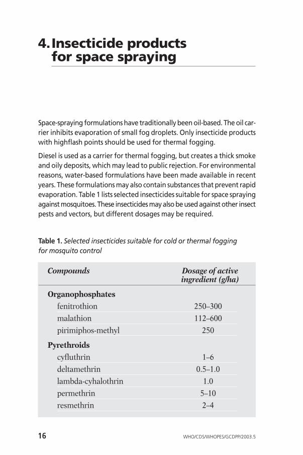
Diesel is used as a carrier for thermal fogging, but creates a thick smokeand oily deposits, which may lead to public rejection. For environmentalreasons, water-based formulations have been made available in recentyears. These formulations may also contain substances that prevent rapidevaporation. Table 1 lists selected insecticides suitable for space sprayingagainst mosquitoes. These insecticides may also be used against other insectpests and vectors, but different dosages may be required.
Table 1. Selected insecticides suitable for cold or thermal fogging for mosquito control
Compounds Dosage of active ingredient (g/ha)
Organophosphates
fenitrothion 250–300
malathion 112–600
pirimiphos-methyl 250
Pyrethroids
cyfluthrin 1–6
deltamethrin 0.5–1.0
lambda-cyhalothrin 1.0
permethrin 5–10
resmethrin 2–4
16 WHO/CDS/WHOPES/GCDPP/2003.5

Formulations for space spraying are:
Hot fogging concentrate (HN). A formulation suitable for application bythermal fogging equipment, either directly or after dilution.
Ultra-low-volume liquid (UL). A homogenous liquid ready for use throughULV equipment which is specially formulated for low volatility.
Emulsion, oil in water (EW). A heterogenous fluid formulation consistingof a solution of insecticide in an organic liquid dispersed as fine globulesin a continuous water phase.
Emulsifiable concentrate (EC). A homogenous liquid formulation to beapplied as an emulsion after dilution in water or oil.
Formulations such as wettable powders (WP), suspension concentrates (SC)and water-dispersible granules (WG) are unsuitable for space spraying.An appropriate formulation must be chosen and the label instructions care-fully followed for all applications. WHO specifications for pesticides, for qualitycontrol and international trade, are available at: www.who.int/ctd/whopes.
5.Space spray treatments –general considerations
5.1 Optimum droplet size
Space treatments are only effective while the droplets remain airborne.Droplets will fall by gravity and some are deposited on horizontal surfaceswhile the majority will be lost to the atmosphere especially in outdoorspraying.
The speed at which droplets fall is determined by the mass of the droplet,e.g. a droplet of 20 µm diameter will fall at 0.012 minute per second,taking 14 minutes to fall 10 metres in still air, whereas a 100 µm dropletfalls at 0.279 minute per second and will take only 36 seconds to fall thesame distance (Table 2).
WHO/CDS/WHOPES/GCDPP/2003.5 17

Droplets bigger than 30 µm in diameter are less effective as they do notremain airborne for sufficient time. Droplets smaller than 5 µm in diam-eter do not readily come in contact with flying insects, as the movementof the smallest droplets is affected by the air turbulence created by theinsect’s flight. It is generally accepted that droplets should be generatedat 10–30 µm so that, even with some evaporation and after some time,they remain in the correct range for optimal airborne suspension andinsect impact.
Table 2. Density and fall of fog droplets when applied at the rate of 1 litre per hectare (a theoretical model)
Droplet size Time to fall Droplet density(µm) 10 m (no./cm3)
1 93.7 hours 19120.05 3.7 hours 152.0
10 56 minutes 19.220 14 minutes 2.3850 135 seconds 0.150
100 36 seconds 0.0192
In dry climates, especially if the pesticide is diluted in a volatile carrier (e.g.water), the evaporation of the diluent will cause the droplets to shrink;slightly larger droplets are thus desirable.
For a given volume of spray mixture, the smaller the droplet size thegreater the number of droplets. If 1 ml of spray mixture is dispersed as20 µm droplets (each containing 4.2 picolitres), there will be 239 milliondroplets produced, whereas if the same volume is dispersed as 100 µmdroplets (534 picolitres) there will be 1.91 million droplets. The largenumber of droplets greatly increases the chances of contact being madewith a flying insect as the density per unit volume of air will be so muchgreater (see Table 2).
The optimum droplet size for space spraying against mosquitoes is10–20 µm, for larger flies, e.g. tsetse flies, the optimum is 30 µm.
18 WHO/CDS/WHOPES/GCDPP/2003.5
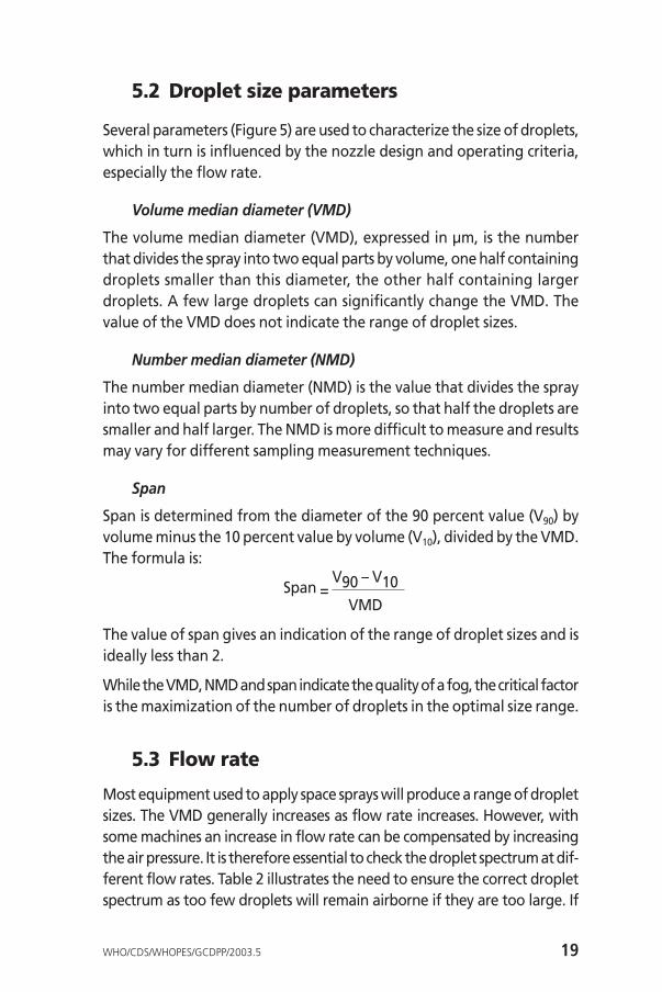
5.2 Droplet size parameters
Several parameters (Figure 5) are used to characterize the size of droplets,which in turn is influenced by the nozzle design and operating criteria,especially the flow rate.
Volume median diameter (VMD)
The volume median diameter (VMD), expressed in µm, is the numberthat divides the spray into two equal parts by volume, one half containingdroplets smaller than this diameter, the other half containing largerdroplets. A few large droplets can significantly change the VMD. Thevalue of the VMD does not indicate the range of droplet sizes.
Number median diameter (NMD)
The number median diameter (NMD) is the value that divides the sprayinto two equal parts by number of droplets, so that half the droplets aresmaller and half larger. The NMD is more difficult to measure and resultsmay vary for different sampling measurement techniques.
Span
Span is determined from the diameter of the 90 percent value (V90) byvolume minus the 10 percent value by volume (V10), divided by the VMD.The formula is:
Span =V90 – V10
VMD
The value of span gives an indication of the range of droplet sizes and isideally less than 2.
While the VMD, NMD and span indicate the quality of a fog, the critical factoris the maximization of the number of droplets in the optimal size range.
5.3 Flow rate
Most equipment used to apply space sprays will produce a range of dropletsizes. The VMD generally increases as flow rate increases. However, withsome machines an increase in flow rate can be compensated by increasingthe air pressure. It is therefore essential to check the droplet spectrum at dif-ferent flow rates. Table 2 illustrates the need to ensure the correct dropletspectrum as too few droplets will remain airborne if they are too large. If
WHO/CDS/WHOPES/GCDPP/2003.5 19
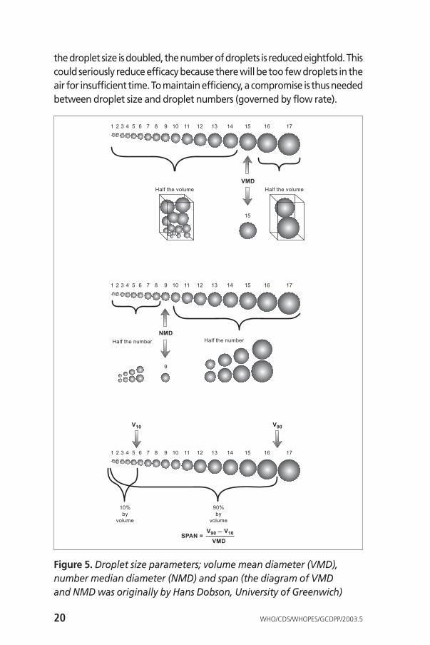
the droplet size is doubled, the number of droplets is reduced eightfold. Thiscould seriously reduce efficacy because there will be too few droplets in theair for insufficient time. To maintain efficiency, a compromise is thus neededbetween droplet size and droplet numbers (governed by flow rate).
20 WHO/CDS/WHOPES/GCDPP/2003.5
1 2 3 4 5 6 7 8 9
9
10 11 12 13 14 15 16 17
Half the number Half the number
NMD
1 2 3 4 5 6 7 8 9 10 11 12 13 14 15 16 17
10%
by
volume
90%
by
volume
V90SPAN =
V10
VMD
1 2 3 4 5 6 7 8 9 10 11 12 13 14 15
15
16 17
Half the volumeHalf the volume
VMD
V10 V90
Figure 5. Droplet size parameters; volume mean diameter (VMD),number median diameter (NMD) and span (the diagram of VMD and NMD was originally by Hans Dobson, University of Greenwich)
5.4 Spray concentration
The manufacturer’s recommendations for the targeted amount of activeingredient per unit area must remain within the specified range. How-ever, the spray concentration and the rate of application can be adjusted.Any dilution of the formulation must be compensated by an increase inthe volume of spray per unit area (this can be achieved by increasing theflow rate of the machine, slowing the ground or air speed at which themachine travels, or reducing the swathe width).
For a flying insect to be killed, it must acquire a lethal dose of insecticidein the droplets that impact on it. The lower the concentration of activeingredient, the larger the number of droplets of a given size required toachieve a lethal dose.
Ultra-low-volume spraying aims, largely for operational reasons, to min-imize the total volume of diluted insecticide applied (usually < 2 litresper hectare).
5.5 Wind speed
Wind speed has a profound effect on droplet distribution and impinge-ment on insects. In most situations a wind speed of 1–4 metres per second(approximately 3.6–15 km/hour) is needed to drift the droplets down-wind from the line of travel. Spraying should not take place when windspeed exceeds 15 km/hour. Wind speed can be measured using a hand-held anemometer.
The type of terrain and vegetation affects air movement and hence thedistribution of the droplets. In open terrain with relatively sparse vege-tation, wider effective swathes can be obtained than in urban areaswhere the obstruction of buildings alters the flow of air. Penetration ofdroplets into houses depends on the design of the house and whetherwindows, doors and eaves are open. In urban environments the roadlayout determines the route; however, this may not correspond to the effec-tive swathe width. An increase in the volume application rate may beneeded to compensate for reduced droplet penetration into areas ofvegetation. For practical purposes most manufacturers consider a 50-metre swathe as the basis for calculating recommended application rates.
WHO/CDS/WHOPES/GCDPP/2003.5 21

5.6 Wind direction
With vehicle-mounted and aerial spraying the spray route must takeaccount of the wind direction to maximize the distribution of the spraythroughout the target area. Figure 6 illustrates the spray applicationroute relative to wind direction.
5.7 Temperature effects
In direct sunlight the ground is heated. This causes air to rise. In the middleof the day outdoor space spraying will largely be wasted as the spraydroplets will tend to rise upwards rather than drift horizontally. Ideallyan inversion is needed, i.e. colder air closer to the ground. This generally
22 WHO/CDS/WHOPES/GCDPP/2003.5
25ºDo notspray
25ºDo notspray
Optimum
wind
direction
Spray drift
Path of spray delivery
Figure 6. Spray application route relative to wind direction

occurs early in the morning after the ground temperature has fallenduring the night, but can also occur in the evening when the sun has setand ground temperatures begin to fall. Under an inversion spray dropletswill drift close to the ground. Air characteristics, ideal for ground andaerial space spraying, can be observed from smoke rising from chimneysor fires, or can be checked using smoke generators (Figure 7).
5.8 Time of treatment
Local knowledge of the time(s) of peak flight activity of the target speciesis crucial to ensure that space treatments are planned to coincide, as far aspossible, with these times (Figure 8). Fortunately, peak flight activity ofmany vectors is around dusk and/or dawn, when weather conditions areoften favourable for space treatment. However, some insects, notablyhouseflies and similar species, are more active during the day and beforesunset. Aedes aegypti and Aedes albopictus, mosquito vectors of denguefever, are active during daytime, with peak flight activity in the morning
WHO/CDS/WHOPES/GCDPP/2003.5 23
A B
C
Figure 7.Air movement as indicated by smoking chimneys: (A) still; (B) in wind; (C) under inversion.

and afternoon. With these species a compromise is usually made outdoorsby spraying in the early morning or late afternoon. The timing is less impor-tant if indoor spraying is conducted. When other flies are active in the day-time, and conditions are not ideal for spraying because of high temperatures,treatments are usually conducted in the morning before temperatures gettoo high.
Figure 8. Illustrative examples of optimal space spray application timerelative to flight activity of target species (A, crepuscular; B, diurnal; C, nocturnal) and temperature
24 WHO/CDS/WHOPES/GCDPP/2003.5
tem
pera
ture
fligh
t act
ivit
yfli
ght a
ctiv
ity
fligh
t act
ivit
y A
12:0006:00
time
18:00 24:00 06:00
B
C

6.Operational guidelines
6.1 Pre-spray activities
Before embarking on any space spray treatment it is essential to clearlydefine the problem, the pest species involved and its behaviour, and tocharacterize the area for treatment. This will allow for appropriate plan-ning and will ensure that all the equipment and resources required areavailable for timely and efficient operations.
6.1.1 Planning and needs assessment
When planning a space spray operation it is necessary to identify thelocation and magnitude of the pest or vector-borne disease problem andthe epidemiological situation. The pest species or vector and its breedingsites must also be identified. The latter will assist in defining the geo-graphical area to be targeted for spray operations. The flight behaviourand peak flight activity times of the target species must be ascertainedto optimize the effectiveness of the operation through proper timing ofthe spraying.
The area for space treatment must be well defined and characterized,including the density of the human population, type of dwellings/build-ings, road layout, vegetation and accessibility. These factors will assist indetermining the most appropriate space spray application method(s) andchoice of equipment. Vehicle-mounted equipment is suitable only if thereis a good network of roads. Portable equipment is more versatile andcan complement vehicle-mounted equipment for spraying areas that areotherwise inaccessible and for treating the insides of buildings, but cov-erage is slower. Aerial treatments are usually limited to extensive areasrequiring rapid coverage or to large areas with poor ground access.
Maps are needed to facilitate advance planning of spray routes. If suit-able maps of the area are unavailable it may be necessary to preparethem. The total area in hectares should be calculated and then the options
WHO/CDS/WHOPES/GCDPP/2003.5 25

for spray routes must be established. The route distances and vehicle orwalking speeds should be calculated so that the correct dosage can beapplied for the flow rate of the machine.
When choosing an insecticide product, consideration must be given tothe susceptibility of the vector to the insecticide compound and to thesuitability of the product for the application equipment. WHO standardtest kits and procedures for determining susceptibility (details are avail-able from WHO Communicable Disease Control, Prevention and Eradi-cation, 1211 Geneva 27, Switzerland) should be used and the implicationsof the results on the efficacy of the spray operations should be deter-mined. It is noteworthy that there are insecticide products for space sprayingwhich contain synergists to offset the effects of certain insecticide resist-ance mechanisms.
Selected insecticides for space spraying are listed in Table 1. Final applicationcosts per hectare for the recommended dosage should also be calculatedand compared when making the decision on which insecticide to pur-chase. This calculation will include the cost of handling and transportationas well as that of any diluent/carrier which may be needed. WHO specifi-cations for pesticides (http://www.who.int/ctd/whopes) should be usedfor quality control.
In choosing application equipment and insecticide products for spacespraying, after-sales services of the manufacturer should be taken intoconsideration. These include training and disposal of insecticide con-tainers. The value of these additional services is increasingly importantin relation to the overall costs of the spray programme.
In order to decide on the number of treatments and the interval betweentreatments, the purpose of the operation must be well-defined, i.e. abate-ment of nuisance species or interruption of transmission of a vector-bornedisease. For the latter, the interval will be less than the incubation periodof the pathogen in the vector.
The number and type of machines (e.g. portable or vehicle-mounted),and the number of machine operators and ancillary personnel will bedetermined by the size and characteristics of the area to be treated, thetime needed to complete each application cycle and its frequency. Con-sider the following example: 1000 hectares per day must be sprayed byvehicle-mounted equipment. Operations are limited by weather condi-
26 WHO/CDS/WHOPES/GCDPP/2003.5
tions and flight activity of the target species to 2–3 hours in the evening.Assuming that one machine can cover 60 hectares per hour (180 hectaresin 3 hours of operation), six machines will be needed to complete thistask in one evening. Alternatively, three machines can treat the area intwo evenings.
Two persons are normally needed for each vehicle-mounted fogger,one to drive and the other to be responsible for the equipment. Oper-ators must be well trained in the safe use and maintenance of the equip-ment as well as in the safe handling and application of insecticides.Operations must be adequately supervised. A sufficient number oftrained personnel, including supervisory staff, must be available to pro-vide coverage in the event of absences due to sickness or other unfore-seen circumstances.
All personnel involved in space treatments must be provided with pro-tective equipment including overalls and respiratory and ear protectionequipment.
The public should be well informed in advance about the purpose andschedule of operations and how they can cooperate. To allay public con-cerns, information should also be provided about the safety of the treat-ments and may include specific advice, for example, to beekeepers andpet owners. A “hotline” may be established so that members of the publiccan obtain further information. In urban areas, the police and fire depart-ments should be informed of the schedule of operations.
6.1.2 Calibration of the equipment
Each insecticide has particular physical and chemical properties and bio-logical effectiveness. Insecticide manufacturers recommend differentdosage rates for specific control situations and target species. Each machinemust therefore be calibrated to ensure that the correct amount of insec-ticide is delivered.
The output rate of the machine (delivered volume per unit of time) willdepend on the speed of the vehicle (or walking speed or time perhouse/room with portable equipment), effective swathe width (metres)and quantity of the chemical preparation as per manufacturer’s recom-mendation (litres per hectare, including any carrier substances).
WHO/CDS/WHOPES/GCDPP/2003.5 27

Outdoor applications
To calculate the output rate of vehicle-mounted equipment, the vehiclespeed and width of the track spacing2 are needed. Thus a 50-metre trackspacing and a vehicle speed of 12 km/hour, 50 x 12 000 m/hour, will permitthe treatment of 600 000 m2 per hour, equivalent to 10 000 m2 (1 hectare)per minute. In this example, if the insecticide label recommends an appli-cation rate of 0.5 litre of UL formulation per hectare, the flow rate mustbe adjusted to deliver 0.5 litre per minute.
Most ULV machines can be easily adjusted to achieve the required flowrate but thermal foggers may require a change of restrictor.
When using portable equipment, at a walking speed of 60 metresper minute and with track spacing of 10 metres, 600 m2 can be sprayed inone minute (0.06 hectares per minute). For an application rate of 0.5 litreper hectare, the flow rate must therefore be 30 ml/minute (500 ml x 0.06).
Indoor applications
Equipment calibration for indoor applications is usually based on dosageper house or room. Thus it is necessary to calculate the time required tospray a house or room. With a flow rate of 20 ml/minute, and the areaof a house being 0.04 hectare (400 m2), the target application rate of0.5 litre per hectare (500 x 0.04) is delivered in one minute. Similar cal-culations are needed when treating other situations, such as refuse areasfor fly control.
Measurement of the flow rate
The method of measuring the flow rate of space spraying equipmentdepends to some extent on the design of the machine. Where there is avariable flow control, it is set at a mid-point initially. Otherwise therestrictor is fitted according to the manufacturer’s instructions. A stop-watch and a graduated cylinder are needed, but first the machine shouldbe operated so that the engine speed provides the correct insecticidetank pressure. The spray is discharged for sufficient time to fill the tubesbetween the tank and the nozzle. If possible, the discharge tube is dis-connected from the atomizer head, and held at the same level. The sprayis switched on and the spray mixture is allowed to flow for one minute.
28 WHO/CDS/WHOPES/GCDPP/2003.5
2 As the movement of a vehicle is defined by the layout of roads, it is usual to determinethe track spacing rather than the actual swathe width.

The liquid is collected in the graduated cylinder or in a jug and then trans-ferred to the graduated cylinder. The flow rate is measured in millilitresper minute.
The flow rate of viscous formulations, e.g. technical malathion, will changesignificantly with changes in temperature. The flow rate must be read-justed for any change in temperature of 5 °C degrees or more. If a machineis calibrated at a stated insecticide temperature, the machine should beused for operations under the same or nearly identical conditions, or theflow rate may differ greatly from that previously calibrated. For condi-tions where temperatures vary widely, e.g. from 20 °C to 35 °C, a graphshould be plotted of the flow rate at different temperatures. Since theymay not be accurate, it is unwise to rely totally on flow meters or panelssupplied with the machine.
Calibration of a machine should be done periodically, usually after 25 hoursof operation, or at any time when major maintenance is performed. Sim-ilarly, if a change of insecticides is made, recalibration is needed. For anychange of insecticide or major operating conditions, a sample of dropletsshould be measured to verify acceptable droplet size.
When it is not possible to use the calibration technique described above,or to collect the liquid emitted at the nozzle, an alternative technique isto time the discharge of a known volume. There are two ways to do this.The first is to mark a level on the tank, then to spray for one minute andmeasure the volume of liquid needed to fill the tank back to the mark.The other is to add a measured volume of the insecticide spray to the emptytank and time how long it takes to spray the liquid.
6.1.3 Droplet sizing
The collection of droplets on slides and their subsequent microscopic exam-ination has been widely used to assess the quality of space treatments (seebelow). However, alternative rapid and more accurate techniques, includinglaser-based methods and hot wire anemometry, are now available.
Laser-based techniques
Several devices use a laser light source for measuring the droplet spectraproduced by different nozzles. These include light diffraction techniquesto measure droplets sampled within a section of the laser beam (spatialsampling). Alternatively the size of droplets passing the intersection of
WHO/CDS/WHOPES/GCDPP/2003.5 29

two laser beams may be used (temporal sampling). In other devices, a dig-ital image of the droplets is captured and analysed to measure the sprayspectrum. Manufacturers can provide detailed information on the per-formance of their equipment with different flow rates and spray liquids.As they are expensive and essentially laboratory-based instruments, theyare not used to check whether equipment is maintaining its specifiedperformance in the field.
Hot-wire anemometry
This is an electronic method that is both fast and convenient (Figure 9).With this type of device droplets are measured by impingement via avery fine heated wire on a probe inserted into the stream of fog. As thesample surface is extremely small, it is principally suitable for use relativelyclose to an aerosol nozzle, emitting a very large number of droplets, trav-elling at 5–10 m/s. The instrument is linked to a laptop computer and isportable and can therefore be used to check the droplet spectrum pro-duced by cold foggers. Between readings the probe must be washedcarefully with a solvent, e.g. acetone. Hot-wire anemometry is not suit-able for use with thermal foggers. Droplet sizing is normally requiredafter every 50–100 hours of machine operation or after a long periodwithout use. The sprayer should be operated for a period before samplingso that any solid particles in the system are blown away before they candamage the hot wire sampler.
Slide wave technique
If modern equipment is not available, simple assessments can be madewith the slide wave technique, using coated glass microscope slides. Thereare three coatings, magnesium oxide, silicone or Teflon®. Magnesium oxideis suitable for all formulations including water-based sprays. The othercoatings have been extensively used for non-volatile/oil-based insecticideformulations. The craters in magnesium oxide or non-volatile droplets oncoated slides are then examined under a microscope and the parameters –VMD and NMD – are calculated, taking into account any spread factors.
Magnesium oxide-coated slides are prepared by burning two strips ofmagnesium ribbon, each 10 cm in length, below a glass slide to ensurethat the central area is coated uniformly. This is done with the slide in con-tact with a metal stand to prevent unequal heating and cracking of theglass. On impact with the magnesium oxide an insecticide droplet
30 WHO/CDS/WHOPES/GCDPP/2003.5

(20–200 µm) forms a crater that is 1.15 times larger than the true dropletsize (the droplet spreads slightly on impact with the magnesium oxide).The reciprocal of the spread factor is used to convert the measurementsof craters (or stains) to the true size. The spread factor of magnesiumoxide is 0.86. However, with smaller insecticide droplets the spread factoris reduced to 0.8 and 0.75 for those measuring 15–20 µm and 10–15 µm,respectively. Magnesium oxide-coated slides are less satisfactory fordroplets smaller than 10 µm, hence the need to swing the slide throughthe spray to increase impact velocity. The addition of a coloured dye facil-itates observation of the droplets on the white surface.
WHO/CDS/WHOPES/GCDPP/2003.5 31
350.
315.
280.
245.
210.
175.
140.
105.
70.
35.
0.
10
3
85
70
58
48
40
33
27
22
18
15
12
10
87654321
Mass Median Diameter: 15.66 microns
Total droplets collected: 1885 Total time acquired: 4.12 seconds
VMD: 6.269 microns Droplets over 32 microns: 3
SMD: 12.52 microns Droplets over 48 microns: 0
Diameter (microns)
Dro
ple
t C
ou
nt
INTERFACE
Cold fog nozzle
Probe cable
Notebookcomputer
Figure 9. Hotwire anemometer

Teflon®-coated slides can be reused but have to be washed with a solvent,e.g. acetone, to remove any traces of the previous sample.
A clip is used to attach the slide to a 1-metre long stick, to allow theperson to stand to one side when waving it through the fog, at a distanceof 1–2 metres from the nozzle.
The slide wave technique is not efficient at sampling small droplets. Slidesmay be fitted to a rotary device to increase the speed at which the slidesamples the spray in order to improve sampling efficiency.
Usually five separate samples are taken and at least 200 droplets aremeasured under a microscope. A suitable graticule is placed in the eye-piece and calibrated with a stage micrometer for the magnification beingused. The diameters of the craters produced by the droplets on the slideare measured by comparison with the graticule markings (Figure 10).
Table 3 illustrates the calculations needed to determine the VMD andNMD of a spray using a magnesium oxide-coated slide with a spreadfactor of 1.15. The ∑Ndm3 and ∑N, expressed as percentages, are plottedagainst the true droplet sizes, on logarithmic probability graph paper, toobtain these parameters (where ∑ is the sum, N is the number in the sizeclass, dm is the diameter of the droplets). In this specific example, theNMD and VMD are about 19 and 22 µm, respectively (Figure11).
32 WHO/CDS/WHOPES/GCDPP/2003.5
A
B
C
D
E
F
0123 4 5 6 7 8 910
0123 4 5 6 7 89
10
131197
12 141086
5Z
1311975Z
Figure 10. A graticule for measuring droplet size

WHO/CDS/WHOPES/GCDPP/2003.5 33
18 36.2525.6VMDNMD
Number distribution
Cu
mu
lati
ve p
erc
en
tag
e Volume distribution
Droplet size (µm)
0
20
40
60
80
10
30
50
70
90100
Graticule Upper True Mean Number N ∑N dm3 Ndm3 Ndm3 ∑Ndm3
number class size size in class (%) (%) (%) (%)size limit (d) (dm) (N)(D)
4 12.805 18 15.40 33 16.3 16.3 3652 120516 5.1 5.16 25.60 21.80 145 71.8 88.1 10360 1502200 63.0 68.17 36.25 30.90 23 11.4 99.5 29504 678592 28.5 96.68 51.25 43.75 1 0.5 100.0 83740 83740 3.5 100.19 72.50 61.90
10 102.5 87.5011 14512 20513 250 290
Table 3. An example of the size distribution of spray dropletsdeposited on a glass slide
Figure 11. Number and volume distribution of droplets (data from Table 3)

Where water has been used to dilute the spray, water-sensitive paperstrips can be used to collect droplets for sizing, but as the stains mayincrease in diameter over time, their use is indicative only of the size andis not as precise as other techniques. Treating the water-sensitive paperwith ethyl acetate will make the stains more permanent. The spreadfactor varies according to the formulation and droplet size. Papers thatare sensitive to oils and certain solvents can also be used.
6.2 Application procedures
6.2.1 Operator protection
All persons involved in the application of space sprays must wear over-alls, protective gloves and goggles when pouring out insecticide, preparinga spray liquid and filling equipment (a semi-closed automatic dilutionmachine for use with water diluted spray is available). As the spray dropletsare small enough to be inhaled, equipment operators must be issuedwith and wear a suitable respirator, the filter of which must be periodi-cally changed in accordance with the manufacturer’s instructions.Engine-driven equipment is very noisy so the operator should also wearear protection. Equipment must have guards to prevent operators touchinghot surfaces. Operators must work in accordance with national regula-tions on pesticide use and application and should strictly follow the rec-ommendations of the manufacturer.
6.2.2 Indoor fogging
Personnel conducting this work require training on the safety measuresto be followed. Several rules apply:• Shut off all electricity at the master switch.• Turn off all heating and cooking equipment, including pilot lights and
allow for a cool down time before spraying.• The risk of fire is less with water-diluted products.• Protect all water containers and foodstuffs.• Remove fish or cover fish tanks.• Ensure all occupants and animals remain outside the house during
spraying and stay outside for 30 minutes after spraying. Ensure thatthe building is ventilated before reoccupation.
34 WHO/CDS/WHOPES/GCDPP/2003.5

• Close all doors and windows before spraying and keep them closed for30 minutes after spraying to ensure maximum efficacy.
• Spray operators should work backwards and away from the fog to min-imize exposure.
• For small single-storey houses, the spray can be delivered from the frontdoor or through an open window without having to enter every roomof the house, provided that adequate dispersal of the insecticide dropletscan be achieved.
• For large single-storey buildings, it may be necessary to apply the sprayroom by room, beginning at the back of the building and workingtowards the front.
• For multi-storey buildings, spraying is carried out from top floor to theground floor and from the back of the building to the front. This ensuresthat the operator has good visibility at all times.
The size of an average dwelling (in m2) should be calculated and thevolume of the diluted spray required according to the manufacturerslabel recommendations (note: some manufacturers’ label recommenda-tions for indoor fogging are given as rates per volume). The flow rate ofthe machine (ml per minute) should be checked so that the average timerequired to spray each dwelling is known and the spray operators areinformed.
A fog must be “dry” before being directed into a building. Test the fog byplacing the machine on the ground and checking that the area immediatelyin front of the nozzle is not wetted by the fog. To reduce the production oflarge wetting droplets, obtain the correct balance between flow rate andcombustion temperature. This is usually done by reducing the flow rate.
6.2.3 Outdoor ground fogging
Advanced route planning should precede outdoor ground fogging oper-ations and may require a combination of vehicle-mounted and hand-carried or knapsack equipment in areas with difficult or limited vehicleaccess. Consideration must also be given to the following:• Spraying should not be undertaken when it is raining, when winds
exceed 15 km/hour, or in the heat of the day.• Doors and windows of houses and other buildings should be open to
allow penetration of the spray cloud for improved efficacy.• For vehicle-mounted equipment, in areas where the roads are narrow
WHO/CDS/WHOPES/GCDPP/2003.5 35

and the houses are close to the roadside, the spray should be directedbackwards from the vehicle. In areas where the roads are wide, withbuildings far from the roadside, the vehicle should be driven close tothe roadside and the spray should be directed at an angle (downwind)to the road rather than directly behind the vehicle.
• The nozzle of vehicle-mounted cold fog machines may be directedupwards at an angle when there are barriers that impede airflow, e.g.boundary walls and fences; for vehicle-mounted thermal foggers, thenozzle should be directed horizontally.
• The distance between successive passes through a built-up area will belargely dependent on the layout of roads. A track spacing of 50 metresis generally recommended, with the vehicle moving upwind so that thefog drifts downwind away from it and the operators (Figure 12).
36 WHO/CDS/WHOPES/GCDPP/2003.5
Figure 12. Spray application route relative to wind direction in an urbansetting. Coverage is from downwind to upwind. In this example, the firstswathe targets flying adults in the proximity of the breeding site.

• As far as possible, the predetermined speed of the vehicle should be main-tained and the spray must be turned off when the vehicle is stationary.
• The downwind side of the spray area should be treated first, workingsystematically from downwind to upwind.
• To avoid driving into the spray cloud, dead-end roads must be sprayedonly on the way out.
• Try to avoid directly spraying shrubbery and expensive floral areas unlessusing a water-based/water-diluted product.
6.2.4 Aerial application of fogs
Suppression of vector populations over large areas can be carried outusing space sprays released from aircraft, especially over areas whereaccess with ground equipment is difficult and extensive areas need to betreated very rapidly (Figure 13). In applying space sprays from the air,careful consideration must be given to meteorological factors, especiallywind speed, at spray height and ground level, and the droplet size spec-trum obtained at the flying speed of the aircraft. Treatments are oftenat night to take advantage of any inversion and to allow droplets to fallfrom a higher release height to where the disease vectors are flying.
Flying height is largely determined by operational factors, but dropletsize, volatility of the formulation and flow rate need to be selected sothat the droplets fall after release from the aircraft and are the correctsize as they descend through the air space occupied by the disease vectors.
With aerial applications a combination of spray height, aircraft speed, windspeed and type of formulation affects the distance that the spray driftsdownwind. Consequently an offset needs to be built in to spray applica-tions. An offset is the distance upwind of the target area that sprayingstarts. This avoids downwind drift outside the target area. Similarly thefinishing point must be the offset distance upwind of the upwind edgeof the target area. The scope of this document does not permit thedetailed description of how to calculate the offset. However, aerial spraycontractors should be able to calculate the exact offsets.
For all air spray operations clearance must be obtained from the civil avi-ation authority. For safety reasons, operation over populated areas nor-mally requires twin-engined aircraft. Modern aircraft are now fitted withglobal positioning systems so the exact position of the aircraft can beaccurately recorded while insecticide is being applied.
WHO/CDS/WHOPES/GCDPP/2003.5 37

Figure 13. Aircraft spray application route relative to wind direction
6.3 Monitoring spraying operations
An operational log (daily report form) must be kept, showing pertinentdata including the area treated, the date and time of application, mete-orological conditions, type and amount of insecticide delivered and anyoperational difficulties encountered. The log must be regularly checkedby the supervisor, who should record remarks on the performance of theequipment, malfunctions and hazards encountered. Examples of routinereporting forms are provided in Annexes 1–3.
Final reports for governing agencies must present an accurate picture ofhow equipment is functioning to determine its suitability and how theprogramme is progressing.
6.4 Evaluation
Evaluation of the efficacy of spray operations is carried out using tech-niques that are largely specific to the target insect. Space sprays are tran-sient and only insects flying at the time of the application are affected.Therefore, adult populations can increase as a result of immigration fromoutside the treated area or emergence from a pupal population. Ento-
38 WHO/CDS/WHOPES/GCDPP/2003.5

mological impact can be assessed either by comparing pre- and post-spray densities of the target insect or the mortality of caged insects, orby a combination of both methods (preferred). It should be noted thatthe mortality of caged insects is affected by cage design, material (includingmesh size) and placement, the consequence of which may be an under-estimation of the efficacy of the spray and unwarranted dosage increase.On the other hand, high mortality rates of caged insects may result in over-estimation of the spray efficacy on the target population.
6.5 Equipment maintenance
Equipment operators and supervisors must be trained in the safe andproper use and routine daily checking and maintenance of the equipment.Adequate facilities and skills must also be on hand for regular servicingand repair of equipment and vehicles.
The recommendations in the equipment manufacturer’s service manualmust be followed carefully and a servicing record maintained. The effi-cient and effective performance of the machine is an integral part ofachieving optimal performance.
The programme manager is responsible for ensuring that a supply ofspare parts is included at the time of purchase of equipment and that anadequate supply is subsequently maintained. Each field operating unitshould be provided with appropriate tools and enough supplies of spareparts for routine maintenance and repair.
When equipment is transported, it must be adequately protected againstdamage.
6.6 Pesticide storage and disposal
All insecticides used in space treatments should be stored in a safe, secureplace and in accordance with manufacturer’s label recommendations.Unused, diluted insecticide must not be left in the machine after fog-ging or stored. Empty containers and excess insecticide should be dis-posed of in accordance with national guidelines and regulations. Emptycontainers should be rendered useless before disposal.
WHO/CDS/WHOPES/GCDPP/2003.5 39

7.Selected readings
Matthews GA (2000). Pesticide application methods, 3rd ed. BlackwellScience.
Reiter P, Nathan MB (2001). Guidelines for assessing the efficacy of insec-ticidal space spray for control of the dengue vector Aedes aegypti. Geneva,World Health Organization (document WHO/CDS/CPE/PVC/2001.1).
Najera J, Zaim M (2002). Malaria vector control: decision making criteriaand procedures for judicious use of insecticides. Geneva, World HealthOrganization (document WHO/CDS/WHOPES/2002.5).
WHO (1990). Equipment for vector control, 3rd ed.Geneva, World HealthOrganization.
40 WHO/CDS/WHOPES/GCDPP/2003.5

ANNEX 1.Daily application report(portable and vehicle-mounted equipment)
■ Date:■ Make and model of equipment:■ Serial number:■ Type and no. of nozzle:
■ Locality and description of area sprayed (a map may be attached):
■ Type of space spraying (thermal fogging/cold fogging):
■ Wind velocity (km/h):■ Temperature (°C):■ Relative humidity (%):■ Time of application
– Start:– Finish:– Total time of spraying:
■ Insecticide used– Product name and concentration:– Amount of formulated product used:– Dilution rate and type of diluent:– Targeted application rate (ml/ha):
■ Spray coverage– Area targeted (ha)– Area actually sprayed (ha):– Number of houses/rooms:
Vehicle-mounted equipment■ Vehicle speed (km/h):
■ Remarks:
Name and signature of sprayman:
Supervisor: Name and signature and date:Remarks:
WHO/CDS/WHOPES/GCDPP/2003.5 41

ANNEX 2.Maintenance record
■ Name, make and model of equipment:
■ Serial number:
42 WHO/CDS/WHOPES/GCDPP/2003.5
Date Total hours Details Repair: Repaired by:of use since of Parts fitted Name andlast service breakdown or replaced signature

ANNEX 3. Routine machineperformance check
■ Date: .......................................................................................................................................................................
■ Name, make and model of equipment: ..............................................................................
■ Serial number: ...............................................................................................................................................
■ Flow rate (ml/min) .....................................................................................................................................– Initial – After adjustment
■ Droplet size ......................................................................................................................................................– Initial – After adjustment
Physical check (condition of hoses, pipes, leakage, etc.) – comments:............................................................................................................................................................................................
............................................................................................................................................................................................
............................................................................................................................................................................................
............................................................................................................................................................................................
............................................................................................................................................................................................
............................................................................................................................................................................................
............................................................................................................................................................................................
............................................................................................................................................................................................
Name and signature of serviceman: ............................................................................................
Name and signature of supervisor and date: .....................................................................
WHO/CDS/WHOPES/GCDPP/2003.5 43
