space technology for thermal protection systems …...1 space technology for thermal protection...
TRANSCRIPT
1
Space Technology for Thermal Protection Systems and for Thermal Control
Gandolfo Di Vita ESA - European Space Agency IXV Project, Thermo-Mechanical Engineer [email protected]
Gandolfo Di Vita, ESA COOL SUPPLY SYSTEM AND SOLUTIONS 2015 - Bruxelles, 20.03.2015

2
- Defining Thermal Protection in Space
- Function, Concept and Design of Spacecraft's Thermal Protection Systems
- Assessing and understanding the type of Materials involved
- Thermal Control: Passive vs Active
AGENDA
Publication rights policy:
• This presentation has been expressly prepared for supporting the symposium “COOL SUPPLY SYSTEM AND SOLUTIONS 2015 - Bruxelles, 20.03.2015”. It cannot be distributed or reproduced, even partially, without written authorization from ESA.
• All the information and pictures reported in this presentation are property of ESA, or are public domain information and pictures available on Wikipedia or other public source websites.
• In particular, several pictures and images here reported are public domain credit to NASA.
Gandolfo Di Vita, ESA COOL SUPPLY SYSTEM AND SOLUTIONS 2015 - Bruxelles, 20.03.2015

3
Defining Thermal Protection in Space
Definition of Thermal Protection: “insulation and other barriers to outside environmental conditions” Thermal protection systems (TPS) for space vehicles encompass a wide range of materials and designs. In any particular vehicle, a variety of materials may be used. The choice of materials and thermal protection concepts is based upon thermal environment and exposure times, as well as whether the application requires single use or multiuse.
Gandolfo Di Vita, ESA COOL SUPPLY SYSTEM AND SOLUTIONS 2015 - Bruxelles, 20.03.2015

4
Defining Thermal Protection in Space
Gandolfo Di Vita, ESA COOL SUPPLY SYSTEM AND SOLUTIONS 2015 - Bruxelles, 20.03.2015

5
Function, Concept and Design of Spacecraft's TPS
NASA Shuttle Orbiter TPS
The Space Shuttle Orbiter TPS is a system of different hot-structures, protective tiles, heat-shields, insulations, made of several different materials having different mechanical and thermal properties, and having different associated costs. The main selection criteria used the lightest weight and less expensive protection capable of handling the heat in a given area.
Gandolfo Di Vita, ESA COOL SUPPLY SYSTEM AND SOLUTIONS 2015 - Bruxelles, 20.03.2015
6
Assessing and understanding the type of Materials involved
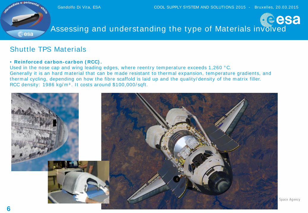
Shuttle TPS Materials • Reinforced carbon-carbon (RCC). Used in the nose cap and wing leading edges, where reentry temperature exceeds 1,260 °C. Generally it is an hard material that can be made resistant to thermal expansion, temperature gradients, and thermal cycling, depending on how the fibre scaffold is laid up and the quality/density of the matrix filler. RCC density: 1986 kg/m³. It costs around $100,000/sqft.
Gandolfo Di Vita, ESA COOL SUPPLY SYSTEM AND SOLUTIONS 2015 - Bruxelles, 20.03.2015
7
Assessing and understanding the type of Materials involved
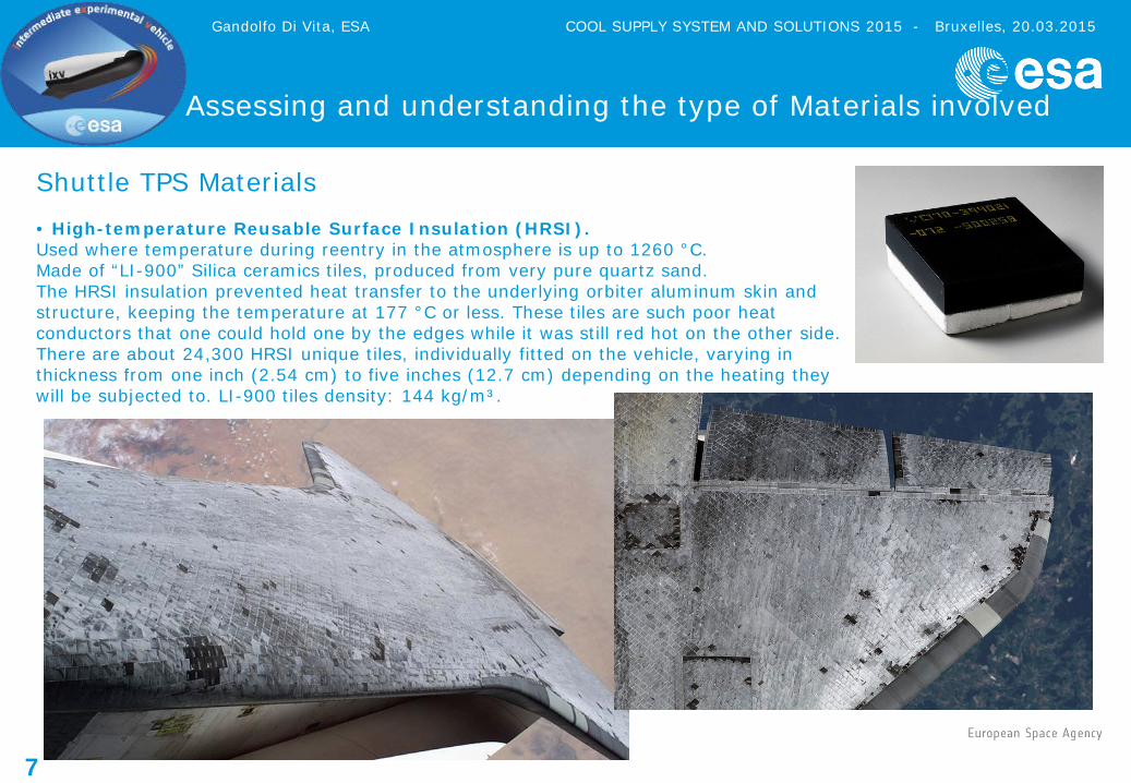
Shuttle TPS Materials • High-temperature Reusable Surface Insulation (HRSI). Used where temperature during reentry in the atmosphere is up to 1260 °C. Made of “LI-900” Silica ceramics tiles, produced from very pure quartz sand. The HRSI insulation prevented heat transfer to the underlying orbiter aluminum skin and structure, keeping the temperature at 177 °C or less. These tiles are such poor heat conductors that one could hold one by the edges while it was still red hot on the other side. There are about 24,300 HRSI unique tiles, individually fitted on the vehicle, varying in thickness from one inch (2.54 cm) to five inches (12.7 cm) depending on the heating they will be subjected to. LI-900 tiles density: 144 kg/m³.
Gandolfo Di Vita, ESA COOL SUPPLY SYSTEM AND SOLUTIONS 2015 - Bruxelles, 20.03.2015

8
Assessing and understanding the type of Materials involved
Shuttle TPS Materials • Flexible Insulation Blankets (FIB) and Advanced Flexible Reusable Surface Insulation (AFRSI). A quilted, flexible blanket-like surface insulation. Used where reentry temperature is below 650 °C. FIB blankets: 144 kg/m³
• Felt reusable surface insulation (FRSI). White Nomex felt blankets on the upper payload bay doors, portions of the midfuselage and aft fuselage sides, portions of the upper wing surface and a portion of the OMS/RCS pods. Used where temperatures stay below 370 °C. The FRSI is bonded directly to the orbiter by RTV silicon adhesive. A white-pigmented silicon elastomer coating is used to waterproof the felt and provide required thermal and optical properties. FRSI covers nearly 50 percent of the orbiter's upper surfaces.
Gandolfo Di Vita, ESA COOL SUPPLY SYSTEM AND SOLUTIONS 2015 - Bruxelles, 20.03.2015
9
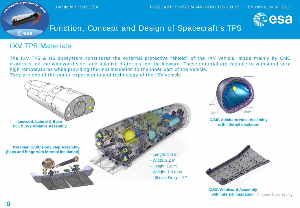
IXV TPS Materials The IXV TPS & HS subsystem constitutes the external protective “shield” of the IXV vehicle, made mainly by CMC materials, on the windward side, and ablative materials, on the leeward. These material are capable to withstand very high temperatures while providing thermal insulation to the inner part of the vehicle. They are one of the major experiments and technology of the IXV vehicle.
C/SiC Adiabatic Nose Assembly with internal insulation
Leeward, Lateral & Base P50 & SV2 Ablative Assembly
C/SiC Windward Assembly with internal insulation
- Length: 5.0 m - Width: 2.2 m - Height: 1.6 m - Weight: 1.9 tons - Lift over Drag ~ 0.7
Keraman C/SiC Body Flap Assembly (flaps and hinge with internal insulation)
Gandolfo Di Vita, ESA COOL SUPPLY SYSTEM AND SOLUTIONS 2015 - Bruxelles, 20.03.2015
Function, Concept and Design of Spacecraft's TPS

10 IXV Windward and Nose TPS
Assessing and understanding the type of Materials involved
Gandolfo Di Vita, ESA COOL SUPPLY SYSTEM AND SOLUTIONS 2015 - Bruxelles, 20.03.2015

11 IXV Body-Flaps
Assessing and understanding the type of Materials involved
Gandolfo Di Vita, ESA COOL SUPPLY SYSTEM AND SOLUTIONS 2015 - Bruxelles, 20.03.2015

12 IXV Ablative TPS on leeward, lateral and base sides
Assessing and understanding the type of Materials involved
Gandolfo Di Vita, ESA COOL SUPPLY SYSTEM AND SOLUTIONS 2015 - Bruxelles, 20.03.2015

13
Thermal Control in space applications
Thermal Control System: The Thermal Control of a space system has the function to keep all the spacecraft/system parts within acceptable temperature ranges during all mission phases, withstanding the external environment, which can vary in a wide range of temperatures as the spacecraft/system is exposed to deep space or to solar or planetary flux, and rejecting to space the internal heat dissipation of the spacecraft/system itself.
Gandolfo Di Vita, ESA COOL SUPPLY SYSTEM AND SOLUTIONS 2015 - Bruxelles, 20.03.2015
14
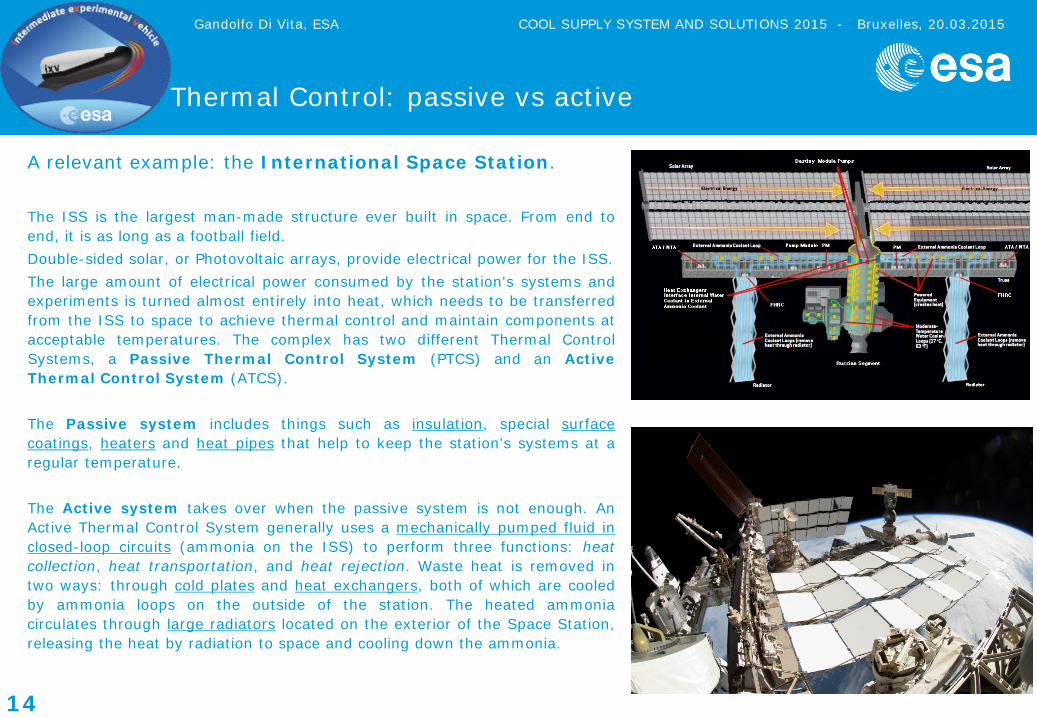
A relevant example: the International Space Station. The ISS is the largest man-made structure ever built in space. From end to end, it is as long as a football field. Double-sided solar, or Photovoltaic arrays, provide electrical power for the ISS. The large amount of electrical power consumed by the station's systems and experiments is turned almost entirely into heat, which needs to be transferred from the ISS to space to achieve thermal control and maintain components at acceptable temperatures. The complex has two different Thermal Control Systems, a Passive Thermal Control System (PTCS) and an Active Thermal Control System (ATCS). The Passive system includes things such as insulation, special surface coatings, heaters and heat pipes that help to keep the station’s systems at a regular temperature. The Active system takes over when the passive system is not enough. An Active Thermal Control System generally uses a mechanically pumped fluid in closed-loop circuits (ammonia on the ISS) to perform three functions: heat collection, heat transportation, and heat rejection. Waste heat is removed in two ways: through cold plates and heat exchangers, both of which are cooled by ammonia loops on the outside of the station. The heated ammonia circulates through large radiators located on the exterior of the Space Station, releasing the heat by radiation to space and cooling down the ammonia.
Thermal Control: passive vs active
Gandolfo Di Vita, ESA COOL SUPPLY SYSTEM AND SOLUTIONS 2015 - Bruxelles, 20.03.2015
15
Thermal Control: passive vs active
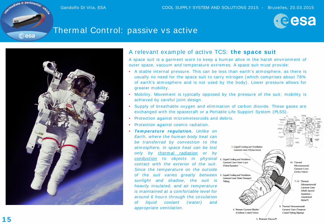
A relevant example of active TCS: the space suit A space suit is a garment worn to keep a human alive in the harsh environment of outer space, vacuum and temperature extremes. A space suit must provide: • A stable internal pressure. This can be less than earth's atmosphere, as there is
usually no need for the space suit to carry nitrogen (which comprises about 78% of earth's atmosphere and is not used by the body). Lower pressure allows for greater mobility.
• Mobility. Movement is typically opposed by the pressure of the suit; mobility is achieved by careful joint design.
• Supply of breathable oxygen and elimination of carbon dioxide. These gases are exchanged with the spacecraft or a Portable Life Support System (PLSS).
• Protection against micrometeoroids and debris. • Protection against cosmic radiation.
Gandolfo Di Vita, ESA COOL SUPPLY SYSTEM AND SOLUTIONS 2015 - Bruxelles, 20.03.2015
• Temperature regulation. Unlike on Earth, where the human body heat can be transferred by convection to the atmosphere, in space heat can be lost only by thermal radiation or by conduction to objects in physical contact with the exterior of the suit. Since the temperature on the outside of the suit varies greatly between sunlight and shadow, the suit is heavily insulated, and air temperature is maintained at a comfortable level for around 6 hours through the circulation of liquid coolant (water) and appropriate ventilation.
16
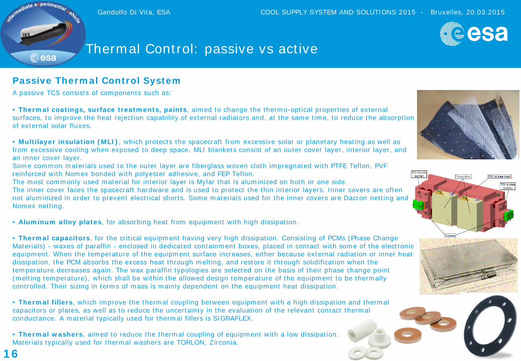
Passive Thermal Control System A passive TCS consists of components such as: • Thermal coatings, surface treatments, paints, aimed to change the thermo-optical properties of external surfaces, to improve the heat rejection capability of external radiators and, at the same time, to reduce the absorption of external solar fluxes. • Multilayer insulation (MLI), which protects the spacecraft from excessive solar or planetary heating as well as from excessive cooling when exposed to deep space. MLI blankets consist of an outer cover layer, interior layer, and an inner cover layer. Some common materials used to the outer layer are fiberglass woven cloth impregnated with PTFE Teflon, PVF reinforced with Nomex bonded with polyester adhesive, and FEP Teflon. The most commonly used material for interior layer is Mylar that is aluminized on both or one side. The inner cover faces the spacecraft hardware and is used to protect the thin interior layers. Inner covers are often not aluminized in order to prevent electrical shorts. Some materials used for the inner covers are Dacron netting and Nomex netting. • Aluminum alloy plates, for absorbing heat from equipment with high dissipation. • Thermal capacitors, for the critical equipment having very high dissipation. Consisting of PCMs (Phase Change Materials) - waxes of paraffin - enclosed in dedicated containment boxes, placed in contact with some of the electronic equipment. When the temperature of the equipment surface increases, either because external radiation or inner heat dissipation, the PCM absorbs the excess heat through melting, and restore it through solidification when the temperature decreases again. The wax paraffin typologies are selected on the basis of their phase change point (melting temperature), which shall be within the allowed design temperature of the equipment to be thermally controlled. Their sizing in terms of mass is mainly dependent on the equipment heat dissipation. • Thermal fillers, which improve the thermal coupling between equipment with a high dissipation and thermal capacitors or plates, as well as to reduce the uncertainty in the evaluation of the relevant contact thermal conductance. A material typically used for thermal fillers is SIGRAFLEX. • Thermal washers, aimed to reduce the thermal coupling of equipment with a low dissipation. Materials typically used for thermal washers are TORLON, Zirconia.
Gandolfo Di Vita, ESA COOL SUPPLY SYSTEM AND SOLUTIONS 2015 - Bruxelles, 20.03.2015
Thermal Control: passive vs active

17
A relevant example of passive TCS: the “IPOTUBA” thermal vessel (ESA study made by G. Chirulli) This thermal vessel is meant for terrestrial applications and to be used for human body tissues transportation. Tissues have to be stored at very cold temperatures (below -40 °C) to avoid their degradation during transportation for a period of time of at least 4 days.
Thermal Control: passive vs active
Gandolfo Di Vita, ESA COOL SUPPLY SYSTEM AND SOLUTIONS 2015 - Bruxelles, 20.03.2015
The considered vessel cryogenic liquid is 1-Hexanol, an organic alcohol with melting temperature of -47.4 °C. Liquid Nitrogen is used during the cool down phase to cool the system and allow 1-Hexanol to change from liquid state into solid. The thermal analysis shows that if 1-Hexanol is in solid state before starting the warming up phase, the thermal vessel design can cope with the requirement of keeping the sample stored below -40 °C for a period of time of at least four days. This is possible if the cooling phase last enough to allow the full 1-Hexanol to change state and become solid. If the cooling phase is not complete, the 1-Hexanol remains in “slush state” (it is called slush a mix of solid and liquid), then the requirement is not respected as after about 42 hours (less than 2 days) the sample compartment reaches a temperature higher than -40 °C.
18
IXV Thermal Control System
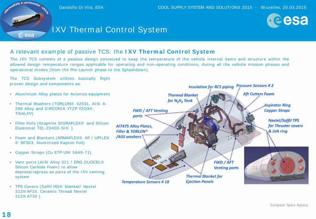
A relevant example of passive TCS: the IXV Thermal Control System The IXV TCS consists of a passive design conceived to keep the temperature of the vehicle internal items and structure within the allowed design temperature ranges applicable for operating and non-operating conditions, during all the vehicle mission phases and operational modes (from the Pre-Launch phase to the Splashdown). The TCS Subsystem utilizes basically flight proven design and components as: • Aluminium Alloy plates for Avionics equipment
• Thermal Washers (TORLON® 4203L, AISI A-
286 Alloy and ZIRCONIA YTZP Y2O3®, Ti6AL4V)
• Filler Foils (Graphite SIGRAFLEX® and Silicon Elastomer TEL-Z0400-SI® )
• Foam and Blankets (ARMAFLEX® AF / UPILEX ® BF303, Aluminized Kapton Foil)
• Copper Straps (Cu ETP UNI 5649-71)
• Vent ports (AISI Alloy 321 / ERG DUOCEL® Silicon Carbide Foam) to allow depress/repress as parts of the IXV venting system
• TPS Covers (Saffil HD® blanket/ Nextel 312®AF10, Ceramic Thread Nextel 312®AT30 )
Gandolfo Di Vita, ESA COOL SUPPLY SYSTEM AND SOLUTIONS 2015 - Bruxelles, 20.03.2015

19
IXV Mission
IXV final integration on the VEGA rocket
Gandolfo Di Vita, ESA COOL SUPPLY SYSTEM AND SOLUTIONS 2015 - Bruxelles, 20.03.2015

20
IXV Mission: successful flight on February 11th,2015
Lift-off: Kourou, French Guyana, 13:40 UTC Landing: Pacific Ocean, 15:16 UTC
Gandolfo Di Vita, ESA COOL SUPPLY SYSTEM AND SOLUTIONS 2015 - Bruxelles, 20.03.2015