spaceclaim2009plus_sp1_usersguide
DESCRIPTION
SpaceClaim2009Plus_SP1_UsersGuideTRANSCRIPT

SpaceClaim 2009+ User’s Guide
SpaceClaim 2009+ SP1
User's Guide

SpaceClaim 2009+SP1 User’s Guide
www.spaceclaim.com 2
Copy right © 2009 SpaceClaim Corporation. All Rights Reserv ed. SpaceClaim is a registered trademark of SpaceClaim Corporation.
Portions of this software Copy right © Acresso Software Inc. FlexLM and FLEXNET are trademarks of Acresso Sof tware Inc.
Portions of this software Copy right © 2008 Adobe Sy stems Incorporated. All Rights Reserv ed. Adobe and Acrobat are either registered trademarks or
trademarks of Adobe Sy stems Incorporated in the United States and/or other countries
ANSYS Workbench and GAMBIT and all other ANSYS, Inc. product names are trademarks or registered trademarks of ANSYS, Inc. or its subsidiaries
in the United States or other countries.
Contains BCLS (Bound-Constrained Least Squares) Copy right (C) 2006 Michael P. Friedlander, Department of Computer Science, Univ ersity of British
Columbia, Canada, prov ided under a LGPL 3 license which is included in the SpaceClaim installation directory (lgpl -3.0.txt). Deriv ativ e BCLS source
code av ailable upon request.
Anti-Grain Geometry Version 2.4 Copy right © 2002-2005 Maxim Shemanarev (McSeem).
Some SpaceClaim products may contain Autodesk® RealDWG by Autodesk, Inc., Copy right © 1998-2008 Autodesk, Inc. All rights reserv ed. Autodesk,
AutoCAD, and Autodesk Inv entor are registered trademarks and RealDWG is a trademark of Autodesk, Inc.
CATIA is a registered trademark of Dassault Sy stèmes.
Portions of this software Copy right © 2010 Google. SketchUp is a trademark of Google.
Portions of this software Copy right © 1999-2006 Intel Corporation. Licensed under the Apache License, Version 2.0. You may obtain a copy of the
License at http://www.apache.org/licenses/LICENSE-2.0
Contains DotNetBar licensed f rom devcomponents.com.
MatWeb is a trademark of Automation Creations, Inc.
2008 Microsof t ® Off ice Sy stem User Interf ace is licensed f rom Microsof t Corporation. Direct3D, DirectX, Microsof t PowerPoint, Excel, Windows,
Windows Vista and the Windows Vista Start button are trademarks or registered trademarks of Microsoft C orporation in the United States and/or other
countries.
Portions of this software Copy right © 2005 Nov ell, Inc. (http://www.nov ell.com)
Contains OpenDWG licensed f rom the Open Design Alliance. OpenDWG is a trademark of the Open Design Alliance.
Pro/ENGINEER and PTC are registered trademarks of Parametric Technology Corporation.
Portions of this software Copy right © 1993-2008 Robert McNeel & Associates. All Rights Reserv ed. openNURBS is a trademark of Robert McNeel & Associates.
Rhinoceros is a registered trademark of Robert McNeel & Associates.
Portions of this software Copy right © 2005-2007, Sergey Bochkanov (ALGLIB project). *
Portions of this software are owned by Siemens PLM © 1986-2009. All Rights Reserv ed. Parasolid and Unigraphics are registered trademarks and JT is a trademark of Siemens Product Lif ecycle Management Software, Inc.
SolidWorks is a registered trademark of SolidWorks Corporation.
Portions of this software are owned by Spatial Corp. © 1986-2009. All Rights Reserv ed. ACIS and SAT are registered trademarks of Spatial Corp.
Dev elopment tools and related technology prov ided under license f rom 3Dconnexion. © 1992 – 2008 3Dconnexion. All rights reserv ed.
TraceParts is owned by TraceParts S.A. TraceParts is a registered trademark of TraceParts S.A.
Contains a modif ied v ersion of source av ailable f rom Unicode, Inc., copy right © 1991-2008 Unicode, Inc. All rights reserv ed. Distributed under the
Terms of Use in http://www.unicode.org/copy right.html.
Portions of this software Copy right © 1992-2008 The Univ ersity of Tennessee. All rights reserv ed. *
Portions of this software Copy right © XHEO INC. All Rights Reserv ed. Deploy LX is a trademark of XHEO INC.
All other trademarks, trade names or company names ref erenced in SpaceClaim software, documentation and promotional materials are used f or
identif ication only and are the property of their respectiv e owners.
* Additional notice f or LAPACK and ALGLIB
Redistribution and use in source and binary f orms, with or without modif ication, are permitted prov ided that the f ollowing conditions are met:
- Redistributions of source code must retain the abov e copy right notice, this list of conditions and the f ollowing disclaimer.
- Redistributions in binary form must reproduce the abov e copy right notice, this list of conditions and the f ollowing disclaimer listed in this license in the
documentation and/or other materials prov ided with the distribution.
- Neither the name of the copy right holders nor the names of its contributors may be used to endorse or prom ote products deriv ed f rom this sof tware
without specif ic prior written permission.
THIS SOFTWARE IS PROVIDED BY THE COPYRIGHT HOLDERS AND CONTRIBUTORS "AS IS" AND ANY EXPRESS OR IMPLIED
WARRANTIES, INCLUDING, BUT NOT LIMITED TO, THE IMPLIED WARRANTIES OF MERCHANTABILITY AND FITNESS FOR A PARTICULAR
PURPOSE ARE DISCLAIMED. IN NO EVENT SHALL THE COPYRIGHT OWNER OR CONTRIBUTORS BE LIABLE FOR ANY DIRECT, INDIRECT,
INCIDENTAL, SPECIAL, EXEMPLARY, OR CONSEQUENTIAL DAMAGES (INCLUDING, BUT NOT LIMITED TO, PROCUREMENT OF SUBSTITU TE GOODS OR SERVICES; LOSS OF USE, DATA, OR PROFITS; OR BUSINESS INTERRUPTION) HOWEVER CAUSED AND ON
ANY THEORY OF LIABILITY, WHETHER IN CONTRACT, STRICT LIABILITY, OR TORT (INCLUDING NEGLIGENCE OR OTHERWISE) ARISING IN
ANY WAY OUT OF THE USE OF THIS SOFTWARE, EVEN IF ADVISED OF THE POSSIBILITY OF SUCH DAMAGE.
SpaceClaim 2009+SP1 User’s Guide
www.spaceclaim.com 3
Contents
Introduction ....................................................................................................................................12
Tutorials........................................................................................................................................12
Bracket and knob tutorial ...............................................................................................................13
Converting a solid to a sheet metal part tutorial ...............................................................................38
SpaceClaim objects ........................................................................................................................45
Working with components ..............................................................................................................46
Internal, external, and independent components ..............................................................................48
Lightweight components ................................................................................................................50
The SpaceClaim interface ...............................................................................................................51
Structure tree ................................................................................................................................52
Selection panel ..............................................................................................................................54
Working with layers .......................................................................................................................58
Working with groups ......................................................................................................................59
Working with views ........................................................................................................................61
Status bar .....................................................................................................................................62
Options panel ................................................................................................................................62
Properties panel ............................................................................................................................63
Keyboard shortcuts........................................................................................................................66
Using a multitouch screen ..............................................................................................................69
Mouse and touch gestures .............................................................................................................74
Using the radial menu ....................................................................................................................75
Selecting .........................................................................................................................................77
Selecting by drawing a box.............................................................................................................81
Selecting by drawing a freeform shape (lasso) .................................................................................84
Selecting by painting......................................................................................................................86
Designing........................................................................................................................................88
Design modes ...............................................................................................................................88
Editing in cross-section ..................................................................................................................89
Cutting, copying, and pasting .........................................................................................................91
Dimensions ...................................................................................................................................92
Detaching .....................................................................................................................................95
Undo and redo ..............................................................................................................................95
Checking geometry ........................................................................................................................96
Locking and unlocking objects ........................................................................................................96

SpaceClaim 2009+SP1 User’s Guide
www.spaceclaim.com 4
Sketching........................................................................................................................................98
Editing a sketch ........................................................................................................................... 101
Copying a sketch ......................................................................................................................... 104
The sketch grid............................................................................................................................ 104
Moving the sketch grid ................................................................................................................. 105
Sketch layouts............................................................................................................................. 106
Moving in two dimensions ............................................................................................................ 107
Dimensional sketching ................................................................................................................. 108
Points ......................................................................................................................................... 108
Lines .......................................................................................................................................... 108
Tangent lines .............................................................................................................................. 109
Construction lines ........................................................................................................................ 110
Rectangles .................................................................................................................................. 110
Three-point rectangles ................................................................................................................. 111
Circles ........................................................................................................................................ 111
Three-point circles ....................................................................................................................... 112
Construction circles ..................................................................................................................... 113
Ellipses ....................................................................................................................................... 114
Tangent arcs ............................................................................................................................... 114
Swept arcs .................................................................................................................................. 115
Three-point arcs .......................................................................................................................... 116
Polygons ..................................................................................................................................... 116
Creating a spline ......................................................................................................................... 118
Editing a spline ............................................................................................................................ 119
Splitting lines ............................................................................................................................... 121
Trimming lines ............................................................................................................................. 121
Creating corners .......................................................................................................................... 121
Creating rounded corners............................................................................................................. 122
Offsetting lines ............................................................................................................................ 123
Projecting onto the sketch grid...................................................................................................... 124
Bending ...................................................................................................................................... 125
Scaling sketches ......................................................................................................................... 126
Scaling sketches with Pull ............................................................................................................ 127
Editing .......................................................................................................................................... 129
Pulling........................................................................................................................................... 130

SpaceClaim 2009+SP1 User’s Guide
www.spaceclaim.com 5
Offsetting or extruding faces ......................................................................................................... 136
Extending or extruding surface edges ........................................................................................... 138
Rounding edges .......................................................................................................................... 140
Rounding between faces and surfaces .......................................................................................... 144
Chamfering edges ....................................................................................................................... 146
Extruding edges .......................................................................................................................... 149
Pivoting edges ............................................................................................................................ 150
Revolving faces ........................................................................................................................... 151
Revolving edges .......................................................................................................................... 153
Revolving helices ........................................................................................................................ 155
Sweeping.................................................................................................................................... 157
Sweeping with multiple trajectories ............................................................................................... 160
Sweeping with an axis ................................................................................................................. 163
Drafting faces .............................................................................................................................. 164
Blending between faces ............................................................................................................... 166
Blending between edges .............................................................................................................. 170
Blending between points .............................................................................................................. 172
Creating slots .............................................................................................................................. 174
Scaling solids and surfaces .......................................................................................................... 177
Copying edges and faces ............................................................................................................. 179
Pulling with the Select tool ........................................................................................................... 180
Pivoting with the Select tool.......................................................................................................... 181
Moving .......................................................................................................................................... 182
The Move handle......................................................................................................................... 186
Creating patterns ......................................................................................................................... 187
Exploding an assembly ................................................................................................................ 194
Pivoting and pulling solids ............................................................................................................ 194
Moving with the Select tool ........................................................................................................... 195
Moving with the Fulcrum tool guide ............................................................................................... 196
Moving protrusions and depressions ............................................................................................. 197
Driving modification with annotation dimensions ............................................................................ 197
Filling ............................................................................................................................................ 201
Removing rounds ........................................................................................................................ 213
Tweaking a face ............................................................................................................................ 217
Tweak face editing methods ......................................................................................................... 218

SpaceClaim 2009+SP1 User’s Guide
www.spaceclaim.com 6
Add a control curve...................................................................................................................... 219
Show grid, curvature, or comb ...................................................................................................... 219
Replacing faces ............................................................................................................................ 220
Intersecting................................................................................................................................... 222
Combining and splitting ............................................................................................................... 223
Merging solids and surfaces ......................................................................................................... 225
Merging solids ............................................................................................................................. 226
Merging surface protrusions ......................................................................................................... 226
Merging surfaces ......................................................................................................................... 226
Capping a surface with a plane..................................................................................................... 228
Splitting solids and surfaces ......................................................................................................... 228
Splitting a solid with a surface, plane, or another solid .................................................................... 230
Using the Split Solid tool .............................................................................................................. 230
Splitting a face ............................................................................................................................ 232
Splitting a surface ........................................................................................................................ 235
Removing material from a solid .................................................................................................... 235
Projecting to a solid ..................................................................................................................... 236
Inserting........................................................................................................................................ 238
Inserting another design............................................................................................................... 238
Inserting an image ....................................................................................................................... 239
Inserting a video .......................................................................................................................... 241
Inserting a plane.......................................................................................................................... 242
Inserting an axis .......................................................................................................................... 244
Inserting an origin ........................................................................................................................ 245
Creating a cylinder....................................................................................................................... 246
Creating a sphere ........................................................................................................................ 247
Shelling a solid ............................................................................................................................ 249
Creating an offset relationship ...................................................................................................... 250
Inserting a face curve .................................................................................................................. 251
Creating mirror relationships ........................................................................................................ 252
Mirroring a solid, surface, or face .................................................................................................. 253
Set up a mirror relationship between two faces .............................................................................. 254
Remove a mirror face or plane ..................................................................................................... 254
Find similar faces on the other side of a mirror ............................................................................... 254
Inserting temporary points, axes, and planes ................................................................................. 255

SpaceClaim 2009+SP1 User’s Guide
www.spaceclaim.com 7
Assembling components .............................................................................................................. 260
Aligning components ................................................................................................................... 261
Aligning axes............................................................................................................................... 262
Orienting components .................................................................................................................. 262
Detailing........................................................................................................................................ 264
Annotation .................................................................................................................................. 264
Creating notes ............................................................................................................................. 265
Formatting note text ..................................................................................................................... 266
Creating note leaders .................................................................................................................. 267
Creating dimension annotations ................................................................................................... 269
Dimension between virtual points ................................................................................................. 273
Creating geometric tolerance annotations ..................................................................................... 277
Datum and surface finish symbols ................................................................................................ 278
Surface finish symbols ................................................................................................................. 278
Center marks and lines ................................................................................................................ 279
Threads ...................................................................................................................................... 280
Bills of Materials (BOMs).............................................................................................................. 281
Tables ........................................................................................................................................ 284
Balloon ....................................................................................................................................... 285
Drawing sheets ........................................................................................................................... 286
Setting up a drawing sheet ........................................................................................................... 288
Formatting a drawing sheet .......................................................................................................... 288
Working with views ...................................................................................................................... 289
Projected views ........................................................................................................................... 290
Cross-section views ..................................................................................................................... 292
Detail views ................................................................................................................................. 294
3D markup .................................................................................................................................. 294
Creating 3D markup slides ........................................................................................................... 296
Displaying changed dimensions ................................................................................................... 296
Coloring changed faces ............................................................................................................... 297
Setting detailing options ............................................................................................................... 297
Displaying your design ................................................................................................................. 302
Showing and hiding objects .......................................................................................................... 302
Orienting designs ......................................................................................................................... 303
Spinning your design ................................................................................................................... 303

SpaceClaim 2009+SP1 User’s Guide
www.spaceclaim.com 8
Panning your design .................................................................................................................... 304
Zooming in and out ...................................................................................................................... 305
Rotating your design .................................................................................................................... 305
The Home view ........................................................................................................................... 306
Display a head-on view of the sketch grid...................................................................................... 306
Selecting a view .......................................................................................................................... 306
Snapping to a view ...................................................................................................................... 307
Applying a graphics style ............................................................................................................. 309
Displaying edges ......................................................................................................................... 309
Applying colors ............................................................................................................................ 310
Line styles................................................................................................................................... 312
Displaying your design in multiple windows ................................................................................... 312
Splitting the workspace window .................................................................................................... 312
Switching between windows in the workspace ............................................................................... 313
Maximizing the Design window ..................................................................................................... 313
Displaying workspace tools .......................................................................................................... 313
Sketch grid styles ........................................................................................................................ 314
Displaying lightweight components ............................................................................................... 316
Measuring and analyzing .............................................................................................................. 317
Checking clearance ..................................................................................................................... 317
Displaying interference ................................................................................................................ 317
Measuring ................................................................................................................................... 318
Displaying mass .......................................................................................................................... 319
Displaying measurements ............................................................................................................ 319
Measure a projected area ............................................................................................................ 321
Analyzing quality ......................................................................................................................... 322
Displaying normal direction .......................................................................................................... 322
Displaying curvature .................................................................................................................... 323
Displaying draft angles ................................................................................................................. 324
Displaying a face (UV) grid........................................................................................................... 326
Displaying a dihedral graph .......................................................................................................... 327
Displaying stripes ........................................................................................................................ 328
Repairing problems ...................................................................................................................... 330
Navigate through issues............................................................................................................... 330
Repair gaps ................................................................................................................................ 330

SpaceClaim 2009+SP1 User’s Guide
www.spaceclaim.com 9
Find and correct missing faces ..................................................................................................... 332
Repair split edges ........................................................................................................................ 333
Repair inexact edges ................................................................................................................... 334
Stitch adjacent faces .................................................................................................................... 335
Merge faces ................................................................................................................................ 336
Simplify a design ......................................................................................................................... 337
Remove small faces .................................................................................................................... 338
Adjust tangency........................................................................................................................... 340
Preparing designs for analysis ..................................................................................................... 342
Extracting volume ........................................................................................................................ 342
Creating midsurface faces ............................................................................................................ 343
Defining weld points..................................................................................................................... 346
Creating enclosures ..................................................................................................................... 349
Splitting by plane ......................................................................................................................... 351
Extend adjacent faces.................................................................................................................. 352
Imprinting.................................................................................................................................... 354
Remove rounds ........................................................................................................................... 355
Remove faces ............................................................................................................................. 356
Remove interference ................................................................................................................... 356
Beams ........................................................................................................................................ 357
Creating a beam.......................................................................................................................... 360
Extracting a beam from a solid ..................................................................................................... 360
Beam properties .......................................................................................................................... 361
Changing beam profiles ............................................................................................................... 362
Changing beam orientation .......................................................................................................... 363
Moving beams ............................................................................................................................. 365
Changing beam display style........................................................................................................ 366
Creating a new beam profile......................................................................................................... 366
Creating, opening, and saving documents ................................................................................... 367
Importing and exporting ............................................................................................................... 368
Copying and pasting from other applications ................................................................................. 376
Printing drawing sheets and designs ............................................................................................. 376
Journals and logs ........................................................................................................................ 378
SpaceClaim file format ................................................................................................................. 379
Customizing SpaceClaim .............................................................................................................. 382

SpaceClaim 2009+SP1 User’s Guide
www.spaceclaim.com 10
Popular options ........................................................................................................................... 382
File import and export options ...................................................................................................... 385
Appearance options ..................................................................................................................... 389
Snap options ............................................................................................................................... 389
Units options ............................................................................................................................... 392
Support file options ...................................................................................................................... 393
Sheet Metal options ..................................................................................................................... 393
Advanced options ........................................................................................................................ 395
Quick Access toolbar options ....................................................................................................... 397
Navigation options ....................................................................................................................... 398
Configuring windows .................................................................................................................... 399
Customizing the Welcome window................................................................................................ 399
Working with sheet metal ............................................................................................................. 403
Creating a sheet metal design ...................................................................................................... 403
Editing a sheet metal design ........................................................................................................ 405
Creating and changing bend reliefs ............................................................................................... 405
Changing junctions ...................................................................................................................... 406
Making watertight corners ............................................................................................................ 407
Changing bend behavior options .................................................................................................. 408
Create bends from sketch curves ................................................................................................. 408
Creating jogs and hems ............................................................................................................... 410
Moving walls relative to other walls ............................................................................................... 411
Rotating walls .............................................................................................................................. 411
Creating walls between bodies ..................................................................................................... 413
Changing sheet metal part properties............................................................................................ 413
Converting a design to sheet metal ............................................................................................... 414
Unfolding sheet metal components ............................................................................................... 416
Calculating unfolded lengths ........................................................................................................ 418
Correcting a sheet metal component ............................................................................................. 418
SpaceClaim add-ins..................................................................................................................... 420
SpaceClaim API .......................................................................................................................... 420
ANSYS add-in ............................................................................................................................. 421
ANSYS demos and tutorials.......................................................................................................... 422
Spot welds tutorial ....................................................................................................................... 422
Midsurface tutorial ....................................................................................................................... 431

SpaceClaim 2009+SP1 User’s Guide
www.spaceclaim.com 11
Shared topology tutorial ............................................................................................................... 441
Using groups and dimensions in ANSYS tutorial ............................................................................ 447
SpaceClaim parts and properties in ANSYS .................................................................................. 454
Using groups to drive changes in ANSYS...................................................................................... 455
Using named selections in ANSYS ............................................................................................... 456
Shared topology in ANSYS .......................................................................................................... 456
ANSYS Workbench settings ......................................................................................................... 457
Configuring SpaceClaim and ANSYS 12 and 12.1 ......................................................................... 459
Connecting to ANSYS 12 and 12.1 ............................................................................................... 460
Updating data with ANSYS 12 and 12.1 ........................................................................................ 460
Configuring SpaceClaim and ANSYS 11 ....................................................................................... 461
Connecting to ANSYS 11 ............................................................................................................. 461
Updating data with ANSYS 11 ...................................................................................................... 461
Glossary ....................................................................................................................................... 463

SpaceClaim 2009+SP1 User’s Guide
www.spaceclaim.com 12
Introduction SpaceClaim 2009+ is the 3D productivity tool for engineers who need to focus on their core competencies
while also benefiting from working in 3D. The software provides a highly flexible design environment coupled with a modern user experience that speeds contributions to the product development process. SpaceClaim is for those who collaborate in the design and manufacture of mechanical products
across a broad range of industries.
The online help, tutorials, and training materials are provided to help you become productive with SpaceClaim as quickly as possible. We strongly recommend that you review the Getting Started section
and step through the tutorials provided in the online help before beginning your own work.
User's Guide
This User's Guide begins with a focus on the basic tools and on simple concepts. SpaceClaim is all about adding and manipulating the faces of a design model, primarily through pull and move operations . If there
is a face, you can pull on it. If you need a new face, draw an edge or copy an existing one. Design clutter is minimized wherever possible. This guide communicates these simple, but powerful concepts so that you can extrapolate them to your real -world designs. This guide also provides useful shortcuts to use as
you progress, as well as animations of tools in action to help you understand their function.
SpaceClaim is different, and we encourage you to open your mind and enter into a world where y ou can focus on the design, not the software. SpaceClaim appreciates your feedback, so let us know where we
have succeeded and what we can do better. Thanks for your purchase and we look forward to working with you!
Tutorials
Tutorials and demos are available on the SpaceClaim web site. Step-by-step tutorials are also available in this Help file. Working through each of the tutorials will allow you to quickly grasp the basics of using SpaceClaim. We strongly recommend that newcomers to 3D design run through the tutorials. You will
gain competency with the functionality featured and the experience will help you master the remaining features more easily.
Text tutorials
The following tutorials are available in this Help file:
Bracket and knob
In this tutorial, you will
Create a bracket using SpaceClaim's sketching and 3D editing tools.
Create an assembly by importing and modifying a knob to fit into your bracket.
Create a drawing sheet to detail your design.
Sheet Metal
In this tutorial, you will
Create and shell a simple solid.
Use the selection filter and power selection.
Add corner reliefs to a sheet metal part.
Convert edges to sheet metal bends and
junctions.
Create rips in the part so it can be unfolded.
Unfold a sheet metal part.

SpaceClaim 2009+SP1 User’s Guide
www.spaceclaim.com 13
Self-paced training tutorials
Self-paced, animated training tutorials are available on MySpaceClaim.com, a personalized web portal for easy access to everything SpaceClaim. On MySpaceClaim.com, you can:
Gain access through a unique user name and password
Directly download SpaceClaim software, including purchased new products, updates, and upgrades
Learn from self-paced training tutorials
Submit a new idea
To access MySpaceClaim.com, select the Login link at the top of the SpaceClaim.com home page.
Bracket and knob tutorial
In this tutorial, you will:
Create a bracket using SpaceClaim's sketching and 3D editing tools
Create an assembly by importing and modifying a knob to fit into your bracket
Create a drawing sheet to detail your design
This tutorial illustrates many of the tools and their capabilities by showing just one method of creating
geometry. In SpaceClaim, there are several other ways to create identical geometry.
Please note that as you move back and forth between windows, you may need to click in the SpaceClaim window to activate it.
The tutorial should take about an hour to complete.
Bracket and knob tutorial: Step 1
Create a new design document
1. Select New > New Design from the Application menu to create a new design.
A blank design containing the sketch grid is displayed in a new Design window. The mode is set to Sketch, since that is usually the first step to create a new design.
The following figure shows some of the interface elements referred to in this tutorial.

SpaceClaim 2009+SP1 User’s Guide
www.spaceclaim.com 14
2. Select Save from the Application menu to name and save your design.
The name of your design appears as the top-level component in the Structure tree.
Bracket and knob tutorial: Step 2
Spin, pan, and zoom
1. Experiment with the various methods for orienting the view:
Use the middle mouse button. (Drag the middle mouse button to spin, Shift+drag to pan,
and Ctrl+drag it to zoom based on cursor position.)
Use the Spin, Pan, and Zoom tools in the Orient ribbon group.
Use the Spin, Pan, and Zoom tools at the bottom right of the SpaceClaim window.
Use a Spaceball (optional).
2. Click Home in the Orient ribbon group or press the H key to restore the original view.
Bracket and knob tutorial: Step 3
Set your design preferences
1. Click SpaceClaim Options in the Application menu .
2. Click Units.

SpaceClaim 2009+SP1 User’s Guide
www.spaceclaim.com 15
3. Select Imperial from the Type drop-down.
Inches appear in the Length drop-down, the minor grid spacing changes from .1mm to 1/8 in, and
the minor grid lines per major changes from 10 to 8. This means that you can dimension in inches, and that the sketch grid lines are now spaced 1/8 inch apart, and the darker grid lines appear every inch.
4. Select Decimal from the Decimal/fraction drop-down.
5. Click OK.
Bracket and knob tutorial: Step 4
Create the bottom of the bracket
1. Sketch a rectangle that will become the bottom piece of the bracket.
a.
b. Click the Rectangle tool in the Sketch ribbon group on the Design tab.
The grid indicates that you are in Sketch mode.
Note that pressing the K key is a shortcut for quickly returning to Sketch mode.
c. Click to set the first corner of the rectangle. (Start at the upper left.)
As you move your mouse, a preview of the rectangle is drawn, and dimension fields
appear.
d. Type 1.125, then press Tab and dimension the second side by typing 4.281.
e. Press Enter to complete the rectangle.
Note: If you make a mistake, click a dimension to edit it, or click the Select tool in the Edit ribbon group and double-click the rectangle to select it. Then press Delete to delete
the rectangle and redraw it. You can also use Ctrl+Z and Ctrl+Y to undo and redo steps .
2. Pull the rectangle into 3D to create the bottom of the bracket.
a. Switch to 3D mode by clicking the 3D mode tool in the Mode ribbon group.
You can also use the D key to quickly enter 3D mode.
The Pull tool in the Edit ribbon group is activated, your sketched rectangle now appears as a rectangular surface, and the surface appears in the Structure tree.
b. Click on the rectangular surface to select it.

SpaceClaim 2009+SP1 User’s Guide
www.spaceclaim.com 16
The faint yellow cursor arrows show you the directions in which you can pull the rectangle.
c. Drag to begin adding thickness to the rectangle.
You can drag with your cursor anywhere in the Design window—you do not have to drag on the Pull arrow itself. We recommend that you move your mouse off to the side when pulling to make it easier to see your changes.
d. Type .483 and press Enter.
The surface in the Structure tree becomes a solid. (Pulling a curve creates a surface, while pulling a surface creates a solid.)
3. Press Ctrl+S or select Save from the Application menu to save your design.
Bracket and knob tutorial: Step 5
Create the back of the bracket
1. Extrude an edge to form a surface.
a. Click the back edge of the solid with the Pull tool to select it.
The edge is highlighted and edge options appear in the Options panel and mini -toolbar. Move your mouse closer to the mini-toolbar to make it more opaque.
If you moved the model in the Design window, click the Home button in the Orient group on the Design tab. You can also press H. This orients the model to its default view and sizes it to fit inside the Design window, as shown in the images.

SpaceClaim 2009+SP1 User’s Guide
www.spaceclaim.com 17
b. Select the extrude edge option in the Options panel.
(You can hover over any option to display a tooltip that explains the option.)
The Pull arrows change to indicate the two default directions in which you can extrude
the edge.
c. Drag the edge upward to begin creating a surface.
d. While dragging, press and release the spacebar to display a dimension field.
You can press the spacebar to edit a dimension whenever a dimension is displayed.
e. Type 1.4.
f. Press Enter to complete the surface.
This surface now appears in the structure tree, below the solid.
2. Pull the surface into a solid.
a. Click the surface you just created and drag toward the front of the solid as shown below.
b. Enter .483 to match the thickness of your first solid.

SpaceClaim 2009+SP1 User’s Guide
www.spaceclaim.com 18
c. Press Enter to finish pulling and create the surface.
In the Structure tree, the surface disappears and this new solid is automatically merged
with the first.
3. Save your work.
Bracket and knob tutorial: Step 6
Round the corners
1. Round the inside corner of the bracket.
a. Click the edge on the inside corner of the bracket with the Pull tool.
b. Select the Round Edge pull option in the mini-toolbar and the Options panel.
c. Drag in the direction of the arrow to round the edge.
d. While dragging, press and release the spacebar to display a dimension field.

SpaceClaim 2009+SP1 User’s Guide
www.spaceclaim.com 19
e. Type .2 and press Enter.
2. Round the outside corner of the bracket.
a. Turn the bracket so you can see the bottom by clicking the Spin tool in the Orient ribbon group and dragging to spin your design.
Another way to spin is to mouse over an edge in your design, then press Alt and drag with the middle mouse button to spin your design around that edge.(Release the Alt key after you start spinning the model.) Spinning in this way lets you keep the current tool
active.
b. Repeat the previous steps to create a 0.4" round on the outer edge, as shown below.
c. Click Home in the Orient ribbon group to return the design to trimetric view.
3. Save your work.
Bracket and knob tutorial: Step 7
Taper the end of the bracket (Part 1)
1. Sketch a dimensioned point on the top face of the long arm of the bracket, as shown in the figure.
a. Click the Select tool in the Edit ribbon group and select the top face of the bottom
piece of the bracket.
Note that pressing the Esc key several times returns you to the Select tool.
b. Click the Point tool in the Sketch ribbon group.
You are now in Sketch mode. The sketch grid appears and the Sketch mode tool is
active in the Mode ribbon group. Because you entered Sketch mode with a face selected, SpaceClaim assumes you want to sketch on that face, and orients the sketch grid along that face.

SpaceClaim 2009+SP1 User’s Guide
www.spaceclaim.com 20
c. Click Plan View in the Orient ribbon or the mini-toolbar to view the sketch grid head-on.
d. Place the cursor over the bottom right vertex of the face (as shown below) and press and release Shift, then move your mouse toward the back of the bracket along the right edge without pressing any mouse button. A dimension field appears.
This method (often called "Shift+touch" dimensioning) allows any object in any tool to dimension from that referenced object.
e. Press and release the spacebar to dimension the point’s distance from the vertex (1.5"
along the edge).
Press Tab if you need to switch dimension fields.
f. Press Enter to create the point.
If the point was created at the wrong place, you can press Ctrl+Z or click in the Quick
Access toolbar (on the left side of the SpaceClaim title bar) to try again.
2. Draw an angled line.
a. Click the Line tool in the Sketch ribbon group.
You can use the L key as a shortcut to the Line tool.
b. Click the point you created in the previous step (a small green ball appears when the cursor is over the point) and then move the cursor to create a line similar to the image
(edges will highlight when the cursor is over them to indicate coincidence).
Two dimensions appear, one for the line's length and one for the angle formed between the sketch grid and the line.

SpaceClaim 2009+SP1 User’s Guide
www.spaceclaim.com 21
c. Press and release the spacebar to dimension the line. Using the Tab key, switch to the angle dimension and type 103 to change the angle of the line.
d. Press the Esc key to end line creation.
You can also right-click and select Finish Line.
3. Remove material from the bracket.
a. Go to Home view and press P to enter the Pull tool.
You are now back in 3D mode. The 3D mode tool is active in the Mode ribbon group.
b. Click the triangular region created by the line and the edge of the bracket.
Note that the line effectively splits the original surface into two surfaces.
c. Drag downward until all the material is removed.
Note that as you pull, the Pull tool assumes that you want to remove material, and the
cursor changes to indicate that the pull is subtractive. If you pull in the opposite
direction, material will be added.
4. Save your work.
Bracket and knob tutorial: Step 8
Taper the end of the bracket (Part 2)
1. Copy the existing edge to use as a pivot axis.

SpaceClaim 2009+SP1 User’s Guide
www.spaceclaim.com 22
a. Use the Views drop-down menu to select the Isometric view, then rotate the model to view the other side (see figure).
b. Select the bottom left edge of the bracket, as shown below.
c. In the Options panel or the mini -toolbar, select the Copy Edge option.
Two arrows appear to indicate the directions the edge can be copied along existing
surfaces. You can Tab between the directions.
d. Drag the edge along the surface 1.5".
2. Revolve the face to match the angled face on the other side of the bracket.
a. Select the newly created surface between the new line and the end of the bracket.
b. Click the Revolve tool guide (located on the right side of the Design window).

SpaceClaim 2009+SP1 User’s Guide
www.spaceclaim.com 23
c. Click the line created in the previous step.
The line is highlighted in blue and the Pull arrow changes to show that pulling will revolve
the selected face.
d. Drag to begin revolving the face. While dragging, press and release the spacebar to dimension the revolve.
e. Enter -13 and press Enter to finish the revolve.
3. Save your work.
Bracket and knob tutorial: Step 9
Round the tapered end
1. Clear your previous selections by clicking in white space in the Design window.
This method ensures that you stay within the same tool (Pull in this example).
2. Select one of the edges at the end of the bracket and Ctrl+click the other edge to add it to your selection.
3. Click the Round option in the Options panel or the mini-toolbar.

SpaceClaim 2009+SP1 User’s Guide
www.spaceclaim.com 24
4. Create a full round on the end of the bracket:
a. Drag in the direction of the arrow until both edges are slightly rounded.
b. Slowly pull the mouse back as if you were removing the round.
c. Keep going until the end is fully rounded.
5. Save your work.
Bracket and knob tutorial: Step 10
Create a hole
1. Create a circle at the end of the bracket.
a. Click the Circle tool in the Sketch ribbon group and then click the top surface of the
long arm of the bracket.
b. Click Plan View in the Orient ribbon group or the Plan View icon in the toolbar at the
bottom of the grid to view the sketch grid head-on.
c. The center of the arc created by the full round is shown with a cross.
d. Click the center of the arc and move the cursor to begin sketching a circle, then use the spacebar to dimension the diameter to 0.3".
2. Pull the circle to create a hole in the end of the bracket.
a. Click the Pull tool in the Edit ribbon group and go to Home view.

SpaceClaim 2009+SP1 User’s Guide
www.spaceclaim.com 25
b. Select the circular region and drag downward until all the material is removed.
c. Drag with the middle mouse button to spin the bracket so you can see through the hole.
3. Save your work.
Bracket and knob tutorial: Step 11
Create a second hole
1. Copy the existing hole.
a. Select the cylindrical inner surface of the hole.
b. Click the Move tool from the Edit ribbon group.
c. While holding down the Ctrl key, select and drag the arrow (vector) in the Move handle.
The hole is copied along the arm of the bracket. You can see previews of the hole as
long as the geometry is valid.
d. Stop dragging anywhere to complete the copy.
2. Position the hole accurately.

SpaceClaim 2009+SP1 User’s Guide
www.spaceclaim.com 26
a. Click on the same arrow or vector in the Move handle.
b. In the small toolbar that appears, click the Ruler Dimension tool.
A dimension will appear and snap to geometry as you hover over various entities.
c. Select the point created earlier or either of the edges that are coincident with it.
The dimension freezes and waits for a new value to be entered.
d. Enter a value of zero to align the axis of the hole with these edges.
You can also offset selected geometry from a reference by entering a value using the
same method.
3. Increase the size of the hole.
a. Press P to select the Pull tool and select the cylindrical surface of the hole.
b. Drag in the opposite direction of the arrow to increase the size of the hole to a dimension of your choice.
c. Use Ctrl+Z to undo the previous operation and return the hole to its original size. If you
go too far, use Ctrl+Y to redo steps.
4. Save your work.

SpaceClaim 2009+SP1 User’s Guide
www.spaceclaim.com 27
Bracket and knob tutorial: Step 12
Create a pattern of holes
1. Create a pattern with the Move tool.
a. Press M to select the Move tool.
b. Check the Create Patterns option in the Options panel.
c. Zoom into your design by selecting Zoom Extents from the Zoom tool menu to make the
next step easier.
d. Click the inner cylindrical surface of the hole that you just created.
e. Press and hold the Ctrl key while dragging the Move handle along the long axis of the
bracket a distance of 1.7".
You can release the Ctrl key after you begin dragging.
A pattern count parameter is displayed, along with the dimension from the original hole to
the copied hole.
2. Edit the pattern.
a. Use the Tab key to highlight the count entry and enter a value of 4.
Four identical, equidistant holes appear on the bracket surface. These holes are now part of a pattern. The dimension between each hole in the pattern is now displayed as w ell as the other parameters.
b. Select the Pull tool and select an axis of one of your holes.

SpaceClaim 2009+SP1 User’s Guide
www.spaceclaim.com 28
c. Drag to change the holes to slots.
Notice that changes made to one hole affect all the others in the pattern.
d. Press Ctrl+Z to undo your change.
3. Save your work.
Bracket and knob tutorial: Step 13
Chamfer the top edge
1. Chamfer the top edge using the Pull tool.
a. Click the Pull tool in the Edit ribbon group.
b. Double-click one of the top edges to select the edge loop.
Note that double-clicking the same edge multiple times shows you each edge loop set the edge is part of. If the wrong edge loop is selected, double -click to select an alternate
loop.
c. Select the chamfer edge option in the Options panel or the mini-toolbar.
d. Drag in the direction of the arrow to begin chamfering the edge.

SpaceClaim 2009+SP1 User’s Guide
www.spaceclaim.com 29
Note that chamfers are 45 degrees by default, but you can change the distance of each side.
e. While dragging, use the spacebar to enter a value of 0.1" for the chamfer’s setback.
f. Press Enter to finish pulling and create the chamfered edges.
2. Save your work.
Bracket and knob tutorial: Step 14
Import the knob
1. Get the knob model.
a. Select SpaceClaim Options from the Application menu .
b. Click Resources.
c. Click Get Models to display the SpaceClaim Model Library on the SpaceClaim web site.
d. Find the TutorialKnob.scdoc file and click Download.
e. Press Cancel to close the SpaceClaim Options dialog box.
2. Insert the knob component.
a. Click Home to orient your bracket.
b. Click the Insert tool in the Insert ribbon group to display the Open Design window.
c. Navigate to and select TutorialKnob.scdoc and click Open.
The knob appears in the Design window inside the outline of an orange box with the Move tool active to move it to a better position.
3. Move the knob so its small end is pointing at the back of the bracket.
a. Drag on one of the Move handle arrows (vectors) to separate the solids and make them easier to work with.
b. Drag on the curved Move handle arrows (vectors) to approximately point the small end of the handle towards the back of the bracket.
4. Create and activate a component for the bracket.
a. In the Structure panel, right-click the bracket (named Solid) select Move to New Component.
A new component, Component1, appears in the structure tree and it contains the
bracket solid.
Its name is highlighted so you can rename it immediately after it is created.
b. Rename the new component to Bracket.
c. In the Structure panel, right-click Design1 and select Activate Component.

SpaceClaim 2009+SP1 User’s Guide
www.spaceclaim.com 30
The active component is displayed in bold in the Structure panel.
Activating components allows you to select whether you are operating in the contact of
the assembly, sub-assembly, or part.
5. Save your work.
Bracket and knob tutorial: Step 15
Modify the knob
1. Activate the knob as a component, preparing to work on it by itself.
a. In the Structure tree, mouse over the TutorialKnob component.
An orange box appears around the knob.
b. Right -click and select Activate Component.
The knob component appears in bold to indicate that it is active.
2. Create a pattern of grooves with the Move tool.
a. Turn the knob so you can see the whole groove by clicking the Spin tool in the Orient
ribbon group and dragging to spin your design.
To make this easier, zoom into your design by selecting Zoom Box In from the Zoom tool menu in the Orient group.
b. Click Select in the Edit group on the Design tab.
c. Hold Ctrl and select both surfaces of the groove (the elongated surface and the flat
surface at the end, as shown below).
It is often easier to pre-select objects before you start the Move tool, because the Move handle can obscure faces.
d. Click Move in the Edit group on the Design tab.
e. Click the Anchor tool guide (on the right of the Design window), then click on the axis in the center of the knob.
This anchors the Move tool so the pattern will rotate around the axis of the part.
f. Select the Create Patterns check box in the Options panel.

SpaceClaim 2009+SP1 User’s Guide
www.spaceclaim.com 31
g. Press Ctrl and drag the blue rotation arrow slowly.
SpaceClaim gives you its best idea of what you would like for a pattern. It snaps at 45°. If
you kept going it would snap to a 60° pattern.
3. Remove unwanted space with the Fill tool in the Edit ribbon.
a. Rotate the knob so you can see the fillet under the head of the knob.
b. Click on the Select tool in the Edit ribbon group then click on the fillet.
c. Click Fill in the Edit group on the Design tab.
The fillet becomes flat.
4. Save your work.
Bracket and knob tutorial: Step 16
Fit the knob to the bracket
1. Measure the small cylinder on the end of the knob.
a. Zoom out of your design by selecting Zoom Out from the Zoom tool menu.
b. Click Measure in the Inspect group on the Measure tab.
c. Select the small cylinder.

SpaceClaim 2009+SP1 User’s Guide
www.spaceclaim.com 32
You will see measurements including the circle diameter (0.375 in).
Click on other parts of the model to see their dimensions.
2. Change the display and move the bracket so you can see what you're doing.
a. Right -click Bracket in the Structure tree and select Activate Component from the drop-down menu.
An orange box appears around the Bracket.
b. Rotate the bracket so you can see its back.
c. Click the back of the bracket then click the Sketch Mode tool in the Mode ribbon. The
grid appears on the back of the bracket.
d. Click the Display tab above the ribbon.
e. In the Grid group, select Clip Scene Above Grid. The knob temporarily disappears.
You may also want to select Face Scene Under Grid. This will fade the bracket and make it easier to see the sketch profiles you draw.
f. Return to the Design tab and select Back from the Trimetric tool menu in the Orient ribbon. The back of the bracket now faces you.
3. Create a hole in the back of the bracket so you can insert the knob into it.
a. Click the Construction line tool in the Sketch ribbon group.
b. Move the cursor over the top line on the back. The cursor snaps to the center of the line.
c. Click to start the Construction line. Be careful to click on the top of the back and not on the top of the chamfer.
d. Drag to draw a construction line to the bottom of the surface.

SpaceClaim 2009+SP1 User’s Guide
www.spaceclaim.com 33
The line snaps to the center of the bottom edge. Press Esc to exit the tool.
e. Click the Circle tool in the Sketch ribbon group and position the mouse at the top of
the construction line. (Do not press a mouse button.)
f. Press and release the Shift key to dimension from another point, then move the mouse
slowly in the direction you want to place the circle. In the dimension box, type the value where you want to locate the circle center (.742). If you need to, press Tab to switch dimension fields. Press Enter. The cursor is moved to center of the hole.
g. Move the mouse slowly and a second dimension box appears into which you can type the diameter of the circle (.376). Press Enter. Press Esc to exit the tool.
h. Click the Pull tool in the Edit ribbon group tool (the view returns to 3-D) and then click on
the center of the circle so the direction arrows are over the circle.
You may need to hide the knob so you can see the bracket. Deselect the check box next to the TutorialKnob component to hide it.
i. Select the Up To tool guide on the right side of the Design window. Move the mouse to the side of the model and roll the middle button to select the hidden surface. When it is highlighted, click. The circle goes to the surface and becomes a hole.
4. Create an assembly.
a. Click the check box next to the TutorialKnob component in the Structure tree to make it reappear in the display.
b. Drag with the middle mouse button to spin the model so the knob is on the right and the bracket is on the left.
c. Click the Select tool in the Edit ribbon group, select the surface of the small cylinder on
the end of the knob, then Ctrl+click the inside surface of the hole.

SpaceClaim 2009+SP1 User’s Guide
www.spaceclaim.com 34
d. Click the Center tool in the Assembly ribbon.
The knob moves so its end is aligned with the hole.
e. Click the flat surface of the knob just behind the small cylinder.
f. Move the mouse to the side of the bracket, turn the scroll wheel to highlight the back of
the bracket. Ctrl+click the back of the bracket.
g. Click the Align tool on the Assembly ribbon. The knob slips through the hole in the
bracket.
The surfaces that move are those of the model you pick first.
h. Spin the assembly around to see that you assembled the bracket and the knob.
5. Save your work.
Bracket and knob tutorial: Step 17
Create a drawing sheet for your design
1. Turn off the display of the knob by unchecking it in the Structure tree.
a. Click the Application Menu and select New > Drawing Sheet.
A new window appears with a drawing sheet that includes top, front, and right -side views of your model. You can modify views, create and format annotation, format the drawing
sheet, and create markup slides.
2. Click the Design tab, click the Select tool, and move the parts of the model so they are closer together.
3. Make the sheet smaller.
a. Click on the Detailing tab above the ribbon.
b. Click on the Format tool in the Sheet Setup group.

SpaceClaim 2009+SP1 User’s Guide
www.spaceclaim.com 35
c. Select A Portrait size. The bracket drawing sheet moves to the center of the window in portrait form.
d. You can toggle between the model and the drawing sheet by using the tabs below the Design window.
4. Save your work.
Bracket and knob tutorial: Step 18
Annotate the design
1. Enter the width of the bracket back.
a. To make this easier, zoom into the bracket components by clicking on the Design tab above the ribbon and selecting Zoom In from the Zoom menu in the Orient ribbon. If
necessary, shift-drag to center the view.
b. Click on the Detailing tab again, and then click on the Dimension tool in the Annotation ribbon.
c. Click on the left edge of the wall of the bracket (bottom left of drawing) then click on its right edge. Do not use the Ctrl key.
A dimension box displays the width of the wall.
d. Move the mouse up (no buttons should be pressed) until the dimension box is located where you want it, then click.
2. Enter the width of the bracket base.

SpaceClaim 2009+SP1 User’s Guide
www.spaceclaim.com 36
a. Click on the top edge of the bracket base (bottom right of drawing) then click on its bottom edge. Do not use the Ctrl key.
A dimension box displays the width of the base.
b. Move the mouse over (no buttons should be pressed) until the dimension box is located where you want it, then click.
Notice the dimension is the same that you used to create the bracket.
3. Enter the height of the bracket back.
a. Click on the bottom edge bracket base (bottom right of drawing) then click on the top
edge of its back. Do not use the Ctrl key.
A dimension box displays the height of its back.
b. Click and move the mouse (no buttons should be pressed) until the dimension box is
located where you want it then click again.
4. Enter dimensions for the top view of the bracket (top of drawing).
a. Click on the edge of the hole at the end of the bracket.
Move the mouse (no buttons should be pressed) until the diameter of the hole is located where you want it, then click. You may need to click on the arrow to move it to the edge oh the circle.
b. Click on the top of the back of the bracket.
Move the mouse (no buttons should be pressed) to the bottom of the rounded edge. When you move the mouse, many dimensions appear, including the tangent point of the
bottom edge. Click and move the dimension until you have placed it where you want it.

SpaceClaim 2009+SP1 User’s Guide
www.spaceclaim.com 37
Notice the dimension is 4.281, which is what you entered to create the solid.
5. Create a note.
a. Click on the Note tool in the Annotation ribbon.
Click where you want the note to be on the drawing and begin to type your note. Press Esc to exit the tool.
b. Click on the Note Leader tool in the Annotation ribbon.
Mouse over the note to see where you can attach the leader. Click on one of the
attachment points and drag. When the leader reaches where you want it to end, release the mouse and press Esc to exit the tool.
c. Create a Material Finish Symbol.
Select the Material Removal Required tool from the Surface Finish list in the Annotation ribbon. Click a face in the design to place a leader, then click in an empty area to place the surface finish symbol. You can enter text or symbols.
d. Change the design from the drawing.
You can see the solid models in the drawing by pressing the middle mouse button and spinning the drawing.
6. Save your work.
Bracket and knob tutorial: Step 19
Modify the design from the drawing sheet
1. Change the design from the drawing.
a. Change the size of the .3 diameter hole at the bottom of the bracket.
b. Turn the drawing so you can see inside the hole by clicking the Spin tool in the Orient ribbon group and dragging to spin your design.
c. Click on the Design tab above the ribbon.
d. Enlarge the view by selecting Zoom Box In from the Zoom menu in the Orient ribbon and drawing a box around the hole.
e. Select the Pull tool in the Edit ribbon group then select the inside diameter of the hole. Press and release the spacebar and enter a radius of .2.
f. Zoom out. The dimension has been changed to .4 on the drawing.
2. Two views of the changed drawing.

SpaceClaim 2009+SP1 User’s Guide
www.spaceclaim.com 38
a. To see the drawing view, right-click and select View > Flat View .
b. To view the whole drawing, right-click and select View > Home.
Converting a solid to a sheet metal part tutorial
Introduction
Sometimes it is easier to start with a solid and convert it to create a sheet metal part. This tutorial will
guide you through the process and teach you how to use some of SpaceClaim's powerful tools to make your work easier, whether you're working with sheet metal parts or solids.
In this tutorial, you will
Create and shell a simple solid.
Use the selection filter and power selection.
Add corner reliefs to a sheet metal part.
Convert edges to sheet metal bends and junctions.
Create rips in the part so it can be unfolded.
Unfold a sheet metal part.
Converting a solid to a sheet metal part tutorial: Step 1
Create a simple solid
1. Select New > New Design from the Application menu to create a new design.
2. Draw a rectangle.
a. Click the Rectangle tool in the Sketch group on the Design tab.
b. Click a point on the grid to set the upper left corner of the rectangle.
c. Move the mouse down and to the right to start drawing the rectangle.
d. Type 40 for the first dimension (or 1.5 if you have your units set to Imperial).
e. Press the Tab key and type 35 for the second dimension (or 1.3 if you have your units set to Imperial).

SpaceClaim 2009+SP1 User’s Guide
www.spaceclaim.com 39
f. Press Enter to finish drawing the rectangle.
3. Pull the rectangle into a solid.
a. Click Pull in the Edit group on the Design tab.
b. Select the rectangle and pull it up to 20 mm (or .75 inches). To type a dimension like you
did when you drew the rectangle, start the pull and release the mouse, then type the dimension.
4. Now is a good time to save your design.
a. Click the Application menu and click Save, or just click Save in the Quick access
toolbar near the top left corner of the SpaceClaim window.
b. Browse to the folder where you want to save the file.
c. Type a file name and click Save.
Converting a solid to a sheet metal part tutorial: Step 2
Add an opening and shell the solid
1. Copy the top edge of the block to create the edge for the opening:
a. Click Pull in the Edit group on the Design tab.
b. Double-click a top edge of the rectangle.

SpaceClaim 2009+SP1 User’s Guide
www.spaceclaim.com 40
c. This will select four contiguous edges. You can double -click again to cycle through the possible selections. Keep double-clicking until the top four edges are selected, like this:
d. Select the Copy Edge option in the mini-toolbar or the Options panel. This option is shown in the mini -toolbar here:
e. Drag the edge about 7 mm (or .3 inches) toward the center of the top:
This creates a copy of the edge that is offset from the original edge by the amount that you drag or type.
2. Shell the solid:
a. Click Shell in the Insert group on the Design tab.
b. Click the face you created by copying the edge:

SpaceClaim 2009+SP1 User’s Guide
www.spaceclaim.com 41
The solid will be shelled and the face you selected will be removed. Your solid should look similar to this:
For now, leave the thickness at the default. You'll change it after you've converted the solid to a sheet metal part.
Converting a solid to a sheet metal part tutorial: Step 3
Convert the solid to a sheet metal part and change its thickness
1. Right -click the component in the Structure tree that holds the solid and select Sheet Metal. This
converts the solid into a sheet metal part.
2. Change the thickness of the part:
a. Select the component in the Structure tree.
b. Change the thickness of the part in the Sheet Metal section of the Properties panel, which is in the lower left side of the SpaceClaim window.
If you are working in Metric units, change the thickness to 1mm and press Enter.
If you are working in Imperial units, change the thickness to .04 and press Enter.
These are the default thicknesses for sheet metal parts. You can use any thickness you like. To change the default, see Sheet Metal options.
Converting a solid to a sheet metal part tutorial: Step 4
Split the top face to add rips
You must split the top face so the part can be unfolded.
1. Click Split Face in the Intersect group on the Design tab.
2. Select the top face of the part:
3. Click the Select Two Points tool guide on the right side of the Design window.
4. Select the two corners shown here:

SpaceClaim 2009+SP1 User’s Guide
www.spaceclaim.com 42
The face is split between the two points and corner reliefs are automatically added.
5. Repeat these steps for each corner, so your part looks like this:
Converting a solid to a sheet metal part tutorial: Step 5
Add bends and junctions
Like splitting the top face, you must also add bends and junctions to unfold and manufacture the sheet
metal part.
1. Start by adding junctions on the vertical edges:
a. Click Pull in the Edit group on the Design tab.
b. Select one vertical edge:
c. Click the Selection tab in the panel with the Structure tree.
This tab is the power selection tool, and it helps you find similar geometry in your design. See Power selection for more information.

SpaceClaim 2009+SP1 User’s Guide
www.spaceclaim.com 43
d. Click Edges with same length:
All of the vertical edges will be selected.
e. Click the icon for a junction without overlap in the Options panel:
2. Add bends on the remaining hard edges:
a. Draw a box around the entire part to select it.
b. Click Hard sheet metal edges in the Selection panel:
All edges that don't have a junction type set are selected. In this example, all horizontal edges on the outside of the part are selected. We need bends on all of these edges so
we can unfold the part.

SpaceClaim 2009+SP1 User’s Guide
www.spaceclaim.com 44
c. Click the icon for a bend junction type in the Options panel:
Your part now has junctions and bends, and it is ready to be unfolded:
Converting a solid to a sheet metal part tutorial: Step 6
Unfold the sheet metal part
Right -click the part in the Design window and select Unfold Part. Your unfolded part should look similar to this:

SpaceClaim 2009+SP1 User’s Guide
www.spaceclaim.com 45
SpaceClaim objects The SpaceClaim interface describes objects slightly differently than other modeling software you might be
familiar with.
Document
A SpaceClaim .scdoc may contain any combination of design versions, associated drawing sheets, and 3D markup slides.
Design
A design is a 2D or 3D model, which contains at least one top-level component.
Component
A component consists of any number of objects, such as solids and surfaces. You can think of a component as a "part." A component can also contain any number of sub -components. You can think of a
hierarchy of components and subcomponents as an "assembly."
Object
An object is anything recognizable by SpaceClaim tools. For example, 3D objects include vertices, edges, faces, surfaces, solids, layouts, planes, axes, and origins. 2D objects include points and lines.
Examples of some object types are shown below:
Vertex Edge Face
Surface Solid
Plane Axis Origin

SpaceClaim 2009+SP1 User’s Guide
www.spaceclaim.com 46
Body
In SpaceClaim, a body is a solid or surface.
Mating condition
Components are aligned using mating conditions.
Curve
An imported Curve file.
Working with components
The Structure tab contains the Structure tree, which shows you each of the objects in your design. You can quickly show or hide any component using the checkbox next to the object's name. You can expand
or collapse the nodes of the tree, rename objects, create, modify, replace, and delete objects, create components, copy components, make components independent, open a component in a new design window, set the component to be a sheet metal component, make a component active, make a
component independent, delete, rename, or display properties.
Components have a part name and a component name. The part name is displayed in the Structure tree next to the component icon. The component name is shown in parenthesis next to the part name. You
can find the component name in the Properties panel when you select a component. The top-level component doesn't have part or component names; however, you can change its display name in the Properties panel.
Offset, mirror, and shell relationships stay with a solid when it is moved to another component, unless the relationship would link two components when it is moved.
The top-level design (called TopLevelDesignComponent in the image above) is also a component. It is
automatically named the first time you save your document, but can be renamed.
See also Internal and external components and Lightweight components.
Shift+click and Ctrl+click multiple objects to work with them as a group.

SpaceClaim 2009+SP1 User’s Guide
www.spaceclaim.com 47
To create a component
Right -click top-level design (or another component) in the Structure tree and select New Component from the context menu to create a new component or sub -component.
To rename a component
To change a component's part name, right-click a component and select Rename. This is the name
displayed next to the component icon.
To change a component's component name, select a component and type a new value for Component Name in the Name section of the Properties panel. This name is displayed in parenthesis next to the
component 's part name.
To change the top-level component 's display name, select the top-level component and type a new value for Display Name in the Name section of the Properties panel.
To create component from selected objects
Right -click selected objects in the Design window or Structure tree and select one of the following from the context menu:
Move to New Component to create a new component that contains all the selected objects.
Move Each to New Component to place each selected object in its own, new component.
All new components are created as sub-components of the active component.
Hold Ctrl to select multiple objects in the Structure tree.
To copy a component
1. Select a component and click the Copy tool or press Ctrl+C.
2. Select the component under which you want to create a copy and click the Paste tool or press Ctrl+V.
An instance of the component is created, which is linked to the original component. All changes
made to the copied component are also made to the original unless you make the copy independent.
To cut a component
Select a component and click the Cut tool or press Ctrl+Z.
To paste a component
Select the component under which you want to paste the component and click the Paste tool or press Ctrl+V.
To activate a component
Right -click the component and select Activate Component from the context menu.
If the component is lightweight, it is also loaded. Any new objects are created within this component. A component must be active before you can cut or copy it for pasting.
To lock the objects in a component
Right -click the component and select Lock.
All objects in the component that can be locked will be locked.
To copy an inactive component
Ctrl+drag the face of an inactive component into the active component.
A copy of the inactive component is created.
SpaceClaim 2009+SP1 User’s Guide
www.spaceclaim.com 48
To sort objects within a component
1. Right -click the component.
2. Select Sort and then A to Z or Z to A.
Internal, external, and independent components
Internal components
Objects that are inside of the SpaceClaim document file are internal components. Components you create in the Structure tree are internal by default.
You can convert an internal component into an external component. This creates a separate file for the
component and makes it external.
You can create an internal copy of an external component. This integrates the component into your design, and removes the association to the external component.
External components
Objects that are outside of the SpaceClaim document file are external components. Designs that you load using the File tool on the Design tab are external. See
You can make an external component internal. The component will be included in the .scdoc file so it can
be viewed and modified in your design.
If you have the Use lightweight assemblies option selected in the File import and export options, external components will be loaded as lightweight components. See Lightweight components.
Dependent and independent components
You can load multiple instances of an external component. These are know n as dependent components. Changes to one instance will change all instances. The copy exists in the .scdoc file, but its geometry comes from the external file.
Copies of external components that have been made independent of other copies are known as independent components. Changes to the independent copy will not affect the original and vice versa.
You can make an instance of an external component independent, so changes to that instance don’t
affect other instances. If your design includes multiple copies of an external component, making one of them internal does not affect the other copies. Making another copy of the same external component internal creates a second instance of the same internal component.
If your design consists of multiple instances of the same external component, and that external component also contains multiple instances of another external subcomponent, making the subcomponent independent makes both the subcomponent and its parent component independent.
The independent status is propagated up through the structure as far as needed to differentiate the subassembly from peer assemblies, and names are changed accordingly. The independent status is not propagated down through the structure.
The structure of a design with copied subassemblies is shown below. Copies of the wheelAxleAssembly subassembly (highlighted) exist in both suspension assemblies:

SpaceClaim 2009+SP1 User’s Guide
www.spaceclaim.com 49
When we make the highlighted subassembly independent, the subassembly names are changed. The names of the components are the text not in the parentheses. The change affects wheelAxleAssembly
and its parent; both names have a 2 appended in the image below:
To externalize a component
1. Right -click the component and select Open Component from the context menu.
The selected component appears in a new Design window.
2. Select Save As from the Application menu to save the component as a separate file. (DO NOT check the Save as copy box.)
The icon in the Structure tree of the original design changes to reflect that the component is now
external.
Right -click a component in the Structure tree and select Convert to External to save the component as a separate SpaceClaim file, changing it to an external component.
To insert a component or assembly
1. Select the Insert File tool in the Insert ribbon group.
2. Navigate to the component and double-click to insert it.
The component will be inserted as an external component. The component is placed in the center of the workspace and its sub-components (if it is an assembly) appear in the Structure panel.
To copy an external component into your design
1. Select one or more components in the Structure tree.
2. Right -click select Use Internal Copy from the context menu.
The selected component is copied into your design. Any changes you make to the component do not affect the original, external file.

SpaceClaim 2009+SP1 User’s Guide
www.spaceclaim.com 50
To make a component independent
Right -click the inserted, dependent component in the Structure tree and select Make Independent from the context menu. You can hold the Shift key to select multiple components and make them all independent at once.
The icon in the Structure tree changes, and the component is renamed <OriginalComponentName>2.
To save a copy of an external component
1. Select one or more external components in the Structure tree.
2. Click Save As.
3. Select Save as copy.
4. Click References.
5. Select the external components you want to save and click OK.
6. Browse to select a new folder.
7. Click Save.
Files are automatically renamed to resolve conflicts. You will receive a warning message in the
status line when this happens.
Lightweight components
If you have the Use lightweight assemblies option selected in the File import and export options,
external components will be loaded as lightweight components. Only the component 's graphic information is loaded. This allows you to quickly view the component with the Orient tools and load the geometry information when you are ready to work with it in SpaceClaim.
See also Displaying lightweight components and Internal and external components.
To load a lightweight component
Right -click the component and select Load Component from the context menu.
The component and all its subcomponents' geometry information is loaded, and you can work on the
components with any SpaceClaim tool.

SpaceClaim 2009+SP1 User’s Guide
www.spaceclaim.com 51
The SpaceClaim interface SpaceClaim’s graphical user interface (GUI) was designed to conform (within reason) to Microsoft Vista
standards and contains the toolbars, buttons, and windows associated with a Vista-compliant graphical application. As a result, only those features of the GUI that relate to performing SpaceClaim-specific tasks are explained in this guide. We assume, for example, that you are familiar with standard Windows
conventions, such as dragging a window’s tit le bar to move the window, or clicking the close button to close the window.
To take advantage of the full range of SpaceClaim features, we recommend using SpaceClaim with a
scroll wheel mouse or with a 3D Connexion SpaceBall or SpaceNavigator. However, SpaceClaim is also fully operational with a laptop's touchpad and integrated mouse buttons. You can use the nub as a scroll wheel, and configure the laptop so that pressing both buttons simultaneously behaves the same as
pressing a middle mouse button.
This image shows the major interface elements in the SpaceClaim application:
The Application menu contains file-related commands and options to customize SpaceClaim.
The Quick Access toolbar can be customized so that it contains the file-related shortcuts you use most often.
The Ribbon contains all the tools and modes you need to design, detail, and display models, drawing
sheets, and 3D markups.
The Design window contains your model. If you are in sketch or section modes, it also contains the sketch grid to show the 2D plane on which you are working. The tool guides for the selected tool appear
on the right side of the Design window. The cursor also changes to indicate the selected tool guide. The mini-toolbar places commonly used options and actions close to the cursor.
The status bar displays messages and progress information about your actions on the current design.
Panels
The panels initially appear along the left side of the application window. You can doc k and detach these panels.

SpaceClaim 2009+SP1 User’s Guide
www.spaceclaim.com 52
The Structure panel contains the Structure tree, which shows you each of the objects in your design. You can quickly show or hide any object using the checkbox next to the object's name. You can expand or
collapse the nodes of the tree, rename objects, create, modify, replace, and delete objects, as well as work with components.
The Layers panel allows you to group objects and set their visual characteristics, such as visibility and
color.
The Selection panel lets you select other objects related to the one currently selected.
The Groups panel stores groups of selected objects. Selection, Alt+selection, and move anchoring, axis,
and ruler dimension information is all stored with the group.
The Views panel stores standard and custom views, and lets you assign shortcut keys to custom views.
The Options panel allows you to modify the functions of the SpaceClaim tools. For example, when you
use the Pull tool, selecting an edge and then selecting the Chamfer Edge option creates a chamfer instead of a round when you pull the edge.
The Properties panel displays details about the selected object. You can change the property values to
change the object.
Structure tree
The Structure panel contains the Structure tree, which shows you each of the objects in your design. You
can quickly show or hide any object using the checkbox next to the object's name. You can expand or collapse the nodes of the tree, rename objects, create, modify, replace, and delete objects, as well as work with components.
The top-level design (called TopLevelDesignComponent in the image below) is also a component. The figure below shows some objects that can appear in a Structure tree.
Objects are displayed in the order in which they were created, or in the order they were in when they
were imported. You can drag bodies in the Structure tree to change their order.
Some objects, such as sketch curves and 3D curves, are automatically placed in named groups in the Structure tree. You can move a group into a different component, but you can't rename the curve group.
You can rename a curve, but you can't move a curve out of the group. If you delete the group, all the objects contained in the group are deleted.

SpaceClaim 2009+SP1 User’s Guide
www.spaceclaim.com 53
When you hover your mouse over a solid or surface (or other object) in the Design window, it is highlighted in light orange in the Structure tree. Its parent is highlighted if it is not expanded. Likewise, if
you hover over an object in the Structure tree, it is highlighted in the Design window. Hidden objects are made visible while you hover over them.
When you select an object in the Structure tree, it is highlighted in orange. You can Ctrl+click or
Shift+click objects in the Structure tree to select multiple objects at once. Alt+selected objects are highlighted in blue.
Shift+click and Ctrl+click multiple objects to work with them as a group.
To set the visibility of objects
There are three methods for setting the visibility of objects in the Design window:
Right -click an object in the Structure tree and select Always Visible from the context menu.
Uncheck the box in the Structure tree to hide the object in the Design window. The object icon is displayed in gray. You can also right-click an object in the Design window and select Hide (or select it
in the Design window and press Ctrl+H) to turn the visibility of the object off.
Check the box next to the object in the Structure tree to set the visibility of the object to the layer visibility.
If the layer visibility is on, the icon appears normally. If the layer visibility is off, the icon appears like the Solid_LayerHidden icon in the figure above. You cannot work with hidden objects in the Design window.
To find an object in the Structure tree
Right -click any solid, surface, plane, axis, or other object in the Design window and select Locate in
Structure Tree to display the object in the Structure tree. If the Structure panel is not open, it is displayed.
To expand or collapse components
Click or press + on the number pad to expand a component. Click or press - on the number pad to collapse it. Right-click any component (including the top-level component) and select Expand All or press
* on the number pad to expand the component and all its subcomponents
To rename objects
Right -click an object in the Structure tree and select Rename or press F2 to rename the selected object. You can also click, pause, then click again to rename an object.
The top level component is automatically named when you save a file the first time, but you can rename it.
To move objects into components
Drag any object or component to move it into another component.
Right -click one or more objects and select Move to New Component to create a component and move the object into the component.
Hold Ctrl and select more than one object, then right-click and select Move Each to New Components to create new components for each object and move the objects into the components.
New components are created in the active component.
An annotation plane cannot be moved to a subcomponent after you add dimensions because the references would be lost.
To reorder objects in the Structure tree
Drag a body to change its position in the structure.

SpaceClaim 2009+SP1 User’s Guide
www.spaceclaim.com 54
To use an object as a secondary selection for a tool
Alt+click an object in the Structure tree.
For example, if you want to revolve an object, you can click to select the face to Pull, then Alt+click an axis in the Structure tree to set the revolve axis for the pull.
Selection panel
SpaceClaim offers a powerful method for selecting objects in the same part that are similar or related to the object currently selected. The results list is based on the geometry you select for the search. For
example, we searched based on the round face highlighted in the image below. See the examples below to see what happens when you click on each of the search results.
The number and type of objects currently selected are displayed near the top of the Selection panel. This
list is also displayed in the Status bar. Next you will find a drop-down list of categories you can use to filter your search results. The search results are displayed in the main area of the panel. When a search result contains more than one object, you can expand the result to see a list of the objec ts. Some search results
contain blue, underlined links that you can click to change parameters in the results.
To select objects similar to the currently selected object
1. Select any 3D object.
2. Click the Selection tab to display the Selection panel.
The Selection tab is initially located at the bottom of the Structure panel.
3. (Optional) Select the All bodies option to search all bodies in the active component.
The folllowing selection categories can be selected on more than one body:
Edges: Same length, Same length with same orientation, Equal or smaller radius hole.
Faces: Equal rounds, Equal or smaller rounds, Equal or smaller chamfer, Equal or smaller hole, Same area, Same place, Equal radius cylinder.
4. (Optional) Select a category from the drop-down list to show only those objects with the selected
relationship.
Select All Types to display all the geometry related to your selection.

SpaceClaim 2009+SP1 User’s Guide
www.spaceclaim.com 55
Category Description Selection types
Coaxial faces
Objects with the same axis
Coaxial hole
Coaxial protrusion
Coaxial cylinder
Coaxial surfaces
Edges Edges that are like the
currently selected edge
Edges with same length
Edges with same length and same orientation
Edges with same length in same face
Surface edge loop
Hard sheet metal edges
Features Groups of faces that form
protrusions, depressions, inner faces, or that enclose other faces
Protrusion
Depression
Inner faces
Enclosed by
Offse t faces
Faces that have an offset relationship defined
All offset baseline faces
All offset faces
Faces with same offset
All coincident faces
Patterns Pattern members, entire patterns, or recognized
patterns
Pattern member
Recognized pattern
All pattern members
If the pattern does not have a pattern relationship in SpaceClaim, you must hold Alt
and select the face that contains the pattern members in order to select a recognized pattern.

SpaceClaim 2009+SP1 User’s Guide
www.spaceclaim.com 56
Category Description Selection types
Rounds Rounds and chamfers
Equal radius rounds
Equal or smaller radius rounds
Equal or smaller-sized chamfers
Same size
Faces that have the same radius or area
Equal radius cylinder
Equal radius hole
Equal radius protrusion
Faces with the same area
Holes equal to or smaller than
Surface holes equal to or smaller than
5. (Optional) If you turn off Automatically calculate power selection results in the Advanced
options, then you must click to search for related objects in your design. Otherwise, the search
results are automatically displayed.
Related objects are displayed. Mouse over the objects in the list to highlight those objects in the
Design window.
Click a link to display options for that search result.
6. Click any number of the related objects in the list to add them to the current selection.
You can Ctrl+click to select multiple objects.
To find all the edge loops of a surface
1. Select a surface that contains one edge loop.
2. Select Surface Edge Loop in the category list.
This option is useful when edge loops appear on top of each other in the Design window.
To select and create recognized patterns
1. Select a protrusion or depression that is a member of the pattern.
2. Hold Alt and select the planar face that contains the potential pattern.
You must select this face in order to recognize a pattern.
3. Select Recognized Pattern from the Related list.
4. Right -click the potential pattern and select Create Pattern from the context menu to convert the
selected protrusions or depressions into a pattern.
5. (Optional) Select a face of a pattern member to display the count and dimensions for editing.
To select faces that surround an internal void
1. Click a face of the solid with internal faces.
2. Select Inner Faces from the category list.

SpaceClaim 2009+SP1 User’s Guide
www.spaceclaim.com 57
Examples
We selected the round face highlighted above.
The faces highlighted above are selected when you click All rounds are equal to or smaller than 4.34mm.
The faces highlighted above are selected when you click Depression.

SpaceClaim 2009+SP1 User’s Guide
www.spaceclaim.com 58
The faces highlighted above are selected when you click Surface edge loop.
Working with layers
A layer can be thought of as a grouping mechanism for visual characteristics. Visual characteristics include visibility and color. Layers can be managed in the Layers panel and accessed and modified in the Layer tool in the Style ribbon group on the Display tab.
Layers are especially useful when you want to hide annotation planes. Any objects created are automatically placed on the active layer.
To create a layer
Right -click in the Layers panel and select New.
This layer becomes the activate layer. Any objects created are automatically placed on this layer.
To rename a layer
Right -click the layer in the Layers panel and select Rename or click the layer name and slowly drag to the right.
Layer0 cannot be renamed.
To delete a layer
Right -click the layer in the Layers panel and select Delete.
Layer0 cannot be deleted.
To delete empty layers
Right -click in the Layers panel and select Remove Empty Layers.
To place an object on a layer
1. Select the solid, surface, or component.
The Layer tool in the Style ribbon group on the Display tab displays the layer of the selected
object. If no object is selected, it displays the layer on which new objects are placed. It is blank if selected objects are on different layers.
2. Select a different layer from the drop-down list or click a layer in the Layers panel to place the
selected object(s) on that layer.
You can also create a new layer to place the selected object onto that layer.
To set layer visibility
1. Select a layer in the Layers panel.
2. Click to show the objects on the layer. Click to hide them.

SpaceClaim 2009+SP1 User’s Guide
www.spaceclaim.com 59
If an object is located on a layer with the visibility turned off, and the object in the Structure tree is set to show visibility by layer, the object is not visible in the Design window, and cannot be acted
on by the design tools. Layer visibility can be overridden in the Structure tree.
To set the visibility of layout lines and imported, DWG and DXF lines
Select Solid or Hidden from the layer's line drop-down in the Layers panel.
To modify the layer color
1. Select a layer in the Layers panel.
2. Select a color from the drop-down.
You can also specify a custom color by selecting Custom Color and using the Color window.
You can override the layer color for solids, surfaces, faces, or curves. See Applying colors to design elements.
Working with groups
You can create a group from any set of selected objects. Selection, Alt+selection, section plane location,
move anchoring, axis, and ruler dimension information is all stored with the group. You can use groups in combination with the SpaceClaim API to change these parameters, or use them as a way to indicate to others your design intentions about which sort of changes you expect them to make to your design.
Scope
Groups can be saved for the root part or for its children. To change the scope at which groups are displayed, select Root Part or Active Part in the drop-down list near the top of the Groups panel. This allows you to see groups that are in children components without opening the component in another
window.
If an external part has groups defined in it, you can right-click the component and select Import Component Groups to copy the groups to the current root part. This means you can open the
component in its own window to change the groups there as well. Because the groups reflect geometry,

SpaceClaim 2009+SP1 User’s Guide
www.spaceclaim.com 60
they will change the geometry in original model where they were defined; but you're not changing the definition of the groups. If you redefine the copied group, the original group with not get redefined.
Driving dimensions
When you select an object with a dimension property and create a group, a driving dimension is usually created. These groups are added to the Driving Dimensions folder. Driving dimensions include offset distance (faces with an offset relationship), round radius, and ruler dimensions. You can change the
dimension in the groups panel, and the geometry will change. These saved groups can be used for API-driven modification and can be sent to ANSYS.
Creating a driving dimension with Pull (offset)
Creating a driving dimension with Move (translation or rotation)
Creating a driving dimension with the Select tool (round radius and distance between offset faces)
Named selections
If no driving dimension is available, a named selection is created. This allows you to save selection sets to easily recall them.
A round group is also created each time you fill a round and is saved in the Filled Rounds folder. You can reattach a group of rounds as long as some portion of the original edges (or faces that bordered the edges) still exists in your design.
Drag a group in the Groups panel to change its position in the list. Group order is important because they are changed from top to bottom when the change is initiated in an external application.
To create a group
1. Select any set of 3D objects.
2. Click Create Group in the Groups panel or press Ctrl+G.
The group appears in the list. Mouse over the group to highlight the objects in the group and click the group to select them. Properties and other information, such as the selected axis for the last
Move rotation, are saved with the group.
To create a coaxial group
1. Select two coaxial cylindrical faces on a solid.
The cylindrical faces must be on the same solid.
2. Right -click and select Create Coaxial Group.
The group is added in the Face Groups folder in the Groups panel. A relationship is created between the cylindrical faces, so the faces remain coaxial when you change the faces. If you
move one of the faces, the other will move with it.
To edit a driving dimension
1. Select the driving dimension from the Groups Panel. The current value should appear next to the Type.
2. Click the value. A dimension box should appear.
3. Type the new value for the dimension and press Enter.
The driving dimension is updated in the Design window. You can follow these steps to change fillet radii, offset distance, and ruler dimensions.
To reattach a round
1. Right -click one or more round group in the Groups panel.
2. Select Reattach Round from the context menu.

SpaceClaim 2009+SP1 User’s Guide
www.spaceclaim.com 61
To rename a named group
1. Right -click the group in the Groups panel.
2. Select Rename from the context menu.
3. Enter the new name for the group and press Enter.
Click the group and then click it again to enter a new name, like renaming a file in Windows Explorer.
To replace a named group
1. Select any set of 3D objects.
2. Right -click a group and select Replace Group.
You can only replace groups in Named Selections.
To delete a named group
1. Select the group in the Groups panel.
2. Click Delete Group.
You can also right-click the group and select Delete Group from the context menu.
If all of the objects that comprise a group are removed from the design, the group is automatically deleted.
Working with views
You can change the shortcut keys for standard views and create your own custom views.
User-created views will not auto-scale when they are moved.
To change view shortcut keys
1. Select the View tab in the Structure panel.
2. Select a shortcut key combination in the Shortcut drop-down list for the view you want to change.
To add a custom view
1. Select the View tab in the Structure panel.
2. Position the view as you want it saved.

SpaceClaim 2009+SP1 User’s Guide
www.spaceclaim.com 62
3. Click Create View at the top of the panel.
4. (Optional) Click the view name twice to change it.
5. (Optional) Select a shortcut key combination in the Shortcut drop-down list.
Your custom view is added to the View tool menu.
To change your view to a custom view
Use the shortcut key, if you assigned it, or select the view from the View tool menu in the Orient
ribbon group.
To delete a custom view
1. Select the View tab in the Structure panel.
2. Select the view you want to delete.
3. Click Delete View at the top of the panel.
You cannot delete standard views.
Status bar
The status message displays messages and progress information about your actions on the current design. You can view these messages at the top left of the Design window by selecting Show status
messages in design window in the Popular options.
The selection list shows you a list of objects you currently have selected. Hover ove r the list area on the status bar to see a complete list.
The selection filter allows you to choose what will be selected when you select objects by drawing a box or lasso, or by painting.
The Error and warning messages icon displays error messages as they occur. Click the icon to display
all the messages currently relevant to your design. Click a message to highlight the object referenced by the message. Double-click a message to select the object(s) referenced by the message.
Options panel
The Options panel allows you to modify the functions of the SpaceClaim tools. For example, when you use the Pull tool, selecting an edge and then selecting the Chamfer Edge option creates a chamfer
instead of a round when you pull the edge.
Options are enabled when the relevant geometry is selected.
This is the Options panel for the Pull tool when an edge is selected:

SpaceClaim 2009+SP1 User’s Guide
www.spaceclaim.com 63
Some options are also displayed in the mini -toolbar:
Properties panel
The Properties panel is on the left side of the SpaceClaim interface, below the Structure tree and Options panel. When you select a complete component, surface, or solid by triple -clicking it in the Design window or selecting it in the Structure tree, you will see its properties in the Properties panel.
In addition to components, surfaces, and solids, you can modify property values for sketched objects, inserted images, patterns, and sheet metal. The property settings for these objects are described in detail in their specific topics.
It may be helpful to configure the Properties panel so that you can see object properties and the Structure panel simultaneously.
When you make a design change that changes a solid to a surface or a surface to a solid, the Body Type
property automatically changes to the correct type. For imported models, this property is treated as if it was set by the user and it is always preserved.
To modify an object's properties
1. Select an object in the Structure tree or right-click the object in the Design window and select
Properties.
2. Edit the property values.
To modify document properties
1. Select the top-level design or a component in the Structure tree.
You can hold Ctrl and select more than one component.
2. In the Properties panel, expand Document properties to display information such as the date and time of creation and modification.
3. Enter additional information such as Creator, Description, Title, and Version.
These properties can be included in BOM tables.

SpaceClaim 2009+SP1 User’s Guide
www.spaceclaim.com 64
To create a custom document property
1. Select the top-level design or a component in the Structure tree. You can select more than one component.
2. Right -click in the Properties panel and select Add Document Property to create a custom
property.
3. Expand the property to display its value.
4. Enter a name for the property, select its type (date, Boolean, number, or string), and enter its
value.
Delete a custom property by right-clicking the property in the Properties panel and selecting Delete Document Property.
To create a custom component property
1. Select a component in the Structure tree.
2. Right -click in the Properties panel and select Add Component Property to create a custom property.
3. Expand the property to display its value.
4. Enter a name for the property, select its type (date, Boolean, number, or string), and enter its value.
Custom component properties can be used in BOMs and note fields. Delete a custom property by right-clicking the property in the Properties panel and selecting Delete Component Property.
Material properties
You can specify material properties for a component in several ways:
Select a material from the Materials Library
1. Select a component in the Structure tree.
2. In the Properties pane, expand Material properties.
3. Click in the Material Name field to display the Materials Library.
4. Select the Library tab.
5. Select a material and click OK.
The material and its properties are displayed and can be edited in the Properties panel. The material also appears in the Local Materials tab and saves with the SCDOC file.
You can download materials from Resources in SpaceClaim Options.

SpaceClaim 2009+SP1 User’s Guide
www.spaceclaim.com 65
Select a Material from the local library
1. Select a component in the Structure tree.
2. In the Properties pane, expand Material properties.
3. Click in the Material Name field to display the Materials Library.
4. Select the Local Materials tab.
5. Select a material and click OK.
The material and its properties are displayed and can be edited in the Properties panel. The material also saves with the SCDOC file.
You can rename, copy, and delete Materials from the Local Library. You can also create new Materials.
Create a material
1. Select a component in the Structure tree.
2. In the Properties pane, expand Material properties.
3. Enter the name of the material in the Material Name property.

SpaceClaim 2009+SP1 User’s Guide
www.spaceclaim.com 66
4. Enter the density of the material in the Density property.
If you specified the density for the material elsewhere in the design, or specified it in the same
SpaceClaim session, SpaceClaim displays that value in the Density property for you.
5. (Optional) Expand other material properties and enter their value and units.
The material and its properties appear in the Local Materials tab and save with the SCDOC file.
To remove a material from a component, select Unknown Material from the Local Library.
You can only change the Density value for material properties. All other values are determined by the material you select.
Recognizing rounds and chamfers
Rounds and chamfers created in SpaceClaim are automatically recogniz ed, but they may not be recognized on imported models.
1. Select a round or chamfer face.
2. Change the Round or Chamfer property to True.
Drawing sheet properties
You can modify properties of the drawing sheet views and other aspects of drawing sheets such as annotations, BOM, tables, and threads in the Properties panel.
Keyboard shortcuts
You can use the following shortcuts to quickly access tools, tool guides, and other SpaceClaim commands.
Bend B
Circle C
Combine I
Escape Esc
Measure E
Fill F
Home H
Line L
Pull P
Rectangle R
Select S
3D Mode D
Plan View V
Section Mode X
Sketch Mode K
Up To tool guide U

SpaceClaim 2009+SP1 User’s Guide
www.spaceclaim.com 67
Move M
Trim Away T
Spin Drag with middle mouse button
Pan Shift+drag with middle mouse button
Zoom Ctrl+drag up and down with middle mouse button
Zoom Extents Z
Snap view Shift+double-click middle mouse button
Previous view Left arrow
Next view Right arrow
Application menu Alt+F
Close document Ctrl+F4
Complete Enter
Copy Ctrl+C
Copy Special Ctrl+Alt+C
Create Group Ctrl+G
Cut Ctrl+X
Cut Special Ctrl+Alt+X
Delete Del
Detach Face Ctrl+D
Exit Alt+F4
Font Ctrl+Shift+F
Font Size Ctrl+Shift+P
Invert Selection Ctrl+Shift+I
Display next Design window Ctrl+Tab
Display previous Design
window
Ctrl+Shift+Tab
Move Sketch Grid in Ctrl+right arrow
Move Sketch Grid out Ctrl+left arrow
Nudge active dimension by normal distance or angle
Alt+up arrow or Alt+down arrow
Nudge active dimension by
small distance or angle
Ctrl+Alt+up arrow or Ctrl+Alt+down arrow

SpaceClaim 2009+SP1 User’s Guide
www.spaceclaim.com 68
Nudge active dimension by big distance or angle
Shift+Alt+up arrow or Shift+Alt+down arrow
Nudge secondary dimension by normal
distance or angle
Alt+left or Alt+right arrow
Nudge secondary dimension by small distance
or angle
Ctrl+Alt+left arrow or Ctrl+Alt+right arrow
Nudge secondary dimension by big distance
or angle
Shift+left arrow or Shift+right arrow
New Ctrl+N
Open Ctrl+O
Paste Ctrl+V
Print Ctrl+P
Print Preview Ctrl+F2
Redo Ctrl+Y
Save Ctrl+S
Save As Shift+S
Save As New Version Ctrl+Alt+S
Select all of same type as selected
Ctrl+A
Bold Text Ctrl+B
Italicize Text Ctrl+I
Underline Text Ctrl+U
Hide object Ctrl+H
Undo Ctrl+Z
Zoom In Ctrl+ +
Zoom Out Ctrl+ -
Set spin center Ctrl+T
Locate spin center Ctrl+L
Clear spin center Ctrl+Q
Expand entire node in Structure tree
* on number pad
Expand selected node in
Structure tree
+ on number pad
SpaceClaim 2009+SP1 User’s Guide
www.spaceclaim.com 69
Collapse selected node in Structure tree
- on number pad
Activate object in Structure tree
Ctrl+Shift+A
Using a multitouch screen
SpaceClaim supports Microsoft® Touch technology. It allows you interact with your designs using a stylus or multiple fingers on a touch screen. Touch screens with multitouch capabilities improve your work
experience by providing
User interface controls that are always close to a finger, so you don't need to use your mouse as often.
3D interaction, such as view panning and rotation, that offers a different navigation mechanism than with modifier keys or separate tools.
Selection is more intuitive, because the idea is that you put your fingers directly on the geometry that you want to manipulate.
Modeling in a more hands-on environment, so it feels more like working on a real part than a virtual part.
Real-time, interactive design reviews using large format multitouch displays.
While a significant effort was made to optimize the multitouch functionality to fit (and enhance) the SpaceClaim user model, the intention was never to replace the mouse entirely. Touch is intended to be used when it feels easier to do so, and the mouse is intended to be used alongside the touch screen. The
same philosophy applies to keyboard shortcuts, and even to precise selection techniques: the user is encouraged to try out touch to see where it does improve the user experience - and feedback is very welcome.
Touch is incorporated into SpaceClaim in many ways:
Navigation (Spin/Pan/Zoom/Rotate) uses emerging Microsoft standard gestures (those having been extended from 2D to 3D).
Precise selection of toolbar buttons is made easier by heads-up bubble notes, that appear over
the icon that a finger may obscure.
Radial menus have been introduced to ease the choice of selection types, as a shortcut to get to major tools, and as a method to select edge loops.
A flick gesture takes the place of the missing mouse wheel to select objects that lie behind other objects.
Where possible, difficult selections have been made easier by automatic selection, such as the one axis that is free to move in the Move tool (on assembled components).
Two modes have been added for interacting with the SpaceClaim touch interface:
Timing-based: This mode automatically chooses touch functions based on the amount of time a touch signal is maintained. For example, using two fingers moving together to immediately drag
invokes panning, while holding two fingers down for a while, then moving them, invokes what are normally right -mouse-button drag mouse gestures.
Gizmo-based: This mode is intended to transition existing SpaceClaim users to the touch interface. Existing mouse buttons and popular keyboard buttons are placed in an on-screen
gizmo, to clearly map existing functions onto the touch interface. The benefits in terms of usability are not as apparent with the Gizmo style, but users are encouraged to experiment with it.

SpaceClaim 2009+SP1 User’s Guide
www.spaceclaim.com 70
Because the gizmo buttons act exactly like the mouse and keyboard buttons, use of the gizmo will not be explicitly described here.
An exception is that using the gizmo does not allow for Flicks, so to select objects that are under other objects, you must place the gizmo over the object, then drag the Select gizmo button around the gizmo circle, and it acts like rotating a wheel (and thus more directly maps to the mouse wheel function.)
The mouse experience is characterized by a cursor that is always visible, whose default mode is to innocuously move the cursor around the screen. Nothing happens with a mouse until a button is pressed, or a movement is made with a button pressed. Conversely, with touch, there is a lack of an
always-visible cursor (and it would be obscured by a finger anyway.) And so in SpaceClaim, the default mode is innocuous pre-selection, until a selection is made (in various ways described below.) In the timing-based paradigm, once a selection is made, then following touch movements act as mouse-
button drag actions. Here the important difference in the Gizmo is the most apparent to the user - as ALL touch movements are interpreted as pre-selection actions - and only touching the screen using the gizmo button labeled Left acts as a drag (same as the left mouse button.)
Additionally, precise sketching is made possible by the gizmo, since it is difficult to draw lines when the endpoint of the line is under the fingertip (in the timing-based scheme.)
Basic touch gestures
Action Description
Tap Touch screen briefly
Touch Touch screen and hold. This multitouch icon pops up to show the difference between a tap and a touch.
Double-tap Touch screen briefly twice
Triple-tap Touch screen briefly three times
Drag Touch screen, move finger or pen across screen
Delayed drag Touch screen, wait briefly, then move finger or pen across screen. This multitouch icon comes up to show that the input for the next selection will be an Alt reference (normally highlighted in blue.)
Flick Touch screen, move finger or pen a few inches, then remove finger or pen from screen
Hover Move pen over screen without touching -- only works with a pen

SpaceClaim 2009+SP1 User’s Guide
www.spaceclaim.com 71
Action Description
Radial menu Touch the screen with one finger and tap with two others to invoke the radial menu.
Switch between radial menus with successive two-finger taps or a following tap in the center of the menu.
Radial menus are disabled when using the gizmo.
Navigation
Action Description
Pan Move two fingers together across the screen.
Zoom Move two fingers away from each other to zoom in or toward each other to
zoom out.
Rotate Hold one finger on the axis you want to rotate around and move the other
finger in an arc that is centered on your first finger.
Spin Move three fingers together across the screen.
Spin on an axis Hold one finger on the axis you want to spin around and drag two fingers on the screen.
Touch gestures in Select, Pull, and Move
Action Touch or pen gesture Mouse
Select geometry Finger: Tap
Pen: Hover to preview the selection, tap to select
Click
Add or remove geometry from selection
Ctrl + tap Ctrl + click
Add geometry to selection Shift + tap Shift + click
Add geometry to alternate reference selection
Alt + tap
If you are already dragging geometry, then a long touch with a second finger
changes to an alternate selection tool (shown on-screen with a blue touch circle)
Alt + click

SpaceClaim 2009+SP1 User’s Guide
www.spaceclaim.com 72
Action Touch or pen gesture Mouse
Select a tangent chain of edges, tangentially connected faces,
successive edge loops, etc.
Double-tap or touch and double-tap
If you are preselecting an edge, invoke
the Edge Radial menu to preview and select one of the loops with the menu.
If you are using the Gizmo, use the Select gizmo button to scroll to the other
loops.
Double-click(s)
Select a solid Triple-tap or touch and triple-tap Triple-click
Select the next face or edge (that is behind a face or edge)
Finger: Drag to preselect, then flick one finger up
You can change the direction of the flick in Multitouch options
If you are using the Gizmo, use the
Select gizmo button to scroll to the other objects.
Scroll the mouse
wheel
Box-select Finger or pen: Touch, pause, and drag to the right or left
Click, hold, and then drag to the
right or left
Lasso-select faces or edges Invoke lasso selection with the radial menu Click
Select, then click Using Lasso
Paint-select Invoke paint selection with the radial menu Click Select, then
click Using Paint
Invoke a context-sensitive menu (a right-mouse-button menu)
Finger or pen: Touch long enough to show the multitouch circle, then li ft finger or pen
Pen: Tap with pen button pressed
If using the gizmo, just click the button labeled Right on the gizmo.
Right -click

SpaceClaim 2009+SP1 User’s Guide
www.spaceclaim.com 73
Action Touch or pen gesture Mouse
Use gesture recognition (see Mouse and touch gestures)
Finger: Touch with two fingers, pause, then drag in the gesture pattern. You will know
when the gesture can start when two multitouch circles like this pop up under your fingers:
Pen: Touch and drag in the gesture pattern with the pen button pressed
If using the gizmo, just drag the button
labeled Right on the gizmo.
Gesture with the
right mouse button
Reset all pen and touch input Ctrl + Shift + F2 n/a
Select more while pulling While something is selected and being
pulled with one drag action, pause the drag action (keep the finger down), and use a finger of the other hand to select more
geometry with the standard MT selection methods. Continued dragging of the first finger will now pull the new (augmented)
selection.
If the second selection is started with a Touch-Hold, until the multitouch icon turns
blue, and then continued through to the selection, then that second selection is treated as an Alt-reference - and the Pull
tool reacts accordingly.
n/a

SpaceClaim 2009+SP1 User’s Guide
www.spaceclaim.com 74
Action Touch or pen gesture Mouse
Navigate while pulling While something is selected and being pulled with one drag action, pause the drag
action (keep the finger down), and use two or three fingers of the other hand to perform Spin/Pan/Rotate/Zoom actions. Continued
dragging of the first finger will now pull the existing selection - at the same time as the model is being navigated visually.
n/a
Multi-touch with the Pull tool
Select and drag geometry to change it.
Immediately drag to pre-highlight geometry. You can also touch in white space and drag to pre-highlight. This shows you what will be selected before you select it.
After you pre-highlight geometry, tap with a second finger or raise the first finger to select the
geometry.
Press the spacebar to enter dimensions for an offset face, just like you can when you use a mouse instead of multitouch.
Multi-touch with the Move tool
Select faces, bodies, or components to move or rotate.
Select secondary objects to set the direction.
Re-anchor the move handle by dragging the yellow ball at its center.
Tap to activate a rotation or linear axis. This is easiest to do using a pen, or i f just fingers, by dragging along then up-to-select.
Drag to move or rotate geometry.
If you use multiple screens, then the screen that is designated as the touch screen at the operating system level is the one for which SpaceClaim detects touch input. If there is more than one touch
screen, then touch can be detected and used on both, but this is not officially supported.
Multitouch with Microsoft Vista
Multitouch devices are automatically detected on computers running Microsoft Vista, and SpaceClaim can be run using these devices on Vista. You may need to configure one display at a time t o avoid common
problems with multiple displays and multitouch on Vista (a symptom of this is dragging a finger across the multitouch screen's desktop, only to see a box made on the other screen). You should set up the multitouch screen as the only display device first (make it the primary display), then configure your
second display device. After this, the setting is remembered and you can drag the SpaceClaim session from one screen to the other, using multitouch as it is available.
Mouse and touch gestures
Use gestures in the Design window as shortcuts to common actions and tools. Gesture information is displayed in the status bar as you use gestures.
To gesture with a mouse , hold down the right mouse button and drag in the gesture pattern.
To gesture with a touchscreen or touchpad, touch with two fingers, pause, then drag in the gesture pattern. With a pen, touch and drag in the gesture pattern with the pen button pressed.
To cancel a gesture , pause for one second.

SpaceClaim 2009+SP1 User’s Guide
www.spaceclaim.com 75
If you have upgraded SpaceClaim from a previous version and some of these gestures don't work
for you, then you may need to remove your user settings file. On Windows 7 and Vista, remove the files and folders in C:\Users\<YourUserName>\AppData\Local\SpaceClaim.
Using the radial menu
This menu makes it easy to choose a select mode while another tool is active, such as Pull, and gives you quick access to the most commonly used tools.
To use the radial menu
1. If your options are set to the default: click and hold the left mouse button, then p ress and release the right mouse button, and the radial menu will appear.
See Popular options for more information on the possible options for the radial menu.
You can also press N to open the radial menu.
The radial menu for edges is shown if your mouse is over an edge when you open the radial menu.
2. Click in the center of the menu to toggle between select modes and tools.
The active tool is highlighted in orange.
3. Keep holding the mouse button down as you move it onto one of the tools or select modes, or
click a tool or select mode to activate it.
The radial menu will remain visible until you click a tool or mode, click outside of the menu, hold the mouse button and drag through a select mode or tool, or press Esc to close the menu without
making a selection.
The cursor changes to indicate which Select mode is active.

SpaceClaim 2009+SP1 User’s Guide
www.spaceclaim.com 76
Examples
Opening the radial menu for an edge

SpaceClaim 2009+SP1 User’s Guide
www.spaceclaim.com 77
Selecting Use the Select tool to select 2D or 3D objects in your design for editing. You can select vertices, edges,
planes, axes, faces, surfaces, rounds, solids, and components in 3D. In 2D, you can select points and lines. You can also select circle and ellipse centers, the midpoints of lines and edges, and the internal points and end points of splines. You can also select components and other objects in the Structure tree.
To select only certain types of geometry, you can search for related objects to select on the Selection panel or Box-select with the Selection filter.
Curves that belong to inactive components are dimmed to indicate that they can’t be selected in the
Design window.
The contents of your selection list is shown next to the Selection filter in the status bar at the bottom of the SpaceClaim window. Hover over the status message for a detailed list of what you have selected,
including primary and secondary (Alt+selected) objects.
Select modes
The Select tool has three optional modes. These modes are found by clicking on the arrow under the Select tool:
Box: Click and hold the mouse button while drawing a box in the Design window. If you draw the box from left to right, all objects fully enclosed within the box will be selected. If you draw the box from right to left, all objects touching the box will be selected. See Selecting by drawing a box.
Lasso: Click and hold the mouse button while drawing a freeform shape. All objects fully enclosed by the shape will be selected. See Selecting by drawing a freeform shape (lasso).
Paint: Click and hold the mouse button while highlighting adjacent faces and edges. All edges and faces that you move the mouse over will be selected. Release the mouse button to finalize
your selection. See Selecting by painting.
No matter which mode you use, the objects that will be selected are highlighted to preview your selection.
To select
The most commonly used selection methods are:
Click to select an object.
Double-click to select an edge loop. (Double-click again to cycle through alternate loops.)
Triple-click to select a solid.
Drag (or select Using Box from the Select tool menu) to create a selection box.
Press Ctrl+A to select all similar objects, such as faces, edges, or points on the same solid or surface part. For example, if you have a sketch curve selected when you press Ctrl+A, then only sketch curves will be selected.
Ctrl+click and Shift+click to add or remove items from the selection. Ctrl with box-selection toggles the selection; Shift with box-selection adds to the selection.
Alt+click to create a secondary selection set.
Only visible objects are selected with double or triple click. Objects hidden in
the Structure tree will not be selected.
Click once to select a face:
Double-click to select and cycle through chains of similar, connected faces (face loops):
Triple-click to select a solid:

SpaceClaim 2009+SP1 User’s Guide
www.spaceclaim.com 78
Click once to select an edge:
Double-click to select and cycle through chains of connected edges (edge loops):
Detailed instructions
1. Select the Select tool from the Edit ribbon group.
2. Mouse over the vertices, edges, faces in the workspace to preview the selectable items in your design.
If multiple objects occur at your cursor location, use the scroll wheel or arrow keys to preview
each one.
Click to select a vertex, edge, or face in 3D; click to select a line or point in 2D.
To select: Do this:
All the edges around a face
or closed loop
Double-click an edge or line. Double-click again
to select the next loop of edges. Repeat as necessary. You can also right-click the edge or line and choose one of the loop options in the
Select menu.
When you repeatedly double-click outside
surface edges, the selection cycles through open loop, tangent chain, and face loop, then repeats through that list.
All tangent faces Double-click a face. (Tangent faces are created by rounds or when edges are drawn on a face.)
Contiguous edges or faces Click one face or edge, then Shift+click another face or edge to select all the faces or edges
between the two.
The sides (but not the top
and bottom) of a solid
Triple-click the solid and Ctrl+click the top and
bottom to remove them from the selection.
A solid or surface body Triple-click the solid, or right-click on the solid
and select Select > Body.

SpaceClaim 2009+SP1 User’s Guide
www.spaceclaim.com 79
To select: Do this:
An entire sketch Triple-click the sketch.
A component Right-click on the component and select Select > Component. This option is available only when you right-click an object within the active
component.
All objects of same type as
selected object
Select an object and press Ctrl+A.
All the objects in the active
component (except layout surfaces)
Click Select All in the Select tool menu, or right-
click and select Select > Select All from the context menu. The types of objects selected depend on whether you are in Sketch, Section,
or 3D mode.
Layout surfaces Click the object in the Structure tree.
Anything within a selection box
See Box-selecting.
A lightweight component Check the Lightweight Components box in the Options panel. Then right-click and select Select
> Component.
The inverse of the current
selection (in the active component)
Right-click a selected object and select Select >
Inverse Selection.
A protrusion Right-click on a protrusion and select Select > Protrusion.
A depression Right-click inside a depression and select Select > Depression.
One member of a pattern Right-click a pattern member and select Select > Pattern Member.
All members of a pattern Right-click a pattern member and select Select > All Pattern Members.
Anything partially in a selection box
Click and drag from the lower right to upper left when drawing a selection box.
The inverse of the current box selection
Press and hold Ctrl while box-selecting to toggle the selected state of the objects within the selection.
If any object was part of a group selection used to perform an action, the other parts of the group are highlighted when that object is selected. Click again to select the entire highlighted group.
When selecting within a view on a drawing sheet, you can only select those objects that are on
the cross-section plane, or that are within the boundary of a detail view. Box selecting in Sketch mode selects only sketch lines. Box-selecting in Section mode selects only section lines.
(Optional) Ctrl+click and Shift+click to add or remove items from the selection set.
Ctrl+click to add or remove one item from the selection set. Shift+click to add everything between your first click and the Shift+click to the selection. You can add or remove items both in the workspace and on the Structure tree. You can also press Ctrl and drag to add the items within
the selection box to the selection.
(Optional) Alt+click to create a secondary selection set.

SpaceClaim 2009+SP1 User’s Guide
www.spaceclaim.com 80
Hold down the Alt key while performing any of the other selection techniques (double-click, triple-click, Ctrl, Shift) to create the second selection set. Alternate selections are shown in blue, and
are used to guide the actions of the Pull and Move tools.
Click an unoccupied space in the Design window to clear the selection.
To clear a selection
Click any empty space in the Design window or select Clear Selection from the Select tool menu.
To revert your selection
Click Revert Selection in the status bar to go back to your previous selection.
This tool is especially useful when you accidentally clear your selection or add the wrong object and want to go back to your previous selection. You can find this tool next to the Selection filter in the status bar, as
shown below.
Selectable objects that are coincident in 2D and 3D
Sometimes objects appear at the same location in 2D. For example, a vertex and end point of a line are often located at the same point in space. When selecting, be sure to check that you have selected the
correct object by using the scroll wheel without moving the mouse.
When you have an edge shared by two surfaces or solids, mousing over the edge shades the face that will be affected by an action to the edge if you select it. You can scroll with the mouse wheel to switch
between the two faces. Mousing over a vertex shades the edge that will be affected by an action to the vertex if you select it. You can scroll with the mouse wheel to switch between the edges.
You can select the face of a solid when only the edge is displayed (such as in a drawing sheet view)
using the scroll wheel. The edge becomes a slightly thicker line when the face is highlighted.
The up and down arrow keys work the same as the scroll wheel. Mouse over the element you want to select, and press the up or down arrow keys to "scroll" through the possible selections. This is useful i f
you are on a laptop or when you use a mouse that doesn't have a scroll wheel.
Tool guides
Within the Select tool, there are several tool guides that offer you alternative behaviors:
The Select tool guide is active by default. This tool lets you click, double-click, triple-click, Ctrl+click, Shift+click, and Alt+click to select items.
Click a face or edge with the Select Bounds to Extend Selection tool guide to extend the current selection to include all objects bounded by that face or edge. Ctrl+click or double-click
to add faces or edges to the boundary. The extended selection appears when you release the Ctrl key. Faces are selected if your initial selection was a face. Edges are selected if your initial selection was an edge. You can also Ctrl +click to define a loop of faces as the
boundary.
Options
The following options are available for sketches:
Cartesian
dimensions
Select a point in a sketch and then click this option to see Cartesian dimensions
from the point. Cartesian dimensions show you the X and Y distances from the point you select. If you don't have a point selected, it shows you the X and Y

SpaceClaim 2009+SP1 User’s Guide
www.spaceclaim.com 81
distances from the origin.
Polar dimensions Select a point in a sketch and then click this option to see Polar dimensions from
the point. Polar dimensions show you an angle and a distance from the point you select. If you don't have a point selected, it shows you the angle and distance from the origin.
Snap to grid Select this option turn snapping on or off while sketching. The cursor will snap to the minor grid spacing increment while you sketch. The defaults are 1mm for Metric and 0.125in for Imperial units. See Units options to change the minor grid
spacing.
Snap to angle Select this option to turn angle snapping on or off while sketching. The cursor will snap to the angular snap increment while you sketch. The default is 15 degrees.
See Snap options to change the angular increment used for snapping.
Examples
Extending a selection with the Select Bounds to Extend Selection tool guide. Arrows indicate the two faces that were clicked to bound the selection
Select enclosing faces with the Select Bounds to Extend Selection tool guide, then release the Ctrl key to see the extended selection enclosed within the boundary.
Selecting by drawing a box
You can draw a box in the Design window to select objects for most tools. As you draw a selection box, the objects that will be selected are highlighted after a slight delay. This helps you see exactly what will be selected.
This select mode is found in the menu under the Select tool and in the radial menu. You can access this menu while almost any tool is active. For example, if you want to change selection modes while the Pull tool is active, just click the arrow under Select. The Pull tool will remain active.
Draw the box from left to right to select only the objects that are fully contained within the box. The box appears as a solid line.
Draw the box from right to left to select everything the box crosses, even if it isn't fully enclosed by the
box. The box appears as a dashed line.

SpaceClaim 2009+SP1 User’s Guide
www.spaceclaim.com 82
In the animation below, box mode is used twice with the selection filter set to Smart (the default) to select the entire part. You can see vertices, edges, and faces highlighted for selection as the box is drawn. First
the part is selected by fully enclosing the part with a box drawn from left to right. Then the part is selected by drawing a box from right to left that crosses over but does not enclose all faces on the part. You can release the mouse button at any time to select the highlighted objects.
To select objects by drawing a box
1. Click the arrow beneath the Select tool and click Using Box, or click and hold in the Design window to activate the radial menu and then select Lasso.
2. (Optional) Use the Selection Filter in the status bar to change the type of objects that will be selected.
The Smart option is enabled by default and whenever you switch to another tool. Select Smart to
select the highest checked item in the list that is found in the boxed, lassoed, or painted area. Drawing a box or freeform shape selects objects in the following order:
In a Design Window: Face, Edge, Sketch, Annotation, Plane, Axis, Point
In a Drawing Window: Annotation, Sketch, Face, Edge, Plane, Axis, Point
Deselect Smart to select all the selected object types. Click to select or clear the types of objects you want to select.
3. Start drawing a rectangle in the Design window. Click and hold the left mouse button at one corner of the area you want to box-select.
4. Hold the mouse button and draw a rectangle in the Design window.
Draw the box from left to right to select only the objects that are fully contained within the box. The box appears as a solid line.
Draw the box from right to left to select everything in the box, even if it isn't fully enclosed by the box. The box appears as a dashed line.
The objects that will be selected are highlighted as you draw the box.
5. Release the mouse button to complete the box.
The objects are selected when you release the mouse button.
Filtering your selection
Filter the selection using the Selection Filter control in the status bar, as shown in the image below. The Smart option controls how objects are selected when you use the Box, Lasso, or Paint selection modes to select objects in the design area:
Smart checked on will only select the highest checked item in the list that is currently in the boxed, lassoed, or painted area.
Smart checked off will select all of the checked items in the list that are currently in the boxed, lassoed, or painted area.
When you switch to another tool, the filter selections are remembered but the Smart option is enabled. If you disable the Smart option, the previously checked options will be selected.

SpaceClaim 2009+SP1 User’s Guide
www.spaceclaim.com 83
Changing your selection
Holding Shift while box-selecting adds to the selection. In the first image, the blue box is selected. After holding Shift and box selecting, all of the boxes are selected:
Holding Ctrl while box-selecting toggles the selection. In the first image, the blue box is selected. After
holding Ctrl and box selecting, the blue box is deselected and the green boxes are selected:
Examples
Box-selecting from left to right

SpaceClaim 2009+SP1 User’s Guide
www.spaceclaim.com 84
Box-selecting from right to left
Box-selecting with Smart enabled in the Selection Filter
Box-selecting with Smart disabled in the Selection Filter
Selecting points by turning off Smart, Faces, and Edges in the Selection filter, then drawing a box around the object in the Design window
Selecting by drawing a freeform shape (lasso)
You can draw a freeform shape in the Design window to select objects for most tools. As you select, the objects that will be selected are highlighted after a slight delay. This helps you see exactly what will be
selected.

SpaceClaim 2009+SP1 User’s Guide
www.spaceclaim.com 85
This select mode is found in the menu under the Select tool and in the radial menu. You can access this menu while almost any tool is active. For example, if you want to change selection modes whi le the Pull
tool is active, just click the arrow under Select. The Pull tool will remain active.
In the animation below, lasso mode is used with the selection filter set to Smart (the default ) to select the entire part. You can see vertices, edges, and faces highlighted for selection as the shape is drawn. You
can release the mouse button at any time and a straight line is drawn from the beginning point to the current point to complete the shape, and everything within the shape will be selected.
To select by drawing a freeform shape
1. Click the arrow beneath the Select tool and click Using Lasso, or click and hold in the
Design window to activate the radial menu and then select Lasso.
2. (Optional) Use the Selection Filter in the status bar to change the type of objects that will be
selected.
The Smart option is enabled by default and whenever you switch to another tool. Select Smart to select the highest checked item in the list that is found in the boxed, lassoed, or painted area.
Drawing a box or freeform shape selects objects in the following order:
In a Design Window: Face, Edge, Sketch, Annotation, Plane, Axis, Point
In a Drawing Window: Annotation, Sketch, Face, Edge, Plane, Axis, Point
Deselect Smart to select all the selected object types. Click to select or clear the types of objects you want to select.
3. Start drawing a shape in the Design window. Click and hold the left mouse button at the spot
where you want to start drawing the shape.
4. Hold the mouse button and draw a shape in the Design window.
You can make multiple loops, like drawing a figure 8.
5. Release the mouse button to complete the shape.
The shape will be closed by a straight line between your starting and ending points when you release the mouse button.
Everything except inserted images is selected when you release the mouse button.
You can activate Lasso mode by holding the Alt key while the Select tool is active. This hotkey only works when you are using the Select tool, and not when another tool is active.
Filtering your selection
Filter the selection using the Selection Filter control in the status bar, as shown in the image below. The Smart option controls how objects are selected when you use the Box, Lasso, or Paint selection modes to select objects in the design area:
Smart checked on will only select the highest checked item in the list that is currently in the boxed, lassoed, or painted area.
Smart checked off will select all of the checked items in the list that are currently in the boxed, lassoed, or painted area.
When you switch to another tool, the filter selections are remembered but the Smart option is enabled. If you disable the Smart option, the previously checked options will be selected.

SpaceClaim 2009+SP1 User’s Guide
www.spaceclaim.com 86
Examples
Selecting three surfaces by drawing multiple loops
Selecting by painting
You can select faces, edges, and sketch curves in the Design window by "painting" faces and edges that are adjacent to each other. This select mode works with for most tools. As you select, the objects that will be selected are highlighted. This helps you see exactly what will be selected.
This select mode is found in the menu under the Select tool and in the radial menu. You can access this menu while almost any tool is active. For example, if you want to change selection modes while the Pull tool is active, just click the arrow under Select. The Pull tool will remain active.
In the animation below, paint mode is used with the selection filter to select only the edges of the lower box. Edges are selected as the mouse moves over them. You can release the mouse button at any time to select the highlighted faces or edges.
To select by painting
1. Click the arrow beneath the Select tool and click Using Paint, or click and hold in the Design window to activate the radial menu and then select Paint.
2. (Optional) Use the Selection Filter in the status bar to change the type of objects that will be selected.
The Smart option is enabled by default and whenever you switch to another tool. Select Smart to
select the highest checked item in the list that is found in the boxed, lassoed, or painted area. Drawing a box or freeform shape selects objects in the following order:
In a Design Window: Face, Edge, Sketch, Annotation, Plane, Axis, Point
In a Drawing Window: Annotation, Sketch, Face, Edge, Plane, Axis, Point

SpaceClaim 2009+SP1 User’s Guide
www.spaceclaim.com 87
Deselect Smart to select all the selected object types. Click to select or clear the types of objects you want to select.
3. Click on the first object you want to select and hold the mouse button.
4. Drag the mouse onto adjacent faces or edges that you want to add to the selection.
The objects that will be selected are highlighted as you move over them with the mouse.
If you hold Ctrl you can move the mouse over an object without selecting it, or move the mouse over a selected object to deselect it.
5. Release the mouse button to complete the selection.
The objects are selected when you release the mouse button.
Filtering your selection
Filter the selection using the Selection Filter control in the status bar, as shown in the image below. The Smart option controls how objects are selected when you use the Box, Lasso, or Paint selection modes to
select objects in the design area:
Smart checked on will only select the highest checked item in the list that is currently in the boxed, lassoed, or painted area.
Smart checked off will select all of the checked items in the list that are currently in the boxed, lassoed, or painted area.
When you switch to another tool, the filter selections are remembered but the Smart option is enabled. If you disable the Smart option, the previously checked options will be selected.

SpaceClaim 2009+SP1 User’s Guide
www.spaceclaim.com 88
Designing The tools you use for 2D and 3D sketching and editing are found in SpaceClaim's Design tab. With the
design tools, you can sketch in 2D, generate and edit solids in 3D, and work with assemblies of solids.
In SpaceClaim, there are three modes you can use to design: Sketch, Section, and 3D mode. You can switch between these modes at any time.
When creating designs, you will use the following tools most often:
Use the Select tool to select 2D or 3D objects in your design for editing. You can select vertices, edges, axes, faces, surfaces, solids, and components in 3D. In 2D, you can select points and
lines. You can also use this tool to change the properties of recognized or inferred objects.
Use the Pull tool to offset, extrude, revolve, sweep, draft, and blend faces; and to round or chamfer corner edges.
Use the Move tool to move any single face, surface, solid, or component. The behavior of the Move tool changes based on what you have selected. If you select a face, you can pull or draft it. If you select a solid or surface, you can rotate or translate it.
Use the Combine tool to merge and split solids and surfaces.
Use Section mode to create and edit designs by sketching on and editing any cross-section through the design.
Design tools are grouped into the following ribbon groups:
Clipboard Cut, copy, and paste 3D objects.
Orient Spin, pan, and zoom your design. You can also select or
create a view.
Sketch Create and edit lines, arcs, splines, rectangles, circles, and points in 2D.
Mode Switch between sketching in 2D, editing a cross-section, and creating and editing objects directly in 3D
Edit Edit 2D and 3D geometry.
Intersect Merge or split solids and faces.
Insert Import other components and orient them within your design.
Assembly Create relationships between the components in your design.
If an operation runs more than three seconds, the Stop icon is activated in the status bar. Click to
cancel the current operation. You can also press and hold Esc to cancel out of any design action that is
taking too long.
When using any tool guide, you can click an empty point in the Design window to clear the tool guide selection and return to the previous action within the tool.
Design modes
In SpaceClaim, there are three modes you can use to design: Sketch, Section, and 3D. These modes make it clear when you are working in 2D vs. 3D, and clarify the di fference between working in cross-
section (where you can alter 3D objects) and sketching (where you cannot alter 3D objects)

SpaceClaim 2009+SP1 User’s Guide
www.spaceclaim.com 89
To switch modes
1. Click a tool in the Mode ribbon group.
You can also right-click an empty area of the Design window and select Sketch Mode, Section Mode, or 3D Mode from the context menu, or press K (for Sketch mode), X (for Section mode),
or D (for 3D mode).
If you are sketching, you can also click Return to 3D mode in the Sketch plane mini-toolbar.
2. If you are switching from 3D mode to one of the other modes, select a plane to sketch on or create the cross-section.
When you select an origin object or its center and click Sketch mode, the sketch plane is aligned
to the origin object's XY axis.
Mode ribbon group
The Mode ribbon group contains the following tools:
Sketch mode displays the sketch grid, so you can use any of the sketch tools to sketch in 2D.
Section mode lets you edit solids and surfaces by working with their edges and vertices in cross-
section. You can also use all the sketch tools in Section mode to create and edit solids and surfaces in cross-section.
3D mode lets you work directly with objects in 3D space.
Examples
A design in section mode; the active component is displayed in the part color (magenta in this
example) and the inactive components are displayed in gray.
Switching from Sketch mode to 3D mode automatically converts closed sketched curves into surface objects and the sketch curves become edges. Only the sketch curves that contribute to the closed
surface are converted to edges; leftover curves remain in the design as free curves.
Editing in cross-section
Use Section mode to edit solids by working with their edges and vertices in cross-section. You can modify
faces, edges, planes, cylinders, rounds, and chamfers in section mode. You can edit solids and surface bodies.
In Section mode, lines represent faces and points (or vertices) represent edges.
For example, to rotate a face around an edge, select the line that represents the face, Alt+click the vertex that represents the edge, and pull. Moving a sketched line in Section mode does not move the solid it is

SpaceClaim 2009+SP1 User’s Guide
www.spaceclaim.com 90
sketched on. You must move a section line (a line that represents a face) to modify a solid in Section mode.
Hatching is used to show the intersection of the cross-section plane and a solid. Arc centers are shown as small cross marks. Hatching appears bolder inside faces to indicate what is shown in a cross-section view. (See Examples, below).
You can use the following tools: Select, Pull, Move, Combine, Split Body, Shell, Offset, Fill, and all sketch tools. Use the Select tool to edit spline faces (represented by a spl ine in cross-section). You can also cut, copy, and paste. We recommend that you clip the scene above the grid to enhance the visibility of the
cross-section.
To edit in cross-section
1. Select or de-select options based on whether you want to maintain and view relationships while you edit in cross-section.
2. Select the face you want to use to create the cross-section plane, or select any faces, edges, or vertices that define a plane.
If you are in a drawing sheet with cross-section views, you do not have to choose a face, as the
plane of the drawing sheet is automatically used as the section plane.
3. (Optional) Move or rotate the cross-section grid and click the Section tool when you are finished.
4. Click and drag the edges and vertices of the cross-section to edit them.
You can also bend edges with the Bend tool, and pull section points (edges) and section lines (faces) with the Pull tool. If you set the Auto-extrude/revolve sketches in Section mode Advanced SpaceClaim option, sketch made with the sketch tools are automatically extruded or
revolved to form surfaces and solids when you begin the sketch on the edge of an existing surface or solid. If you do not begin the sketch on an existing edge, you are switched to Sketch mode.
We recommend zooming into your design so that it is easier to select the correct entity. For example, i f you are trying to select an edge, but your design appears very small in the Design window, it is possible to accidentally select a midpoint or end point of the edge instead. Moving
the midpoint or end point of an edge will not be reflected by a mirrored entity.
Options
The following options are available in the Section tool:
Maintain
Mirror
Select this option to maintain the influence of mirrors in your design while editing.
Maintain Offse t
Select this option to maintain the influence of baselines in your design while editing. Baseline faces are shown as blue edges when viewed in cross-section.
Examples
Moving a spline point in section mode

SpaceClaim 2009+SP1 User’s Guide
www.spaceclaim.com 91
Bold hatching indicates the hatching that would be shown on a drawing sheet cross-section view
Extruding while sketching in Section mode
Cutting, copying, and pasting
Select a tool from the Clipboard ribbon group to cut, copy, or paste any 2D or 3D object. You can use
these tools any time, even when you are designing with other 2D or 3D tools.
Objects are pasted into the active component. Objects that can be named (components, bodies, axes, or planes) will retain their names when pasted.
When you cut and paste a solid or surface, the object retains its color and face style.
To cut an object
1. Select the object.
2. Select the Cut tool from the Clipboard ribbon group.
You can also press Ctrl+X or right-click in the Design window and select Cut from the context
menu. If you cut the face of a solid, it is converted to a surface.
To copy an object
1. Select the object.
2. Select the Copy tool from the Clipboard ribbon group.
You can also press Ctrl+C or right-click in the Design window and select Copy from the context menu.
To paste an object into the Design window
1. Cut or copy the object.
2. Select the Paste tool from the Clipboard ribbon group.

SpaceClaim 2009+SP1 User’s Guide
www.spaceclaim.com 92
You can also press Ctrl+V or right-click in the Design window and select Paste from the context menu.
If you do not specify a location to paste, the copy is placed in its original location relative to the world origin.
When you paste an object and it is located outside of the visible area in the Design window, the
zoom is adjusted to make the object visible.
To paste an object onto a face
1. Select all the faces of the object.
2. (Optional) Alt+click the face of the object you want to attach to the face.
The face is highlighted in blue.
3. Cut or copy the selection.
4. Click the face onto which you want to paste the object.
5. Paste the object.
The object is pasted on the face at the location you clicked. The blue face is attached to the clicked face.
To paste a round onto another edge
1. Select the face of the round.
2. Cut or copy the face.
3. Click the edge onto which you want to paste the round.
4. Paste the round.
To delete an object
1. Right -click the selected object (or set of objects).
2. Press Delete.
If you want to delete something and fill the gap with neighboring geometry, or create faces in the gap, you should use the Fill tool.
If you delete the face of a solid, it is converted to a surface.
Dimensions
You can dimension every element in your design, from lines in sketches to faces of solids. In SpaceClaim, dimensions are not constraints. Rather, they are tools for precise control during the creation or
modification of a design. In SpaceClaim, if you do want to save a dimension with your design, use the Ruler Dimension option when pulling or moving. You can save the ruler dimensions as Groups for later edits.
Whenever dimension fields appear, you can press the spacebar or click on them to enter a value, and press Tab to switch between fields.
You can use mathematical expressions in a dimension.

SpaceClaim 2009+SP1 User’s Guide
www.spaceclaim.com 93
To dimension a sketch line during creation
1. Press the spacebar (or just type) to enter a value in the highlighted field.
2. Press Tab to switch between dimension fields.
3. Repeat step 2 until you have entered all the dimensions.
4. Press Enter to accept the values and return to sketching.
The dimensions persist until you select another tool or begin drawing another sketch object.
To dimension the start, end, or middle point of a sketch line from another point in your sketch
1. Hover the mouse over the point from which you want to dimension.
2. Press Shift.
As you move your mouse around the sketch grid, a dimension will appear from the point you indicated to the mouse location.
3. Press the spacebar (or just type) to enter a value in the highlighted field.
4. Press Tab to switch between dimension fields.
5. Repeat step 4 until you have entered all the dimensions.
6. Press Enter to accept the values and place the point that begins or ends your line.
To dimension existing sketch lines
1. Click the Select tool.
2. Select the sketch object you want to change.
3. Dimension the item's size or location by doing one of the following:

SpaceClaim 2009+SP1 User’s Guide
www.spaceclaim.com 94
Press the spacebar (or just type) to enter a value in the highlighted field.
Drag the selected item to change its size or location.
Hover over a point in your design and press Shift to dimension between the selected object
and that point.
Press Shift while dragging to dimension from the current mouse location.
To dimension while moving or pulling
1. Select a direction for the move or pull.
2. Press the spacebar (or just type) to enter a value in the highlighted field.
3. Press Tab to switch between dimension fields.
4. Repeat step 3 until you have entered all the dimensions.
5. Press Enter to accept the values and move or pull the selected object the distance you entered.
To create a ruler dimension
1. Click Pull in the Edit group on the Design tab or press P.
2. Select the faces or edges whose location you wish to specify.
3. Select a direction for the dimension.
4. Select Create Ruler Dimension from the Options panel or right-click and select it from the mini-
toolbar.
The start point of the dimension is set as the location of the Pull arrow or Move handle.
5. Click an object to set the end point of the dimension.
Use the scroll wheel i f multiple objects appear at the same point in the Design window.
6. Enter a value.
7. Press Enter to accept the value and complete the move or pull.
Press Esc to hide the ruler dimension.
You can make more than one change per ruler dimension.
To create an angular ruler dimension
1. Select the Move tool and switch to Section mode.

SpaceClaim 2009+SP1 User’s Guide
www.spaceclaim.com 95
2. Select the section line (that represents a face) that you want to rotate.
3. (Optional) Anchor the Move handle to the object around which you want to rotate by dragging the
center sphere or using the Anchor tool guide.
4. Select the rotational axis of the Move handle.
5. Select Create Ruler Dimension from the Options panel or right-click and select it from the mini-
toolbar.
An angular dimension indicator appears from the red linear axis of the Move handle.
6. Select the end reference for the angular dimension.
7. Enter a value for the dimension.
Detaching
You can detach individual pieces of a sketch, or detach objects or faces in 3D. You can detach
protrusions to move them with the Move tool's Detach First option.
To detach in 2D
Alt+drag with the Select tool to detach the selected item when sketching. Use the 2D Move tool to detach items and move them.
To detach in 3D
1. Click the Select tool in the Edit ribbon group.
2. If you want to detach an object, Ctrl+click all its faces to select them.
3. Right -click the object and select Detach from the context menu.
Undo and redo
SpaceClaim stores all your actions from the moment you open the SpaceClaim application until you close it. This includes the use of all tools in all tabs, opening and closing files, loading and activating
components, and changing settings. Every action is recorded and can be undone and redone.
The undo list is set to 50 steps by default. You can modify this number, but we recommend that you keep the default setting.
To undo or redo a tool action
Click the Undo and Redo tools in the Quick Access toolbar or press Ctrl+Z to undo and Ctrl+Y to redo.
You can undo and redo actions until you have undone or redone every action in your session, or you can jump to a particular action by selecting that action from the Undo and Redo menus. If undoing an action will open or close a document or switch to a new Design window, a confirmation window is displayed.
When you undo a tool action, the view is also changed to the view you used to perform that action.
To undo or redo a view
Click the Previous View and Next View tools on the status bar to undo and redo your design
view changes.

SpaceClaim 2009+SP1 User’s Guide
www.spaceclaim.com 96
Checking geometry
You can check the geometry for solids and surfaces. The geometry is checked for all possible ACIS
errors. Select errors and warnings in the dialog to highlight the associated geometry in the Design window, as shown below.
To check an object's geometry
1. Right -click a solid or surface in the Structure tree.
2. Select Check Geometry.
You can click Stop in the status bar or press Esc to cancel the operation if necessary.
A dialog will open that lists any errors or warnings found.
3. Select errors and warnings in the dialog to highlight the associated geometry in the Design window.
4. Select Zoom to fit selection to automatically zoom in to the problem area in the Design window.
5. Click Close when you are finished.
Locking and unlocking objects
You can lock solids and surfaces so they cannot be changed. When an object is locked, you can
only change that object's visibility by clicking its check mark in the Structure tree. You cannot change the object's geometry, location, name, color, or properties. Locked objects display a lock icon in the Structure tree, as shown in the image below.
You can't modify locked bodies directly or by group modification, and the API cannot modify them via group values.
Locked bodies cannot be pulled or moved, so the Pull arrow or Move handle appears gray. They can
be copied by holding Ctrl with the Pull or Move tool. The Pull arrow or Move handle changes to color when you hold Ctrl.
You can use a locked body as a cutter with the Combine tool, but you cannot use it as target.
You can use a locked body as a location or selection reference, but it cannot be changed as a result.
For example, you can sketch on a locked body but the sketch lines will not imprint on the body.
The layer, status, and appearance of a locked body can be changed because only geometry and materials are locked.

SpaceClaim 2009+SP1 User’s Guide
www.spaceclaim.com 97
To lock a solid or surface
1. Right -click the solid or surface in the Structure tree.
You can lock all solids and surface parts in a component by right-clicking the component.
2. Select Lock.
The object's icon changes to a locked icon.
To unlock a solid or surface
1. Right -click the solid or surface in the Structure tree.
2. Select Unlock.

SpaceClaim 2009+SP1 User’s Guide
www.spaceclaim.com 98
Sketching Sketching is useful i f you want to create a region that can be pulled into 3D. If you want to create a 2D
layout, and have no immediate need to generate 3D objects from the lines in the layout, then you should create a layout.
Use the sketch tools to sketch shapes in 2D. When you exit the sketch, regions are formed by
intersecting lines. These regions will become solids and lines become edges when you pull your sketch into 3D with the Pull tool. Even when pulled into 3D, a region can be decomposed back into its sketched lines for further editing as long as any remnant of the lines is still unused in 3D.
To use any of the sketch tools to sketch in 2D, you must first display the sketch grid. If you have a planar surface highlighted, and press a sketch tool shortcut (such as L for the Line tool), you can mouse over planar surfaces in the design to highlight surfaces for the sketch grid. (Press Esc while in this state to
return to the Select tool in 3D mode.) You can adjust the units and spacing of the grid, and we recommend that you fade the scene under the grid to enhance the visibility of your sketch.
While you are sketching, you may need to orient your design. If you use the Spin, Pan, or Zoom tools to
reorient the sketch, click the navigation tool again or press Esc to continue sketching where you left off.
If you select Auto-extrude/revolve sketches in Section mode in the Advanced options, sketching in Section mode will automatically extrude your sketch to 3D. The extrusion depth is set to 10 times the
spacing of your sketch grid. You can dimension this depth for any extruded sketch by entering a value in that dimension field.
When you copy and paste sketch objects, they are placed in their original location relative to the center of
the grid. The objects will be highlighted when you paste, so you can easily move them to a different position.
Sketched objects are added to the Curves folder in the Structure tree as you create them.
To sketch
1. Select any sketch tool.
2. Choose where you want to sketch.
3. (Optional) Move or rotate the sketch grid.
4. Draw with the tool.
5. Repeat steps 1 through 4 until you are finished sketching.
Detailed instructions
1. Click Sketch Mode in the Mode group on the Design tab.
2. Choose where you want to sketch.
Mouse over the planes and planar faces in your design to preview the location and orientation of the sketch grid.
The sketch grid is placed automatically if you pre-select an object in the active component before
you click Sketch Mode. If you pre-select an origin object, the sketch grid will be aligned with its X and Y axes and the sketch origin will be centered on the origin object. If you pre -select axes objects, the grid will run through the axes.
If you previously selected a set of references that define a plane, the sketch grid is placed on the defined plane. The sketch grid mini-toolbar allows you to switch from sketching on one plane to sketching on another without leaving the sketch tools.
a. If the sketch grid is currently displayed, click Select New Sketch Plane in the mini-toolbar, or right-click and select Select New Sketch Plane from the context menu.
b. Mouse over any existing geometry to display existing planes.

SpaceClaim 2009+SP1 User’s Guide
www.spaceclaim.com 99
c. Click to select the highlighted plane and display the sketch grid. Any vertices or edges on the plane are drawn in the current layer color and bolded.
d. (Optional) Click Plan View in the mini-toolbar or in the Orient ribbon group to view the sketch grid head-on.
3. (Optional) Move or rotate the sketch grid.
a. (Optional) Select any points, lines, or curves that you want to move with the sketch grid.
b. Click Move Grid in the mini-toolbar.
c. Use the Move handle to move or rotate the sketch grid. Highlighted curves will be moved
with the grid.
d. (Optional) Use the Orient To tool guide to orient the sketch grid to an object in the Design window. The object does not have to lie in the sketch plane.
4. Select any sketch tool from the Sketch ribbon group.
You can draw points, lines, tangent lines, construction lines, rectangles, three-point rectangles, circles, three-point circles, construction circles, ellipses, splines, tangent arcs, three-point arcs,
sweep arcs, and polygons using the sketch tools. You can also create sketch lines by projecting the edges of 3D solids onto the sketch grid.
SpaceClaim's sketch tools also let you split, trim, and offset lines, as well as create corners and
rounded corners.
5. Draw with the tool.
Mousing over the sketch grid snaps to points based on your snapping options. Press Shift to turn
snapping on and off.
While mousing, SpaceClaim also provides extension lines when you are parallel to an edge or perpendicular to an end point. For certain drawing tools, it displays indicators of tangenc y, line
midpoint, line end point, squares, and golden rectangles.
All tools let you enter dimensions while sketching. In some tools, you can press Shift at a reference point to see dimensions from that point to the cursor.
When you are done sketching with the tool, you can:
Click another sketching tool.
Click Return to 3D Mode in the mini-toolbar or 3D Mode in the Mode group in the
ribbon bar to pull your sketch to 3D.
Press Esc or click the Select tool in the Edit ribbon group to edit the sketch.
To edit a sketch
1. Click the Select tool. (You can also press Esc if you are in a sketching tool.)
2. Click and drag the line or point you want to edit.
Alt+click and drag if you want to detach the line or point before moving it.
Ctrl+click and drag to create a copy.
Enter a value to dimension the move.
You can also use the Move tool to edit a sketch.
Sketch ribbon group
The tools on the left side of the ribbon group are used to create sketch and construction curves. The tools
framed by the lighter area on the right are used to edit sketches.
The Sketch ribbon group contains the following sketch creation tools:
Use the Line tool to sketch lines in 2D.

SpaceClaim 2009+SP1 User’s Guide
www.spaceclaim.com 100
Use the Tangent Line tool to sketch lines tangent to any curves in your design.
Use the Tangent Arc tool to sketch an arc tangent to any single curve or line in your design.
Use the Rectangle tool to draw a rectangle along the axes of the sketch grid.
Use the Three-Point Rectangle tool to quickly sketch a rectangle at any angle in 2D.
Use the Ellipse tool to sketch an ellipse in 2D.
Use the Circle tool to sketch a circle in 2D when you know the location of the circle's center and radius, diameter, or a point on the circle's edge.
Use the Three-Point Circle tool when you don’t know the center of the circle, but you know where
the edge of the circle must be. This tool works with any combination of free points, known points, or tangent attachments.
Use the Sweep Arc tool to create an arc with a known center and end points.
Use the Polygon tool to sketch a polygon with up to 32 sides.
Use the Spline tool to sketch splines in 2D. A spline is a continuously curved line, without sharp boundaries (that is, without vertices).
Use the Three-Point Arc tool to create an arc by specifying its start and end points, and the radius
or chord angle.
Use the Construction Circle tool to draw circles that help you create an accurate sketch. Construction circles cannot be pulled into 3D, and are removed when you select a new sketch
plane or exit sketching.
Use the Construction Line tool to draw lines that help you create an accurate sketch. These lines become axes in 3D mode.
Use the Point tool to sketch points in 2D.
Use the Project to Sketch tool to copy an edge, vertex, or note text to 2D lines and points that you can manipulate with the sketch tools.
The Sketch ribbon group contains the following sketch editing tools:
Use the Bend tool to bend straight lines and edges to form an arc. You can also use the Bend tool
to adjust the radius of arcs and arced edges. Bend works on straight lines when you are sketching and when you are editing in cross-section.
Use the Scale Box tool to display control handles on a 2D object.
Use the Create Corner tool to trim back or extend two lines so that they meet at a corner.
Use the Trim Away tool to delete any line portion bounded by an intersection with a line or edge.
Use the Split Line tool to split one line with another line or point.
Use the Create Rounded Corner tool to trim back or connect two intersecting lines or arcs so that they meet with an arc tangent at both ends.
Use the Offset Line tool to create an offset of any line in the grid plane.
Use the Project to Sketch tool to project edges from a 3D object onto the sketch grid.
Sketching tool guides
The sketching tools have several tool guides that allow you to change the behavior of the tool. These
guides are active when appropriate:
Use Select Reference Curve to dimension a sketch based on an existing curve.

SpaceClaim 2009+SP1 User’s Guide
www.spaceclaim.com 101
Use Move Dimension Base Point to move the base point from your starting point to a different location. This is useful when you want to control the distance between your new
sketch and existing object.
Use Change Dimension Reference Angle to dimension a sketch based on a reference angle from a point on an existing object.
Sketching mini-toolbar
While you are sketching, the mini-toolbar provides quick access to the following actions:
Click Return to 3D Mode to switch to the Pull tool and pull your sketch into 3D. Any closed loops
will form surfaces or faces. Intersecting lines will split faces.
Click Select New Sketch Plane to select a new face to sketch on.
Click Move Grid to move or rotate the current sketch grid with the Move handle.
Click Plan View for a head-on view of the sketch grid.
Options
The following options are available for every sketch tool:
Cartesian
dimensions
Select a point in a sketch and then click this option to see Cartesian dimensions from
the point. Cartesian dimensions show you the X and Y distances from the point you select. If you don't have a point selected, it shows you the X and Y distances from the origin.
Polar dimensions
Select a point in a sketch and then click this option to see Polar dimensions from the point. Polar dimensions show you an angle and a distance from the point you select. If you don't have a point selected, it shows you the angle and distance from the origin.
Snap to grid Select this option turn snapping on or off while sketching. The cursor will snap to the minor grid spacing increment while you sketch. The defaults are 1mm for Metric and 0.125in for Imperial units. See Units options to change the minor grid spacing.
Snap to angle Select this option to turn angle snapping on or off while sketching. The cursor will snap to the angular snap increment while you sketch. The default is 15 degrees. See Snap options to change the angular increment used for snapping.
Editing a sketch
You can edit the dimensions of sketched lines, arcs, and points using the Select tool. Tangency is maintained when you edit a sketch.

SpaceClaim 2009+SP1 User’s Guide
www.spaceclaim.com 102
To edit a sketch
1. Click the Select tool. (You can also press Esc if you are in a sketching tool.)
Select the Select Reference Curve tool guide to dimension from another object, similar to the
Shift+hover functionality in other tools.
2. Click and drag the line or point you want to edit.
Alt+click and drag if you want to detach the line or point before moving it.
Ctrl+click and drag to create a copy.
Enter a value to dimension the move.
To edit the length and angle dimensions of a line
1. Click the end point of a line or arc to edit the length or diameter and angle or chord angle
dimensions of the line or arc.
2. Mouse over the opposite end point of the line or arc to display a blue circle.
3. Drag to move the reference point for the dimension's length.
4. Enter the dimension for the length from the end point of the line to the new reference point.
5. Mouse over the line showing the end of the angle reference to highlight it in blue.
6. Drag the blue line to move the reference for the angle dimension.
If you move the angular reference 360°, the angle measurement is changed from clockwise to counterclockwise.
7. Enter the dimension to adjust the angle of the line from the new reference line.
To edit the distance from another point
1. Click the midpoint of a line, the center of an arc, or any sketched point to display a dimension to a reference point.
2. Mouse over the reference point, then drag the blue circles to the location you want to dimension
from.
3. Click to set the new reference location.
To skew the X-Y lines, click the outer blue circle and enter the skew angle.
To change the properties of a sketch object
1. Click the Select tool. (You can also press Esc if you are in a sketching tool.)
2. Select the sketch object to display its properties in the Properties panel.

SpaceClaim 2009+SP1 User’s Guide
www.spaceclaim.com 103
You may need to adjust the width of the Properties panel or the columns within the properties panel. Place your mouse over the vertical column line and drag to widen the column. Place your
mouse over the border of the panel and drag to widen the panel.
3. You can:
Select a new color from the Color property to color the object.
Switch between lines and construction lines by selecting a value from the Construction property.
Switch between straight lines and mirror lines by selecting a value from the Mirror property.
Enter the number of sides for a polygon in the Number of Sides property.
Tool guides
When editing sketch dimensions with the Select tool, you can use the following tool guides after you select an end point or arc center:
Select the Select Reference Curve tool guide and click another sketch line to edit the dimensions from the selected point to that sketch line.
Use the Move Dimension Base Point tool guide and click any point to edit the dimensions from the selected point to that point.
Use the Change Dimension Reference Angle tool guide and click to set the angle reference for the selected point.
Examples

SpaceClaim 2009+SP1 User’s Guide
www.spaceclaim.com 104
Editing a racetrack by dragging internal lines. You can drag to resize, rotate, lengthen, or make one side larger than the other by dragging different lines or points in the sketch.
Copying a sketch
You can copy a sketch line in Sketch mode with the Select tool.
To copy a sketch line
Ctrl+drag (with the Select tool) while sketching to copy a sketch line.
Press the spacebar while Ctrl+dragging a sketch line to dimension the distance between the first line and the second, copied line.
You can also select a sketch line, copy it, and then select a point to paste the line onto the point.
The sketch grid
The sketch grid indicates that you are performing actions in a 2D plane. Selection, sketching, creating layouts, adjusting blend planes, cross-section editing, and annotating all use the sketch grid. You can
adjust the units and spacing of the grid, as well as how solids are displayed when the grid appears.
To display a sketch grid
1. Select Sketch Mode or any sketching tool.
2. Click a face, plane, axis, or drawing sheet.
You can also select the combinations used to insert a plane to display a sketch grid at that
location.
If you do not see the grid, make sure that the Show Sketch Grid box is checked in the Display tab's Grid ribbon group.

SpaceClaim 2009+SP1 User’s Guide
www.spaceclaim.com 105
To select a new location for the sketch grid
1. Click Select New Sketch Plane in the mini-toolbar, or right-click and select Select New Sketch Plane from the context menu.
2. Mouse over any existing geometry to display existing planes.
3. Click to select the highlighted plane and display the sketch grid.
To move the sketch grid
1. (Optional) Select any points, lines, or curves that you want to move with the sketch grid.
2. Click Move Grid in the mini-toolbar.
The Move handle is now placed on the end point of the last line or curve you drew. This makes drawing a trajectory in 3D space easier.
3. Use the Move handle to move or rotate the sketch grid.
To view the sketch grid head-on
Click Plan View in the mini-toolbar or in the Orient ribbon group to view the sketch grid head -on.
Moving the sketch grid
Use the Move Grid tool to move the sketch grid. Make successive sketches by moving the grid after sketching closed line regions. These closed lines turn into regions when you move the grid.
The icon at the center of the sketch grid indicates the origin of the grid and moves with the grid as
you move the grid.
To move the sketch grid
1. Click the Move Grid tool on the mini-toolbar or click the Move tool and check the Move Grid option.
2. (Optional) Select any sketch entities that you want to move along with the sketch grid.
3. Select a Move handle axis.
4. Drag along the axis of the Move handle to move or rotate the sketch grid.
Press Shift while dragging to snap the move to angular and linear increments based on your snap settings as well as to snap the move parallel to planes, edges, and axes. You can also right-click and select Use Ruler Dimension, and enter a value or press Enter to drag the grid. You
can also use the standard Move tool guides when moving the grid.
The Move handle can be moved around by dragging the center ball onto appropriate entities on the sketch grid.
To move the center of the sketch grid
1. Insert an origin.
2. Select an axis of the origin.

SpaceClaim 2009+SP1 User’s Guide
www.spaceclaim.com 106
3. Switch to Sketch mode.
You can also move the center of the sketch grid while sketching by using the Move Grid or Select
New Sketch Plane tools in the Sketch mini-toolbar.
Sketch layouts
2D layouts are useful when you want to draw in 2D, and have no immediate need to generate 3D objects
from the lines in the layout. If you want to create a region that can be pulled into 3D right away, create a sketch instead.
You can think of a layout as a pencil drawing made on your design. If you try to pull layout lines to 3D,
they do not behave the same way that sketched lines do. Closed lines are not converted to regions, so if you pull a layout line, it creates a surface, not a solid. When you are ready to use your layout to create geometry, project the layout lines to a sketch. Projecting a layout line to a sketch is like inking the line.
Layouts always appear on planes in the Structure tree.
We strongly encourage you to use layers when working with layouts to help you organize your design. For example, you can color individual lines on each layout, show or hide the lines, or put the bounding
planes on a separate layer and turn that layer's visibility off to declutter your design. (When you import files, they will initially appear in one color.)
To create a layout
1. Insert a plane.
2. Right -click the plane in the Structure tree and select Edit Layout.
The icon on the Structure tree changes to reflect that the plane is a layout.
3. Sketch on the plane.
To convert an existing plane to a layout
1. Click the Edit Layout icon next to the plane in the Design window.
The icon on the Structure tree changes to reflect that the plane is a layout.
2. Sketch on the plane.
To convert a sketch to a layout
1. Select the sketch entities that you want to appear on the layout.
2. Click the Plane tool in the Insert ribbon group.
A layout plane is drawn around the selected sketch entities.
3. Click the Edit Layout icon next to the plane in the Design window to continue editing the
sketch objects on the layout.
To import a 2D AutoCAD DXF or DWG file as a layout
You can import a 2D AutoCAD file into your design in the following ways:
Drag and drop the DXF or DWG file into the Design window to create a layout in the active component.
Drag the file onto a plane in the Structure tree to place the drawing on that plane and convert it to a layout.
Edit a layout
Right -click the plane in the Structure tree and select Edit Layout, or click the Edit Layout icon next to the plane in the Design window.

SpaceClaim 2009+SP1 User’s Guide
www.spaceclaim.com 107
A layout plane is drawn around the selected sketch entities.
Moving in two dimensions
Use the Move tool to move lines or points with the Move handle. When you move points or lines with this tool, they do not maintain their connections to other lines or points. If you want to maintain the connections in your sketch, use the Select tool to edit the sketch.
To move sketch entities
1. Click Move in the Edit group on the Design tab.
2. Select the curve or curves that you want to move.
3. Select the following options:
Move grid: Select this option to move the sketch grid.
Ruler: Can be used to dimension the move. See the instructions below.
Create patterns: Create a pattern of the selected objects. Pattern relationships of sketch curves and points are lost when you go into Section or 3D mode.
Maintain sketch connectivity: Keeps the connections between a sketch curve and other curves that share its end points. If you deselect this option and move a sketch curve, the
curve will move independent of other curves.
Other options in the Options panel are not relevant when you move sketch entities.
4. (Optional) To change the anchor location of the Move handle
Drag the yellow center sphere on the Move handle.
Click the Anchor tool guide and select the face, edge, or vertex on which to place the Move handle.
The yellow center sphere turns into a blue cube when the Move handle is anchored.
5. (Optional) To change the direction or trajectory for the move,
Drag one of the small balls on the rotational axis to reorient the Move handle, or dimension the orientation by typing the rotation angle while you are dragging, then
pressing Enter.
You can also Alt+click a point or line, or click the Move Direction tool guide, then click a point or line, to orient one of the Move handle's axes toward that point or along that line.
If you Alt+click a trajectory, you can move along the trajectory. Ctrl+Alt+click to add contiguous lines or edges to the trajectory.
If you Alt+click a plane, the direction of movement is set perpendicular to the plane.
6. Click an axis and drag in that direction to move the selected object.
A line extends from the Move handle axis to indicate the direction you selected for movement.
7. To dimension the move,
a. Click Ruler in the Options panel.
b. Click an edge or face to anchor the ruler.
The ruler is oriented along the selected Move handle axis.
c. Type a distance and press Enter.

SpaceClaim 2009+SP1 User’s Guide
www.spaceclaim.com 108
Dimensional sketching
SpaceClaim allows you to do precise, dimensional sketching internal to the current line and relative to
other lines and points. If a dimension cannot be edited, it does not highlight on mouseover.
To dimension the current line
1. Press the spacebar to enter a value.
2. Press Tab to highlight and edit a secondary dimension.
3. Press Enter to accept the values.
SpaceClaim allows you to enter mathematical expressions as dimension values.
To dimension relative to other lines and points
Hover the mouse over a line or point and press Shift to create a dimension relative to that line or point. If
you click a spline, the dimension is always created from the start point of that spline.
The dimension is displayed as Cartesian or Polar coordinates based on which coordinate system you select in the Options panel.
To create an offset angular dimension
If the angular reference does not touch the arc center, parallel reference lines are created.
Points
Use the Point tool to sketch points in 2D. Points are useful as a dimensional reference, for splitting, and
for creating a point on a line or curve through which you want to draw a three-point circle.
The sketch grid must be visible in the workspace before you can draw.
To draw a point
1. Select the Point tool from the Sketch ribbon group.
2. (Optional) Dimension the point relative to another sketch object.
3. Click or press Enter to place the point.
You can also project vertices in 3D to create points in the sketch.
To insert a point at the mid-point between two points
1. Select the Point tool.
2. Alt+Shift+click two points to create a temporary point at the mid-point.
3. Click the temporary point to place a point there.
Lines
Use the Line tool to sketch lines in 2D. These lines will become edges when you pull your sketch into 3D
with the Pull tool.
The sketch grid must be visible in the workspace before you can draw.
To draw a line
1. Select the Line tool from the Sketch ribbon group or press L.
2. (Optional) Dimension the first point relative to another sketch object.
3. Click or press Enter to set the first point of the line.

SpaceClaim 2009+SP1 User’s Guide
www.spaceclaim.com 109
4. (Optional) Dimension the line.
5. Click or press Enter to set the next points of the line.
By default, the line is dimensioned to its start point. You can also dimension relative to another sketch object.
If you want any section of the line to be an arc, right-click and select Switch to Arc, then click to
set the radius. Right-click and select Switch to Line to return to drawing straight lines between points. You must create at least one line segment before using this option.
6. End the line:
Double-click to set the end point of the line.
Right -click and select Finish Line.
Press Esc.
Connect the end point to the start point.
Click any tool (except the Clipboard and Orient tools).
Click and drag to draw one straight line.
To use a line as a mirror
Right -click the line and select Set as Mirror Line.
To toggle between a line and a construction line
Right -click the line and select Construction On/Off.
Tangent lines
Use the Tangent Line tool to sketch lines tangent to any curves in your design. These lines will become edges when you pull your sketch into 3D with the Pull tool.
The sketch grid must be visible in the workspace before you can draw.
To draw a tangent line
1. Select the Tangent Line tool from the Sketch ribbon group.
Curves are highlighted as you mouse over them, and the tangency indicator appears at your cursor location. If there are no curves in your design, this tool is disabled; you must add a curve to create a tangent line.
2. Click the curve you want to draw tangent to.
As you move the mouse, the start point moves so that the line remains tangent to the curve.
3. (Optional) Dimension the line with a length.
You cannot dimension from another sketch object when creating a tangent line.
4. Click or press Enter to set the end point of the line.
If you mouse over another curve, the line snaps so that it is tangent to the second curve. To stop
this behavior, Alt+click the end point.
To use a tangent line as a mirror
Right -click the line and select Set as Mirror Line.
To toggle between a tangent line and a construction line
Right -click the line and select Construction On/Off.

SpaceClaim 2009+SP1 User’s Guide
www.spaceclaim.com 110
Construction lines
Use the Construction Line tool to draw lines that help you create an accurate sketch. Construction lines become axes in 3D. They are also useful for creating mirrors.
The sketch grid must be visible in the workspace before you can draw.
To draw a construction line
1. Select the Construction Line tool from the Sketch ribbon group.
2. (Optional) Dimension the first point relative to another sketch object.
3. Click to set the first point of the line.
4. (Optional) Dimension the line.
5. Click or press Enter to end the line.
By default, the line is dimensioned to its start point, but you can dimension to another sketch object.
To use a construction line as a mirror
Right -click the line and select Set as Mirror Line.
To toggle between a line and a construction line
Right -click the line and select Construction On/Off.
Rectangles
Use the Rectangle tool in the Design tab or press R to draw a rectangle along the axes of the sketch grid. When you exit the sketch, any rectangles become surfaces, and the lines become edges of a rectangular solid when you pull your sketch into 3D with the Pull tool.
The sketch grid must be visible in the workspace before you can draw.
To draw a rectangle
1. Select the Rectangle tool from the Sketch ribbon group or press R.
2. (Optional) Dimension the first point relative to another sketch object.
3. Click to set the first corner.
Mouse over the sketch grid to preview the rectangle. Indicator lines appear when you create a square.
4. (Optional) Dimension the rectangle from the first corner or relative to another sketch object.
5. Click or press Enter to set the opposite corner of the rectangle.
Options
The following option is available in the rectangle tool:
Define Rectangle from Center
Select this option to sketch rectangles from their centers. Click to define the center of the rectangle, then click again to set the length of the sides. You can also drag to draw the rectangle. Hold the Alt key while drawing a
rectangle to toggle this option on-the-fly.

SpaceClaim 2009+SP1 User’s Guide
www.spaceclaim.com 111
Examples
Sketching a square
Sketching a rectangle from its center
Three-point rectangles
Use the Three-Point Rectangle tool to quickly sketch a rectangle at any angle in 2D. These lines will become the edges of a rectangular solid when you pull your sketch into 3D with the Pull tool.
The sketch grid must be visible in the workspace before you can draw.
To draw a three-point rectangle
1. Select the Three-Point Rectangle tool from the Sketch ribbon group.
2. (Optional) Dimension the first point relative to another sketch object.
3. Click to set the first corner of the rectangle.
Mouse over the sketch grid to preview the rectangle. Indicator lines appear when you create a square or golden rectangle.
4. (Optional) Dimension the first side from the start point or relative to another sketch object.
5. Click or press Enter to set the length of the second side or dimension it.
Click and drag to draw the first side, then click to set the length of the second side.
Options
The following option is available in the three-point rectangle tool:
Define Rectangle from Center
Select this option to sketch rectangles from their centers. Click to define the center of the rectangle, then click again to set the length of the sides. You can also drag to draw the rectangle. Alt+drag or Alt+click to return to the
standard behavior when the option is selected.
Circles
Use the Circle tool to sketch a circle in 2D when you know the location of the circle's center and a point on the circle’s edge, or the radius or diameter. The circle can become a cylinder or hole when you pull it into 3D with the Pull tool, or a sphere or torus if you rotate or sweep it.

SpaceClaim 2009+SP1 User’s Guide
www.spaceclaim.com 112
The sketch grid must be visible in the workspace before you can draw.
To draw a circle
1. Select the Circle tool from the Sketch ribbon group or press C.
2. (Optional) Dimension the center of the circle relative to another sketch object.
3. Click to set the circle’s center.
4. (Optional) Dimension the diameter.
5. Click or press Enter to set the circle's diameter.
6. The circle will snap to existing sketches or determined circles and arcs in the plane of the sketch.
7. If you sketch two circles that are tangent to each other, and then change the diameter of one circle by editing its dimension, tangency with the other circle is maintained.
8. If you drag the center of a circle that is tangent to another circle, the radius of the other circle
changes to maintain tangency.
Examples
Editing a tangent circle by dragging the circle's center; tangency is maintained
Three-point circles
Use the Three-Point Circle tool when you don’t know the center of the circle, but you know where the
edge of the circle must be. This tool works with any combination of free points, known points, or tangent attachments. The circle will become a cylinder or hole when you pull it into 3D with the Pull t ool. You can also rotate the circle about a line to make a sphere or torus.
The sketch grid must be visible in the workspace before you can draw.
To draw a three-point circle
1. Select the Three-Point Circle tool from the Sketch ribbon group.
2. (Optional) Dimension the first point relative to another sketch object.
3. Click to set the first point on the circle’s edge.
If you click a curve or line, the circle will be drawn tangent to the curve or line, unless you click the
midpoint or vertex.
4. (Optional) Dimension the second point relative to another sketch object.
5. Click or press Enter to set the second point on the circle’s edge.
As you mouse over the sketch grid, if the circle disappears, the cursor location can not be included in any circle drawn through the first two points and the current one. If you click a curve or line, the circle will be drawn tangent to the curve or line, unless you click the midpoint or vertex.
6. (Optional) Dimension the radius of the circle or dimension the third point relative to another point..

SpaceClaim 2009+SP1 User’s Guide
www.spaceclaim.com 113
If you sketch two circles that are tangent to each other, and then change the diameter of one circle by editing its dimension, tangency with the other circle is maintained.
7. Click or press Enter to set the last point on the circle’s edge.
If you sketch two circles that are tangent to each other, and then change the diameter of one circle by editing its dimension, tangency with the other circle is maintained.
If you drag the center of a circle that is tangent to another circle, the radius of the other circle changes to maintain tangency.
Options
The following options are available in the Three-Point Circle tool:
Three-point circle segment
Check this option to create an arc that is a segment of a three -point circle. To create an arc with this option, click to set the first point, click to set the second point, then enter the diameter or click to set the final point.
Examples
Editing a tangent circle by dragging the circle's center; tangency is maintained
Dragging (with the Select tool) a three-point circle drawn through a rectangle’s vertex maintains the connection.
Construction circles
Use the Construction Circle tool to draw circles that help you create an accurate sketch. Construction circles cannot be pulled into 3D, and are removed when you select a new sketch plane or exit sketching.
The construction circle is useful for dimensioning or indicating a circular relationship of objects that lie on a virtual circular line of centers. For example, bolt hole circles around a flange.
The sketch grid must be visible in the workspace before you can draw.
To draw a circle
1. Select the Construction Circle tool from the Sketch ribbon group.
2. (Optional) Dimension the center relative to another sketch object.
3. Click to set the circle’s center.

SpaceClaim 2009+SP1 User’s Guide
www.spaceclaim.com 114
4. (Optional) Dimension the diameter.
5. Click or press Enter to set the circle's diameter.
6. The circle will snap to existing sketches or determined circles and arcs in the plane of the sketch.
7. If you sketch two circles that are tangent to each other, and then change the diameter of one circle by editing its dimension, tangency with the other circle is maintained.
8. If you drag the center of a circle that is tangent to another circle, the radius of the other circle changes to maintain tangency.
Examples
Editing a tangent circle by dragging the circle's center; tangency is maintained
Ellipses
Use the Ellipse tool to sketch an ellipse in 2D. The ellipse can become an elliptical solid or hole when you pull your sketch into 3D with the Pull tool. You can also sweep the ellipse in 3D, or rotate it.
The sketch grid must be visible in the workspace before you can draw.
To draw an ellipse
1. Select the Ellipse tool from the Sketch ribbon group.
2. (Optional) Dimension the center relative to another sketch object.
3. Click or press Enter to set the center of the ellipse.
4. (Optional) Dimension the first axis.
5. Click or press Enter to set the overall length and angular orientation of the first axis.
6. (Optional) Dimension the second axis.
7. Click or press Enter to set the length of the second axis.
Tangent arcs
Use the Tangent Arc tool to sketch an arc tangent to a curve or line in your design. This arc will become an edge when you pull your sketch into 3D with the Pull tool.
The sketch grid must be visible in the workspace before you can draw.
To draw a tangent arc
1. Select the Tangent Arc tool from the Sketch ribbon group.
Mouse over the sketch grid to highlight curves and lines. If there are no curves or lines in the sketch, the tool is disabled. You must add a curve or line or move the grid to create a tangent arc.

SpaceClaim 2009+SP1 User’s Guide
www.spaceclaim.com 115
2. Click the line or curve you want to draw tangent to.
Usually, this is done at the end point of a line, arc, or spline, but it can be on the line as well. If
there are two lines sharing an end point, use the scroll wheel to set tangency to the other line.
3. (Optional) Dimension the radius and chord angle.
4. Click or press Enter to set the end point of the arc.
The end point cannot fall on the start point to make a circle or end on the same line as the start point.
To edit a tangent arc
Drag the arc to edit it. When you drag a tangent arc, it increases its radius while maintaining its chord
angle.
Examples
Arc sketched tangent to two circles
Editing a tangent arc maintains its connections
Swept arcs
Use the Sweep Arc tool to create an arc with a known center and end points. Tangency is not a factor in the creation of this arc. The arc will become an edge when you pull your sketch into 3D with the Pull tool.
The sketch grid must be visible in the workspace before you can draw.
To draw a swept arc
1. Select the Sweep Arc tool from the Sketch ribbon group.
2. (Optional) Dimension the center relative to another sketch object.
3. Click or press Enter to set the center of the sweep circle.
4. (Optional) Dimension the chord angle or create an offset angular dimension.
5. Click to set the start point and radius of the sweep circ le.
6. (Optional) Dimension the chord angle or create an offset angular dimension.
7. Click or press Enter to set the end point of the arc.
SpaceClaim 2009+SP1 User’s Guide
www.spaceclaim.com 116
Three-point arcs
Use the Three-Point Arc tool to create an arc by specifying its start and end points, and the radius or chord angle. This arc can be created tangent to another arc, line, or spline at its start. The arc will become an edge when you pull your sketch into 3D with the Pull tool.
The sketch grid must be visible in the workspace before you can draw.
To draw a three-point arc
1. Select the Three-Point Arc tool from the Sketch ribbon group.
2. (Optional) Dimension the start point of the arc relative to another sketch object.
3. Click or press Enter to set the start point of the arc.
You can set tangency by clicking a point on another line, arc, or spline.
4. (Optional) Dimension the gap between the arc 's ends with the linear distance and angle from the start point. You can also dimension the end point relative to another sketch object.
5. Click or press Enter to set the end point of the arc.
If the start point is on another line, arc, or spline, then the arc will initially be drawn tangent to that line, arc, or spline.
6. (Optional) Dimension the chord angle or radius.
7. Click or press Enter to set the arc's radius.
Polygons
Use the Polygon tool to draw a polygon with up to 64 sides. You can dimens ion the location of the axis, the length of the radius, the orientation angle, and set the number of sides as you sketch the polygon.
The sides of a sketched polygon maintain their relationship to each other. When you pull a polygon into 3D, faces with a polygon relationship are displayed with a pattern when you select the solid. Changing one face or edge affects all the faces in the relationship.
To draw a polygon
1. Click Polygon in the Sketch group on the Design tab.
2. (Optional) Select options from the Options panel.
3. (Optional) Dimension the center of the polygon relative to another sketch object.
4. Click or press Enter to set the center of the polygon.
5. Drag the mouse to draw the polygon and change its orientation.
The orientation is the polygon's angle relative to the X and Y axis.
You can press Tab and type a number to change the diameter, orientation, or number of sides.
6. Click or press Enter to complete the polygon.
The sides of the polygon are all related, and act as one object. When pulled in 3D, the edges and faces of the polygonal solid will also maintain this relationship.
Tip If you trim a polygon sketch with the Trim Away tool, you can drag the original sides of the
polygon with the Select tool to recreate the polygon.

SpaceClaim 2009+SP1 User’s Guide
www.spaceclaim.com 117
To set the number of sides
Press Tab and type a number while you draw a polygon.
or
1. In Sketch mode, select the polygon with the Select tool.
2. Right -click the polygon and select Properties.
3. Enter a value for the Number Of Sides property.
Polygons can have a minimum of 3 sides, and a maximum of 64 sides.
To remove the polygon relationship from the faces of a polygon solid
Right -click a face of the polygon and select Remove Association.
Any changes you make to the face of the polygon will affect only that face.
Options
The following option is available in the Polygon tool:
Use internal radius
Select this option to dimension the polygon based on the diameter of a circle inscribed within the polygon. Uncheck it to dimension the polygon based on a circumscribed circle. In the image below, the blue circle is inscribed within the polygon and the orange circle is
circumscribed around it.
The following options are available for every sketch tool:
Cartesian
dimensions
Select a point in a sketch and then click this option to see Cartesian dimensions from
the point. Cartesian dimensions show you the X and Y distances from the point you select. If you don't have a point selected, it shows you the X and Y distances from the origin.
Polar dimensions
Select a point in a sketch and then click this option to see Polar dimensions from the point. Polar dimensions show you an angle and a distance from the point you select. If you don't have a point selected, it shows you the angle and distance from the origin.
Snap to grid Select this option turn snapping on or off while sketching. The cursor will snap to the minor grid spacing increment while you sketch. The defaults are 1mm for Metric and 0.125in for Imperial units. See Units options to change the minor grid spacing.
Snap to angle Select this option to turn angle snapping on or off while sketching. The cursor will snap to the angular snap increment while you sketch. The default is 15 degrees. See Snap options to change the angular increment used for snapping.

SpaceClaim 2009+SP1 User’s Guide
www.spaceclaim.com 118
Examples
A polygon pulled into a solid maintains the relationships between its sides. In this example, pulling one side pulls all sides of the polygon.
Creating a spline
Use the Spline tool to sketch splines in 2D. A spline is a continuously curved line, without sharp boundaries (that is, without vertices). Splines can become edges when you pull your sketch into 3D with the Pull tool. Sweeping along a spline in 3D lets you create smooth, curvy shapes.
The sketch grid must be visible in the workspace before you can draw.
To draw a spline
1. Click Spline in the Sketch group on the Design tab.
(Optional) Dimension the first point of the spline relative to another sketch object.
2. Click or press Enter to set the first point of the spline.
3. (Optional) Dimension the spline by entering the coordinate distance from the start point to each
point, or dimension each point relative to another sketch object.
4. Click or press Enter to set the next points of the spline.
5. End the spline:
Double-click to set the end point of the spline.
Right -click and select b>Finish Spline.
Press Esc.
Connect the end point to the start point.
Click any other tool (except the Clipboard and Orient tools).
To create a closed spine
You can create a closed spline in the following ways:
When drawing a spline, end it on the start point.
When editing the spline, drag one end point on top of the other point.
Once you have created a closed spline, you cannot edit it into an open spline.

SpaceClaim 2009+SP1 User’s Guide
www.spaceclaim.com 119
Editing a spline
You can drag a spline, its spline points, or its control points while the Select tools is active. You must be
in 2D mode.
Spline points are the points along the spine that define the position of its curves. Spline points are displayed as circles when you hover over a spline.
Control points are displayed outside of the spline, and define the curvature of the spline between points. Control points are displayed as diamonds connected by a dotted line when you select a spline.
To move a spline
1. Click the Select tool in the Edit group on the Design tab while in 2D mode.
2. Mouse over the spline to highlight the spline and display its defining points.
3. Click anywhere on the spline except for the defining points, and drag it to move it.
To edit a spline
1. Click the Select tool in the Edit ribbon group while in 2D mode.
2. Mouse over the spline to highlight the spline and display its defining points.
3. Click and drag on any spline or control point to move it, leaving the other spline and control points fixed in space.
You can box-select spline points.
4. (Optional) Edit the dimensions associated with that point.
5. Select the spline to display its end point control handle.
The end point control handle is a light blue point at the end of a dotted line extending outwards from the end of the spline. In some cases, these end points may be located some distance away from your sketch. Zoom out from the sketch until you can see the end point control handle.
If another line, arc, or spline shares that end point, the end point influence may snap into tangency with that sketch entity. To adjust the end point influence in this case, move the mouse a short distance away from the end point to display the end point control handle.
After it is moved, the end point will snap to its original tangency.
6. Drag the end point control handles to change the influence of that end point on the shape of the spline.
The control handle will snap back to its initial tangent direction, which is indicated by a dotted line.
The amount of the end point's influence can be controlled by dragging the end point control handle closer to or further away from the end point.
To add spline points
1. Click the Select tool in the Edit group on the Design tab while in 2D mode.
2. Mouse over the spline to highlight the spline and display its defining points.
3. Right -click anywhere on the spline except on the defining points, and select Add Spline Point to
create another spline point at that location.

SpaceClaim 2009+SP1 User’s Guide
www.spaceclaim.com 120
To remove spline points
1. Click the Select tool in the Edit group on the Design tab while in 2D mode.
2. Click the spline to highlight it and display its defining points.
3. Right -click the point you want to remove and select Remove Spline Point.
The spline adjusts to accommodate the removal of the point.
To change the end point tangency of a spline
1. Click the Select tool in the Edit group on the Design tab while in 2D mode.
2. Select the spline in the Design window.
3. Set the value for Periodic in the Properties panel:
True: If you change this property to True, the tangencies of the beginning and end of the spline curve will match to create a closed curve. If a spline curve is open and you set the property to True, the spline will be closed, as shown here:
False: If you change this property to False, the end tangencies of a closed curve don’t match. If a spline curve is closed and you set the property to False, the curve will become teardrop-shaped because the end points will no longer be tangent, as shown here:
Examples
Dragging a spline point
Dragging a cont rol point

SpaceClaim 2009+SP1 User’s Guide
www.spaceclaim.com 121
Splitting lines
Use the Split Line tool to split one line with another line or point. You can also use a 3D object that
intersects the curve, such as a plane or face. The segments of the split line can then be selected and edited independently.
The sketch grid must be visible in the workspace before you can split lines.
To split a line
1. Select the Split Line tool from the Sketch ribbon group.
2. Click the line you want to split.
3. Click a line or point that intersects the line you want to split. The line will be split at the intersection.
Trimming lines
Use the Trim Away tool to delete any line portion bounded by an intersection with a line or edge.
The sketch grid must be visible in the workspace before you can trim lines.
To delete a bounded line
1. Select the Trim Away tool from the Sketch ribbon group or press T.
2. Mouse over a line to preview the section that will be deleted.
3. Click to delete the highlighted line section.
The portion of the line you clicked is deleted up to any intersection with another 2D line or edge of a solid.
Creating corners
Use the Create Corner tool to trim back or extend two lines so that they meet at a corner.
The sketch grid must be visible in the workspace before you can create corners.
To connect two lines with a corner
1. Select the Create Corner tool from the Sketch ribbon group.
2. Click a line, arc, or spline.
3. Mouse over another line to preview the corner that will be created.
4. If you mouse over a line that is the cross-section edge of a solid or a silhouette edge, it will not change. Only a sketched line will change.
5. Click an intersecting line to trim the lines, or a non-intersecting line to extend the lines.
6. If the lines intersect, click the part of the intersecting line you want to keep. If the lines do not intersect, you can click anywhere on the line to extend the lines to form a corner.
Options
The following options are available in the Create Corner tool:
Trim/Extend curve
If you select this option and click the first line, then click a second, non-intersecting line, you extend the first line, but not the second. If the two lines intersect, the first line is trimmed by the second line.

SpaceClaim 2009+SP1 User’s Guide
www.spaceclaim.com 122
Examples
Creating a corner between arcs.
Creating rounded corners
Use the Create Rounded Corner tool to trim back or connect two intersecting lines or arcs so that they
meet with an arc tangent at both ends. You can also use this tool with coplanar 3D lines, such as lines you created by blending.
The sketch grid must be visible in the workspace before you can create filleted corners.
To connect two lines with a fillet
1. Click Create Rounded Corner from the Sketch group on the Design tab.
2. Select a line or arc.
The first line or arc you select will be extended, if necessary.
3. Mouse over another line to preview the fillet that will be created.
If you mouse over a line that is the edge of a solid, that edge will not change. Only a sketched line
will change. The radius of the arc is previewed as you move the mouse. Enter a radius to dimension it.
4. Select an intersecting line to trim the lines, or a non-intersecting line to connect the lines.
Where you click on the intersecting line defines the radius of the tangent arc, or you can dimension the round (or chamfer) by entering its diameter.
If the lines intersect, click the part of the intersecting line you want to keep. If the lines do not
intersect, you can click anywhere on the line to extend the first line to form a rounded corner. Circles are never trimmed.
To edit a rounded corner
Drag the rounded corner with the Select tool to change its radius. Tangency is maintained.
Options
The following options are available with the Create Rounded Corner tool.
Chamfer Mode Create an equal-sided chamfer instead of an arc
Disable
Trimming
Leave the underlying lines instead of removing them

SpaceClaim 2009+SP1 User’s Guide
www.spaceclaim.com 123
Examples
Rounding a corner with the Chamfer Mode option
Rounding a corner with the Disable Trimming option
Rounding a corner where the first line selected is extended
Rounding corners of 3D lines, then sweeping to create a pipe
Offsetting lines
Use the Offset Line tool to create an offset of any line in the grid plane. If you are creating an offset spline, you will get the best results with an offset distance appropriate to the curvature of your spline.
The sketch grid must be visible in the workspace before you can create offset lines.

SpaceClaim 2009+SP1 User’s Guide
www.spaceclaim.com 124
To offset a line
1. Click Offset Line in the Sketch group on the Design tab.
2. Select the curves you want to offset.
Standard curve selection techniques apply, so you can double-click to select connected loops of curves. Ctrl and Shift can also be used to extend or replace the selected items prior to offsetting.
You can also use box, lasso, and paint select modes to select multiple sketch curves. See Using
the radial menu to learn how to access these select modes.
If you select more than one curve, then they will be merged when they are offset.
To clear the current selection, click an empty spot in the Design window.
3. Hover the mouse over a line or point and press Shift to create an offset from that line or point.
As you move the cursor away from the selected line, you can see a preview of the offset result. The offset defaults to one grid square.
4. (Optional) Select an option to specify how intersecting offset lines should meet.
5. Enter a dimension or click to set the width of the offset.
Options
The following options are available in the Offset Line tool:
Close with
corner Close intersecting offset lines with a corner.
Close with arc Close intersecting offset edges with an arc.
Close naturally Close intersecting offset edges with a curve.
Offset both ways Create two offset lines on either side of the selected line
Examples
Highlighted line offset using each option. Shown from top to bottom: Close naturally, Close with corner,
and Close with arc.
Projecting onto the sketch grid
Use the Project to Sketch tool to copy an edge or vertex of a solid to a 2D line or point that you can
manipulate with the sketch tools. You can also project a note onto the sketch grid. Projecting an axis onto the sketch grid creates a construction line.
Except when explicitly selecting a new sketch plane, this is the only sketch tool that can select items that
are not on the sketch grid. You can also select note text and project the text onto your sketch.
The sketch grid must be visible in the workspace before you can project edges onto it.
You can project a body onto a layout sketch plane on a drawing sheet.

SpaceClaim 2009+SP1 User’s Guide
www.spaceclaim.com 125
To project a face, edge, vertex, or note onto the sketch grid
1. Click Project to Sketch in the Sketch group on the Design tab.
Mouse over your design to highlight the objects available for projection.
2. Click the edge, edge chain, vertex, or note text you want to project into the sketch plane.
Standard edge selection methods apply, so you can double-click, Ctrl+click, and Shift+click to create or modify your selection.
You can also click and drag to draw a selection box enclosing the objects you want to project, including silhouette edges.
The edge, vertex, or text appears as a sketched line to show that it is now a line or point in the
sketch plane.
Duplicate edges (that appear on top of each other) in the sketch are consolidated when you return to 3D mode.
Tip If you have difficulty seeing a projected line, check that Fade Scene Under Grid is selected on the Display tab.
To project a solid onto the sketch grid
1. Click Project to Sketch in the Sketch group on the Design tab.
2. Click on the Select Bodies tool guide.
3. Select one of the following options:
All body edges if you want all edges projected onto the sketch grid.
Visible body edges if you want only the visible, or silhouette, edges projected onto the sketch grid.
4. Select a body in the Design window or Structure tree.
Examples
Projecting all body edges to the sketch grid
Bending
Use the Bend tool to bend straight lines and edges to form an arc. You can also use the Bend tool to adjust the radius of arcs and arced edges. Bend works on straight lines when you are sketching and when you are editing in cross-section.
You can insert a point curve text file to make a complicated bend.
To bend a line or edge
1. Select the Bend tool from the Sketch ribbon group.
2. If you are working in Section mode, select the face that contains the edge.
3. Click and drag a line or arc to bend it or change its radius.
Enter a value to dimension the radius.

SpaceClaim 2009+SP1 User’s Guide
www.spaceclaim.com 126
Scaling sketches
Use the Scale tool to display control handles that you can use to manipulate a 2D object. The Scale tool
also works in Section mode on solids with only planar faces.
The Scale tool works for sketches that lie on a plane. If you need to scale sketches that lie on multiple planes, see Scaling sketches with Pull.
To scale, rotate, or pan an object
1. Click Scale in the Sketch group on the Design tab.
2. Select a drawing or clipping plane.
3. Select any 2D object (including arcs and splines) or 3D edge.
You can hold Ctrl or draw a box in the Design window to select multiple objects.
You can select individual spline points to change part of a spline curve.
4. Scale, rotate, or pan the object by doing the following:
Scale: Drag the white control handle. You can press Shift while dragging to lock the aspect ratio. You can also enter a dimension, including a percentage (such as 50%).
Rotate: Drag the green control handle.
Change the center of rotation and scaling: Drag the pink circle.
Pan: Move the mouse over the dashed border so it changes to a solid line then drag the boxed object(s).
Options
The following option is available in the Scale tool:
Fix aspect ratio Select this option to keep the ratio between the sides the same when you drag or enter a dimension. You can also Shift+drag to keep the aspect ratio without selecting this option.
Reorient the box Move and rotate the scale bounding box without affecting the selected geometry.
Maintain sketch connectivity
Keep the connection between a sketch curve and other curves that share its end points. If you deselect this option and scale a sketch curve, the curve will scale
independent of other curves.

SpaceClaim 2009+SP1 User’s Guide
www.spaceclaim.com 127
Examples
The Scale tool’s dimensions refer to the extents of the selected sketch object
Scaling in Section mode
Scaling sketches with Pull
You can scale sketch curves with the Scale tool, or you can use the Pull tool.
You should use the Scale tool when you want to scale sketch curves that lie on a plane. Use the Pull tool when you want to scale curves that lie on multiple planes, as in the example below.
To scale sketch curves with the Pull tool
1. Click Pull in the Edit group on the Design tab.
2. Select the curves.
3. Click the Scale tool guide.

SpaceClaim 2009+SP1 User’s Guide
www.spaceclaim.com 128
4. Select an anchor point.
5. If Blend is highlighted in orange, click to turn this option off in the Options panel.
Scaling won't work if the Blend option is enabled.
6. Drag in the direction of the yellow guide arrow.

SpaceClaim 2009+SP1 User’s Guide
www.spaceclaim.com 129
Editing Use the editing tools to create and edit 2D and 3D solids. You can select, pull, move (in 2D and 3D), edit
in cross-section, fill (heal), bend lines and edges, and tweak faces.
In SpaceClaim, there is little need for a distinction between creating and editing. There is no hierarchical feature tree, so you have considerable freedom when designing. Create a box by pulling on a rectangular
region. Edit the size of the box by pulling on one of its faces. Draw a rectangle to create a pull -able region. Draw a rectangle on a face to create a new face.
In general, you are either editing or creating with one of the main tools (Select, Pull, Move, Combine, or
sketching and editing in Section mode), the many secondary tools, or inserting relationships between faces in the design (Shell, Offset, Mirror). Combining objects (intersecting, merging, cutting, etc.) is handled by the tools in the Intersect ribbon group.
Selection is integral to face and edge manipulation. You can extend selections with standard controls (double-click, Ctrl, Shift), by right-clicking and selecting from the Select menu, or using SpaceClaim's power selection functions.
A quick note about solids and surfaces: SpaceClaim always converts a closed set of surface faces into a solid. Similarly, sketched lines that clearly create regions on faces are replaced with real edges. The change in face transparency and edge lines reflects this transformation.
You can cut, copy, paste, and detach objects in most tools.
You can also nudge objects in most tools. Hold Ctrl+Alt and the up or down arrow to nudge an object. The up arrow increases the dimension and the down arrow decreases the dimension. If you nudge multiple
times then click Undo, all the nudges will be reverted. You can view and change the nudge distance in the Snap options.
In SpaceClaim, there are three modes you can use to edit your designs:
Sketch mode displays the sketch grid, so you can use any of the sketch tools to sketch in 2D.
Section mode lets you edit solids by working with their edges and vertices in cross-section.
3D mode lets you work directly with objects in 3D space.
Edit ribbon group
The Edit ribbon group contains the following tools:
Use the Select tool to select 2D or 3D objects in your design for editing. You can select vertices, edges, curves, planes, axes, faces, surfaces, rounds, solids, and components in 3D. In 2D, you
can select points and lines. You can also select circle and ellipse centers, the midpoints of lines and edges, and the internal points and end points of splines. The Select tool can also be used to edit a sketch.
Use the Pull tool to offset, extrude, revolve, sweep, draft, scale, drape, and blend faces; use it to round, chamfer, or extrude edges.
Use the Move tool to move one or more faces, surfaces, solids, or components. The behavior of
the Move tool changes based on what you have selected.
Use the Fill tool to fill in the selected faces with the surrounding surface or solid. The region must be completely surrounded to be filled. You can also use the Fill tool to patch new surfaces
through loops of edges.
Use the Replace tool to replace one face (or multiple faces) with another face (or faces). You can also use it to simplify a spline face that is very similar to a cylind er or plane, or to align a set
of planar faces that are almost aligned.
You can edit any face or surface with Tweak Face to change its surface geometry. This tool is available in 3D mode and in drawings.

SpaceClaim 2009+SP1 User’s Guide
www.spaceclaim.com 130
Pulling Use the Pull tool to offset, extrude, revolve, sweep, draft, and blend faces; use it to round, chamfer, or
extrude edges. You can select a face, then pull, dragging any where to act, or you can click, drag, and release a highlighted face. In general, the result of a pull stays selected or highlighted after the pull operation.
The action of the Pull tool depends on which faces and edges you select to work with, and which f aces, planes, or edges you select to drive the change. For example, if you choose to work with a face, then select an edge to "drive" the pull, the Pull tool infers that you want to pivot the face around that edge.
When multiple actions can be inferred, you can use the tool guides to correct the Pull tool's inference. The Pull tool maintains any offset, mirror, pattern, or coaxial relationships.
When you pull a face, there are two main decisions you need to make. The first is to determine the
direction you want to pull in. A default direction is offered to you, but it can be overridden using the Direction tool guide. The second is to determine what is going to happen at the edges of the face. By default, the edges of the face are determined by its neighbors, but you can override this behavior by
including the edges in your Pull selection to create an extrusion. When you pull, connected chamfers are automatically removed and replaced.
To create and edit solids
1. Select the faces, edges, and points you want to work with.
In general, pulling a face increases the size of the solid, pulling an edge creates a surface, and pulling a point creates a line or curve.
2. (Optional) Alt+click the face or edge that will drive the pull.
3. Drag in the direction of the Pull arrow.
Detailed instructions
1. Click Pull in the Edit group on the Design tab or press P.
Mouse over faces and edges in your design to preview the natural Pull direction. If your mouse is over multiple faces or edges, use the scroll wheel to preview the Pull direction for each one.
2. Select the faces, edges, and points you want to pull to create 3D solids or surfaces.
You can right-click in the Design window and select Anchor Pull Handle , then click to anchor the Pull handle on another object. This command is useful when you want to dimension a Pull from a
different location than the center of a face.
If the Pull arrow appears gray instead of yellow, then the object is locked and can't be pulled unless you unlock it. To unlock an object, right-click the object in the Structure tree and select
Unlock.
3. (Optional) Alt+click to select the face or edge that will drive the change.
You can also select the appropriate tool guide, then click the face, point, or edge. The driving
edge or face is shown in blue. If you select the Show cursor arrow s SpaceClaim option, arrows appear to indicate the directions you can move your mouse to edit the selected object.
If you want to use an annotation dimension, see Driving modification with annotation dimensions.
4. (Optional) Select options from the Options panel, or right-click and select them from the mini-toolbar.
5. Click and drag in the direction of the Pull arrow to create or edit a solid.
6. If the correct pull arrow is not highlighted, press Tab or click the Pull arrow you want to use.
Press Shift to snap while pulling.
Press the spacebar or click on a dimension to enter a value.

SpaceClaim 2009+SP1 User’s Guide
www.spaceclaim.com 131
To dimension the pull, type the distance you want to pull and press Enter. You can also type a dimension in the dimension box in the mini -toolbar.
You do not have to click and drag on (or even near) the Pull arrow. In fact, we recommend that you move your cursor away from the arrow for more precise control of the pull. The only important input to the Pull tool is the direction in which you are moving the cursor. When you pull,
contiguous solids are automatically combined.
If you want to pull in a head-on view, use the ruler at the bottom right corner of the Design window to pull instead of the Pull arrow. Slide the gray bar to the left to subtract material, and to
the right to add material.
You can also click the Up To tool guide, then click the object that sets the plane up to which you want to pull. (When pulling an edge, the face does not need to intersect the edge you are pulling.)
If you pull through another object in the same component, the smaller object is merged into the larger one, and receives the larger object's properties. If you pull multiple, touching surfaces, the smaller surfaces are merged into the largest one. Select the No Merge option if you don't want
objects merged.
Hold the Ctrl key while pulling to create a copy of the object that is offset by the distance you pull. You can also hold Ctrl while revolving to create a copy of a surface. The influence of neighboring
faces is taken into account to trim or extend the edges of the copied face, when appropriate. You can use the Up To tool guide with Ctrl to make a copy, and you can use the Both Sides option to make two copies that are offset in opposite directions from the original.
Press Esc to cancel the Pull.
See the topics in the Table of Contents under Designing > Editing > Pulling for the list of actions you can perform with the Pull tool.
Tool guides
Within the Pull tool, there are several tool guides that let you specify the behavior of the Pull tool:
The Select tool guide is active by default. When this tool guide is active, you can perform standard selection tasks, and create natural offsets and rounds. Select a face, parallel faces,
or surface edges to offset them. Select a solid edge to round it. Alt+click to select the driving face or edge for revolves, directed extrusions, sweeps, and drafts. Alt+double -click an edge to select an edge loop. Alt+doube-click again to cycle through alternate edge loops. You can
select objects across multiple components to pull.
Select a face to pivot or select a face and edge to revolve. Then use the Rotate tool guide to select the straight line, edge, or axis around which you want to pivot or revolve.
Use the Direction tool guide to select a straight line, edge, axis, origin axis, plane, or planar face to set the pull direction.
Use the Sweep tool guide to select the straight or curved lines or edges along which you want to sweep. Faces and edges can be swept, and the sweep trajectory cannot be in the
same plane as the face.
Select any number of contiguous faces on the same body, then use the Draft tool guide to select the plane, planar face, or edge around which you want to pivot. None of the
contiguous faces can be parallel to the neutral plane, face or edge around which you want to pivot.
Use the Up To tool guide to select the object that you want to pull to. The pulled object's face
or edge will mate with the surface of the selected body or be pulled up to a plane through the selection. The object will be copied if you hold Ctrl.

SpaceClaim 2009+SP1 User’s Guide
www.spaceclaim.com 132
Options
The following options are available in the Pull tool. Once you select the edge or face to pull, select these options from the Options panel or the mini-toolbar:
Add Select the Add option to only add material. If you pull in a subtractive direction, no
change will occur. You can combine this option with other Pull options.
Cut Select the Cut option to only remove material. If you pull in an additive direction, no change will occur. You can combine this option with other Pull options.
No Merge Pulls without merging into other objects even when the object pulled intersects with an existing object.
Pull Both
Sides
Select a single, detached edge, imprinted edge, or surface, then click this option to pull
both sides of the edge or surface at once.
Full Pull Extends an edge or face to the nearest face. This option works similar to the Up To
tool guide, except you don't select the face to extend to. If used to revolve or sweep, click this option to revolve 360 degrees or to the next face, sweep through the full trajectory, or blend through selected faces.
You can use this option to automatically pull edges up to the closest faces that intersect with the object. The edges you select are extended in the direction of the Pull handle up to the next set of faces or edges that fully bound the extension. The original
surfaces that the edges belong to are extended and new edges may be created; however, new faces are not created.
Ruler Select this option, then click to connect a ruler, oriented along the pull axis, to an
anchor edge or face. You can use the ruler to dimension the pull. The direction must be specified to successfully create a ruler dimension. Press Esc to cancel the ruler dimension.
Up to Pulls the element so it mates with the surface of the selected body or be pulled up to a plane through the selection. You can find this option in the mini-toolbar and it is the same as the Up To tool guide.
Round When you are pulling an edge, select this option to create a fillet.
Chamfer When you are pulling an edge, select this option to create a chamfer.
Extrude
Edge
When you are pulling an edge, select this option to extrude the edge into a surface.
Copy Edge When you are pulling an edge, select this option to create a copy of the edge.
Pivot Edge When you are pulling an edge, select this option to pivot the edge along the selected
Pull arrow.
Maintain Offse t
Select this option to maintain the offset relationship when pulling.
Blend Select this option to create a blend between the selected faces, surfaces, or edges when you pull.
Rotational
blend
Select this option to create cylinders and cones whenever possible during the creation
of a blend.
Periodic blend
Select this option to go all the way around when blending.
Ruled sections
Select this option to create straight edges when you pull between three or more surfaces or faces. When you blend between faces, this option has the same affect as selecting the face and its edges.
Swept blend Select this option when you define one or more trajectories to swe ep the blend along.

SpaceClaim 2009+SP1 User’s Guide
www.spaceclaim.com 133
Show Take-Off Vectors
Select this option to show the vectors created by maintaining tangency of neighboring faces and edges when blending. This option is especially useful when blending
between edges.
Revolve Helix Select this option to create a helix.
Right-Handed
Helix
Select this option to determine the direction in which the helix is revolved around its
axis.
Rotational Rib Select this option once you have selected a rotation axis to pull a rib in a rotational direction.
Normal to Trajectory
Select this option to keep every portion of the swept geometry normal to the sweep trajectory.
Draft Both
Sides
Select this option to pivot the face on the opposite side of the reference face as well as
the selected face.
Examples
Drafting a face about a round
Drafting non-contiguous faces
Drafting around a plane that does not touch the faces being drafted

SpaceClaim 2009+SP1 User’s Guide
www.spaceclaim.com 134
Pulling the edge of a surface first simplifies the edge, then its neighboring edges are extended (or trimmed)
Pulling edges up to other edges with the Up To tool guide
Pulling edges with the Full Pull option. If you select the lower edge of the green surface shown above, you will receive an error because the neighboring surface does not extend past the end of the selected
edge. The edge on the right side of the face can be pulled with the option, because the neighboring face extends beyond its length. A new edge is created, which is marked in red in the illustration on the right.

SpaceClaim 2009+SP1 User’s Guide
www.spaceclaim.com 135
Pulling edges to their nearest neighbor with the Full Pull option
Pulling a sketched line on a planar face creates a surface in the same plane as the face
Pulling the edge of a toroidal surface. Three directions are available for pulling.
Holding Ctrl while pulling a surface with the Both Sides option creates copies of a surface.

SpaceClaim 2009+SP1 User’s Guide
www.spaceclaim.com 136
Pulling two edges with the Extrude (2a), Pivot (2b), and Copy edge (2c) options.
Pulling a face offsets it, and its edges are influenced by neighboring faces.
Pulling a face with its edges selected extrudes the face without influence from neighboring faces.
Pulling a conical face Up To a parallel cylindrical face replaces the cone with the cylinder if the axes are close together. Otherwise, the conical face is replaced with a cylindrical face that is coaxial to the cone
and has the same radius as the cylinder.
Offsetting or extruding faces
To offset or extrude a face
1. Select the Pull tool in the Edit group on the Design tab. The Select tool guide on the right
side of the Design window should be active.
2. Select the face or surface you want to offset or extrude.
You can select multiple surfaces and faces of solids to offset or extrude them simultaneously.
3. (Optional) Add edges to your selection.

SpaceClaim 2009+SP1 User’s Guide
www.spaceclaim.com 137
Select the edges of the face that you want to extrude when you pull. (Any unselected edges are defined by the neighboring geometry during the pull, creating an offset instead of an extrusion.)
4. (Optional) Select the Direction tool guide , then click the straight line, axis, or edge if you want to offset or extrude in a different direction.
You can also Alt+click a straight line, axis, plane, origin axis, or edge. Sometimes SpaceClaim guesses your intent incorrectly when you Alt+click the direction line. If this happens, just use the Direction tool guide to correct it.
The pull direction is shown in blue and the pull arrow reorients.
5. Click and drag the face in the direction of the Pull arrow.
Dragging a: Does this:
Solid face Offsets the face in its natural offset direction
Solid face and all its edges
Creates an extrusion
Surface face Thickens or thins the face
Corner edge of a solid Creates a round, chamfer, or extrusion, depending on the selected option
Round or chamfer Offsets the round or chamfer
Variable round Uniformly offsets the variable round
Cylinder, torus, or cone Offsets the cylinder, torus, or cone
6. To dimension the offset, type the distance you want to pull and press Enter.
7. Press and hold Ctrl to offset a copy of the face as a surface.
8. Neighboring faces automatically extend to bound the offset face.
9. You can also use the Up To tool guide to pull up to any edge, plane, surface, or face in your design. If you pull a round, chamfer, or cylinder with the Up To tool guide, and pull up to similar geometry, the radius or offset is changed to the dimension of the Up To face you select.
Options
The following options are available in the Pull tool. Once you select the edge or face to pull, select these options from the Options panel, or right-click and select them from the mini-toolbar:
Add Select the Add option to only add material. If you pull in a subtractive direction, no
change will occur. You can combine this option with other Pull options.
Cut Select the Cut option to only remove material. If you pull in an additive direction, no change will occur. You can combine this option with other Pull options.
No Merge Pulls without merging into other objects even when the object pulled intersects with an existing object.
Pull Both
Sides
Select a single, detached edge, imprinted edge, or surface, then click this option to pull
both sides of the edge or surface at once.
Ruler Select this option, then click to connect a ruler, oriented along the pull axis, to an anchor edge or face. You can use the ruler to dimension the pull. The direction must be specified to successfully create a ruler dimension. Press Esc to cancel the ruler
dimension.
Up to Pulls the element so it mates with the surface of the selected body or be pulled up to a plane through the selection. You can find this option in the mini-toolbar and it is the
same as the Up To tool guide.

SpaceClaim 2009+SP1 User’s Guide
www.spaceclaim.com 138
Examples
Selecting a face to offset
Selecting a face and edges to extrude
Selecting a face and edges, and setting a direction to extrude in a direction
Extending or extruding surface edges
You can extend or extrude the edges of any surface with the Pull tool. When yo u extend an edge, the pull extends the neighboring faces without creating a new edge. Extruding an edge creates edges.
To extend or extrude the edge of a surface
1. Click Pull in the Edit group on the Design tab. The Select tool guide on the right side of the Design window should be active.
2. Select the outside edge of a surface.
Ctrl+click to select multiple edges.

SpaceClaim 2009+SP1 User’s Guide
www.spaceclaim.com 139
3. Click the Pull arrow oriented along the surface to extend the edge. Press Tab or click the other Pull arrow to extrude the edge in another direction.
4. (Optional) Ctrl+click the vertex of one or both neighboring edges to ignore their influence.
5. Drag in the direction of the Pull arrow to extend the edge or create a new su rface perpendicular to the old one.
If the correct pull arrow is not highlighted, press Tab or click the Pull arrow you want to use.
The natural direction of a surface edge is in the plane of the surface.
You can use the Up To tool guide to pull a linear edge up to a face, surface, edge, or point. If the
face or surface does not intersect the edge you are pulling, the edge will be pulled parallel to the selected object.
To dimension the extension, type the distance you want to extend the surface while you are pulling and press Enter.
Options
The following options are available in the Pull tool. Once you select the edge or face to pull, select these options from the Options panel, or right-click and select them from the mini-toolbar:
Add Select the Add option to only add material. If you pull in a subtractive direction, no change will occur. You can combine this option with other Pull options.
Cut Select the Cut option to only remove material. If you pull in an additive direction, no
change will occur. You can combine this option with other Pull options.
No Merge Pulls without merging into other objects even when the object pulled intersects with an existing object.
Full Pull Extends an edge or face to the nearest face. This option works similar to the Up To tool guide, except you don't select the face to extend to. If used to revolve or sweep, click this option to revolve 360 degrees or to the next face, sweep through the full
trajectory, or blend through selected faces.
Pull Both
Sides
Select a single, detached edge, imprinted edge, or surface, then click this option to pull both sides of the edge or surface at once.
Ruler Select this option, then click to connect a ruler, oriented along the pull axis, to an anchor edge or face. You can use the ruler to dimension the pull. The direction must
be specified to successfully create a ruler dimension. Press Esc to cancel the ruler dimension.
Up to Pulls the element so it mates with the surface of the selected body or be pulled up to a
plane through the selection. You can find this option in the mini-toolbar and it is the same as the Up To tool guide.
Extrude
Edge
When you are pulling an edge, select this option to extrude the edge into a surface.
Copy Edge When you are pulling an edge, select this option to create a copy of the edge.
Pivot Edge When you are pulling an edge, select this option to pivot the edge along the selected
Pull arrow.

SpaceClaim 2009+SP1 User’s Guide
www.spaceclaim.com 140
Examples
Pulling the edge of a surface up to another edge forms a solid if it closes the body
Pulling the edge of a cylindrical surface extends the surface along a cylindrical path
Pulling an edge with the Pivot Edge option
Pulling an edge with the Copy Edge option
Rounding edges
You can round the edges of any solid by selecting the Pull tool's Round option. To create a rounded face
between two faces, see Rounding between faces and surfaces.
Rounds are recognized as a face type, with their own options in the Properties panel. You can change the Round (t rue or false) and Distance values. The value for the Round field is Varies for variable radius
rounds.
You can change a constant- or variable-radius round with the Pull tool in section mode.

SpaceClaim 2009+SP1 User’s Guide
www.spaceclaim.com 141
To round an edge
1. Click Pull in the Edit group on the Design tab.
2. Select the edge or edges you want to round. Double-click to select a tangent chain.
Rounds are generated on exterior corners, and fillets are generated on interior corners.
3. SelectSelect the Round option in the Options panel or from the mini -toolbar. This option is
automatically selected for edges that can be rounded.
4. Click and drag the edge in the direction of the Pull arrow.
To dimension the round: press the Spacebar, type the radius, and press Enter.
When you pull an edge to create a round, the Pull tool determines whether it should be a constant radius or a variable radius round based on the geometry.
Once you create a round, pulling an adjacent face also pulls the round.
When you round more than one edge at the same time, and one or more of the rounds cannot be created, only the successful rounds are created.
The face hidden by the round is remembered, so that if you fill the round it can be displayed. If you
move a round, the face hidden by it is also moved.
To create a full round by selecting edges
1. Click Pull in the Edit group on the Design tab.
2. Select the two faces on opposite sides of the face you want to become a full round, or select the circular edge on the end of a cylinder.
You can select more than one pair of edges, and create full rounds between the pairs.
3. Pull the edges down so they are just rounded.
4. Pull the mouse back slowly so the faces are no longer round. Keep going and a full round should appear.

SpaceClaim 2009+SP1 User’s Guide
www.spaceclaim.com 142
To create a full round by selecting faces
1. Click Pull in the Edit group on the Design tab.
2. Select the face where you want the full round.
3. Hold Ctrl and select the two side faces that will be tangent to the full round.
4. Right -click and select Full Round.
To convert a constant-radius round to a variable-radius round
1. Click Pull in the Edit group on the Design tab.
2. Right -click the round face and select Edit as Variable Radius Round.
To edit a variable-radius round
Click the Pull arrow on an end of the round face and drag toward or away from the face to adjust the radius at the edge of the round.
Click the Pull arrow pointing toward the center of the face and drag it along the face (or enter a length
or percent) to set another point where you can adjust the round's radius.
Hold Ctrl and drag to copy a control point.
Press Tab to switch among and edit the dimensions by typing a number.
Two rounds that intersect at a shared edge can be made variable together by selecting the shared
sharp edge for modification. Both rounds become variable at that point. They can be made variable independently by selecting the sharp end edge that is not shared by the rounds.
To remove a rounded edge with the Pull tool
This method completely removes the rounded edge.
1. Click Pull in the Edit group on the Design tab.
2. Select the rounded edge.
3. Select the Round option in the Options panel or from the mini-toolbar.
The round is removed.
To remove a rounded edge with the Fill tool
This method removes the rounded edge and creates a round group in the Groups panel. You can right -click the group and select Reattach Round to restore the rounded edge.
1. Click Fill in the Edit group on the Design tab.
2. Select the rounded edge.
3. Click the Complete tool guide.

SpaceClaim 2009+SP1 User’s Guide
www.spaceclaim.com 143
The round is removed and a round group is created.
Examples
Pulling edges on geometry that automatically determines rounds will be variable radius
Editing a variable radius round
Setting another point for adjusting a variable round's radius
Selecting multiple edges to create a variable round across those edges

SpaceClaim 2009+SP1 User’s Guide
www.spaceclaim.com 144
When creating surface-to-surface rounds, the expansion direction depends on the order in which you select the edges. In the example above, the rounds expand toward the left because the upper edge was
selected first.
Rounding the edge created by two rounds with one edge not tangent
Selecting three faces to create a full round
Adding and changing a rounded edge on a shelled or offset part changes the inside faces.
Rounding between faces and surfaces
You can create a rounded edge between two faces or surfaces. To create a rounded face on an edge, see Rounding edges.
The radius of the rounded edge must be larger than the gap between the two faces or surfaces. The surface(s) cannot be extended to create the round face. When you round between faces of two solids, the solids must extend into the area where the rounded face is created.

SpaceClaim 2009+SP1 User’s Guide
www.spaceclaim.com 145
To round between faces or surfaces
1. Click Pull in the Edit group on the Design tab.
2. Select the faces you want to create a round between.
3. Select the Round option in the Options panel.
The pull arrow changes to indicate that a round will be created between the faces and a curve is displayed to show you the direction of the round. Yellow cursor arrows show you the directions
you can pull to create the round if you have cursor arrows enabled.
4. Press Tab to cycle through all of the possible rounds that can be created between two faces or surfaces.
If the two faces you are rounding between are rounds, then Tab lets you choose either rounding between or changing the radius of both existing rounds.
5. Click and drag in the direction of the Pull arrow.
To dimension the round, press the Spacebar, type the radius, and press Enter.
When you pull an edge to create a round, the Pull tool determines whether it should be a constant radius or a variable radius round based on the geometry.
Once you create a round, pulling an adjacent face also pulls the round.
When you round more than one edge at the same time, and one or more of the rounds cannot be created, only the successful rounds are created.
Unlike rounds made on edges, the faces hidden by the round are not remembered. If you fill the round it will be replaced by an edge.
Examples
Rounding between faces on two parts. Material exists in the area where the rounded face is created, so
this operation will succeed.

SpaceClaim 2009+SP1 User’s Guide
www.spaceclaim.com 146
A rounded face cannot be created between these faces because material doesn't exist in the area between the parts where the round will be created.
This sequence shows creating a round between faces, then using the Fill tool to remove the round. The Fill replaces the round with an edge and not with the original geometry.
Rounding between two surfaces creates a rounded surface.
Chamfering edges
You can chamfer the edges of any solid by selecting the Pull tool's Chamfer option.
Chamfers are recognized as a face type, with their own options in the Properties panel. You can change
the Chamfer (true or false) and Distance values.
After you create the chamfer, you can adjust the setback distance of both sides and you can change its offset. Drag the arrows above or below the chamfer to change the distance, or drag the arrow that is
perpendicular to the chamfer to change its offset. You can also pi vot the edges and the chamfer's distance properties will be updated with the new values.
When you make a hole in a chamfered face, the face is no longer a chamfer. You can still pull the
face, or the hole, but you cannot change the chamfer to a round or dimension the chamfer.
To chamfer an edge
1. Click Pull in the Edit group on the Design tab.

SpaceClaim 2009+SP1 User’s Guide
www.spaceclaim.com 147
2. Select the edge or edges you want to chamfer. Double-click to select a tangent chain.
3. Select the Chamfer option in the Options panel or from the mini-toolbar.
4. Click and drag the edge in the direction of the Pull arrows.
Pulling the arrow that is normal to the chamfer face changes the offset distance for the whole
chamfer. Pulling either of the side arrows changes the setback distance of that side. You can press Tab to move among the arrows.
To dimension the chamfer, right-click and enter a setback distance in the mini-toolbar, or press
the space bar, type the setback distance, and press Enter.
To create a chamfer with the same setback distance and size as an existing chamfer, use the Up to tool guide and select an existing chamfer face.
To modify a chamfered edge
1. Select a chamfered edge or a chain of chamfered edges.
To change the setback distance of one side of the chamfer, pull the arrow above or below the chamfer, as shown below. Press the spacebar while pulling to type a distance value. You can
also change both setback distances in the Properties panel and in the mini-toolbar.
To change the offset distance of the chamfer, pull the arrow that is perpendicular to the chamfer, as shown below. Press the spacebar while pulling to type a distance value.
To convert the chamfer to a normal face, select False in the Chamfer field of the Properties panel. You can select True to convert a face to a chamfer; however, faces with holes cannot be modified as chamfers. Changing this property does not change the geometry. See the instructions below to remove a chamfer from an edge.
Hold the Shift key while pulling a chamfer setback or offset to snap to existing edges.
To convert between rounded edges and chamfered edges
1. Click Pull in the Edit group on the Design tab.
2. Select the edge or edges you want to convert to chamfers or rounded edges.
Double-click to select a tangent chain.
You can't convert a chamfered edge if you have changed the setback distance(s).
3. Select the Chamfer option or the Round option in the Options panel or from the mini-toolbar.

SpaceClaim 2009+SP1 User’s Guide
www.spaceclaim.com 148
The rounded edge is converted to a chamfered edge.
You cannot convert a chamfer to a round if you have changed its setback distance(s).
To make a chamfer with the same setback and offse t as another chamfer
1. Click Pull in the Edit group on the Design tab.
2. Select an edge or an existing chamfer that you want to change.
3. Click the Up To tool guide.
4. Select the chamfer whose values you want to copy.
The first chamfer will be changed so its offset and setback distances are the same as the second chamfer.
To remove a chamfer with the Pull tool
This method completely removes the chamfered edge.
1. Click Pull in the Edit group on the Design tab.
2. Select the chamfered edge.
3. Select the Chamfer option in the Options panel or from the mini-toolbar.
The chamfer is removed.
To remove a chamfer with the Fill tool
This method removes the chamfered edge and creates a chamfer group in the Groups panel. You can
right-click the group and select Reattach Chamfer to restore the chamfered edge.
1. Click Fill in the Edit group on the Design tab.
2. Select the chamfered edge.
3. Click the Complete tool guide.
The chamfer is removed and a chamfer group is created.
Examples
Pulling to enlarge an existing chamfer while holding Shift to snap to an edge. You can only snap to an edge in this case when you pull an existing chamfer.

SpaceClaim 2009+SP1 User’s Guide
www.spaceclaim.com 149
Using the Up to tool guide to change the offset and setback distances of a chamfer to match an existing chamfer.
Creating a chamfer on multiple edges at the same time.
Extruding edges
You can extrude the edge of any solid by selecting the Pull tool's Extrude Edge option. You can also
extend and extrude surface edges.
To extrude an edge
1. Click Pull in the Edit group on the Design tab. The Select tool guide on the right side of the
Design window should be active.
2. Select the edge or edges you want to extrude.
Ctrl+click to select multiple edges. Double-click to select a tangent chain.
3. Select the Extrude Edge option in the Options window, or from the mini-toolbar.
The Pull arrow changes to show the two directions in which you can extrude the edge. One arrow is highlighted to show the primary direction.
4. If the arrow pointing the direction you want to pull is not highlighted, click the arrow or press Tab
to change the direction.
5. Click and drag the edge in the direction of the Pull arrow.
To dimension the extrusion, right-click and enter a distance in the mini-toolbar, or type the
distance while you are pulling and press Enter.
Press Ctrl to copy the edges.
Press Ctrl+C, then Ctrl+V to quickly copy and paste a selected set of edges in place.

SpaceClaim 2009+SP1 User’s Guide
www.spaceclaim.com 150
You can click the Up To tool guide and click a face, edge, or point to pull up to. If the face does not intersect the edge you are pulling, the edge will be pulled parallel to the face. If you pull the
edge of a surface up to another object, the result is automatically solidified if it creates a closed volume.
Options
The following options are available in the Pull tool. Once you select the edge or face to pull, select these
options from the Options panel, or right-click and select them from the mini-toolbar:
Add Select the Add option to only add material. If you pull in a subtractive direction, no change will occur. You can combine this option with other Pull options.
Cut Select the Cut option to only remove material. If you pull in an additive direction, no change will occur. You can combine this option with other Pull options.
No Merge Pulls without merging into other objects even when the object pulled intersects with an
existing object.
Pull Both
Sides
Select a single, detached edge, imprinted edge, or surface, then click this option to pull both sides of the edge or surface at once.
Ruler Select this option, then click to connect a ruler, oriented along the pull axis, to an anchor edge or face. You can use the ruler to dimension the pull. The direction must
be specified to successfully create a ruler dimension. Press Esc to cancel the ruler dimension.
Up to Pulls the element so it mates with the surface of the selected body or be pulled up to a
plane through the selection. You can find this option in the mini-toolbar and it is the same as the Up To tool guide.
Extrude
Edge
When you are pulling an edge, select this option to extrude the edg e into a surface.
Copy Edge When you are pulling an edge, select this option to create a copy of the edge.
Pivot Edge When you are pulling an edge, select this option to pivot the edge along the selected
Pull arrow.
Pivoting edges
You can pivot the edge of any solid with the Pull tool's Pivot Edge option.
To turn a cylinder into a cone, select the Pull tool and the Pivot Edge option. Then click the edge of the cylinder and pull it until it forms a point. To turn a truncated cone into a cylinder, clic k the small edge and
pull it out.
To pivot an edge
1. Select the Pull tool in the Edit group on the Design tab. The Select tool guide on the right
side of the Design window should be active.
2. Select the edge or edges you want to pivot. Double-click to select a tangent chain.

SpaceClaim 2009+SP1 User’s Guide
www.spaceclaim.com 151
3. Select the Pivot Edge option in the Options window, or from the mini-toolbar.
The Pull arrow changes to show the two directions in which you can move the edge to pivot the connected faces. One arrow is highlighted to show the primary direction.
4. If the arrow pointing the direction you want to pull is not highlighted, click the arrow or press Tab.
5. Click and drag the edge in the direction of the Pull arrow.
During the pull, the distance you have moved the edge is displayed. You can dimens ion the distance in Section and 3D mode, and dimension the angle in Section mode.
You can hold Shift to snap to existing geometry.
Example
Dimensioning the angle of a pivot
Revolving faces
You can revolve any face or surface with the Pull tool. The face or surface can lie on both sides of the revolve axis.
To revolve a face
1. Select the Pull tool in the Edit group on the Design tab. The Select tool guide on the right
side of the Design window should be active.
2. Select the surfaces, faces, or solids you want to revolve.
3. Alt+click the straight line, axis, or edge to set the revolve axis.
You can also select the Revolve tool guide, then click to set the revolve axis. The revolve axis is
shown in blue.
4. Click and drag in the direction of the Pull arrow to revolve the selected object, select the Up To tool guide and click an edge, face, or plane, or select Full Pull from the Options panel or mini -
toolbar.
Neighboring faces automatically extend to define the boundaries of the revolved faces of solids. Revolving from a flat surface face has no neighboring faces, so it makes new face boundaries.
To dimension the rotation, type the rotation angle and press Enter. The positive direction is shown by the Revolve handle.

SpaceClaim 2009+SP1 User’s Guide
www.spaceclaim.com 152
Alt+click an axis, then mouse over a face and pull to revolve the face around the axis.
Options
The following options are available in the Pull tool. Once you select the edge or face to pull, select these options from the Options panel, or right-click and select them from the mini-toolbar:
Add Select the Add option to only add material. If you pull in a subtractive direction, no change will occur. You can combine this option with other Pull options.
Cut Select the Cut option to only remove material. If you pull in an additive direction, no
change will occur. You can combine this option with other Pull options.
No Merge Pulls without merging into other objects even when the object pulled intersects with an existing object.
Full Pull Once you select the edge about which to revolve or sweep, click this option to revolve 360 degrees or to the next face, sweep through the full trajectory, or blend through selected faces.
Up to Pulls the element so it mates with the surface of the selected body or be pulled up to a plane through the selection. You can find this option in the mini-toolbar and it is the same as the Up To tool guide.
Examples
Revolve using cut, 180 degree revolve, and a full revolve of an ellipse around an asymmetrical axis

SpaceClaim 2009+SP1 User’s Guide
www.spaceclaim.com 153
Revolving a surfacing using Cut, when the surface lies on both side of the axis and is enclosed within a solid
Revolving edges
You can revolve an edge to form a surface with the Pull tool. You can revolve the edge of a solid or surface.
To revolve an edge of a solid or surface
1. Select the Pull tool in the Edit group on the Design tab. The Select tool guide on the right
side of the Design window should be active.
2. Select the edges you want to revolve.
3. Alt+click a straight line, axis, or edge to set the rotation axis.
You can also select the Revolve tool guide, then click the revolve axis. The revolve axis is shown in blue.
4. Click and drag in the direction of the Pull arrow to revolve the selected edge or select the Up To
tool guide and click an edge or face to revolve up to.
Ctrl+click to select edges of faces along with the face to force the pull tool to create new neighboring faces to contain these edges (essentially changing from a draft to a revolve). Unlike
other CAD products, SpaceClaim allows revolving planar and non-planar edges and faces about lines that do not lie in those planes. This allows skewed rotational solids and surfaces.
You can use the Up To tool guide when you revolve edges.
To dimension the rotation, type the rotation angle while the Revolve handle is displayed and press Enter.
To revolve an edge of a surface
1. Select the Pull tool in the Edit group on the Design tab. The Select tool guide on the right
side of the Design window should be active.
2. Select the outside edge of a surface.

SpaceClaim 2009+SP1 User’s Guide
www.spaceclaim.com 154
3. (Optional) Hold Ctrl and select an end point to maintain constant radius as the edge is revolved.
If you don't select an end point, the edge will follow influencing sides of surfaces or solids, if they
exist. A side influence can be another edge of the surface if it lies in the same plane, or a solid or surface that touches the end of the edge. See the examples below.
4. Alt+click a straight line, axis, or edge to set the rotation axis.
You can also select the Revolve tool guide, then click the revolve axis. The revolve axis is shown in blue.
5. Click and drag in the direction of the Pull arrow to revolve the selected edge.
To dimension the rotation, type the rotation angle while the Revolve handle is displayed and press Enter.
Options
The following options are available in the Pull tool. Once you select the edge or face to pull, select these
options from the Options panel, or right-click and select them from the mini-toolbar:
Add Select the Add option to only add material. If you pull in a subtractive direction, no change will occur. You can combine this option with other Pull options.
Cut Select the Cut option to only remove material. If you pull in an additive direction, no change will occur. You can combine this option with other Pull options.
No Merge Pulls without merging into other objects even when the object pulled intersects with an
existing object.
Full Pull Once you select the edge about which to revolve or sweep, click this option to revolve 360 degrees or to the next face, sweep through the full trajectory, or blend through
selected faces.
Up to Pulls the element so it mates with the surface of the selected body or be pulled up to a plane through the selection. You can find this option in the mini-toolbar and it is the
same as the Up To tool guide.
Examples
Revolving the edge of a solid to create a surface.
Revolving an edge of a surface that is not in the plane of the surface makes an edge with a constant
radius because the edge has no side influence in this direction.

SpaceClaim 2009+SP1 User’s Guide
www.spaceclaim.com 155
Revolving an edge of a surface with side influence makes an edge that is influenced by adjacent edges.
Revolving an edge of a surface with side influence with its end-point selected makes an edge with a
constant radius.
Revolving an edge that crosses the axis will create more than one surface or solid if the edge is not symmetrical across the axis.
Revolving helices
You can revolve a helix with the Pull tool. Path and geometry are previewed as you pull along the axis or
enter dimensions, as shown in the image below.
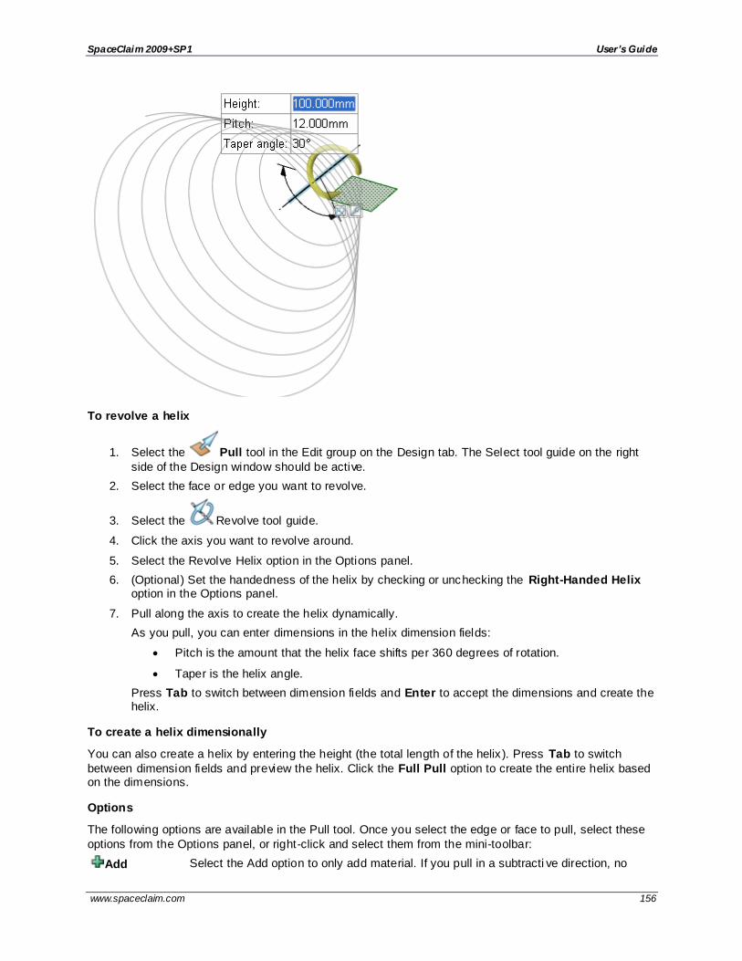
SpaceClaim 2009+SP1 User’s Guide
www.spaceclaim.com 156
To revolve a helix
1. Select the Pull tool in the Edit group on the Design tab. The Select tool guide on the right
side of the Design window should be active.
2. Select the face or edge you want to revolve.
3. Select the Revolve tool guide.
4. Click the axis you want to revolve around.
5. Select the Revolve Helix option in the Options panel.
6. (Optional) Set the handedness of the helix by checking or unchecking the Right-Handed Helix option in the Options panel.
7. Pull along the axis to create the helix dynamically.
As you pull, you can enter dimensions in the helix dimension fields:
Pitch is the amount that the helix face shifts per 360 degrees of rotation.
Taper is the helix angle.
Press Tab to switch between dimension fields and Enter to accept the dimensions and create the helix.
To create a helix dimensionally
You can also create a helix by entering the height (the total length of the helix ). Press Tab to switch
between dimension fields and preview the helix. Click the Full Pull option to create the entire helix based on the dimensions.
Options
The following options are available in the Pull tool. Once you select the edge or face to pull, select these
options from the Options panel, or right-click and select them from the mini-toolbar:
Add Select the Add option to only add material. If you pull in a subtracti ve direction, no

SpaceClaim 2009+SP1 User’s Guide
www.spaceclaim.com 157
change will occur. You can combine this option with other Pull options.
Cut Select the Cut option to only remove material. If you pull in an additive direction, no
change will occur. You can combine this option with other Pull options.
No Merge Pulls without merging into other objects even when the object pulled intersects with an existing object.
Pull Both Sides
Select a single, detached edge, imprinted edge, or surface, then click this option to pull both sides of the edge or surface at once.
Right-Handed Helix
Select this option to determine the direction in which the helix is revolved around its axis.
Sweeping
You can sweep a face, edge, surface, 3D curve, or other object along a trajectory with the Pull tool. Sweeping a face around a closed path creates a torus.
To sweep a face
1. Click Pull in the Edit group on the Design tab.
2. Select the profile you want to sweep.
3. Select the Sweep tool guide, then click the sweep trajectory. The sweep trajectory is shown in blue. Alt+double-click to select a tangent chain. Ctrl+click to add contiguous paths.
You can also select the profile to sweep and then Alt+click the sweep trajectory or Alt+Ctrl+click
multiple trajectories. The sweep tool is selected automatically.
If the trajectory along which you want to sweep is a non-linear curve, you can also Alt+click the curve, which selects the Sweep tool guide automatically.
If you select the Normal to Trajectory option, the sweep is aligned along the origin trajectory
To quickly sketch a face perpendicular to a desired trajectory, select the end of the trajectory and select a sketching tool to place the sketch grid at that point. Then draw the face.
4. (Optional) Select options from the Options panel, or right-click and select them from the mini-toolbar.
Select:
Select Normal to Trajectory to keep the swept surface normal to the sweep trajectory. If your sweep trajectory is perpendicular to the face you want to sweep, this option is enabled for you.
Select Scale Sections to control the effect of the vector from the 0-to-X trajectory so that it controls both orientation and scale of the sweep sections. Uncheck the box if you want the vector to control only the orientation of the sweep sections.
You can also select from the standard Pull options lis ted below.
5. Click and drag in the direction of the Pull arrow to sweep the selected objects, or select Full
Pull from the Options panel or mini-toolbar to sweep the entire length of the trajectory. If you select Full Pull and the profile being swept is in the middle of the trajectory, it will be swept in both directions.
You can also use the Up To tool guide to select a face or surface on which you want to end the sweep.

SpaceClaim 2009+SP1 User’s Guide
www.spaceclaim.com 158
Options
The following options are available in the Pull tool. Once you select the edge or face to pull, select these options from the Options panel, or right-click and select them from the mini-toolbar:
Add Select the Add option to only add material. If you pull in a subtractive direction, no
change will occur. You can combine this option with other Pull options.
Cut Select the Cut option to only remove material. If you pull in an additive direction, no change will occur. You can combine this option with other Pull options.
No Merge Pulls without merging into other objects even when the object pulled intersects with an existing object.
Pull Both
Sides
Select a single, detached edge, imprinted edge, or surface, then click this option to pull
both sides of the edge or surface at once.
Full Pull Once you select the edge about which to revolve or sweep, click this option to revolve
360 degrees or to the next face, sweep through the full trajectory, or blend through selected faces.
Up to Pulls the element so it mates with the surface of the selected body or be pulled up to a
plane through the selection. You can find this option in the mini-toolbar and it is the same as the Up To tool guide.
Examples
Hexagons swept around circular and hexagonal sweep paths
Sweeping along a primary trajectory with Normal to Trajectory selected. Every section plane that is normal to the origin trajectory is the exact same profile as the initial section, limited by the extents of the trajectory.

SpaceClaim 2009+SP1 User’s Guide
www.spaceclaim.com 159
Sweeping along a primary trajectory with Normal to Trajectory not selected. Every section plane that is parallel to the initial section profile is the exact same profile as that initial section, limited by the extents of
the trajectory.
Sweeping a rectangle along a trajectory with Normal to Trajectory selected.
Sweeping a rectangle along a trajectory with Normal to Trajectory
not selected.

SpaceClaim 2009+SP1 User’s Guide
www.spaceclaim.com 160
Sweeping a hole along a trajectory by selecting the axis of the hole, then the trajectory.
If you sweep a non-continuous profile, separate swept surfaces are created.
Sweeping with multiple trajectories
You can Alt+Ctrl+click to select multiple trajectories to sweep along. The trajectory you click first is the
origin trajectory (labeled O) and the second trajectory is labeled X. If you select the Normal to Trajectory option, the sweep is aligned along the origin trajectory. If the object being swept is in the middle of the sweep, you can pull in either direction to sweep only in that direction.
Sweeps can vary the sketch entities (or edges) along the sweep trajectory. The trajectories can be thought of as guides that make continual changes to the profiles as if they had been dragged while in Sketch mode. Tangency and other constraints are maintained.
When you sweep using more than two trajectories and Scale Sections is turned off, the profile lines and curves will follow the trajectories individually and constraints are preserved. You can see an example in the image below.
You can use a chain of tangent edges as a guide for Sweep.
The extent (or length) of a sweep is limited by the shortest trajectory . If the profile being swept intersects at any point along the trajectory, you can pull in either direction to sweep only in that direction. You can
also select Full Pull to create a bidirectional sweep that extends throughout the trajectory.
The sweep preview includes the following visual elements:
The blue square indicates the direction of the origin trajectory at its start, and is localized around the
origin trajectory’s intersection with the profile to be swept.
A right-angle symbol is displayed on the origin trajectory when you select the Normal to origin trajectory option.
The preview rectangles are green and scale with the sweep if you select the Scale sections option.
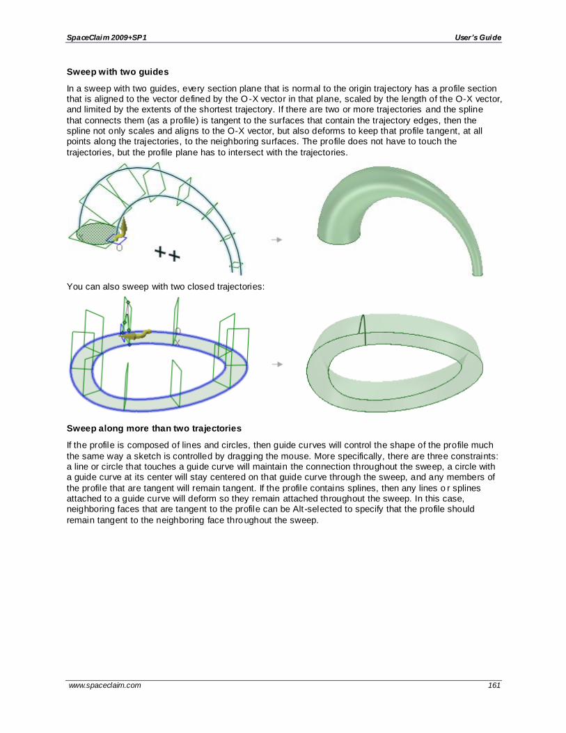
SpaceClaim 2009+SP1 User’s Guide
www.spaceclaim.com 161
Sweep with two guides
In a sweep with two guides, every section plane that is normal to the origin trajectory has a profile section that is aligned to the vector defined by the O-X vector in that plane, scaled by the length of the O-X vector, and limited by the extents of the shortest trajectory. If there are two or more trajectories and the spline
that connects them (as a profile) is tangent to the surfaces that contain the trajectory edges, then the spline not only scales and aligns to the O-X vector, but also deforms to keep that profile tangent, at all points along the trajectories, to the neighboring surfaces. The profile does not have to touch the
trajectories, but the profile plane has to intersect with the trajectories.
You can also sweep with two closed trajectories:
Sweep along more than two trajectories
If the profile is composed of lines and circles, then guide curves will control the shape of the profile much
the same way a sketch is controlled by dragging the mouse. More specifically, there are three constraints: a line or circle that touches a guide curve will maintain the connection throughout the sweep, a circle with a guide curve at its center will stay centered on that guide curve through the sweep, and any members of
the profile that are tangent will remain tangent. If the profile contains splines, then any lines o r splines attached to a guide curve will deform so they remain attached throughout the sweep. In this case, neighboring faces that are tangent to the profile can be Alt -selected to specify that the profile should
remain tangent to the neighboring face throughout the sweep.

SpaceClaim 2009+SP1 User’s Guide
www.spaceclaim.com 162
When sweeping, cross-sections can be displayed as a preview for their sweep along the trajectories, also shown in the figure above. You can control the display of the cross-sections with the Animate Full Pull
Advanced SpaceClaim option.
Sweep tangent to a surface
If you select a sweep trajectory that is the edge of a surface, and the object being swept is tangent to that surface, then the initial tangency is maintained along the entire sweep, as shown in the figure below.
Sweep with a trajectory and an axis
If you sweep a profile along a trajectory with an axis as the secondary trajectory, then the profile normal is maintained while the profile orientation changes as it is rotated around the axis.

SpaceClaim 2009+SP1 User’s Guide
www.spaceclaim.com 163
Sweeping with an axis
To set the orientation while sweeping
1. Click Pull in the Edit group on the Design tab.
2. Select the object you want to sweep.
3. Alt+click the primary trajectory.
4. Ctrl+Alt+click the secondary trajectory.
5. Click the Rotate tool guide and click the axis or line that will set the orientation during the sweep.
6. Drag to create the sweep.
The object being swept must be in the plane that contains the axis and an intersection with the baseline trajectory.
Examples
Setting the orientation of the selected object as it is swept along the trajectory

SpaceClaim 2009+SP1 User’s Guide
www.spaceclaim.com 164
Variable sweep with axis — Every section plane that is cut through a point on the origin trajectory and through the selected axis has a profile section that is aligned to the vector defined by the O -X vector in
that plane, scaled by the length of the O-X vector, and limited by the extents of the shortest trajectory. This makes every section appear to radiate around that selected Axis.
Drafting faces
You can draft faces around a plane or another face, edge, or surface with the Pull tool. Drafting changes the angle of the selected contiguous faces. For example, a mold designer drafts faces to facilitate removal of parts from the mold.
To draft a face
1. (Optional) Insert a plane around which you want to draft faces.
You need to do this when you want to draft around a plane that doesn't already exist as geometry in the design.
2. Click Pull in the Edit group on the Design tab. The Select tool guide on the right side of the
Design window should be active.
3. Select the face or contiguous faces you want to draft.
4. Alt+click the plane, face (including rounds), or surface about which you want to draft.

SpaceClaim 2009+SP1 User’s Guide
www.spaceclaim.com 165
You can also select the Draft tool guide , then click the face or surface. The draft plane, face,
or surface is shown in blue.
Tip: When you need to select more than one face or surface for the Alt -reference (or after selecting the Draft tool guide) then you have to hold the Ctrl and the Alt keys while selecting the
additional references.
If you select one edge loop, you can create an edge-driven draft. If you select two edge loops, you can create a split draft.
5. Click and drag in the direction of the Pull arrow to draft the selected faces.
To dimension the draft, type the rotation angle while you are pulling and press Enter.
Options
The following options are available in the Pull tool. Once you select the edge or face to pull, select these
options from the Options panel, or right-click and select them from the mini-toolbar:
Add Select the Add option to only add material. If you pull in a subtractive direction, no change will occur. You can combine this option with other Pull options.
Cut Select the Cut option to only remove material. If you pull in an additive direction, no change will occur. You can combine this option with other Pull options.
No Merge Pulls without merging into other objects even when the object pulled intersects with an
existing object.
Up to Pulls the element so it mates with the surface of the selected body or be pulled up to a plane through the selection. You can find this option in the mini-toolbar and it is the
same as the Up To tool guide.
Draft Both
Sides
Select this option to pivot the face on the opposite side of the reference face as well as the selected face.
Examples
Drafting faces around a plane. The drafted faces pivot around the face or plane you select as the draft
plane.
Drafting both sides around the plane.

SpaceClaim 2009+SP1 User’s Guide
www.spaceclaim.com 166
Drafting a face where a plane must be selected as the draft plane. See Inserting a plane for instructions to create a plane.
Drafting the offset faces (inside and the outside) of a shelled solid.
Drafting a set of surfaces about a planar surface not attached to the solid
Blending between faces
You can blend between two faces with the Pull tool. Once you have created a blend, you can use the
Tweak Face tool to edit the blended surfaces or faces.

SpaceClaim 2009+SP1 User’s Guide
www.spaceclaim.com 167
To blend between two faces
1. Click Pull in the Edit group on the Design tab. The Select tool guide on the right side of the
Design window should be active.
2. Select the surfaces or faces you want to blend through.
When you blend between two faces, the blend surface begins tangent to the edges of the initial
faces and ends tangent to the edges of the end faces. To prevent this behavior, select the edges you do not want to use for tangency. The figure above shows the blends created with and without the effects of the edges.
The edges of the blend are displayed. If they aren't, check that the Blend option is selected in
the Options window.
3. (Optional) Alt+click the edges or lines you want to use as guides for the blend.
4. (Optional) Click and drag the blend points to modify the blend edges.
5. Select from the following options in the Options panel:
Show take-off vectors to display guides which show the vectors between the faces. Drag a gray/purple ball to change the vector's direction. Drag a green ball to change the magnitude (how much influence the vector has) and the direction of the vector within the
plane that was set by the gray/purple handle.
Rotational blend to create cylinders and cones whenever possible during the creation of a blend. You must have selected faces rotated around a common axis.
Periodic blend to go all the way around when blending. You must have selected three or more faces rotated around a common axis, that also span an arc greater than 180 degrees. (Blending between 3 equal-radius circle faces creates a torus.)
Ruled sections to create straight edges when you pull between three or more surfaces or faces. When you blend between faces, this option has the same affect as selecting the face and its edges.
6. Click, drag, and release in the direction of the Pull arrow or select Full Pull from the Options panel or mini-toolbar to create the blend.
The blend is not created until you are finished dragging.

SpaceClaim 2009+SP1 User’s Guide
www.spaceclaim.com 168
Examples
Blend between two surfaces using splines to guide the blend
Blend with edge tangency (no edges pulled) and blend without edge tangency (edges pulled)

SpaceClaim 2009+SP1 User’s Guide
www.spaceclaim.com 169
Blend between multiple surfaces, automatically ordered to prevent self -intersection
Blend between multiple lines in space (profiles) with take -off vectors
Move the blend control handles for multiple circular faces, resulting in a blended solid

SpaceClaim 2009+SP1 User’s Guide
www.spaceclaim.com 170
Blending between two faces with holes
Blending between three faces with the Ruled sections option
Blending between edges
You can blend between two or more edges with the Pull tool in the Edit ribbon group on the Design tab.
When you pull between two edges with a face selected to control tangency, the tangent vector represents
the smallest angular deviation from the edge-to-edge line.
Swept blends
You can blend between two or more edges using one or more guide curves. If you select the Local guides option, then the edges will follow the guide curves. This is called a swept blend.
With regular (non-swept) blends, guide curves only affect the blending of segments of the profile to which they are attached. With swept blends, the whole profile is swept along the guide curve. All of the faces created by the blend are bent to follow the guide curve. Without the Local guides option selected, only the
faces touching the guide curve are affected by the guide.
In the example below, the first blend was done without the Local guides option. The second blend was done with the option.

SpaceClaim 2009+SP1 User’s Guide
www.spaceclaim.com 171
You will normally only use a single guide to create a swept blend; however, you can use multiple gu ide curves. When you have multiple guides, the guide curve closest to a given part of the profile most affects
the blending of that part of the profile.
Swept blends are different from sweep. A single sweep is always created from a single profile. With swept blends, two or more profiles are always required. Because a sweep only has a single profile, you have
limited control over the orientation and angle of the end cap of the sweep; it is always determined by sweeping the profile along the trajectory. When you create a swept blend, you can specify the end cap explicitly at whatever orientation (and shape) you desire.
When you select more than one trajectory, the additional trajectories give you more control over the final shape of the blend. Each trajectory affects the entities in the profile that are closest to the trajectory. Vertices that are between trajectories are controlled by curves that are blended between the neighboring
trajectories.
To blend between edges
1. Click Pull in the Edit group on the Design tab.
2. Click the Blend option in the Options window.
3. Click the starting edge of the blend.
4. Ctrl+click the ending edge of the blend.
5. Select from the following options in the Options panel:
Show take-off vectors to display guides which show the vectors between the faces. Drag a gray/purple ball to change the vector's direction. Drag a green ball to change the magnitude (how much influence the vector has) and the direction of the vector within the plane that was set by the gray/purple handle.
Rotational blend to create cylinders and cones whenever possible during the creation of a blend. You must have selected faces rotated around a common axis.
Ruled sections to create straight edges when you pull between three or more surfaces
or faces. When you blend between faces, this option has the same affect as selecting the face and its edges.
Local guides: Sweep the entire profile along the guide curve. You must select at least
two edges for a swept blend.
6. Click, drag, and release in the direction of the Pull arrow or select Full Pull from the Options
panel or mini-toolbar to create the blended surface.
When a blend between splines will self-intersect, the splines are modified slightly to prevent this from happening.

SpaceClaim 2009+SP1 User’s Guide
www.spaceclaim.com 172
To blend between multiple edges
1. Click Pull in the Edit group on the Design tab.
2. Hold Ctrl and select the two edges to blend between.
3. Hold Ctrl+Alt and select the edges that will guide the blend. A guide can contain multiple segments if the segments are tangent with each other. You can select as many guide curves as desired.
The edges of the blend are displayed. If they aren't, check that the Blend option is selected in
the Options window.
4. Select Full Pull from the Options panel or mini-toolbar to create the blended face.
If you create a blend that results in a surface contained within a solid, the surface remains a separate object.
Examples
Blending between a surface edge and line in space using the Full Pull option
Blending between two faces with multiple guides positioned along part of a periodic edge.
Blending between points
You can create a curve with the Pull tool by using the Blend option to blend between points. You can
blend between any two points to create a curve, or select multiple points to create a spline.
When you pull between two points with a face selected to control tangency, the tangent vector represents the smallest angular deviation from the point-to-point line.
To blend between points
1. Ctrl+click to select multiple points or vertices.
The Blend option is selected automatically.

SpaceClaim 2009+SP1 User’s Guide
www.spaceclaim.com 173
2. To make the pulled curve tangent:
Ctrl+click neighboring edges of the vertices if you want the blend curve to begin tangent
to one or more edges.
Alt+click one or more neighboring faces if you want the blend curve to be tangent to the face(s).
3. To make straight lines instead of curves, select the Ruled segments option in the Options panel.
The lines will be created in the Curves folder in the Structure tree.
4. Click the Full Pull option in the Options panel or mini-toolbar to create the curve.
5. If you want the curve to appear as a separate object in the Structure tree, right -click the curve and select Name Sketch Curve.
Examples
Blend curves tangent to neighboring edges
Blend curve tangent to a neighboring face
Blending between points with the Ruled segments option to force the creation of straight lines

SpaceClaim 2009+SP1 User’s Guide
www.spaceclaim.com 174
Creating slots
You can create slots from holes using the Pull tool. You can also edit slots. Slots maintain the relationship
between their faces.
If you pull a hole with a rounded or chamfered edge into a slot, the slot will have a rounded or chamfered edge.
To create a slot
1. Click Pull in the Edit group on the Design tab.
2. Select the axis of a hole.
If you have trouble selecting the axis, hover first over the inside face of the hole and the axis will appear.
3. (Optional) Hold Alt and click on a face, edge, or vertex to set the direction or trajectory of the Pull.
4. (Optional) Select the Pull Both Sides option to create the slot in both directions.
5. (Optional) Select Full Pull to pull the slot along the full length of the trajectory, if you selected one.
6. Pull the axis or face of a hole to create a slot.
To create a curved slot
1. Select the axis or face of a hole.
2. Select the Rotate tool guide and click the axis of the driving cylinder.
You can also Alt+click the axis of the driving cylinder.
3. Pull the hole to create a curved slot.
You can pull a curved slot 360 degrees to make a round cut.
To create a radial slot
1. Select the axis or face of a hole.
2. Do one of the following:
Alt-click the face of the driving cylinder to set the direction of the Pull towards the axis of the driving cylinder. Click the Pull Direction tool guide and pull the hole to create a radial
slot.
Ctrl-click the face of the driving cylinder to set the direction of the Pull towards the axis of the driving cylinder. Click the Pull Direction tool guide and pull the hole to offset the
cylinder and create a radial slot simultaneously.
Select the Pull arrow that points toward the axis and pull.
If you want to lengthen a radial slot while keeping it the same distance from a radial face, Ctrl+click the radial slot's axis and the face, then pull.
If you want to move a slot along with a radial face Ctrl+select the hole’s axis and the face, then Ctrl+pull.
Creating an offset of a radial slot
1. Select an axis of a slot.
2. Hold the Alt key and select the cylinder face or face to set the offset direction.
3. Hold the Ctrl key and pull or enter a radius value.

SpaceClaim 2009+SP1 User’s Guide
www.spaceclaim.com 175
To create a swept slot
1. Select the axis of a hole.
2. Select the Sweep tool guide , then click the sweep trajectory.
3. Click and drag in the direction of the Pull arrow to sweep the selected objects, or select Full
Pull from the Options panel or mini-toolbar to sweep the entire length of the trajectory. If you select Full Pull and the face or surface being swept is in the middle of the trajectory, it will be swept in both directions.
To edit a slot
You can modify a hole that was dragged to form a slot by pulling on any of the slot axes.
If the slot has a rounded or chamfered edge, double -click the round or chamfer to change its dimensions.
If you select Detach first in the Options panel, then the slot will become a solid i f you use the Move tool
to move it off the body, as shown below.
To move a slot radially
1. Select the Pull tool.
2. Select both axes of the slot.
3. Do one of the following:
Alt-click the face of the driving cylinder to set the direction of the Pull towards the axis of the driving cylinder. Click the Pull Direction tool guide and Ctrl-drag to move the slot radially.
Ctrl-click the face of the driving cylinder to set the direction of the Pull towards the axis of the driving cylinder. Click the Pull Direction tool guide and Ctrl-drag to offset the cylinder and move the slot.
Note: You can move a hole radially by pressing Shift while dragging it with the Pull tool.
To remove the slot relationship
Right -click a face of the slot and select Remove Association.
Any changes you make to the slot's face will affect only that face.
Examples

SpaceClaim 2009+SP1 User’s Guide
www.spaceclaim.com 176
Pulling a circular slot to make a round cut
Pulling mirrored holes to create slots
Creating a circular slot by entering an angle dimension with the Pull Both Sides option
Moving a hole radially

SpaceClaim 2009+SP1 User’s Guide
www.spaceclaim.com 177
Offsetting a radial slot
Creating a radial slot by selecting an axis or edge parallel to the hole’s axis as the Pull direction
Creating a slot using a vertex as the Pull direction
Scaling solids and surfaces
You can scale solids and surfaces with the Pull tool. You can scale multiple objects in different components.
To scale a solid or surface
1. Click Pull in the Edit group on the Design tab.
2. Select a solid or surface.

SpaceClaim 2009+SP1 User’s Guide
www.spaceclaim.com 178
3. Click the Scale Body tool guide.
4. Click a point, vertex, or origin to set the origin for scaling.
5. Pull to scale dynamically (a field appears to show the scale as you pull) or press the spacebar and enter the scale.
You can enter mathematical expressions to calculate a scale factor.
Select the solid or surface, Alt+click a vertex to anchor the scale, and pull.
To scale a solid asymmetrically
1. Click Pull in the Edit group on the Design tab.
2. Select a solid.
3. Click the Scale Body tool guide.
4. Hold Alt and select an origin axis, or hold Alt and Ctrl and select a point and a line.
5. Drag in either direction of the line to scale the part in that direction.
You can press the spacebar and enter a scale value while you are dragging.
To convert an existing solid or surface from millimeters to inches
1. Change the units to inches as described above.
2. Select the Pull tool in the Edit ribbon group on the Design tab.
3. Select the object you want to convert.
4. Scale the object by 25.4.
To scale a datum plane or axis
1. Click Pull in the Edit group on the Design tab.
2. Select the datum plane and/or axis and select a curve, surface, or solid.
You must hold Ctrl and select the plane. Box-select will not select it.
3. Click the Scale Body tool guide.
4. Select an anchor point.
5. Drag in the direction of the Pull arrow.
Examples
Scaling a solid asymmetrically

SpaceClaim 2009+SP1 User’s Guide
www.spaceclaim.com 179
Scaling a plane and an axis with a solid
Copying edges and faces
You can copy edges and faces by selecting the Pull tool 's Extrude Edge option. You can also copy edges and faces with the Move tool.
When copying and pasting the edge of a surface as a curve or line, the lines are placed on the active
layer and remain selected until you clear the selection. This feature is useful if you need references to rebuild a surface.
To copy an edge or edges
1. Click Pull in the Edit group on the Design tab.
2. Select the edge or edges you want to copy. Double-click to select a chain of edges.
3. Select the Copy Edge option in the Options panel or from the mini-toolbar.
You can also Ctrl+drag with the Pivot Edge or Extrude edge options selected to copy the edge.
The Pull arrow changes to show the two directions in which you can create copies of the edge. One arrow is highlighted to show the primary direction.
4. If the arrow pointing the direction in which you want to copy the edge is not highlighted, click the
arrow or press Tab to change the direction.
5. Drag the edge in the direction of the highlighted Pull arrow.
During the pull, the distance between the copied edge and the new edge is displayed. When you
create an external edge, a surface is created between the copied edge and the new one.
Press Ctrl and drag to copy the selected face.

SpaceClaim 2009+SP1 User’s Guide
www.spaceclaim.com 180
Examples
Copying edges to create new edges on a face
When copying an edge, the edge adjusts based on the solid's geometry
Copying a round face
Pulling with the Select tool
You can pull with the Select tool or the Pull tool.
To pull with the Select tool
Drag the vertex of a selected face to another vertex to pull the selected face, as shown in t he figures
below.

SpaceClaim 2009+SP1 User’s Guide
www.spaceclaim.com 181
Dragging a copy of a solid back into the solid
Pivoting with the Select tool
You can pivot an edge with the Select tool or the Pull tool.
To pivot an edge
Drag the vertex of a selected edge to another vertex to pivot the selected face, as shown in the figure below.
.

SpaceClaim 2009+SP1 User’s Guide
www.spaceclaim.com 182
Moving
Use the Move tool to move any object in 2D or 3D, including drawing sheet views. The behavior of the Move tool changes based on what you have selected.
You can select an entire object, such as a solid, a surface, or a sketch, and translate or rotate the
object.
Moving one side of a solid, surface, or sketch will enlarge or reduce the size of the object.
If you move an object into another object in the same component, the smaller object is merged into the larger one, and receives the larger object's properties.
Moving a component moves everything contained within the component.
Offset, mirror, and coaxial inferred relationships will affect Move.
When you move a component that has been assembled using assembly constraints, the Move handle is positioned at the constraint and the axes that are constrained are disabled. If the assembly
constraints only allow movement in one direction, then that direction will be automatically selected. For example, if you move a component with a Center Axes assembly constraint, the Move handle is positioned on the axis and you can only move the component in directions that will keep the axes
aligned.
To Move objects
1. Click Move in the Edit group on the Design tab.
2. Select the object(s) that you want to move.
3. Select the following options:
Move grid: Select this option to move the sketch grid.
Ruler: Can be used to dimension the move. See the instructions for dimensioning a move.
Maintain orientation: Keep the orientation of the object when rotating or moving along a
trajectory.
Create patterns: Create a pattern of the selected objects. Pattern relationships of sketch curves and points are lost when you go into Section or 3D mode.
Detach first: Detach the selected protrusions and depressions, move them, and reattach
them at the new location
Maintain sketch connectivity: Keeps the connections between a sketch curve and other curves that share its end points. If you deselect this option and move a sketch curve, the
curve will move independent of other curves.
4. Click an axis and drag in that direction to move the selected object.
A line extends from the Move handle axis to indicate the direction you selected for movement.
If the move fails, the Move handle is repositioned to the last valid location and orientation. If you are trying to move a protrusion surrounded by round faces, you may need to fill the rounds.
The cursor does not need to be on the axis to move the selected object. In fact, you may find it
easier to control the move if you drag some distance from the entity and the Move handle.
To move relative to other objects
Snap to a co-planar face: Hold Shift while dragging to snap to co-planar faces when you have the Move handle anchored to a planar face.

SpaceClaim 2009+SP1 User’s Guide
www.spaceclaim.com 183
Move an object up to another object: Click the Up To tool guide to move objects so the center of the Move handle is adjacent to the object.
Orient an object to another object: Select the object to move and a Move handle axis, then click the Orient to Object tool guide and select a second object. The selected object will be rotated so the selected Move handle axis is aligned with the second object.
To change the anchor location of the Move handle
Drag the yellow center sphere on the Move handle
Click the Anchor tool guide and select the face, edge, or vertex on which to place the Move handle.
The yellow center sphere turns into a blue cube when the Move handle is anchored.
To change the direction or trajectory for the move
Drag one of the small balls on the rotational axis to reorient the Move handle, or dimension the orientation by typing the rotation angle while you are dragging, then pressing Enter.
You can also Alt+click a point or line, or click the Move Direction tool guide, then click a point or line, to orient one of the Move handle's axes toward that point or along that line.
If you Alt+click a trajectory, you can move along the trajectory. Ctrl+Alt+click to add contiguous lines or edges to the trajectory.
If you Alt+click a plane, the direction of movement is set perpendicular to the plane.
To dimension a move
1. Follow the steps to move an object.
2. After you click an axis on the Move handle, click Ruler in the Options panel.
3. Click an edge or face to anchor the ruler.
The ruler is oriented along the selected Move handle axis.
4. Type a distance and press Enter.
To copy an object using the Move tool
Press Ctrl to copy the object selected for movement and place it at the location at which you drag or dimension the move.
You can press the spacebar to dimension the move.

SpaceClaim 2009+SP1 User’s Guide
www.spaceclaim.com 184
Double-click the Up To tool guide to make multiple copies of the selected object. To exit this mode, click on another tool or in empty space in the Design window.
Tool guides
Within the Move tool, there are several tool guides that let you specify the behavior of the Move tool:
The Select tool guide is active by default. When this tool guide is active, you can select faces, surfaces, solids, or components within the Move tool.
Click any object with the Select Component tool guide to select the solid to which the object belongs. If the solid is the only object in its component, the component will be selected.
Select a point, vertex, line, axis, plane, or planar face with the Move Direction tool guide to orient the Move handle and set the initial direction of the move. (The object will not move
until you drag.)
Select a set of lines or edges with the Move Along Trajectory tool guide to move the selected objects along that trajectory. For best results, perform Moves along trajectories in
small increments. If the object to be moved is a protrusion, it will be detached, then reattached in the new location. When you move a protrusion along a trajectory, rounds are automatically removed. Ctrl+Alt+click a face to control the orientation of the object being
moved or patterned along.
Select an object, then use the Anchor tool guide to select the face, edge, or vertex that will anchor the move. You can anchor the Move handle to a temporary object, such as the
intersection between two axes by Alt+Shift+clicking the two objects.
Select an object, then use the Fulcrum tool guide to move other objects around it. Select a pattern member to anchor it, or select a component to explode an assembly. See Moving
with the Fulcrum tool guide.
Once you select the object to move and a Move handle axis, use the Up To tool guide to select the object you want to move up to.
If a Move handle axis is selected, the Move is limited to that direction. If no handles are selected, the object is translated until the center of the Move handle lies on the selected reference. (A move handle must be selected to move up to the axis of an origin.)
In a linear move to an intersecting object, the center of the Move handle is moved to the selected object. If the two objects do not intersect, the first object is moved along the desired direction up to the closest point to the second object. You can use this tool guide to:
Select a point along a trajectory or the axis of an origin to move up to.
Move the sketch grid in Sketch and Section modes.
Move an axis so it is coincident with another axis in a body. If you move the axis of a pattern, all pattern members will move together to the new location.
You can double-click the Up To tool guide to keep it active. While the tool guide is active, it will copy faces and surfaces instead of moving them. To deactivate the tool guide, click it again, select another tool guide, or exit the Move tool.
Once you select the object to move and a Move handle axis, use the Orient to Object tool guide to click an object. The selected object will be rotated until the selected Move handle axis is aligned with the clicked object. You can also use this tool guide to rotate the sketch
grid in Sketch and Section modes.

SpaceClaim 2009+SP1 User’s Guide
www.spaceclaim.com 185
Options
The following options are available in the Move tool:
Move grid Select this option to move the sketch grid.
Ruler Once you select an axis on the Move handle, select this option and click an edge or face to anchor the ruler. The ruler is oriented along the selected Move handle axis. Enter a value to use the ruler to dimension the move.
Maintain orientation
Select this option to maintain the orientation of the object when rotating or moving along a trajectory.
Create patterns Select this option if you want to create a pattern by dragging selected objects with
the Move tool. Dragging creates a copy of the selected object, moves it to a new location, and creates a pattern relationship.
Detach first Select this option to detach selected protrusions and depressions, move them, and
reattach them at the new location.
Maintain sketch connectivity
Keep the connection between a sketch curve and other curves that share its end points. If you deselect this option and move a sketch curve, the curve will move
independent of other curves.
Keep beam fixed This option is for beams and causes the beam to remain fixed while the profile becomes offset from the beam. See Moving beams.
Examples
Moving a protrusion with rounds that intersects with a stepped solid with the Detach First option
Normal to Surface - While moving the diamond along the selected trajectory, Ctrl+Alt+click the face of the cylinder to set the orientation of the diamond normal to the cylinder.
Moving an imprinted face off of a solid face creates a surface.

SpaceClaim 2009+SP1 User’s Guide
www.spaceclaim.com 186
Moving imprinted edges on a face, and other intersecting imprinted edges are adjusted as needed. The examples above show how the edges are adjusted when the imprinted areas are moved.
Copying the red face multiple times by double-clicking the Up To tool guide to keep it active for more than one move.
Making copies by double-clicking the Up To tool guide works with sketches, too.
The Move handle
You will use the Move handle to move objects in 2D and 3D. The Move handle allows you to translate and rotate objects. You use the Move handle by clicking the axes of the Move handle and dragging to
move the selected object.
When you select the object you want to move, and click one of the Move tools, SpaceClaim guesses at the anchor point and orientation of the Move handle. If either of these is incorrect, you can change them.
You can adjust the size of the Move handle in Popular options.
To translate objects using the Move handle
1. Click the axis that is aligned with the direction you want to move the selected object.
2. Drag in the direction of the axis to move the object.
To rotate objects using the Move handle
Drag the curved rotational axis that is aligned with the direction you want to rotate the selected object.
or
Double-click the curved rotational axis to rotate the object 90°.

SpaceClaim 2009+SP1 User’s Guide
www.spaceclaim.com 187
To realign the axes of the Move handle
You can realign the Move handle in the following ways:
Drag the small balls on each rotation axis of the Move handle to reorient it. While dragging, you can also press the spacebar to enter the angle directly.
Drag the center ball of the Move handle (or use the Anchor tool guide) to place it on another solid, face, edge, or vertex. If you use this method, keep in mind that the selected object is still the one that is going to move.
Alt+click a point or line (or use the Move Direction tool guide) to orient the closest linear axis toward
that point or along the line.
Examples
Adjusting the size of the Move handle in Popular options
Creating patterns
You can create a pattern of protrusions or depressions (including slots), points, components, planes, origins, or axes. You can also create patterns of sketch curves. You cannot create a pattern of threads.
You can also create a pattern from a mix of object types, such as a pattern of holes (faces) and bolts (imported components). In SpaceClaim, any pattern member can be used to modify the pattern after you create it. If the change cannot be made to all pattern members, the member that cannot change is still
part of the pattern.
Any of the Move tool's tool guides are available to you while creating a pattern.
When you select a member of a pattern, you will see fields for the pattern count and distances rel ative to
the member you have selected, as shown above. Press Tab to move among the dimension and count fields.

SpaceClaim 2009+SP1 User’s Guide
www.spaceclaim.com 188
Icons next to the pattern’s dimensions and counts show which will be changed if you change the value of the highlighted field. The closed lock indicates that a dimension won’t change and the open
lock shows you it will change. You can override a lock on a dimension by clicking its icon to toggle it between locked and unlocked.
Dimension or count line placement, arrows, and value fields show you how the pattern will change if you change the value of a field.
Your selection determines how changes to the distance and count affect the pattern’s position. If you select one member of the pattern, the change is centered on that member. If you select all pattern members, the change is centered on the entire pattern, with the distance between members locked
by default. You can control which direction the pattern will grow based on which member you select and which count or distance you change.
Changing a pattern count in one direction does not change the distance between pattern members.
Instead, the overall distance of the pattern will change. This is indicated by the closed lock icon.
Circular patterns are anchored at the opposite end by default when you move one end.
Patterns of sketch entities and 3D curves are no longer patterns when they change into something else, such as a surface or solid. For example, if you pattern a C-shaped curve, then it will remain a
pattern when you switch from sketch mode to 3D mode. But if you close off the curve to make a box before you switch to 3D mode, then the boxes will become surfaces and will no longer be a pattern.
To create a linear pattern
1. Select a protrusion, depression, sketch, points, axes, planes, origins, or 3D curves to be the first
member of the pattern.
2. Click Move in the Edit section of the Design tab.
3. Select the Create patterns check box in the Options panel.
4. (Optional) Alt+click to set the direction for the pattern (or use the Direction tool guide).
5. Drag the first member to copy it to the location of the last member of the linear pattern. You can also select a direction arrow and press the spacebar to type a distance.
All pattern members will be created between the first member and this member in a straight line.
You can use the Up To tool guide to set the position.
6. The pattern count field is active when you release the mouse after dragging the pattern. Type a new value for the pattern count.
Press Tab to change the distance or spacing.
To create a pattern of a pattern
Follow the steps for the linear pattern, but select a linear pattern as the first member of the pattern.
To create the secondary pattern from the entire original pattern, right -click the pattern and click Select >
All Pattern Members. Only the pattern members that you select will be used to create the secondary pattern.
To create an arc, circular, or cylindrical pattern
1. Select a protrusion, depression, sketch, points, axes, planes, origins, or 3D curves to be the first
member of the pattern.
2. Click Move in the Edit section of the Design tab.
3. Select the Create patterns check box in the Options panel.
4. Click the Anchor tool guide and select an edge or axis where you want the center of the pattern.

SpaceClaim 2009+SP1 User’s Guide
www.spaceclaim.com 189
5. Drag a rotation handle on the Move tool.
As soon as you pass a certain rotation threshold, you can preview the possible patterns. If you
want a more closely-packed pattern, edit the pattern after you create it. If you want to create an arc pattern, release the mouse button at a location that does not form a circular pattern.
6. Release the mouse button to create the pattern.
7. Press Tab to enter the number of members you want to have in the whole pattern in the Count field.
To create a pattern that is greater than 180°, make a pattern that is less than 180° and drag one
end so the pattern is greater than 180° or edit the overall circular pattern's radial dimension.
To create a radial pattern
1. Select a protrusion, depression, sketch, points, axes, planes, origins, or 3D curves to be the first member of the pattern.
2. Click Move in the Edit section of the Design tab.
3. Select the Create patterns check box in the Options panel.
4. Use the Direction tool guide to set the direction of the Move tool toward the axis.
5. Drag the first member to copy it in a radial direction.
As soon as you pass a certain rotation threshold, you can preview the possible patterns. If you
want a more closely-packed pattern, edit the pattern after you create it. If you want to create an arc pattern, release the mouse button at a location that does not form a circular pattern.
6. Mouse up to select the radial pattern.
7. Press Tab to enter the number of members you want to have in the whole pattern in the Count field.
To create a radial circular pattern
1. Select all radial pattern members.
2. Click Move in the Edit section of the Design tab.
3. Re-anchor the Move tool on the circular axis.
4. Select the Create patterns check box in the Options panel.
5. Drag the radial pattern to form a circular pattern.
To create a pattern of points along an edge
1. Select a point to be the first member of the pattern.
2. Click Move in the Edit section of the Design tab.
3. Select the Create patterns check box in the Options panel.
4. Click the Move Along Trajectory tool guide.
5. Click one of the edges that connects to the vertex.
6. Click the Move handle axis.
7. Drag to create the end pattern member and create the pattern.
8. Press Tab to change the count, length, and percent fields to edit the pattern of points.
All points are associated with the edge, so that when the edge changes, the points also change as shown in the example below.

SpaceClaim 2009+SP1 User’s Guide
www.spaceclaim.com 190
To edit a pattern's properties
1. Select one pattern member to display the pattern count and dimensions.
2. Edit the pattern's properties.
Press Tab to switch between the fields.
Click the lock icon to lock or unlock a value.
3. Press Enter.
The result of editing the count and spacing is relative to the member of the pattern you select.
To quickly increase or decrease the number of pattern members, press Tab until the count field is highlighted, then hold the Alt key while you press the up or down arrow.
To move a pattern
1. Click Move in the Edit section of the Design tab.
2. Select a pattern member to move a linear pattern or the pattern axis to move a circular or arc pattern.
3. Move the pattern member with the Move handle.
If you move an interior member of a pattern and it is not anchored, all the pattern members move:
If you move a member at one end of a pattern, the member at the opposite end is anchored and
the pattern is skewed:
If you anchor a different member than the member opposite the direction you are moving, Move skews the pattern.
If you have a linear pattern in a radial direction and you move an interior member without setting an anchor, then the entire pattern shifts in the selected direction.
To move a radial pattern in a linear direction
1. Click Move in the Edit section of the Design tab.
2. Right -click a pattern member and click Select > All Pattern Members.
3. Select the Direction tool guide.
4. Click an object to set the direction of the move.
5. Drag the pattern.

SpaceClaim 2009+SP1 User’s Guide
www.spaceclaim.com 191
To adjust pattern distance or spacing
1. Click Select or Move in the Edit group on the Design tab.
2. Select a pattern member.
This member will serve as the anchor, and other pattern members will move relative to this member.
3. Press Tab until the field you want to change is highlighted:
Distance: This field is the overall distance of the pattern. The pattern member you select is anchored, and the length will change relative to this member. The arrows indicate the direction of change. You can see this field at the top of the image below.
Spacing: This field is the spacing between pattern members. This field has arrows in both directions and is located between two pattern members. The field is highlighted in blue in the image below.
Radial patterns: If you select a member of a radial pattern, you can change the angle between pattern members and the distance from the pattern members to the center of the pattern.
4. Type a new distance or angle and press Enter.
The spacing between all pattern members will change.
To remove a pattern member from the pattern
Right -click the face of the pattern member and select Unpattern Member. Doing this makes the member independent, so changes to the feature won't propagate to the pattern.
To create a pattern group
1. Select a pattern or pattern member in the Design window.
2. Click the Groups tab in the Structure panel.
3. Click Create Group.
A group is created that displays the number of members in the pattern. You can click on this group to select the pattern and change its parameters in the Design window.
To assemble components on a pattern
You can assemble a component with a pattern member, then propagate the component to all of the
pattern members. The component will be copied and assembled to each pattern member.
1. Assemble a component to some geometry that is a pattern member using the Align, Center, or Orient tools.
2. Right -click the component and select Update Components on Pattern.
The components will be propagated to the pattern, as shown below.

SpaceClaim 2009+SP1 User’s Guide
www.spaceclaim.com 192
Examples
Rectangular pattern
Arc pattern
Radial Pattern

SpaceClaim 2009+SP1 User’s Guide
www.spaceclaim.com 193
Radial circular pattern
A pattern of points automatically changes when the edge associated with it is lengthened or shortened.
Changing spacing between pattern members changes the pattern's overall length when the length field isn't locked.
A pattern of sketch objects is no longer a pattern when you switch to 3D mode and the sketched objects
are converted to surfaces.

SpaceClaim 2009+SP1 User’s Guide
www.spaceclaim.com 194
Sketch curve patterns can propagate in two dimensions. The pattern contains three elements in the X direction and two elements in the Y direction.
Exploding an assembly
1. Select all the components in the Structure tree that are part of the assembly you want to explode.
2. Anchor the Move handle on one component.
3. Select the Fulcrum tool guide and click another component.
4. Select an axis on the Move handle and drag to explode the assembly in that direction.
Pivoting and pulling solids
You can use the Move tool to pivot or pull a solid.
To pull a solid
1. Click the Move tool.
2. Select the face you want to move.
3. Use the Move handle to move the face.
The solid is extended in the direction of the move
To pivot a solid
1. Select an edge loop on the solid that you want to pivot.
2. Click a linear axis of the Move handle.
3. (Optional) Click the Fulcrum tool guide and click an alternate plane to pivot around.

SpaceClaim 2009+SP1 User’s Guide
www.spaceclaim.com 195
4. Drag to pivot the solid around a plane drawn through a point opposite the selected edge loop or to pivot the solid around the plane you selected with the Fulcrum tool guide.
If the Move tool cannot maintain a planar or cylindrical face while pivoting, it will create a blended face.
Moving with the Select tool
You can move solids and surfaces with the Select tool.
To move a solid or surface
You can do any of the following:
Select a vertex of a solid or surface, then drag it to move the solid or surface. (Surfaces on the same plane are treated as a single surface and move together.)
Alt+click a point, then drag the vertex to rotate in the plane of the screen.
Alt+click an edge or two points, then drag the vertex to rotate the object around the axis defined by
the line or points.
You can place the dragged vertex on a plane or edge by dragging until the plane or edge is highlighted.
Examples
The blue edge was selected using the Alt key, then the green vertex was dragged in the direction of the
arrow. The part pivots around the blue edge.

SpaceClaim 2009+SP1 User’s Guide
www.spaceclaim.com 196
The vertex highlighted in green was dragged down until the face shown on the right was highlighted. The triangular part moves down so the vertex is in the same plane as the face.
Moving with the Fulcrum tool guide
The Fulcrum tool guide moves objects around a point, edge, or face. You can use this tool guide to pivot patterns or faces, and to create a simple exploded assembly.
To move objects with the Fulcrum tool guide
1. Click Move in the Edit group on the Design tab.
2. Select the point(s ), edge(s), or face(s) you want to move. You can select surfaces, solids, or components in the Structure tree.
This object will be highlighted a shade darker than its normal color. Selected components will be
highlighted with a red bounding box.
3. Click the Fulcrum tool guide on the right side of the Design window.
4. Select the point, edge, or face you want to use as the fulcrum. You can select surfaces, solids, or
components in the Structure tree.
This object will be highlighted in blue.
5. Drag an arrow or radius on the Move handle to move the object(s).
Examples
In the examples below, the object was dragged in the direction indicated by the red arrow.
Moving an edge using another edge as the fulcrum point.

SpaceClaim 2009+SP1 User’s Guide
www.spaceclaim.com 197
Moving a pattern with one pattern member as the fulcrum point. You must select all the faces on the pattern member that you move.
Moving components with a face of one component as the fulcrum point. Select the components in the Structure tree.
Moving protrusions and depressions
You can move protrusions and depressions with the Select tool or the Move tool.
To move a protrusion or depression
1. Select a protrusion or depression.
2. Drag the protrusion or depression.
If two faces connect at an angle greater than 90 degrees, you can drag the protrusion across the two faces, as shown in the image below.
Driving modification with annotation dimensions
You can use 3D annotation dimensions to change your design using the Pull and Move tools. Annotation dimensions can be used in combination with ruler dimensions.
To view a video tutorial on this topic, see Tutorial: Annotation Dimensions on the SpaceClaim web site.

SpaceClaim 2009+SP1 User’s Guide
www.spaceclaim.com 198
To use 3D annotation dimensions with the Pull or Move tool
1. Click Pull or Move in the Edit group on the Design tab.
2. Select the objects you want to pull or move. You can select an edge, face, point, or surface.
3. If you are using the Move tool, select a direction on the Move handle.
4. Click the spark icon next to the dimension you want to use to drive the change. The icon turns
yellow when you hover over it with your mouse, as shown in the image above.
The dimension field can be edited when you click on the spark icon.
These icons appear when you use a tool that can be used with annotation dimensions to drive changes. The annotation dimension must be associated with the face, edge, or point you want to
change.
If you are using the Move tool and you don't see the spark icons, you need to select a direction on the Move handle or you must create a ruler dimension. You get more predictable results if you
re-anchor the Move handle to the appropriate face, edge, or point.
5. Type a new dimension and press Enter.
The objects you selected will change based on the dimension.
If the dimension you change isn't associated with the objects you selected, nothing will change and you will see an error message in the Status area on the lower right side of the SpaceClaim window.
If the tool can't make the change in the direction that the Pull or Move handle points toward, then it will try to make the change in the opposite direction to achieve the dimension you enter.
Examples
Selecting a dimension with the Pull tool active

SpaceClaim 2009+SP1 User’s Guide
www.spaceclaim.com 199
Selecting a dimension with the Move tool active. You must select a direction on the Move handle before you can select a dimension.
Changing the value of the dimension field
Using an angular dimension to Pull a face with a revolve axis set
Using a linear dimension to offset a face with Pull

SpaceClaim 2009+SP1 User’s Guide
www.spaceclaim.com 200
Using a linear dimension to change the angle of a face with Move
Note: We re-anchored the Move tool to the lower, horizontal edge of the face
Pulling with a radial dimension on a face that is offset with another cylindrical face; also works when you select both radial faces without an offset relation

SpaceClaim 2009+SP1 User’s Guide
www.spaceclaim.com 201
Filling
Use the Fill tool to fill in the selected region with the surrounding surface or solid. Fill can "heal" many cuts made into geometry, such as chamfers and rounds, subtractive revolves, protrusions, depressions, and regions removed by removing regions in the Combine tool. The Fill tool can also be used to simplify
surface edges and cap surfaces to form solids. You can select a combination of faces and edges to replace them with a single new face.
You can use the Fill tool in Sketch mode to fill a loop of sketch curves that is almos t closed, but that has
multiple small gaps. If the gaps are too large, multiple error messages appear to show you where the gaps are. You can also use it to concatenate multiple sketched curves.
You can also use the Fill tool when editing a layout. Fill functionality is useful when you sketch faces
across section lines, but do not want the section lines to split the surfaces when you switch to 3D.
Using the Fill tool
Click on one of the links below for detailed information about working with the Fill tool:
Sketch and layout curves
If you select one or more end points of sketch curves, the curves are concatenated into a single spline.
Neighboring sketch curves are merged into one selectable item with an underlying spline. The spline is not displayed until the concatenated curve is modified:
Let's look at the following sketch curves:
One of the rectangles isn't closed. If we fill this rectangle, the loop is automatically closed and it becomes
a surface:
The gap in this loop is small enough for the Fill tool to automatically close. Larger gaps will not be closed. If a gap is less than 1.5 times the length of the minor grid spacing on the sketch grid, the edges are

SpaceClaim 2009+SP1 User’s Guide
www.spaceclaim.com 202
extended to close the gap. If the gap is larger, a message appears in the status bar and the gap's endpoints flash.
The Fill tool also created surfaces from the other closed loops of sketch curves. The darker shaded areas in the image above show where the surface parts overlap. If we move the rectangle, we can see the surface that was created automatically:
The result only has edges for the sketch curves that we did not select, because the selected curves were used to create a separate surface.
Now let's go back and close the open rectangle, and let the Fill tool automatically create surfaces without
selecting any edges:
This surface has edges for every closed sketch curve. The same thing automatically happens if we go from sketch mode to 3D mode.
If we select all the sketch curves, then click Fill, we get a surface without any interior edges:
You can also fill layout and sketch loops:
And a loop of non-tangent 3D curves:

SpaceClaim 2009+SP1 User’s Guide
www.spaceclaim.com 203
Vertices
You can select any number of edge points in any order. Each edge point is removed and a spline is created to make a smooth curvature change between the neighboring edges to the point:
If you Fill a vertex on a solid, the system attempts to merge coincident edges into a single edge:
Edges on surfaces
If you select one surface edge in the shape of a spline or arc, the edge is simplified into a straight line:
If you select two or more edges of a surface, the edges are simplified with a straight edge between the
end points:
If you select an edge that is completely within a surface, the edge is removed:

SpaceClaim 2009+SP1 User’s Guide
www.spaceclaim.com 204
If you select all the edges that enclose a surface, the surface is simplified into a rectangle based on its extents:
If you select a single edge that lies on an analytic surface, Fill will simplify it with the neighboring edges:
You can fill irregular gaps on a circular surface, and the gap is simplified into a straight edge. Use Fill again on the straight edge, and the edge becomes round:
Edges on more than one face
If you select a chain of open, planar surface edges, Fill creates faces based on t he edges you select:
or

SpaceClaim 2009+SP1 User’s Guide
www.spaceclaim.com 205
If you select an open edge loop that belongs to multiple faces, Fill attempts to cap it with an analytic
surface (cylinder, cone, etc.):
If you select a series of planar edges, you will get aplanar face:
If you select a series of surface edges that are not planar, Fill extends neighboring faces if the Patch
Blend option is off:
If the Patch Blend option is turned on,

SpaceClaim 2009+SP1 User’s Guide
www.spaceclaim.com 206
If you select an edge loop and Alt+click to select neighboring faces, the new face will be tangent to any faces you used Alt+click to select:
You can also extend neighboring faces to fill sliver gaps (double click to get loop):
If you select open edges of a self-intersecting surface, Fill tries to form a solid and remove excess (also works in combine):
If you select an edge loop and use the Patch blend and Tangent extension options:

SpaceClaim 2009+SP1 User’s Guide
www.spaceclaim.com 207
When you fill a loop of edges, you can use Alt and select curves and the new face(s) will pass through the curves:
If you select an edge loop and guide curves, with or without the Tangent extension option (which applies to areas not influenced by guide curves):
If you select an imprinted edge on the face of a surface or solid, the imprinted edge is removed. This
works the same as delete:
If you select laminar edge(s) of a solid or surface, Fill simplifies the edges by replacing them with a single edge with the same geometry:

SpaceClaim 2009+SP1 User’s Guide
www.spaceclaim.com 208
Solids
If you select faces, Fill deletes them and extends neighboring faces:
If you select a chamfer or round, Fill removes them and adds them to a named group:
If you select rounds with neighboring rounds, Fill creates planar caps (because rounds should not be extended by definition):
If you select rounds on shelled parts, both faces of the shell are filled:
If you select joint edges created in Sheet Metal, the joints are removed:

SpaceClaim 2009+SP1 User’s Guide
www.spaceclaim.com 209
If you select two imprinted edges, as shown below, they are combined into one edge:
Faces and edges or sketch curves
With at least one face selected and at least one edge or sketch curve selected, Fill will remove the
selected faces and create a single new face using the removed faces and the selected edges as inputs:
If you select two faces or surfaces that don't touch, you can replace them with a single face. You must double-click to select the gap between the faces:
Any combination of sketch curves, layout curves, surface edges, and solid edges
When you select any combination of sketch curves, layout curves, surface edges, and solid edges that lie in the same plane and form a closed loop, Fill creates a planar surface:

SpaceClaim 2009+SP1 User’s Guide
www.spaceclaim.com 210
To fill a region
1. Select the edges that define a surface region, or the faces that define a region within or on a solid.
You can select an object in the Structure tree to simplify it.
You can select faces and the Fill tool will automatically create a p atch if you also select at least one edge.
2. Click the Fill tool or press F.
To fill sketch or layout lines
1. Select a closed or almost closed loop of sketch lines.
2. Click the Fill tool or press F.
If a gap is 1.5 times the length of the minor grid spacing on the sketch grid or less, the edges are
extended to close the gap. If the gap is larger, a message appears in the status bar and the gap's endpoints flash.
The mode is switched to 3D mode, and the filled loop becomes a surface.
You can select the face of a solid when only the edge is displayed (such as in a drawing sheet view) using the scroll wheel. The edge becomes a slightly thicker line when the face is highlighted. If you fill lines in a layout, you can then pull the surface into 3D from the layout, but remain in edit
layout mode after this action.
You can fill lines and edges whether or not the sketched lines you want to fill were sketched in the same plane as the edges. (If the lines are imprinted on a face and become edges, filling those
edges deletes them.)
Click the Fill tool in Sketch mode to fill any closed or almost closed loops and switch to 3D mode.
Tool guides
Within the Fill tool, there are several tool guides that let you specify the behavior of the Fill tool:
The Select tool guide is active by default. When this tool guide is active, you can select
edges and faces to be filled. You can click an edge loop or use box-select to select multiple objects.
The Select Guide Curves tool guide allows you to select a guide curve.
The Complete tool guide generates the filled face.

SpaceClaim 2009+SP1 User’s Guide
www.spaceclaim.com 211
Options
The following options are available for the Fill tool:
Patch blend Select this option to use the initial tangency of the neighboring faces to fill the selected edges with a patch blend. This option blends all the faces into a smooth, single -face
patch, instead of extending the faces that "own" the edge until they intersect. Alt+click the points that you want to blend through. This option is automatically selected when you hold the Alt key or use the Select Guide Curves tool guide to select a reference
curve.
The tangency of neighboring faces is ignored unless you hold Alt or click the Select Guide Curves tool guide and select them.
Show deviation
Shows a deviation analysis of the surface or face you created with the Patch blend option. The new face is temporarily colored to indicate the distance from points on its surface to the faces it was created from. Use the Color and Scale controls to change
how the analysis is displayed.
Examples
Simplifying edges
Simplifying edges across multiple faces
Filling with straight and curved edges

SpaceClaim 2009+SP1 User’s Guide
www.spaceclaim.com 212
Filling with curved edges as guides
Capping a surface
Capping a surface that crosses multiple edges
Selecting internal edges to keep them after filling.
Selecting lines to simplify a surface by filling. Internal edges
are removed.
Filling edges to form a solid

SpaceClaim 2009+SP1 User’s Guide
www.spaceclaim.com 213
Patch blend with and without tangent extension. The Tangent extension option is select on the left, and not selected on the right.
Removing rounds
You can use the Fill tool to remove and cap round faces. You might want to do this if you are trying to move a protrusion surrounded by round faces and it cannot be moved because the rounds create
impossible geometry.
To fill a round or chamfer
1. Select the round or chamfer.
2. Click the Fill tool or press F to fill the round and create caps if necessary.
A RoundGroup is created in the Groups panel each time you fill a round.
(You can fill any round created in SpaceClaim, even a round that removes the underlying face, until the round is changed by some other action.)
To remove a round face
1. Select the round face.
2. Click the Fill tool or press F.
If removing a face makes an invalid solid, the solid is converted to a surface.
If a round face is difficult to remove, try Alt+clicking it with the Fill tool, or using the Replace tool.
Capping multiple round faces
When multiple selected round faces are removed by the Fill tool, they are removed in a specific order so that they can be restored by right-clicking and selecting Reattach Rounds for each group, in reverse
order.
Usually you can just select all the round faces and click the Fill tool to remove and cap them all. However, sometimes this is not possible. In that case, select one round and fill it . If that works, undo and select that
round and the next. Undo. Continue adding rounds to your selection and trying to fill them until the fill fails. Now you have identified one of the rounds that is causing the problem. Next, fill all the rounds that fil led successfully. Finally, repeat this process in the other direction of the round tangent chain. Once you have
filled all the rounds except for the one or two causing the problem, select the one causing the problem

SpaceClaim 2009+SP1 User’s Guide
www.spaceclaim.com 214
and its two neighbors. Then click Fill. This process allows more options for the extension of neighboring edges to intersect and cap the round.
If you are experiencing difficulty filling a chain of round faces, first split the round faces, then fill the newly created faces. Then fill the remaining round faces.
Examples
A difficult -to-remove round replaced before removing
Filling a corner round that was created as a surface-surface round in an imported design

SpaceClaim 2009+SP1 User’s Guide
www.spaceclaim.com 215
About to fill imported geometry bounded by surface rounds
Filling a rounded edge chain - the original chain to be filled, chain after splitting round faces, and filled chain
If a round cannot be removed, a "stop face" is added and round removal is discontinued (A stop face is a cap or vent face.)

SpaceClaim 2009+SP1 User’s Guide
www.spaceclaim.com 216
You can fill a chain of round faces when only one end of the round chain has a stop face.

SpaceClaim 2009+SP1 User’s Guide
www.spaceclaim.com 217
Tweaking a face You can edit any face or surface with Tweak Face to change its surface geometry. This tool is available in
3D mode and in drawings.
The degree (or complexity) of a primitive face is automatically increased when you edit it with the Tweak Faces tool. make the editing process smooth and seamless, so curves are smooth when you add them.
Surfaces are checked for self-intersection when you modify the surface using its control points. You will receive an error message if a change would create a self-intersecting surface.
If you save a selection in the Selection panel and it includes control points, the Face Edit tab will
automatically open when you load that selection.
To tweak a face
1. Click Tweak Face in the Edit group on the Design tab.
The Face Edit tab appears in the ribbon bar.
2. Select an editing method:
Control Points to expose the control points for the face or surface so you can move them.
Control Curves to expose the control curves for the face or surface so you can move them.
Blend Curves to edit faces or surfaces that can be recreated as a blend.
Sweep Curves to edit faces or surfaces created with sweep.
3. Select a control point or curve on the face.
Hold Ctrl or draw a box to select multiple points or curves.
4. (Optional) Use the controls in the Select group to expand or contract your selection:
The U direction is indicated by blue lines in the Design window, and the V direction is indicated by red lines.
Click or to expand the selection so it includes all points in the U (blue) or V (red)
direction.
Click or to expand the selection so it includes the next point in the U (blue) or V
(red) direction.
Click or to reduce the selection by one point in the U (blue) or V (red) direction.
5. Select a tool to edit the face or surface:
Add Control Curve
Move
Scale
Or any other tool on the Design tab.

SpaceClaim 2009+SP1 User’s Guide
www.spaceclaim.com 218
6. (Optional) Show a grid, curvature, or comb on the face or surface.
7. (Optional) Select Show Off-Face Control Points to display all control points. If this option is not
selected, you won't see control points that don't affect the surface.
8. (Optional) Select Show Periodic Seams when you are editing periodic faces (cylinders, cones, and other revolved surfaces) if you need to see the beginning seam of the surface. This may help
you see of the characteristics or behavior of some periodic faces as you edit.
9. Click Close Surface Tools to close the tab and end your editing session.
Tweak face editing methods
You can think of the editing methods as modes. Different controls are displayed for each method, and these controls allow you to adjust the face or surface differently.
You can choose from the following methods:
Control points
Use this method when you want to change a face by moving its control points.
Control curves
Use this method when you want to change a face by changing its control curves.
Blend curves
Use this method when you want to change a face by changing its blend curves.

SpaceClaim 2009+SP1 User’s Guide
www.spaceclaim.com 219
Sweep curves
Use this method when you are editing a face or surface
created by sweeping and you want to change a face by changing its sweep curves.
Add a control curve
You can add control curves to a face or surface when any editing method is active.
To add a control curve
1. Click Add Control Curve in the Edit group on the Face Edit tab.
The Tweak Face tool must be active for this tab to be visible.
2. Click the point on the face or surface where you want to add the control curve.
You can use temporary geometry to help you find the point where you want to add a control curve.
Show grid, curvature, or comb
These display modes can help you see the contours of a face or surface.
Grid displays a grid on your face or surface. This is similar to the Grid tool on the Measure tab.
Curvature displays a gradient on your face or surface. The curvature with the smallest radius is shown in the maximum color. The curvature with the smallest radius, or no radius, is shown in the minimum color. This is similar to the Curvature tool on the Measure tab.
To show a grid on your face or surface
1. Select Grid in the Show section on the Face Edit tab.
2. (Optional) Change the Color and Scale of the grid.
To show curvature on your face or surface
1. Select Curvature in the Show section on the Face Edit tab.
2. (Optional) Change the shading colors under Curvature in the ribbon group.
The maximum color is on the left and the minimum color is on the right.
To show a fringe graph on your face or surface
1. Select Porcupine in the Show section on the Face Edit tab.
2. (Optional) Adjust the Density to change the number of fringes displayed along the curve.
3. (Optional) Adjust the Scale to change the length of the fringes relative to the amount of curvature.

SpaceClaim 2009+SP1 User’s Guide
www.spaceclaim.com 220
Replacing faces Use the Replace tool to replace one face (or multiple faces) with another face (or faces) or to simplify a
design.
If you want to replace several faces to simplify a design, see Simplify a design.
To replace a face
1. Click Replace in the Edit group on the Design tab.
2. Select the target, which is the face you want to replace.
Hold the Ctrl key or box-select to select more than one face.
3. Select the source, which is the face you want to replace with.
Click the Source tool guide to make it sticky and select more than one face to replace with.
You can select objects in the Structure tree, including planes.
4. (Optional) To add faces that you want to replace, click the Target tool guide or hold Ctrl and select additional faces.
5. To clear your selection and start over, click in empty space in the Design window.
6. Click the Complete tool guide to replace the faces.
Preselect faces for the Replace tool by clicking on the target and then hold Alt and click on the
source. Click Replace and the faces will be replaced.
To simplify or align faces
1. Click Replace in the Edit group on the Design tab.
2. Hold Ctrl and click each face that you want to simplify.
The faces are displayed with a pulsating red glow to indicate that they can be simplified or aligned.
3. Click the Complete tool guide or press the Enter key.
To simplify curves
1. Click Replace in the Edit group on the Design tab.
2. Hold Ctrl and click each curve (non-planar line) that you want to simplify.
The lines are displayed with a pulsating red glow to indicate that they can be simplified or aligned.
3. Click the Complete tool guide or press the Enter key.
Tool guides
Within the Replace tool, there are several tool guides that help step you through the editing process:

SpaceClaim 2009+SP1 User’s Guide
www.spaceclaim.com 221
If you did not pre-select the face that you want to replace, you can select it from within the Replace tool using the Target tool guide.
Click the face you want to replace the target face with using the Source tool guide.
Click the Complete tool guide to replace the target face with the source face, or to simplify or align the target face.
Examples
Faces that are almost planar targeted for alignment
Replacing several faces in a depression by several other faces.
You can also replace multiple faces of a protrusion by multiple faces of a selected surface.
Three faces highlighted in red because they can be simplified

SpaceClaim 2009+SP1 User’s Guide
www.spaceclaim.com 222
Intersecting You can use the intersect tools to merge and split a solid or surface in your design with another solid or
surface. You can merge and split solids or surfaces with other solids or surfaces, split a solid with a face, and split a face with another face. You can also project the edges of a face onto other solids and surfaces in your design.
SpaceClaim's intersection capabilities include the full suite of geometry combination, all done with one major tool (Combine) and two minor ones (Split Solid and Split Face). Combine always takes two or more objects. The split tools always act on one object and that object is automatically selected from the cutter
or projection face.
To understand what the Combine tool can do, the first step is to know which objects can be handled. Solid objects have faces that meet at corner edges. Edges that lie on faces can be deleted, but corners
cannot. Surface objects have faces that come together at internal edges, and are surrounded by outside edges. Outside edges can be extended. Internal edges can be deleted if they are bounded by planar faces. For the purposes of combine, planes can be thought of as surface faces that extend across the
design.
When surfaces enclose a volume, they automatically change into solid objects. When edges of the same surface become coincident, they will automatically merge. Planes cannot be split by any combine
operation, but they can be used to split with. In general, layer, color, and visibility in the structure tree propagates from the first selected item (the target) to the result. What happens as a result of the combination can be overridden with the options (both in the panel and the mini -toolbar). When you use
the Combine or Split tools, the newly created objects have the layer properties of the previous objects.
You have complete control over the pieces that solids and surfaces get cut into. When appropriate, SpaceClaim prompts you to remove regions, but you can choose to keep or remove those regions.
When using the intersect tools, the original, individual layers and colors of the objects are maintained.
Intersect ribbon group
The Intersect ribbon group contains the following tools:
Use the Combine tool to merge and split solids and surfaces.
Use the Split Solid tool to split a solid by one or more of its faces or edges. Then select one or
more regions for deletion.
Use the Split Face tool to create an edge on a face by splitting it with another face or surface.
Use the Project to Solid tool to create edges on a solid's face by extending the edges of another solid or surface.

SpaceClaim 2009+SP1 User’s Guide
www.spaceclaim.com 223
Combining and splitting Use the Combine tool to merge and split solids and surfaces. These actions are sometimes known as
Boolean operations.
The Combine tool works in two modes:
Explicit mode is activated by clicking a Combine tool guide. In this mode, once a tool guide is clicked,
it remains selected until another tool guide is clicked. This mode works just like any other tool. You can box-select multiple targets and cut them without automatically merging them.
For example, if you click the Select Target tool guide, you can click an object to add it to the selection
and click a selected object to remove it from the selection. You can also use box -select. (Nothing is merged.)
If you click the Merge tool guide, the selected targets are merged. You can click more objects to
merge them to the targets or use box-select.
If you click the Cutter tool guide, every object you click becomes a cutter and cuts the target immediately. You can also use box -select to create cutters.
To delete regions created by the cuts, you must click the Delete Regions tool guide then click the region you want to delete.
Implicit mode automatically activates tool guides and moves you through the work flow. This
predictive mode exhibits the same behavior as the Combine tool had in previous SpaceClaim releases, although you can now box-select multiple cutters to add even more efficiency.
In both modes, if you select objects, then click the Combine tool, the objects are automatically
merged. The procedures in this section describe Fast mode behavior.
When you use a pattern with the Combine tool, the entire pattern is merged or used to cut the target.
You can use a locked body as a cutter with the Combine tool, but you cannot use it as target. See
Locking and unlocking objects.
To merge solids and surfaces
1. Click Combine.
2. Select the target solid or surface.
3. Ctrl+click additional solids or surfaces to merge them.
Detailed instructions
1. Click Combine in the Intersect group on the Design tab.
2. Click the first solid or surface.
You can select objects for Combine in the structure tree. If you select a component, all objects
belonging to that component will be selected.
3. Ctrl+click additional solids or surfaces to merge them.
The Structure tree shows the merge.
The tool is reset if you click in an empty spot in the design area.
Solids can be merged with solids, and surfaces with surfaces. Solids and surfaces can only be merged if
the surfaces make a region that can be added to or cut out of the solid.
When you combine and merge, the Cutter object is the second selection and will be added to the first object. It is not used as a cutter but the name of the tool guide doesn't change.

SpaceClaim 2009+SP1 User’s Guide
www.spaceclaim.com 224
For example, if you select the face of a cylinder, copy and paste it, then you can merge it with the soli d used to create it.
Ctrl+click the solids or surfaces you want to combine in the Structure tree, then click the Combine tool to merge them.
You can box select multiple solids or surfaces to merge them in one operation.
To split solids and surfaces
1. Click Combine.
2. Select the target.
3. Select one or more object to use as the cutter.
4. (Optional) Select the region of the target to delete.
Detailed instructions
1. Click Combine in the Intersect group on the Design tab.
2. Select the solid or surface you want to cut.
The Select Cutter tool guide is activated.
You can select objects for Combine in the structure tree. If you select a component, all objects belonging to that component will be selected.
You can use temporary geometry to split an object.
3. (Optional) Control the behavior of the cut by selecting options.
4. Click one or more surface you want to use to cut the solid.
Depending on the option you chose, the cutting surface will be kept or deleted. Review the information in the Structure panel to see the solids or surfaces created by the cut.
Mouse over the target solid to see the regions created by the cut.
5. Click each region you want to delete.
When you are finished selecting the areas to be deleted, click the Select Target tool guide to combine some more, or select another tool.
The tool is reset if you click in an empty spot in the design area.
If you want to split a body by a face of the body, select the Split Solid tool.
If you want to create an edge on a face, select the Split Face tool.
Tool guides
Within the Combine tool, there are several tool guides that help step you through the splitting process.
The Select Target tool guide is active by default. If you did not pre-select the target solid or surface, you can select it from within the Combine tool using the Select tool guide.
Click the Select Bodies to Merge tool guide to select multiple solids or surfaces to merge together. Tool guides that appear with a double outline are "sticky," and allow you to perform
the same action repeatedly, without holding the Ctrl key. For example, when this tool guide appears with a double outline, just keep clicking objects to merge each object with the previous one. To "unstick" the tool guide, you can click it again, click another tool guide, or
click an empty place in the Design window.

SpaceClaim 2009+SP1 User’s Guide
www.spaceclaim.com 225
The Select Cutter tool guide activates once you select a target. When this tool guide is active, click to select the solid or surface you want to use to cut the target. You can Ctrl+click
when this tool guide is active if you need to add other bodies to your cutter selection.
The Select Regions tool guide activates once the target is cut. When this tool guide is active, mouse over the target to preview the regions created by the cut. Click a red region to
delete it.
Options
The following options are available for the Combine tool. Select one or more of these options from the Options docking panel, or right-click and select them from the mini-toolbar:
Merge when done
Select this option to merge all touching solids or surfaces when you exit the Combine tool. Hidden objects are not merged. This saves you the extra step of selecting all the cut-up regions after you are done with a complicated slice-and-dice session, and
manually merging them all back together.
Imprint
curves
Select this option to create edges at intersections instead of selecting regions. You will not be able to preview regions for deletion. As soon as a region is selected for deletion,
this option is disabled.
Keep
cutter
SpaceClaim assumes that you created a cutter object to be used only for cutting. If you want to keep the cutting surface in your design, select this option. If this option is not
selected, then the cutting surface is automatically deleted as soon as you select it. In other words, cutter objects are normally "used up" unless you select this option. A kept cutter can be a surface or solid, but either way only the regions of the target can be
removed.
If you are splitting surfaces, check this option to prevent the cutter object from being split by the target object.
This option is automatically selected if the cutter object is locked.
Make all
regions
Select this option to cut the target object with the cutter object and the cutter object with the target object. Target and cutter must be the same type of object, either both solids or
both surfaces. Because this option can create a large number of regions, it can be helpful to use this option along with the Merge When Done option to quickly merge all remaining regions when you click another tool or press Enter to finish using Combine.
Merging solids and surfaces
Use the Combine tool to merge solids and surfaces.
To merge solids and surfaces
1. Select the Combine tool from the Intersect ribbon group or press I.
2. Click the first solid or surface.
3. Ctrl+click additional solids or surfaces to merge them.
The Structure tree shows the merge.
Ctrl+click the solids or surfaces you want to combine in the Structure tree, then click the Combine
tool to merge them.
Solids can be merged with solids, and surfaces with surfaces. Solids and surfaces can only be merged if the surfaces make a region that can be added to or cut out of the solid. For example, if you select the
face of a cylinder, copy and paste it, then you can merge it with the solid used to create it.

SpaceClaim 2009+SP1 User’s Guide
www.spaceclaim.com 226
Merging solids
You can merge two or more solids with the Combine tool.
To merge two solids
1. Select the Combine tool from the Intersect ribbon group.
2. Click the first solid.
3. Ctrl+click the second solid to merge it with the first solid.
The second solid takes on the color and visibility properties of the first solid. The Structure tree
shows the merge.
To merge multiple solids
1. Select the solids you want to combine using box selection.
2. Select the Combine tool from the Intersect ribbon group.
The solids take on the color and visibility properties of the merged solid that appeared top -most in the Structure tree. The Structure tree shows the merge.
You can also select the Combine tool, select the first solid, then Ctrl+click each individual solid you want to merge.
Merging surface protrusions
You can merge a surface that forms a protrusion to a solid.
To merge a surface protrusion
1. Select the Combine tool from the Intersect ribbon group.
2. Click the first solid.
3. Ctrl+click a surface that could create a protrusion on the solid to merge it with the solid.
The surface becomes a protrusion on the solid and takes on the color and visibility properties of
the first solid. The Structure tree shows the merge.
Merging surfaces
You can merge surfaces with the Combine tool. Surface must share edges to be merged. If surfaces enclose a volume, you can use the Combine tool to quickly convert the enclosed volume into a solid and
trim the extra.
Sometimes, if you manipulate a surface so that it becomes self-intersecting, you may need to create a solid from the surface that remains.
To merge surfaces that share edges
1. Select the Combine tool from the Intersect ribbon group.
2. Click the first surface.
3. Ctrl+click the second surface to merge it with the first surface.
The second surface takes on the color and visibility properties of the first surface. The Structure tree shows the merge.

SpaceClaim 2009+SP1 User’s Guide
www.spaceclaim.com 227
To merge surfaces that enclose a volume
1. Select the surfaces that intersect to form an enclosed region using box selection.
2. Select the Combine tool from the Intersect ribbon group.
The enclosed region becomes a solid and takes on the color and visibility properties of the merged surface that appeared top-most in the Structure tree. The Structure tree shows the merge.
To create a solid from a self-intersecting single surface
1. Click the Select tool in the Edit ribbon group.
2. Select the "open" edge of the set of surfaces, shown in black.
3. Click the Combine tool.
To repair a self-intersecting surface
1. Click the Select tool in the Edit ribbon group.
2. Double-click the edge loops.
3. Click the Combine tool.
Example
Six surfaces enclosing a volume, box-selected and combined with the Combine tool
Repairing a self-intersecting surface with the Combine tool

SpaceClaim 2009+SP1 User’s Guide
www.spaceclaim.com 228
Ctrl+click to select an open edge loop of a surface, then close the surfaces with the Combine tool
Capping a surface with a plane
Ctrl+click a surface and a plane to cap the surface.
Splitting solids and surfaces
Use the Combine tool to split solids and surfaces.
To split solids and surfaces
1. Click the Combine tool from the Intersect ribbon group or press I.
2. Select the solid or surface you want to cut.
The Select Cutter tool guide is activated.
3. (Optional) Control the behavior of the cut by selecting options.
4. Click the surface you want to use to cut the solid.
Depending on the option you chose, the cutting surface will be kept or deleted. Review the information in the Structure panel to see the solids or surfaces created by the cut.
Mouse over the target solid to see the regions created by the cut.
5. Click each region you want to delete.
When you are finished selecting the areas to be deleted, click the Select Target tool guide to
combine some more, or select another tool.
If you want to split a body by a face of the body, select the Split Solid tool.
If you want to create an edge on a face, select the Split Face tool.

SpaceClaim 2009+SP1 User’s Guide
www.spaceclaim.com 229
To split the target object with the cutter object and the cutter object with the target object
1. Select the Combine tool from the Intersect ribbon group.
2. Select the Make all regions option.
3. Click the objects you want to cut.
Target and cutter must be the same type of object, either both solids or both surfaces.
4. Mouse over the surface to see the regions created by the cut.
Because this option can create a large number of regions, we recommend using this option along
with the Merge When Done option to quickly merge all remaining regions when you click another tool or press Esc to finish using Combine.
5. Click the region you want to delete.

SpaceClaim 2009+SP1 User’s Guide
www.spaceclaim.com 230
Examples
Using two surfaces as the cutter, when the surfaces can't be merged outside of the region where they intersect the target. The two surfaces are merged to create a cut in the target.
Splitting a solid with a surface, plane, or another solid
Use the Combine tool to split solids. Solids can be split by surfaces, planes, and other solids.
Split a solid with a solid
1. Select the Combine tool from the Intersect ribbon group.
2. Click the solid you want to cut.
3. Click the solid you want to cut with.
4. Mouse over the solid to see the regions created by the cut.
5. Click the region you want to delete.
The regions you can delete are highlighted in red.
Split a solid with a surface or a plane
1. Select the Combine tool from the Intersect ribbon group.
2. Click the solid you want to cut.
3. Click the surface you want to cut the solid with.
You can Ctrl+click multiple surfaces that together completely intersect a solid.
4. Mouse over the solid to see the regions created by the cut.
5. Click the region you want to delete.
The regions you can delete are highlighted in red.
Using the Split Solid tool
Use the Split Solid tool to split a solid by one or more of its faces or edges. Then select one or more regions for deletion. The Split Solid tool expects that you have already selected the cutter objects. From these faces or edges, the single target body is inferred, since a face or edge can only belong to one solid

SpaceClaim 2009+SP1 User’s Guide
www.spaceclaim.com 231
or surface. If only one solid face is selected as a cutter, the default action is to extend that face to cut as far as it can through the solid. If a face of a surface is selected, then it is automatically removed.
The Split Solid tool works in two modes:
"Slow mode" is activated by clicking a Split Solid tool guide. In this mode, once a tool guide is clicked, it remains selected until another tool guide is clicked. This mode works just like any other tool.
"Fast mode" automatically activates tool guides and moves you through the work flow. This predictive mode allows you to box-select multiple cutters to add even more efficiency.
You can use the Split Solid tool to:
Split a solid by its edges
Split a solid by its faces
You can select a solid or surface from the Structure tree as the target and a plane from the Structure tree as the cutter.
To split a solid by one of its faces
1. Click the Split Solid tool from the Intersect ribbon group.
2. Select the faces or edges you want to use to cut the body.
Hold Ctrl and click or draw a box to select multiple faces or edges.
You can create temporary geometry and select it to cut the body.
3. Mouse over the solid to see the regions created by the cut.
4. (Optional) Click a region to delete it.
When you are finished deleting regions, select another tool.
If the selected edges do not completely encircle a portion of a solid or surface, no region selection
can occur.
Select a face with the Select tool, then select the Split Solid tool to cut the solid with the face.
Tool guides
Within the Split Solid tool, there are several tool guides that help step you through the splitting process:
The Select Cutter tool guide is active by default. When this tool guide is active, click to
select the face you want to use to cut the solid.
The Select Regions tool guide activates once you once the solid is cut by the face. When
this tool guide is active, mouse over the target to see the regions created by the cut. The regions you can delete are highlighted in red.
Options
The following options are available in the Split Solid tool. Once you select the edge or face to pull, select
these options from the Options docking panel, or right-click and select them from the mini-toolbar:
Merge when done
Select this option to merge all touching solids or surfaces when you exit the Split Solid tool. Hidden objects are not merged.
Extend faces Extends the selected cutter face to cut through the target solid.

SpaceClaim 2009+SP1 User’s Guide
www.spaceclaim.com 232
Examples
Solid split by a spline face
Splitting a face
Use the Split Face tool to create an edge on a face or surface by splitting it with another face or edge.
To create an edge on a face
1. Click Split Face in the Intersect group on the Design tab.
2. (Optional) Select a tool guide.
Mouse over faces or edges in your design to preview the edge that will be created on the target. Dimensions are displayed along the U and V edge of the face.
3. Click to select the face, plane, or edge you want to use to split the selected face. You can select multiple faces.
You can hold Shift and hover over an edge while selecting the cutter points. The midpoint on the
edge will be marked with a yellow ball and the dimensions will emanate from that point.
4. The Select Results tool guide remains active until there is only one split line remaining, so you can remove all but one split line without reactivating the tool guide
To split a face with another face or plane
1. Click the Select Cutter Face tool guide.
2. Mouse over the faces and planes in your design to preview the edge that will be created on the target.
3. Click the face or plane to split the selected face with an edge.
To split a face using a point on an edge
1. Click the Select Cutter Point tool guide.
2. Mouse over the edges of the face to preview the edges that will be created.
3. Click a point on the edge to split the selected face. The percent distance along the edge is displayed.
To split a face using two points
1. Click the Select Two Cutter Points tool guide.
2. Click a point on an edge.
3. Mouse over the face or edges to preview the edges that will be created.
4. Click a point on another edge or on the face to split the selected face.

SpaceClaim 2009+SP1 User’s Guide
www.spaceclaim.com 233
To split a face using a perpendicular line from a point on an edge
1. Click the Select Perpendicular Cutter Point tool guide.
2. Click a point on an edge.
3. Mouse over edges of the face to preview the edges that will be created.
4. The distance and percentage along the edge is displayed. You can Press the Space bar and Tab key to change these values.
To split a periodic face
1. Click Split Face in the Intersect group on the Design tab.
2. Click the Select Target tool guide.
3. Select the periodic face you want to split.
4. Click on the point of the face where you want it split, as shown below.
5. The Select Results tool guide is now active, so you can click edges that you don't want to keep, as shown on the left of the image below. The result after the two straight edges have been
removed is shown on the right.
Tool guides
Within the Split Face tool, there are several tool guides that help step you through the splitting process:
The Select Target tool guide is active by default. If you did not pre-select the target face or
surface, you can select it from within the Split Face tool using the Select tool guide. Ctrl+click multiple surfaces or solid faces in the same plane to split them all.
The Select Cutter Face tool guide activates once you select a target. When this tool guide is
active, click to select the face or surface you want to use to create an edge on the target.
The Select Cutter Point tool guide activates once you select a target. Mouse over an edge
to preview the new edges that will be created. Click to create the edge on the selected face. You can mouse over an edge with this tool guide to display and edit the length along the edge, and the percentage of the edge that is between the first point and the end point.
The Select Perpendicular Cutter Point tool guide activates once you select a target. Select an edge to preview where the perpendicular split will be made. Click to create the edge on the selected face. The face is split perpendicular to the edge you select.
The Select Two Cutter Points tool guide activates once you select a target. Click to select the first point on an edge, then mouse over another edge to preview the new edge that will be created. Click to create the edge on the selected face. The shortest line is drawn between

SpaceClaim 2009+SP1 User’s Guide
www.spaceclaim.com 234
the two points. You can mouse over an edge with this tool guide to display and edit the length along the edge, and the percentage of the edge that is between the first point and the
end point.
Select the Select Results tool guide, then click newly created edges to remove them.
Options
The following option is available in the Split Face tool:
Make Curves Select this option to create sketch lines instead of splitting the face.
Examples
Previewing edges that can be created using the Select Cutter Point and Select Two Cutter Points tool guides
Splitting a face in section mode by selecting points on a section line
Splitting multiple faces with the Select Two Cutter Points tool guide

SpaceClaim 2009+SP1 User’s Guide
www.spaceclaim.com 235
Splitting a surface
Use the Combine tool to split solids. Surfaces can be split by solids, planes, and other surfaces.
To split a surface by a solid or plane
1. Select the Combine tool from the Intersect ribbon group.
2. Click the surface you want to cut.
3. Click the solid or plane you want to cut the surface with.
4. Mouse over the surface to see the regions created by the cut.
5. Click the region you want to delete.
To split a surface by another surface
1. Select the Combine tool from the Intersect ribbon group.
2. Click the surface you want to cut.
3. Click the surface you want to cut the surface with.
You can Ctrl+click multiple surfaces that together completely intersect the target surface to fully
cut the surface. You can box -select surfaces that only partially intersect the target surface to partially cut the surface.
4. Mouse over the surface to see the regions created by the cut.
5. Click the region you want to delete.
Removing material from a solid
Use the Combine tool to remove material from a solid based on the intersection of a solid or surface. You can remove the material defined by a surface that forms a depression, or remove a solid completely enclosed within another solid.
To remove material from a solid using a surface that forms a depression
1. Select the Combine tool from the Intersect ribbon group.
2. Click the solid you want to cut.
3. Click the surface you want to use to create a depression.
4. Mouse over the solid to see the regions created by the cut.
5. Click the region you want to delete.
To remove an enclosed volume from a solid
1. Create the exterior solid and interior solid in two different components.
2. Select the Combine tool from the Intersect ribbon group.
3. Click the exterior solid.
4. Click the interior solid to use it as the cutter.
5. Click the interior solid to delete it.

SpaceClaim 2009+SP1 User’s Guide
www.spaceclaim.com 236
Projecting to a solid
Use the Project to Solid tool to create edges on a solid's face by extending the edges of another solid,
surface, sketch, or note text.
When you project onto a face, the tool makes a new surface to hold the projected edges, if possible.
To project the edges of a face, surface, sketch, or note text to a solid
1. Click Project to Solid in the Intersect group on the Design tab.
2. Select the edges, face, surface, sketch, or note text whose edges you want to project.
Select an object in the Structure tree to project all the edges of the object.
The projection occurs perpendicular to the selected object onto the nearest solid faces. The nearest solid faces are determined automatically.
3. (Optional) Click the Select Direction tool guide and select a face or edge to change the direction of the projection.
4. (Optional) Click the Select Target Faces tool guide and select the face(s) on which you want the
edge projected.
5. Select from the following options in the Options panel:
Project through solids: Project the edges on all faces through the entire solid instead of just the faces closest to the object you project.
Project silhouette edge: Projects the outline, or silhouette, of a part. You must set the direction using the Select Direction tool guide.
Extend projected edges: Extend the projected curves to the edge of the face(s) they are
projected on.
Extend target faces: Extend the target face when the projected face is larger than the target. See the example below.
The projection preview is shown in purple, and will be updated based on the options and tool
guides you use. The edges are not projected until you press Enter.
6. Press Enter to complete the command.
Tool guides
The following tool guides help step you through the process:
The Select Curves tool guide allows you to select the curves you want to project.
The Select Direction tool guide allows you to select the direction in which the curves will be projected. If you don't use this tool guide, the curves will be projected in both directions.
The Select Target Faces tool guide allows you to select the face(s) that the curves will be projected upon.

SpaceClaim 2009+SP1 User’s Guide
www.spaceclaim.com 237
Options
The following options are available in the Options panel:
Project through
solids
Project the edges on all faces through the entire solid instead of just the faces closest to the object you project.
Project silhouette
edge
Projects the outline, or silhouette, of a part. You must set the direction using the Select Direction tool guide.
Extend projected
edges
Extend the projected curves to the edge of the face(s) they are projected on.
Extend target faces
Extend the target face when the projected face is larger than the target. See the example below.
Examples
Projecting a sphere onto a planar face. Because a sphere has no edge to project, you must choose Project silhouette edge in the Options panel.
Projecting an edge with the Extend target faces option enabled. The rectangular face was chosen with
the Select Target Faces tool guide.

SpaceClaim 2009+SP1 User’s Guide
www.spaceclaim.com 238
Inserting The Insert tools allow you to insert components, images, planes, axes, origins, cylinders, and spheres,
and create relationships between the solids and surfaces in your design.
Insert ribbon group
The Insert ribbon group contains the following tools:
Use the File tool to insert a component or an image into your design.
Use the Plane tool to insert a plane into your design.
Use the Axis tool to insert an axis into your design.
Use the Origin tool to insert an axis into your design at the location of the Move handle.
Use the Cylinder tool to quickly create a cylinder.
Use the Sphere tool to quickly create a sphere.
Use the Shell tool to convert a solid to a shell.
Use the Offset tool create an offset relationship between faces in your design.
Use the Mirror tool to designate a face or plane as a mirror.
Inserting another design
You can insert another design created in SpaceClaim or another application as a component of your
design. The design is inserted as an external component, linked to the external file. You can make this component internal to your own design. Lightweight components are displayed with solid edges and transparent faces until you right -click the component and select Load component from the context menu.
You can also insert an image file or a video file.
To insert another design as a component
Drag and drop a file from outside SpaceClaim into the Design window, or follow the steps below.
1. Click File in the Insert group on the Design tab.
2. Navigate to and select the design you want to include as a component, then click Open on the Open Design window. You can select more than one SpaceClaim document, and they will be
inserted as components.
You can select from the Files of type drop-down menu to filter the files list.
Progress is displayed on the status bar until the design is inserted as an external component. You
can insert multiple copies of the same component. Modifying one of these components will modify every copy unless you make them internal to your design.
If the design consists of multiple files and some files can't be found, you will get the Missing Files
dialog which allows you to browse to locate these files.
Make an external component internal to your design
1. Right -click the external component in the Structure tree.
2. Select Use Internal Copy from the context menu.
If your design includes multiple copies of an external component, making one of them internal does not affect the other copies. Making another copy of the same external component internal creates a second instance of the same internal component.

SpaceClaim 2009+SP1 User’s Guide
www.spaceclaim.com 239
Inserting an image
You can insert an image into your design or onto a drawing sheet. Inserted images and their transparency
colors, aspect ratio, and placement information are saved with the design.
After you insert an image, you can select the image to display control handles for image editing. The control handles highlight when moused over and selected. If Show cursor arrows is selected in
SpaceClaim Popular Options, arrow s also appear next to your cursor that indicate the directions in which you can move your mouse to manipulate the image.
When placing the image, all the normal orientation shortcuts work, as well as Ctrl+Alt dragging the middle
mouse button to scale/zoom the image itself. This keyboard shortcut provides an way to quickly scale the image to the size of the face.
When you insert an image with the File tool and wrap it onto a face with the Place Wrapped Image tool
guide:
You can select Location and Size or Location and Size from the Lock property to prevent changes to the size and location of an image wrapped to a face.
You can select both inserted and wrapped images.
Once you select a wrapped image, you can drag it around the face it is wrapped onto, resize it, and rotate it with the image control handles.
Multiple images can be wrapped onto the same face or surface.
To insert an image
1. Select File from the Insert ribbon group.
2. Select the BMP, GIF, JPG, PNG, or TIF image file you want to insert and click Open.
You can select Image files from the Files of type drop-down menu to filter the files list.
3. (Optional) Zoom the image in or out by Ctrl+Alt+dragging with the middle mouse button.
4. Mouse over the design to align the image with the highlighted object.
For a curved surface, select the Place Wrapped Image tool guide if you want the image to flow
over its surface. Otherwise, the image will be placed tangent to the curve.
5. Click on the face that defines the plane on which you want to insert the image. You can place an image on a datum plane.
The image appears in the Structure tree. The image’s name is based on the file name from which the image was created. Removing or altering the image in SpaceClaim does not affect the original file.

SpaceClaim 2009+SP1 User’s Guide
www.spaceclaim.com 240
To resize an image
Select the image and drag the control handles.
Hold the Shift key to maintain the aspect ratio while resizing. Hold the Alt key to scale the image around the center handle.
You can right-click the image and select Properties to lock the aspect ratio in the Keep aspect ratio property in the Properties panel.
To rotate an image
Drag the handle at the top of the image to rotate the image.
You can also drag the handle not connected to the image edge to change the center of rotation.
To flip an image
Drag handle across the other side of the image to flip the image.
To move an image
1. Click the Move tool.
2. Select the image.
You can Ctrl+click to select the image along with other objects.
3. Use the Move handle to move the line or point.
To replace an image
1. Right -click the image.
2. Select Replace image.
To copy an image
1. Select the image.
2. Press Ctrl and drag the image to create a copy of the image.
To copy and paste an image, see Cutting, copying, and pasting.
To set the transparency of the image
Enter a value or move the slider in the Transparency property.
To set a color in the image to be transparent
1. Click in the Advanced property to display the Image Preview window.
2. Mouse over the pixels in the image to display their RGB values.
3. Click and click a pixel in the image that is the color you want to become transparent.
You can use the Zoom slider to zoom into the image and drag to pan the image within the window.
The color you selected appears in the drop-down next to the eyedropper icon. You can add multiple transparent colors by repeating this process, and remove colors by clicking Delete Selected Color or Delete All Colors icons. The image window previews the image with the
transparency you selected.
To lock an image
Set the Lock property to Yes.
The image cannot be edited while it is locked. Set Lock property to No to unlock.

SpaceClaim 2009+SP1 User’s Guide
www.spaceclaim.com 241
Tool guides
The following tool guides help step you through the process:
Place Planar Image positions the image on a plane.
Place Wrapped Image wraps an image onto a curved surface.
Example
Adjusting transparency using the Image Preview window
Inserting a video
You can insert WMV and AVI video files in your design. Videos can be inserted on curved or planar faces, and can be replayed from within SpaceClaim.
Videos are added to the Structure tree. If you place a video on a face or surface, you will still see the
video if you hide the face or surface.
To insert a video
1. Click File in the Insert group on the Design tab.
2. Select Video files for the file type.
3. Select the video file and click Open.
4. Position the video:

SpaceClaim 2009+SP1 User’s Guide
www.spaceclaim.com 242
Select the Place Planar Image tool guide to put the video on a planar face or a plane.
Select the Place Wrapped Image tool guide to put the video on a curved face.
To resize or reposition a video
1. Click the Select tool or press the S key.
2. Select the video in the Design window or Structure tree.
3. Resize or reposition the video:
Use the blue knobs to resize the video.
Use the green knob to rotate the video.
Drag the video to move it.
To copy and paste a video, see Cutting, copying, and pasting.
To play a video
1. Click the Select tool or press the S key.
2. Right -click the video in the Design window and select the playback options:
Play to play the video once.
Loop to play the video indefinitely.
3. When the video is playing, right-click and select Pause or Stop.
To change the transparency of a video
1. Click the Select tool or press the S key.
2. Select the video in the Design window or Structure tree.
3. Click Transparency in the Properties panel and move the slider or press - or + to decrease or
increase the transparency.
Tool guides
The following tool guides help step you through the process:
Place Planar Image positions the video on a plane.
Place Wrapped Image wraps an video onto a curved surface.
Inserting a plane
You can define a plane by selecting various faces, edges, axes, or lines in your design. You can select any combination of coplanar axes, curves, edges, and coordinate axes. The plane will extend a small amount beyond the edges of the face to make it easier to work with. The plane will maintain this margin
around all the objects in your design, extending and trimming itself as you add, remove, or move solids within your design.

SpaceClaim 2009+SP1 User’s Guide
www.spaceclaim.com 243
Planes are useful for creating layouts and annotations. Planes are not linked to the geometry used to create them; they must be explicitly selected to move along with other items. You can also use a plane to
quickly clip your design to show only the geometry behind the plane.
To insert a plane
1. Select one of the following:
Select a: To insert a plane:
Planar face That contains the face
Planar face and point Through the point and parallel to the face
Planar face and edge Through the edge and perpendicular to the face (useful when creating a sweep path)
Two parallel planar faces At the midpoint between the two faces
Axial or cylindrical face Tangent to the face at the selection point
Two axial faces with parallel axes
Tangent to both faces as close as possible to the selection points
Planar edges That contains the edges
Axis That contains the axis
Two axes That contains the axes
Two origin axes That contains the axes
Axis (or line) and one point That contains the axis (or line) and the point
End point of any line Through the end point and normal to the line at the end point
Control point of a spline Through the selected point and perpendicular to the plane that contains the spline
Three points That contains those three points
Line sketched on a plane Through the line and normal to the plane
Line and point on the line Through the line and the point
Two planar lines That contains those two lines
2. You can also select temporary objects to define planes.
3. Select the Plane tool from the Insert ribbon group to insert the plane.
(You can also select the Plane tool first, then select an object.) An error message appears in the status bar if your selection does not define a plane.
To insert a plane tangent to a cylinder and parallel to a plane
Select a plane, Ctrl+click a cylinder, then click the Plane tool.
To insert a plane tangent to a cylinder and perpendicular to a plane
Select a cylinder, Ctrl+click a plane, then click the Plane tool.
To insert a plane through the mid-point between two points
1. Select the Plane tool.
2. In 3D mode or Section mode, Alt+Shift+click two points to create a temporary plane that includes
the midpoint.
3. Click the temporary plane.

SpaceClaim 2009+SP1 User’s Guide
www.spaceclaim.com 244
To clip your design with a plane
Right -click a plane and select Clip with Plane. To restore the view of your design, right-click the plane and select Clip with Plane again.
Planes, axes, and annotations are not clipped.
Examples
An edge and the axis of a coordinate object selected to create a plane.
Inserting an axis
You can extend any axis in your design to make it available for revolves or rotations. The axis will extend
a small amount beyond the edge of the space containing your design. It will maintain this margin extending and trimming it as you add, remove, or move objects in your design. Axes are not linked to the geometry used to create them (unless they are an extension of existing axes); they must be explicitly
selected to move along with other items.
To insert an axis
1. Select one of the following:
Select: To insert an axis:
Axial face That contains the face's axis
Two, non-parallel planar faces
At the intersection of the theoretical planes containing the two faces
Linear edge That contains the edge
Cylinder and tangent plane At the intersection of the cylinder and plane
Line That contains the line
Origin axis Along the origin's axis
Circle or arc That contains the center point and is normal to the line
Point and a plane Through the point and normal (perpendicular) to the plane
Two points Through both points
Three axes At the point where a cylinder's axis would be positioned between the three axes
2. You can also select temporary objects to define planes.
3. Select the Axis tool from the Insert ribbon group to insert the axis.
To insert an axis through the mid-point between two points
1. Select the Select tool.

SpaceClaim 2009+SP1 User’s Guide
www.spaceclaim.com 245
2. Alt+Shift+click two points to create two temporary axes that cross at the midpoint.
3. Click the temporary axis.
4. Select the Axis tool to create the axis.
Examples
Creating an axis by selecting the axes of three cylinders
Inserting an origin
You can insert an origin at any location in your design where you can anchor the Move tool. You can anchor a ruler to an origin, and snap to origins while in Sketch mode. This allows you to dimension from an origin and quickly move the sketch grid to an origin. You can also insert an origin at a solid's center of
mass or volume.
To insert an origin
1. Select the Move tool.
2. Position the Move handle where you want the origin to appear.
3. Select the Origin tool in the Insert ribbon group. to insert an origin.
The origin appears in the Design window and in the Structure tree.
To insert an origin at the center of mass or volume
1. Select the Mass tool from the Analysis ribbon.
2. Select the solid at whose center you want to place the origin.
Axes appear at the center of mass or volume.
3. Select the Origin tool in the Insert ribbon group..
The origin appears at the center of mass or volume.
To insert an origin at the mid-point between two points
1. Select the Move tool.
2. Alt+Shift+click two points to create a temporary point at the mid-point.
3. Click the temporary point to place the Move handle there.
4. Select the Origin tool in the Insert ribbon group.
The origin appears at the midpoint.

SpaceClaim 2009+SP1 User’s Guide
www.spaceclaim.com 246
Creating a cylinder
Use the Cylinder tool to sketch the cylinder's axis in 2D and create its diameter in 3D.
The sketch grid must be visible in the workspace before you can draw.
If you select a 3D curve or edge before you click the Cylinder tool, the cylinder is created as a swept pipe.
To draw a cylinder
1. Click Cylinder in the Insert group on the Design tab.
2. Click to set the first end point of the cylinder's axis.
3. Click to set the other end point.
4. Click in the Design window to set the diameter of the cylinder.
Click and drag to draw the axis, then click to set the diameter.
Detailed instructions
1. Click Cylinder in the Insert group on the Design tab.
2. (Optional) If you want to dimension the first end point of the axis, press Shift and hover the mouse over a line or point to create a dimension relative to that line or point.
3. Click or press Enter to set the first end point of the axis.
4. (Optional) Dimension the axis.
5. Click or press Enter to set the other end point of the axis.
By default, the axis is dimensioned to its first end point. You can also press Shift and hover the mouse over another line or point to create a dimension relative to that line or point.
6. (Optional) Dimension the cylinder's diameter.
7. (Optional) Select options from the Options panel, or right-click and select them from the mini-toolbar.
8. Click or press Enter to set the diameter of the cylinder.
To create a swept pipe
1. Select a 3D curve or edge.
If the curves or edges include angles, a spherical surface is added at the angle. If you use the Fill tool on the spherical joints, the corners are converted to sharp corners. See the examples below.
2. Click Cylinder in the Insert group on the Design tab.
3. Click in the Design window to set the diameter of the cylinder.
Options
The following options are available in the Cylinder tool.
Add Add material to create a solid cylinder.
Cut Remove material when the cylinder intersects another object.
No Merge Creates a cylinder without merging into other objects even when the cylinder
intersects with an existing object.
Near-side body only
Add material only on the near side when the cylinder intersects another object.

SpaceClaim 2009+SP1 User’s Guide
www.spaceclaim.com 247
Examples
Using the Near-side body only option to add cylinder material only on the near side of a thin placement wall
Creating a swept pipe with the Cylinder tool
Creating a swept pipe with the Cylinder tool, then using Fill on the spherical joint to create a sharp corner
Creating a sphere
You can quickly create a sphere using the Sphere tool.
To create a sphere
1. Select the Sphere tool from the Insert ribbon group.
2. (Optional) Click No Merge in the Properties panel if you don't want the sphere merged with
existing bodies.
3. (Optional) Click Cut in the Properties panel to remove material from existing bodies where they overlap the sphere.
4. Click to set the center of the sphere and the plane in which the sphere's radius is dimensioned.
As you move the mouse, you can see a preview of the sphere. Sphere creation works best when you move the cursor in the x-y direction of the plane indicated by the first click.

SpaceClaim 2009+SP1 User’s Guide
www.spaceclaim.com 248
5. Click to set the radius of the sphere.
To create a sphere over a face or edge
1. Select one or more faces or edges.
2. Select the Sphere tool from the Insert ribbon group.
A sphere is created that minimally covers the selected faces and/or edges.
Options
The following options are available in the Sphere tool.
Add Add material to create a solid sphere.
Cut Remove material when the sphere intersects another object.
No Merge Creates a sphere without merging into other objects even when the sphere intersects
with an existing object.
Near-side body only
Add material only on the near side when the sphere intersects another object.
Examples
Using the Near-side body only option to add sphere material only on the near side of a thin placement wall
Creating a sphere over a face or edge

SpaceClaim 2009+SP1 User’s Guide
www.spaceclaim.com 249
Selecting faces and clicking the Sphere tool to create a sphere, then clicking the Sphere tool multiple times to enlarge the selected sphere
Shelling a solid
Use the Shell tool to remove one of the faces of the solid and create a shell of a specified thickness. You can then use the Shell tool to remove other sides of the shell. SpaceClaim automatically creates an offset
relationship between the sides of the solid for you.
Shelled solids can have chamfers and rounds, and the faces can be drafted. The chamfer or rounded edge will be created and maintained on both offset faces. A shelled solid with a chamfer is shown in
cross-section below.
To create a shell
1. Select the Shell tool from the Insert ribbon group.
Mouse over the solids in your design to highlight the faces that could be removed.
2. (Optional) Enter a value into the dimension field to change the thickness of the shell.
Enter a negative number to create the shell thickness from the outside of the solid.
3. Click the face you want to remove.
The face is removed and a shell is created. The baseline of the offset is shown in blue. If you did
not change the thickness, the default thickness is set by the minor grid spacing.
Continue clicking to remove multiple faces.
To create a closed shell
1. Select the solid.
2. Click the Shell tool to create an internal shell.
To edit a shell
Right -click the shell to change its thickness.

SpaceClaim 2009+SP1 User’s Guide
www.spaceclaim.com 250
Tool guides
This tool guide is active by default. Select a face of the solid to remove it and create a shell. Ctrl+click to remove multiple faces.
If you create a shell, then add a protrusion onto it, you can extend the shell through the protrusion by clicking the More Shell tool guide, then clicking the newly added protrusion.
Example
An open shell and a closed shell
Adding and changing a rounded edge on a shelled or offset part changes the inside faces.
Creating an offset relationship
Use the Offset tool to create an offset relationship between two faces. This relationship wi ll be maintained in the other 2D and 3D editing tools. For example, when you select an offset face with the Pull tool, the offset dimension is displayed. Baseline faces do not display a dimension.
To create an offset relationship
1. Click the Offset tool in the Insert ribbon group.
Mouse over your design to see the faces eligible for offset relationships.
2. (Optional) Select options.
Select the Find All Same Offset option if you want to select all contiguous face pairs that have the same offset distance as the pair you selected. If this option is not selected, the offset
relationship is only created for the selected pair of faces.
3. Click the first face.
4. Click the second face.
You have now established an offset relationship between the face pair and other contiguous face pairs with the same offset distance (if the All the Same option is selected). The Toggle Baseline tool guide activates.
5. (Optional) Click to select the baseline face(s).
When you move one of the faces with a design tool, the other face in the offset pair moves to maintain the offset relationship. When you fill one face of an offset pair, the other face is also
filled.

SpaceClaim 2009+SP1 User’s Guide
www.spaceclaim.com 251
Tool guides
Within the Offset tool, there are several tool guides that help step you through the editing process:
The Face Pair tool guide is active by default.
When the Toggle Baseline tool guide is active, click the faces that you want to be the baseline of the offset.
Examples
An offset relationship between two cylindrical faces causes both to change when you change the diameter of either cylinder
Inserting a face curve
You can draw spline curves on a 3D face using the Face Curve tool. These curves follow the contour of a face. The face curve can be used like any other edge to modify the object.
To insert a face curve
1. Click Face Curve in the Insert group on the Design tab.
2. Click spots on the faces or edges of a part to draw the spline curve. Your spline can be drawn on
one or more faces, but can only be drawn on one object.
3. Double-click to end the curve or close the curve by clicking on your beginning point.
Now you are in editing mode and can change the curve as desired. The curve will not be applied
to your design until you complete the operation.
4. (Optional) Right-click a spot on the curve and select Add Face Curve Point to add a spline point.
5. (Optional) Right-click a spline point and select Remove Face Curve Point to delete the point.
6. (Optional) Drag points to change the curve.
7. (Optional) Set the value for Periodic in the Properties panel:

SpaceClaim 2009+SP1 User’s Guide
www.spaceclaim.com 252
True: If you change this property to True, the tangencies of the beginning and end of the curve will match to create a closed curve. If a curve is open and you set the property to
True, the spline will be closed.
False: If you change this property to False, the end tangencies of a closed curve don’t match. If a curve is closed and you set the property to False, the curve will become teardrop-shaped because the end points will no longer be tangent.
8. Click the Complete tool guide or press Enter to apply the curve to your design.
Tip: You will get much more predictable results if the face to face boundaries you are drawing over are
tangent. Click on the edges (tangent or not) to place a point for more control over the intersection point at that boundary.
Tool guides
The following tool guides help step you through the process:
The Complete tool guide creates the face curve.
Examples
Sketching a face curve that is closed over tangentially-connected solid faces
The result of offsetting the edges that were created as a result of the face curve above
Creating mirror relationships
Use the Mirror tool to insert a mirror plane between two faces, associating the faces so you can edit them together. Also use the Mirror tool to copy a solid, surface, or face from one side of a mirror plane to the other.
The plane becomes a persistent mirror once you create geometry using the mirror. The mirror relationship is maintained when you use other 2D and 3D tools to edit your design.

SpaceClaim 2009+SP1 User’s Guide
www.spaceclaim.com 253
Mirrored objects are created on the same layer as the original object. Mirrored points do not maintain their mirror relationship.
To mirror in Sketch mode
1. Draw a line or construction line.
2. Right -click the line and select Set as Mirror Line.
3. Sketch on one side of the line to mirror the sketch on the other side.
To mirror objects
1. Select the plane you want to be a mirror.
2. Click the object you want to mirror.
Detailed instructions
1. (Optional) Create the plane you want to use as a mirror using the Insert Plane tool and position it
with the Move tool.
2. Click the Mirror tool in the Insert ribbon group.
Mouse over the solids in your design to preview the geometry that can be created by the mirror.
3. Click the object you want to mirror.
You can click solids or surfaces in your design or click a component in the Structure tree.
Tool guides
Within the Mirror tool, there are several tool guides that help step you through the mirroring proces s:
The Mirror Plane tool guide is active by default. Select a face or plane to use it as a mirror. (You can also use this tool guide to select another mirror plane to use if one is already
selected.
The Mirror Body tool guide activates automatically once you select a mirror face or plane. Mouse over the solids in your design to preview the solid that will be created by the mirror.
Click a solid to mirror it.
Once you select a face or plane to use as a mirror, use the Mirror Face tool guide to select the faces you want to mirror. Mousing over the faces before you click them previews the face
that will be created by the mirror. Click a face to mirror it.
The Setup Mirror tool guide can be used any time to create a mirror plane between two faces. Only those two faces will be affected by the mirror. To create a relationship among
many faces, Ctrl+select faces and then select a mirror plane to auto -detect identical faces equidistant from the mirror plane.
Use the Remove Mirror tool to remove the mirror relationship between two faces.
Mirroring a solid, surface, or face
You can use the Mirror tool to create a copy of a solid, surface, or face.
To mirror a solid or surface
1. Click the Mirror tool in the Insert ribbon group.

SpaceClaim 2009+SP1 User’s Guide
www.spaceclaim.com 254
2. Click the Mirror Body or Mirror Face tool guide .
Mouse over the solids or faces in your design to preview the solid, surface, or face that will be created on the other side of the selected mirror plane.
3. Click the solid or face to create the mirrored solid or face.
The mirror plane is created and will persist in other tools.
If you enclose a volume by mirroring faces, a solid is created.
Set up a mirror relationship between two faces
You can create a mirror plane between two symmetrical faces in your design.
To set up a mirror relationship
1. Click the Mirror tool in the Insert ribbon group.
2. Click the Setup Mirror tool guide.
As you mouse over the faces in your design, the eligible faces are highlighted. A face is eligible if it is symmetrical to another face in your design.
3. Click a face.
4. Click a parallel face.
The second face is highlighted in blue and the mirror plane appears halfway between the two faces. Edits to one face will now be mirrored on the other face. Geometry in between the two
faces will be updated accordingly.
Remove a mirror face or plane
You can remove or disable a mirror.
To remove a mirror face or plane
1. Click the Remove Mirror tool guide.
2. Click the face from which you want to remove the mirror relationship.
You can temporarily disable a plane in any tool. Select a mirrored face to display the mirror plane, then click the mirror icon to disable the mirror. Click the mirror icon again to enable the mirror.
Find similar faces on the other side of a mirror
You can create mirror relationships by finding similar faces on the other side of an existing mirror.
To find similar faces on the other side of a mirror
1. Click the Setup Mirror tool guide.
2. Click a face.
Ctrl+click to select multiple faces.
3. Alt+click a mirror plane.

SpaceClaim 2009+SP1 User’s Guide
www.spaceclaim.com 255
Identical faces equidistant from the mirror plane are highlighted in blue, and a mirror relationship is created.
Inserting temporary points, axes, and planes
You can create temporary points, axes, and planes while working with other tools. Temporary objects can be used to dimension to and create other objects. For example, you can use them to create a ruler
dimension, or anchor the Move handle on them.
To clear a temporary object, select the object and press Delete. A temporary object also disappears when you click in an empty space with the Selection tool or create another temporary object.
Alt+Shift+click 2D example 3D example
A point For curves: A tangent line and a perpendicular plane.
For solids: A plane that is normal to the view direction (or parallel to the plane of the
screen)
A point on a curve
3D image
Two points A midpoint between two points and a bisecting line
Three points A plane

SpaceClaim 2009+SP1 User’s Guide
www.spaceclaim.com 256
Alt+Shift+click 2D example 3D example
(not applicable in 2D)
Two parallel lines or edges
A line midway between two lines (2D)
A line midway between two edges and planes that intersect the edges and the line (3D)
Two parallel
planes
A plane midway between two planes
(not applicable in 2D)
Two non-parallel lines,
edges, or axes
Two bisector lines and the intersection point (2D)
An axis between the two points at the closest approach between each other, and a point and
a midplane at the middle distance along that axis (3D)

SpaceClaim 2009+SP1 User’s Guide
www.spaceclaim.com 257
Two non-parallel planes
Two bisecting planes and the edge where the planes intersect
(not applicable in 2D)
Three planes The point where the three planes intersect
(not applicable in 2D)
An arc A circle that completes the arc
A conical face
and its axis
The point where the conical face would come to a point
(not applicable in 2D)
Ellipse The major and minor foci

SpaceClaim 2009+SP1 User’s Guide
www.spaceclaim.com 258
A line or edge and a point
that is not in line with the line or edge
Axis from the point normal to the edge and a second axis parallel to the edge through the point
An axis and an intersecting
face or surface
The point at the intersection of the axis and the plane of the face
(not applicable in 2D)
A curve and
an intersecting face or
surface
The points where the face would intersect the curve, and the axes that pass through
the points, are tangent to the curve, and are on the same plane as the curve. One point and axis are created if the face would only intersect the curve at one point.
(not applicable in 2D)

SpaceClaim 2009+SP1 User’s Guide
www.spaceclaim.com 259
A point and a face or
surface
Plane that is tangent to the face and a point that is normal to the axis from the face to the point
(not applicable in 2D)
A point and a line or edge
A plane through the line or edge, or a plane that is normal to the plane that goes through the point. If a line is chosen at a particular pickpoint, then that location on the
line can also be used as a point reference.
(2D and 3D produce the same result, shown on the right)
A line or edge and a planar
face
Planes that are perpendicular to the face and go through the line or edge.
(not applicable in 2D)

SpaceClaim 2009+SP1 User’s Guide
www.spaceclaim.com 260
Assembling components In SpaceClaim, a component consists of any number of objects, such as solids and surfaces. You can
think of a component as a "part." A component can also contain any number of sub-components. You can think of a hierarchy of components and sub-components as an "assembly." The assembly tools work on components within the assembly; to enable the tools you must select two objects in different components.
When working with components, you may want to create mating conditions to specify how they are aligned with each. Mating conditions that you create with the Assembly tools are shown in the Structure tree.
You can create multiple mating conditions for your components. If you r components don't fit together the way you expect, try clicking the checkbox next to the mating condition in the Structure tree to turn off the mating condition. A mating condition that cannot be satisfied is indicated with a different icon in the
Structure tree. You can toggle the conditions on and off or delete them in the Structure tree. When creating mating conditions, the component clicked first will contain the mating conditions.
Moving parts in an assembly
You can set up virtual mechanisms by defini ng mating conditions in your assembly. These relationships
are solved when you move any related part in the assembly if the Enable assembly mechanisms option is selected in SpaceClaim Options > Advanced.
For example, load the file SliderMechanism.scdoc and move the purple component (Component5) in the
direction of the black arrow shown on the left in the image below.
When you move a component that has a mating condition, the Move handle is positioned at the constraint and the axes that are constrained can't be moved. If the assembly constraints only allow movement in
one direction, then that direction will be autom atically selected. For example, if you move a component with a Center Axes assembly constraint, the Move handle is positioned on the axis and you can only move the component in directions that will keep the axes aligned.
Assembly ribbon group
The Assembly ribbon group contains the following tools:
Align the selected faces of objects in two different components with the Align tool.
Align the selected axes of objects in two different components with the Center tool.
Rotate components around their alignment axis so that the selected faces point in the same direction with the Orient tool.
To toggle a mating condition
Uncheck the mating condition checkbox in the Structure tree to disable the mating condition. Check the box to enable the mating condition.
To delete a mating condition
Right -click the mating condition in the Structure tree and select Delete Mating Condition.
To reverse the sense of the mating condition
Right -click an Align or Orient mating condition in the Structure tree and select Reverse Sense to align the components to the opposite side of the alignment plane.

SpaceClaim 2009+SP1 User’s Guide
www.spaceclaim.com 261
Aligning components
Use the Align tool to align the planar faces of different components. This creates mating condition
between the components. This relationship causes changes to both members of the mating condition when you make any change to either face that affects the plane of alignment.
An Align Planes mating condition is created in the component. You can click on the mating condition in
the Structure tree to highlight the faces that share the relationship.
You can align a cylinder with a plane. Select the cylinder first, then select the plane. The cylinder will be kept tangent to the plane.
If you want to move objects so they are aligned without a mating condition, you should use the Move tool.
To align the planar faces of two components
1. Click the face of the component you want to move.
2. Ctrl+click the face of the component you want to remain in the same location.
3. Click the Align tool in the Assembly group on the Design tab.
The two faces are aligned along the same plane, and an Align Planes mating condition appears under the moved component in the Structure tree. If you want to align to the other side of the plane, right-click the Align Planes mating condition in the Structure tree and select Reverse
Sense.
You must select the objects before this tool becomes active, and the objects you select must belong to different components.
To remove a mating condition
1. Select the mating condition in the Structure tree.
2. Press the Delete key or right-click and select Delete Mating Condition.
Examples
Clicking on the Align Planes mating condition in the Structure tree highlights the faces.
Pulling one face of the aligned pair changes one object and moves the other.

SpaceClaim 2009+SP1 User’s Guide
www.spaceclaim.com 262
Pulling an adjacent face has no affect on the aligned pair.
Aligning axes
Use the Center tool to align the axes of two components.
You can center two parts on two axes. If the axes do not line up, your assembly condition is over-constrained and the centering can be swapped by deleting one of the center conditions.
To align the axes of two components
1. Click an axis, linear edge, or cylindrical face (objects that an axis is derived from) on the component you want to move .
Mouse over an axial face to display that face's axis.
2. Ctrl+click the axis of the component you want to remain in the same location.
You can also select the faces defined by the axes.
3. Click Center in the Assembly group on the Design tab.
4. The two axes of the components are aligned and a Center Axes mating condition is created in the
Structure tree under the moved component.
You must select the objects before this tool becomes active, and the objects you select must belong to different components.
To remove a mating condition
1. Select the mating condition in the Structure tree.
2. Press the Delete key or right-click and select Delete Mating Condition.
Orienting components
Use the Orient tool to rotate components around their alignment axis so that the selected faces point in the same direction.
To orient two components
1. Align the axes of the two components.
2. Click the face of the component you want to move.
3. Ctrl+click the face of the component you want to stay in the same location.
4. Click the Orient tool in the Assembly group on the Design tab.
The second component rotates around the alignment axis until the two selected faces are oriented in the same direction, and an Orient Directions mating condition appears under the
moved component.
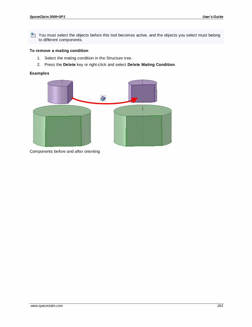
SpaceClaim 2009+SP1 User’s Guide
www.spaceclaim.com 263
You must select the objects before this tool becomes active, and the objects you select must belong to different components.
To remove a mating condition
1. Select the mating condition in the Structure tree.
2. Press the Delete key or right-click and select Delete Mating Condition.
Examples
Components before and after orienting

SpaceClaim 2009+SP1 User’s Guide
www.spaceclaim.com 264
Detailing You can detail your designs to communicate with others or to submit your designs for review with the
tools on SpaceClaim's Detailing tab. With the detailing tools, you can annotate your designs, create drawing sheets, and review changes to designs. You can customize detailing options to conform to standards or create your own custom style.
Detailing tools are grouped into the following ribbon groups:
Orient Quickly display a particular view of your design.
Font Format note text by adjusting the font characteristics.
Annotation Create notes on your design with text, dimensions, geometric tolerances, tables, surface finish symbols, and datum symbols, center marks, center lines, and threads.
Views Add views to a drawing sheet.
Sheet Setup Format a drawing sheet.
3D Markup Create markup slides to illustrate the changes made to a design.
Press Esc, then S to end any detailing action and return to the Select tool.
Annotation
You can annotate your designs, drawings, and 3D markups with notes, dimensions, geometric tolerances,
surface finish and datum symbols, as well as center marks, center lines, and threads. When you create annotations that are attached to the objects in your design, they stay attached, even when you modify those objects using the Design tools. Annotations created on a drawing sheet or 3D markup slide are part
of that sheet or markup only; they do not appear on your design.
Each annotation has properties which you can modify in the Properties panel. When you create the first annotation, it is scaled so that it will be visible when your design is zoomed to its extents in the Design
window. All other annotations use the same scale.
Annotation ribbon group
The Annotation ribbon group contains the following tools:
Use the Dimension tool to create a measured dimension.
Use the Create Note tool to select an annotation plane and enter text onto the plane.
Use the Note Leader tool to connect a note to an object.
Use the Center Line tool to add a center mark on any circle, arc, cylinder end, or sphere, and put
center lines on any cylindrical face.
Use the Surface Finish tool to create a surface finish symbol.
Use the Geometric Tolerance tool to create a geometric tolerance.
Use the Thread tool to create a threaded surface on any cylinder, cone, or hole.
Use the Bill of Materials tool to create and insert a BOM.
Use the Datum Symbol tool to insert a datum symbol.
Use the Table tool to insert a table note.
After you have inserted a Bill of Materials, use the Balloon tool to insert a BOM balloon note.
Click to display SpaceClaim's detailing options.
Press Esc, then S to end any detailing action and return to the Select tool.

SpaceClaim 2009+SP1 User’s Guide
www.spaceclaim.com 265
Creating notes
Use the Create Note tool to annotate your designs, drawing sheets, and 3D markups. You can use this
tool to create and edit notes. You can also project the note onto a sketch or onto a solid. Place the annotation plane on one layer and the note on another layer, then turn off layer visibility for the annotation plane to hide it.
To create a note
1. Select the Create Note tool from the Annotation ribbon group in the Detailing tab.
Mouse over the faces of your design to preview the eligible annotation planes. (In Sketch and Section mode, the sketch grid defines the annotation plane.)
2. Click a face to create the plane on which to place the note.
To create an annotation plane for a cylindrical face, select the cylinder's axis.
If you need to change the annotation plane, right-click and click Select New Annotation Plane from the context menu and select a new annotation plane.
3. Click to place the note on the plane.
4. Enter the text of the note.
Click in the mini-toolbar to insert a symbol into your note at the cursor location.
Click in the mini-toolbar to insert a dynamic field. Dynamic fields include current values from a variety of properties.
You can format the note text, and enter the text by cutting, copying, and pasting the text from other notes or dimension annotations.
5. Adjust the orientation of the note by dragging the rotation handles.
To create a note field
1. Click within the text of the note and place the cursor where you want the field to appear.
2. Right -click to display the mini-toolbar.
3. Click in the mini-toolbar to display the Insert Field window.
The Fields tab displays the properties available for insertion. (Document properties are those that appear in the Properties panel when you click the top-level design in the Structure tree.)
4. Select a value from the Category drop-down to filter the properties displayed in the Fields list.
If you click Selected Object, you can click any object in the Design window or Structure tree to make its properties available.
If you select Formula, you can enter an expression, and include any numeric fields within the
expression.
5. Click a property in the Fields list.
6. Click the Format tab to format the text within the field.
The formatting options are based on the type of the property value. For example, strings can be formatted with upper case, lower case, initial capitals, or title case.
7. Click OK to insert the formatted, dynamic field into the note at the cursor location.
If the field is empty, check to make sure that the property you selected has a value by selecting the appropriate object and viewing the Properties panel.
To copy a note
Ctrl+drag a note to copy it.

SpaceClaim 2009+SP1 User’s Guide
www.spaceclaim.com 266
To edit a note
1. Select the note to move, size, or rotate it.
If you select a single note, you can edit, resize, and rotate the note. If you select multiple notes, you can only move or change formatting.
To move the note box, mouse over the edge of the box until the cursor changes to , then drag the note.
To size the box containing the note, drag the handles of the note box (the white circles).
To rotate the note, drag the rotation handle (the green circle). Press Shift to snap to angular increments.
2. Select the text of the note to reformat it.
Click a field to edit it. Changing the value of a string also changes it in the Properties panel.
3. Modify the note's properties in the Properties panel. Modify the:
Space property to set the size of the note. Select Model Space to size the text based on the actual measurements of the objects in your design. Select View Space to size the text based on the view of the design in the Design window.
Flagnote property to create a border around the note. Select a shape from the drop -down. Enter a value in the Minimum width property to prevent the flag from resizing automatically to fit the content of the note.
To display the text of an annotation and hide the plane
1. Create two layers, one for notes, and one for the annotation planes.
2. Place the note on one layer and the annotation plane on another layer.
3. Turn off the visibility of the layer that contains the annotation plane.
Examples
Changing the Flagnote property
Formatting note text
You can adjust the font, size, style (bold, italic, underline), alignment of the text within the box, and create
superscripts and subscripts using the tools in the Font ribbon group, or by right-clicking the annotation and selecting from the mini -toolbar.
You change the text characteristics for notes, dimensions, and tables at the same time.
Font ribbon group
The Font ribbon group contains the following tools:
Family Select the font family.

SpaceClaim 2009+SP1 User’s Guide
www.spaceclaim.com 267
Size Select or enter a font size.
Select an amount of offset to create a superscript or subscript.
Bold, italicize, or underline the note text.
Left, center, or right-justify the note text.
Set the text direction from left-to-right or right-to-left.
To format text
1. To change the text formatting for an entire note, dimension, or table, select one or more in the Design window. Hold Ctrl to select more than one or draw a box in the Design window.
To change the text formatting for only some of the text in a note, dimension, or table, select only
the text you want to change.
2. Use the tools in the Font ribbon group to format the text.
To create a superscript or subscript, select a preset amount from the Vertical Text Offset
drop-down, or select Custom and enter a custom amount to raise or lower the text.
Creating note leaders
Use the Note Leader tool to create an arrow from your note.
To create a note leader
1. Select the Note Leader tool from the Annotation ribbon group in the Detailing tab.
Mouse over notes on the active annotation plane to see the possible ways to connect the note leader to the note.
2. Click a note's connection point to draw the first segment of the note leader.
Mouse over your design to highlight the geometry to which you can attach the end of the note leader. You can also attach leaders to temporary objects.
3. For a segmented line, click to set each point of the note leader line.
4. End the note leader.
Click a vertex, edge, or face to attach the end of the note leader to it, or double -click to end the
note leader at any point. The end of the note leader is an arrow unless you attach it to a face.
To insert an all-around symbol
Right -click the note leader and select All Around.
To change a note leader's segments
Drag a segment of the note leader line to move it and its surrounding boundary points. Right -click the
note leader and select Add Jog Point to create a new segment.
You can delete note leader line segments by deleting the jog points that border the segment.
To change a note leader's properties
1. Right -click the note leader and select Properties.
2. Modify the Arrow Style, Length, and Width values.
3. Set the All Around value to True to display an all-around symbol. Select False to hide it.

SpaceClaim 2009+SP1 User’s Guide
www.spaceclaim.com 268
To attach a note leader to a virtual sharp
1. Select the Note Leader tool from the Annotation ribbon group in the Detailing tab.
2. Ctrl+click a line.
3. Ctrl+click a converging line.
The head of the note leader is attached to the virtual sharp. You can also drag the virtual sharp’s end point, draw another leader to the virtual sharp, create virtual sharps in cross -section, for
rounds, and between an angled and straight edge.
Examples
A virtual sharp
Attaching to the bottom connection point of a note to create a leader with a jog or shoulder.
Attaching to the center connection point of a note to create a straight leader.
Use the center connection point to create circle flag notes or BOM balloon notes according to the JIS
standard, without a jog or shoulder.

SpaceClaim 2009+SP1 User’s Guide
www.spaceclaim.com 269
Creating dimension annotations
Use the Dimension tool to add a measurement to your design, drawing sheet, or 3D markup.
You can use annotation dimensions with the Pull and Move tools to change your design. See Driving modifications with annotation dimensions.
An annotation plane cannot be moved to a sub-component after you add dimensions because the references would be lost.
You can enable dual dimensions, which will display each dimension in both Metric and Imperial units. See
Units options.
To create a dimension annotation
1. Click the arrow under Dimension in the Annotation group on the Detailing tab and select
Dimension.
2. If you are creating a dimension in 3D, click a face to create an annotation plane on which to place the dimension.
Mouse over the faces of your design to preview the eligible annotation planes. (In Sketch and Section mode, the sketch grid defines the annotation plane.) If multiple objects occur at your cursor location, use the scroll wheel or arrow keys to highlight each one.
To create an annotation plane for a cylindrical face, select the cylinder's axis.
If you need to change the annotation plane, right-click and click Select New Annotation Plane from the context menu and select a new annotation plane.
3. Click an edge or face.
Where you click on a circle determines whether you will measure from the circle's center, near, or far edge. To select the center click the top, bottom, left, or right side of the circle.
4. Mouse over your design to preview the possible dimensions.
5. Click a second object if you want to dimension between two objects.
6. (Optional) Select a dimension orientation in the Options panel. You can also select the orientation
for the first and second reference.
7. Click to create the dimension.

SpaceClaim 2009+SP1 User’s Guide
www.spaceclaim.com 270
To create ordinate dimensions
1. Click the arrow under Dimension in the Annotation group on the Detailing tab and select
Ordinate Dimensions.
2. If you are creating a dimension in 3D, click a face to create the plane on which to place the
dimension.
Mouse over the faces of your design to preview the eligible annotation planes. (In Sketch and Section mode, the sketch grid defines the annotation plane.) If multiple objects occur at your
cursor location, use the scroll wheel or arrow keys to highlight each one.
To create an annotation plane for a cylindrical face, select the cylinder's axis.
If you need to change the annotation plane, right-click and click Select New Annotation Plane
from the context menu. Then right -click the new place and click Set As Annotation Plane .
3. Click a line or edge to set the baseline dimension.
You can use an existing extension line as a dimensioning reference. An extension line is the line
that connects the point to the dimension text. If you select an extension line, the baseline dimension for the extension line's dimension is used.
4. Mouse over the face to see all the possible dimensions.
5. Click a point to place the dimension line.
If you select a face, all of the possible ordinate dimensions will be created.
You can click multiple points to use the same baseline for those dimensions.
The baseline dimension (0) is displayed or hidden based on which detailing standard is selected in the Detailing options.
Automatic jog points are included if ordinate dimensions are too closely spaced. This helps make
them easier to read.
To dimension bodies
1. Click Dimension in the Annotation group on the Detailing tab.
2. Click the Select bodies tool guide on the right side of the Design window.
3. Select the solid body or bodies you want to dimension:
If you select a single body, then the maximum horizontal or vertical dimension is created,
as shown below.
If you select more than one body, then the dimension is created for both solids and is anchored on the side closest to where you click on the solid. You must click on the
Select bodies tool guide before you select each solid, so you click the tool guide an d select the first part, then click the tool guide again and select the second part.
In both of the examples below, the upper part was selected near its top. The lower part was selected near its top in the example on the left and near its bottom in the example on
the right. The mouse arrows indicate where the lower part was selected. You will see a preview of the dimension when you click the tool guide and hover over the second part.

SpaceClaim 2009+SP1 User’s Guide
www.spaceclaim.com 271
If you create the dimension in a section view of a drawing sheet, then the dimension is created on the extents of the body that is visible in the section plane, as shown below.
To edit a dimension annotation
1. Select the dimension annotation to move, size, or rotate it.
To move the dimension note, mouse over the edge of the box with the Select tool until the cursor
changes to , then drag the note.
To size the box that contains the dimension note, drag the handles of the note box (the white circles).
2. Select the text of the note to reformat it.
3. (Optional) Right-click the dimension and select text formatting options from the mini-toolbar.
Click to select a tolerance format, then edit the text of the tolerance.
Click to insert a field. You can select a field type and format from the Insert Field window.
Select from the drop-down to insert a symbol.
4. Click an arrowhead to cycle through alternative leader styles.
You can also right-click an arrowhead and select Arrow Style to select a style for that arrowhead, or select the arrowhead, then select the style for the head in the Properties panel.
5. Click the note leaders to modify them.
You can right-click a leader and select Add Jog Point to add a new point.
6. To change the distance between a dimension extension line and its reference point on the object,
click on the extension line, then hover over the end closest to the object. Drag the red dot to change its distance from the object.
If you cant' see the extension line, hover over the end of the dimension leader, where the line
would be. You will see two red dots that you can drag:
7. Modify the dimension note properties in the Properties panel. Modify the:
Arrow Length and Width properties to set the length and width of the arrowheads
Measurement property to change the measurement type. For example, you may want to display the radius of a hole instead of the diameter.

SpaceClaim 2009+SP1 User’s Guide
www.spaceclaim.com 272
Show Thread Designation to display the diameter or thread designation for an inside thread. You can change the default and see more options in Sheet Metal options.
Precision property to change the number of decimal places.
Upper Limit, Lower Limit, and Type of tolerance property to change the format of the dimension and enter upper and lower tolerance values.
To display the annotation and hide the plane
1. Create two layers, one for notes, and one for the annotation planes.
2. Place the note on one layer and the annotation plane on another layer.
3. Turn off the visibility of the layer that contains the annotation plane.
Examples
Annotations with orientation changed in the Options panel
1. Dimension Orientation set to Aligned
2. Dimension Orientation set to Horizontal
3. Dimension Orientation set to Vertical
4. 1st Reference Orientation set to Horizontal, 2nd Reference Orientation set to Vertical
A dimension annotation with dual dimensions enabled in the Units options
Ordinate dimension annotations

SpaceClaim 2009+SP1 User’s Guide
www.spaceclaim.com 273
Ordinate dimensions for a planar face
Automatic jog points with closely spaced ordinate dimensions
Dimension between virtual points
You can create dimensions from the line between two points or the mid-plane between two lines, even when that line doesn't exist as an edge.
To dimension between virtual points
1. Click Dimension in the Annotation group on the Detailing tab.
2. Select a point (A) as your starting point.
3. Hold Ctrl and select a second point (B).
This creates a virtual line between points A and B, which will be the baseline of your dimension.
4. Select a third point (C).
Now you have a dimension between line AB and point C:

SpaceClaim 2009+SP1 User’s Guide
www.spaceclaim.com 274
If you hold Ctrl when you select point C, the dimension is created between line AB and line BC:
5. (Optional) If you select point C without holding Ctrl, and hold Ctrl to select a fourth point (D), the
dimension is created between line AB and line CD:
6. Click anywhere in the annotation plane to place the dimension.
To dimension to a virtual sharp
1. Select the Dimension tool from the Annotation ribbon group in the Detailing tab.
2. Hold Ctrl and select a line.
3. Hold Ctrl and select a converging line.
The head of the note leader is attached to the virtual sharp. You can also drag the virtual sharp’s end point, draw another leader to the virtual sharp, create virtual sharps in cross -section, for
rounds, and between an angled and straight edge.
4. (Optional) To end the dimension at another virtual sharp,
a. Hold Ctrl and select a line.
b. Hold Ctrl and select a converging line.
5. Click anywhere in the annotation plane to place the dimension.

SpaceClaim 2009+SP1 User’s Guide
www.spaceclaim.com 275
Dimension to a mid-plane line
1. Select the Dimension tool from the Annotation ribbon group in the Detailing tab.
2. Define the mid-plane line:
a. Select a face or edge:
b. Hold Ctrl and select a second face or edge:
3. The mid-plane line is displayed as a gray line, and the beginning of the dimension is attached to
this line.
4. Select the face, edge, or point you want to dimension to.
The end of the dimension is attached to the face, edge, or point.
5. Click to place the dimension annotation.
You can reverse these steps to begin the dimension with an existing line or point and end the dimension with a mid-plane line. You can also dimension between two mid-plane lines.
Examples
A dimension between virtual points

SpaceClaim 2009+SP1 User’s Guide
www.spaceclaim.com 276
A dimension from a mid-plane line to an edge
A dimension between two mid-plane lines
A dimension to the virtual sharp of a chamfered edge
A virtual sharp

SpaceClaim 2009+SP1 User’s Guide
www.spaceclaim.com 277
Creating geometric tolerance annotations
Use the Geometric Tolerance tools in the Annotation ribbon group in the Detailing tab to add a tolerance
to your design, drawing sheet, or 3D markup slide. In SpaceClaim, geometric tolerances are not created automatically. You can enter anything in a geometric tolerance, so we recommend that you read the geometric tolerance tooltips carefully to create intelligent geometric tolerance annotations.
To create a geometric tolerance annotation
1. Click the Geometric Tolerance tool .
2. Click to place the geometric tolerance annotation on the appropriate annotation plane and display the Format tab.
3. Select the characteristic symbol from the Symbol drop-down in the Geometric Tolerance ribbon
group.
4. Click in one of the Tolerance fields and enter any combination of text and modifying symbols from the Symbols ribbon group.
To create multi-row geometric tolerance annotations, select a characteristic symbol, then enter text and modifying symbols in the second row. To combine the two rows so that they have one characteristic symbol, check the Composite Frame option.
5. Press Esc to exit the annotation and close the Format tab.
To display the text of an annotation and hide the plane
1. Create two layers, one for notes, and one for the annotation planes.
2. Place the note on one layer and the annotation plane on another layer.
3. Turn off the visibility of the layer that contains the annotation plane.

SpaceClaim 2009+SP1 User’s Guide
www.spaceclaim.com 278
Datum and surface finish symbols
You can insert datum symbols onto your design, drawing sheet, or 3D markup slide.
To add a datum symbol
1. Select the Datum Symbol tool .
Mouse over the faces of your design to preview the eligible annotation planes.
2. Click to place the datum symbol on the appropriate annotation plane.
3. Enter a letter.
4. Use the Note Leader tool to create the note leader.
To replace a dimension with a datum
1. Click the Datum Symbol tool .
2. Click the dimension text.
To display the text of an annotation and hide the plane
1. Create two layers, one for notes, and one for the annotation planes.
2. Place the note on one layer and the annotation plane on another layer.
3. Turn off the visibility of the layer that contains the annotation plane.
Surface finish symbols
You can insert surface finish symbols onto your design, drawing sheet, or 3D markup slide. Surface
finish symbols move along with the surface they are attached to.
To add a surface finish symbol
1. Select the type of symbol you want to use from the Surface Finish tool drop-down.
Mouse over the faces of your design to preview the eligible annotation planes. If an annotation plane already exists, right-click and select Select New Annotation Plane to choose a different plane.
2. Click a face to place a leader on the plane.
You can click as many faces as you'd like to add leaders to those faces.
3. Click in an empty area of the Design window to place the surface finish symbol.

SpaceClaim 2009+SP1 User’s Guide
www.spaceclaim.com 279
4. Modify the values in the Properties panel. Modify:
Font Size to change the font size for all the text fields on the symbol.
Template to change the number of fields.
Show All Around Symbol to add that symbol to the surface finish symbol.
Type to change the type of surface finish symbol.
5. Enter text or symbols in the field.
You can press Tab to switch between the fields. Right -click and select from the mini-toolbar to insert a symbol.
To display the text of an annotation and hide the plane
1. Create two layers, one for notes, and one for the annotation planes.
2. Place the note on one layer and the annotation plane on another layer.
3. Turn off the visibility of the layer that contains the annotation plane.
Examples
Surface finish symbols using the Standard, Standard 2, and Standard 3 templates
Center marks and lines
You can put a center mark on any circle, arc, cylinder end, or sphere, and you can put center lines on any
cylindrical face on a drawing sheet.
To add a center mark or center line
1. Click the Center Line tool .
2. Click an:
Edge of the end of the cylinder or hole to add a center mark.
Cylindrical face to add a center line.
Sphere to add a center mark.
Examples
Center mark on the end of a cylinder and center line along the face of a cylinder
Center mark on a sphere

SpaceClaim 2009+SP1 User’s Guide
www.spaceclaim.com 280
Threads
Use the Thread tool to create a threaded surface on any cylinder, cone, or hole. Select a thread edge or
face to view its properties in the Properties panel.
The depth of a threaded blind hole on a curved surface is defined as the measured distance from the end of the thread to the closest point on the outer contour of the thread.
To create a threaded surface
1. Click the Thread tool in the Annotation ribbon group on the Detailing tab.
2. Click the edge of a cylinder, hole, or cone.
The threads are indicated as a texture on the surface, and the thread depth is shown when you
view the threaded object in Section mode. An inner thread or outer thread object also
appears in the Structure tree. (Broken threads appear with a small yellow triangle over the icon.)
3. Click the surface to edit the properties of the threaded surface in the Properties panel.
Type: Controls whether threads are selected from a table or entered manually. For cylinder threads, select Standard to select values for the other properties from a drop-
down list. The most likely values are selected by default (next smaller size for external threads, and the next larger size for internal threads). Select Custom to enter offset values. For tapered threads (threads made on conical surfaces) you can only use the
Offse t option.
Series: You can select ISO or UNC.
Size: Select from a list of available sizes in the series you select.
Thread Depth Type : Can be Blind or Full Thread. Full Thread is the default for through holes and Blind is chosen automatically when the thread placement cylinder or cone ends in a plane at a convex edge.
Minor Diameter: The smallest, or inner, diameter of a thread.
Major Diameter: The largest, or outer, diameter of a thread.
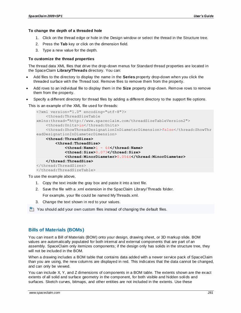
SpaceClaim 2009+SP1 User’s Guide
www.spaceclaim.com 281
To change the depth of a threaded hole
1. Click on the thread edge or hole in the Design window or select the thread in the Structure tree.
2. Press the Tab key or click on the dimension field.
3. Type a new value for the depth.
To customize the thread properties
The thread data XML files that drive the drop-down menus for Standard thread properties are located in the SpaceClaim Library/Threads directory. You can:
Add files to the directory to display the name in the Series property drop-down when you click the threaded surface with the Thread tool. Remove files to remove them from the property.
Add rows to an individual file to display them in the Size property drop-down. Remove rows to remove them from the property.
Specify a different directory for thread files by adding a different directory to the support file options.
This is an example of the XML file used for threads:
<?xml version="1.0" encoding="utf-8"?>
<thread:ThreadSizeTable
xmlns:thread="http://www.spaceclaim.com/threadSizeTableVersion2">
<thread:Units>in</thread:Units>
<thread:ShowThreadDesignationInDiameterDimension>false</thread:ShowThr
eadDesignationInDiameterDimension>
<thread:ThreadSizes>
<thread:ThreadSize>
<thread:Name>1 - 64</thread:Name>
<thread:Size>0.073</thread:Size>
<thread:MinorDiameter>0.0544</thread:MinorDiameter>
</thread:ThreadSize>
</thread:ThreadSizes>
</thread:ThreadSizeTable>
To use the example above,
1. Copy the text inside the gray box and paste it into a text file.
2. Save the file with a .xml extension in the SpacClaim Library/Threads folder.
For example, your file could be named MyThreads.xml.
3. Change the text shown in red to your values.
You should add your own custom files instead of changing the default files.
Bills of Materials (BOMs)
You can insert a Bill of Materials (BOM) onto your design, drawing sheet, or 3D markup slide. BOM values are automatically populated for both internal and external components that are part of an assembly. SpaceClaim only itemizes components; if the design only has solids in the structure tree, they
will not be included in the BOM.
When a drawing includes a BOM table that contains data added with a newer service pack of SpaceClaim than you are using, the new columns are displayed in red. This indicates that the data cannot be changed,
and can only be viewed.
You can include X, Y, and Z dimensions of components in a BOM table. The extents shown are the exact extents of all solid and surface geometry in the component, for both visible and hidden solids and
surfaces. Sketch curves, bitmaps, and other entities are not included in the extents. Use these

SpaceClaim 2009+SP1 User’s Guide
www.spaceclaim.com 282
dimensions to create a cutlist of parts in an assembly of panels in the BOM, along with their number and dimensions. See the instructions for adding a column to a BOM table below.
To add a Bill of Materials to a document
1. Click the arrow next to the Bill of Materials tool in the Annotation group on the Detailing tab and select a type:
Top level: Creates a table that includes only parent components (or parts):
Parts only: Creates a table that includes all child components:
Indented: Creates a table that includes all components, with child components indented:
2. The last type of BOM you created is remembered and will be automatically chosen if you c lick the
BOM icon instead of the drop-down arrow.
3. (Optional) Modify the Bill of Material 's properties in the Properties panel.

SpaceClaim 2009+SP1 User’s Guide
www.spaceclaim.com 283
4. Click to place the Bill of Materials on the design, drawing sheet, or 3D markup slide. The table appears in gray until you place it, and it changes to black after it is placed.
To cancel, press the Esc key before you click to place the table.
The BOM appears in the Structure tree.
You can copy and paste a BOM, and you can copy the contents from a BOM table and paste
them into Microsoft Excel.
To edit a Bill of Materials
When you change a value in a BOM table, the property is changed. You can also select the BOM and edit its properties in the Properties panel.
Drag and drop rows and columns to reorder them.
Select a row or column, right-click, and select from the menu to insert, delete, or merge rows or columns.
Select a row, right-click, and select Split Table from the menu to divide the BOM into two tables, for
example, i f necessary to fit on the drawing sheet.
Resize a table by dragging the circles at its corners or edges.
Rotate a table by dragging the green circle at the top of the table.
To add columns to a BOM table
1. Right -click an existing column and select Insert > Insert Columns to the Left or Insert
Columns to the Right.
2. Select the new column by clicking above the first row of the column, like this:
3. Select a Column Type in the Properties panel.
4. Select a Column Value if you selected Document Property, Material Property, or Custom Property for the column type. The values in the column will be automatically filled-in.
If you select Material Property for the column type and Mass or Volume for the column value,
then the column data will only be filled-in when a material has been assigned to the object.
To export a Bill of Materials
1. Click on a BOM table, then click its edge to select the entire table. The edge will change from a dashed line to a solid line when you have the entire table selected.
2. Right -click the table and select Save Table As.
3. Select HTML or XML for the Save as type.

SpaceClaim 2009+SP1 User’s Guide
www.spaceclaim.com 284
Examples
Selecting a row in the BOM to insert or delete rows, merge cells, or split table
Tables
You can place a table on an annotation plane using the Table tool in the Annotation ribbon group.
You can copy annotation dimensions from drawings and paste them into tables, and their values will be updated when the dimensions change.
To add a table
1. Add an Annotation plane or activate an existing plane.
2. Click the Table tool .
3. Drag to create the table with as many columns and rows as you need. The default cell size is
determined by the font size in the Detailing tab.
To edit a table
Select the table, then drag to select multiple cells. Once multiple cells are selected, you can right -click and select Merge Cells or Unmerge Cells.
Right -click a cell and insert columns and rows.
Select one or more cells and right-click to access the other context menu functions, which allow you to add and remove columns and rows.
Click within a table cell to edit its contents.
Drag a column or row boundary to resize the column or row.
Select rows, columns and cells by positioning the cursor to the left of the row, to the top of the column, and in the internal left side of the cell.
Select and then drag a row or column to move it within the table.
Apply font and paragraph properties to selected text.
Press Tab to navigate through table cells.
Resize a table by dragging the circles at its corners or edges.
Rotate a table by dragging the green circle at the top of the table.
Copy an annotation dimension and paste it into a table cell. The dimension value will be updated automatically if the dimension changes.

SpaceClaim 2009+SP1 User’s Guide
www.spaceclaim.com 285
To move or rotate a table
1. Click the outer, dotted border of the table to select it.
2. Use the:
Arrow keys to move the table.
Ctrl+arrow keys to move the table by a very small amount.
Round handle at the top of the table to rotate the table.
To delete text within a table
1. Select all the cells in the table.
2. Press Delete.
To delete a table
1. Select the table.
2. Select the rectangular border.
3. Press Delete.
To modify table properties
1. Click the outer, dotted border of the table to select it.
2. Enter values in the Properties panel.
You can modify:
Cell alignment and margins.
Position of the table anchor.
Number of rows and columns, column width, and row height.
To copy table contents
Press Ctrl+C or right -click and select Copy. You can paste the data from a table into Microsoft Excel.
Balloon
Use the Balloon tool to add BOM balloon notes. The content of the balloon updates when changes are
made to the BOM table.
The document must contain a BOM table for the Balloon tool to be enabled.

SpaceClaim 2009+SP1 User’s Guide
www.spaceclaim.com 286
To add BOM balloon notes
1. From the drop-down menu on the Bill of Materials tool in the Annotation ribbon group, select a type:
Item number
Part number
Item number and quantity
2. Click a face or edge in the drawing sheet or Design window to attach a balloon to the object.
3. Click again to place the balloon.
To automatically add BOM balloon notes to a view
1. Right -click a view.
2. Select Autoballoon and then Item Number, Part Number, or Item Number and Quantity.
These menu options are only available when a view has a BOM.
Drawing sheets
SpaceClaim helps you create drawing sheets. When you add a new drawing sheet to a design, views of the design are created for you automatically. You can then add, remove, and edit these views, as well as
drag them to move them around on the sheet. Drawing sheets are saved within your design.
Normally, you will create the drawing sheet, set up the sheet, apply a format, add and modify views, then annotate the views.
Drawing sheets and their views appear in the Structure tree. You can place drawing sheet views on layers.
You can edit your design directly while viewing the drawing sheet using the tools on the Design tab.

SpaceClaim 2009+SP1 User’s Guide
www.spaceclaim.com 287
To create a new drawing sheet
Select New > New Drawing Sheet from the application menu.
A drawing sheet containing top, front, and right-side views appears in the Design window, and the Drawing Sheet appears in the Structure tree. The Detailing tab is displayed. You do not need to create a
design before creating a drawing sheet. SpaceClaim allows you to create and edit geometry within the drawing sheet itself. When you create a new drawing sheet for an empty design, the sheet contains the view outlines, with handles you can use to control the size and position of the view. You can delete the
handles and move the view using the outline.
When sketching on a drawing sheet, you can:
Click within the view boundary with a sketch tool to display a sketch grid.
Use the scroll wheel to select a face of a solid in the drawing sheet when only the edge is displayed.
Override colors for solids and surfaces. Changing the colors on the drawing sheet does not affect the colors in the design.
When beginning a design from an empty drawing sheet, you can right -click a design on the drawing sheet
and select Open Component to display the design in a new Design window.
Modifying one view changes the related views as appropriate.
To display a drawing sheet in the Design window
Right -click the sheet in the Structure tree and select Open Sheet.
To delete a drawing sheet
Right -click the sheet in the Structure tree and select Delete.
To change the visual orientation of the drawing sheet
You can orient a drawing sheet using the normal mouse + keyboard combinations and menu commands. For example, you can press the middle mouse button and drag to spin the drawing sheet. See Orienting.
Right -click anywhere in the drawing sheet and select View > Flat View to view the sheet head-on.
Drawing sheets have separate named views in the Views tab. These are the views used to orient your sheet in the design area. The default named views are
Home: Changes the view to head-on by default. Can be set to a different view.
Plan View: Changes the view to head-on based on the face you have selected.
Flat View: Changes the view to head-on for the drawing sheet.
See Customizing views.
To edit design annotations
Right -click the annotation plane in the Structure tree and select Show all dimensions to display any design annotations on that plane. Click an annotation to edit it. Changes made on the drawing sheet will also appear in the design.
To show or hide components in the drawing sheet
Right -click a solid, surface, plane, axis, origin, or thread in a drawing sheet view and select Hide in
Selected View.
The Structure tree displays a mixed visibility state for any objects hidden in a view, as shown in the figure below.
To re-display the object in the view, change the visibility of the object in the Structure tree by clicking the checkbox twice. (If an object is hidden in all the views in a drawing sheet, the Structure t ree displays the visibility as hidden.)

SpaceClaim 2009+SP1 User’s Guide
www.spaceclaim.com 288
Setting up a drawing sheet
You can format the drawing sheet using a template, orient the page, and select a paper size for the sheet.
When you select the format and size of the drawing sheet, SpaceClaim automatically sets the scale, but you can modify it.
Use the following tools in the Sheet Setup group to change a drawing sheet:
Format: Select a default or custom format, or remove the formatting from the drawing sheet with the Format tool.
Orientation: Select a portrait or landscape orientation for the page from the Orientation drop-
down list.
Size: Select the page size from the Size drop-down list.
Scale Scale: Select a scale or type a ratio in the Scale field. For example, enter 1:1 to display views of
your design at actual size. The values listed are the two most common ratios that are smaller and larger than the current scale ratio.
Formatting a drawing sheet
You can apply SpaceClaim formats to your drawing sheet or create your own custom formats. You can show or hide the format lines on the sheet.
To change the format of a drawing sheet
1. Click Format in the Sheet Setup group on the Detail tab.
2. Select a format from the list.
3. (Optional) If you want to use a custom format,
a. Click More Formats near the bottom of the format list.
b. Navigate to the SCDOC file containing the format and click Open.
To remove the formatting from the drawing sheet
Select Remove Current Format from Format tool drop-down.
Create a custom drawing sheet format
1. Create a new drawing sheet.
2. Set the orientation, size, and scale of the drawing sheet.
3. Draw on the drawing sheet using the Sketching and Annotation tools.

SpaceClaim 2009+SP1 User’s Guide
www.spaceclaim.com 289
Tip If you insert fields based on document properties into annotations on the drawing sheet, you can create a drawing sheet format that automatically updates when it is applied to a drawing
sheet in a design.
4. Save the drawing sheet into a support directory.
The drawing sheet appears as a format within the Format tool 's drop-down list.
To create a custom drawing sheet by inserting an AutoCAD file
1. Create a new drawing sheet.
2. Click File in the Insert group on the Design tab.
3. Select AutoCAD files for the Files of Type.
4. Select the Import into drawing sheet option.
5. Browse to locate the AutoCAD file, then click Open.
Working with views
You can add and remove views from the drawing sheet, move them around the sheet, and modify their
properties. You can create general views, projected views, cross-section views, and detail views. These views are all related to the view used to create them, and inherit properties from that view.
To add a view to the drawing sheet
1. Select one of the following tools from the Views ribbon group on the Detailing tab:
General View tool to add a new, independent view.
Projected View tool to create a view projected from one of the other views on the
drawing sheet.
Cross Section tool to create a cross-section view using one of the other views on the
drawing sheet.
Detail View tool to create an enlarged view of a particular area.
2. Click to place the view on the drawing sheet.
3. Press Esc or S to exit the tool.
To add a new, independent view
1. Click the General View tool .
2. Click the drawing sheet to add the view at that location.
To modify a General view
1. Select the view.
2. Modify the values in the Properties panel, or right-click and select a style from the mini-toolbar. Change the:
Orientation to change the orientation of the view to isometric, trimetric, or any side. If you change the orientation of a general view from which projected views were created,
the orientation of the projected views also change.
Rendering mode to change the graphics style for the view. Select Inherit if you want to link the graphics style to the drawing sheet.

SpaceClaim 2009+SP1 User’s Guide
www.spaceclaim.com 290
Scale to magnify or shrink the view. When you change the scale, the Type property changes to Independent from sheet. You can select Linked to sheet to set the scale to
be the same as the scale used for the drawing sheet.
3. You can also adjust the appearance of your design on the drawing sheet by using the:
Snap View tool to correctly position the design.
Move tool to position the design more accurately.
When you modify the orientation of a general view, any views dependent on the general view are oriented simultaneously. Other general views do not change.
To select a view on the drawing sheet
1. Press S to activate the Select tool.
If you are in another tool, press Esc to cancel the current action, then press Esc again to exit the tool and activate the Select tool.
2. Mouse just outside the view on the drawing sheet, or scroll over the design shown in the view
until a dashed box around the view is displayed.
3. Click the box to select the view.
To move a view on the drawing sheet
1. Select the view.
2. Drag the view with the Select tool to move it or click the Move tool and move it with the Move handle.
Projected and cross-section views move together as a group.
To orient the design shown in a view
1. Select the component shown in the view.
2. Select the Move tool on the Design tab.
3. Use the Move handle to orient the component within the view.
Views related to the current view also change their orientation.
To modify a view
1. Select the view.
You can select multiple views to modify the properties they have in common.
2. Modify the view's properties in the Properties panel or right-click and modify the view using the mini-toolbar.
3. Control the visibility of the view in the Structure tree.
Projected views
Projected views show another side of the model.
You can drag drawing views to different sheets in the Structure tree. When you drag a projected or
auxiliary view to a different sheet from its parent, its alignment is changed to independent. The two views will be linked again if you drag it back to the same sheet and align it with the parent view.
You can place a projected or auxiliary view independent of the parent view. Select the view, then select
Independent or Aligned to View for Alignment in the Properties panel.

SpaceClaim 2009+SP1 User’s Guide
www.spaceclaim.com 291
To create an orthogonal projected view
1. Click the Projected View tool on the Detailing tab's Views ribbon group.
2. Click within the view you want to use to create the projected view. Do not click a highlighted edge.
If dotted gray lines do not appear around the view, it is not selected. If this occurs, press Esc and try again.
3. Move your mouse to preview the projected view.
Orthogonal views are created as you move toward the top, bottom, left, and right of the current view.
4. Click to place the view on the drawing sheet.
5. Press Esc or S to exit the tool.
To create an auxiliary projected view
1. Click the Projected View tool on the Detailing tab's Views ribbon group.
2. Mouse over the view until the edge you want to use to create an auxiliary projected view is highlighted, then click.
If dotted gray lines do not appear around the view, it is not selected. If this occurs, press Esc and try again.
3. Move your mouse to preview the projected auxiliary view.
Auxiliary views are created as you move the mouse perpendicular to the highlighted edge.
4. Click to place the view on the drawing sheet.
5. Press Esc or S to exit the tool.
To modify a projected view
1. Select the view.
2. Modify the values in the Properties panel, or right-click and select a style from the mini-toolbar. Change the:
Orientation Type to change the projected view to a General view. This makes the selected view independent of the view used to create it.
Rendering mode to change the graphics style for the view. Select Inherit if you want to link the graphics style to the parent view.
Scale to magnify or shrink the view. When you change the scale, the Type property changes to Independent from sheet. You can select Linked to sheet to set the scale to be the same as the scale used for the drawing sheet.

SpaceClaim 2009+SP1 User’s Guide
www.spaceclaim.com 292
Cross-section views
Cross-section views show a cross-section through your design. To create a cross-section view, you must
already have at least two views: one that will become the cross-section, and another that will be used to set the cross-section plane. You can add a cross-section to any view type.
You can set the cross section type to Total or Area, as illustrated in the image above. A Total cross -
section (top right) displays the design in 3D behind the cross-section plane. An Area cross-section (bottom right) displays a cross-hatched illustration of the object's area at the cross-section. The cross-section plane is identified by the plane marked as A.
To create a new cross-section view
1. Click the Cross Section View tool on the Detailing tab's Views ribbon group.
2. Click the Select Reference Geometry Inside Drawing View tool guide.
3. Set the following options in the Options panel on the left:
Create a Total Cross-Section - Check this option to set the view's section type property to Total. Uncheck the option to set the property to Area. See examples in the image
above.
Arrow Orientation - Choose Horizontal or Vertical for the expected orientation, or choose Through Selected Geometry to orient the arrows based on the highlighted
object.
Placement - Select Create as General View to place the view in any location on the drawing sheet. Select Create as Auxiliary View to link the orientation of the cross-
section view to the view containing the arrows.
You can set these options any time before you position the view.
4. Select the object you want to use to orient the section view.
The new view is created and labeled automatically.
5. Click to position the new section view in your drawing sheet.
6. Press Esc or S to exit the tool.
To convert an existing view to a cross-section view
1. Click the Cross Section View tool on the Detailing tab's Views ribbon group.
2. Click the Select Section View tool guide and select the view you want to convert to a cross-
section.
If dotted gray lines do not appear around the view, it is not selected. If this occurs, press Esc and try again.
3. Set the Create a Total Cross-Section option to set the view's section type property to Total. Uncheck the option to set the property to Area. See examples in the image above.
4. Mouse over a related view to display the cross-section indicator and preview the cross-section.

SpaceClaim 2009+SP1 User’s Guide
www.spaceclaim.com 293
The indicator line snaps to geometry in the view. Geometry in front of the cutting plane is not displayed.
5. Click to place the cross-section indicator and create the cross-section view.
The view is labeled automatically.
6. Press Esc or S to exit the tool.
To modify a cross-section view
1. Move the cross-section indicator to change the cutting plane.
2. Select the cross-section view.
3. Modify the values in the Properties panel, or right-click and select a style from the mini-toolbar.
Change the value in:
Orientation Type to change the cross-section view to a General view. This makes the selected view independent of the view used to create it.
Rendering mode to change the graphics style for the view. Select Inherit if you want to link the graphics style to the parent view.
Scale to magnify or shrink the view. When you change the scale, the Type property changes to Independent from sheet. You can select Linked to sheet to set the scale to
be the same as the scale used for the drawing sheet.
Section Type to create a total or area cross-section. Select Total to display 3D geometry not on the cross section plane. Select Area to display only the geometry on the cross-
section plane. You can select None to turn the view into a General view.
4. Select a region within the cross-section view.
5. Modify the values in the Properties panel. Change the value in the following Cross hatching
properties:
Exclude from sectioning to remove the selected region from the cross-section view.
Fill styles to add or removing hatching from the region.
Angle to modify the angle at which the hatching lines are drawn.
Spacing to modify the space between hatching lines.
Offse t to modify the start point of the first hatching line.
Tool guides
Within the Cross Section tool, there are two tool guides:
Use Select Section View to select the view you want to convert to a cross-section view.
Use Reference Geometry Inside Drawing View to select the object you want to use to
orient the section.

SpaceClaim 2009+SP1 User’s Guide
www.spaceclaim.com 294
Detail views
Detail views allow you to magnify a portion of another view to show more detail. To create a detail view,
you must already have at least one view on your drawing sheet.
If a detail view does not display correctly, make sure that you loaded any lightweight components shown in the view.
You can change several options for detail views in the Detailing options, such as line weights and note options.
To create a new detail view
1. Click the Detail View tool on the Detailing tab's Views ribbon group.
2. Select one of the following options:
Create Detail of Selected View to create a new detail view with the boundary drawn on an existing view.
Convert Selected View to Partial to convert an existing view into the detail view.
3. Select the Sketch Boundary Type (circle, rectangle, or spline) from the Options panel.
4. (Optional) Enter the Scale on the Options panel.
5. Click on the view that will create the detail to set the anchor point for scaling.
Usually, you will create an anchor point very close to the detail that you want to show in the view.
6. Click to set the center of a boundary circle, a corner of a rectangle, or the first point of a closed spline.
7. Click again to define the boundary circle or rectangle, or click multiple times to define the
boundary spline.
The detail view is displayed.
8. Click to place the detail view on the drawing sheet.
9. Press Esc or S to exit the tool.
To modify a detail view
If you created a circular or rectangular boundary, you can drag to expand or shrink it.
Modify the values in the Properties panel, or right-click and select a style from the mini-toolbar. Change
the value in:
Rendering mode to change the graphics style for the view. Select Inherit if you want to link the graphics style to the parent view.
Scale to magnify or shrink the view. When you change the scale, the Type property changes to
Independent from sheet. You can select Linked to sheet to set the scale to be the same as the scale used for the drawing sheet.
Orientation type to change the detail view to a General view.
You can drag drawing views to different sheets in the Structure tree. When you drag a detail view to another sheet it remains linked with its parent view.
3D markup
SpaceClaim allows you to create 3D markup slides so that you can highlight and communicate the differences between versions of a design.
Slides can be exported in PowerPoint and XPS formats.

SpaceClaim 2009+SP1 User’s Guide
www.spaceclaim.com 295
Markup ribbon group
The Markup ribbon group contains the following tools:
Create a new 3D markup slide for the current design with the New Slide tool.
Display the dimensions of the previous version and the current version with the Original Dimension Values tool.
Apply colors to the design that indicate the type of change that occurred with the Color Changed Faces tool.
To create a 3D markup
1. Open the design you want to mark up in the Design window.
2. Select Save As New Version from the Application menu to create a new version of your design.
The new version is saved with a version number appended to the file name, and becomes the active Design window.
3. Make changes to the new version of the design.
4. Select New > 3D Markup from the Application menu to create the first 3D markup slide.
The slide is shown in the 3D Markup panel, the design window, and the Structure tree. In the
Structure tree, the version you created in step 2 is labeled Reference Design.
5. Select the Insert tool from the Design tab and insert a previous version or the original version of the design into the slide.
The design appears in the Structure tree, labeled either Alternate Version or Original Version. In the Design window, the previous version of the design is displayed in the wireframe transparent style and is placed directly on top of the new version. The Move tool is active.
6. (Optional) Move the alternate version to a new location by clicking on a Move handle axis and dragging.
7. Customize the slide using the tools in the Markup ribbon group in the Detailing tab.
You can document the dimension changes with dimension annotations, color the faces based on the type of changes made, and apply any other annotations using the tools in the Annotation ribbon group in the Detailing tab. You can right -click a lightweight component and select Load
Component to load it.
8. Create as many slides as you need to effectively communicate your changes.
You can right-click a slide in the Structure tree and select Open Slide to display the slide.
9. Select Save As XPS or Save As PowerPoint from the Application menu to export the 3D markup slides to a separate document.
Examples

SpaceClaim 2009+SP1 User’s Guide
www.spaceclaim.com 296
Structure tree shows contents of each slide. 3D Markup panel shows two slides in the slide show. Design window shows reference and original versions compared with dimensions and coloring for changed faces.
Creating 3D markup slides
Use the New Slide tool in the Markup ribbon group on the Detailing tab to create a new 3D markup slide.
To create a 3D markup slide
1. Select the New Slide tool or right-click in the 3D Markup panel and select New Slide from
the context menu.
A new 3D markup slide appears in the 3D Markup panel containing the reference design. (The reference design is the design that was active when you first created the 3D Markup document.
2. Insert a previous version of the design for comparison.
Displaying changed dimensions
Use the Display Original Dimension Values tool to create dimension annotations for the current and
original dimensions in the 3D markup slide.
To display changes to dimensions
Create dimension annotations on the new version with the Dimension tool.
The original dimension appears as a "Was" value alongside the current one, if that dimension changed
between the two versions.
To edit a change dimension
Click within the dimension and edit the text or formatting.
You can copy and paste the dimensions into a note or table.
You can also delete either the original or new value. If you delete the original dimension, and then want to
restore the change dimension, select the annotation and click the Original Dimension Values tool from
the Markup ribbon panel on the Detailing tab. To restore the change dimension to all annotations, click
the Original Dimension Values tool with no annotations selected.

SpaceClaim 2009+SP1 User’s Guide
www.spaceclaim.com 297
Coloring changed faces
Use the Color Changed Faces tool in the Markup ribbon group on the Detailing tab to automatically color
the faces that changed from one version to another based on the nature of the change.
We recommend creating a legend on your slide similar to the following to help communicate the meaning of each color:
New faces are colored green. Green faces did not exist in the previous version and will appear only on the modified version of the design.
New topology is colored blue. Blue faces have changes to both the face and its edges, but the
face existed in the previous design.
Deleted faces are colored red. Red faces will appear only on the previous version of the design.
Faces with changed edges are colored pink. Pink faces are in the same spatial location, but are bounded differently because their edges have changed.
Faces with a changed spatial location are colored yellow. The edges of yellow faces have not changed from the previous version.
If you want to manually color the faces, you can apply colors to the individual faces on your 3D Markup
slide.
To temporarily color changed faces
Click the Color Changed Faces tool . Click again to remove the colors.
The colors are shown on the current slide.
Setting detailing options
You can customize the style of your annotations in a single design or set a custom style as the default for all designs. You can quickly customize the style to conform to ASME or ISO/JIS standards, or you can create a style by customizing note leaders, dimensions, and geometric tolerances.
To change detailing options
1. Select SpaceClaim Options from the Application menu and click Detailing or click in the Annotation ribbon group on the Detailing tab.
To customize the new window font
a. To change the default font, select any font that is installed on your system from the New window font list.
b. This font will be used as the default font for all new windows. When a new window is
created for an old or new document, this font will be used. It will also be used for new SpaceClaim sessions.
To customize the default graphics style for drawings
a. Select SpaceClaim Options from the Application menu and click Detailing or click in the Annotation ribbon group on the Detailing tab.

SpaceClaim 2009+SP1 User’s Guide
www.spaceclaim.com 298
b. Select Shaded, Wireframe, Hidden Line, or Hidden Line Removed from the Default drawing graphics style list.
This option only sets the default for the Graphics tool found on the Display tab; you can change it for individual objects using the tool.
To customize the paper size and format
a. Select SpaceClaim Options from the Application menu and click Detailing or click in the Annotation ribbon group on the Detailing tab.
b. Select one of the following:
Use external format to select a pre-defined format provided by SpaceClaim or click Browse to select a custom format from any SpaceClaim file.
No format to use blank drawing sheets of a size and orientation that you set. Select Standard to choose from a list of standard paper sizes and orientations,
or select Custom to define your own paper size.
To set all Document options to ASME, ISO, JIS, or CB standards
a. Select SpaceClaim Options from the Application menu and click Detailing or click in
the Annotation ribbon group on the Detailing tab.
b. Select one of the following from the Detailing options for drop-down list:
All New Documents to create a default detailing style for all your designs.
This Document to set options for the current design only.
c. To set all Document options to the following standards:
Click Reset to ASME Default to customize annotations for ASME systems.
Click Reset to ISO Default to customize annotations for ISO systems.
Click Reset to JIS Default to customize annotations for JIS systems.
Click Reset to CB Default to customize annotations for JIS systems.
JIS defaults are the same as ISO, except that JIS uses third-angle views while ISO uses first-angle views. (A third-angle view is labeled by the object. Therefore, the front of the
object is the "Front view" in JIS. A first-angle view is labeled by the direction you are looking. For example, if you are looking front, you see the back of an object. Therefore, the back of the object is the "Front view" in ISO.)
To customize General views
a. Select SpaceClaim Options from the Application menu and click Detailing or click in the Annotation ribbon group on the Detailing tab.
b. Modify the Default view projection. Select:
First Angle to label the view by the direction you are looking. For example, if you are looking front, you see the back of an object. Therefore, the back of the object
is the "Front view."
Third Angle to label the view by the object. For example, the front of the object is the "Front view."
c. Modify the Default front view position. Select:
Top left to place the front view at the top left corner of the drawing sheet. This is the ISO standard.
Top right to place the front view at the top right corner of the drawing sheet
Bottom left to place the front view at the bottom left corner of the drawing sheet. This is the ASME and JIS standard.

SpaceClaim 2009+SP1 User’s Guide
www.spaceclaim.com 299
Bottom right to place the front view at the bottom right corner of the drawing sheet. If you use third angle projection, ISO standards also allow this position.
To customize Cross Section views
a. Select SpaceClaim Options from the Application menu and click Detailing or click in the Annotation ribbon group on the Detailing tab.
b. Modify the following settings:
Section line arrow size - Enter a value to set the size of the arrow shown on the end of the section indicator.
Section line length - Enter a value to set the length of the section indicator.
Section cut line extension distance - Enter the length of the arrows that extend from the section indicator.
Section line arrow direction - Select whether you want the arrows to point toward or away from the section indicator.
Trim back section cut line interiors - Check this box, then enter the length of the section line you want to appear connected to each arrow.
Default section name note prefix - Select how you want the section label to
appear on the drawing sheet.
To customize Detail views
Modify the following settings:
Detail view name text height ratio - Set the ratio of a character's height to width. For example, a value of 1.4 sets the character height to 140% of its width.
Default view note layout - Select One Line to display the detail name and scale on one line. Select Two Lines to display the scale below the detail name.
Default detail name note prefix - Select how you want the detail label to appear on the drawing sheet.
Default view scale note prefix - Select how you want the scale label to appear on the
drawing sheet.
Detail view boundary note placement - Select how you want the detail name and scale information to be positioned relative to the detail boundary.
To customize the display of threaded surfaces
Select a value from the Cosmetic thread display standard drop-down.
ASME Simplified is the same as ISO and JIS Conventional display standards.
To customize annotation options
Modify the following settings in the Annotation Options area:
Default text height - Enter the height of the annotation text.
Leader circle size - Enter the size of the circle that connects note leaders to faces.
Leader arrow length - Enter the length of the arrow on note leaders.
Leader arrow width - Enter the size of the arrowhead on note leaders.
Leader shoulder length - Enter the length of the line from the note text to the note leader arrow.
Leader textbox gap - Enter the size of the margin between the note text and the beginning of the note leader.
Center line extend- Enter the length that a center line will extend past the edge of the object.

SpaceClaim 2009+SP1 User’s Guide
www.spaceclaim.com 300
Default arrow fill style - Select the style you want to use for the arrowheads on note leaders from the drop-down list.
Default dimension text location - Select how you want to align the note leader text with the note leader line from the drop-down list.
Default GTOL font name - Select the font you want to use for geometric tolerance symbols from the drop-down list. The two fonts in this drop-down list contain all the geometric
tolerance symbols necessary. These symbols will be used as necessary in annotations, even when you select a different font for the annotation text.
Virtual sharps rendering style - Select the symbol you want to use to indicate the virtual
sharp.
Datum symbol frame - Select the frame style for datum symbols.
Datum symbol attachment - Select the attachment style for datum symbols.
Show thread designation in thread diameter - Choose whether thread designations are
shown instead of thread diameters:
o Never: Show the diameter and not the thread designation.
o Always: Show the thread designation instead of the diameter.
o Per thread table: Use the value for ShowThreadDesignationInDiameterDimensions in the thread table XML file. The
value can be set to true or false.
o If units match: Show the thread designation if the system units match the units from the thread table.
o Per thread table if units match: Show the thread designation if the units match and if
the ShowThreadDesignationInDiameterDimensions value is true.
Enforce dimension line - Check the box to use the European standard of keeping the
dimension line when the extension lines are shown.
Tight gap between dimension line and text - Check the box to shrink the gap between the dimension text and witness lines.
Horizontal dimension text - Check the box to keep all annotation text oriented horizontally.
Override layer color for annotations - Check the box to set all annotation text to the color selected shown in the Annotation color control. If you choose to override the layer color, select the color used for the override from the Annotation color control.
Extension line gap - Enter the size of the margin between geometry and the end of dimension lines.
Extension line extend - Enter the length that the dimension lines cross each other.
Dimension line extend - Enter the length of the arrow that appears outside the dimension
lines.
Dimension text offse t - Enter the distance between the dimension text and its leader line.
Show zero value for base ordinate dimension - Display the baseline dimension as a 0.
Show common dimension line for ordinate dimensions - Display all dimensions along the
same line. Check Rotate text if you want the dimensions to be displayed along the line instead of perpendicular to the line.
To customize line styles
Modify the following settings in the Linestyle Options area:
Default thick lineweight - Enter the default width for thick lines.
Default thin lineweight - Enter the default width for thin lines.

SpaceClaim 2009+SP1 User’s Guide
www.spaceclaim.com 301
Select an object type, then select the Line style and Thickness for that object.
The values in the Trim back section control the line weight for side offset handles.
Thick-Empty-Thick lines look like this:
Thick-Thin-Thick lines look like this:
If you try to enter a value that is out of the allowed range in the Options panel or the SpaceClaim Options dialog, you will see a red exclamation mark icon next to the field. You can hover over the
icon to see a tooltip that will explain the valid values for the option.

SpaceClaim 2009+SP1 User’s Guide
www.spaceclaim.com 302
Displaying your design The tools you use to customize the appearance of your design within the design window are found on
SpaceClaim's Display tab.
Customize your design by modifying which objects are displayed, the style in which solids and edges are displayed, and the color in which solids appear in your design.
Create layers to save different customizations and display characteristics.
Customize the workspace by creating windows or splitting the window to display multiple views of your design.
Show or hide workspace tools.
Configure the docking/detached location of all your workspace windows.
Create views to save the camera perspective and assign the view to a hotkey.
Display tools are grouped into the following ribbon groups:
Orient Quickly display a particular view of your design.
Style Determine how the solids in your design will be displayed.
Window Create new design windows, split windows, and quickly switch between windows.
Grid Determine how the sketch grid and the geometry above or below the grid is displayed
Show Display or hide tools in the Design window.
Showing and hiding objects
You can use any of these methods for setting the visibility of objects in the Design window:
Right -click an object in the Design window and select Isolate to view only that solid, surface, or curve.
Right -click anywhere in the Design window and select Show All to make all objects visible.
Right -click an object in the Structure tree and select Always Visible from the context menu. The object will remain visible if you hide its layer, but this setting has no effect on other visibility commands such as Isolate or hiding its parent component by deselecting its check box it in the Structure tree.
Deselect the check box in the Structure tree to hide the object in the Design window. The object icon is displayed in gray. You can also right-click an object in the Design window and select Hide (or select it in the Design window and press Ctrl+H) to turn the visibility of the object off.
Select the check box next to the object in the Structure tree to set the visibility of the object to the layer visibility. If the layer is hidden, then the object will be hidden. If the layer is visible, then the object will be visible.
If the layer visibility is on, the icon appears normally. If the layer visibility is off, the icon appears like the Solid_LayerHidden icon in the figure above. You cannot work with hidden objects in the Design window.
Shift+click and Ctrl+click multiple objects to work with them as a group.

SpaceClaim 2009+SP1 User’s Guide
www.spaceclaim.com 303
Orienting designs Select a tool from the Orient ribbon group to orient your design in the workspace. You can use these tools
at any time, even when you are designing with other 2D or 3D tools.
Drag the middle mouse button to spin, Shift+drag it to pan, and Ctrl+drag it to zoom. You can switch between spinning, panning, and zooming by pressing and holding Ctrl (to zoom) or Shift (to pan).
When you release the key, you will return to spinning.
Orient ribbon group
The Orient ribbon group contains the following tools:
Use the Home tool to return the orientation of your design to the default, trimetric view. You
can customize the Home view to show your design with any orientation, location, and zoom level.
Click the Plan View tool to display a head-on view of the sketch grid or the select plane or
planar face.
You can use the Spin tool to re-orient your design in any direction. Spinning your design allows you to view it from any angle.
Use the Pan tool to move your design within the Design window.
Use the Zoom tool to display your design closer or farther away in the Design window. You can zoom the design to fill the Design window, zoom into an area, or zoom in or out a preset amount.
Use the View tool to display a trimetric or isometric view of your design. You can also display a head-on view of the top, bottom, front, back, right, or left side.
Use the Snap View tool to display a head-on view of a face. You can also use the tool to
"throw" the highlighted face to the top, bottom, right, or left by dragging it toward the edge of the Design window.
Use the Rotate tool to rotate your design 90 degrees in the plane of the screen. You can rotate your
design clockwise or counterclockwise.
Use the Next and Previous arrows (or left/right arrows on your keyboard, or browser
next/previous buttons) to change your view to the previous or next orientations.
Orient modes
When you click the Spin, Pan, and Zoom tools, they stay enabled until you click them again, press Esc, or click another tool.
Undoing and redoing views
You can undo and redo views using the Previous View and Next View tools on the status bar.
You can also use the left and right arrow keys, or any system-defined browser forward or back method such as special keyboard buttons.
Spinning your design
You can use the Spin tool to re-orient your design in any direction. Spinning your design allows you to view it from any angle. SpaceClaim uses standard arc -ball rotation; your design spins as if you could grab it with the cursor and adjust it like a real object.
When you click the Spin tool, it stays enabled until you click it again, press Esc, or click another tool.

SpaceClaim 2009+SP1 User’s Guide
www.spaceclaim.com 304
To spin your design
1. Click Spin in the Orient group on the Design tab or in the status bar.
You can also select one of the following from the Spin drop-down:
On Center to spin around the center of your design.
On Cursor to spin around the cursor location.
2. Click and drag to spin your design.
If you start dragging on a highlighted line, edge, or axis, you can rotate your design around it. You can remove this feature by setting the advanced SpaceClaim option Rotate about preselected object in spin. (Press Alt and drag to rotate around a highlighted object whether or not this
option is selected.)
You may find it easier to reach a desired orientation if you use short mouse drags to spin the design a little bit at a time.
If you double-click a face while using the Spin tool, the face is zoomed so that it fills the design window.
Set the Rotate about preselected object in spin option. Then, when working in any tool, position
the middle mouse button on the face, edge, plane, or axis about which you want to spin your design, and drag to spin.
To set the spin center
Right -click anywhere in the Design window, select Spin Center, and select one of the following:
Set: Sets the spin center to the center of the object you have selected. If you don't have an object selected, the spin center is set to the spot where you right-click. If you previously set the spin center, setting it again will change it to your current selection. You don’t need to clear the spin center to set it again.
Clear: Clears the spin center. When you rotate your view in 3D, the spin will be centered based on the option you select in the Spin tool.
Locate: Centers the view on the spin center, if one is set.
To display the spin center indicator
Select Spin Center in the Show group on the Display tab to see an indicator of your spin center in the Design window when you spin your view. The indicator only appears while you spin, and it changes when you have a spin center set. The default indicator is shown below on the left. The indicator below is shown
when you have the spin center set.
Panning your design
Use the Pan tool to move your design within the Design window.
When you click the Pan tool, it stays enabled until you click it again, press Esc, or click another tool.
To pan
1. Select the Pan tool from the Orient ribbon group or status bar.
2. Drag to move your design around the Design window.
If you double-click a face while using the Pan tool, the face is zoomed so that it fills the design window.

SpaceClaim 2009+SP1 User’s Guide
www.spaceclaim.com 305
When working in any tool, Shift+click the middle mouse button and drag to move your desig n.
Zooming in and out
Use the Zoom tool to display your design closer or farther away in the Design window. You can zoom the design to fill the Design window, zoom into an area, or zoom in or out a preset amount.
When you click the Zoom tool, it stays enabled until you click it again, press Esc, or click another tool.
To zoom in and out
1. Select the Zoom tool from the Orient ribbon group or status bar.
2. Click where you want to center the zoom.
3. Drag down to zoom into your design; drag up to zoom out.
You can also use the scroll wheel to zoom in and out.
When working in any tool, Ctrl+click the middle mouse button, then drag up and down to zoom. You
can also press Ctrl+ or Ctrl- to zoom in or out a preset amount.
To zoom the design or a selected face or edge to fit the Design window
Select Zoom > Extents or press Z.
The design or selected face or edge is zoomed so that it fills the Design window. When working with a
drawing sheet, it will fit the drawing sheet to the Design window. If you resize the Design window, the design will also be resized until it again fills the Design window.
To zoom into a selected area
1. Select Zoom > Zoom Box In.
You can also right-click in the Design window and select View > Zoom Box In from the menu.
2. Click and drag to select the area.
Two rectangles appear as you draw. The dotted rectangle shows your selection; the solid
rectangle shows what will be displayed in the Design window. When you mouse -up, the design pans and zooms until it fits within the area.
To zoom in and out a preset amount
Select Zoom > Zoom In to bring your design closer. Select Zoom > Zoom Out to move your design
further away.
When working in any tool, press Ctrl and + or Ctrl and - to zoom in and out a preset amount.
Rotating your design
Use the Rotate tool to rotate your design 90 degrees in the plane of the screen. You can rotate your design clockwise or counterclockwise.
To rotate your design 90 degrees
Click the Rotate tool .
To change the rotation direction
Select Rotate > Rotate 90 Counterclockwise .

SpaceClaim 2009+SP1 User’s Guide
www.spaceclaim.com 306
Your design rotates 90 degrees counterclockwise and the Rotate tool icon changes to . Clicking the
Rotate tool will continue to rotate in the counterclockwise direction.
Select Rotate > Rotate 90 Clockwise to rotate your design in the clockwise direction and set the Rotate tool to rotate clockwise.
The Home view
Use the Home tool to return the orientation of your design to the default, trimetric view. You can
customize the Home view tool so that it displays your design with a specific orientation, location, and zoom level.
Compared to the isometric view, the trimetric view orients your design so that the front face is angled
slightly towards you and less of the top is shown. The isometric view is on the left and the trimetric view is on the right.
To display the Home view
Click the Home tool in the Orient ribbon panel or press H.
To customize the Home view
1. Use the other Orient tools to set up a view of your design in the workspace.
2. Select Home > Set As Home View to make the view in the active Design window the Home view.
Now, when you click the Home tool, your custom view is displayed. Your home view is saved with your design.
Click Home > Reset Home View to return the Home view to the default, trimetric view.
Display a head-on view of the sketch grid
Click the Plan View tool in the Orient ribbon group or in the Sketching mini-toolbar to display a head-on
view of the sketch grid or the selected plane or planar face.
If this tool is disabled, select a plane or planar surface or display the sketch grid.
Selecting a view
Use the View tool to display a trimetric or isometric view of your design. You can also display a head-on view of the top, bottom, front, back, right, or left side. Your design's orientation in the head-on views is
determined by SpaceClaim's default coordinate system.
Compared to the isometric view, the trimetric view orients your design so that the front face is angled slightly towards you and less of the top is shown. Compare the two views in the image below. The
isometric view is on the left and the trimetric view is on the right.

SpaceClaim 2009+SP1 User’s Guide
www.spaceclaim.com 307
To select a view
Select the view you want from the View tool menu in the Orient ribbon group.
To display a trimetric or isometric view of your design
Select Trimetric or Isometric from the View tool menu.
To display a head-on view of your design
Select Top, Bottom, Front, Back, Right, or Left from the View tool menu.
Snapping to a view
Use the Snap View tool to display a head-on view of a selected face or plane. You can also use the tool to throw the highlighted face or plane to the top, bottom, right, or left. On a drawing sheet, flipping one view also flips all related views.
Snap View works on objects with a direction: planes, datums, cones, torii, curves and edges. For non-linear curves, the direction is determined by the direction between the endpoints.
You can only use this tool in 3D mode; it is disabled in Sketch and Section modes.
To snap the view
1. Click Select or press S.
2. Click Snap View in the Orient group.
3. Use objects in the Design window to orient your view:
Click and release on a plane, point, cone, torus, curve, or edge.
If the object is not oriented head-on, then it will rotate so the face you click is viewed head-on, like this:
w
If the object is already oriented head-on, then it will rotate 90° counter-clockwise or it will
rotate so it is square with the Design window, like this:

SpaceClaim 2009+SP1 User’s Guide
www.spaceclaim.com 308
Click, drag, and release a plane, point, cone, torus, curve, or edge to throw it up, down, left, or right.
If the object is not oriented head-on, then it will rotate so the face you click is viewed head-on and square with the Design window, like this:
If the object is oriented head-on, it will rotate 90° in the direction you drag, like this:
Click anywhere in empty space to rotate the view 90° counter-clockwise, like this:
4. Repeat until you see the view you want.

SpaceClaim 2009+SP1 User’s Guide
www.spaceclaim.com 309
Applying a graphics style SpaceClaim offers several different ways to style your design. You can apply styles to your entire design
or drawing sheet, to individual layers, or to individual views in your drawing sheet.
To apply a graphics style to your design
Select an option from the Graphics Style tool from the Style ribbon group on the Display tab to
display your design with that option.
Select the option that works best for you for any given task. You can display geometry with a shaded or
perspective shaded style, as wireframes, as wireframes with hidden lines displayed in light gray, and as wireframes with hidden lines removed. We recommend that you use the shaded style to most clearly indicate the difference between solids and surfaces.
To set a solid or surface to be transparent, opaque, or metallic
1. Select the solid or surface.
2. Select Transparent, Opaque, or Metallic from the Face Style drop-down to apply that surface
style to the selected solid or surface.
If you apply the Opaque style to a surface, it will be returned to the transparent style if it becomes part of a new surface, such as after a merge.
Examples
Transparent Opaque Metallic
Displaying edges
Use the Edges tool to customize which edges are displayed. These settings are saved with the document, but are only used for 3D display. The edge display options apply to the design in the current Design window tab, and not other designs you may have open in other tabs in the Design window.
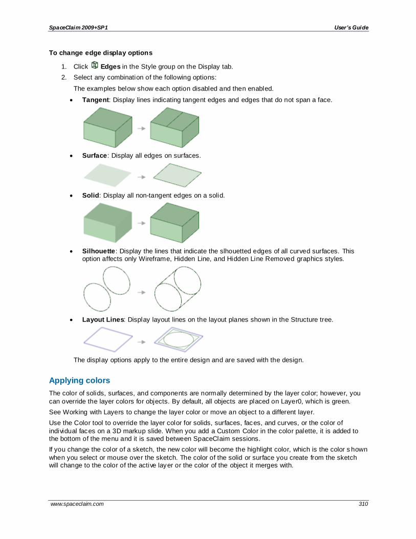
SpaceClaim 2009+SP1 User’s Guide
www.spaceclaim.com 310
To change edge display options
1. Click Edges in the Style group on the Display tab.
2. Select any combination of the following options:
The examples below show each option disabled and then enabled.
Tangent: Display lines indicating tangent edges and edges that do not span a face.
Surface: Display all edges on surfaces.
Solid: Display all non-tangent edges on a solid.
Silhouette: Display the lines that indicate the slhouetted edges of all curved surfaces. This option affects only Wireframe, Hidden Line, and Hidden Line Removed graphics styles.
Layout Lines: Display layout lines on the layout planes shown in the Structure tree.
The display options apply to the entire design and are saved with the design.
Applying colors
The color of solids, surfaces, and components are normally determined by the layer color; however, you
can override the layer colors for objects. By default, all objects are placed on Layer0, which is green.
See Working with Layers to change the layer color or move an object to a different layer.
Use the Color tool to override the layer color for solids, surfaces, faces, and curves, or the color of
individual faces on a 3D markup slide. When you add a Custom Color in the color palette, it is added to the bottom of the menu and it is saved between SpaceClaim sessions.
If you change the color of a sketch, the new color will become the highlight color, which is the color s hown
when you select or mouse over the sketch. The color of the solid or surface you create from the sketch will change to the color of the active layer or the color of the object it merges with.

SpaceClaim 2009+SP1 User’s Guide
www.spaceclaim.com 311
By default, imported models retain their original colors. You can change the options so imported models are set to SpaceClaim color tones, which are less saturated and are usually easier to work with because
selected objects are highlighted in a darker color. See File options.
The Color tool shows the color for new objects and a layer icon is displayed in the tool i f the color is set by the active layer. You can change the color when you don't have anything selected and the color will
become the default for new objects outside of the layer structure. This allows you to set the color for things you haven't created yet, without using layers and default layer colors.
To override the layer color of a solid, surface, face, or curve
1. Select one or more solids, surfaces, faces, curves, or components in the Design window or
Structure tree.
Hold the Ctrl key to select more than one object.
If you select a component, then the color of all of the component's children will be changed.
2. Select a color from the Color tool on the Display tab's Style ribbon group. The Color tool is shown in the image above.
If the color you want is not in the list, select Custom Color and select a color.
To reapply the layer color
1. Select one or more solids, surfaces, faces, or curves in the Design window or Structure tree.
Hold the Ctrl key to select more than one object.
2. Select Remove Color Override from the Color tool on the Display tab's Style ribbon group. You
can see this option in the image of the Color tool above.

SpaceClaim 2009+SP1 User’s Guide
www.spaceclaim.com 312
Line styles
You can apply a custom line style and line weight to the lines in your designs and drawing sheets. The
line styles you choose apply to annotations, center marks, center lines, and drawing sheet cross-section view arrows, hatching, hatched area borders, and detail view boundaries. You can apply line styles to individual objects or to all the objects on a layer. The width that you set is exactly the width that will be
printed when you print an unscaled drawing sheet.
You can set the default line styles for various objects in the SpaceClaim options. Setting the line styles individually overrides the default setting.
Line styles can be assigned to layers so that you can have different line styles for sketch and layout lines.
To apply a line style
1. Select the objects or layer to which you want to apply the line style.
2. Select the line style from the Line Style tool menu.
3. Select the line weight from the Line Weight tool menu.
Displaying your design in multiple windows
Use the New Window tool to create new workspace windows. Creating multiple windows allows you to set
up several views of your design. Each window has a numbered tab at the bottom of the workspace.
To create a new workspace window
Select the New Window tool on the Display tab's Window ribbon group.
A new tab appears at the bottom of your workspace and a number is appended to the design, drawing sheet, or 3D markup name. You can click the middle mouse button on the tab of any design, drawing
sheet, or 3D markup window to close that window
Splitting the workspace window
Use the Split Window tool to divide the workspace window into multiple windows. Splitting the window
allows you to see multiple views of your design simultaneously.
Select how you want to split the workspace window from the Split Window tool menu on the Display
tab's Window ribbon group. The window is split based on your selection.

SpaceClaim 2009+SP1 User’s Guide
www.spaceclaim.com 313
Switching between windows in the workspace
If you have more than one window open, you can select the window you want to display from the tabs at
the bottom of the workspace.
If you have many windows open and the tabs do not fit in the workspace, you can use the Next Window and Previous Window arrows at the bottom of the workspace to switch between windows.
You can also use the Switch Window tool to select the window you want to display. Select the windo w
you want to display from the Switch Window tool menu on the Display tab's Window ribbon group.
Maximizing the Design window
Press F11 to maximize the design window to full screen. You can still switch between windows and use
the tool guides when the window is maximized.
Press F11 to return to the standard user interface.
Displaying workspace tools
You can adjust the display of workspace tools and the display of your design in the Design window using the tools in the Show ribbon group on the Display tab, and by modifying SpaceClaim options.
To customize the tools displayed while you are working with your design
SpaceClaim offers the following tools on the Show ribbon group on the Display tab to assist you while
creating, editing, and detailing your designs:
Check the World Origin box to display the axes that set the default orientation of the design in the Design window.
Check the Spin Center box to mark the center of the spin when using the Spin tool. (This is the same as the Show Spin Center SpaceClaim option.)
Check the Offset Baseline Faces box to display offset relationships with blue shading.
Check the Coaxial Face Groups box to display faces that share an axis with blue shading.
Check the Lineweight box to switch the line style of lines (such as those displayed in Hidden Line, Hidden Line Removed, and Wireframe graphics styles) from thin to the thickness set by the Lineweight tool in the Style ribbon group.

SpaceClaim 2009+SP1 User’s Guide
www.spaceclaim.com 314
Check the Adjacent Entities box to display faint highlighting on adjacent faces when you hover over an edge and on adjacent edges when you hover over a vertex. Scrolling the mouse wheel switches
between adjacent entities. This feature is useful in selecting the correct edge or face to extrude.
To display other workspace tools, modify the settings in the Popular SpaceClaim options.
You can also display journal -related tools by checking the Show Journal Tab option in the Popular
SpaceClaim options.
Examples
Hovering over an edge with Adjacent Entities highlights the faces shared by the edge
Sketch grid styles
You can modify whether the sketch grid is displayed, and how the geometry above or below the grid is displayed in each Design window. You may want to use one style when you are examining a component, and another when you are creating new geometry within a component. You can further customize the
sketch grid by hiding section lines and faces using SpaceClaim options.
To show or hide the sketch grid
Check the Show Sketch Grid box in the Grid ribbon group on the Display tab to display the sketch grid. The sketch grid appears in all the sketching tools. Displaying the sketch grid allows you to snap to grid
lines and provides a visual cue to the orientation of your sketch within your design
To determine how geometry above or below the grid is displayed
1. Check the Fade Scene Under Grid box to make the geometry under the sketch grid more transparent.
2. Check the Clip Scene Above Grid box to hide the geometry above the sketch grid.
To clip your design with a plane
Right -click a plane and select Clip with Plane. To restore the view of your design, right-click the plane and select Clip with Plane again.
Planes, axes, and annotations are not clipped.

SpaceClaim 2009+SP1 User’s Guide
www.spaceclaim.com 315
Examples
Examining a section with the scene clipped above the grid
Sketching on a cross-section with the scene faded below the grid

SpaceClaim 2009+SP1 User’s Guide
www.spaceclaim.com 316
Displaying lightweight components
Lightweight components are a graphics-only representation of a design. You can adjust the transparency
of the lightweight components in your design. If you do not see lightweight components when you open or insert a design, make sure your settings are configured to display them.
See also Lightweight components.
To adjust the transparency of lightweight components
1. Click the Transparency icon on the status bar.
2. Adjust the slider to set the opacity of the lightweight components in the Design window. All lightweight components are displayed with this opacity.
To make a lightweight component appear solid
Select a lightweight component and press Ctrl+Shift+F8 to make the component appear solid. All other lightweight components still appear dim.
Before dimming, the lightweight components appear slightly transparent and their edges aren't displayed.
After dimming, all components regardless of lightweight status, become dim except the selected lightweight component.

SpaceClaim 2009+SP1 User’s Guide
www.spaceclaim.com 317
Measuring and analyzing The Analysis tab contains the tools you use for measuring, displaying interference, and analyzing quality
in your design.
The analysis tools are grouped into the following ribbon groups:
Measure Tools for displaying measurements of the edges, faces, and solids in your design.
Interference Tools for displaying edges where solids intersect each other or volumes created by the intersection of solids, surfaces, and components in your design.
Quality Tools for detecting anomalies or discontinuities in surfaces that shading cannot show.
Checking clearance
The Clearance tool helps you easily find small gaps between faces.
To find gaps between faces
1. Click Clearance in the Inspect group on the Measure tab.
2. Type a distance for the Maximum distance in the Options panel.
Gaps between faces that are equal or less than this distance will be automatically detected and highlighted.
Options
The following options are available in the Options panel:
Maximum distance
The maximum distance to detect for near faces.
Displaying interference
Use the Curves tool to display the edges where solids intersect each other. Use the Volumes tool to
display volumes created by the intersection of solids, surfaces, and components in your design.
To display the edges of intersection
1. Select the Curves tool from the Interference tool menu in the Analysis Ribbon group.
2. Click intersecting objects to see their edges of intersection.
To display volumes of intersection
1. Select the Volumes tool from the Interference tool menu in the Analysis Ribbon group.
2. Click objects to display the volumes created by their intersection in red.
You can also select multiple faces by box-selecting or selecting in the Structure tree.
The Volumes tool displays the calculated volume amount and makes the design transparent to show the resulting body.
Interference with thread intersections are not reported.
Tool guides
Within the Volumes tool, there are several tool guides that help guide the behavior of the tool:

SpaceClaim 2009+SP1 User’s Guide
www.spaceclaim.com 318
Select a body.
Select a volume. You can use the Select Volume tool guide to turn the volume into a separate solid.
Option
The following option is available in the Curves and Volumes tools:
Collapse to
parent component
All of a component’s subcomponents are treated as part of a single so lid when
performing the volume interference calculation. Select this option to optimize performance.
Examples
Displaying volume interference
Measuring
Select a tool from the Measure ribbon group to display measurements for the edges, faces, and solids in your design.
Measure ribbon group
The Measure ribbon group contains the following tools:
Use the Mass tool to display volume information for the objects in your design.
Use the Measure tool to display measurements of the edges and faces in your design. Select
from this tool's menu to display edges and volumes of intersection.

SpaceClaim 2009+SP1 User’s Guide
www.spaceclaim.com 319
Displaying mass
Use the Mass tool to display volume information for the solids and surfaces in your design.
If you use the tool on a surface, it will display the total surface area. If there are multiple surfaces on the same plane, the tool displays the total surface area for all the surfaces. To display the surfaces’ individual surface areas, use the Measure tool.
To view mass properties of a solid
1. Click Mass in the Inspect group on the Measure tab.
Click a solid in the Structure tree or by triple-clicking it in the Design window to display its volume, center of mass, and principle moments and axes.
2. A small origin appears at the center of volume with its axes oriented in the direction of the
principle axes. To calculate the principle moments and axes for another point, Ctrl+click an origin to add it to your selection.
To calculate the actual moment of inertia, multiply the moment measurement by the density of the
solid.
The axis is indicated with x, y, z values; in the figure above, these values are (0, -1, 0). The first number is the red axis of the origin, the second is the green axis, and the third is the blue axis.
To measure the projected area of an object or objects
1. Click Mass in the Inspect group on the Measure tab.
2. Click the Select datum plane tool guide .
3. Select the objects you want to measure.
You can also hold Alt and select the object without using the tool guide.
The projected area and estimated precision is displayed in the Design window.
Displaying measurements
Use the Measure tool to display measurements of the edges and faces in your design. You can select different units for measurement by setting the SpaceClaim Units options.
The document origin is displayed by default. You can hold Alt and select the origin or its axes as reference objects, and the distance in that direction (or all three) is displayed.
If you hold Alt and select an origin, then you will see a preview of the X, Y, and Z distance from the origin.
This preview changes as you move your mouse over objects in the Design window. If you hold Alt and select any plane, then the preview shows the distance from the point under the mouse to the plane. If you hold Alt and select a line or axis, then the preview shows the distance from the point under the mouse t o
the line. Clicking on an object sets the dimensions in the results box.

SpaceClaim 2009+SP1 User’s Guide
www.spaceclaim.com 320
Negative values are displayed for the results when you select an origin is and the measurement is negative in the direction of one or more axes.
To view a measurement
1. Click Measure in the Inspect group on the Measure tab.
Mouse over your design to preview the faces and edges eligible for measurement.
2. Select a point, curve, edge, or face to display measurement information.
Select two points, curves, edges, or faces to display the distance and angle between them.
If you try to add a third object to the selection, the object you selected first will be deselected.
You can measure to an axis of an origin object.
3. (Optional) Hold Alt and select a reference object.
The reference can be a point, curve, edge, face, plane, axis, or origin.
Tool guides
The following tool guides help step you through the process:
The Select objects to measure tool guide is active by default. This tool guide allows you to select the object you want to measure.
The Select plane or origin tool guide allows you to set the measurement directions by selecting an origin, origin axis, line, or plane. You can hold Alt and select the origin to display
the X, Y, and Z coordinates from the origin to the object being measured or between the objects if you select two objects. You can select a plane or origin in the Structure tree or the Design window.
Examples
Measuring between two points

SpaceClaim 2009+SP1 User’s Guide
www.spaceclaim.com 321
Measuring between two points, with a reference face Alt+selected, so the projected distance is appended to the measurement.
Measuring between two points, but the origin is Alt+selected as a reference, so the X, Y, and Z distances are shown.
Measuring the distance between two sketch points
Measure a projected area
You can measure the projected area of one or more objects. The objects are projected onto a plane, and the area of their silhouette is measured.
To measure the projected area of an object or objects
1. Click Mass in the Inspect group on the Measure tab.
2. Select the objects you want to measure.
3. Select Show projected area in the Options panel to see a shadow of the projected area.
4. Click the Select Datum Plane tool guide or hold Alt and select the plane you want the objects'
silhouette projected on.

SpaceClaim 2009+SP1 User’s Guide
www.spaceclaim.com 322
The projected area and estimated precision is displayed in the Design window.
Analyzing quality
The tools in the Quality ribbon group allow you to detect any anomalies or discontinuities in a surface that shading cannot show.
Quality ribbon group
The Quality ribbon group contains the following tools:
Use the Normal tool to display the normal direction ("inside" or "outside") of faces or surfaces.
Use the Curvature tool to display a fringe graph of the curvature along curves or edges.
Use the Draft tool to display a fringe graph of the selected surfaces, where each value is
an angle measurement.
Use the Grid tool to display the curves that define any face or surface in your design.
Use the Dihedral tool to display a fringe graph of the angle between two faces along the selected edges.
Use the Stripes tool to reflect a virtual 3D cube "room" on the selected faces.
Displaying normal direction
This tool will display the normal direction of faces or surfaces in your design. The normal direction is the
"outside" of the face or surface. The normal can be flipped when you import models. Use this tool to check and fix face normal directions.
To display normal directions for faces
1. Click Normal in the Quality group on the Measure tab.
2. Select an object, face, or surface. Ctrl+click to select multiple faces and surfaces, or select an object in the Structure tree.
The normal direction of each face or surface at the point where you click is displayed.
3. If you find an incorrect normal, right -click the face or surface and select Reverse Face Normal.
Options
The following options are available with the Normal analysis tool:
Show face normal using
Display the normal direction using an arrow.

SpaceClaim 2009+SP1 User’s Guide
www.spaceclaim.com 323
Arrow
Show face
normal using Color
Display the normal direction using colors. Select colors for the front ("outside") and
back ("inside") using the drop-down menus. Use contrasting colors to make it easier to see which faces were incorrectly reversed on import.
Example
Displaying face normals using arrows
Displaying face normals using colors
Displaying curvature
Use this tool to show curvature values along faces or edges. You can use this analysis to identify areas
with very tight curves that can be difficult to offset or turn into thin solids.
You can also use the visualization to evaluate curvature continuity along a set of faces or edges. Curvature continuity is when the curvature values change in a smooth, continuous manner. You can see
continuous curves because the data points will gradually change length or the transition between face coloring is even and smooth. Sudden changes in the length of the data points or color on a face indicates non-continuous curvature.
To display edge curvature
1. Click Curvature in the Quality group on the Measure tab.
2. Select a line, curve, or edges. Ctrl+click to select multiple lines or edges, or select an object in the
Structure tree.
You can change the shading colors in the options panel.

SpaceClaim 2009+SP1 User’s Guide
www.spaceclaim.com 324
You can change the color, scale, and density of the data points in the options panel.
Tip Select Edges in the selection filter, then box select to select all the edges in your design.
The visualization for edges shows lines at data points along the edge. The greater the curve's radius, the longer the data point. Straight edges won't show any data points because they don't have curvature.
To display face curvature
1. Click Curvature in the Quality group on the Measure tab.
2. Select a face or Ctrl+click to select multiple faces.
You can change the shading colors in the options panel.
In addition to the face curvature display, the absolute values for minimum and maximum curvature are displayed in the Properties panel.
The curvature with the smallest radius is shown in the maximum color (red is the default). The curvature with the smallest radius, or no radius, is shown in the minimum color (gray is the default).
Each line length of the fringe graph represents a curvature value C = absolute value (1/r) when a surface or body is selected.
Options
The following options are available with the Curvature analysis tool:
Show edge curvature using
Color Select a color for the fringe graph from the drop-down menu.
Scale Slide the scale or click + or - to increase or decrease the relative size of the fringe graph.
Density Slide the scale or click + or - to increase or decrease the density of sampling (the number of lines created along the edge).
Shading Select Shading to display face curvature using color. Select colors for Min and Max from the
drop-down menus.
Examples
Displaying face curvature using color
Displaying draft angles
This tool will help you identify the amount of draft and direction on each face in a design.
You can use this tool to analyze parts that will be molded. Faces shown in red (the default color for a negative draft angle) may not release properly from a mold. You should input the draft angle you consider
necessary for proper release. The draft angle may depend on a number of factors, including material choice and design constraints.

SpaceClaim 2009+SP1 User’s Guide
www.spaceclaim.com 325
To display draft
1. Click Draft in the Quality group on the Measure tab.
2. Click the Draft Direction tool guide and select a face or surface to set the draft direction.
If you don’t first set the draft direction, the angle is measured with respect to the Z axis.
3. Set the Angle in the options panel.
The face highlight color is based on the angle you specify. A face will be highlight ed in the positive color if the angle of the face is greater than the Angle value and the negative color i f its angle is smaller in the direction you specify. You can change these colors in the Options panel.
4. Click the Draft Select tool guide and select a face to check its draft angle. You can also Ctrl+click to select solids and surfaces, box-select or select objects in the Structure tree.
A color graph of the selected surfaces is displayed. Each value is an angle measurement
between the surface and the selected plane.
Tool guides
Within the Draft tool, there are several tool guides that help guide the behavior of the Draft tool:
The Draft Select tool guide is active by default. Use it to select the face(s) for which you
want to display draft angles.
Use the Draft Direction tool guide or Alt+click to select an alternate reference for the draft
direction.
Use the Draft Curve tool guide to select a temporary curve (created by the faces selected,
draft direction, and angle of one or both sides) to create the curve in the Structure tree. Curves appear in the current layer color.
Options
The following options are available with the Draft analysis tool:
Direction Select One or Both to display the draft angle in one or both directions.
Angle Slide the scale or click - or + to set the minimum angle to display.
Color Select colors from the drop-down menus to indicate positive and negative draft
angles.
Color Transition
Slide the scale or click - or + to adjust the color transition between sharp and smooth. The higher this setting, the more gradual the transition between positive and negative
faces.
Create shadow lines
Display shadow lines where the angle of the face is the same as the draft angle.

SpaceClaim 2009+SP1 User’s Guide
www.spaceclaim.com 326
Examples
Draft analysis with color transition low (sharp)
Draft analysis with color transition set to high (smooth)
The shadow line on these examples show where the angle of the curved face is the same as the draft angle. The example on the left is shown with the Color Transition option set low, and the example on the right shows the Color Transition set high.
Displaying a face (UV) grid
Use the Grid tool to display the curves that define any face or surface in your design. This tool displays a visual representation of the mathematical expression of the surface. The grid lines represent the
mathematical expression used to generate the surface. You can use it to identify a low quality surface. For example, a face may look fine, but the underlying mathematical representation is unnecessarily complicated or poorly parameterized. You would have problems changing the face using other tools.
If you find a face with underlying problems, you can delete the face, then use the Fill tool with the Patch Blend option or the Replace tool to generate a new face.
To view a face or surface grid
1. Click Grid in the Quality group on the Measure tab.
2. Select a face or surface. Ctrl+click to display the grid on multiple faces and surfaces.
Click in an empty area in the Design window to hide the grid.
Options
The following option is available with the Grid analysis tool:
Shading Select Grid or Checker from the Texture menu. Use this option to increase
performance with large or complex designs.

SpaceClaim 2009+SP1 User’s Guide
www.spaceclaim.com 327
Wire Slide the scale or click - or + to set the scale of the grid.
Examples
Face grids with grid shading, checker shading, and wire
Face grids displayed on a blended face and on a sphere
Displaying a dihedral graph
This tool can be used to visualize tangency (or lack of tangency) between two faces. You won't see any
data points if you select an edge between two tangent faces. Non-tangent faces will show data points because the angle is more than 0. The larger the angle between the faces, the longer the fringe lines will be at each test point.
You can use the Repair dihedral tool guide to make the faces tangent. You should only use this tool guide if the faces are already close to tangent. Neighboring edges are not modified to be tangent as well, so the results can be unexpected if the faces are not close to tangent.
To display a dihedral graph
1. Click Dihedral in the Quality group on the Measure tab.
2. Select an edge.
Data points show the angle between the faces along the edge. Longer data points are shown for larger angles.
Tool guides
The following tool guides help step you through the process:

SpaceClaim 2009+SP1 User’s Guide
www.spaceclaim.com 328
Use the Repair dihedral tool guide to make the faces along the measured edge tangent. The tool guide will slightly modify the two faces to create an edge whose dihedral angle is
close to zero. You should only use this tool guide for faces that are close to tangent.
Options
The following options are available with the Dihedral analysis tool:
Color Select a color from the drop-down menu.
Scale Slide the scale or click - or + to decrease or increase the relative size of the fringe graph.
Density Slide the scale or click - or + to decrease or increase the number of points along the edge where the angle is measured and displayed.
Displaying stripes
This tool will reflect an infinite striped plane on the selected faces (or on all the faces of the selected solid).
This tool is useful to show how the smoothness of a surface.
Use this tool to visualize and check tangency and curvature continuity between faces. For example, two surfaces may appear to have a smooth transition, but the Stripes tool will reveal an irregularity.
In the example above, the area marked with A has good continuity. The stripes line up almost perfectly across the edge. The area marked with B does not have good continuity. The stripes do not quite line up at the edge.
If you find irregularities in your design, you can repair them using the following tools:
Tangency (on the Prepare tab)
Merge Faces (on the Prepare tab)
Fill with the Patch Blend option (on the Design tab)
To display stripes
1. Click Stripes in the Quality group on the Measure tab.
2. Select the face that you want to appear striped. Ctrl+click to select multiple faces or select an
object in the Structure tree.
Options
The following options are available with the Stripes analysis tool:
Color Select light and dark colors for the pattern from the drop-down menu.
Density Slide the scale or click + or - to increase or decrease the stripe density (the number of lines in the pattern).

SpaceClaim 2009+SP1 User’s Guide
www.spaceclaim.com 329
Examples

SpaceClaim 2009+SP1 User’s Guide
www.spaceclaim.com 330
Repairing problems SpaceClaim can import a variety of native and neutral CAD formats, but you may need to clean up and
repair this data for use in SpaceClaim and for CAE. The Prepare tab includes tools you can use to repair imported models and prepare your designs for export and analysis.
The tools in the Fix group fix problems that may exist in imported data.
Use the Gaps tool to repair gaps between faces.
Use the Missing Faces tool to fill missing faces.
Use the Split Edges tool to remove extraneous points on edges.
Use the Inexact Edges tool to repair edges that do not fit together precisely.
Use the Stitch tool to combine surface part faces that are touching at their edges.
The Adjust group includes tools that help you modify characteristics of your design that will affect analysis.
Use the Merge Faces tool to combine two or more faces into a single face.
Use the Small Faces tool to remove small faces from your design.
Use the Simplify tool to simplify complex faces and curves.
Use the Tangency tool to change nearly tangent faces so they are tangent.
Navigate through issues
The Navigate ribbon group allows you to quickly jump through all the problems identified by a tool on this tab.
To navigate identified issues
Click the next or back buttons to view each problem.
Select Zoom to Fit to zoom in on each problem when you click next or back.
Repair gaps
The Gaps tool removes gaps between faces. These gaps are usually found on parts imported from other CAD systems when the native format allows faces to fit together loosely.
This tool only works for edges that are paired. Paired edges are edges that are within the maximum distance along their length or that share an end point and are within the maximum angle you set in the tool’s options. Use the Missing Faces tool if you need to repair a part with edges that are not paired.
When a gap is adjacent to a larger hole, this tool only repairs the gap and not the hole.

SpaceClaim 2009+SP1 User’s Guide
www.spaceclaim.com 331
To remove gaps
1. Click Gaps in the Fix group on the Repair tab.
The tool will automatically detect and highlight gaps in an object, as shown in the image above.
2. Select the object(s) you want to change:
Use the Select Problem tool guide to select highlighted areas that you want to change. The cursor will change to a hand when you move the mouse over a problem area. This
tool guide is active by default.
Use the Select Geometry tool guide to select edges that were not automatically detected.
3. Set the following options:
Maximum Angle: The maximum angle between any neighboring edge pairs in the potential missing face edge loop.
Maximum Distance: The maximum distance between any pair of edges in the potential missing face edge loop.
4. Use the controls in the Navigate ribbon group to view each problem one at a time before you fix it.
Click Next or Previous to step through and highlight each identified problem.
Select Zoom to Fit i f you want to automatically zoom in on the problem in the design area when you click Next or Previous.
5. Click the Complete tool guide.
SpaceClaim adjusts neighboring faces to remove the highlighted gaps.
Tool guides
The following tool guides help step you through the process:
The Select Problem tool guide is active by default. This tool guide allows you to select problem areas that are automatically found by the tool.
The Select Geometry tool guide allows you to select edges that were not automatically found. Hold Ctrl to select multiple edges or box select in the design area.
The Complete tool guide fills faces between all highlighted edges.
Options
The following options are available in the Options panel:
Maximum angle
The maximum angle between any neighboring edge pairs in the potential missing face edge loop.
Maximum distance
The maximum distance between any pair of edges in the potential missing face edge loop.

SpaceClaim 2009+SP1 User’s Guide
www.spaceclaim.com 332
Find and correct missing faces
The Missing Faces tool automatically detects and fills missing faces on an object. This tool should be
used to find missing faces on imported designs. Use the Fill tool to fill faces when you know where the edges of the new face should be. Use the Missing Faces tool to identify missing faces and fill them automatically or choose which missing faces you want created.
An edge loop that is identified as a missing face is not necessarily a problem. An imported part may have been designed as a surface body with open regions. Use the Missing Faces tool to help identify missing geometry, but use discretion when fixing potential problem areas.
To find missing faces
1. Click Missing Faces in the Fix group on the Repair tab.
The tool will automatically detect and highlight missing faces, as shown in the image above.
2. Select the object(s) you want to change:
Use the Select Problem tool guide to select highlighted areas that you want to change. The cursor will change to a hand when you move the mouse over a problem area. This
tool guide is active by default.
Use the Select Geometry tool guide to select edge loops that were not automatically detected.
3. Set the following options:
Minimum Angle: The minimum angle between all neighboring edge pairs in the potential missing face edge loop.
Minimum Distance: The minimum distance between all of edges in the potential missing face edge loop.
The tool looks for missing faces that meet both of the minimum measurements.
Fill: Fix the missing face by extending neighboring faces until they intersect.
Patch: Fix the missing face by creating a new face through the bounding edges of
neighboring faces.
Try both: Fix the missing face by extending neighboring faces. If that doesn’t work, it will attempt to fill by creating a patch.
4. Use the controls in the Navigate ribbon group to view each problem one at a time before you fix it.
Click Next or Previous to step through and highlight each identified problem.
Select Zoom to Fit i f you want to automatically zoom in on the problem in the design area when you click Next or Previous.
5. Click the Complete tool guide.
SpaceClaim creates a new face using the method you selected in the Options panel.

SpaceClaim 2009+SP1 User’s Guide
www.spaceclaim.com 333
Tool guides
The following tool guides help step you through the process:
The Select Problem tool guide is active by default. This tool guide allows you to select problem areas that are automatically found by the tool.
The Select Geometry tool guide allows you to select edges between faces that were not automatically found. Hold Ctrl to select multiple edges or box select in the design area.
The Complete tool guide creates new faces in areas that are highlighted.
Options
The following options are available in the Options panel:
Minimum
angle
The minimum angle between all neighboring edge pairs in the potential missing face
edge loop.
Minimum distance
The minimum distance between all of edges in the potential missing face edge loop.
Fill Fix the missing face by extending neighboring faces until they intersect.
Patch Fix the missing face by creating a new face through the bounding edges of neighboring faces.
Try both Fix the missing face by extending neighboring faces. If that doesn’t work, it will attempt to fill by creating a patch.
Repair split edges
The Split Edges tool detects and merges coincident edges that do not mark the boundaries of new faces.
To consolidate split edges
1. Click Split Edges in the Fix group on the Repair tab.
The tool will automatically detect and highlight split edges, as shown in the image above.
2. Select the object(s) you want to change:

SpaceClaim 2009+SP1 User’s Guide
www.spaceclaim.com 334
Use the Select Problem tool guide to select highlighted areas that you want to change. The cursor will change to a hand when you move the mouse over a problem area. This
tool guide is active by default.
Use the Select Geometry tool guide to select edges that were not automatically detected.
3. Use the controls in the Navigate ribbon group to view each problem one at a time before you fix it.
Click Next or Previous to step through and highlight each identified problem.
Select Zoom to Fit i f you want to automatically zoom in on the problem in the design area when you click Next or Previous.
4. Click the Complete tool guide.
SpaceClaim consolidates the highlighted areas.
Tool guides
The following tool guides help step you through the process:
The Select Problem tool guide is active by default. This tool guide allows you to select
problem areas that are automatically found by the tool.
The Select Geometry tool guide allows you to select points that were not automatically
found. Hold Ctrl to select multiple points or box select in the design area.
The Complete tool guide consolidates all highlighted areas.
Repair inexact edges
The Inexact Edges tool finds and repairs edges that have been inaccurately defined and do not meet precisely. These types of edges are usually found in designs imported from other CAD systems,
particularly from conceptual design systems.
To repair inexact edges
1. Click Inexact Edges in the Fix group on the Repair tab.
The tool will automatically detect and highlight gaps in an object, as shown in the image above.
2. Select the object(s) you want to change:
Use the Select Problem tool guide to select highlighted areas that you want to change.
The cursor will change to a hand when you move the mouse over a problem area. This tool guide is active by default.

SpaceClaim 2009+SP1 User’s Guide
www.spaceclaim.com 335
Use the Select Geometry tool guide to select edges that were not automatically detected.
3. Use the controls in the Navigate ribbon group to view each problem one at a time before you fix it.
Click Next or Previous to step through and highlight each identified problem.
Select Zoom to Fit i f you want to automatically zoom in on the problem in the design area when you click Next or Previous.
4. Click the Complete tool guide.
SpaceClaim redefines the edges so they meet precisely.
Tool guides
The following tool guides help step you through the editing process:
The Select Problem tool guide is active by default. This tool guide allows you to select
problem areas that are automatically found by the tool.
The Select Geometry tool guide allows you to select edges that were not automatically
found. Hold Ctrl to select multiple edges or box select in the design area.
The Complete tool guide recalculates all the highlighted edges to increase the precision
between faces or surfaces.
Stitch adjacent faces
The Stitch tool combines surface part faces that are touching at their edges. When the merged faces form a closed surface, a solid is automatically created. You can use this tool to repair multiple surface parts
that are in separate components. Coincident faces (that are on top of one another or are partially overlapping) are ignored.
To stitch faces together
1. (Optional) Select one or more surface parts or a components.
Selecting objects before starting the tool will limit the tool's results to those objects.
If you select a component, all surface parts in the component that have touching faces will be merged.
2. Click Stitch in the Fix group on the Repair tab.
The edges of faces that can be merged are highlighted.
3. (Optional) Change the Maximum distance in the Options panel to adjust the distance between parts that are automatically detected.

SpaceClaim 2009+SP1 User’s Guide
www.spaceclaim.com 336
4. Click the highlighted faces that you want to merge.
The faces are merged when you click on them.
5. (Optional) Click the Select Geometry tool guide to select faces that were not automatically detected.
6. Click Complete to merge all highlighted faces.
Tool guides
The following tool guides help step you through the process:
The Select Problem tool guide is active by default. This tool guide allows you to select and fix problem areas that are automatically found by the tool.
The Select Geometry tool guide allows you to select faces that were not automatically found. Hold Ctrl to select multiple objects or box select in the design area.
The Complete tool guide merges the highlighted faces.
Options
The following options are available:
Maximum distance The maximum distance between faces that is automatically detected by the tool.
Merge faces
The Merge Faces tool replaces two or more neighboring faces with a single new face that closely fits the original faces. Use this tool to simplify a model before you export it for analysis. Merging faces can result
in a smoother mesh on the solid.
You should only merge faces that are tangent or close to tangent; otherwise, the results may not be what you expect.
You can't select edges when using the Merge Faces tool. You should use the Fill tool on the Design tab when you need to select an edge and a face to fill in a missing face. The Missing Faces and Gaps tools on the Prepare tab also perform this function.
The merge faces tool is only intended to be used as preparation for analysis. Merging faces simplifies the model by removing edges and makes the model more difficult to modify.

SpaceClaim 2009+SP1 User’s Guide
www.spaceclaim.com 337
To merge faces
1. Click Merge Faces in the Adjust group on the Repair tab.
2. Select two or more faces you want to merge.
3. If you want to retain tangency between the new face and an existing face, click on the Maintain Tangency tool guide and select the face with which you want to retain tangency.
4. Click the Complete tool guide.
SpaceClaim replaces the selected faces with a new face.
Tool guides
The following tool guides help step you through the editing process:
The Select tool guide is active by default. You can also select by drawing a box in the design
window.
The Maintain Tangency tool guide allows you to select faces with which you want to retain
tangency. The new face will be tangent to the face(s) you select. You can also use Alt+click to select faces for tangency.
The Complete tool guide replaces the selected faces with a single face.
Simplify a design
This tool examines a design and simplifies complex faces and curves into planes, cones, cylinders, lines, arcs, etc. This automates the one-by-one Simplify capability found in the Replace tool.

SpaceClaim 2009+SP1 User’s Guide
www.spaceclaim.com 338
To simplify a design
1. (Optional) Select the faces you want to simplify.
You may want to pre-select faces on large designs because it can be easier to simplify a region at a time.
2. Click Simplify in the Adjust group on the Repair tab.
3. (Optional) Click the Select Geometry tool guide to select faces to simplify that aren't
automatically detected.
4. Click the Select Problem tool guide and click on a highlighted face to simplify the face or click the Complete tool guide to simplify all highlighted faces.
Tool guides
The following tool guides help step you through the process:
The Select Problem tool guide is active by default. This tool guide allows you to select problem areas that are automatically found by the tool.
The Select Geometry tool guide allows you to select faces and curves that were not automatically found. Hold Ctrl to select multiple objects or box select in the design area.
The Complete tool guide replaces all the highlighted objects with simplified faces and curves.
Remove small faces
The Small Faces tool detects and removes small and sliver faces in your design. You may want to
remove these faces before you export the design for analysis if they will have a negligible impact on the analysis accuracy but a significant impact on its speed.
If the small face is tangent to a neighboring face, the tool will merge the small face with the neighboring
face. If no neighboring face is tangent, the tool will extend neighboring faces to remove the small face.

SpaceClaim 2009+SP1 User’s Guide
www.spaceclaim.com 339
To remove small and sliver faces
1. Click Small Faces in the Adjust group on the Repair tab.
The tool automatically finds small faces in the active component and highlights them in the design
area, as shown in the image above.
2. Select the object(s) you want to change:
Use the Select Problem tool guide to select highlighted areas that you want to adjust.
The cursor will change to a hand when you move the mouse over a problem area. This tool guide is active by default.
Use the Select Geometry tool guide to select faces that were not automatically detected.
3. Set the Maximum area and Maximum width in the Options panel. Faces that are smaller than the maximum area and thinner than the maximum width will be found and highlighted for adjustment.
4. Use the controls in the Navigate ribbon group to view each problem one at a time before you fix it.
Click Next or Previous to step through and highlight each identified problem.
Select Zoom to Fit i f you want to automatically zoom in on the problem in the design area when you click Next or Previous.
5. Click the Complete tool guide.
SpaceClaim will remove the Selected faces.
Tool guides
The following tool guides help step you through the process:
The Select Problem tool guide is active by default. You must select objects that you want to adjust in the Structure tree while this tool is active.
The Select Geometry tool guide allows you to select small and sliver faces that were not automatically detected. The face will only be removed if it is smaller than the maximum area and/or width in the Options panel.
The Complete tool guide removes all the faces that are highlighted.
Options
The following options are available in the Options panel:
Maximum area
Faces that are smaller than the maximum or area will be found and highlighted for adjustment.
Maximum width
Faces that are thinner than the maximum width will be found and highlighted for adjustment.
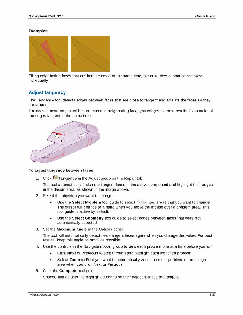
SpaceClaim 2009+SP1 User’s Guide
www.spaceclaim.com 340
Examples
Filling neighboring faces that are both selected at the same time, because they cannot be removed individually
Adjust tangency
The Tangency tool detects edges between faces that are close to tangent and adj usts the faces so they are tangent.
If a faces is near tangent with more than one neighboring face, you will get the best results if you make all
the edges tangent at the same time.
To adjust tangency between faces
1. Click Tangency in the Adjust group on the Repair tab.
The tool automatically finds near-tangent faces in the active component and highlight their edges
in the design area, as shown in the image above.
2. Select the object(s) you want to change:
Use the Select Problem tool guide to select highlighted areas that you want to change.
The cursor will change to a hand when you move the mouse over a problem area. This tool guide is active by default.
Use the Select Geometry tool guide to select edges between faces that were not automatically detected.
3. Set the Maximum angle in the Options panel.
The tool will automatically detect near-tangent faces again when you change this value. For best results, keep this angle as small as possible.
4. Use the controls in the Navigate ribbon group to view each problem one at a time before you fix it.
Click Next or Previous to step through and highlight each identified problem.
Select Zoom to Fit i f you want to automatically zoom in on the problem in the design
area when you click Next or Previous.
5. Click the Complete tool guide.
SpaceClaim adjusts the highlighted edges so their adjacent faces are tangent.

SpaceClaim 2009+SP1 User’s Guide
www.spaceclaim.com 341
Tool guides
The following tool guides help step you through the process:
The Select Problem tool guide is active by default. This tool guide allows you to select problem areas that are automatically found by the tool.
The Select Geometry tool guide allows you to select edges between faces that were not automatically found. Hold Ctrl to select multiple edges or box select in the design area. When
you hover over an edge, you can see the two faces that would be affected by the change.
The Complete tool guide makes all highlighted edges tangent.
Options
The following options are available in the Options panel:
Maximum
angle
The maximum angle to detect for tangency. For best results, keep this angle as small
as possible.

SpaceClaim 2009+SP1 User’s Guide
www.spaceclaim.com 342
Preparing designs for analysis Use the tools in the Define group to create or subdivide bodies for analysis.
Use the Volume Extract tool to create a solid based on an enclosed region within a part.
Use the Midsurface tool to create a surface midway between two offset faces.
Use the Split by Plane tool to split a part based on a plane.
Use the Spot Weld tool to define points on two faces that represent weld points.
Use the Imprint tool to imprint coincident faces.
Tools in the Remove group help you easily remove elements to simplify your designs.
Use the Rounds tool to remove rounded edges from a design.
Use the Faces tool to remove features from a design.
Use the Interference tool to merge parts that clash.
Create and edit beam objects with the tools in the Beams group.
Use the Profiles tool to select a profile for a beam object.
Use the Create tool to define a beam using a profile from the library.
Use the Extract tool to define a beam and profile from a solid.
Use the Orient tool to change the orientation or axis of the beam.
Use the Display tool to change how beams are displayed.
Extracting volume
The Volume Extract tool creates a solid based on the volume enclosed by a single body or set of bodies. A solid named Volume is created in the structure tree, and the bodies used to generate the volume are temporarily transparent when the volume is created.
If a surface intersects any of the edges you select to enclose the region, it will be used to cap the created volume. You can create cleaner caps by placing surfaces at each of the edges you use to define the enclosed region.
If an edge will be removed when you use the Volume Extract tool, that edge will flash red and you will receive a warning message. This can happen when you select a capping edge that will be removed when it is merged with the rest of the model. The highlight identi fies the problem so you
can pick a different edge.
To create a volume body
1. Click Volume Extract in the Define group on the Prepare tab.
2. Select the edge loops that enclose the volume of the area. Double -click to select more than one contiguous edge.
3. If necessary, click the Select Seed Face tool guide and select a face inside the volume area.
You can select a split face as the seed face.

SpaceClaim 2009+SP1 User’s Guide
www.spaceclaim.com 343
You only need to use this tool guide if the Volume Extract tool fails to correctly identify the inside of the volume.
4. Click the Complete tool guide.
SpaceClaim creates a surface part based on the volume you defined.
To update the volume body
Right -click the volume part (named Volume by default) in the Structure tree. Select one of the following
commands:
Regenerate Volume Body as Created updates the volume body based on objects that were visible when the volume was created (regardless of their current visibility). Use this option for simple
regeneration or to add interfering bodies to the volume calculation.
Regenerate Volume Body in Context updates the volume body based on objects that are currently visible in the design area. Use this option to remove bodies from the volume calculation.
Tool guides
The following tool guides help step you through the process:
The Select tool guide is active by default. Use this tool guide to select loops of edges that enclose the volume area.
The Select Seed Face tool guide allows you to select a face that will help determine the inside of the enclosed volume.
The Complete tool guide creates the volume solid based on the edges and seed face you select.
Creating midsurface faces
This tool creates a surface midway between two offset faces. The midsurface faces are automatically
extended or trimmed to adjacent faces, and the distance between the faces is stored as a thickness property. You can use these surfaces for FE analysis.
Color highlighting shows you face pairs that have been selected, as shown below. The midsurface face
will be offset from the cyan faces. Green indicates that a face is paired with a cyan face. Unselected faces and faces without offsets are shown in the original color.
The thickness of the original model face offsets are stored as a property named Thickness in the
Midsurface section of the Properties panel. This is a face property, so you must select the face in the Design window rather than in the Structure tree, even if it is a single face. You can change this property, and it is included in the ANSYS data when it is sent out to ANSYS via the SpaceClaim add-in.

SpaceClaim 2009+SP1 User’s Guide
www.spaceclaim.com 344
The Midsurface tool detects and removes small faces of midsurfaces that are created when an edge is equal to half of the part thickness.
If the Midsurface tool finds missing faces because neither side can be offset, you will receive an error message in the error box that lists the faces. If the tool fails to create midsurface parts, the problem faces or edges are highlighted.
Midsurfaces inherit the material properties of their parent components, but you can change the material properties for the midsurface object.
To create midsurface faces by selecting offset pairs
1. Click Midsurface in the Define group on the Prepare tab.
2. Select the Use selected faces option in the Options panel.
This option automatically detects all offset face pairs on a body with one or more offset distances.
3. Click on a face for which you want to create a midsurface.
4. Click on a second face that makes an offset pair with the first face. All face pairs that have the same offset distance will be added to the selection.
5. Click detected face pairs to remove them or click undetected face pairs to add them.
Two faces may be detected as a pair because they have the same offset distance as the face pairs to be midsurfaced. Click on the blue face to remove the pair from selection.
A face pair that should be midsurfaced may not be detected because its offset pair is not a perfect offset of the first face. Click on the face you want offset to add it to the selection. Its midsurface will be offset using the thickness of neighboring detec ted face pairs.
6. (Optional) Click the Select Faces tool guide or hold the Ctrl key and select additional face pairs with a different offset distance.
When you add face pairs, all face pairs with the same offset distance will be added to the
selection.
7. Click the Complete tool guide when you are finished selecting faces.
When you successfully create a midsurface, the solid will become semi-transparent and the
surface will be opaque until you select a different tool or clear your selection.
Midsurface bodies are created in a component in the Structure tree, and are named using the name of the original object and appended with MidsurfaceN, where N is a unique number.
To create midsurface faces based on an offset range
1. Click Midsurface in the Define group on the Prepare tab.
2. Select Use range in the Options panel.
The face pairs with offset distances within the range are automatically detected. If you have face pairs selected, the range will automatically change to include the offset distance.
3. Click the body for which you want to detect offset face pairs.
4. Change the Minimum thickness and Maximum thickness values in the Options panel as needed.
Face pairs within this range will be selected; face pairs outside this range will be removed from the selection.
5. Click the Complete tool guide when you are finished selecting faces.

SpaceClaim 2009+SP1 User’s Guide
www.spaceclaim.com 345
To add or remove faces from selection
To add or remove a detected face pair, click either face in the pair.
The midsurface distance will be offset from this face the same distance as adjacent faces, regardless of any potential offset pair for this face.
If the face has an offset pair that was previously selected, the pair will be deselected.
You may need to remove a face from selection if it is paired incorrectly.
To change the thickness of a midsurface face
1. Select the midsurface face in the Design window.
2. Change the Thickness property in the Properties panel.
To make a midsurface body from a regular open surface body
1. Select the surface in the Structure tree.
2. Change the Thickness property in the Properties panel.
Tool guides
The following tool guides help step you through the process:
The Select Faces tool guide is active by default. This tool guide allows you to select a pair of
offset faces, and all other face pairs with the same offset distance are automatically detected.
The Add/Remove Faces tool guide allows you to select additional faces to offset or remove
detected face pairs from the selection.
The Swap Sides tool guide allows you to switch the face pairs. You may need to do this
when you detect pairs with more than one offset distance, and the offset relationships are incorrectly detected.
The Complete tool guide creates the midsurface faces.
Options
The following options are available in the Options panel:
Use selected faces Select this option to create midsurfaces for only the faces you select.
Use range Select this option to create midsurfaces on all faces in the specified thickness range.
Thickness tolerance Change the value of this option to detect offset spline faces with an offset value within the tolerance amount.
Create midsurfaces in
Select Same component to create the midsurfaces in the same component as the part you midsurface. Select Active component to create the midsurfaces in the active component.
Group midsurfaces Select this option to create midsurfaces in a new sub-component. Deselect the option to create the midsurface objects in the component you select in the option above (same component or active component).

SpaceClaim 2009+SP1 User’s Guide
www.spaceclaim.com 346
Examples
Selecting an additional face pair with the Use selected faces option and the Select Faces tool guide. All face pairs with the same offset are added to the selection.
Removing a face that was automatically detected but not desired as a midsurface pair
The structure created for midsurface parts
Defining weld points
The Spot Weld tool creates points on two faces that represent weld points. Each spot weld consists of
two points: one on each face that is to be welded together. Each point must lie on a face or edge. For export to ANSYS, each point must lie on a different solid or surface part.
When spot weld points are found on another body, the set does not include points with mates within the
same body, as shown below. Weld points in a set that have mates are blue and points that do not have mates are gray

SpaceClaim 2009+SP1 User’s Guide
www.spaceclaim.com 347
Spot welds are updated with changes to the guiding edges or base faces.
If a guiding edge disappears, the points created along it are removed.
If a mate face moves out of the search range the weld point, the pairs to that mate face will disappear.
If the mate face moves back into the range, the point pairs will reappear.
If pairs cannot be found for all of the points on the base face, the spot weld is marked in the Structure tree with an error icon showing that it is no longer valid.
Dimensions for spot weld point patterns are displayed in the Design window. These dimensions look the same as dimensions for other patterns.
Exporting to ANSYS
Spot welds defined for the design can be exported to ANSYS. ANSYS Design Modeler and ANSYS
Workbench recognize the weld points with the following limitations:
Only points with mates can be used for simulation.
You may place weld points between multi-body parts if the two bodies belong to different parts. Spot welds defined between bodies in the same part are not transferred to simulation.
You can approximate seam welds by placing weld points on the guiding edge with an offset of zero, if no mating face is found on either side of the base face.
SpaceClaim supports spot welds of more than two weld points (more than two components are welded together at one location), but Simulation does not; Simulation ignores any weld points after
the first two supplied.
If a spot weld joint in SpaceClaim contains a spot weld with more than two weld points, then a chain of pairs of weld points is transferred to Simulation as separate spot welds, and each two-point spot
weld is listed separately under the Connections node. For example, if a single SpaceClaim spot weld connects parts A-B-C-D, this is transferred as three separate spots welds: A-B, B-C, and C-D.
To define weld points
1. Click Spot Weld in the Define group on the Prepare tab.
2. Select base face.
This is the face or faces on which the weld points will be defined. You should select a single face or a chain of tangent faces.
3. Click the Select guiding edges tool guide and select an edge.
This is the edge along which the weld points will be defined. The tool searches for mating edges in the following directions:
a. The surface normal.
b. The opposite direction of the surface normal.
c. If no match is found for a or b, then the direction perpendicular to both the surface normal and edge tangent is searched.
You can hold Ctrl and double-click to select a chain of edges.
4. (Optional) If you want to define a different mating face, click the Select mating faces tool guide and select a mating face.
You can select more than one face. Clicking on a mating face removes all previously selected faces and holding Ctrl adds a face.
5. Set the following options:
Start offset: The distance of weld points from the beginning of the guiding edge.
Edge offse t: The distance of weld points from the guiding edge.

SpaceClaim 2009+SP1 User’s Guide
www.spaceclaim.com 348
End offset: The distance of weld points from the end of the guiding edge.
Number of points: The number of weld points to define for each edge chain.
Increment: The distance between weld points.
You can set either the number of points or the increment. The last value you enter will be used. For example, i f you change the number of points, the increment will automatically update. If you then change the increment, the number of points will change.
Search range: The distance to search for mating faces from the guiding edge.
Click the Create spot weld tool guide to define the spot welds.
To redetect mating faces
1. Right -click a face with spot welds.
2. Select Redetect Mating Faces.
Spot welds will be placed on any new nearby faces.
Tool guides
The following tool guides help step you through the process:
Use the Select Base Faces tool guide to select the face or faces on which the weld points will be defined. You should select a single face or a chain of tangent faces.
Use the Select Guiding Edges tool guide to define the edge along which the weld points will be defined.
Use the Select Mating Faces tool guide to change the mating face from the face that is automatically detected. You can select more than one face. Clicking on a mating face removes all previously selected faces and holding Ctrl adds a face.
The Complete tool guide completes the spot weld definition.
Options
The following options are available in the Options panel:
Start offset The distance of weld points from the beginning of the guiding edge.
Edge offse t The distance of weld points from the guiding edge.
End offset The distance of weld points from the end of the guiding edge.
Number of points
The number of weld points to define for each edge chain.
Increment The distance between weld points. You can set either the number of points or the
increment. The last value you enter will be used. For example, if you change the number of points, the increment will automatically update. If you then change the increment, the number of points will change.
Search range The distance to search for mating faces from the guiding edge.

SpaceClaim 2009+SP1 User’s Guide
www.spaceclaim.com 349
Examples
Spot welds that cross over multiple nearby welded parts
Creating enclosures
An enclosure is a solid around a body or bodies that has a cushion around the enclosed solid(s). The
enclosure can be a box, cylinder, or sphere, as shown below.
Enclosures are used by analysis tools to simulate fluid.
To create an enclosure
1. Click Enclosure in the Define section on the Prepare tab.
2. Select a solid or solids in the Design window or Structure tree.
These solids will be inside the enclosure.
3. Set the Default cushion amount.
This is a percentage of the minimum enclosure size, and determines the initial distance between the enclosed object(s) and the closest point of the enclosure to the objects. You can adjust the
distances by typing in the fields in the Design window.
4. Select the shape of the enclosure in the Options panel: Box, Cylinder, Sphere, or Custom shape.
If you select Custom shape, you must use the Custom Shape tool guide to select a solid to use as the enclosure shape.
5. (Optional) Click the Set Orientation tool guide and select a line, axis, or origin to change the
orientation of the enclosure.

SpaceClaim 2009+SP1 User’s Guide
www.spaceclaim.com 350
The enclosure is oriented with the world origin by default.
6. (Optional) Deselect the Symmetric dimensions option to set the cushion distance different for
dimsions that are opposite each other.
7. (Optional) Type a value to adjust the cushion values, if necessary.
Press Tab to move among the cushion values.
8. Click the Complete tool guide when you are finished.
The enclosure is created in a subcomponent of the active part.
Tool guides
The following tool guides help step you through the process:
Use the Select Bodies tool guide to select the bodies that will be enclosed.
Use the Set Orientation tool guide to change the orientation of the enclosure relative to your design or the axis of a coordinate system.
Use the Custom Shape tool guide to select a solid to use as the custom shape when you set the enclosure type to Custom in the Options panel.
Click the Complete tool guide when you are finished.
Options
The following options are available in the Options panel:
Default cushion
This is a percentage of the minimum enclosure size, and determines the distance between the enclosed object(s) and the closest point of the enclosure to the objects.
You can change adjust the distances by typing in the fields in the Design window.
Enclosure type
Select an enclosure shape from the list. If you select Custom shape, you must use the Custom Shape tool guide to select a solid to use as the enclosure shape.
Symmetric dimsions
Forces the dimensions to remain symmetric. Deselect this option if you want to enter values for dimensions and you don't want the opposite dimensions changed.
Examples
Changing the cushion by typing in the field doesn't change the size of the opposite cushion. The
Symmetric dimensions option must be disabled.

SpaceClaim 2009+SP1 User’s Guide
www.spaceclaim.com 351
Changing the orientation of the enclosure so it is aligned with the edge highlighted in yellow aligns the enclosure with that edge.
Splitting by plane
The Split by Plane tool splits parts based on a plane. It is intended to be used to split symmetrical parts for analysis. This tool is similar to Split Solid, except Split by Plane allows you to select an axis, point, or
edge, to use as splitting plane locations which are not allowed by Split Solid.
The part below has been split along the length of its handle. The purple and green parts are symmetrical, and can be analyzed faster than the whole part.
To split by plane
1. Click Split by Plane in the Define group on the Prepare tab.
2. Select the object(s) you want to split.
3. Select a plane to split the object:
To split the part on the same plane as a face, edge, or point, click Select Cutter and select a reference face, edge, or point.
To define a temporary plane based on design elements, click Build Cutting Plane and select faces, edges, or points to define the plane. You can select more than one face, edge, or point, and the cutting plane will be created that bisects the elements. The
wrench in the image above is tapered. Using the Build Cutting Plane tool guide, you can select the top and bottom of the wrench to create a plane that bisects the wrench along its plane of symmetry.
4. To delete objects created by the split, click the Select Regions tool guide and mouse over the parts created by the split. The regions will be highlighted. Click to delete the region.
5. Click the Complete tool guide.
SpaceClaim splits the solid along the plane.
Tool guides
The following tool guides help step you through the editing process:
The Select Target tool guide is active by default. Use this tool guide to select the object that
will be split.

SpaceClaim 2009+SP1 User’s Guide
www.spaceclaim.com 352
Use the Select Cutter tool guide to select a reference face, edge, or point with which to cut the part. Use Ctrl to select more than one object. The plane is previewed in gray before you
select the reference object.
Use the Build Cutting Plane too guide to select faces, edges, or points to create a temporary plane with which to cut the object. The temporary plane(s) are shown with a
dashed line. Select a temporary plane to complete the split.
Use the Select Regions tool guide to select regions that will be removed. You can move your mouse over regions that were created and highlight them before you click to delete.
Options
The following options are available in the Options panel:
Merge when
done
Select this option to merge all touching solids or surfaces when you exit the tool. Hidden
objects are not merged. This saves you the extra step of selecting all the cut -up regions after you are done and manually merging them all back together.
Extend adjacent faces
Use this tool to extend or trim surfaces and merge them with nearby parts, or to extend or trim sketch curves. The tool automatically detects faces that can be extended or trimmed and highlights them, as
shown below. Click on a highlighted area to perform the extension or trimming. You can also select a surface that wasn't automatically detected and attempt to extend or trim it. This tool only works with surface parts and sketch curves.
To extend or trim adjacent surfaces
1. Click Extend in the Define group on the Prepare tab.
The edges of surface parts or sketch curves that can be extended or trimmed are highlighted.
Chains of tangent faces are automatically grouped to offset them together.
2. Change the following options:
Maximum distance: The maximum distance between surfaces. The tool will search for
adjacent faces again if you change this value.
Trim surfaces: Controls whether or not surfaces may be trimmed in addition to extended.
Partial intersections: Controls whether or not faces that partially intersect are detected.
Same body: Allows a surface to be trimmed or extended by a face or edge on the same
body.
Merge after extend or trim: Merges bodies, if possible, when you trim or extend an edge on one surface body up to a face or edge on another body.

SpaceClaim 2009+SP1 User’s Guide
www.spaceclaim.com 353
3. If you want to extend or trim only some of the surfaces or sketch curves, click the highlighted spots.
Hold Ctrl to select multiple edges.
The surfaces or sketch curves are extended or trimmed when you click on them.
4. Click Complete if you want to extend or trim all highlighted surfaces.
Press Esc to cancel the operation.
Tool guides
The following tool guides help step you through the process:
The Select Problem tool guide is active by default. This tool guide allows you to select and
fix problem areas that are automatically found by the tool.
The Select Geometry tool guide allows you to select faces that were not automatically
found. Hold Ctrl to select multiple objects or box select in the design area.
The Complete tool guide merges or trims the highlighted surfaces.
Options
The following options are available in the Options panel:
Maximum distance
The maximum distance between parts. The tool will search for adjacent faces again if you change this value.
Trim surfaces Controls whether or not surfaces may be trimmed in addition to extended.
Partial intersections
Controls whether or not faces that partially intersect are detected.
Same body Allows a surface to be trimmed or extended by a face or edge on the same body.
Merge after extend or trim
Merges bodies, if possible, when you trim or extend an edge on one surface body up to a face or edge on another body.
Examples
Curves are extended from endpoint to endpoint.
The edges of separate surfaces are merged when you select the Merge after extend or trim option.

SpaceClaim 2009+SP1 User’s Guide
www.spaceclaim.com 354
Imprinting
The Imprint tool detects coincident edges (edges from one body that lies in the face of another body) and
imprints them onto the coincident face. The contact regions will be the same shape, and the resulting mesh on each face will be similar. This can be helpful when analyzing st ress between two parts.
To imprint a part
1. Click Imprint in the Define group of the Prepare tab. The tool will automatically detect and
highlight coincident edges, as shown in the image above.
2. Select the object(s) you want to change:
Use the Select Problem tool guide to select highlighted areas that you want to change.
The cursor will change to a hand when you move the mouse over a problem area. This tool guide is active by default.
Use the Select Geometry tool guide to select edges that were not automatically detected. You can use box, lasso, and paint select modes.
3. Use the controls in the Navigate ribbon group to view each problem one at a time before you fix it.
Click Next or Previous to step through and highlight each identified problem.
Select Zoom to Fit i f you want to automatically zoom in on the problem in the design
area when you click Next or Previous.
4. Click the Complete tool guide.
SpaceClaim imprints the selected edges of the coincident faces.
Tool guides
The following tool guides help step you through the editing process:
The Select Problem tool guide is active by default. This tool guide allows you to select problem areas that are automatically found by the tool.
The Complete tool guide imprints all the highlighted edges.

SpaceClaim 2009+SP1 User’s Guide
www.spaceclaim.com 355
Remove rounds
The Rounds tool provides a quick and easy way to remove rounds from an object. It is like the Fill tool,
except you can only select rounded edges.
You will have a greater chance of success if you select only a few rounds at a time to remove. If you spend a lot of time removing rounds, you may want to check out SpaceClaim's tutorials or technical
support for advanced techniques you can use when removing rounds.
You may need to split and partially remove one or more rounds before adjacent rounds can be removed, especially when two or more rounded faces meet along an edge or vertex. The rounded face is split and
filled in the middle.
To remove rounds
1. Click Rounds in the Remove group on the Prepare tab.
2. To split and partially remove a round:
a. Hover over one tangent edge of the rounded face to preview the splits.
b. If necessary, change the Cap width option to adjust the percentage of the round face that is removed.
c. Click on the edge to split the rounded face.
3. Select the rounds you want to remove:
a. Click an object in the Structure tree to select all rounds on the object.
b. Select a round face in the design area. You can hold Ctrl and select faces or draw a box to
select multiple faces.
c. Ctrl+click to deselect a face.
4. Select Auto-shrink fill area in the Options panel to split faces near the ends of round chains. Use this option to simplify the procedure so it can be successful.
5. Click the Complete tool guide.
SpaceClaim will remove the rounded faces you selected and replace them with a sharp edge.
Tool guides
The following tool guides help step you through the process:
The Select Rounds to Remove tool guide is active by default. You can also select by drawing a box in the design window. You can only select round faces while this tool is active.
The Complete tool guide finishes the operation.
Options
The following options are available in the Options panel:
Auto-shrink fill area
Select this option to split faces near the ends of round chains. Use this option to simplify the procedure so it can be successful.
Cap width The percentage of the width of a round that is removed when you click on an edge of an existing round. The splits are previewed as the cursor is moved along the round tangent edges.

SpaceClaim 2009+SP1 User’s Guide
www.spaceclaim.com 356
Examples
Splitting and partially removing a round
Remove faces
The Faces tool allows you to quickly remove faces from your design. Use it to simplify your design by
removing holes, protrusions, etc.
To remove faces from an object
1. Click Faces in the Remove group on the Prepare tab.
2. Select the faces you want to remove. Hold the Ctrl key to select more than one face.
3. Click the Complete tool guide.
SpaceClaim attempts to remove the selected faces by extending neighboring faces.
Tool guides
The following tool guides help step you through the process:
The Select Faces to Remove tool guide is active by default. You can also select by drawing a box in the design window. You can only select faces while this tool is active. Edges and
vertices will not be selected.
The Complete tool guide finishes the operation.
Remove interference
The Interference tool detects and removes interference from clashing bodies. The interference is removed from the body with the most faces.
The tool searches all visible bodies for interference. Bodies that are hidden (turned off in the Structure tree) are ignored.
If you want to remove an interfering region from one of the bodies, use the Interference Volumes tool on
the Measure tab to create a solid of the interfering region. You can then use the Combine tool to remove this solid from one of the parts.

SpaceClaim 2009+SP1 User’s Guide
www.spaceclaim.com 357
To remove interference
1. Click Interference in the Remove group on the Prepare tab.
The tool will automatically detect and highlight interference, as shown in the image above.
2. Select the object(s) you want to change:
Use the Select Problem tool guide to select highlighted areas that you want to change. The cursor will change to a hand when you move the mouse over a problem area. This
tool guide is active by default.
Use the Select Geometry tool guide to select edges that were not automatically detected.
3. Click the Complete tool guide.
SpaceClaim removes the interference by merging the bodies into one part.
Tool guides
The following tool guides help step you through the process:
The Select Problem tool guide is active by default. This tool guide allows you to select
problem areas that are automatically found by the tool.
The Select Geometry tool guide allows you to select edges that were not automatically
found. Hold Ctrl to select multiple edges or box select in the design area.
The Complete tool guide merges the clashing objects.
Beams
A beam is a long, thin object with a constant cross-section. Defining objects as beams, rather than modeling them as solid geometry, simplifies the model and analysis.
To create a beam
1. Create objects to define the beam path
One or more of these methods can be used in the same design.
Sketch curves: Use any of SpaceClaim's sketching tools to create straight or curved segments and then assign beam profiles to them. These sketch curve beams can then be
modified just like any curve in SpaceClaim using the Move, Pull, Select, Scale, Bend, Extend, and Trim tools. This method is a straightforward, lightweight way to create beam structures.
Edges of a solid or surface : Use this method when you have solid geometry that you want
to reference for the beams. For example, to create a simple rectangular cage of beams, sketch a rectangle, pull it into a solid, and assign beams to all of the edges. If you change the solid, then the beams will dynamically update to match the location and length of the edges.
Any of SpaceClaim's modeling tools can be used to create sophisticated geometry changes that drive changes to the beam structure.
For example, beams are assigned to the edges of the rectangular part shown below, and
then the edges are bent. The beams are automatically updated when the solid is changed.

SpaceClaim 2009+SP1 User’s Guide
www.spaceclaim.com 358
Two points or midpoints in a model: You can use any two points in a model to define a straight beam segment. Planes can be used to create "stages" or additional locations for
defining beams to or from. A beam can be created to the intersection point of any plane with any edge. When a defining plane is moved, any associated beams dynamically update their locations. You can create sophisticated tower and truss struc tures using this method, and the
structures will be easily adaptable to unforeseen design changes.
In the example below, one end of each diagonal beam was created at the intersection of the plane and the solid. The beams change when the plane is moved.
2. Add a profile to your structure
a. Click Profiles in the Beams group on the Prepare tab.
b. Select a profile from the library or click More Profiles to load a profile that is saved as an SCDOC file.
See Changing beam profiles.
More than one beam can reference the same profile, so the characteristics of all beams that use that profile will change if you edit the profile.
Create the beam path
. Click Create in the Beams group on the Prepare tab.
The Create tool won't be active until you select a profile, which adds the profile to your design document.
a. Select edges or points to define the path:
Click the Select Point Chain tool guide and then select an edge or curve, or click on a series of points to create the path.
Click the Select Point Pairs tool guide and then select a beginning and end point for the path.
You can use intersection points and midpoints on edges and other beams. Click on the small triangles on the ends and midpoint when you hover over an edge or beam.
See Creating a beam.
A Beams folder is created for the beams and a Beam Profiles folder is created for the profiles in the Structure tree:

SpaceClaim 2009+SP1 User’s Guide
www.spaceclaim.com 359
The profile name is displayed in parenthesis after the beam name in the Structure tree.
Extracting beams from solids
If you have already modeled the beam you can convert it to a beam object. See Extracting a beam from a
solid.
Beams and ANSYS
If you send a design with beams to ANSYS, the following is sent for each beam object:
Profile and path
Beam properties
Profile properties
Material properties
Beams and shared topology
Beams can share topology with surfaces when
The end point of the beam lies on the surface:
The path of the beam lies in the surface.
The beam intersects a surface at a point.
The beams and surfaces must be in the same component, the component must be set to share, and the
mixed import option in Workbench must be set to lines and surfaces. See Shared topology in ANSYS for more information about shared topology.
Beam highlighting
The following table shows how beams, sketch lines, and edges look when they are highlighted and selected:
Highlighted Selected Selected and highlighted
Beam

SpaceClaim 2009+SP1 User’s Guide
www.spaceclaim.com 360
Sketch
Edge
Creating a beam
The library of standard profiles includes several basic beam profiles. You can use these profiles and edit them to your own dimensions.
Create a beam
1. Click Create in the Beams group on the Prepare tab.
The Create tool won't be active until you select a profile, which adds the profile to your design document.
2. Select edges or points to define the beam path:
Click the Select Point Chain tool guide and then select an edge or curve, or click on a series of points to create the path.
Click the Select Point Pairs tool guide and then select a beginning and end point for the path.
You can use intersection points and midpoints on edges and other beams. Click on the small triangles on the ends and midpoint when you hover over an edge or beam.
The beam object is defined, and the Beams and Beam Profiles folders are created in the Structure tree. The profile name is displayed in parenthesis after the beam name in the Structure tree.
Tool guides
The following tool guides help step you through the process:
Use the Select Point Chain tool guide to create a beam along an edge or a series of points that you select.
Use the Select Point Pairs tool guide to create a beam between two points.
Extracting a beam from a solid
Use this method to convert an existing 3D solid into a beam.

SpaceClaim 2009+SP1 User’s Guide
www.spaceclaim.com 361
To extract a beam from a solid
1. Click Extract in the Beams group on the Prepare tab.
2. Select a solid in the Design window.
The beam object is defined, and the Beams and Beam Profiles folders are created in the Structure tree.
If you select faces on multiple bodies, then beams will be extracted for each body.
Similar profiles are detected when you extract beams from 3D geometry. The resulting beams are linked to the same profile, so multiple profiles with the same shape are not created.
Beam properties
Select a beam in the Beams folder and you can change the following properties, which are found in the Beam section of the Properties panel:
Profile Name
Orientation: The angle of the profile relative to the path.
Reversed: Changing this property flips the profile.
Section Anchor: Select the location where the profile intersects with the path of the beam: Area Centroid, Shear Center, or Location. If you select Location, then you can enter the X and Y
coordinates of the anchor location. Area Centroid is the default.
Location: Correspond with the orientation arrows in the beam Orient tool.
To rename a beam in the Structure tree, right-click and select Rename.
Beams can also have material properties just like other objects.
See Changing beam profiles for information about beam profile properties.
Formulas used for Beam Section properties
The following beam cross-section properties are calculated by SpaceClaim and transferred to ANSYS.
The area of section:
The X coordinate of the centroid:
The Y coordinate of the centroid:
Moment of inertia about the X axis:
Moment of inertia about the Y axis:
Product of inertia:
The warping constant, shear center and torsional constants are calculated from the warping function, ϕt. The warping function is the solution to the St. Venant boundary value problem for pure torsion:

SpaceClaim 2009+SP1 User’s Guide
www.spaceclaim.com 362
Using the Trefftz definition, the shear center and warping constant are calculated purely as a property of the section:
X coordinate of shear center:
Y coordinate of shear center:
Warping constant:
with
Changing beam profiles
Profiles are found in the Beam Profiles folder in the Structure tree.
To change the profile for a beam
1. Select the beam in the Structure tree or Design window.
2. Click Profiles in the Beams group on the Prepare tab.
3. Select a profile from the list or the library.
The name of the beam in the Beams folder changes to the name of the profile, and the
new profile is added to your Beam Profiles folder.
To view beam profile properties
Select a beam profile in the Beam Profiles folder in the Structure tree.
The profile properties are displayed in the Properties panel. These properties are read-only and cannot be changed.
See Beam properties.
To edit a profile
1. Right -click the profile on the Structure tree.
2. Select Edit Beam Profile.
The profile will open as a sketch in a new Design window.
3. Change the profile like you would a sketch.

SpaceClaim 2009+SP1 User’s Guide
www.spaceclaim.com 363
Each profile has driving dimensions set up in the Groups panel, and each annotation dimension is labeled to show you which group it corresponds with. You can change these dimensions to alter
the profile. See Working with groups.
To set the default profile
1. Clear your selection by clicking in empty space in the Design window.
2. Click Profiles in the Beams group on the Prepare tab.
3. Select a profile from the list or from the profile library.
New beams you create during this session will use this profile by default.
The default profile is not persistent and will be cleared when you restart SpaceClaim.
To remove a profile from the Beam Profiles folder
1. Select the profile in the Structure tree.
2. Click Profiles in the Beams group on the Prepare tab.
3. Click Remove Profile.
Examples
The labels of the annotation dimensions on a beam profile correspond with the group names.
Changing beam orientation
Use this tool to change the direction of a beam, rotate it around its anchor point, and offset it from its
anchor point.

SpaceClaim 2009+SP1 User’s Guide
www.spaceclaim.com 364
To change a beam's orientation
1. Click Orient in the Beams group on the Prepare tab.
2. Select a beam in the Structure tree or Design window.
You can click Display in the Beams group and change the display mode to Solid Beams while the Orient tool is active. You may want to do this so you can see the beam.
3. (Optional) Click the Orient to Object tool guide or hold the Alt key and select a reference object,
and the beam will be oriented to the projected Z direction of the plane of the selected object.
4. Use the blue arrows to change the beam's orientation:
Click the straight blue arrow (X axis) to reverse the beam's direction.
Drag the curved blue arrow to rotate the beam around its anchor point.
Double-click the curved blue arrow to rotate the beam 90°.
Drag the red or green arrows (Y and Z axes) to offset the beam.
Tool guides
The following tool guides help step you through the process:
The Select tool guide is active by default. This tool guide allows you to select the beam object that you want to reorient.
The Orient to Object tool guide allows you to select a face, edge, or axis and orient the beam in that direction.

SpaceClaim 2009+SP1 User’s Guide
www.spaceclaim.com 365
Examples
Offsetting a beam along the Y axis.
Moving beams
You can use the Move tool to move beams. The Move tool has a special Keep beam fixed option for
beams. This options causes the beam (shown in dark green) to be offset while the profile (shown as a green semi-t ransparent 3D object) remains fixed.
When you move more than one beam at a time and select the Keep beam fixed option, the beam
profiles moving along a trajectory that can be reversed (normal to the trajectory) are moved and the beam profiles that can't be reversed (along the trajectory) remain fixed. The beam is offset with equal and opposite changes to the Location property and the location of the beam's section is maintained. You can
see this in the preview geometry for the beam.
Moving the beams without the Keep beam fixed option moves all beams and profiles:
Moving the beams with the option selected moves the two beams that are normal to the trajectory, but the
two beams that aren't normal to the trajectory are offset:

SpaceClaim 2009+SP1 User’s Guide
www.spaceclaim.com 366
Changing beam display style
You can display the beam as a wireframe or as a lightweight model.
To change the beam display
1. Click Display in the Beams group on the Prepare tab.
2. Select a display type:
Wire Beams displays the beam as a wire or a thin line in the Design window.
Solid Beams displays the beam as a lightweight solid, so it is displayed as a semi-transparent 3D object.
Creating a new beam profile
You can create your own beam profiles and save them as files.
To use these profiles, click Profiles, select More Profiles, and then browse to locate the SCDOC file.
To create a profile without creating a beam
1. Sketch the profile.
2. Click Pull in the Edit group on the Design tab.
3. Pull to extrude the profile into a solid.
4. Change the color of the face you want to use as the profile.
You can change this face to any color, as long as it overrides the color of the solid. Only one face can have a color override, otherwise SpaceClaim won't know which face is used for the profile.
5. Insert an origin at the location where the profile should intersect with the path of the beam.
6. Save the design as an SCDOC file.
To create a profile based on an extracted beam
1. Sketch the profile.
2. Click Pull in the Edit group on the Design tab.
3. Pull to extrude the profile into a solid.
4. Click Extract in the Beams group on the Prepare tab.
5. Select the solid you created in the previous steps.
6. Right -click the profile in the Beam Profiles folder and select Save beam profile.
7. Browse to the folder where you want to save the profile, type a file name, and click Save.

SpaceClaim 2009+SP1 User’s Guide
www.spaceclaim.com 367
Creating, opening, and saving documents When you create a new design, it appears on a tab in the workspace. Designs can contain drawing
sheets, multiple windows, and 3D markups. Each drawing sheet and 3D markup appears on its own tab in the workspace. You can edit your design directly using the drawing sheet.
You can create a drawing sheet for an existing design, or you can begin with an empty drawing sheet
Click a tab at the bottom of the SpaceClaim application window to display that design, drawing sheet, or 3D markup document, or click the arrow icons to cycle between them. Click the x icon to close the tab.
To create a new design
Select New > Design from the Application menu.
To create a new drawing sheet for the active design
Select New > Drawing Sheet from the Application menu to create a drawing sheet with three standard views of the design.
Select New > Empty Drawing Sheet to create a drawing sheet without a format or views.
If these menu options are disabled, create a new design.
To create a new design and associated drawing sheet
Select New > Design and Drawing Sheet from the Application menu to create a new design and an associated drawing sheet.
To open an existing design, drawing sheet, or 3D markup document
Select Open from the Application menu and select the file you want to open. The design and its windows, drawing sheets, and 3D markups open.
You can Ctrl+click or Shift+click to open multiple files at once. Mouse over a recent file to see an image of
the design and the full path to the file.
To open an existing design by dragging and dropping
Drag the .scdoc file icon to anywhere in the title bar and ribbon area.
You can also drag the icon into the design window if no design tab is open.
This will open the design in 3D mode along with all of its drawing sheets, annotations, etc.
To insert a design by dragging and dropping
Drag the .scdoc file icon into the design window.
This will insert the design into the active window in 3D mode. Drawing sheets, annotations, etc. are not
inserted.
To save a design
Select Save from the Application menu.
If you imported or opened non-SpaceClaim designs as multiple external documents, click References to
specify where the documents are saved. Otherwise, opened design documents are stored in their original locations as .scdoc files, and inserted documents are saved in the same directory as your design.

SpaceClaim 2009+SP1 User’s Guide
www.spaceclaim.com 368
To copy a design
1. Save any changes made to external components.
2. Select Save as from the Application menu and enter a new name for the design.
3. Check the Save as copy checkbox if you want to save a copy and continue working in your
original design. Leave this box unchecked to close the original design and display the new design in the Design window.
4. Click Save.
To save a version of your design
Select Save as > New version from the Application menu.
Saving a version allows you to create 3D markups.
To save a design as another file type
Please see Importing and exporting.
To close a design
Make sure its window is active in the workspace, then do one of the following:
Select Close from the Application menu.
Right -click the Design window tab and select Close.
Click the x on the Design window tab bar (at the bottom of the application window).
Click the x at the upper right of the Design window if you have undocked it.
To modify design properties
Document properties are displayed when you select the top-level design in the Structure tree. Right-click in the Properties panel and select Add Property to create a custom property. Expand the property to display its value. Enter a name for the property, select its type (date, Boolean, number, or string), and
enter its value.
Importing and exporting
Use the Open command to open files created with SpaceClaim (.scdoc) or any other modeling application. Use the Save As command to export parts, assemblies, drawing sheets, and 3D markups to formats read by other applications. Your license type determines which of these actions are supported.
If you work frequently with non-SpaceClaim files, we recommend that you set your file options to optimize the importing and exporting process for your needs.
Object IDs for edges, faces, and bodies are now stored within the SCDOC file. Object IDs are preserved
when other files are opened or inserted into SpaceClaim, and the IDs can also be exported. For example, if you export a design to an analysis company, and they tag geometry with load positions, boundary conditions, and so on, then when you re-import that design, make changes, and re-export to the analysis
company, they will not need to recreate their tags on the new design.
If you import a file and it fails, the reason for the failure is reported in the Status Log on the lower right edge of the SpaceClaim window.
File type Open or insert Save as
3D PDF PRC B-Rep
PRC B-Rep or Universal 3D
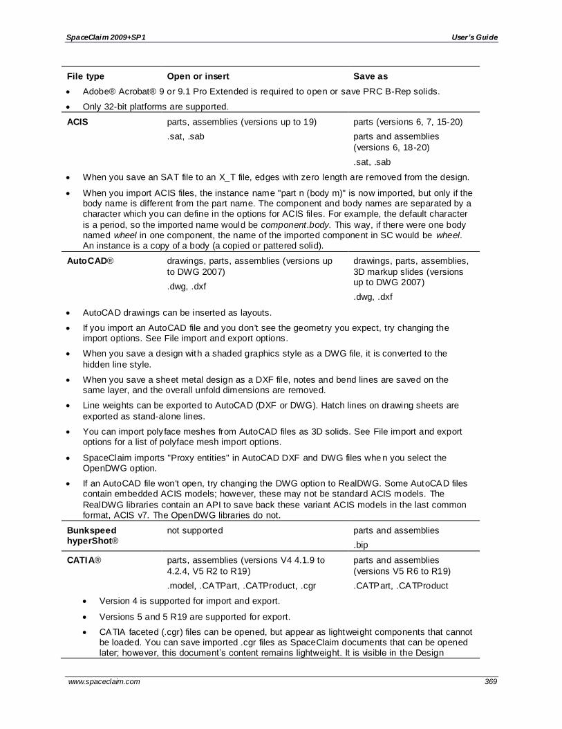
SpaceClaim 2009+SP1 User’s Guide
www.spaceclaim.com 369
File type Open or insert Save as
Adobe® Acrobat® 9 or 9.1 Pro Extended is required to open or save PRC B-Rep solids.
Only 32-bit platforms are supported.
ACIS parts, assemblies (versions up to 19)
.sat, .sab
parts (versions 6, 7, 15-20)
parts and assemblies
(versions 6, 18-20)
.sat, .sab
When you save an SAT file to an X_T file, edges with zero length are removed from the design.
When you import ACIS files, the instance name "part n (body m)" is now imported, but only if the body name is different from the part name. The component and body names are separated by a character which you can define in the options for ACIS files. For example, the default character
is a period, so the imported name would be component.body. This way, if there were one body named wheel in one component, the name of the imported component in SC would be wheel. An instance is a copy of a body (a copied or pattered solid).
AutoCAD® drawings, parts, assemblies (versions up
to DWG 2007)
.dwg, .dxf
drawings, parts, assemblies,
3D markup slides (versions up to DWG 2007)
.dwg, .dxf
AutoCAD drawings can be inserted as layouts.
If you import an AutoCAD file and you don't see the geometry you expect, try changing the import options. See File import and export options.
When you save a design with a shaded graphics style as a DWG file, it is converted to the
hidden line style.
When you save a sheet metal design as a DXF file, notes and bend lines are saved on the same layer, and the overall unfold dimensions are removed.
Line weights can be exported to AutoCAD (DXF or DWG). Hatch lines on drawing sheets are
exported as stand-alone lines.
You can import poly face meshes from AutoCAD files as 3D solids. See File import and export options for a list of polyface mesh import options.
SpaceClaim imports "Proxy entities" in AutoCAD DXF and DWG files whe n you select the OpenDWG option.
If an AutoCAD file won't open, try changing the DWG option to RealDWG. Some AutoCAD files contain embedded ACIS models; however, these may not be standard ACIS models. The
RealDWG libraries contain an API to save back these variant ACIS models in the last common format, ACIS v7. The OpenDWG libraries do not.
Bunkspeed hyperShot®
not supported parts and assemblies
.bip
CATIA® parts, assemblies (versions V4 4.1.9 to
4.2.4, V5 R2 to R19)
.model, .CATPart, .CATProduct, .cgr
parts and assemblies
(versions V5 R6 to R19)
.CATPart, .CATProduct
Version 4 is supported for import and export.
Versions 5 and 5 R19 are supported for export.
CATIA faceted (.cgr) files can be opened, but appear as lightweight components that cannot be loaded. You can save imported .cgr files as SpaceClaim documents that can be opened later; however, this document’s content remains lightweight. It is visible in the Design

SpaceClaim 2009+SP1 User’s Guide
www.spaceclaim.com 370
File type Open or insert Save as window but you can't change the model.
CATIA files with product manufacturing information (PMI) can be opened or inserted.
Visibility is turned off. If a layer doesn't exist, it is created automatically.
ECAD® Board, ECAD® Library
files
.emn, .emp
not supported
Named components are created at the heights and contours defined by the ECAD file. Areas defined as "Keep in" or "Keep out" appear as open sketch lines. When you insert a board file,
SpaceClaim automatically assembles the SpaceClaim document created from the selected file. You can also insert an ECAD library file (EMN) to pre-process it into a library of components for board files.
To import an ECAD file, first open the EMP file to generate a folder of library files in the same directory as the EMP file. Then open the corresponding EMN file to display the ECAD model in SpaceClaim.
If the library folder already exists and it contains files with the same names as those that would be created, the existing files are used. These files may exis t if you previously imported the IDF data, or i f different board layouts share the same components.
The library folder is named <filename> ECAD Library, where <filename> is the name of the IDF file. Each imported file must have its own library. SpaceClaim does not support a shared library for IDF files.
ECAD® IDF files (versions IDF 3.0 and IDF 4.0)
.idf
not supported
Most content within IDF 4.0 files is supported.
Assembly of panels and boards, cutouts, filled areas, keep-ins, materials, panels and everything related, sublayouts, and thermal models are not supported.
IGES parts, assemblies (versions up to 5.3)
.igs, .iges
parts, assemblies (version
5.3)
.igs, .iges
Image files See Inserting an
image
files (insert only)
.bmp, .gif, .jpg, .png, .tif
parts, assemblies, drawing sheets, 3D markup slides
.bmp, .gif, .jpg, .png, .tif
Inventor® parts (versions 6 through 10)
parts and assemblies (versions 11, 12 [2008], 13 [2009])
.ipt
not supported
JT Open parts, assemblies (versions 6.4, 7.0, 8.0, 8.1, 8.2, 9.0)
.jt
parts, assemblies (version 8.0)
.jt
NX parts, assemblies (versions NX1 through
NX6 and UG 11 through 18)
.prt
not supported
Parasolid® parts, assemblies (versions 10.0 through 22)
.x_t, .x_b, .xmt_txt, .xmt_bin
parts, assemblies (versions 12 through 22)
.x_t, .x_b
Point curve text curves (insert only) not supported

SpaceClaim 2009+SP1 User’s Guide
www.spaceclaim.com 371
File type Open or insert Save as
.txt
A spline curve is created by default or i f the option Polyline=False is used. If the option
Polyline=True is used, then the points are connected by straight line segments.
By default, 2D curves are created. When specifying 2D curves, the first column of the data points must be an integer and gives the height of the plane of one of the curves. The beginning of a new curve is specified by changing this height from one line to the next. If option 3D=True
is used, the curves can be 3D
Multiple curves are separated by blank lines.
You can import point curve text files that contain single-point curves, which will be created as points.
Point-curve text files opened or inserted in SpaceClaim display a closed curve when the file has a repeated value.
Curves can be imported to coordinate systems or other geometry like other imported objects.
Point-curve text files with columns separated by commas can be opened or inserted in SpaceClaim. This feature allows you to import any comma-separated value file into SpaceClaim.
If there is an error reading the input text file, a message will appear with the line number of the error in parentheses followed by the text appearing on that line.
The following example shows the contents of a point curve text file on the left and the 3D curves
it creates on the right:
3d=true
polyline=false
1 0 0
1 0 1
1 1 0
1 1 1
2 0 1
2 1 0
3 0 0
3 0 1
3 1 0
The file includes the polyline=false option, so spline curves are created. If this option was
polyline=true, then straight lines would have been created.
3D curves are created because the file contains the 3d=true option. If this option was not
present in the file, or if it was 3d=false, then the curves would be two-dimensional.
The blank line after the first set of coordinates indicates that the next set of coordinates is a new curve.
You can copy the file contents above and paste them into a text file, then use Insert
File to try it yourself.
Microsoft® Power not supported 3D markup slides (version

SpaceClaim 2009+SP1 User’s Guide
www.spaceclaim.com 372
File type Open or insert Save as
Point® 2003)
.ppt
Pro/ENGINEER® parts, assemblies (versions 16 through Wildfire 4.0)
.prt, .asm
not supported
When you import Pro/ENGINEER Unigraphics assemblies and parts are missing, you will be prompted to search for the missing files.
RealDWG® Inventor files .ipt (versions 6 – 11, 2008 –
2010)
Inventor assembly files .iam (versions 2008-2010)
Inventor files .ipt (versions 6
– 11, 2008 – 2010)
Inventor assembly files .iam (versions 2008-2010)
You can read the limitations here: http://doc.spatial.com/index.php/InterOp:Connect/Inventor/ Inventor_Reader#Limitations .
Limited support for Inventor assembly
Assembly attributes such as colors and layers are not supported.
Inventor parts and Inventor sub-assemblies should be present in the main (root) of the Inventor Assembly directory.
Assembly level features are not supported. For example, an instance can be marked as suppressed (that is, not visible) in an Inventor assembly. Because the translator does not
support reading suppressed information, suppressed instances are translated.
Inventor surfaces not supported
The translator currently does not handle "helical" surfaces in Inventor 6 files and "cylspl" surfaces in Inventor 7 files. If the Inventor file contains any of these surfaces, a partial
translation takes place skipping the data for these surfaces and converting the remaining entities.
Limited entity support for Inventor 11, 2008, 2009, and 2010
The translator currently does not support some specific entities resulting from advanced feature Inventor operations such as Lofting.
No support for attributes
The translator does not support translating attributes such as colors and layers.
No support for hidden flag
The translator does not support filtering hidden bodies. Thus, all hidden bodies are translated as well.
Limited support for units
The translator supports only millimeter and inch for Inventor 6 – 11 and 2008. For versions 2009 and 2010, the translator supports only millimeter as unit. All unsupported units are assumed to be millimeter.
Rhino® parts, assemblies (version 4.0)
.3dm
parts, assemblies (version
4.0)
.3dm
When importing a Rhino file, multi-segmented curves are consolidated.
You can export layer names, color information, sketch lines, and material information.N
Neighboring topology is taken into consideration by default. This means that if problems are

SpaceClaim 2009+SP1 User’s Guide
www.spaceclaim.com 373
File type Open or insert Save as found with a face, then its neighboring faces can provide information used to fix the face.
Supported Rhino entities
Rhino object SpaceClaim entity
Solids Closed polysurfaces Solid body
Closed surfaces: sphere,
torus, ellipsoid dots;
Polysurfaces (open) Sheet body
Surfaces Trimmed surfaces Sheet body
Untrimmed surfaces with boundary edges
Curves (curve, polycurve) Named sketch curve
Point objects (point, point cloud) Not supported
Polygon mesh objects Not supported
Object name Entity name
Object color Entity color
Layers Layer name Layer name
Layer color Layer color
On/off layer Show/hide layer
Locked/unlocked layer Locked/unlocked layer
Layer structure Component structure
Materials Material name Material name
Other material attributes Not supported
Groups Not supported
SketchUp® parts, assemblies as faceted models
(version 7)
.skp
sketch curves, parts,
assemblies (version 7)
.skp
SolidWorks® parts, assemblies (version 98 through 2009)
.sldprt, .sldasm
not supported
If you open a a SolidWorks file, SpaceClaim searches for required assembly and external part files in the following locations:
o Root folder of the assembly
o Equivalent subfolder in new root folder
o Absolute path to the component saved in the assembly file

SpaceClaim 2009+SP1 User’s Guide
www.spaceclaim.com 374
File type Open or insert Save as
When you import a design from SolidWorks, the units are changed to match the part.
STEP parts, assemblies (version AP302, AP214 [geometry])
.stp, .step
parts, assemblies (version AP302, AP214 [geometry])
.stp, .step
STL facets only (as lightweight components)
.stl
parts, assemblies
.stl
STL files can include polyface meshes, and they can be imported as lightweight objects. Polyface meshes are imported as solids.
When saving as an .STL file, the quality is based your graphics quality setting. We recommend setting the option to enable the highest possible graphics quality if you want your design to be useful as an SLA rapid prototype for form, fit, and function purposes.
VDA-FS parts, assemblies (version 1.0 and 2.0)
.vda
parts (version 2.0)
.vda
Video files See Inserting a video
files (insert only)
.wmv, .avi
not supported
VRML not supported parts, assemblies
.wrl
Wavefront not supported parts, assemblies
.obj
Structure is not maintained when you save as an OBJ file.
When you save your design as an OBJ file, the current graphics tessellation is used for accuracy. You can modify the tessellation by setting the Image quality vs. graphics speed
SpaceClaim option.
XAML not supported part and assembly solids only
.xaml
The orientation and translation of the current view is saved in an XAML file.
XPS not supported 3D markup slides
.xaml
To import a design
1. Select Open from the Application menu or click in the Quick Access toolbar, or click the Insert
tool in the Insert ribbon group on the Design tab.
Depending on the selected file type, additional elements appear in the Open window. For descriptions of these options or to set their default values, click Options.
2. Select Check geometry to run the geometry check after the file is opened or imported. See Checking geometry.
3. Navigate to and select the file you want to open or insert.
If you are opening a file, it is displayed in a new Design window. If you are inserting a file, it appears as an external component within the active design.
If there is an invalid character in the path of a file you are trying to open or insert, that character is
replaced with a valid character to avoid errors.

SpaceClaim 2009+SP1 User’s Guide
www.spaceclaim.com 375
If you open an Inventor, Pro/ENGINEER, or Unigraphics file that has missing components, you will be prompted to locate the missing files.
Click Stop in the status bar to cancel an import while it is in progress.
he name of the imported file is displayed in the Status Log when it is successful.
To import a design by dragging and dropping
Drag the file icon to anywhere in the title bar and ribbon area. You can also drag the icon into the design
window if no design tab is open.
This will open the design and all of its drawing sheets, annotations, etc.
You can also cut and paste data from certain applications. See Copying and pasting from other
applications.
To export a design or 3D markup
1. Select Save as from the Application menu.
You can also press F12 or Ctrl+Shift+S.
Your design must be saved as a SpaceClaim document before you can export it in another format.
2. Select a file type from the Save as type drop-down.
3. Depending on the selected file type, additional options appear in the Save As window:
Save as copy if you want to save copies of external components referenced by the design with new names or replace external components with other external components. You must click Resources to do this.
References to display all the external components referenced by the file. Select one or
more external components and click Browse to rename or replace the components.
Override Units is available when you export some file types. Select the units from the list.
Options to also set your default export options for the selected file type.
Improve exported data to clean up imprinted edges and split curves when you export
data.
Hidden lines are exported with the default line weight.
For CATIA, Parasolid, STL, and STEP files, you can select which version or protocol to save as.
You can also set your default export options by clicking Options.
You can save documents that only contain sketch curves to ACIS binary (.sab), ACIS text (.sat), Parasolid, CATIA, IGES, STEP, and VDA formats. You can import and export free points for
Rhino, PDF, ACIS, IGES, JT Open, Parasolid, STEP and VDA formats.
Imported designs with identical file names are given unique file names when you save your SpaceClaim design. For example, i f you imported name.prt and name.asm, these files are
saved as name.scdoc and name2.scdoc.
4. Browse to a folder and type a file name in the dialog.
5. Click Save.
To export a design as an image
1. Select Save as from the Application menu.
You can also press F12 or Ctrl+Shift+S.
Your design must be saved as a SpaceClaim document before you can export it in another format.
2. Select an image file type (GIF, JPG, PNG, or TIFF) from the Save as type list.
3. (Optional) Click Image size to change the size of the image.

SpaceClaim 2009+SP1 User’s Guide
www.spaceclaim.com 376
4. Browse to a folder and type a file name in the dialog.
5. Click Save.
To copy the contents of the Design window to Windows clipboard
Right-click in the Design window and select Copy Scene to copy an image of the contents of the Design
window to the Windows clipboard. You can then paste the image into a document.
To open a the parent document of a design
Right -click the top level component in the Structure tree and select Open root part to open the parent
document of a design that was saved after its parent was closed. This problem may exist in files that were created with previous versions of SpaceClaim.
Copying and pasting from other applications
You can copy from another application and paste into SpaceClaim. This is currently supported for Rhino and Moment of Inspiration (MoI). Simply copy an object in Rhino or MoI, then open SpaceClaim and click Paste.
Objects are placed in their original position and will not be placed relative to selected objects in SpaceClaim.
Objects pasted from MoI do not have their units defined by default and could be scaled very differently
when you paste them into SpaceClaim. To change the units in MoI, click Options, then set the Unit System field.
Printing drawing sheets and designs
Your zoom settings determine how a drawing sheet or design will print. For best results, select a paper size from the Print window that is the same as the drawing sheet format. I f you changed the orientation of the drawing sheet, then the view that appears in the Design window is the one that will be scaled to fit the
selected paper size. This can result in a clipped drawing.
Shaded designs are converted to hidden-line removed graphics style when you select Print from the application menu. Select Shaded from the Graphics Style drop-down after printing to return your design
to the shaded style.
When a curve is clipped (or hidden) behind a solid or surface in the Design window, it wi ll not be clipped when it is printed. The curve will appear to be in front of the solid or surface on the printed page. The
example below shows a curve that is clipped in the Design window on the left, and the same view in print preview on the right.
To print a drawing sheet
1. Position your design in the Design window as you would like it to appear on the printed page.
Tip: Select Zoom > Zoom Extents from the Orient ribbon group in the Design tab.
You can also print the design at different zoom levels by zooming in or out, but for the best results we recommend you use Zoom Extents.
2. Select SpaceClaim Options from the Application menu and click Detailing.
3. Select All New Documents from the Detailing options for drop-down list.

SpaceClaim 2009+SP1 User’s Guide
www.spaceclaim.com 377
4. Click No format and select the paper size and orientation.
5. Click OK.
6. Select Print > Print Preview from the Application menu to preview the print.
You can zoom, set the page orientation, set print properties, and print the sheet from this window.
7. Select Print from the Application menu.
To print a design
1. Position your design in the Design window as you would like it to appear on the printed page.
Tip: Select Zoom > Zoom Extents from the Orient ribbon group in the Design tab.
You can also print the design at different zoom levels by zooming in or out, but for the best results
we recommend you use Zoom Extents.
2. Select Print from the Application menu.
3. Set the following options:
Number of copies
Paper margins: Set the margins in millimeters (mm) or inches (in).
Paper orientation: Choose between landscape or portrait mode.
Paper size: Select from the list of standard paper sizes.
Print content: Select Scene to print the design based on the size shown in the Design window. This setting is used by default for designs. Select Extents to expand the design until it fills the printable area of the page. This setting is used by default for drawing sheets.
Print scale: If you select Extents for the Print content, you can set the scale of the printed image. Enter a value for the scale, or select Scale to fit.
Shaded quality: You can set the resolution for 3D objects in dpi (dots per inch). Select
System-defined to use the printer's default dpi setting.
4. (Optional) Click Preview to see how your printed design will look.
5. Click Print.
The Design window contents will be zoomed so that it fits the page size.
To adjust the design's size on the page
1. Select Print from the Application menu and click Print Preview.
2. Select one of the following from the Content ribbon group:
Scene to display the design based on the size shown in the Design window. This setting is used by default for designs.
Extents to expand the design until it fills the printable area of the page. This setting is used by default for drawing sheets.
3. If you selected Extents, select or enter one of the following from the Scale ribbon group:
Scale to fit to scale the design to fit the page. This setting is used by default.
Enter a value in the scale drop-down to scale your design by that amount.
To correct a clipped print preview
1. Close the print preview.
2. Select the Home tool from the Orient ribbon group.

SpaceClaim 2009+SP1 User’s Guide
www.spaceclaim.com 378
3. Select Print from the Application menu and click Preferences to display your printer's Printing Preferences window.
4. Set your printer settings in the Layout area to match the format and orientation of the drawing sheet.
5. Set the paper size in the Advanced area to match the format paper size.
If your printer only handles 8.5 x 11" paper, select the option that scales the image to fit the paper.
6. Click OK on the Advanced Options and Printing Preferences windows, and click Apply on the Print window.
To set page margins
1. Select Print from the Application menu and click Print Preview.
2. Click the Display tab and check Margins in the Show group.
3. Click the Print Preview tab and enter the margins in the Margins ribbon group.
Journals and logs
Journals record the actions you performed while creating your design, including file actions, such as closing a design. You must play a journal from a newly opened SpaceClaim application to avoid errors.
SpaceClaim also logs information automatically into the SpaceClaim.log file, which can be found in one of the following directories:
C:\Users\<User>\AppData\Roaming\SpaceClaim on Vista systems
C:\Documents and Settings\<User>\Application Data\SpaceClaim on XP systems
To display the journal tools
1. Select SpaceClaim Options from the Application menu and click Popular.
2. Check the Show Journal tab in the Ribbon box and click OK.
The Journal Tools tab is displayed. It contains the Journal ribbon group.
To save all your actions in the current SpaceClaim session to a journal
1. Click Save Current.
2. Navigate to the directory where you want to save the journal, enter a name and click Save.
3. Save the design files used in the session.
To play the journal from your last session
1. Exit and restart SpaceClaim.
2. Click Replay Previous.
To play a saved journal
1. Exit and restart SpaceClaim.
2. Click Replay.
3. Navigate to and select the journal file you want to play and click Open.
4. Review the actions from the session.
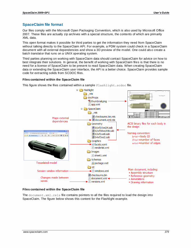
SpaceClaim 2009+SP1 User’s Guide
www.spaceclaim.com 379
SpaceClaim file format
Our files comply with the Microsoft Open Packaging Convention, which is also used by Microsoft Office
2007. These files are actually zip archives with a special structure, the contents of which are primarily XML data.
This open format makes it possible for third parties to get the information they need from SpaceClaim
without talking directly to the SpaceClaim API. For example, a PDM system could check in a SpaceClaim document with all external dependencies and show a 3D preview of the model. One could als o create a batch translator that runs on a UNIX operating system.
Third parties planning on working with SpaceClaim data should contact SpaceClaim for advice on how to best integrate their solutions. In general, the benefit of working with SpaceClaim files is that there is no need for a license of SpaceClaim to be present to read SpaceClaim data. When creating SpaceClaim
data or extending the SpaceClaim user interface, the API is a better choice. SpaceClaim provides sample code for extracting solids from SCDOC files.
Files contained within the SpaceClaim file
This figure shows the files contained within a sample Flashlight.scdoc file.
Files contained within the SpaceClaim file
The document.xml.rels file contains pointers to all the files required to load the design into
SpaceClaim. The figure below shows this content for the Flashlight example.

SpaceClaim 2009+SP1 User’s Guide
www.spaceclaim.com 380
For example, you can use the information in this file to determine all the parts required for a BOM by looking at the assemblyComponent relationship. In this case, it points to another file called Standard
Parts.scdoc. By opening this file and reviewing its components and subcomponents, you can generate
a BOM report.
There are three types of external file pointers:
assemblyComponent points to a file that contains subcomponents used in the assembly
drawingFormat points to the file used to format the drawing sheet
redlineComponent points to a 3D markup slide
There are also multiple internal file pointers to the geometry files, thumbnail, tessellated data, and window settings. The bodyGeometry Id provides the key to identifying the bodies described in the other XML and XAML files.
To view the data contained within SCDOC files
1. Copy the .scdoc file you want to view.
2. Replace the .scdoc file extension with the .zip file extension.
3. Extract the files within the zip file.
4. Open the folders and view the contents of the xml and xaml files with an XML viewer like XMLNotepad.
To edit the data contained within SCDOC files
You can safely modify some of the data contained within the .scdoc file; however, when creating
SpaceClaim data or extending the SpaceClaim user interface, the API is a better choice. The following steps explain how to edit an annotation within the Flashlight \SpaceClaim\document.xml.
1. Once you extract the files, open the document.xml with an XML viewer like XMLNotepad.
2. Search for the text of the annotation you want to change.
3. Edit the text.

SpaceClaim 2009+SP1 User’s Guide
www.spaceclaim.com 381
4. Save the file.
5. Create a new zip file containing all the previously-extracted files. Make sure that you do not
include the top-level folder.
6. Replace the .zip extension with a .scdoc extension.
7. Open the file in SpaceClaim to check your edits.
To view a tessellated model
Open the facets.xaml file with Internet Explorer, or any other xaml viewer.
To view a thumbnail of the file
Open the thumbnail.png file with any graphics program. The thumbnail is displayed in Windows Explorer.

SpaceClaim 2009+SP1 User’s Guide
www.spaceclaim.com 382
Customizing SpaceClaim You can customize SpaceClaim to best suit your working style. Mos t customization is done on the
SpaceClaim options window, accessible from the Application menu.
To customize SpaceClaim
1. Select SpaceClaim Options from the Application menu to display the SpaceClaim Options window.
2. Click the type of option you want to set from the navigation panel on the left.
You can use the up and down arrow keys to navigate the left panel.
3. Modify the options on the page.
4. Click OK to save all your changes and close the window.
If you try to enter a value that is out of the allowed range in the Options panel or the SpaceClaim Options dialog, you will see a red exclamation mark icon next to the field. You can hover over the
icon to see a tooltip that will explain the valid values for the option.
Option types
You can set the following option types:
Popular Change your application color scheme, set file options for importing and exporting, grid
size, application performance (speed vs. graphics quality), and customize the tools that are displayed while you are working in the Design window.
Detailing Change options for annotations and drawing sheets.
Color Change the color of the SpaceClaim application window.
Snap Change the objects snapped to while you are sketching and editing solids.
Units Set the units for dimensions, the sketch grid, and text height.
Support Files
Set the search path for support files, such as standard thread size tables.
Sheet
Metal
Set the thickness, bend, and relief defaults for sheet metal components.
Advanced Modify how your design changes are displayed in the Design window, whether tools and hints are displayed, enable background loading, change the language, customize the Spin,
Select, and Undo tools, reset the layout of the panels, and adjust the license warning.
Customize Add or remove tools and commands from the Quick Access toolbar.
Navigation Change the keyboard/mouse actions used for common navigation tasks.
Add-Ins Include or remove SpaceClaim add-ins.
License View and activate SpaceClaim licenses.
Resources Download sample designs, check for updates, contact SpaceClaim, or view information
about this version of SpaceClaim.
Popular options
Set the startup options, interface, application performance (speed vs. graphics quality), and customize the tools that are displayed while you are working with your design.

SpaceClaim 2009+SP1 User’s Guide
www.spaceclaim.com 383
To customize popular options
1. Select SpaceClaim Options from the Application menu to display the SpaceClaim Options window.
2. Click Color in the navigation panel on the left.
3. Modify the options on the page.
4. Click OK to save all your changes and close the window.
Graphics performance options
Rendering quality: Select a value from 1 to 7, where 1 is the lowest quality and 7 is the highest quality.
Select a low number to increase the speed of the application; select a high number to increase the quality of the graphics. Increasing graphics quality may lower the SpaceClaim's responsiveness to actions in the Design window. If you notice a delay when working with your design, modify this option to increase
application speed.
Anti-aliasing: The amount of smoothing applied to text, edges, and face boundaries in the Design window.
Recalculate Rendering: Click this button to update the 3D display in the Design window. This allows you to see the affects of any changes you made in the settings dialog.
Startup options
Show splash screen: Select this option to display the splash screen when you start SpaceClaim.
Show welcome screen: Select this option to display the Welcome window with links to tutorials, training videos, and other support resources when you start SpaceClaim.
Check for software updates: Select this option to use your internet connection to check for updates
each time you start SpaceClaim.
Interface options
Show tooltips: Select this option to display hints when you hover over tools, tool guides, and other icons. They briefly explain what will happen when you select the tool and provide some hints on how to use the
tool.
Show status messages in design window : Select this option to display messages from the status line (the lower left corner of the SpaceClaim window) in the design area. These messages provide hints and feedback while you work in SpaceClaim.
Show tool KeyTips: Select this option to enable keyboard shortcuts. Pressing and rel easing the Alt will display shortcuts that can be used to access the Quick Access toolbar, the Ribbon groups, and the tools in the Ribbon groups.
Show Journal tab in the Ribbon: Select this option to enable Journal tools, which you can use to save and play back a record of actions used to create a design.
Control options
Tool Guide position: Select Left, Right, Top, Bottom, or Not Shown.
Show mini-toolbar on selection: Select this option to display a small toolbar near your cursor when you right-click. The contents of the mini -toolbar depend on the tool you are using. You can click or scroll the middle mouse button to hide the mini-toolbar, and it fades as you move the mouse away from it. The mini -
toolbar is shown in the image below.

SpaceClaim 2009+SP1 User’s Guide
www.spaceclaim.com 384
Show radial menu: Allows you to use the radial menu to change select modes while other tools are active, and gives you quick access to the Pull, Move, Fill, and Combine tools. If you select this option, you
can select one or both of the following methods to open the radial menu:
Show after holding left mouse button for N ms
Show after clicking right mouse button, while holding left mouse button down
Show cursor arrows: Select this option to display arrows next to your cursor that indicate the directions
in which you can move your mouse to edit the selected object. The arrows also convey the change in size that will occur if you pull in that direction.
Arrow transparency: Adjust the slider to control the transparency of the cursor arrows. Move the slider to
the right to make the arrows more opaque; move it to the right to make them more transparent. The arrows are set to opaque in the image below.
Move handle size: Move the slider to increase or decrease the size of the Move handle relative to the
size of the Design window, as shown in the image below.
Grid guide: Change the position and size of the small toolbar displayed for the sketch grid. It is shown in its default position (corner) and size (small) in the image below.

SpaceClaim 2009+SP1 User’s Guide
www.spaceclaim.com 385
File import and export options
You can open and insert files from many other modeling applications into SpaceClaim for editing, and save your SpaceClaim designs as many different file types. If you work frequently with non -SpaceClaim files, we recommend that you set your file options to optimize the importing and exporting process for
your needs.
To customize import and export options
1. Select SpaceClaim Options from the Application menu to display the SpaceClaim Options window.
2. Click File Options in the navigation panel on the left.
3. Select a file type in the panel on the left to change options for just that type of file.
Descriptions of all options are listed below.
4. Click OK to save all your changes and close the SpaceClaim Options dialog.
If you try to enter a value that is out of the allowed range in the Options panel or the SpaceClaim Options dialog, you will see a red exclamation mark icon next to the field. You can hover over the
icon to see a tooltip that will explain the valid values for the option.
To set general file options
1. Click General in the panel on the left.
2. Check:
Use SpaceClaim color tones when importing to use the SpaceClaim color scheme for layers. This option is enabled by default to avoid fully saturated colors, on which highlighting is less visible. Faces of imported data will retain their original color tones if this option is turned off.
Create multiple documents when importing assemblies to open or insert a non-SpaceClaim assembly as multiple documents. When you save your design, click References to adjust where the documents are saved.
Use matching SpaceClaim documents for faster import if a design contains an external component that was previously imported and converted to the SpaceClaim .scdoc format,and you want to re-use that previously imported file.
Automatically save imported documents to immediately save an opened or inserted non-SpaceClaim file to an SCDOC file. (If you do not select this option, then opened or inserted files are not saved until you save the design.)
Improve imported data to improve a file when it is opened or inserted. De-selecting this
option imports the file without stitching, healing, or other improvements. As a result, the file appears more quickly, but you may need to perform these actions manually.
Improve data on export to improve a file when it is exported. This allows you to turn off
the behavior i f you don't want to merge faces and edges before a model is exported, such as exporting to Rhino.
Load model in background to orient large designs while they are loading.
Check Use lightweight assemblies to display a graphics-only representation of
SpaceClaim files in the Design window. These files become components when loaded, opened, or inserted. Check Import JT and CATIA models as lightweight assemblies to load JT and CATIA models as lightweight assemblies. Check Import assembly
structure only to display only the structure information about a SpaceClaim, JT, or CATIA, Pro/E, Solidworks, Inventor, or NX file in SpaceClaim's Structure tree.

SpaceClaim 2009+SP1 User’s Guide
www.spaceclaim.com 386
When you import a non-SpaceClaim file as a lightweight assembly, you can save the unloaded lightweight component as an SCDOC file with only rendering data (that is,
without geometry data). You can then open this SCDOC file in a new design and load it normally to include the geometry data.
Allow import of hidden components and geometry to open or insert hidden
components within CATIA v5, Parasolid, Solidworks, and SketchUp files, and turn off their visibility in the Structure tree.
Allow import of free curves and points to import curves and points that aren't attached to a surface or solid.
Allow export of hidden components to save components that have their visibility turned off in your design as hidden components when you save them as any other file type. This option is supported for ACIS, Rhino, SketchUp, and SAT/SAB formats.
To set ACIS file options
1. Select ACIS in the panel on the left.
2. Set the following options:
Convert ACIS bodies to SpaceClaim components to create components and use the
name of the ACIS bodies for the components. If you deselect this option, then the ACIS structure is used in the Structure tree.
Split body name by the following characters to insert the character between the part name and the body name, when the names are different. For example, with the character
set to a period, the name would be part.body. If you deselect this option, then the component name of imported components and solids are the same in the Structure tree.
Version to set the format of exported designs.
To set AutoCAD file options
1. Select AutoCAD in the panel on the left.
2. Set the Import options:
Insert Polyface Meshes and 3DFace entities into 3D as: Select how you want to
import polyface meshes in 3D into SpaceClaim.
Insert Polyface Meshes and 3DFace entities into drawing sheets as: Select how you want to import poly face meshes in drawings sheets.
3. Set the Export options:
Version: Select the AutoCAD version to set the format of exported designs.
Save as Black and White : Remove color information from exported designs.
4. Set the DWG options for import and export:
Open DWG to use the OpenDWG 2.7.03 library. For import it will attach DWG dimensions to the geometry in your design. Use this option to import DWG files with sketch curves and text that will be imported into a design, or 2D entities that will be inserted in a drawing sheet. For export it will keep dimensions you created in SpaceClaim
attached to the geometry in your design.
Autodesk Real DWG to use Autodesk's translator. For import it will disconnect DWG dimensions from the geometry in your design. Use this option to import DWG files with
3D bodies. For export it will disconnect dimensions from the geometry in your design.
When the General option Improve imported data is enabled and the AutoCAD option Insert Polyface Meshes and 3DFace entities into 3D is set to Solid models, then the seam edges
between coincident faces are removed when you import AutoCAD files.

SpaceClaim 2009+SP1 User’s Guide
www.spaceclaim.com 387
The example below shows a model imported without these two options on the left and with the options enabled on the right.
To set CATIA file options
1. Select CATIA in the panel on the left.
2. Check Import part manufacturing information to include product manufacturing information when you open or insert CATIA designs.
If you select this option, and you previously selected Import assembly structure only in the General file options, that option will be deselected.
3. Select the CATIA version to set the format of exported designs.
To set IGES file options
1. Select IGES in the panel on the left.
2. Select an Import Method:
Use facewise connections to attempt to stitch everything together and make a solid i f possible. With this option selected, the import may fail i f the model is corrupt.
Import faces independently to import models as a collection of individual surfaces, skipping only the surfaces that are corrupt.
3. Select an Export SpaceClaim body option:
Manifold Solid B-Rep Object (MSBO - Type 186): MSBO defines a manifold body with all the necessary topology information like shells, faces, loops, edges and vertices.
Trimmed surfaces (Type 144): The boundaries of these surfaces will be represented by
Curve on a Parametric Surface Entity (Type 142).
Bounded surfaces (Type 143): The boundaries of these surfaces will be represented by Boundary Entity (Type 141). The boundary entity will refer to model space curves and surface parametric curves, with preference set to model space curves.
To set JT Open file options
1. Select JT Open in the panel on the left.
2. Select Override quality to change the faceting setting for exported files so it is different from the graphics facetting setting.
Coarse, Medium, Fine to use the deviation and angle preset values.
Custom to use the Deviation and Angle sliders to set a custom resolution.
Resolution indicates the number of sides of a polygon used to represent a circle. The deviation is the difference in distance between the circle’s radius and the polygon’s radius.
The angle is the angle between the edge of the polygon and a tangent drawn through the circle at the same point.
To set OBJ file options
1. Select OBJ in the panel on the left.

SpaceClaim 2009+SP1 User’s Guide
www.spaceclaim.com 388
2. Select Override quality to change the faceting setting for exported files so it is different from the graphics facetting setting.
Coarse, Medium, Fine to use the deviation and angle preset values.
Custom to use the Deviation and Angle sliders to set a custom resolution.
Resolution indicates the number of sides of a polygon used to represent a circle. The deviation is the difference in distance between the circle’s radius and the polygon’s radius.
The angle is the angle between the edge of the polygon and a tangent drawn through the circle at the same point.
To set Parasolid file options
1. Select Parasolid in the panel on the left.
2. Select the Parasolid version to set the format of exported designs.
To set PDF file options
1. Select PDF in the panel on the left.
2. Select Geometry (PRC B-Rep) to save the geometry of the design, such as equations for
surfaces, edges, etc.
3. Select Facets only (Universal 3D) to save only the triangles that make up the rendering of the solids (that is, an approximation).
To set Rhino file options
1. Select Rhino.
2. Select Convert Rhino layers to SpaceClaim layers on import to import layers.
3. Select Convert SpaceClaim layers to Rhino layers on export to export layers.
To set STEP file options
1. Select STEP in the panel on the left.
2. Select an Import Method:
Use facewise connections to attempt to stitch everything together and make a solid i f
possible. With this option selected, the import may fail i f the model is corrupt.
Import faces independently to import models as a collection of individual surfaces, skipping only the surfaces that are corrupt.
3. Select the STEP protocol to use to format exported designs.
To set Pro/ENGINEER options
1. Select Pro/ENGINEER in the panel on the left.
2. Select Allow import of Quilts i f you want to import quilts. A Quilt in Pro/ENGINEER is a collection of individual surface bodies.
To set STL file options
1. Select STL in the panel on the left.
2. Select one of the following output settings:
Binary to store the file data in binary format.
ASCII to store the file data in ASCII format.
3. Select the number of files you want exported in the File section. One file is exported per design, component, or body.

SpaceClaim 2009+SP1 User’s Guide
www.spaceclaim.com 389
4. Select one of the following to set the resolution of the output file:
Coarse, Medium, Fine to use the deviation and angle preset values.
Custom to use the Deviation and Angle sliders to set a custom resolution.
When exporting to STL, resolution indicates the number of sides of a polygon used to represent a circle. The deviation is the difference in distance between the circle’s radius and the polygon’s radius. The angle is the angle between the edge of the polygon and a tangent
drawn through the circle at the same point.
Appearance options
You can adjust SpaceClaim's appearance, such as its menu bar style and color schemes. This options page also contains placeholder elements for future color customization options.
To set color options
1. Select SpaceClaim Options from the Application menu to display the SpaceClaim Options window.
2. Click Appearance in the navigation panel on the left.
3. Modify the options on the page.
4. Click OK to save all your changes and close the window.
Skin
Color scheme: Select Silver, Blue, Black, or Custom from the menu. This option controls the color of title bars and menus for computers running Microsoft® Vista®.
Ribbon style: Choose between Fluent (Office 2007) or Scenic (Office 2010) style ribbon bar styles.
Reset Docking Layout: Click this button to return the layout of the docking panels and SpaceClaim windows to their original locations.
General
Design color scheme : Select a color scheme from the menu. This option controls the color scheme used
in the Design window. You can choose between two pre-set color schemes: White Background or Black Background. Elements displayed in the design area will change to colors that work well for the background color.
You can change the colors for other elements. Click the color next to an individual element and choose a new color from the drop-down. Select colors from the Custom, Web, or System palettes.
Click Reset to change all the colors back to the SpaceClaim defaults.
Drawing color scheme : These options are not yet implemented.
Snap options
You can set snapping options for sketching and editing solids. Units for snap options are set by your Units
options for all new documents.
To customize snap options
1. Select SpaceClaim Options from the Application menu to display the SpaceClaim Options window.
2. Click Snap from the navigation panel on the left.
3. Modify the options on the page.
4. Click OK to save all your changes and close the window.

SpaceClaim 2009+SP1 User’s Guide
www.spaceclaim.com 390
If you try to enter a value that is out of the allowed range in the Options panel or the SpaceClaim Options dialog, you will see a red exclamation mark icon next to the field. You can hover over the
icon to see a tooltip that will explain the valid values for the option.
To set incremental options for sketching on the sketch grid
1. Check Angular snap to snap to objects while sketching.
2. Enter the angle increment you want to snap to when you select the Snap to angle option in
Select, Move, and Sketch tools.
To enable snapping to objects when sketching on the sketch grid
1. Check Enable snapping in sketches to snap to objects while sketching.
While you sketch, objects you can snap to are highlighted. The points to which the sketch tools
are snapping appear as messages in the status bar.
2. Check the box next to each item in the list to determine which objects you can snap to while sketching:
Line - Snap points along lines (at intersections with sketch grid) indicated by rectangles
End point - Snap points at all end points indicated by squares
Midpoint - Snap point at center of lines indicated by triangles
Arc/circle center - Snap points at center of arcs and circles indicated by circles
Tangent from end point - Snap points at tangent angle to end points indicated by tangent guides
Perpendicular from end point - Snap points perpendicular angle to end points indicated by perpendicular guides
Tangent/perpendicular from line - Snap points at tangent and perpendicular angles along lines indicated by tangent and perpendicular guides
Parallel to line - Lines parallel to the sketched line indicated by highlighting
Parallel to grid - Snap enabled parallel to the grid when snap to grid is disabled
Grid - Snap enabled to the grid
To set incremental options for editing solids
1. Check Linear snap to snap to constrain to a linear increment and set the linear interval for tool movements in the Incremental area.
For example, if you set the Linear increment to 1 mm, you will pull to whole millimeters instead of fractions of millimeters.
2. Check Angular snap to snap to constrain to an angle increment and set the degree interval for
tool movements in the Incremental area.
For example, if you set the Angular increment to 5 degrees, you will move in larger increments than if set to 1 degree.
To set snapping options for editing solids
1. Check Enable snapping to solids with the Shift key to snap when you press and hold Shift
using any tool.
2. Check the box next to each situation or object in the list to determine when a tool will snap while editing solids:
Face parallel - Snap to a parallel face

SpaceClaim 2009+SP1 User’s Guide
www.spaceclaim.com 391
Rotate parallel to face - Snap to a parallel face when rotating
Rotate perpendicular to face - Snap to a perpendicular face when rotating
Edge - Snap to any edge
Cylinder radius - Snap to the radius of a cylinder
Round radius - When creating a round, snap its radius the radii of existing rounds on the component
To set the nudge options
You can change the values for Distance or Angle:
Normal - The nudge increment when you press Alt and an arrow key.
Small - The nudge increment when you press Alt + Ctrl and an arrow key.
Big - The nudge increment when you press Alt + Shift and an arrow key.
Examples
Snapping to the midpoint of a line
Editing a solid with angular snap set to 15 degrees

SpaceClaim 2009+SP1 User’s Guide
www.spaceclaim.com 392
Snapping to a round radius
Units options
You can set the units for dimensions, the sketch grid, and text height.
To customize units
1. Select SpaceClaim Options from the Application menu to display the SpaceClaim Options window.
2. Click Units from the navigation panel on the left.
3. Select one of the following from the Units settings for drop-down list:
All New Documents to create a default detailing style for all your designs. These
settings will not affect any currently open documents.
This Document to set options for the current design only.
4. Modify the options on the page.
5. Click OK to save all your changes and close the window.
If you try to enter a value that is out of the allowed range in the Options panel or the SpaceClaim Options dialog, you will see a red exclamation mark icon next to the field. You can hover over the icon to see a tooltip that will explain the valid values for the option.
Units
Type: Select Metric or Imperial from the menu.
Length: Select the default units used for length. Angles are always shown in degrees.
Decimal/fraction: If you use Imperial units, you can select Decimal or Fraction to display distance
measurements that are less than 1 unit.
Mass: Select the default units used for mass.
Density: Select Independent to specify the density units from the density fields or Derived to calculate
the units from your selections for length and mass.
Symbol: Select the abbreviation you want displayed for unit type you selected for Length.
Primary precision: The number of decimal places you want displayed for distance measurements for the
primary units.
Use tight tolerances: When this option is selected, tolerances are rounded to a value that gives a tighter tolerance when you convert from one unit system to another (Metric or Imperial). When the option is not

SpaceClaim 2009+SP1 User’s Guide
www.spaceclaim.com 393
selected, the tolerance is rounded to the nearest value. This is used for dual dimensions or when a dimension from the design window is shown in the drawing window with a different unit setting than the
design window. The purpose is to not lose any precision when converting and from one unit system to another.
Show symbol in user interface : Select this option to display the units abbreviation in SpaceClaim. The
abbreviation will appear in measurement fields, such as a distance field when you pull a face.
Show symbol in annotations: Select this option to display the units abbreviation after the measurement in annotation dimensions.
Show trailing zero: Select this option to display trailing zeros in decimal measurements.
Show "-" separator: Select this option to display a hyphen between whole values and fractions.
Dual dimensions: Select this option to display annotation dimensions in both Metric and Imperial. The
unit type you have selected is displayed first and the other is displayed in square brackets. You can see a preview of the display below this option category.
Secondary precision: The number of decimal places you want displayed for distance measurements for
the secondary units.
Grid
Reset to Defaults: Click this button to reset the grid settings to the SpaceClaim defaults.
Minor grid spacing: Type the distance you want between the smallest grid lines.
Number of grid lines per major: Type the number of smaller grid lines between larger, darker grid lines.
Text
Text height units: Select a unit type for note text.
To convert an existing solid or surface from millimeters to inches
1. Change the units to inches as described above.
2. Select the Pull tool in the Edit ribbon group on the Design tab.
3. Select the object you want to convert.
4. Scale the object by 25.4.
Support file options
You can specify the directories in which you store support files, such as drawing sheet formats or thread size tables. Drawing sheets contained in these directories are displayed within the Format tool.
To set the location of support files
1. Select SpaceClaim Options from the Application menu to display the SpaceClaim Options window.
2. Click Files from the navigation panel on the left.
3. Click Add or Brow se and navigate to the file or directory you want to include. (You can also select the path and click Remove to remove it.)
4. Select a path and click Move Up or Move Down to order the file paths.
5. Click OK.
Sheet Metal options
You can set the wall thickness, bend, and relief defaults for sheet metal components. These defaults can
be changed for each component or bend by selecting the component or bend and modifying the property
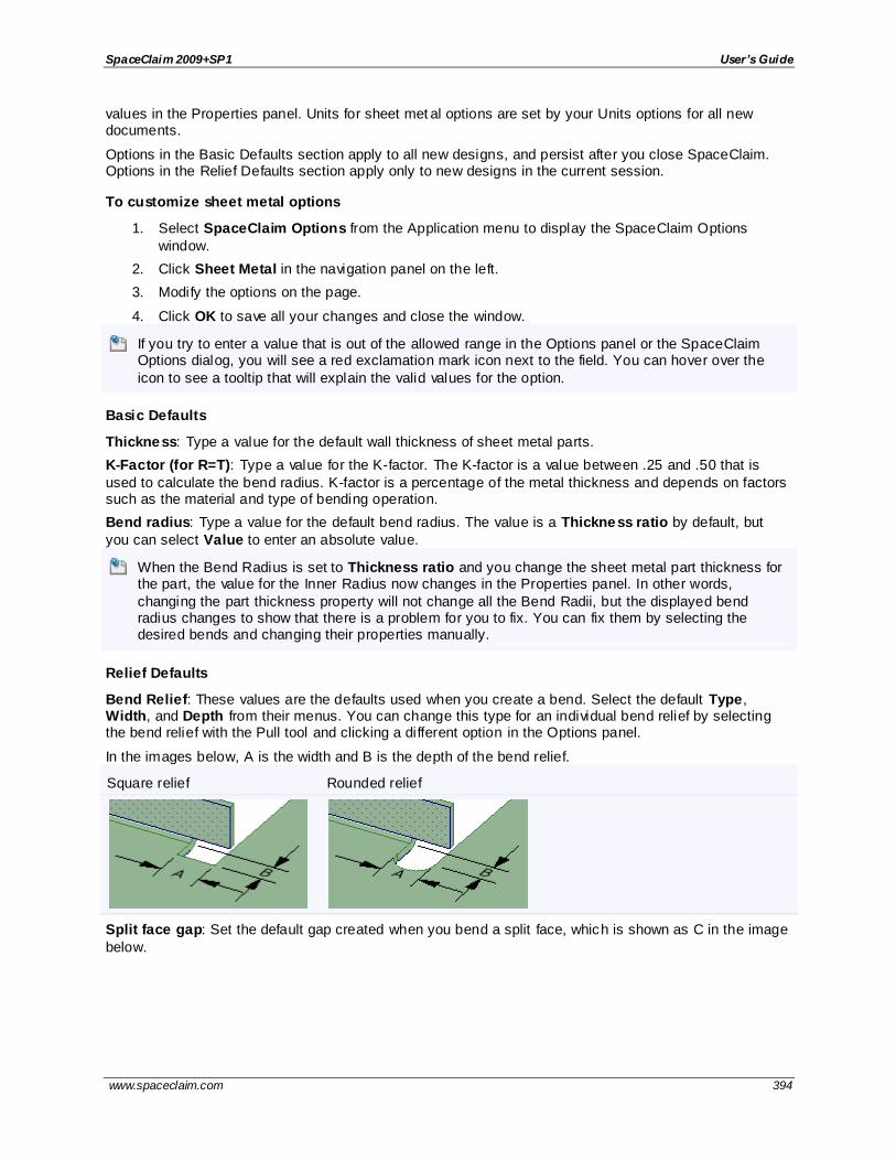
SpaceClaim 2009+SP1 User’s Guide
www.spaceclaim.com 394
values in the Properties panel. Units for sheet met al options are set by your Units options for all new documents.
Options in the Basic Defaults section apply to all new designs, and persist after you close SpaceClaim. Options in the Relief Defaults section apply only to new designs in the current session.
To customize sheet metal options
1. Select SpaceClaim Options from the Application menu to display the SpaceClaim Options
window.
2. Click Sheet Metal in the navigation panel on the left.
3. Modify the options on the page.
4. Click OK to save all your changes and close the window.
If you try to enter a value that is out of the allowed range in the Options panel or the SpaceClaim Options dialog, you will see a red exclamation mark icon next to the field. You can hover over the
icon to see a tooltip that will explain the valid values for the option.
Basic Defaults
Thickness: Type a value for the default wall thickness of sheet metal parts.
K-Factor (for R=T): Type a value for the K-factor. The K-factor is a value between .25 and .50 that is
used to calculate the bend radius. K-factor is a percentage of the metal thickness and depends on factors such as the material and type of bending operation.
Bend radius: Type a value for the default bend radius. The value is a Thickness ratio by default, but
you can select Value to enter an absolute value.
When the Bend Radius is set to Thickness ratio and you change the sheet metal part thickness for the part, the value for the Inner Radius now changes in the Properties panel. In other words,
changing the part thickness property will not change all the Bend Radii, but the displayed bend radius changes to show that there is a problem for you to fix. You can fix them by selecting the desired bends and changing their properties manually.
Relief Defaults
Bend Relief: These values are the defaults used when you create a bend. Select the default Type, Width, and Depth from their menus. You can change this type for an individual bend relief by selecting the bend relief with the Pull tool and clicking a different option in the Options panel.
In the images below, A is the width and B is the depth of the bend relief.
Square relief Rounded relief
Split face gap: Set the default gap created when you bend a split face, which is shown as C in the image
below.

SpaceClaim 2009+SP1 User’s Guide
www.spaceclaim.com 395
Corner relief: Set the default depth of corner reliefs, which is shown as D in the image below.
If you change the width or depth for these option you can select:
Thickness ratio to change the relief width and depth based on the thickness of the wall.
Value to specify the exact width and depth of the bend relief.
Export
Round all sharp corners at DXF export: Select this option to round all the edges in your design whose
neighboring faces are not co-planar when you export a DXF file. You can set the round radius values if you select this option.
Advanced options
Modify how your design changes are displayed in the Design window, whether tools and hints are displayed, enable background loading, change the language, customize the Spin, Select, and Undo tools, reset the layout of the panels, and adjust the license warning.
To set advanced options
1. Select SpaceClaim Options from the Application menu to display the SpaceClaim Options window.
2. Click Advanced in the navigation panel on the left.
3. Modify the options on the page.
4. Click OK to save all your changes and close the window.
If you try to enter a value that is out of the allowed range in the Options panel or the SpaceClaim
Options dialog, you will see a red exclamation mark icon next to the field. You can hover over the icon to see a tooltip that will explain the valid values for the option.
General
Animate changes to view projection: Select this option to animate the steps when you select a view.
Animate Full Pull: Select this option to animate all the steps when you select the Full Pull option to revolve, sweep, or blend your design.
Show previous selections with pre-highlight hint: Select this option to highlight all the geometry you
last acted on that includes the selected vertex, edge, or face. If you click again with the Select tool, the previously selected group will be selected for you with that one click.
Auto-extrude/revolve sketches in Section mode : Select this option to automatically extrude or revolve
in section mode. As you sketch in Section mode, lines that begin on an existing edge are extruded to form

SpaceClaim 2009+SP1 User’s Guide
www.spaceclaim.com 396
surfaces, and closed surfaces form solids. If the line begins on a solid, the line is finished automatically when you click another point on the solid.
Enable assembly mechanisms: Select this option if you want assembly relationships to be solved when components are moved. This allows you to create complicated mechanisms by letting SpaceClaim reposition and reorient components as necessary in order to satisfy assembly constraints. With this option
disabled, a constraint will only affect the component which contains the assembly constraint. Look in the Structure tree to see which components contain constraints.
Language: Select a language from the menu. You must restart SpaceClaim for this change to take effect.
Maximum undo steps: Type the number of actions you want available for undo. We recommend that this value be set to at least 50.
Selection
Hit radius: Type the number of pixels your cursor can be from the object you want to select.
Automatically calculate Power Selection results: Select this option to automatically display objects in
the Selection panel. You do not need to click to search when power selecting. Objects similar to the
selected object are automatically displayed in the Related list. This option is on by default.
Power Selection relative tolerance : Type a percentage to change the relative tolerance used when searching in the Selection panel. Enter a non-zero percentage to find objects with similar, but not exactly
the same dimensions when power selecting. For example, if you enter 10% in this option field, select a 10
mm radius round in your design, then click in the Selection panel, rounds with a radius between 9 mm
and 11 mm will be returned in the All rounds equal to 10 mm results list. The default is 1%. Adjust this value to 0% to detect perfect rounds exactly or increase it to find imported rounds.
Behavior
Preview before modifying: Select when you want interim calculations performed when modifying solids from the menu. If this option is turned on, the preview of a change is displayed as a rough wireframe model rather than a rendered, 3D model. If you work with very large designs, a wireframe preview can be
faster than doing the calculations necessary to render the change as a shaded 3D model. Select:
Auto to allow SpaceClaim to determine when to render the preview based on the size of the component and the capabilities of your graphics card.
On to always display changes as rough wireframe previews rather than rendered previews.
Off to always render the preview instead of displaying it as a wireframe model.
Enable geometry convergence : Select this option if you want SpaceClaim to help you when you are moving solids together so that the edges (such as rounds) converge perfectly. If this option is enabled,
when you are moving solids together, SpaceClaim will display a progress bar as it performs the convergence steps.
Show cross sections in sketch: Select this option to display cross sections of solids with hatching. You
might want to disable this option if you are working with complicated cross -sections.
Fill cross section: Controls the visualization of a cross-sectioned solid in Section mode. If this option is on and you view a section through a body, the body will filled with color.
Show arc centers: Select this option to display small crosses on the sketch grid at the center of circles, ellipses, polygons, and arcs.
Top view direction: Allows you to change the top view to Z or Y. This setting is saved with the document
and only applies to new documents. You may want to change this setting when you import drawings from other CAD applications that use a different upward direction. This option is automatically set to Y when you run SpaceClaim with an ANSYS license. This gives your design the same orientation in SpaceClaim
and ANSYS.

SpaceClaim 2009+SP1 User’s Guide
www.spaceclaim.com 397
Examples
Extruding while sketching in Section mode
Quick Access toolbar options
The Quick Access toolbar (QAT) is located on the title bar. The Ribbon is the menu bar that contains all
the tools in groups. You can add or remove tools from this toolbar and control the placement and display of the Ribbon.
To customize the Quick Access toolbar
1. Click next to the Quick Access toolbar.
2. Select any items you want to appear in the toolbar.
3. Select Place Quick Access Toolbar below the Ribbon to create a separate toolbar on the
SpaceClaim interface.
4. Select Customize Quick Access Toolbar to display the SpaceClaim options window. (Any changes you made in the previous steps are saved automatically.)
You can also select SpaceClaim Options from the Application menu and click Customize.
5. Select the ribbon group that contains the tool you want to include in the QAT from the Choose commands from drop-down menu.
6. Click the tool you want to include and click Add.
Select a tool and click Remove to remove it from the QAT.
7. Click OK.
To temporarily minimize the ribbon bar
Double-click the name of the active tab or press Ctrl -F1. Double-click a tab or press Ctrl-F1 again to restore the ribbon bar.
To keep the ribbon bar minimized
1. Click next to the Customize Quick Access toolbar.
2. Select Minimize the Ribbon to hide the ribbon when you are working in the Design window.
To use the ribbon while it is minimized, click a tab to display the ribbon bar temporarily.
To restore the ribbon bar
1. Click next to the Customize Quick Access toolbar.

SpaceClaim 2009+SP1 User’s Guide
www.spaceclaim.com 398
2. Select Maximize the Ribbon.
Navigation options
Navigation themes are sets of keyboard/mouse settings used as shortcuts for common navigation tasks. You can select from alternative themes if you want to match another CAD application you are familiar with. You can also modify individual settings to create a custom theme.
To set navigation options
1. Select SpaceClaim Options from the Application menu to display the SpaceClaim Options window.
2. Click Navigation in the navigation panel on the left.
3. Select a Theme, which will change the navigation style for Spin, Pan, Zoom, and Zoom-in to several pre-set navigation themes.
4. Change the key and mouse combinations used for Spin, Pan, Zoom, and change the Zoom-in
direction.
5. Select an option in the Mouse Wheel section if you want to change the zoom behavior:
Zoom in Quick Zoom (Ctrl+MMB) and in Zoom mode : The mouse wheel only zooms while
you are in zoom mode or if you hold Ctrl and drag with the middle mouse button. Click Zoom in the Orient group on the Design tab to toggle zoom mode.
Zoom while in Spin/Pan/Zoom (around center) mod e: The mouse wheel zooms while you
are in Spin, Pan, and Zoom modes. If you don’t select this option, you can hold Ctrl to zoom while in these modes.
Zoom always (hold Ctrl to query select): The mouse wheel always zooms. Hold the Ctrl key
to use the mouse wheel to select objects that are behind other objects (also known as query selection).
Select a Spin Method:
Arcball: Rotates the view using the spot where you start dragging as the rotation axis. Imagine the axis running straight up and down from your mouse position and perpendicular to your current view. This is the spin method that has always been used in SpaceClaim and is the
default. Navigation in most 3D CAD systems works like this.
Turntable: Rotates the view using the top of the parts as the up direction and the location of your mouse as the rotation axis. This is the spin method commonly used in architectural CAD
packages.
Select Show spin center to display the axis about which you are spinning your design when you use the Spin tool.
Select Rotate about pre-selected object to spin around the highlighted edge when you are using the Spin tool.
You may want to uncheck this box if you are working with large or complicated designs. You can
press Alt and to rotate around a highlighted object whether or not this option is selected.
Click Reset to delete the Custom theme and restore the default settings.
Click OK to save all your changes and close the window.
Alternative navigation themes
CAD Application Navigation theme (closest match)
SpaceClaim Default

SpaceClaim 2009+SP1 User’s Guide
www.spaceclaim.com 399
Pro/ENGINEER® Default
Solid Edge® Default
CATIA® Alternative 1
Rhino® Alternative 2
ANYSYS® Alternative 3
SolidWorks® Alternative 3
ALGOR® Alternative 3
KeyCreator® Alternative 3
Inventor® Alternative 4
You can also modify the individual control settings to create a custom theme.
Configuring windows
SpaceClaim has several docking windows that are initially docked along the left side of the application.
You can minimize these panels, detach them, or dock them to different sides of the application. You can also dock and detach your design windows.
To minimize a panel
Click the thumbtack icon to minimize the docked panel. Mousing over a minimized panel expands the
panel while the cursor is over it. Once the cursor leaves the expanded panel, it returns to its minimized state.
To maximize a panel
Click the thumbtack icon to "stick" the panel to the application window.
To detach a panel or window
Drag a panel by its title bar to detach it. Drag a design window by its tab to detach it.
To dock a panel or window
Drag a panel or window by its title bar or tab. As you move the panel or window over the application, icons indicate possible docking positions.
Mouse over an icon to preview the docked location. Release the mouse button to dock the panel at that location.
To return docked panels to their default layout
1. Select SpaceClaim Options from the Application menu and select Appearance.
2. Click Reset Docking Layout.
3. Click OK.
Customizing the Welcome window
The layout and contents of the SpaceClaim Welcome window can be customized by editing a single XML file. You can add or remove buttons, edit the icon for a button, control the layout of buttons, and determine the action executed when a button is pressed.
The following button actions are supported:

SpaceClaim 2009+SP1 User’s Guide
www.spaceclaim.com 400
Launch a video – any media format that the operating system of the computer displaying the Welcome window can play
Launch a Web page – uses the default browser
Launch a SpaceClaim Help page – opens SpaceClaim’s html-based help to a specific page of its contents
Load a SpaceClaim model – from any file format that SpaceClaim opens in the running instance of
SpaceClaim that the Welcome screen is attached to
Launch any other executable that the operating system can handle
The XML file: Welcome.xml
The XML file Welcome.xml consists of a list of tags that contain the information for displaying and
executing the buttons in the dialog. In the following example, a new group named ―Getting Started‖ is created, with one button named ―Introduction‖ in it.
XML Elements
The following tags are used in Welcome.xml to specify the content and behavior of the Welcome screen:

SpaceClaim 2009+SP1 User’s Guide
www.spaceclaim.com 401
File structure and versioning
When the Welcome screen launches, it looks first for the Welcome.xml file and uses that file to set the
layout and behavior of the buttons. It looks first in the %APPDATA%\SpaceClaim\Welcome directory
(typically C:\Documents and Settings\user\Application Data\SpaceClaim\Welcome\) and
then in SpaceclaimInstallDirectory\Library\Welcome\ for the xml file.
The paths to files (example: <DocumentPath>folder\intro.scdoc</DocumentPath>) used in
Welcome.xml should be relative paths from the location of welcome.xml. This means that in order to
create a custom Welcome screen, the Welcome.xml file should be placed in either of these locations
with the supporting files and images.
Once the Welcome screen has loaded, it checks the SpaceClaim server (i f connected to the internet) to see if a newer version of Welcome.xml exists. If it does, it automatically downloads it and replaces the
current Welcome screen display. This means that if a user wishes to have a custom Welcome screen created and used by SpaceClaim, they should assign a large version number in the <Version> tag in Welcome.xml so that SpaceClaim will not download and overwrite the custom version with a newer
version.
Lastly, in order to minimize the size of files included with a SpaceClaim install, the Welcome sc reen need
not have the files referenced in the Welcome.xml . For example, if the xml file uses the link
<Link>Videos\intro.wmv</Link> (to a possibly large video file) and the video file is not present on the
user’s machine, when the button is pressed to watch the video (and only when the button is pressed) the user will be prompted to download the video from the SpaceClaim server (i f it exists). This way large videos can be stored on a server and only accessed if and when the user tries to watch them.
Additional notes
The <Link> tag can be used to open any executable or windows document.
The preferred button image type is .png with a transparent background. This approach produces the best highlighted appearance when the button is pressed.
The <Tooltip>, <Link>, <HelpId>, and <DocumentPath> tags are optional.

SpaceClaim 2009+SP1 User’s Guide
www.spaceclaim.com 402
The <Name> tag for an item must be unique. This tag is used internally to identify buttons so that they can use different translated text.

SpaceClaim 2009+SP1 User’s Guide
www.spaceclaim.com 403
Working with sheet metal You can use SpaceClaim to create sheet metal designs and components.
SpaceClaim recognizes a component as sheet metal i f it consists of only planar, cylindrical, and conical faces, and when faces are offsets of the same size.
Creating a sheet metal design
You can create a new sheet metal design using SpaceClaim's sketch and editing tools. See Converting a design to sheet metal if you have already modeled the part.
When you pull walls up on a design, the side edges of the new wall will follow the angles of its neighbors. This angle is usually 90°, but can be almost any angle. If the neighboring walls are obtuse angles, the neighbor wall has to be less than 135° for the new wall to follow along the neighbors.
To create a new sheet metal design
1. Right -click the component or top-level design and select Sheet Metal.
When you convert a component to sheet metal, all of the bodies in the component become sheet metal parts. Remember to make the component active before you pull a surface into a solid, or the solid will be created in the active component, which may not be set as sheet metal.
2. Sketch the sheet metal wall.
3. Click Pull and pull the face of the sheet metal wall.
The pull snaps to the thickness defined in the Properties panel.

SpaceClaim 2009+SP1 User’s Guide
www.spaceclaim.com 404
4. (Optional) Change the junction type, bend relief type, and bend behavior in the Options panel while the Pull tool is active.
See Changing junctions, Creating and changing bend reliefs, and Changing bend behavior options.
5. Select a linear edge of the sheet metal solid.
6. Click on a pull arrow or press Tab to change the pull direction.
If the pull arrows do not appear, then the selected edge cannot have material added to it.
7. (Optional) Drag the yellow balls along the edge if you want to pull a partial wall.
8. Pull the edge to create a wall.
If you bend a wall back over itself to create a hem, a 0.0001 mm gap is created automatically. You can also use the Move tool to drag an existing wall back onto a neighboring face to make a
hem.
If you pull the top edge of a wall in the direction along the face with the No Overlap option selected, the new wall is offset by one thickness from the top. If you pull the bottom edge, the wall
is offset one thickness from the bottom. If you select Partial overlap or Full overlap, the wall is extended without a junction. If you select Bend, an S curve is created. If you select Remove Junction, the junction no longer acts as a sheet metal junction.
9. (Optional) Select the sheet metal component in the Structure tree and edit the sheet metal properties in the Properties panel.
See Changing sheet metal part properties.
You can use the Up To tool guide when you pull sheet metal parts or walls. A slight gap (.0001 mm) is created between the edge and the object you pull up to.

SpaceClaim 2009+SP1 User’s Guide
www.spaceclaim.com 405
Examples
Dragging a yellow ball end point to pull a partial wall.
Pulling a wall with an adjacent wall creates a matching angle in the end of the new wall.
Editing a sheet metal design
In addition to the regular functions associated with the Pull and Move tools, several additional functions are available when you work with sheet metal parts.
Creating and changing bend reliefs
These reliefs are automatically created when you pull a partial wall. You can select the bend relief type from the Options panel to specify the type of bend relief that will be created when you pull it.
Dragging a yellow ball end point to pull a partial wall creates a bend relief.
A message appears in the status bar i f a relief cannot be created, such as when it is too close to the side.
After you create a bend with a relief, you can select the bend and change the relief type in the Options panel, and you can edit the type, depth, and width in the Properties panel.
Relief type
Icon Example
Round
Square

SpaceClaim 2009+SP1 User’s Guide
www.spaceclaim.com 406
Rip
See Sheet Metal options for information about changing the dimensions of bend reliefs.
To change a bend relief type
1. Select the bend that is adjacent to the relief you want to change.
Click on the edge or face highlighted in red to select the bend:
2. Select a bend relief type in the Options panel.
The bend relief(s ) adjacent to the bend will change.
Changing junctions
The junction type can be changed for corners with or without reliefs.
Junction type Icon Example
No Overlap
Partial Overlap
Full Overlap
Bend
Flange
Reverse Junction
Hard Edge
Removes rips and bends from the geometry and returns it to a shell, where there is no inside or outside radii. (You can also rotate a 180° "hem" to create a 90° flange.)
Remove Junction Removes the junction behavior, leaving only the geometry.
To change junctions
Select the edge of a corner or bend junction and select a junction type in the Options panel or the mini -toolbar. In the example below, the junction has been changed from No Overlap to Full Overlap using the
mini-toolbar:
Here a bend junction is changed from a Bend to a Full Overlap:

SpaceClaim 2009+SP1 User’s Guide
www.spaceclaim.com 407
To convert an S junction to a no-overlap junction
Click the Pull tool, select any edge on the junction, and click No Overlap in the Options panel or mini-
toolbar:
To reverse a junction
Click the Pull tool, select the edge of a junction as shown below, and click Reverse Junction in the
Options panel or mini-toolbar.
You must select the edge shown when you reverse a flange junction. You cannot select other edges
of the flange to reverse its direction.
Making watertight corners
Watertight corners are sheet metal corners that don't have reliefs, so to make them you simply remove the reliefs. Parts with watertight corners can be unfolded and modified just like any other sheet metal part.
To make a corner watertight
1. Select the faces of the corner, like this:
2. Click Fill in the Edit group on the Design tab.
The corner is now watertight:

SpaceClaim 2009+SP1 User’s Guide
www.spaceclaim.com 408
To convert a watertight corner to a corner with reliefs
1. Select the edge or point where the bends meet, as shown below.
or
2. Click Pull in the Edit group on the Design tab.
3. Click Corner relief in the Options panel.
Changing bend behavior options
The bend behavior options control where bend radii are created in relation to adjacent walls.
The following options are found in the Options panel when the Pull tool is active and a sheet metal part is selected.
Use edge location and direction: When you pull a sheet metal edge, the location of the bend
radius depends on the edge you select and the direction you pull.
When you pull away from the other edge (A), the selected edge becomes an inside corner. When you pull across the other edge (B), the selected edge becomes an outside corner.
Maintain inside surface : The length of the inside surface of the wall is maintained.
Maintain outside surface : The length of the outside surface of the wall is maintained.
Create bends from sketch curves
You can create bends in sheet metal parts using imprinted edges and curves in layout planes.
If the imprinted edge or sketch curve selection is primary, then the wall is bent upward.
If the selection is secondary, or Alt-selected, then the wall is bent downward.
You can select multiple primary and secondary edges and/or sketch curves and bend them at the same time.
The sketched lines and edges do not have to be at 90° angles to the existing faces (which will make skewed bends), as shown in the examples below.
The extreme left corner of the body is fixed when this is done to an e ntirely flat part and the entire part is
bent up.

SpaceClaim 2009+SP1 User’s Guide
www.spaceclaim.com 409
To create a 3D sheet metal part from a flat DXF file, import the file, use Fill to fill the curves, thicken the part, and use the sketch curves to apply bends.
The input is the bend angle from the flat state, measured as the external angle at the outside mold line. A symmetric bend is made about the selected bend line, as shown below.
To add a bend to a sheet metal part using a sketch curve
1. Draw sketch curves on an existing sheet metal face.
The sketch curve does not have to extend the full length of the bend.
You can also draw sketch curves and add them to a layout plane:
a. Draw a line where you want to add the fold.
b. Select the line and click Plane in the Insert group on the Design tab.
2. Click Pull in the Edit group on the Design tab.
3. Select one or more sketch curves or imprinted edges.
Hold Ctrl to select more than one curve or edge.
4. (Optional) Click on the yellow arrows to reverse the direction of the bend.
5. (Optional) Hold Alt and select the face you want to remain stationary.
If you don't select a stationary face, then the left bottom corner point is used as the anchor.
6. Bend along the sketch curve:
To make a 90° bend, click the bend icon in the Options panel. You must use this method if you selected more than one curve.
To make a bend that is some other angle, drag in the direction of the yellow arrows or
type an angle.
Examples
Bending a curve that doesn't extend the full length of the bend.

SpaceClaim 2009+SP1 User’s Guide
www.spaceclaim.com 410
Bending two sketch curves at the same time, with one bend reversed (click the yellow arrows) and the center section Alt-selected so it becomes the stationary face.
Creating jogs and hems
To create a jog or S junction
Select the edge of a sheet metal wall and then Pull it along the direction of the wall with the Bend joint type selected in the Options panel. The wall will jog up one wall thickness and continue in the same
direction, as shown below.
To create a hem
Pull the selected edge back along the wall to create a hem offset by one wall thickness, as shown below. You can also create a partial hem.
To create a hem with Move
1. Click Move in the Edit group on the Design tab.
2. Select the wall inside of the bend.
Tip: Use the scroll wheel on the mouse to select a face that is hidden by another face, if necessary.
3. Rotate the wall back on its neighboring face, as shown below.
A 0.0001 mm gap is created automatically.
See Rotating walls.

SpaceClaim 2009+SP1 User’s Guide
www.spaceclaim.com 411
Moving walls relative to other walls
1. Click Pull or Move in the Edit group on the Design tab.
The Move tool should be used to translate or rotate larger groups of walls.
Bend reliefs move with the walls.
2. Select a face of the wall to move.
3. Pull the wall in the direction you wish to move it, dimensioning the change from its current
location by typing or using the spacebar.
To dimension the distance between two walls, use Create Ruler Dimension from the Options panel or the mini-toolbar to place a dimension between the selected wall and another wall.
Changing the value of this dimension will move the selected wall and update the surrounding geometry.
You can use the Pull tool with the Up to tool guide to change the height of walls, as shown below.
Rotating walls
Select one face of the sheet metal wall and rotate it with the Move handle. If you select the inside of a face to rotate around the inside bend center, or select the outside face to rotate around its outer mold line
A default junction to rotate around is chosen based on which junction causes the smaller portion of the part to rotate. To rotate around the other junction, drag the Move handle anchor (the center ball) to an edge on the other junction.
To rotate a sheet metal wall
1. Click Move in the Edit group on the Design tab.

SpaceClaim 2009+SP1 User’s Guide
www.spaceclaim.com 412
2. Select a face of the wall you want to rotate.
The face you select determines the rotation point:
To rotate around the inside of the bend, select the inside face:
To rotate around the outer mold line, which is on the outside of the bend, select the outer face:
When the wall is rotated around the outer mold line, the size of the walls will change. This
type of rotation is useful because the mold line is a measurable point for inspection.
If the face is connected to more than one junction, then the junction closest to the point where you click is selected:
3. Select the blue rotation axis and rotate the wall.
The Move tool will stop when the wall touches another wall.
The bend will reverse direction if you rotate the wall so its angle is greater than 180°.
Examples
Rotating a wall to another wall

SpaceClaim 2009+SP1 User’s Guide
www.spaceclaim.com 413
Reversing the direction of the bend
Creating walls between bodies
You can pull a flat wall between two edges of separate bodies in a sheet metal part. Bends are automatically added as needed, as shown below.
To create walls between two parallel bodies
1. Click Pull in the Edit section of the Design tab.
2. Select an edge on the first body.
3. Click the Up To tool guide or press U.
4. Select an edge on the second body.
The Pull handle previews the direction of the pull direction when you hover over an edge with the
mouse.
Changing sheet metal part properties
You can modify the thickness, inner radius, and K-factor of sheet metal components in the Properties
panel. Modifying the component 's properties affects all the objects in the component. Modified property values appear in bold. You can set the default values for sheet metal components by setting sheet metal options. Delete a modified property value to return it to the default value.
The thickness of sheet metal is maintained with an offset relationship. A sheet metal component retains its properties when you move it into a non-sheet metal component.
To change sheet metal part properties
1. Select the sheet metal component in the Structure tree.
2. Change the following in the Properties panel:
Bend Table

SpaceClaim 2009+SP1 User’s Guide
www.spaceclaim.com 414
Inner Radius
o Radius
o Type
K-Factor: The K-Factor is used to calculate the bend radius, and is determined by the material, the type of bend, and the ratio of the bend radius to the thickness of the metal.
Sheet Metal: True or false; determines whether or not the component is a sheet metal part.
Thickness: The thickness of the sheet metal part.
You may need to change the inside radius of bends, change the bend or corner reliefs, or alter the geometry after you change the thickness.
Examples
Changing the thickness of parts caused the S junctions to become no -overlap junctions because the radius was too small for the new thickness. You would need to change the inside radius to convert the junctions back to S junctions on these parts.
Converting a design to sheet metal
You can convert existing designs to sheet metal within SpaceClaim. See also Converting a solid to a sheet metal part tutorial.
To convert an existing component to sheet metal
Set the Sheet Metal property of the component to True, or right-click the component and select Sheet Metal to convert it to sheet metal.
To create a sheet metal box from a shelled box
1. Right-click the component containing the shelled box in the Structure tree and select Sheet Metal.
2. Create corner reliefs by selecting the corners and selecting the Corner Relief Pull option.
3. Classify all edges as rips or bends, depending on how you what the p art to unfold.
4. Use the Split Face tool with the Select Two Cutter Points tool guide to split faces where
necessary. See the second example below.
To select all hard edges
You can select all the hard edges in a sheet metal design using the Sharp sheet metal edges option in the Search drop-down on the Selection panel. Edges equal to the sheet metal thickness are not selected.
To convert edges into hard edges
When you convert a shelled solid to sheet metal, the edge faces on walls may not be square if walls are
not 90° angles, like this:

SpaceClaim 2009+SP1 User’s Guide
www.spaceclaim.com 415
1. Click Pull in the Edit group on the Design tab.
2. Select the outside edges of the end faces that need to be converted.
3. Click the Hard Edge icon in the Options panel.
The end faces of your walls will now be squared with the wall faces, like this:
To quickly convert a protrusion to sheet metal
Click the Shell tool's More Shell tool guide, then click the protrusion to create a shell with the same
thickness as the sheet metal component.
To convert a plastic part to sheet metal
1. Eliminate rounds to create sharp corners.
2. Remove draft and internal features, such as ribs and punch-outs.
3. Convert the component to sheet metal.
4. Correct the wall thickness.
5. Create corner reliefs by selecting the corners and selecting the Corner Relief Pull option.
6. Classify all edges as rips or bends, depending on how you want the component to unfold.

SpaceClaim 2009+SP1 User’s Guide
www.spaceclaim.com 416
Adding rips to a sheet metal part
Sometimes you must add rips to a face so the part can be unfolded.
1. Click Split Face in the Intersect group on the Design tab.
2. Click on the Select Two Cutter Points tool guide.
3. Select one end of the rip.
4. Select the other end of the rip.
Corner reliefs are automatically added:
Unfolding sheet metal components
You can unfold a sheet metal design and changes appear simultaneously in the unfolded component and in the original design.
Unfolded parts are not exported with the solid when you export a sheet metal part; however, you can
explicitly export the unfolded part.
You can unfold the following types of walls, but you must right -click a planar face and not a cylinder or a cone.
Planar walls
Cylindrical walls, including large diameter cylinders (roll bends)
Most conical walls, such as a part with variable radius round between arcs that was shelled and converted to a sheet metal part. Parts that are made with blends between radii also unfold reliably.
Z bends and S bends, even when they neighbor a cylindrical or conical wall.
To unfold a sheet metal component
1. Right -click a face of a sheet metal component with at least one bend junction.
The selected face sets the orientation of the unfolded design.
You must click on a planar face, and not a bent or curved face, to unfold the part.
2. Select Unfold Part from the context menu.
An unfolded version of the component is displayed in a new Design window with its overall dimensions, as shown in the figure below. It also appears in the Structure tree as an unfolded
part . The visibility of the unfolded part in the original design is initially set to Off in the Structure tree. The unfolded part is saved as part of your design.
Overall dimensions on an unfolded part are measured based on the orientation of the sketch grid.
The inside angle of a bend is used to calculate dimensions.
The scale of the view of an unfolded part is determined by the size of the bounding box of the unfolded part.
Bend lines and bend dimensions for an unfolded part are placed on a Bends layer with the visibility off. Turn the visibility on in the Layers panel to view the bend lines.
If an unfolded component has conflicting geometry, the conflicting geometry is made a separate
surface in the Structure tree and highlighted in red, as shown in the figure below. The edge that prevents the unfold is also highlighted.
You can also right-click the part and select Validate Body to display non-manifold areas in red.

SpaceClaim 2009+SP1 User’s Guide
www.spaceclaim.com 417
To work simultaneously on the folded and unfolded view of a design
The unfolded view of a sheet metal part can be placed next to the folded view in order to work simultaneously on both views. Changes made to the part in one view updates in the other view.
You can use the Pull tool to make the following changes, and the change will be reflected in the unfolded
view:
Punch holes in planar and cylindrical walls
Pull walls to change their height or width, or pull to change the dimensions of a hole
Use the annotation dimensions that are automatically created with an unfolded part to change the
height or width of a wall (see the animated example below)
To place views next to each other, click and drag the tab for a Design window and drop it next to another view.
To export an unfolded part as .dxf
The unfolded sheet metal part can be exported as a dxf file to be used in manufacturing. After placing desired dimensions and notes on the unfolded view using the tools in the Detailing tab, set the Graphics Style in the Display tab to Wireframe. This step prepares the model for dx f export and shows you what
the resulting image will look like. Next, select Save As from the SpaceClaim menu and specify AutoCAD files (*.dx f) as the export type. The unfolded model will be saved as a 2D dxf file with the included annotations.
Examples
Using the Pull tool to put a hole in an unfolded cylinder also creates the hole in the folded part.

SpaceClaim 2009+SP1 User’s Guide
www.spaceclaim.com 418
Calculating unfolded lengths
SpaceClaim can use sheet metal bend deduction to calculate unfolded lengths. You can set the default
Sheet Metal Options in the SpaceClaim Options window.
You can change the default bend properties for a specific component or bend by selecting the component or bend and modifying the values in the Properties panel:
The Bend Allowance property contains the length of the arc through the bend at the neutral axis of the sheet metal wall being bent. Bend allowance and Bend deduction are linked. If you enter the value for one property, the other is calculated automatically.
The Bend Deduction value for the selected bend is 2 times the distance from the outside mold line to the beginning of the bend (that is, the "set back") minus the bend allowance.
Bend Allowance and Bend Deduction are linked. Modifying one value causes the other to be
automatically recalculated.
Examples
Folded and unfolded skewed bend
Correcting a sheet metal component
SpaceClaim’s sheet metal functionality can be used to fix components that are intended to be made from sheet metal but which do not conform to the sheet metal standards required for production. There are a number of typical errors in sheet metal creation that can be easily remedied in SpaceClaim.
To correct a sheet metal component
1. Fix joints that are not bendable.

SpaceClaim 2009+SP1 User’s Guide
www.spaceclaim.com 419
Select the edge of an improper joint with the Pull tool and then pick a joint type in the Options panel to have SpaceClaim remedy the problem. Once a proper joint has been created, it will
update with changes to part thickness, bend radius, and K-factor as well as show the joint’s bend allowance on the unfolded design. An example of this change is shown below.
2. Fill in extraneous geometry.
A sheet metal component often has a number of details (such as punches, louvers, and vents) that may not be relevant to each person involved in the manufacturing process. SpaceClaim allows these details to be quickly and easily filled in order to simplify parts and retain focus on
only the elements necessary for each step of the manufacturing process.
To fill in geometry, use Select to box select desired features and then Fill to remove them. An example is shown below.
To identify non-manifold parts
Right -click a sheet metal component and select Validate Body to highlight all non-manifold parts in red. A non-manifold part is one in which you cannot tell the inside of the sheet metal from the outside.
An example of a manifold part is a sheet metal tank for holding water. It is always clear that the inside of
the wall is where the water is and the outside of the wall is where the air is.
This is especially useful tool when troubleshooting a part that has been imported into SpaceClaim.
For example, if you create an L-shaped wall in SpaceClaim, then use the Move tool to rotate the short
wall all the way around to make a hem, SpaceClaim inserts a small gap so that the whole gap remains manifold. If a part imported from another program is not manifold, the L -shaped wall appears as a thick wall folded over, with no indication of inside and outside. Highlighting in red will help to troubleshoot the
non-manifold parts that have been imported into SapceClaim.

SpaceClaim 2009+SP1 User’s Guide
www.spaceclaim.com 420
Unfolded sheet metal component, showing the non-manifold area in red
SpaceClaim add-ins
The following add-ins are currently available for SpaceClaim:
ANSYS Launcher - Pass designs back and forth between SpaceClaim and ANSYS. See ANSYS add-in.
Conversion - Batch convert files to the SpaceClaim format.
TraceParts - Insert a component from an expansive library of standard parts.
You must install and activate each add-in before you can use it. You will receive a warning message if you try to activate an add-in and a license is not available. If you want to use an add-in, but it is not
available, contact SpaceClaim Customer Support.
To activate an add-in
1. Select SpaceClaim Options from the Application menu then click Add-Ins.
2. Check the box next to the add-in to activate it.
3. Click OK.
4. Exit SpaceClaim and restart it.
To insert a Trace Part
1. Select Insert from Trace Parts from the Insert tool on the Design tab.
2. Select the part you want to insert.
3. Click OK.
The selected part appears as a new component in your design.
SpaceClaim API
The SpaceClaim Application Programming Interface (API) allows you to create add-in applications that extend the functionality of SpaceClaim. An add-in application is a managed code DLL that uses
Microsoft® .NET Framework 3.0 and the SpaceClaim API.
Information about the SpaceClaim API can be found in help files in a sub-folder in the SpaceClaim installation folder. The sub-folder has a name of the form "SpaceClaim.Api.Vx", where "Vx" refers to the
version of the API. For example, information about API V4 can be found in the "SpaceClaim.Api.V4" sub -folder.
The following documents are provided:
SpaceClaim_API.chm - the Developer's Guide to writing an add-in.

SpaceClaim 2009+SP1 User’s Guide
www.spaceclaim.com 421
API_Class_Library.chm - documentation for classes, structs, methods, and properties in the API.
API Overview.pdf - an overview of the SpaceClaim API and its concepts.
These documents are written by developers for developers, and are available only in English.
ANSYS add-in
SpaceClaim and ANSYS provide a combined solution that you can use to simplify CAD models for
analysis. With this add-in, you can send a model that was imported or created in SpaceClaim to ANSYS Workbench, ANSYS Mechanical, ANSYS Design Modeler, or any other integrated ANSYS products. The geometry is sent into ANSYS along with any driving parameters or analysis specific attributes (spot welds,
midsurfaces thicknesses, etc) that you have defined. Driving parameters can be edited within ANSYS to run sets of iterative analyses.
The basic process is simple:
1. Import a CAD model into SpaceClaim.
2. Simplify and modify the model for analysis.
3. Define parameters and named selections that you can use in ANSYS.
4. Launch ANSYS from SpaceClaim, and then set up analysis conditions and constraints using the powerful simulation tools in ANSYS.
5. Modify and send data between SpaceClaim and ANSYS, and rerun the tests as often as
necessary.
6. Return the validated design options or recommended changes to the designer when testing is complete.
Data you can send to ANSYS
You can transfer the active model to ANSYS, even if it has not been saved. You can also send data from
a document that is open in SpaceClaim or from a saved SpaceClaim document.
Only visible objects are sent to ANSYS; hidden objects are not sent.
The following data is transferred to ANSYS:
Geometry
Solids
Surfaces
Line bodies (Beams)
Origins
Named Selections (groups)
Driving dimensions (groups)
Ruler dimensions
Pattern count
Driving annotation dimensions
Shell thickness
Midsurface thickness values on surfaces
Spot welds
Material properties

SpaceClaim 2009+SP1 User’s Guide
www.spaceclaim.com 422
ANSYS demos and tutorials You may want to view the following videos that feature the Prepare tools and the ANSYS add -in:
3D Direct Modeling Optimized for CAE
CAE Solution Demo
The following tutorials provide in-depth and hands-on examples to help you get started:
Spot welds tutorial
Midsurface tutorial
Shared topology tutorial
Using groups and dimensions in ANSYS tutorial
Spot welds tutorial
This tutorial will teach you how to define spot welds on a part and analyze them in ANSYS Mechanical.
Open the document
1. Click on the following link and save the file on your computer: spotweld.scdoc.
2. Open the document in SpaceClaim.
The design looks like this:
Spot welds tutorial: Step 2
Now you can define the first set of spot welds in the design.
You should read Defining weld points to become familiar with the Spot Weld tool before you continue.
The four tool guide for the Spot Welds tool are:
Select Base Faces tool guide selects the face or faces on which the weld points will be defined. You should select a single face or a chain of tangent faces.
Select Guiding Edges tool guide defines the edge along which the weld points will be defined.

SpaceClaim 2009+SP1 User’s Guide
www.spaceclaim.com 423
Select Mating Faces tool guide changes the mating face from the face that is automatically detected. You can select more than one face. Clicking on a mating face removes all
previously selected faces and holding Ctrl adds a face.
Complete tool guide completes the spot weld definition.
Define spot welds
1. Click Spot Weld in the Define group on the Prepare tab.
2. Select the base face. This is the face or faces on which the weld points will be defined. You should select a single face or a chain of tangent faces.
a. The Select base face tool guide should be active.
b. Move your mouse over the red face shown here:
c. Scroll the mouse wheel forward to select the bottom face:
Note: If the navigation options located in the Application menu have been changed, then
you will need to hold Ctrl as you turn the scroll wheel.
This is the face or faces on which the weld points will be defined. You should select a single face or a chain of tangent faces.
3. Select the guiding edge. This is the edge along which the weld points will be defined. The tool searches for mating edges.
a. The Select guiding edges tool guide should be active.
b. Select the forward edge of the base face:
The spot welds will be placed along this edge:

SpaceClaim 2009+SP1 User’s Guide
www.spaceclaim.com 424
Spot welds tutorial: Step 3
Spot weld options control how the spot welds are applied in relation to the guiding edge. The values are displayed in the Options panel when the Spot Weld tool is active and in the Design window when you
select a weld joint. You can change the values in the Options panel or in the Design window by tabbing between the boxes.
The Options panel looks like this:
Change spot weld options
Change the Start offset, Edge offset, and End offse t to 2.
The placement of the spot welds changes accordingly.
Spot welds tutorial: Step 4
You can select another base face to simultaneously create another spot weld on that face.

SpaceClaim 2009+SP1 User’s Guide
www.spaceclaim.com 425
Add another face
1. Click the Select base faces tool guide.
2. Select the lower face of the red part toward the back of the design:
3. Click the Select guiding edges tool guide.
4. Select the far edge of the base face:
An identical pattern of weld points is added to the second base face, using the same options as the first base face.
Complete the spot weld definition
1. Click the Complete tool guide to complete the spot weld.
The spot welds are displayed as light blue dots in the Design window:
The spot weld joint is also added in the Structure tree:

SpaceClaim 2009+SP1 User’s Guide
www.spaceclaim.com 426
Spot welds tutorial: Step 5
Define a spot weld joint for multiple mating faces
1. Click Spot Weld in the Define group on the Prepare tab.
2. Select this face as the base:
3. Select this edge as the guiding edge:
4. Click the Complete tool guide to complete the spot weld.
The weld joint will look like this:
The blue and black dots represent node pairs and the grey dots represent missing nodes.
You should also see another spot weld joint in the Structure tree.
5. Next we want to make a pattern of the yellow component to see how ANSYS handles instances:
a. Click Move in the Edit group on the Design tab.
b. Select Create patterns in the Options panel.

SpaceClaim 2009+SP1 User’s Guide
www.spaceclaim.com 427
c. Select the component named wall in the Structure tree.
d. Move the component up by dragging the blue axis of the Move handle.
e. Press the spacebar and type 4 to set the pattern count, like this:
f. Press Tab and type 20 to set the distance, like this:
Now you have a pattern of components. Each member of the pattern is an instance, so a
change to one will change all of the copies in the pattern.
Spot welds tutorial: Step 6
The spot weld joint for the yellow component is out-of-date. Let's update it and redefine the mating face.
Update spot welds and mating faces
1. Update the spot welds:
a. Find the spot weld joint with a warning icon in the Structure tree:

SpaceClaim 2009+SP1 User’s Guide
www.spaceclaim.com 428
b. Right -click the spot weld joint and select Detect Mating Faces.
The spot weld has detected all parallel faces within the search range. The search range
is found in the Properties panel when you select the spot weld joint in the Structure tree.
2. We only want the bottom face on the bottom part defined as the mating face, so let's change it:
a. Click Spot Weld in the Define group on the Prepare tab.
b. Select the second spot weld in the Structure tree.
Now we can edit this spot weld joint.
c. Click the Select mating faces tool guide. This tool guide allows us to choose the mating face, rather than accepting the mating face that is selected automatically.
d. Rotate the design and select the lower face of the lowest part in the pattern, like this:
Spot welds tutorial: Step 7
You can simulate seam welds by creating a spot weld joint with closely-spaced spot welds.

SpaceClaim 2009+SP1 User’s Guide
www.spaceclaim.com 429
Define a seam weld
1. Click Spot Weld in the Define group on the Prepare tab.
2. Select the face shown here:
3. Select the three edges shown in blue here:
You normally must hold Ctrl to select multiple edges; however, you can select multiple edges without Ctrl when the Select guiding edge tool guide is active.
4. Change the Start offset, Edge offset, and End offse t values to 0.
5. Change the Number of points value to 16.
The seam weld is just a series of spot welds, like this:
6. Increase the number of points to 32:
The more points you make, the closer the joint will be to a continuous weld. The number can be chosen at your discretion depending on your simulation.

SpaceClaim 2009+SP1 User’s Guide
www.spaceclaim.com 430
7. Click the Complete tool guide to complete the spot weld.
Spot welds tutorial: Step 8
Your design is ready to send to ANSYS for analysis. It should look like this:
There are some limitations on sending spot welds to ANSYS Workbench:
Only points with mates can be used for simulation.
You may place weld points between multi-body parts if the two bodies belong to different parts. Spot welds defined between bodies in the same part are not transferred to simulation.
You can approximate seam welds by placing weld points on the guiding edge with an offset of zero, if no mating face is found on either side of the base face.
Start ANSYS Workbench and send your design
1. Click ANSYS Workbench on the ANSYS tab.
ANSYS should open and your design should be loaded.
2. Expand the structure tree in ANSYS and you will see the spot welds under the Connections node, like this:

SpaceClaim 2009+SP1 User’s Guide
www.spaceclaim.com 431
3. Go back to SpaceClaim and change one of the spot weld joints.
4. In ANSYS Workbench, right-click the Geometry node and select
Your design should now be up-to-date in SpaceClaim and ANSYS.
Spot welds tutorial: Conclusion
In this tutorial you learned how to
Define spot weld joints
Change spot weld joints
Launch ANSYS Workbench from SpaceClaim
Send designs to ANSYS Workbench
Midsurface tutorial
Midsurface tutorial: Step 1
This tutorial will teach you how to define midsurfaces.
Open the document
1. Click on the following link and save the file on your computer: w8872.scdoc.
2. Open the document in SpaceClaim.
The design looks like this:

SpaceClaim 2009+SP1 User’s Guide
www.spaceclaim.com 432
We will use this design to show basic midsurface creation.
Midsurface tutorial: Step 2
First you will define the midsurface by selecting offset face pairs.
You should read Creating midsurface faces to become familiar with the Midsurface tool before you continue.
The four tool guides for Midsurface are:
Select Faces tool guide is active by default. This tool guide allows you to select a pair of offset faces, and all other face pairs with the same offset distance are automatically detected.
Add/Remove Faces tool guide allows you to select additional faces to offset or remove detected face pairs from the selection.
Swap Sides tool guide allows you to switch the face pairs. You may need to do this when the sets of detected colored faces are not grouped cleanly.
Complete tool guide creates the midsurface faces.
Define midsurface faces
1. Click Midsurface in the Define group on the Prepare tab.
The Select Faces tool guide is active by default.
2. Select the face shown here:
After you select the first face, SpaceClaim will filter the selection and will only allow you to click on parallel faces, or faces that produce an offset.
3. Select the offset face, shown here:

SpaceClaim 2009+SP1 User’s Guide
www.spaceclaim.com 433
This is the only face you can select.
All surfaces with the same thickness will be identified on the part and highlighted in blue:
As you can see, one round does not have the same thickness and is not identified as an offset pair. Faces that look like offset pairs might not be identified as a midsurface because of errors in translation, or when the part was not modeled with an offset face.
4. Click the Add/Remove Faces tool guide if it is not already active (it should be).
5. Select the round face:
This face will now be included when the midsurface is created.
Note: Faces only need to be identified on one side of the model.
Midsurface tutorial: Step 3
Now you can finish defining the midsurface.
Complete the midsurface
1. Click the Complete tool guide.

SpaceClaim 2009+SP1 User’s Guide
www.spaceclaim.com 434
The solid is temporarily transparent so you can see the newly-created midsurface.
2. For a better view of the midsurface, hide the solid and expand the Midsurface component in the
Structure tree, like this:
Midsurface tutorial: Step 4
Now let's try a more complicated example.
1. Click on the following link and save the file on your computer: Midsurfacing.scdoc.
2. Open the document in SpaceClaim.
The design looks like this:
3. Click Midsurface in the Define group on the Prepare tab.
4. Select the face shown here:

SpaceClaim 2009+SP1 User’s Guide
www.spaceclaim.com 435
5. Now select its offset pair:
6. The outer faces of the part will be identified as offset pairs:
The base side of an offset pair is highlighted in blue and the offset side is highlighted in green. Midsurfaces are generated from the blue, or base, faces.
Midsurface tutorial: Step 5
The inside ribs have a different thickness or offset from the outside walls, so we have to add them to the
selection. We can do this using the Select Faces tool guide.

SpaceClaim 2009+SP1 User’s Guide
www.spaceclaim.com 436
Add face pairs
1. Click the Select Faces tool guide.
You can also hold Ctrl and this tool guide will become active.
2. Select one of the inner ribs:
3. And select its offset pair:
Most of the inside faces are now highlighted:
4. Continue selecting face pairs until your design looks like this:

SpaceClaim 2009+SP1 User’s Guide
www.spaceclaim.com 437
Midsurface tutorial: Step 6
Although we now have all of the face pairs selected, there is a more efficient way to select the offset face pairs in designs like this.
Change the range option
1. Click in white space in the Design window to clear your selection.
2. Select Use range in the Options panel and make sure the minimum and maximum thickness values are set like this:
3. Click on the solid:

SpaceClaim 2009+SP1 User’s Guide
www.spaceclaim.com 438
All face pairs with offsets between the minimum and maximum thickness are selected.
Midsurface tutorial: Step 7
If you zoom in, you'll notice that the base and offset sides on the ribs are not highlighted correctly. You
can use the Swap Sides tool guide to change the base and offset sides. This is important because the midsurfaces are created from the base (blue) face. The offset face (green) is only highlighted so you can see it as you define midsurfaces.
Swap sides
1. Click the Swap Sides tool guide.
2. Select the first incorrect face:
Its highlighting changes from blue to green.

SpaceClaim 2009+SP1 User’s Guide
www.spaceclaim.com 439
3. Select the other incorrect face:
Now all inner faces are highlighted correctly as base and offset faces.
4. Click the Complete tool guide to finish defining the midsurfaces.
Notice that the midsurfaces are created in a new component in the Structure tree:
Midsurface tutorial: Step 8
In addition to normal face properties, a midsurface has a thickness property that is sent to ANSYS and
applied to the shell element.
View midsurface properties
1. Hide the solid in the Structure tree.
2. Select a midsurface face:

SpaceClaim 2009+SP1 User’s Guide
www.spaceclaim.com 440
The Properties panel displays the properties for the face:
The Thickness property is in the Midsurface section of the panel.
Midsurface tutorial: Step 9
The midsurfaces are ready for analysis in ANSYS Workbench.
Launch ANSYS
1. Click the ANSYS Workbench button in the ribbon bar to send the current model in SpaceClaim to a new project in Workbench.
Everything that is visible in the Design window will be sent, so hide the solid so it will not be sent to ANSYS.
2. Go to Workbench and click on one of the midsurfaces under Geometry in the project:
3. Look in the Properties panel (below the structure tree) and you will see that a thickness is assigned to the midsurface. This is the thickness from the original solid in SpaceClaim.
4. Generate a mesh:
a. Right click Mesh under the project and select Generate Mesh.

SpaceClaim 2009+SP1 User’s Guide
www.spaceclaim.com 441
Workbench will use the thickness property assigned to it to give the model the proper mesh.
Midsurface tutorial: Conclusion
In this tutorial you learned how to
Create a midsurface in SpaceClaim
Add faces to the midsurface selection
Automatically detect offset faces within a range
Swap the sides of midsurface faces
View midsurface properties in SpaceClaim and ANSYS
Generate a mesh that uses the midsurface thickness property
Shared topology tutorial
Shared topology tutorial: Step 1
ANSYS utilizes shared topology when bodies are grouped into multi -body parts and the solid(s) and
surface(s) are touching or intersecting. A component in SpaceClaim becomes a multi -body part in ANSYS.
See Shared topology in ANSYS for more information.
Open the document
1. Click on the following link and save the file on your computer: Top_Level_Assy.scdoc.
2. Open the document in SpaceClaim.
The design looks like this:

SpaceClaim 2009+SP1 User’s Guide
www.spaceclaim.com 442
Shared topology tutorial: Step 2
You should see six solids and two components in the Structure tree:
Solids under the same component will be sent to ANSYS as a multi -body part. In this case the solids are at the top level, and two midsurfaces are also in their own components.
Only visible objects are sent to ANSYS; hidden objects are not sent.
Hide and unhide components
1. Right -click the blue solid and select Hide:

SpaceClaim 2009+SP1 User’s Guide
www.spaceclaim.com 443
As you can see, the smaller parts that share the component with the blue part are not imprinted. You do not need to imprint edges from one body to another to have a multi-body part. It will be
created automatically if the solids are in the same component.
2. Click the box next to Top_Level_Assy twice to hide and then unhide all of the objects in the Design window.
All objects should now be visible.
3. Click ANSYS Workbench on the ANSYS tab to launch Workbench and send the design.
Shared topology tutorial: Step 3
Generate a mesh to see how ANSYS Workbench handles multi-body parts.
Generate a mesh
1. Switch to ANSYS Workbench.
2. Expand the design in the structure tree.
All of the solids are in the same component so they will be recognized as a multi -body part and use shared topology.
3. Right click Mesh and select Generate Mesh.

SpaceClaim 2009+SP1 User’s Guide
www.spaceclaim.com 444
4. The solids should now be meshed. Take some time to view the mesh. Notice how it looks around all of the components.
Shared topology tutorial: Step 4
Now let's take a closer look at the mesh.
Hide a body and look at the mesh
1. Select the center solid and right click to hide the body.

SpaceClaim 2009+SP1 User’s Guide
www.spaceclaim.com 445
2. Notice that the mesh has been formed around the solids that used to be there.
Also notice that the top face has been split into regions in order to use shared topology. No
imprinting of edges needs to be done in SpaceClaim to make this occur. Overlapping parts also create shared topology.
Shared topology tutorial: Step 5
There are two methods to prevent multi -body parts:
Put the solid or surface in its own component.
Set the Shared Topology property on the component.
In this exercise we will try the first method. If you want to use the Shared Topology property to prevent multi-body parts, simply select a component and change the property to False.
Prevent multi-body parts in ANSYS Workbench
1. Go back to SpaceClaim.
2. Right -click the blue solid that we hid in Step 2 and select Move to New Component.

SpaceClaim 2009+SP1 User’s Guide
www.spaceclaim.com 446
3. Name the component bearing.
4. Go back to Workbench and select the model in the structure tree.
5. Click Update: Use Geometry Parameter Values.
This will update the geometry in Workbench from SpaceClaim, so your change will be sent over.
6. Notice that the bearing component is now in the structure tree in Workbench.
7. Right -click Mesh and select Generate Mesh.
Shared topology tutorial: Step 6
Spend some time looking at the mesh and how it was created for the multi-body parts.
Inspect the mesh
1. Hide the bearings and notice that the small components are no longer split.

SpaceClaim 2009+SP1 User’s Guide
www.spaceclaim.com 447
2. Hide the plug on top of the design to see that the solids that are still under the same component are still using the same topology. This includes the midsurfaces.
Note: To make a multi-body part, the solids need to exist in the same component.
Shared topology tutorial: Conclusion
In this tutorial you learned
Shared topology is passed from SpaceClaim to ANSYS automatically—you don't have to set any options; however, you can set the Shared Topology property on a component to False if you don't want to share topology.
Only visible objects are sent to ANSYS; hidden objects are not sent.
Solids or surfaces in the same component will be treated as a multi-body part and will use shared topology.
To prevent shared topology, place solids in their own components or set the Shared Topology to false
for a component.
Using groups and dimensions in ANSYS tutorial
Using groups and dimensions in ANSYS tutorial: Step 1
This tutorial will teach you how to create groups in SpaceClaim to drive changes in ANSYS Workbench.
Open the document
1. Click on the following link and save the file on your computer: keychain.scdoc.
2. Open the document in SpaceClaim.
The design looks like this:

SpaceClaim 2009+SP1 User’s Guide
www.spaceclaim.com 448
Using groups and dimensions in ANSYS tutorial: Step 2
You can find the Groups tab in the same panel as the Structure tree, on the left side of the SpaceClaim
window. See Working with groups for more information about groups and the Groups panel.
Groups can include driving dimensions and named selections. You can use both of these types of groups in ANSYS Workbench.
A named selection group allows you to quickly select a group of faces or edges in SpaceClaim or ANSYS Workbench.
Create named selections
1. Select the two cylindrical holes on the right side of the model:
2. Click Create Group in the Groups panel or press Ctrl+G.
Group1 appears in the Groups panel under Named Selections.
Named selections are sent to ANSYS and the faces can be used for supports or loads.
3. Select several surfaces on the green solid:
4. Click Create Group.
Group2 appears in the panel under Named Selections.
5. Right -click the groups and rename Group1 to holes and Group2 to support:

SpaceClaim 2009+SP1 User’s Guide
www.spaceclaim.com 449
These names will make it easier to identify the groups when you are working with the design in ANSYS.
Using groups and dimensions in ANSYS tutorial: Step 3
Driving dimension groups can be used in ANSYS to change your design, without going back to SpaceClaim and transferring the changes to ANSYS.
Create driving dimensions
1. Select the round on the left side of the model:
2. Click Create Group in the Groups panel.
A driving dimension was created instead of a named selection. This driving dimension can be
used to change the radius of the round. This is because the face selected is a round, which has a dimension property that can be controlled from the property panel.
3. Click Pull in the Edit group on the Design tab.
4. Select the hole on the right side of the model:

SpaceClaim 2009+SP1 User’s Guide
www.spaceclaim.com 450
Notice that there is a dimension on the screen. When a dimension is showing and you create a group, you will usually create a driving dimension.
5. Click Create Group.
A group is created in the Driving Dimensions folder in the Groups panel.
6. Select the top face of the blue part:
7. Click Create Group.
This time a named selection was created. This is because the face you selected doesn't have a dimension showing when the Pull tool is active, and there is not a dimension to be saved with the
group.
8. Delete the group created in the previous step because we won't use it later.
9. Select the top face of the blue part again, and then click the ruler icon in the mini -toolbar or in the
Options panel:
10. Select the opposite end of the model to make a ruler dimension that controls the total length of the design:
11. Click Create Group.
A group is created under Driving Dimensions.
12. Rename the groups so their uses will be easier to recognize in ANSYS:
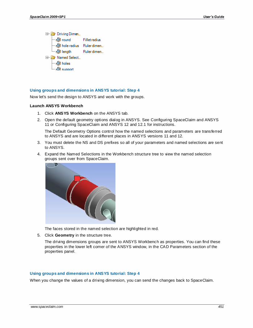
SpaceClaim 2009+SP1 User’s Guide
www.spaceclaim.com 451
Using groups and dimensions in ANSYS tutorial: Step 4
Now let's send the design to ANSYS and work with the groups.
Launch ANSYS Workbench
1. Click ANSYS Workbench on the ANSYS tab.
2. Open the default geometry options dialog in ANSYS. See Configuring SpaceClaim and ANSYS 11 or Configuring SpaceClaim and ANSYS 12 and 12.1 for instructions.
The Default Geometry Options control how the named selections and parameters are transferred to ANSYS and are located in different places in ANSYS versions 11 and 12.
3. You must delete the NS and DS prefixes so all of your parameters and named selections are sent
to ANSYS.
4. Expand the Named Selections in the Workbench structure tree to view the named selection groups sent over from SpaceClaim.
The faces stored in the named selection are highlighted in red.
5. Click Geometry in the structure tree.
The driving dimensions groups are sent to ANSYS Workbench as properties. You can find these
properties in the lower left corner of the ANSYS window, in the CAD Parameters section of the properties panel.
Using groups and dimensions in ANSYS tutorial: Step 4
When you change the values of a driving dimension, you can send the changes back to SpaceClaim.

SpaceClaim 2009+SP1 User’s Guide
www.spaceclaim.com 452
Change a driving dimension
1. Change the values of the following CAD parameters:
round from 1 to 2
hole radius from 1.4 to 1
length from 35 to 38
In ANSYS 11, change the values directly in the properties panel.
In ANSYS 12, click each parameter you want to drive. A letter P should appear next to each parameter. Go back to Workbench and edit the parameter values using the parameter group that appears in a new cell.
2. Send the changes back to SpaceClaim by clicking Update: Use Simulation Parameter Values.
This will change the model in ANSYS and in SpaceClaim.
Before: After:
Also notice that when you click on the groups in the Groups panel, you see the dimensions specified in ANSYS.
Using groups and dimensions in ANSYS tutorial: Step 5
You can also use annotation dimensions to drive changes in ANSYS.
Driving changes with annotation dimensions
1. In SpaceClaim, click the box next to the annotation plane so it is visible.

SpaceClaim 2009+SP1 User’s Guide
www.spaceclaim.com 453
2. Click Move in the Edit group on the Design tab.
3. Select Inner_tube_pushed_in_position in the Structure tree.
4. Click the red axis of the move handle:
You must select an axis on the Move handle before you can use the dimensions to drive changes. Clicking a handle tells the Move tool which direction the change will be made. The sparks appear
only after an axis is selected.
5. Click the spark next to the 38mm dimension and change it to 40:

SpaceClaim 2009+SP1 User’s Guide
www.spaceclaim.com 454
6. Click Create Group in the Groups panel.
A new driving dimension is created from the annotation dimension and Move tool. Changing this
driving dimension is like using the Move tool to change the dimension.
7. Go back to ANSYS and click Update: Use Geometry Parameter Value .
The model will update and the new parameter will be passed over. Now you can change the
length of the model by changing the location of the part or by stretching the model.
Using groups and dimensions in ANSYS tutorial: Conclusion
In this tutorial, you have learned
Parameters and named selections can be passed into ANSYS by creating them in the Groups panel.
Driving dimensions are created when there is s dimension on screen or a dimension in the properties panel.
Parameters can be edited in ANSYS which will change the geometry in ANSYS and also change the
geometry in SpaceClaim.
SpaceClaim parts and properties in ANSYS
Workbench applications only support flat (single-level) assemblies. An ANSYS part is created for each
SpaceClaim part, at any level in the assembly. This part contains bodies that are visible and match the user import filters set in ANSYS. The filters are Import Solid Bodies, Import Surface Bodies, and Import Line Bodies.
In ANSYS Design Modeler, multi-bodied parts are parts (components) that contain more than one body (solid, surface, or line body). For example, for two surface or two solids to share topology, they must be placed in a multi-bodied part.
ANSYS Mechanical allows a maximum of two assembly levels. You can have components inside components, but nothing deeper.

SpaceClaim 2009+SP1 User’s Guide
www.spaceclaim.com 455
If you send a component with two or more bodies into ANSYS Mechanical, then it shows up as a part with multiple bodies in it (multi-bodied part).
If you send a component with two or more bodies into ANSYS Design Modeler, then everything becomes flat.
When you send a SpaceClaim assembly to ANSYS mechanical, it also gets flattened to 2 levels.
SpaceClaim:
ANSYS Mechanical:
ANSYS Design Modeler:
SpaceClaim part and body names in ANSYS
In Simulation, the Geometry node represents the assembly, and nodes immediately beneath that
represent parts. If a part has more than one body, then child nodes are shown for each body, but if there is only one body, no child nodes are shown. This is based on the number of bodies transferred, which is subject to visibility and filters.
For a multi-body part ANSYS Mechanical displays the part name on the part node and the body name on the body node, but for a single-body part ANSYS displays a combined name on the part node, in the form <Part name> (<body name>). For example, Wheel (Solid).
The image above shows an assembly in SpaceClaim on the left and the same assembly in ANSYS on the right. Component 1 is displayed as a single-body part in ANSYS and component 3 is moved to the root level.
Component instance names are not transferred.
Mass properties
ANSYS will calculate the volume, center of gravity, and moments of inertia of the part if these values are not supplied. SpaceClaim supplies the volume and allows ANSYS to calculate the center of gravity and
moment of inertia.
Using groups to drive changes in ANSYS
SpaceClaim and ANSYS have full round-t rip associativity. This means that changes to the model can be
sent back and forth between SpaceClaim and ANSYS.

SpaceClaim 2009+SP1 User’s Guide
www.spaceclaim.com 456
You can define groups to use as parameters and named selections. If the objects in the group are similar or related, then a property is created that can be used to change a parameter in ANSYS. For example,
you could create a group of all faces that have the same offset and use this group to change the offset in ANSYS.
See Using groups and dimensions in ANSYS tutorial for hands-on examples.
Using driving dimensions in ANSYS
You can create driving dimension groups in SpaceClaim and use them to change key dimensions in ANSYS. Just click on the part in the structure tree in ANSYS and find the CAD Parameters section in the Details panel. Change a value and run the analysis again to see its affect. You can use Update to send
the new values back to SpaceClaim.
Creating a driving dimension with Pull (offset)
Creating a driving dimension with Move (translation or rotation)
Creating a driving dimension with the Select tool (round radius and distance between offset faces)
Using named selections in ANSYS
You can create named selections in the SpaceClaim Groups panel and then use these groups as named selections in ANSYS.
See Using groups to drive changes in ANSYS for information about using groups to make changes to the design in ANSYS.
To create a named selection
1. Select the objects you want to include in the group.
You can use the Selection panel to select objects in the same part that are similar or related to the object that is currently selected.
2. Click Create Group in the Groups panel.
3. (Optional) Rename the group.
It is helpful to rename the groups with a prefix that tells you the group's type, because named selections and driving dimensions are grouped together in the structure in ANSYS.
4. Send the design to ANSYS.
Shared topology in ANSYS
SpaceClaim can share topology (face, edge, and vertex connections) between touching or intersecting
bodies in designs that are transferred to ANSYS.
Shared topology is the only way to achieve a conformal mesh where bodies meet, and is the only way to be certain that the intersection of bodies is meshed perfectly.
In order for solids, surfaces, and beams to share topology, they must be placed in the same component in SpaceClaim and that component must have its Share Topology property set to true. A component that contains two or more bodies is called a multi-bodied part.
For ANSYS 12.0 and 12.1, if a part has the Shared Topology property set to true, then that part and all parts beneath it become a share group. Flags lower in the structure are ignored, so you can't use them to create sharing exceptions. For example, if you set Shared Topology to true for the root part, then the
entire model will be one share group. The name of the part node is the name of the part from which recursive sharing starts. The bodies under this node are listed with full path names through the assembly, such as Axle Sub-Assy (Front)\Wheel (Left)\Solid, using component names in parentheses if
they are present.

SpaceClaim 2009+SP1 User’s Guide
www.spaceclaim.com 457
See the Shared topology tutorial for hands-on experience with shared topology. See ANSYS online help for detailed information about how ANSYS handles multi-body parts and shared topology.
To use shared topology in ANSYS
Put the bodies in the same component and set the Shared Topology property on the component to True.
This property can be found in the properties panel when you select one or more components in the Structure tree.
To prevent shared topology in ANSYS
Place solids in their own components or set the component's Shared Topology property to False.
Examples
ANSYS meshes two parts with shared topology because they are in the same component. The blue block will gain a new imprinted face which will be shared between the green and blue blocks. Notice how the
nodes of the mesh line up along the bottom of the smaller block.
ANSYS creates separate meshes for two parts because they are in different components.
The mesh for shared topology is not the same as merged geometry. Here the boxes are merged, and you
can see that the mesh is different than it is for two bodies with shared topology.
ANSYS Workbench settings
There are many user preferences in Workbench that control geometry transfer. The settings supported by
SpaceClaim are explained below.
Workbench setting Description
Parameter Processing The following parameters are transferred:
Part parameters: Only includes the sheet metal parameters for thickness, inner radius, and kFactor if the part is a sheet metal part. These are transferred with the names, Sheet.Thickness,
Sheet.InnerRadius, and Sheet.kFactor.
Assembly parameters: Groups for the active window (belonging to the root part) that have a dimension.

SpaceClaim 2009+SP1 User’s Guide
www.spaceclaim.com 458
If you have more than one part occurrence for the same part master in
SpaceClaim (for example, 4 wheels in a car assembly), then part parameters are only transferred for the first occurrence. We do not transfer the parameters for each part node because Simulation allows you to set
contradictory parameters on different nodes, even if they share the same geometry.
The Parameter Processing option also controls whether parameters are
applied if they have been changed in Simulation and then the Update: Use Simulation Parameter Values command has been executed.
New assembly parameters are applied in the order that dimension groups
are listed in the Groups panel in SpaceClaim. You can change this order by dragging a group to a new location in the list.
Personal Parameter Key The Personal Parameter Key is a string that can match the start or the end of the parameter name. You can specify more than one key separated
by semicolons. By default, SpaceClaim groups have no parameter prefixes.
Named Selection Processing
Named selections for the active window (belonging to the root part) are transferred, if their members are bodies, faces, or edges. We SpaceClaim does not transfer vertex members, since we cannot does not support CAD
Associativity for vertices, because they don't have persistent identifiers in SpaceClaim.
Named Selection Prefixes Supported by SpaceClaim.
Materials Property Transfer
Supported by SpaceClaim.
CAD Associativity This option may slow things down, which is why there is a preference to turn it off. With SpaceClaim, the performance difference should be
negligible, so you should keep it enabled.
Import Coordinate Systems
Coordinate systems belonging to the root part are transferred.
Import Using Instances Simulation allows parts to share a brep, which means transfer is faster and the brep only needs to be meshed once. Because spot weld points must be defined in terms of special vertices created in the brep (for example, a
vertex in a face requires a degenerate loop containing a single vertex), breps can only be shared if they are identical in the spot welds that they have. SpaceClaim compares spot weld points and create instances that
share a brep for those part occurrences that have the same spot weld requirements.
We recommend that you leave this option turned on.
Do Smart Update Smart update will only re-transfer parts that have changed, which can save
a lot of time with a large assembly. Unfortunately, what constitutes a change in this case is an all-or-nothing consideration, which means a part will need to be re-transferred, along with any other parts that would
share its brep, if any of the following have changed:

SpaceClaim 2009+SP1 User’s Guide
www.spaceclaim.com 459
The placement of the part occurrence in the overall assembly has
changed.
Bodies have changed geometry, or been added/removed, or been made visible/invisible, or the user filters have selected different bodies.
The name of the part or any of the bodies has changed.
Named selection members for this part occurrence have changed.
Spot weld points for this part occurrence have changed.
Parameters (currently only sheet metal parameters) for this part have changed.
If you save your work in Simulation as a "dsdb" file, the timestamps used for smart update are saved with it, which means smart update continues to work in the next session.
Attach File Via Temp File Attach is what ANSYS calls a transfer. This preference uses a file for data
transfer rather than reading data streams directly. This may be faster for large assemblies.
Analysis Type If this is set to 2D, then only surface bodies lying in the XY plane are transferred.
Mixed Import Resolution Simulation does not support bodies of mixed dimensionality in a multi -body
part. They will transfer successfully, but they will fail to mesh. Mixtures of surface and line bodies are supported, but mixtures of solid -surface or solid-line are not. Therefore, if a part contains a mixture of solid and
surface bodies, which is quite common in SpaceClaim, Mixed Import Resolution can be used to specify whether solids bodies or surface bodies should be used.
If Mixed Import Resolution is set to None, a mixture of solid bodies and surface bodies could be transferred, and as already mentioned, the part will fail to mesh. The default setting is None, since most CAD systems do
not support mixtures of solids and surface bodies, but this setting should be set to Solid or Surface with SpaceClaim.
Settings not supported by SpaceClaim
The following settings are not supported by SpaceClaim:
CAD Attribute Transfer
Reader Save Part File
Enclosure and Symmetry Processing
Work points (construction points)
Configuring SpaceClaim and ANSYS 12 and 12.1
To set the add-in transfer options in SpaceClaim
1. Click in the lower right corner of the ANSYS 12 group on the Prepare tab.
The Options dialog opens.

SpaceClaim 2009+SP1 User’s Guide
www.spaceclaim.com 460
2. Select the following options:
Use tolerant stitching: Stitch the edges of nearby surfaces together when they are sent
to Workbench. Set the tolerance value to control the maximum size of the gap between edges that will be made into a single connected edge. A larger tolerance value will be more aggressive in stitching nearby edges together.
3. Click OK.
To set the Workbench geometry import options
In order to transfer geometry, parameters, and named selections from SpaceClaim to ANSYS Workbench, the correct import options must be set within Workbench. To set the import options in ANSYS Workbench,
1. Click Tools > Options in the ANSYS Workbench menu.
2. Click Geometry Import in the left panel of the Options dialog.
3. Select 3D for the Analysis Type.
4. Make sure there are no prefix values to filter for in the Parameters or Named Selections fields.
5. The following options should not be selected: Reader Save Part File, and Smart Update.
All other options should be selected.
6. Select None for Mixed Import Resolution.
7. Restart Workbench for the changes to take effect.
Connecting to ANSYS 12 and 12.1
To launch Workbench from SpaceClaim
If you have the ANSYS add-in installed in SpaceClaim and ANSYS installed on your computer, then you will see a new ANSYS 12 group on the Prepare tab. Click the ANSYS Workbench button to send the current model in SpaceClaim to a new project in Workbench.
To connect to SpaceClaim from ANSYS Workbench
Right -click on a geometry cell in ANSYS Workbench and select an active SpaceClaim document or browse for a saved document.
After you select a SpaceClaim document to attach to, the geometry cell will display a SpaceClaim icon.
Updating data with ANSYS 12 and 12.1
When you transfer geometry to ANSYS, only surface bodies are stitched. Other bodies are fused, and a warning is issued if shared topology fails
To send updates from ANSYS Workbench to SpaceClaim
Right -click a geometry cell and select:
Update to send parameters that have been modified in Workbench to SpaceClaim.
This step sends parameters that have been modified in Workbench to SpaceClaim. SpaceClaim makes the modifications to the geometry using the values of the new parameters and sends the
resulting model back to Workbench.
Update From CAD to send the current version of the model in SpaceClaim to Workbench.
This step sends the current version of the model in SpaceClaim to Workbench so the data is up-to-
date in both.

SpaceClaim 2009+SP1 User’s Guide
www.spaceclaim.com 461
To send updates from ANSYS Mechanical to SpaceClaim
When a model is loaded into ANSYS Mechanical (the simulation environment), changes made to the model in SpaceClaim can be passed into the simulation at any time.
1. Right -click the geometry node in the Project tree in ANSYS Mechanical.
2. Select Refresh Geometry.
The current version of the model in SpaceClaim will be transferred into the simulation.
Configuring SpaceClaim and ANSYS 11
To set the add-in transfer options in SpaceClaim
1. Click in the lower right corner of the ANSYS 11 group on the Prepare tab.
The Options dialog opens.
2. Select the following options:
Use tolerant stitching: Stitch the edges of nearby surfaces together when they are sent to Workbench. Set the tolerance value to control the maximum size of the gap between edges that will be made into a single connected edge. A larger tolerance value will be
more aggressive in stitching nearby edges together.
3. Click OK.
To set the Workbench geometry import options
In order to transfer geometry, parameters, and named selections from SpaceClaim to ANSYS Workbench,
the correct import options must be set within Workbench. You can find these options in the Options panel on the left side of the Workbench window.
To set the default import options,
1. Click Tools > Options in the ANSYS Workbench menu.
2. Enable Parameters and Named selections and delete the prefix values in the fields to the right of these options.
Connecting to ANSYS 11
To launch Workbench from SpaceClaim
If you have the ANSYS add-in installed in SpaceClaim and ANSYS installed on your computer, then you will see a new ANSYS 11 group on the Prepare tab. Click the ANSYS Workbench button to send the
current model in SpaceClaim to a new project in Workbench.
To connect to SpaceClaim from ANSYS Workbench
In the Link to Geometry File section, click Browse and locate the SCDOC file. This attaches the SpaceClaim design to the workbench project.
Updating data with ANSYS 11
When you transfer geometry to ANSYS, only surface bodies are stitched. Other bodies are fused, and a warning is issued if shared topology fails
To send updates from ANSYS Workbench to SpaceClaim
Right -click a geometry cell and select:

SpaceClaim 2009+SP1 User’s Guide
www.spaceclaim.com 462
Update to send parameters that have been modified in Workbench to SpaceClaim.
This step sends parameters that have been modified in Workbench to SpaceClaim. SpaceClaim
makes the modifications to the geometry using the values of the new parameters and sends the resulting model back to Workbench.
Update From CAD to send the current version of the model in SpaceClaim to Workbench.
This step sends the current version of the model in SpaceClaim to Workbench so the data is up-to-
date in both.
To send updates from ANSYS Mechanical to SpaceClaim
Update: Use Simulation Parameter Values to send parameter changes from Workbench to SpaceClaim.
Update: Use Geometry Parameter Values to send the current version of the model in SpaceClaim to Workbench.

SpaceClaim 2009+SP1 User’s Guide
www.spaceclaim.com 463
Glossary
3
3D markup
SpaceClaim document that enables you to annotate and compare different versions of a design.
A
Absolute coordinates
See Coordinates
ACIS
Modeling engine by Spatial Corporation. SpaceClaim can import and export ACIS files (.sat and .sab).
Alignment axis
Axis around which you can rotate a component using the Orient tool.
Anchor
Move tool - The center ball of the Move handle. You can drag the center ball or use the Anchor tool guide to place the anchor on a solid, face, edge, vertex, or origin.
Patterns - A member of a linear or rotational pattern that does not move with the pattern. You can anchor one or more pattern members using the Fulcrum tool guide.
Detail view - A point used as the starting point for scaling.
Anchor point
See Anchor
Angular reference
Starting point for dimensioning an angle.
Angular ruler dimension
See Ruler dimensions
Annotation
Information you can add to a drawing, such as notes, dimensions, geometric tolerances, center marks, and Bills of Materials.
Annotation plane
Plane on which you can annotate designs, drawing sheets, and 3D markups. Use the Create Note tool to select an annotation plane and enter text onto the plane.
Arc
Curved line of constant radius; part of a circle.
See Sweep arc, Three point arc, Tangent arc
ASME
American Society of Mechanical Engineers standards for engineering drawing practices. You can customize the style of your annotations to conform to ASME standards.
See ISO, JIS
Aspect ratio
Ratio of the length to width of a rectangle or the height to width of an image. When resizing images, it can be important to maintain the aspect ratio to avoid distortion.
Assembly
Hierarchy of components and subcomponents showing relationship within a design, as shown in the Structure tree. In manufacturing, a unit fitted together from manufactured parts.
See Assembly tool, Component
Assembly tool

SpaceClaim 2009+SP1 User’s Guide
www.spaceclaim.com 464
Use the Assembly tools to specify how components are aligned with each other, that is, create a mating condition. You can Align, Center, and Orient components.
Association
Relationship between objects that enables you to edit them together. For example, when you pull a polygon into 3D, the faces acquire a polygon relationship. If you act on one face or edge, it affects all the faces in the polygon. Another example of an association is a mirror plane between two faces.
See Mirror, Remove associations
AutoCAD
Software application for 2D and 3D design and drafting by Autodesk, Inc. AutoCAD's native file format is DWG, its interchange file format is DXF, and its format for publishing CAD data is DWF.
Axial face
Face of a 3D object through which an axis extends. The axis displays when you move the cursor over the axial face.
Axis
Straight line that an object rotates around or that objects are regularly arranged around.
See Alignment axis
B
Balloon
Annotation consisting of content from the Bill of Materials. Balloon notes update when changes are made to the BOM table.
Baseline faces
See Offset baseline faces
Bend allowance
Amount of material added to compensate for changes caused by bending sheet metal. Allowance is required to correct for the change in length caused by bending a flat sheet.
Bend deduction
Value used to calculate unfolded lengths of sheet metal. Bend Deduction is twice the distance from the outside mold line to the beginning of the bend (set back) minus the bend allowance.
Bend deduction table
CSV (comma-separated value) file used to calculate the developed lengths for unfolded or flat patterns to be machined.
Bill of Materials (BOM)
Table of components, sub-components, parts, and materials needed to manufacture a finished product.
Blend
Smooth and tangent transition between faces or edges; created using the Pull tool.
Blend plane
Sections that appears when you edit a face as a blend using the Edit as Blend tool. You can create, move, and orient blend planes.
Blend surface
Faces you can edit using the Edit as Blend tool. If the face was originally created as a blend, the original blend surfaces are available for editing. If the face is not blended, the tool first converts the face to a blended surface.
Blended face
Face created by blending between two edges.
Body
A solid or surface.
Bounded line
Segment of a line bounded by one of more intersections with lines or edges. Use the Trim Away tool to delete a bounded line.

SpaceClaim 2009+SP1 User’s Guide
www.spaceclaim.com 465
C
CATIA
Modeling engine by Dassault Systèmes. SpaceClaim can import and export CATIA files.
Chamfer
Sloping corner between two edges created using the Pull tool; angle with equal setback; bevel.
Chord
Straight line with both end points on a circle.
Chord angle
Degrees of a circle delineated by a chord. In a Swept arc, the starting point and end point of the arc define the chord.
Clip
Hide all geometry in a design above or below the grid or selected plane.
Closed lines
Intersecting lines that enclose an area to form a region when you sketch shapes in 2D. The regions will become solids and the lines become edges when you pull your sketch into 3D.
Closed loop
Contiguous sketched lines or edges. Can be selected by double-clicking one of the edges or lines.
Coaxial
Relationship between faces that share the same center of rotation. If you check the Coaxial Face Groups box in the Display tab, faces that share an axis are indicated with blue shading.
Combine
SpaceClaim tool used to cut or glue geometry together.
Component
Object in a design, including the top-level design component. Each component consists of any number of objects, such as solids and surfaces, and can contain sub-components. You can think of a component as a "part."
Components can be saved as a separate file. An external component is another design inserted as a component of your design. Making the component independent prevents changes from being made to the external component file. You can also create an external component by saving a component as a separate file.
See Lightweight components, Assembly
Constant-radius round
Default configuration for a fillet. The radius of the rounded corner is uniform across the length of the line or edge.
See Fillet, Variable radius round
Construction circle
Shape drawn with a Sketch tool to help you create an accurate sketch, for example, of objects in a circular relationship around a center (bolt holes in a flange). Construction circles cannot be pulled into 3D and are removed when you exit sketching mode.
Construction line
Shape drawn with a Sketch tool to help you create an accurate sketch. Construction lines become axes in 3D. They are also useful for creating mirrors.
Context menu
In the SpaceClaim user interface, a list of functions specific to the operation that you are performing. Access the context menu by right-clicking in the design window.
Converging lines
Non-parallel lines. With the Dimension tool, you can annotate converging lines at a virtual sharp.
Coordinates
Method of inputting points based on distance and angle.
Absolute coordinates are measured from the origin (x and y for 2D and x, y, z for 3D).

SpaceClaim 2009+SP1 User’s Guide
www.spaceclaim.com 466
Relative coordinates are measured from the selected point (x and y for 2D and x, y, z for 3D).
Polar coordinates are measured by entering values for distance and angle.
Corner
See Fillet (interior corner) or Round (exterior corner)
Cross-section mode
Mode used to edit solids by working with their edges and vertices in cross-section. In this mode, pulling a line pulls a face, and pulling a vertex pulls an edge.
To create a cross-section view, you select the face that will be used to set the cross-section plane. Hatching is used to show the intersection of the cross-section plane and a solid.
Cross-section view
One of the view selections for drawing sheets. Cross-section view shows a cross-section through your design. You create a cross-section view from one of the other views on the drawing sheet.
See General view, Projected view, and Detail view
Curvature
Analysis tool that displays a fringe graph or color shading to represent the curvature along curves or edges. Values indicate how curvy or "swoopy" the curve or surface is at each point.
Curve
In 3D, any line in space.
Curve center
A small cross that appears on the sketch grid at the center of a circle, ellipse, polygon, or arc.
Curved slot
A slot created by pulling a hole along the axis of a driving cylinder. A 360 degree curved slot is a round cut.
See Radial slot
Cutter object
When using the Combine tool to split a solid or surface, the Cutter object is the solid or surface you use to cut the target. Use the Select Cutter tool guide to select the Cutter object.
Cylindrical face
The surface of a cylinder, formed by points at a fixed distance from the axis of the cylinder.
D
Datum
Object that is assumed to be an exact size and shape, and be in an exact location, that is used to locate or establish geometric relationship of other objects.
Datum symbol
Symbol attached to a point, axis, or plane that must be referenced for machining and inspection.
Design
2D or 3D model that contains at least one top-level component.
Design component
See component
Design window
Area in SpaceClaim user interface displaying your model or assembly. Also known as Workspace.
Detach
Create separate surfaces from individual pieces of a sketch, or objects or faces in 3D. You can detach protrusions to move them with the Move tool's Detach First option.
Detail
Aspects of a design incorporated to communicate with others or submit the design for review. Use the tools on the Detailing tab to annotate designs, create drawing sheets, and review design changes. You can customize detailing settings to conform to standards or create your own custom style.

SpaceClaim 2009+SP1 User’s Guide
www.spaceclaim.com 467
Detail view
One of the view selections for drawing sheets. Detail view creates an enlarged view of a particular area, magnifying a portion to show more detail. You create a detailed view from one of the other views on the drawing sheet.
See General view, Projected view, and Cross-section view
Dimension
Annotation on a drawing showing measurement of an edge or face. Use the Dimension tool to add measurements to your design, drawing sheet, or 3D markup.
Dimensional sketching
Precise sketching by entering measurement values for the current line or relative to other lines and points.
See Dimensions
Dimensions
Values or expressions you enter for precise control during the creation or modification of a design. You can dimension every element, from lines in sketches to faces of solids.
See Ordinate dimensions, Progressive dimensions, Ruler dimension
Document
A SpaceClaim file (.scdoc) that may contain any combination of design versions, associated drawing sheets, and 3D markup slides.
Draft
Angle or taper on an object that facilitates removal from a mold or die. You draft by pulling one or more faces around about another face that you selected as the pivot. You can add or cut material as you pull.
Draft faces
See Draft
Driving cylinder
Shape used when pulling a hole to create a curved or radial slot. You select the face or axis of the driving cylinder to guide the shape of the slot.
Driving edge
Edge you select to drive the change when using the Pull tool. Select a driving edge for revolves, directed extrusions, sweeps, and drafts. The driving edge is shown in blue.
Driving face
Face you select to drive the change when using the Pull tool. Select a driving face for revolves, directed extrusions, sweeps, and drafts. The driving face is shown in blue.
DWG
AutoCAD native drawing format. SpaceClaim can open and insert drawings, parts, and assemblies. Drawings can be inserted as layouts. SpaceClaim can export parts, assemblies, drawing sheets, and 3D markup slides.
DXF
Drawing Interchange Format or Drawing Exchange Format. CAD data file format developed by Autodesk for enabling data interoperability between AutoCAD and other programs.
SpaceClaim can open and insert drawings, parts, and assemblies. Drawings can be inserted as layouts. SpaceClaim can export parts, assemblies, drawing sheets, and 3D markup slides.
E
Eccentric
Not sharing the same center.
Edge
3D object composed of a single outside boundary of a feature. A line sketched in 2D becomes an edge when you pull your sketch into 3D.
Edge chain
Tangent chain; a continual series of edges that are connected edge-to-edge. Double-clicking an edge in the chain selects the entire chain.

SpaceClaim 2009+SP1 User’s Guide
www.spaceclaim.com 468
Edge loop
All of the edges around a face; a continual series of edges that are connected edge-to-edge forming a closed loop. Double-clicking an edge in the loop selects the entire loop.
Edge tangency
When you blend between two faces, the blend surface begins tangent to the edges of the initial faces and ends tangent to the edges of the end faces. By deciding which edges you do not want to use for tangency, you can create a blend with or without the effects of the edges.
Edit faces as a blend
Using the Edit as Blend tool to move or orient blend planes to edit a face as a blend.
See Blend plane, Blend surface
Ellipse
Geometric shape described as a circle viewed at an angle; oval with two centers of equal radius.
Entity
Term used to refer to any object in a 2D sketch or 3D drawing.
Exploded assembly
View of components in which objects are shown along an axis line.
Extents
The outer boundaries of the objects you have drawn.
Extrude
To pull a face along with its edges. The edges extend to bound the extruded face, creating a new section defined by the edges.
F
Face
Side or other surface of a solid. Some examples are the inside surface of a hole or the six sides of a rectangular solid.
See Surface
Face grid
Horizontal and vertical lines, displayed using the Face Grid tool, that define any face or surface you select in your design.
Face styles
Modes you can select for displaying a solid or surface. You can set the display to be transparent, opaque, or metallic.
See Graphics styles
Fade scene
Make the geometry under the sketch grid more transparent, by selecting Fade Scene Under Grid in SpaceClaim options. Selecting this option enhances the visibility of your sketch.
Fill
Use the Fill tool to simplify or clean up geometry by extending surrounding faces to eliminate a selection. The selected region is filled in or healed with the surrounding surface or solid.
Fillet
Rounded corner at the intersection of two lines or edges; concave intersection between two surfaces. Fillet refers to an interior corner; exterior corner is known as a round. You can draw a fillet using the Create Rounded Corner tool or by selecting the Fillet (Constant radius round) option from the Pull options.
See Round
Filleted corner
See Fillet
Filter

SpaceClaim 2009+SP1 User’s Guide
www.spaceclaim.com 469
See Selection filter
Flag note
See Note
Fulcrum
Hinge; pivot point. When using the Move tool, you can select an object and use the Fulcrum tool guide to move other objects around it.
Full pull
Pull tool option that enables you to revolve 360 degrees or to the next face, sweep through the full trajectory, or blend through selected faces.
G
General view
One of the view selections for drawing sheets. General view makes the selected view independent of the view used to create it.
See Projected view, Cross-section view, and Detail view
Geometric tolerances
Annotation symbols used for dimensioning geometry in technical drawings; usage is guided by ASME, ISO, and other standards.
Golden rectangle
A rectangle with ratio of side lengths (approximately 1:1.618) considered by artists and architects to be aesthetically pleasing. As you sketch a rectangle, an indicator line appears when the shape has the proportions of a square or golden rectangle.
Graphics styles
Modes you can select for displaying a design. You can display geometry as shaded, perspective shaded, wireframe, wireframe with hidden lines displayed in light gray, and wireframe with hidden lines removed. You can apply styles to your entire design or drawing sheet, to individual layers, or to individual views in your drawing sheet.
See Face styles
Grid
See Sketch grid
Grid lines
See Face grid
Groups
Sets of objects that appear in the Groups tab. You create a group from any set of selected objects. Information such as Selection, Alt+selection, move anchoring, axis, and ruler dimension is all stored with the group.
GTOL
See Geometric tolerance
Guides
See Tool guides
H
Heal
See Fill
Helix
Pull tool option that revolves the selected shape around an axis to create a screw or drill shape. You control the height, direction, pitch, and taper.
Home view
Tool used to return the view to the Home settings. You can customize the Home view tool so that it displays your design with a specific orientation, location, and zoom level.

SpaceClaim 2009+SP1 User’s Guide
www.spaceclaim.com 470
I
Imprinted edge
A line that does not define a corner. For example, you might create an imprinted edge on a face of a cube, if you want to divide the face and pull different parts. Imprinted edges are often created when importing designs.
Inking a line
See Project to sketch
Interference
Edges where solids intersect each other or volumes created by the intersection of solids, surfaces, and components in your design; can be displayed using the Analysis tools.
Intersect
SpaceClaim tool used to split solids and faces.
Inverse selection
The inverse of the current selection in the active component. For example, if you select the top face of a cylinder, right-click and select Select > Inverse Selection, the entire cylinder except the top face will be selected.
ISO
International Organization for Standardization standards for architectural and engineering drawing, including guidelines for dimensioning and tolerancing. You can customize the style of your annotations to conform to ISO standards.
See ASME, JIS
Isometric view
3D view of surfaces and edges, oriented to show the top, front, and side faces of your design. The angles between the projection of the x, y, and z axes are all equal at 120°.
See Trimetric view
J
JIS
Japanese Standards Association standards for technical drawings. You can customize the style of your annotations to conform to JIS standards. JIS defaults are the same as ISO, except that JIS uses third-angle views while ISO uses first-angle views.
See ASME, ISO
K
K-factor
Parameter of bends in a sheet metal part used to calculate the bend radius. K-factor is a percentage of the metal thickness and depends on factors such as the material and type of bending operation.
Relates to the depth of the neutral axis; a line within the sheet where the length does not change when the sheet is bent. The inside of the bend is under compression, the outside is under tension, and the neutral axis occurs somewhere between the midpoint of the material (K-factor=0.50) and a point closer to the inside of the bend (K-factor=0.25).
L
Layer
Grouping mechanism for visual characteristics such as visibility and color. You can group objects on layers to organize your drawing. Layers are especially useful when you want to show or hide annotation planes.
Layout
2D drawing mode that is most useful when you have no immediate need to generate 3D objects from the lines in the layout. If you try to pull layout lines to 3D, they do not behave the same way that sketched lines do.
Think of a layout as a pencil drawing made on your design. When you are ready to use your layout to create geometry, you must project the layout lines to a sketch. Projecting a layout line to a sketch is like inking the line.
You can import a 2D AutoCAD DXF or DWG file as a layout.

SpaceClaim 2009+SP1 User’s Guide
www.spaceclaim.com 471
Library
Resource available for downloading from SpaceClaim options. Provides materials and properties selections in the Properties panel. You can select from the Materials Library and add them to your Local Materials.
Lightweight assembly
Graphics-only representation of a design. When inserting an external file into a design, select the Enable lightweight assemblies option to load only the component's graphic information. This improves performance of large and complex assemblies for quicker viewing. When you are ready to work with the component in SpaceClaim, you can load the geometry information.
Lightweight component
See Lightweight assembly
Line
A straight line, arc, or spline drawn in Sketch mode or on a layout plane. Lines have length but no area. When you pull a sketch into 3D with the Pull tool, lines become edges.
Local materials
See Library
M
Markup
Slides you can create to highlight and communicate the differences between versions of a design.
Mass
Analysis tool used to display mass properties, or volume information for the solids and surfaces in your design.
Mass properties
See Mass
Material
Property that you can assign to an object, consisting of material name and attributes such as density and tensile strength.
Materials library
See Library
Mating condition
Attribute of components that specifies how they are aligned with each other. You create mating conditions with the Assembly tools.
Measure
Tools for displaying measurement properties of the edges, faces, and solids in your design.
Mini-toolbar
Set of tool-specific options that appears when you right-click in the Design window. You can also access the options in the Options panel.
Mirror
Associative relationship between two faces or planes mirrored about a centerline plane or planar face. The second object is a copy of the original; if the geometry of the original is changed, the mirrored copy is also updated.
Use the Mirror tool to designate a face or plane as a mirror, or to create a mirror plane between two faces.
Mode
Three ways of designing in SpaceClaim: Sketch, Cross-section, or 3D. You can switch between modes at any time.
Mouse up
See Zoom box in
Move
SpaceClaim tool used to translate or rotate geometry.

SpaceClaim 2009+SP1 User’s Guide
www.spaceclaim.com 472
N
Neutral plane
Pull tool: the plane, face or edge around which you want to pivot.
Sheet metal: the line within a sheet where the length does not change when the sheet is bent; axis.
Non-planar edges
Edges that do not lie in the same plane.
See Planar edges
Normal
The vector that is perpendicular to a flat plane at the selected point. In the case of a non-flat plane, the vector that is perpendicular to the plane tangent to the surface at the selected point.
Note
Annotation placed on a design, drawing sheet, or 3D markup. Notes contain text or symbols that you insert and can be connected to geometry by a note leader.
O
Object
Anything recognizable by SpaceClaim tools. 3D objects include vertices, edges, faces, surfaces, solids, layouts, planes, axes, and origins. 2D objects include points and lines.
Offset
Distance an edge, segment, or curve is moved or copied.
Offset baseline faces
See Offset relationship
Offset relationship
A relationship between two faces that is maintained in the 2D and 3D editing tools.
Offset relationships are created when you
Define a relationship using the Offset tool.
Create a sheet metal part.
Shell a solid.
Offsetting faces
Pulling a face without selecting the edges. The pull extends the neighboring faces without creating an edge. The neighboring faces extend to bound the offset face, creating a new section defined by the adjacent geometry.
Offsetting lines
Using the Offset Line tool to create an offset of any line or spline in the grid plane. A new object is created at a specified distance from the selected object.
Options panel
Area of SpaceClaim user interface that enables you to modify functions specific to tools.
Ordinate dimensions
X or Y distances that originate from a single location, which is usually the lower left corner of the object. Also known as datum dimensioning or baseline dimensioning
Orientation angle
Property that you define when sketching a polygon. Orientation angle determines the polygon’s rotational position.
Origin
Zero point in coordinate system. You can insert an origin at any location in your design where you can anchor the Move tool, enabling you to dimension from the origin or quickly move the sketch grid to the origin. You can also insert an origin at a solid's center of mass or volume.
Origin Axis
Axis through the origin.
Orthogonal view

SpaceClaim 2009+SP1 User’s Guide
www.spaceclaim.com 473
Projection that is constrained to regular 90° angles (top, bottom, left, and right of the current view). When you create a projected view from one of the other views on the drawing sheet, the available projections are orthogonal (orthographic).
P
Pan
Move a drawing around by dragging the drawing area around your screen; move the viewpoint laterally relative to the drawing.
Panel
Sections of the SpaceClaim user interface that initially appear along the left side of the application window and include: Structure panel, Layers panel, Selection panel, Groups panel, Options panel, and Properties panel. You can dock and detach these panels.
Parasolid
Parasolid geometric modeling kernel. SpaceClaim can open and insert parts and assemblies and export parts and assemblies.
Parent component
A component upon which other components depend. For example, in a block with a hole, the block is the parent and the hole is the child.
Patch blend
Fill tool option that uses the initial tangency of the neighboring faces to fill the selected edges. Faces are blended into a smooth, single-face patch, instead of extending the faces attached to the edge until they intersect. Deselecting the Tangent extension option ignores the tangency of the neighboring faces.
Periodic blend
Pull tool option used to go all the way around when blending faces.
Pitch
Unit of length that a helix face shifts per 360º rotation; distance from one point on a thread to the corresponding point on the next thread.
Pivot line
Line around which a face is revolved using the Pull tool.
Plan view
Head-on view.
Planar edges
Two or more edges that lie in the same plane. You can select planar edges and select the Plane tool from the Insert ribbon group to insert the plane defined by the edges.
Planar face
Face that lies within a plane.
Plane
Construction geometry consisting of a flat surface. Planes can be used for a 2D sketch, section view of a model, a neutral plane in a draft feature.
PMI
Product Manufacturing Information. SpaceClaim can import PMI if you check the Import Part Manufacturing Information box when importing CATIA files.
Point
Single location in the sketch grid. 2-D object that has no height, width, or length. The origin, an axis, and a vertex are examples of points.
Use the Point tool to sketch a point on the sketch grid. Points are useful as a dimensional reference, for splitting, and for creating a point on a line or curve through which you want to draw a three-point circle.
Polar coordinates
See coordinates
Polygon

SpaceClaim 2009+SP1 User’s Guide
www.spaceclaim.com 474
Complex object composed of three or more straight lines in a closed figure. Use the Polygon tool to sketch a polygon with up to 32 sides.
Power selection
Advanced selection tool available from the Selection tab. Enables you to search for and select all objects with geometry similar to the currently selected object.
Profile
Line in space; outline of an object; used to describe objects when sweeping or blending.
Project to sketch
Tool used to convert 2D layout lines to a sketch so you can use the layout to create geometry.
Projected view
One of the view selections for drawing sheets. You create a projected view from one of the other views on the drawing sheet to show another side of the model.
See General view, Cross-section view, and Detail view
Properties panel
Area of SpaceClaim user interface that displays editable details about the selected object(s). This panel is initially displayed on the lower left side of the screen, but can be moved.
Pull
Tool used to distort or deform geometry. Use the Pull tool to offset, extrude, revolve, sweep, draft, and blend faces; or to round, chamfer, or extrude edges.
When converting a sketch to 3D, pulling a line creates a surface and pulling a surface creates a solid.
Q
Quality
SpaceClaim tools for detecting anomalies or discontinuities in surfaces.
Quick Access Toolbar
Tool icons that appear at the top of the SpaceClaim user interface, next to the Application menu, and include common Windows commands such as Open, Save, and Undo. In SpaceClaim Options, you can customize the toolbar so that it contains the file-related shortcuts you use most often.
R
Radial slot
A slot created by pulling a hole toward the axis of the driving cylinder.
See Curved slot
Radiused corner
See Fillet (interior corner) or Round (exterior corner)
Reference line
Line used as the starting point for dimensioning.
Region
When you sketch shapes in 2D using the sketch tools, regions are formed by closed or intersecting lines. The regions will become solids and the lines become edges when you pull your sketch into 3D with the Pull tool.
Regular face
An unblended face. The face must be converted to a blended face before you can edit the face as a blend.
See Blend surface
Relative coordinates
See Coordinates
Remove associations
Tool that removes an associative relationship. For example, removing a polygon relationship enables you to make changes to only one face of the polygon solid without affecting the other faces.

SpaceClaim 2009+SP1 User’s Guide
www.spaceclaim.com 475
See Associations
Rendering
Mode available from the Properties panel for a view on a drawing sheet. Use Rendering mode to change the Graphics style for the view. Select Inherit if you want to link the graphics style to the parent view.
See Graphics styles
Revolve
Move in a path around an axis. Use the Pull tool to revolve faces, edges, or a helix around an axis. The axis may be a straight line, axis, or edge.
See Subtractive revolve
Revolve axis
A straight line, axis, or edge around which you revolve a face, edge, or helix.
Rotate
Design: Using the Rotate tool to spin a design 90 degrees in the plane of the screen. You can rotate your design clockwise or counterclockwise.
Object: Using the Move handle to spin an object around an axis.
Rotational blend
Pull tool option used when blending faces to create cylinders and cones whenever possible.
Round
Rounded corner at the intersection of two lines or edges. Round refers to an exterior corner; an interior corner is known as a fillet. In SpaceClaim, rounds and fillets are both called rounds.
See Fillet, Constant-radius round, Variable-radius round
Round Group
Grouping that is created each time you fill a round. You can reattach a group of rounds as long as some portion of the original edges (or faces that bordered the edges) still exists in your design.
See Group
Ruler dimension
Option used to enter precise dimensions when pulling or moving. Dimensions may be linear when moving or pulling, or angular when rotating.
S
Scale
Solid or surface: Change the size of the selected object using the Pull tool. You can scale dynamically or by entering a scale value.
Drawing sheet or cross-section views: Magnify or shrink the view by selecting a View in the Structure tree and editing the Properties panel.
SCDOC file
File format for SpaceClaim files (.scdoc). Files comply with the Microsoft Open Packaging Convention, which is also used by Microsoft Office 2007. These files are actually zip archives with a special structure, the contents of which are primarily XML data.
Section
Design mode in which you edit solids by working with their edges and vertices in cross-section. View is cut away to show interior detail.
Section mode
See Section
Selection filter
Drop-down control in the status bar that can be used to limit the selection of objects. Only object types you check will be selected; for example, only faces and edges.
Selection tab
Area of SpaceClaim user interface where you can locate objects similar to the ones selected.

SpaceClaim 2009+SP1 User’s Guide
www.spaceclaim.com 476
See Power selection
Shell
Solid or part that is hollowed out from a selected face, leaving a shell of designated thickness.
Shell relationship
Association that stays with a solid when it is moved to another component, unless the relationship would link two components when it is moved.
See Shell
Silhouette edge
Edge that is rotated to conceal a 3D object and appears as a 2D line.
Sketch grid
Pattern of regularly spaced lines that guides you when sketching. The sketch grid makes aligning and drawing objects easier.
You can adjust the units and spacing of the grid, as well as how solids are displayed when the grid appears.
Sketch mode
Mode for drawing in two dimensions using the sketching tools on the sketch grid. A sketch is a collection of lines and other 2D objects on a sketch grid.
Sketching creates regions that can be pulled into 3D. When you pull your sketch into 3D with the Pull tool, regions formed by intersecting lines will become solids and lines will become edges.
SLA
See Stereo lithography
Snap
Constrain to objects, angular and linear increments, or grid points while you are sketching or editing solids.
You can customize the snapping behavior in SpaceClaim options. Pressing Shift while dragging snaps the tool based on your snap settings.
You can use the Snap to grid tool to constrain or lock all drawing to grid points only.
Snap view
Tool used to display the head-on view of a face. You can also use the tool to "throw" the highlighted face to the top, bottom, right, or left.
Solid
Object that encloses volume. A surface becomes a solid if it encloses volume.
Spin
Tool used to re-orient your design in any direction, allowing you to view it from any angle.
Spin center
Axis about which you spin your design when you use the Spin tool.
Spline
A continuously curved line, without sharp boundaries (that is, without vertices). Create a spline by defining a set of points using the Spline tool. A spline becomes an edge when you pull it with the Pull tool.
Split
Using the Combine tool to split solids or surfaces. You select a solid or surface to use as a Cutting tool to cut the target.
See Cutter object
STEP
Standard for the Exchange of Product model data (ISO 10303). Defines a methodology for describing product data. You can select the STEP protocol to use to format exported SpaceClaim designs.
Stereo lithography
Technology used for rapid prototyping, in which a laser hardens successive layers of a photopolymer to create a part with a shape defined by a computer model.
STL file

SpaceClaim 2009+SP1 User’s Guide
www.spaceclaim.com 477
File format native to the stereo lithography CAD software created by 3D Systems. SpaceClaim can export parts and assemblies (.stl).See Stereo lithography.
Structure tree
Display in the Structure panel that shows you each of the objects in your design. You can expand or collapse the nodes of the tree to view the objects. You can rename objects, create, modify, replace, and delete objects, as well as work with components.
Subtractive
Manipulation (revolve, draft, pull, etc.) of a solid in which material is removed. In SpaceClaim, the cursor changes to - to indicate that the edit is subtractive.
Surface
Two dimensional object that has no thickness (as opposed to a face, which is part of a three -dimensional object). A surface has area but no volume.
See Face
Surface finish symbols
Annotation you can add to a drawing that provides instructions for material removal during manufacturing.
Sweep
Pull a surface or face along a line or edge using the Pull tool. You can sweep faces and edges, and select straight or curved lines or edges along which to sweep. Sweeping along a spline is a pulling technique for creating a smooth, swoopy shape.
See Trajectory
Sweep arc
Arc created by defining a center point and two end points; drawn using the Sweep Arc tool.
Sweep circle
The circular path followed by a Swept arc.
See Swept arc
Sweep trajectory
See Trajectory
Swept arc
See Sweep arc
T
Tangent
Line that touches a curve (arc or circle) at only one point, without crossing over, and is perpendicular to the radius at the point of tangency. In SpaceClaim, you can sketch a line tangent to a curve or you can sketch an arc tangent to a line or curve.
Tangent arc
Arc that is sketched using the Tangent Arc tool, using a point on a line or curve as the starting point.
Tangent chain
See Edge chain
Tangent edges
Transition edge between rounded or filleted faces in hidden lines visible or hidden lines removed modes in drawings.
Tangent extension
See Patch blend
Tangent faces
Faces created by rounds or when edges are drawn on a face.
Taper
Angle of a helix or threads made on a conical surface.

SpaceClaim 2009+SP1 User’s Guide
www.spaceclaim.com 478
See Helix, Thread
Target
The object you want to cut, when using the Combine tool to split a solid or surface.
Tessellation
An approach for data exchange between CAD programs. Tessellation represents entities such as lines and surfaces in a CAD system with tiny triangles (polygonal data representations). Data formats such as XML and VRML are examples of tessellated data.
Thread
Texture created on the surface of a cylinder, cone, or hole using the Annotation tools.
Three point arc
Arc created by defining a starting point, an end point, and a radius; drawn using the Three-Point Arc tool.
Tool guides
Functions that are specific to the selected tool.
Torus
Donut-shaped object created using the Pull tool to sweep a sketched shape around an axis on a circular path.
Trajectory
Straight or curved line or edge along which you sweep a face or an edge.
Translate
Move in a plane (x, y, or z).
Trim away
Delete a line portion bounded by an intersection with a line or edge.
Trimetric view
3D view of surfaces and edges, oriented to show the top, front, and side faces of your design. Compared to isometric view, trimetric view angles the front face slightly towards you, shows less of the side face, and less of the top. In SpaceClaim, this is the default Home view.
See Isometric view
U
UV grid
See Face Grid
U-V lines
See Face Grid
V
Variable radius round
Fillet created from a constant-radius round by selecting one edge of the round and pulling it to a new radius.
See Fillet, Constant-radius round
Vee die width
Sheet metal property; sets the width of the tooling that produces a bend.
Vertex
Point that terminates a line; point at which two or more lines or edges intersect. Vertices can be selected for sketching, dimensioning, and other operations.
View
Orientation settings that you can apply to your design, including spin, pan, and zoom. You can adjust these settings individually or you can apply one of the following preconfigured views: Trimetric, Isometric, Top, Bottom, Front, Back, Right, Left. You can also select Snap View and click a face to view it head-on.

SpaceClaim 2009+ User’s Guide
© Copyright 2009 SpaceClai m Corporation. SpaceClaim and the SpaceClai m logo are trademar ks of SpaceClaim Corpor ation. All other names mentioned herei n are either
trademar ks or registered trademarks of their respec tive owners.
Virtual sharp
Point of intersection formed by extending converging lines.
W
Wireframe
View mode in which all edges of the part or assembly are displayed.
World origin
Axes that set the default orientation of the design in the Design window. Display the World origin by checking the World Origin box on the Display tab.
Z
Zoom box in
Tool used to pan and zoom until the design fits within a selected area.
Zoom extents
Tool used to enlarge or contract the view so that the selected face, the selected edge, or the design fills the Design window. If you are working with a drawing sheet, Zoom extents will fit the drawing sheet to the Design window.