spacecraft standardization through nuclear power …
TRANSCRIPT
AlAA COPY SHEETS For d'-- X 11 sheet T h i s sHeT) •© be reHyced fo
11^'i of k t i p i " ^ e n t sr7e
SPACECRAFT STANDARDIZATION THROUGH NUCLEAR POWER
Elmer J . Frey, Bernard Raab, and Alfred Schock
Falrchild Space and Electronics Company, Germantown, Md.
Robert T. Carpenter
Space Nuclear Systems Division, United States Atomic Energy Commission, Germantown, Md.
Abstract
A conceptual design study showed that standardized, 'shuttle-launched spacecraft serving n:any space missions and a wide variety of orbital conditions could be designed .around the use of nuclear electric power systems. One spacecraft design was based on the use of from one to ,three radioisotope thermoelectric generators (RTG) to provide up to 450 watts of electrical power. A second design based on a Brayton cycle alternator fueled by up to three of the same RTG heat sources meets power requirements from 500 to 2000 watts. Both spacecraft provide adequate weight, volume, and mounting surfaces for most of the payloads anticipated in the 1980 decade. A key to the broad applicability of the designs is the use of waste heat froir, the radioisotope heat sources to provide a benign environment for all internal equipment in all orbits with minimal spacecraft changes. Economic analysis indicated that the development cost of such spacecraft would be amortized over very few missions, with significant savings thereafter. I
I. Introduction
I This paper summarizes results of a study performed for the A EC/NASA Space Nuclear Systems Division in support of the ongoing NASA program aimed at reducing the cost of space missions.
I In the design of space systems, weight and volume considerations have usually dictated that spacecraft be tailor-made to fit each mission. In these circumstances the power system with the lowest weight-per-watt or overall cost-per-watt is the logical choice. In most cases this has, quite properly, resulted in the selection of solar-array power systems for auxiliary power. Since the spacecraft is being specially designed to begin with, the Special requirements of the solar-array system for the particular orbital conditions of the mission can usually be satisfied in the design.
! With the advent of the Space Shuttle toward the end of this decade, however, changes in the groundrules will be inevitable. The large lifting capacity of this system (65, 000 pounds in low earth orbit) and the substantially reduced cost of placing a pound of payload in orbit will obviate much of the incentive for specially-designed payload equipment to perform each mission. In addition, the mandated use of the Shuttle as a space ferry for all missions will strongly suggest the development of "standard spacecraft" with standard integration modes and procedures for use with this standard booster, rrhese standard spacecraft should be capable of performing a variety of different missions without redesign or requalification. They would simply be outfitted with
j the specific equipment required for each mission. In 1 concept, this equipment would only need to be inte
grated with the standard "housekeeping" systems provided by the standard spacecraft, such as telemetry, attitude control, and electrical power generation.
Under these groundrules, a nuclear system may be the more cost-effective choice for auxiliary power for most missions, even if the recurring cost of the generator itself were to remain relatively higher than that of a solar-array system of comparable capability. The fundamental advantage of the nuclear system in this context is that it provides power (and heat) which is not dependent on the sun-angle or occultation period, and is not degraded by trapped Van Allen or solar radiation. These highly orbit-dependent factors generally require solar-array systems to be specially designed for each mission. The use of solar a r rays , in turn, tends to require the development of a custom-designed spacecraft for each mission, despite the relaxation of the weight and volume limitations permitted by the shuttle.
I Nuclear systems, by contrast, are largely insensitive to orbital environmental factors. For example, the same basic nuclear generator (MHW-RTG) shown in Figure 1 is planned to be used in earth orbit (LES8/9) and for deep-space missions (Mariner/Jupiter-Saturn). Moreover, the availability of solar-independent waste heat from the nuclear systems should permit the design of a thermal-control system which is largely orbit-and mission- independent, and which in turn permits the adaptation of various types of mission equipment without redesign of the standard spacecraft. This waste heat can be used to compensate for variations in solar input, earth reflection, and load power consumption, thus maintaining equipment temperature within acceptable limits for different orbits and mission-power profiles.
I
It is not suggested that solar-array po7/er could not continue to be used for Shuttle-delivered missions; only that nuclear power readily lends itself to the design of multi-purpose spacecraft and can thereby result in significant cost benefits. ]
The study was focused on determining the feasibility of designing such a multiple-purpose spacecraft or family of spacecraft, examining its applicability to a wide variety of missions, and estimating the potential cost benefits. • | I \
I n . Conclusions i The following are the fundamental conclusions'
derived in the course of the study:
I • Analysis of the most recent NASA mission model
J

DISCLAIMER
This report was prepared as an account of work sponsored by an agency of the United States Government. Neither the United States Government nor any agency Thereof, nor any of their employees, makes any warranty, express or implied, or assumes any legal liability or responsibility for the accuracy, completeness, or usefulness of any information, apparatus, product, or process disclosed, or represents that its use would not infringe privately owned rights. Reference herein to any specific commercial product, process, or service by trade name, trademark, manufacturer, or otherwise does not necessarily constitute or imply its endorsement, recommendation, or favoring by the United States Government or any agency thereof. The views and opinions of authors expressed herein do not necessarily state or reflect those of the United States Government or any agency thereof.

DISCLAIMER Portions of this document may be illegible in electronic image products. Images are produced from the best available original document.
AlAA COPY SHEETS . n si„
Iype poje V e f £ . l l - 6 ' 4 X 9 ' ! T h i s 5 h f e t tc bp reduc
77 . of I ts F-res*^,*
' Effluent Vent Tube
End Enclosure
Be Outer Case
Be End Dome
Gas Management Assembly
SI Ge ,-, Unicouple ~\—4v.
Couple Attachment Bolt
1
Rib/Fin
Heat Source
Multi-Foil Insulation
Converter
Self Aligning
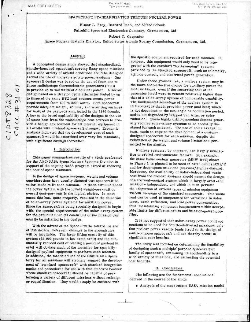
I Mount I Fig. 1 ' I 150 Watt Radioisotope Thermoelectric Generator (RTG) i for the post-1979 time period revealed that many different missions can be divided into just a few groupings of common power, weight, and size.
• Two standard radioisotope-powered spacecraft, using present-day technology, can satisfy 80 - 90 per cent of the unmanned earth-orbit missions listed in the NASA mission model for the 1979- 1990 period. The spacecraft provide structure, thermal control, electrical power, attitude and velocity control (AVCS), and tracking, telemetry, and command (TTC) subsysteiiis. The only missions excepted are those few which exceed either the weight-carrying capacity or the attitude control accuracy of the spacecraft as currently designed.
I • Two nuclear power system designs, one for each spacecraft, can satisfy all the missions served. The systems are the Radioisotope Thermoelectric Generator (RTG) and the Radioisotope Brayton (RIB) system. For each spacecraft mission, power is provided as required
' in modular steps, either by addition of complete RTG's to provide power up to 450 watts(e) or by adding fuel capsules to the Brayton system to cover the range from 500 to 2000 watts(e). Both systems can use the same standardized heat source. ]
I • Waste heat from the nuclear generators can be used to maintain spacecraft equipment temperatures within acceptable limits for all altitudes, sun angles, and equipment duty cycles. This is the key factor which permits standardization of the entire spacecraft despite the wide variety of mission conditions encountered.
I • Savings of 64 percent for four missions using ' the standardized RTG spacecraft and 43 percent for ' six missions using the Brayton spacecraft, in com-I parison with mission-specialized solar-powered spacecraft, were estimated on the basis of the cost model in the USAF Space Planners Guide. The calculations included both recurring and non-recurring costs , but
excluded specialized payload equipment, launch, and operations costs . The savings over these missions, over and above those to be derived from the component and subsystem standardization program, are estimated to be 1.7 and 2.6 times the respective development cost of the standardized spacecraft. Thus the development cost can be amortized over relatively few missions and savings thereafter are appreciable.
i n . Functional Requirem.ents and Mission Analysis
! A goal of the study is the conceptual design of nuclear-powered spacecraft capable of satisfying many different NASA missions without significant change in the standard spacecraft or their subsystems. The missions considered were those listed in the 1971 and 1972 NASA mission models (•'•), *''̂ with manned and interplanetary missions excluded by direction.
I The mission models were reviewed to classify the . demands made upon the various subsystems in order to
furnish a basis for common designs. The analysis showed a high degree of commonality in functional demands, e .g. the greatest number of spacecraft are earth oriented, with a small number of observatories pointed toward the sun or other celestial objects. Three axis stabilization is required or desirable in most cases. Pointing accuracy of 0.1 degree satisfies the needs of most missions. Higher accuracy is ordinarily required only in knowledge of the orientation, and can be provided by the addition of appropriate sensing equipment and of ground data reduction as required. Telemetry, Tracking, and Command (TTC) requirements involve a fairly low data rate which fits within either VHF or S band and both are compatible with vehicle orientation and with pointing accuracy requirements. High data rate payload communications could also be served if a tracking and data relay satellite system (TDRSS) becomes available. If a few specialized missions with very unusual parameters are removed from consideration, it becomes possible to satisfy most of the r e maining missions with a limited number of choices corresponding to the mission parameters . The excluded missions were the large observatories, whose weight requirements substantially exceed those of all other missions, and certain physics experiments, such as a relativity experiment with extremely precise attitude control requirements. The large observatories could possibly be served by yet another standard space-
j craft, but time did not permit such an investigation In this preliminary study. ]
I The remaining missions, mostly earth observation, communications, and navigation, were then divided into two groups, depending on whether their electric power requirements were more or less than 500 watts. This rather arbitrary division corresponds to the power ranges chosen for the RTG system (up to 450 watts) and for the Brayton system (above 500 watts). The study showed that, with two exceptions, the missions involving the lower power levels also involve spacecraft weighing less than 2000 pounds, while in general the missions requiring more than 500 watts involve weights above 2000 pounds. It was therefore decided ,
z
AlAA COPY SHEETS Por 8 ' : X 11 sheet Type page s .eral 1 -
Tr. is shoe* 'c be r 77% c' - , p„
that the entire range of requirements could conceivably be met by only two different spacecraft designs. This was subsequently verified by testing the designs against a number of specific missions with differing requirements.
Although the number of such test cases was necessarily limited, these were selected as representative of NASA missions with quite diverse requirements. ;
Clearly, the use of a multi-purpose spacecraft for most missions will result in many flights which do not appear "optimum" when viewed by current standards.
I For example, a spacecraft with a gross weight of 3000 pounds might be used to carry mission equipment
I which could conceivably fit within a 2000 pound space-i craft. At present, such poor design could result in mil-I lions of dollars of increased launch costs. In the j Shuttle era , however, the cost of the "excess" weight ! could be entirely trivial, especially when compared \ to the potential cost benefits resulting from the elimination of the need to design, fabricate, and qualify an
I entirely new spacecraft for each mission. i
Table 1 lists the design criteria which were applied to the standard spacecraft, based on the study of mission requirements.
Table 1 Standard Spacecraft Design Goals
r
j FUNCTION
1 Power ' ,,
Weight ' -
1 Ferrying
I Propulsion
1 AtUtude Control
T T A C
Orbit
Lifetime
j Thermal Environment
I Orientation
BEQUIREMFNT |
RTG SPACECRAFT
100 • 4S0 W (e)
1000 - 2000 lbs.
BRAYTON SPACFCR.XFT 1
500 -2000%{e) [
up to 4000 lbs. I
interface with Shuttle, Agena or Centaur Tug, Chemical Tug 1
small orbit change and/or station keeping capability 1
28 Volt DC + 2% regulation [
3 - axis stabilized, 0,1 - degree accuracy ' [
Standardized, I MBS data rate [
low to synchronous; any inclination, eccentricity [
minimum of 3 years of expendables
equipment maintained -10 to +40C for all orbits
completely arbitrary in all orbits |
r v . Nuclear Power Systems
The nuclear power systems postulated in the design study are the MHW-RTG ^K^'^\ (Fig. 1) and the Radioisotope Brayton (RIB) system (5). Both systems
1 use the same standard heat source; the 2400 watt (thermal) Helipak heat source. This heat source, designed for service at 2000° F, will be used at a maximum surface temperature of 1800° F in the RIB system.
Studies under NASA contract have shown that the same Brayton system can be used with high efficiency
over a large range of output power by varying only the heat input and system, gas pressure . This is a par t i cularly useful characteristic where system weight is not of primary importance. An attractive option under
; these circumstances is to design the system for mini-, mum weight at a relatively high power level; e . g . , using three heat sources. This same system can then be used with either one or two heat sources with little or no loss in efficiency. In fact, with two heat sources,
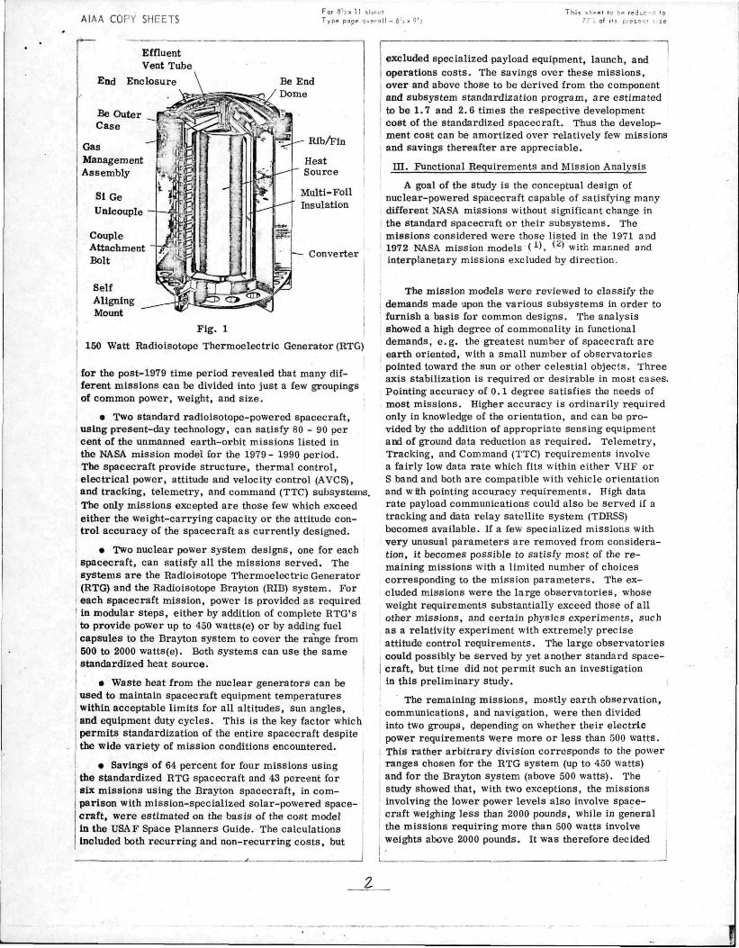
1 system efficiency is predicted to be somewhat higher because the oversized (for this case) radiator will reduce the compressor inlet temperature nearer to the optimum efficiency point. The nominal operating conditions are listed in Table 2 for the RTG and RIB systems.
: Table 2. Power System Characteristics
PARAMETER
No. of Heat Sources
Max. Power, BOL. W(e) •
Net Conversion Efficiency, BOL, "e •
Working Huid Gas Flow Bate, ih/sec
System Total Weight, lb '
Output Voltage, VDC •
Generator Envelope^ length, in.
diameter. In.
Max. Cycle Temperature, ' F
Nominal Radiator Temp. ' F *
MHW/RTO
1
150
6.25
-83
30
21.
16
1800
550
1
689
23.7
0.1
651
RIB
2
1588
• 33.1
0.2
696
3 1
2273
31.6
0.3
741 1
120
60Jdepends on
60T packaging;
1600 1
300-70
• Values subject to modiftcatlon by manner of integration of power system with spacecraft
V. Space Shuttle System
The assumed delivery vehicle is the shuttle orbiter, which has a cylindrical payload compartment 15 feet in diameter and 60 feet long. It is equipped with a remote manipulator system which can be used to handle payloads or to transfer fuel capsules, if this should ultimately prove to be desirable. The shuttle system can boost up to 65,000 pounds into a 100 nautical mile circular orbit (28.5° inclination); 40,000 pounds into a polar 100 n .mi . orbit, or 50,000 pounds into a 270 n .mi . orbit at 28.5° . For normal boost periods,
I adequate heat storage is readily available in the shuttle I to handle the waste heat from, the radioisotope sources ' In the RTG Brayton systems. The doors of the payload I bay would normally be opened after leaving the atmosphere, which permits direct radiation of the heat to Space. Extended storage periods in the shuttle, particularly with bay doors closed, requires auxiliary heat storage or cooling, since the active temperature control system now planned for the shuttle payload compartment cannot handle the heat from the radioisotope sources.
VI. RTG Standard Spacecraft
The standard RTG-powered spacecraft which evolved from the study, shown in Fig. 2, has the form
5

AlAA COPY SHEETS -7 -.1 For 8'?x 1 1 sh^-^t
Type poge overo 11 - 6'j This sheet to be r" I-.r-'d tc
77 ot (ts prei,i^!it size
Attitude Propulsion Control Nozzles Thruster
Hydrazine Tank
Viewing Por ts -Plugged If Not Used
Table 3 Equipment List, Basic RTG Spacecraft
RTG
Fig. 2 Basic RTG Spacecraft-External View
of a hexagonal prism six feet across and three feet high. The space in the center is occupied by a hydrazine fuel tank and a set of thrusters used for orbit adjustment. Vehicle weight, including payload, can range from 1000 to 2000 pounds, depending on payload and power r e quirements .
Fig. 3 Equipment Placement in RTG Spacecraft
Three compartments of the hexagonal prism contain the standard subsystems (Fig;ure 3) and three compartments are available for payload. Viewing or communicating equipment requiring a clear field of view is mounted at one end of the prism; for example, in earth-oriented missions, at that end which faces earth. Electronic and other temperature sensitive payload is mounted internally on the panels forming the two ends
I of the spacecraft. The faces have mounting holes and 'connectors for flexible payload placement. Large temperature-insensitive payload components, such as
'antennas, are mounted external to the spacecraft. I Depending on the power level required, one, two, or three RTG units are mounted externally on the side
l&ces of the prism, multiple units symmetrically and la single unit suitably counter-weighted. Access to internal equipment is through those side faces not bearing RTGs.
ITEM 1 2 3 4 5 6 7 8 9
10 11 12 13 14 15 16 17 IS 19 20
N \ M E i t l ^ C T l O N WHEEL EARTH SE.SSOH ELECT. EARTH SEKSOR COMPUTER SUN SENSOR ELECT. RATE GYRO SUN SENSOR ACTUATOR ELECT. SHUNT LOAD CONTROLLER POWER CONDiTlON, VHF .XMITTER LDR MULTIPLEXER BATTERY RECORDER MDR MULTIPLEXER S-BAND XMITTER COMMAND DECODER VHF RECEIVER S-BAND RECEIVER
Q r i SIZE 13.7 DIA. X 4 7 8 .5 X 8.0 X 8.0 5 . 5 X 5 . 5 X 5 . 0
1 2 . 0 X 1 1 . 0 X 8 .0 4 . 0 X 5 . 7 5 X 5.25 4 . O X 6 . 0 X 4 . 0 l . O X 2 .0 X 3 . 0 9 . 0 X 1 2 . 5 X 7.4 3 . 5 X I O . O X 2 . 5 5 .0 X 5 .0 X 5 .0 6 .0 X 8.0 X 12.0
11 .0 X 11 .0 X 2 . 0 6 . 0 X 1 0 . 0 X 6 .0 8.5 X 6 .0 X 11 .5
15 .0 X 4 . 5 X 15 0 6 . 0 X 1 0 . 0 X 6 .0
I I . O X U . O X 2 .0 6.0 X 10 0 X 4 . 0 9 0 X 9 0 X 2 .5 9 . 0 X 9.0 X 2 .5
vn. (i-A.) 19.7 13.0
1 0 22 .0
3 .0 4 . 0 1.0
20 .0 2 . 3 3 .0
17.6 4 . 0 6 .0
37 .0 20 0
6 0 4 . 0 5 .0 6 0 8.0
j Standard subsystems, listed in Table 3, include a ' 28 volt DC regulated (± 2%) power supply and a VHF and S band telemetry system with a 10^ bit/second capacity. The hydrazine propulsion system has fuel capacity for at least a 1170 foot/second velocity increment; because the thrusters are fixed, large increments will require spinning the vehicle. The configuration is chosen to facilitate balance and mass distribution suitable for stable spinning about the thrust axis . Small velocity increments, such as are applied in stationkeeping, do not require spinning; the attitude control system offsets any momentum due to mis alignments of the central thrusters from the centroid of the vehicle. The three axis stabilization system employs reaction wheels and the hydrazine monopro-pellant thrusters for unloading the wheels, when necessary. Temperature of the hydrazine tank is suitably regulated by electric heaters .
The thermal control system provides a regulated environment between -10°C and +40°C for all spacecraft internal equipment in all conditions, i . e . regardless of occultations of the sun, aspect of the sun, earth albedo radiation and internally generated heat from spacecraft and mission equipment. This thermal independence of mission conditions makes it possible for the spacecraft to be used for a variety of missions. This is achieved by a thermal control system which uses part of the waste heat from the RTG units to overcome variations in heat originating from all other sources.
The case and fins on the RTG radiate most of the heat produced directly to space; their high temperature makes them effective radiators . Between the surface plate bearing the RTG and the rest of the spacecraft is a louver system which controls the rate at which heat is radiated from this plate to the other parts of the spacecraft. The m.ovable vanes of the louver system automatically regulate the spacecraft temperature against variations due to changing heat inputs from other sources. The temperature of the spacecraft end panels is maintained relatively uniform by the use of heat pipes on the end faces of the pr ism. Standard emissivity coating and insulation techniques control the payload compartment temperature within the proper range despite differences in equipment power level
{and s o l a r - and earth-originating radiation.
JL
AlAA COPY SHEETS For fl J« 11 shi-et
Type poge ovn oil —6 1 . 9 ' j
Th is s\:rft to 1 f- reJur" . ! t i
7 7 ' of * . pri»'^nt ^1 •'•
4 8 0
<
H 320
r4
< - . 240
s -
— o
^ CO
53
160
80
NO EXTERKAL INPUT;
450 W. FROM RTG -V
1 ..NO FXTKRNAT,
I N P U T ; 360 W . ^ ^
FROM RTG ^ S , ^
(EOM)
/y / /
/ /
/
// / /
/ / 1
'1 ,
/ / ' /
/ /
/ / //
1 1 / / / 1
1 / /
/ /
" SPACE POINTED FACE ~]
/
^ /
/
/ /
/
200 N.M. b R s r r
y ^
/ ^ / 7 /
/
/
/ -
K
\ / 1 \ 1
/ EARTH VIEWING FACE ' 200 N M. ORBIT
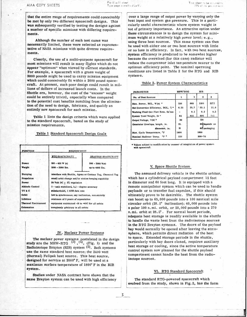
placing bending moments on the orbiter vehicle. Validity of the standard spacecraft concept was
tested against the specific requirements of two different missions.
Orbiter Dynamic Envelope
-10 0 10 20 30 40
PANEL MEAN TEMP. ("C)
Fig. 4 Mounting Panel Temp. Range, RTG Spacecraft
Fig. 4 shows the effect of variations in power levels and mission conditions on the temperature of the end panels that support the equipment. These curves demonstrate the effectiveness of the system in providing a satisfactory environment in all conditions.
Table 4 RTG Spacecraft Weight Estimates
PHIMAHY bllUCTI lU
• SHt LIS • ItUlb • niNcs • 31 PPOUI l-TG H I • STIJFhNHtS • ItTC SI PI (11 • LONftO iia,)
t4 0 2T 0 M 5 M S 20 0
r 0 K. U (190 0|
. w i 1PM* V r M ppoK r f l lacTuiu • t L t C l P(J»tR • •ips • T t L t t LOMMAMl • (.OMM • LXPt-RJMtNTS
THtKMAL rOVfROL • INSLLATION • COATINOS • HLAT PlPtS • VANtSni • RTO ltAI>IAT01tS|31 • ISULATUItS ft HEATF Its
ELECTRICAL POtVEK SI STE.M
• RTG (3) • BATTEIIV • SHI NT REG • f A L L T DETFCTOIt • 9HIINT CM-WIPATORS
3 0 7 0 4 0 \ 0 TO {2 > 01
IM 2
2 S 31 0 fr 9
14 4 5 0 (7H Oi
240 0 37 0
3 a fi 0 T 1
ELECTRK M P imVU SYS PI-M • PO»M< (.UNUII M l • LOAD (ONTUDLI H I • B A T T t l l Y C O M • MISC
<> O M 17 fi 1 0 1 0 5 0
S/C PROPl LblON ANl l ATTIT I l>E CONTKOL S^Srt-M
• TANKS • P I lOPtLLANT • SENSORS • UHt l -LS IS ) • ELECTROSICS • COMPLTMtS
TELE ft COMMANI l inSTEM • 3 BAND I te i -
• S BAND TRANS • VH» RFC • VHF TIUNS • LDR M I X • MDR M I X • l lECOimni.S(2> • CMD DFCDDbK
BASIC S C W U C J H T
MISSION E Q I I P M E M
TOTAL V C WEIGHT
25 0 172 0 2S 0 SH 0
20 0 4S 0
8 0
4 0 6 0 f 0
a 0 6 0
4U 0 5 0
*
VI i i),
(3ao Oi
(84C 0|
(79 01
i i 2 i r 01
an4 Oi
(ZOOO 0)
Table 4 is a weight breakdown by subsystem of the maximum size 2000 pound RTG spacecraft carrying three RTG units. Note that this includes a large amount of propellant (370 lbs) for orbit adjustment purposes, and a battery in the electrical system to provide for periods of peak power exceeding the RTG capacity. Mission equipment weight allowance is 764 pounds.
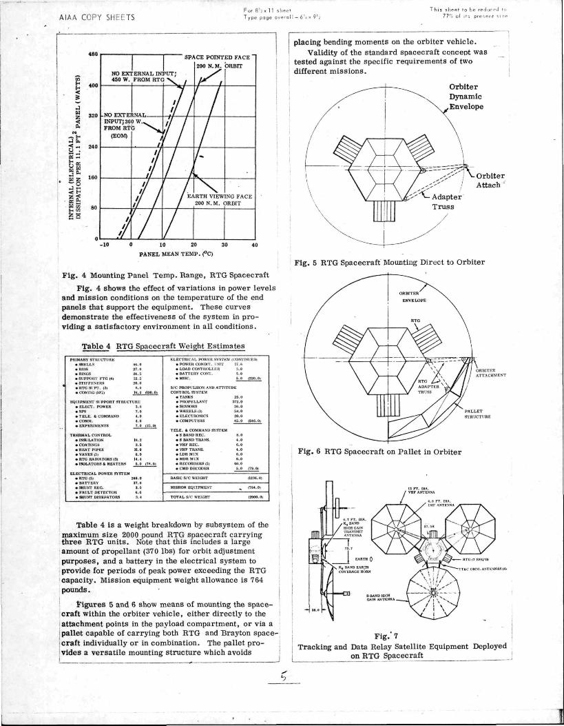
1 J"igures 5 and 6 show means of mounting the spacecraft within the orbiter vehicle, either directly to the attachment points in the payload compartment, or via a pallet capable of carrying both RTG and Brayton spacecraft individually or in combination. The pallet provides a versatile mounting structure which avoids
Orbiter / Attach '
Fig. 5 RTG Spacecraft Mounting Direct to Orbiter
ORBI rFR ATTACHHE»4T
PALLET
STRUCTLRE
Fig. 6 RTG Spacecraft on Pallet in Orbiter
t
1 ( 1
-
ill
r 3S 0 [<
< .-
/
-^-4 7 FT DIA
-K^BA-fD ' HirHCAIN
TIIAVSMIT A^T^•^SA
< .
> / (-
• \
^
1 EARTH i;
S Ku BAND EARTH COVERAGE HORN
^ \ /
^ " ^ - ^ S^BANO HIGH GAIN ANTENNA —
13 FT DIA / VHF ANTENNA
/
=4̂
\>s
« 8 FT DM / I'M* ANTFVNA
57 SH
/
^>T f^A/y
S~~^^>^ \ / 1 \ /
\
— RT<
~TT4C n
\ / /
Tv
^ \ / 1 RKj m
MNl ANTtNNA^(4(
,
Fig. 7 Tracking and Data Relay Satellite Equipment Deployed
on RTG Spacecraft
•p
AlAA COPY SHEETS For 8 ' . X 11 i h e e t
T ypp page o v f r a l I -
T h i s sheet
7 7 ' , of
o be r ^ i j u r p d to
Its p ru . . . nt -.1/1
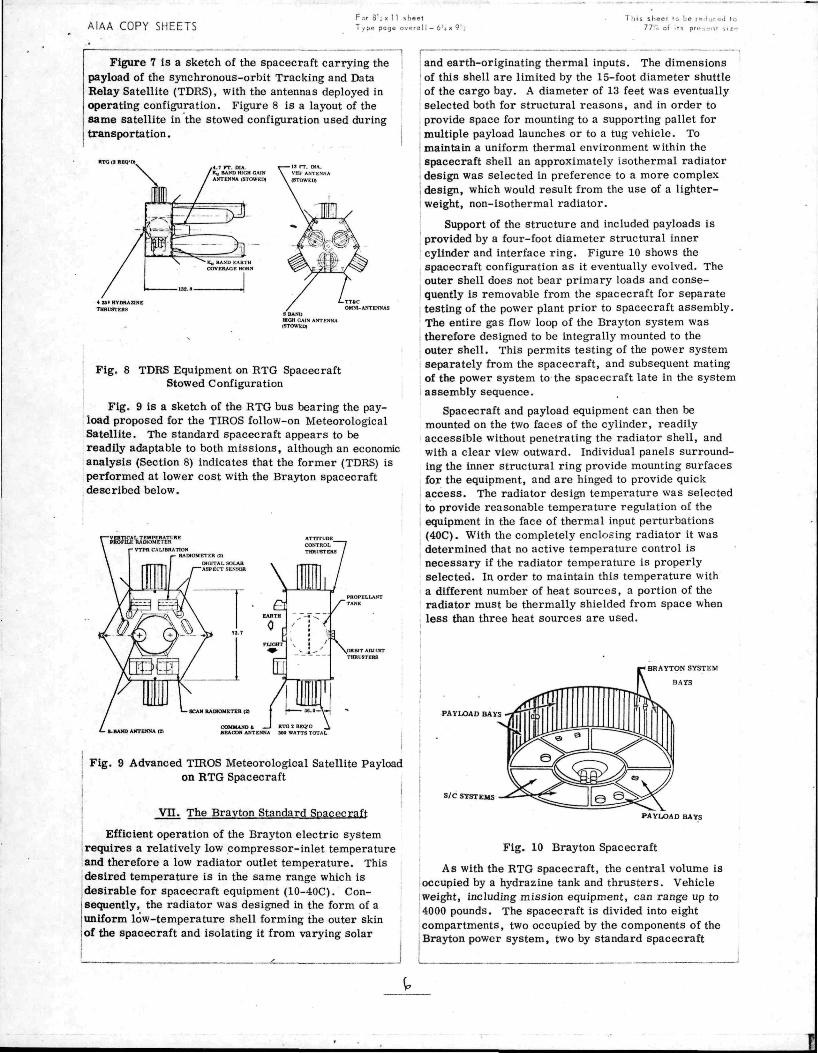
Figure 7 is a sketch of the spacecraft carrying the payload of the synchronous-orbit Tracking and Data Relay Satellite (TDRS), with the antennas deployed in operating configuration. Figure 8 is a layout of the same satellite in the stowed configuration used during transportation.
RTG 13 REQ'O) 4 T r r DIA K., BAND HIGH CAIN ANTENNA (STOWEIH
•13 FT MA VflF AVTE'4NA (STOWEDt
9 BAND mCH CAfi ANTENNA (fftXJWEDJ
Fig. 8 TDRS Equipment on RTG Spacecraft Stowed Configuration
Fig. 9 is a sketch of the RTG bus bearing the pay-load proposed for the TIROS follow-on Meteorological Satellite. The standard spacecraft appears to be readily adaptable to both missions, although an economic analysis (Section 8) indicates that the former (TDRS) is performed at lower cost with the Brayton spacecraft described below.
. 8.BAia> AtTTENNA (2)
Fig. 9 Advanced TIROS Meteorological Satellite Payload on RTG Spacecraft
i
v n . The Brayton Standard Spacecraft
Efficient operation of the Brayton electric system requires a relatively low compressor-inlet temperature and therefore a low radiator outlet temperature. This desired temperature is in the same range which is desirable for spacecraft equipment (10-40C). Consequently, the radiator was designed in the form of a uniform low-temperature shell forming the outer skin of the spacecraft and isolating it from varying solar
and earth-originating thermal inputs. The dimensions ' of this shell are limited by the 15-foot diameter shuttle of the cargo bay. A diameter of 13 feet was eventually selected both for structural reasons, and in order to provide space for mounting to a supporting pallet for
I multiple payload launches or to a tug vehicle. To I maintain a uniform thermal environment within the spacecraft shell an approximately isothermal radiator design was selected in preference to a more complex
I design, which would result from the use of a lighter-I weight, non-isothermal radiator.
Support of the structure and included payloads is provided by a four-foot diameter structural inner
' cylinder and interface ring. Figure 10 shows the spacecraft configuration as it eventually evolved. The outer shell does not bear primary loads and consequently is removable from the spacecraft for separate testing of the power plant prior to spacecraft assembly. The entire gas flow loop of the Brayton system was
' therefore designed to be integrally mounted to the ' outer shell. This permits testing of the power system separately from the spacecraft, and subsequent mating of the power system to the spacecraft late in the system assembly sequence.
Spacecraft and payload equipment can then be mounted on the two faces of the cylinder, readily accessible without penetrating the radiator shell, and with a clear view outward. Individual panels surrounding the inner structural ring provide mounting surfaces for the equipment, and are hinged to provide quick access. The radiator design temperature was selected to provide reasonable temperature regulation of the equipment in the face of thermal input perturbations (40C). With the completely enclosing radiator it was determined that no active temperature control is necessary if the radiator temperature is properly selected. In order to maintain this temperature with a different number of heat sources, a portion of the radiator must be thermally shielded from space when less than three heat sources are used.
BHAYTON SYSTEM
B4YS
PAYLOAD BAYS
SIC SYSTEMS
PAYLOAD BAYS
I Fig. 10 Brayton Spacecraft
As with the RTG spacecraft, the central volume is occupied by a hydrazine tank and thrusters . Vehicle
iweight, including mission equipment, can range up to 4000 pounds. The spacecraft is divided into eight compartments, two occupied by the components of the
I Brayton power system, two by standard spacecraft
^

AlAA COPY SHEETS For 8';« 11 Lhci-I Type page overall — 6 ' j x 9 ' ;
This shfet to \if reduced to 77"j of Its present si-'*-
'subsystems, and four available for mission equipment j(Fig. 11). For the earth-viewing missions, one end of ;the cylinder is pointed toward the target and directional lequipment is mounted on this face. The two faces of the cylinder provide mounting surfaces for the spacecraft equipment and dissipate heat originating within ithe equipment. Temperature sensitive components are mounted inside the spacecraft; large temperature-insensitive components can be placed outside.
BYDHAZiNE PROPELLANT TANK (42.0 DU. SPHERE)
TUBUSTERS I4| IS t
(m YAW CONTROL TURUTTERS
PITCH CONTROL THRUSTERS |4)
INl-BRAYTON SYSTEM TLRDIVE - GENERA TOR - COMPRESSOR RADIOI.s^>TOPE HEAT SUl'RCE RECLPERATOM
SPACECRAFT PICK-UP* ATTACH POINTS 4 PLCS ITYP.IT
(4) ROLL C O N T R O L / ' THRUSTERS.
Fig. 11 Basic Brayton Spacecraft
Relatively uniform radiator temperature is achieved by dividing the Brayton working fluid into two streams which encircle the radiator in opposite directions. Figure 12 shows typical temperature profiles around the radiator circumference resulting from this counter-flow arrangement. Heat is distributed over the entire radiator surface by axial heat pipes. The heat is radiated both outward to space and inward to the pay-load for thermal control.
C O U K T E R F U I W OAS DOCTS
RADIATOR 9 a N
CAS FLOW PATHS
T E M P E R A T U R E P R O F I L E S
TEliPERATURE
HADIATOH T E M P E R A T U R E
Fig. 12 Isothermal Radiator Configuration
The thermal control system differs from that of the RTG spacecraft in that heat input from the radiator is not varied with different conditions. However, it still provides environmental conditions between -10°C and +40°C for all spacecraft equipment in all conditions. Thus the Brayton satellite is adaptable to arbitrary earth-orbit mission conditions as required by the design goal.
Many subsystems, such as telemetry, propulsion and attitude control, are substantially identical to those of the RTG spacecraft except for size. The fixed-nozzle thrusters still require spinning the spacecraft to ac
complish large velocity increments, and the configuration is arranged to give moments of inertia which provide stable spinning about the thrust axis. The AC power output of the Brayton alternator is converted to 28 volt DC, regulated to ± 2%. The power system provides parasitic loads to keep the Brayton unit operating at a constant speed of rotation despite variations in equipment load.
Table 5 is a weight breakdown for a 4000 pound spacecraft with three radioisotope fuel capsules and 560 pounds of propellant. The mission equipment allowance is almost 1900 pounds.
j Table 5 Brayton S/C Preliminary Weights
PRIMARY STRLCTLRE • SHELL • RIBS • RINGS • 3TIFFENERS • BRAYTOM SPT. STH • BUS SPT. STR. • CONTIC |ID%|
U 3 . 0 5ft. S B3.9
7 . 3 18 0 W.O 37.11 (404 3 |
EQI'lPMtCNT SCPPORT S T R I T T r R t • E L E C T . POWER • SPS • I ELE. It COMMAND • COMM. • EXPERIMENTS
THERMAL CONTROL • HEAT PIPES • INSULATION • COATINGS • PAINT • HEATERS • MISC. ISOLATORS
ELECTRICAL PWR. S^ S. • GAS RADIATOR • HEAT SOURCES (3) • RECUPERATOR • TURBINE
5. 10. 5 5.
10. I3S OI
M . O 3 5 . 0 17.0 5 .7 S.O 5 .0 (121.71
(BRAYTON I NIT) 9 2 . 0
305.0 S 8 . 0 2 9 . 0
ELECTRICAL PW R. S \ S . iBRAVTOS I M T . 1 (CONTIM tDi
• P L l M n i N G 12.0 • E L t C r R O N I C S 15.0 • BATT b I N V E R T t R 5 9 . 0 • P L R 20 .0 • INS! LATION 109 2 (705 Z»
3 / C P R O P l LSION AND ATTITl 'DE CONTROL SYSTEM
• TANKS 3 2 . 0 • PROPELLANT 560 .0 • SENSORS IT.O
• U H E E L S I 3 I JM.O • C O M P M E R S (2j 4 5 . 0 • ELECTRONICS M 0
T E L E , ft COMMAND SYSTEM • 3 B.\.NI> R E C . d.O • S BAND TRANb. 4 . 0 • vm KEC. 6 . 0 • VHF TIL^NS. 4 . 0 • LDR MCX 6 . 0 • MDR M l . \ S.O • CMD DECODER 5 . 0 • H t L O R U E R S ( 2 ) 4 0 . 0
BASIC s ' c W t l C H T
(75ft. OI
(79. Oi
(210) Jl J 1 .MISSION b W l i f M L N I t l - i i , rt, I
TOTAL SPACLCItA I T HOOO.iJ) j
I The adaptability of the standard Brayton spacecraft ' to two Specific missions of diverse requirements was ' confirmed by detailed studies. Fig. 13 is a sketch of Earth Observation Satellite (EOS) equipment de-
'N
Fig. 13 EOS Equipment on Brayton Spacecraft j
1

Figures 14 and 15 show Applications Technology Satellite ATS-F equipment mounted on the spacecraft, in deployed and stowed configurations.
Vni. Cost Analysis
BHAYTON S/C
D N ENGINE
C- SAND TRAjaMTTT BORN (2) COARSE SVN
SENSORS EARTH COVERAGE HORN (C- BAND RECEIVER)
Fig. 14 ATS-F Equipment Deployed on Brayton Spacecraft
m OQAR3E Sf
BRAYTON S/C
EARTH OOVEBAOE HORN (C • BAMO RKCEZV
Fig. 15 ATS-F Equipment on Brayton Spacecraft -Stowed Configuration
Fig. 16 shows both RTG and Brayton spacecraft on the same pallet within the orbiter.
^' Fig. 16 RTG and Brayton Spacecraft Stacked on Pallet
Cost studies were carried out to compare standardized nuclear-powered spacecraft with mission-specialized (or "dedicated") solar-powered spacecraft. Attention was limited to ten missions from the NASA 1972 mission model which are now planned for the post 1979 period: five below 500 watts and five above 500 watts, i . e . in the RTG and Brayton system power ranges.
Launch costs, operational costs, and specialized mission equipment costs were not considered in this phase of the study. No detailed analysis was made for the cost increases for handling nuclear fuel, nor for reduction in launch and operational costs due to standardization. These two factors were assumed to offset each other. Mission equipment costs should be relatively unaffected by the nature of the spacecraft. In view of the relative imprecision of cost models, it was assumed that these particular costs are the same for both types of spacecraft, and attention was limited to the actual spacecraft costs and to the costs of the standard equipment provided for all missions.
The cost model was drawn from the section of the USAF Space Planners Guide dealing with space vehicle system costs . It divides the costs into non-recurring costs, involving development, test, and evaluation (DTE), facilities, and aerospace ground equipment (AO;), and recurring costs of production and operations. The operations costs are not included.
Within each category, costs are broken down by subsystems, and estimated from a set of curves which usually plot cost against weight. In most cases several different curves are furnished to cover different types of each particular subsystem. While the subsystem cost estimates may not be accurate, the total system costs do provide a reasonable reflection of existing system costs . The model is thus useful for quick estimates of total system costs during early stages of conceptual design.
Since the model was prepared in 1965, costs were first increased by 30 percent to reflect inflation. The non-recurring DTE costs were then decreased by 25 percent to reflect the savings due to the NASA subsystem standardization program. The estimated weight of the dedicated spacecraft was assumed to be less than that of the standardized designs, since the former could presumably be more efficient in weight utilization by virtue of addressing only one mission rather than providing capability for a variety of missions. In the USAF cost models, this weight difference imposed a penalty on the standardized spacecraft, since all the spacecraft subsystem cost curves showed increasing cost with increasing weight.
Recurring costs were also estimated as a function of weight (or power, for the power subsystem only), with an initial unit cost modified by a set of "learning curves" to reflect the effects of the size of production runs. In general, the recurring costs for the standardized spacecraft are higher than those for the dedicated spacecraft, while the non-recurring costs are lower, since most of the DTE spacecraft costs were eliminated by the use of a standard design.
COST COMPARISON TOR FOUR LOW-POWER MISSIONS* STANDARDtZED RTG a'C VERSUS SPECULIZED SOLAB-POWERED S/C
In Millions of OollarB**
COST COMPARISON FOR SK MEDIUM-POWER MISSIONS* STANDARDIZED BRAYTON S/C VERSUS SPECIALIZED SOLAR-POWERED S/C
In MlUionB of Doltsrs**
MISSION
FLIGHTS
STANDARD S/C (Nuclear)
Non-Recurring
RffcurrlnK
TOTAL
SPECLALIZED S/C (Solar
Non-Recurrfng
Recurring
TOTAL
RTG S/C SAVINGS
Upper Atmos Epior
6
1.1
32.6
3 3 . 7
53.4
15.5
68 9
35 4
COST OF DEVELOPING STANDARD
' NET SAVINGS. After Full Amortlza 1 of thp Standard S/C I
Synch Meteor
Sat
2
1.8
10.9
1 2 . 7
37.1
3 7
40 s
28 4
TO"
S / C
Ion Over ' aeielopme
TIROS
I
S.9
7.9
1 3 . 7
50.5
3.7
54 3
42 0
77';
Geopause
2
7 . 1
10.9
18 .0
43 5
5 7
U 2
3fl 0
70^
hese FQ nt Cost
ur Missions
TOTAL
U
1 5 . 9
62 2
7 8 . 1
189 S
28 6 1 21« 1
140 .0
64%
61.0
5 9 . 0 27%
.*Cogta Include; Standard S'C Subsystema iStructure. Thern-aJ. Power. Attitude Control. Teleinetry. Command). AGE. and DTE
Coats Exclude: Specialized Miaslon Equipment. Launch, and Operation
• • B a s e d on US.^F Space Plannera Guide Cost Formula. Plus 30^ for Inflation, Component and Subsystem Standardization Assumed to Reduce DTE Costs OyZoT tor •pectaUzed S /C only.
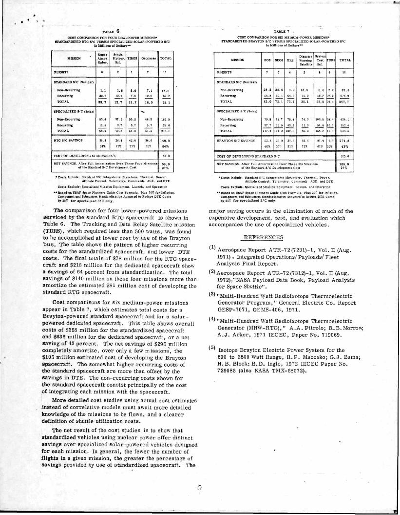
The comparison for four lower-powered missions serviced by the standard RTG spacecraft is shown in Table 6. The Tracking and Data Relay Satellite mission (TDRS), which required less than 500 watts, was found to be accomplished at lower cost by use of the Brayton b u s . The table shows the pattern of higher recurring costs for the standardized spacecraft, and lower DTE costs . The final totals of $78 million for the RTG spacecraft and $218 million for the dedicated spacecraft show a savings of 64 percent from standardization. The total savings of $140 million on these four missions m.ore than amortize the estimated $81 million cost of developing the standard RTG spacecraft.
Cost comparisons for six medium-power missions appear in Table 7, which estimates total costs for a Brayton-powered standard spacecraft and for a solar-powered dedicated spacecraft. This table shows overall costs of $358 million for the standardized spacecraft and $636 million for the dedicated spacecraft, or a net saving of 43 percent. The net savings of $295 million completely amortize, over only a few missions, the $105 million estimated cost of developing the Brayton spacecraft. The somewhat higher recurring costs of the standard spacecraft are more than offset by the savings in DTE. The non-recurring costs shown for the standard spacecraft consist principally of the cost of integrating each mission with the spacecraft.
More detailed cost studies using actual cost estimates instead of correlative models must await more detailed knowledge of the missions to be flown, and a clearer definition of shuttle utilization costs .
The net result of the cost studies is to show that standardized vehicles using nuclear power offer distinct savings over specialized solar-powered vehicles designed for each mission. In general, the fewer the number of flights in a given mission, the greater the percentage of savings provided by use of standardized spacecraft. The
MISSION
FLIGHTS
STANDARD S/C (Nuclear)
Non-Recurrlng
Aecurnng
TOTAL
SPECIALIZED S/C (Solar)
Non-Recurrlng
Recurring
TOTAL
BRAYTON S/C SAVINGS
E O S
7
2 5 . 2
56.8
82 .0
79 5
37.7
117 2
53 3
4 6 ?
SE03
5
2 5 . 0
50
7 5 .
7? 7
25 5
104 2
J3 9
3 3 '
E R S
8
8 . 2
64.9
73.
79 4
43.1
122 ;
37 ^
3 1 1
COST OF DEVELOPING STANDARD S C
Dlaaater Warning Satellite
2
13.9
16 2
30 .1
74 3
11 0
35 3
62 6
7 3 1
NET SAVINGS After Fall Amortization Over These Six Mlssic of the St.andard S/C Development Cost
System Teat Sat
9
3 . 3
49 7
58 .0
lOJ. 8
54.4
153 2
97 4
61 ' !
TDRS
6
2
37
3 9 .
33.4
10 7
49
9 7
20'(
na
TOTAL
3 6
8 2 . 8
274 3 1
3 5 7 . 7
454 1
132 4
b3fi 5
2 7 4 . 8 1
4 3 1 1
105 0
1 6 9 . 3 27%
•Coats Include- Standard S'C Subsystems (Structure, Thermal. Power. Attitude Control. Telemetry Command) AGE and DTE
Costs Exclude. Specialized Mission Equipment Launch, and Operation
• •Baaed on USAF Space Planners Guide Cost For—ula Plus 30^. for Inflation. Component and Subsystem Standardization Assu-ed ' to Reduce DTE Costs by 25'; fo r «pec la l i zed S/ C only.
major saving occurs in the elimination of much of the expensive development, test, and evaluation which accompanies the use of specialized vehicles.
REFERENCES
(1) Aerospace Report ATR-72 (7231)-1, Vol. n (Aug. 1971) . Integrated Operations/Payloads/Fleet Analysis Final Report.
(2) Aerospace Report ATR-72(7312)-1, Vol. II (Aug. 1972)/'NASA Payload Data Book, Payload Analysis for Space Shuttle".
^ ' "Multi-Hundred \yatt Radioisotope Thermoelectric Generator Program, " General Electric Co. Report GESP-7071, GEMS-406, 1971.
' ' "Multi-Kundred Watt Radioisotope Thermoelectric Generator (MHW-RTG)," A.A. Pitrolo; R.B.Morrow, A . J . Arker, 1971 lECEC, Paper No. 719069.
^ ' Isotope Braj'ton Electric Power System for the 500 to 2500 Watt Range, R . P . Macosko; G.J. Bama; H.B. Block; B.D. Ingle, 1972 lECEC Paper No. 729085 (also NASA TMX-6S072).
v o l II NO II NOVFMBER l')74 J SPACECRAFT 741
Spacecraft Standardization through Nuclear Power
E L M E R J F R E Y , * B E R N A R D R A A B , ! A N D A L F R E D S C H O C K {
Fairchild Space and Electronics Company Germantow n Md
A N D
R O B E R T T C A R P E N T E R §
U S Atomic Enerqy Commission Germantow n, Md
T h e m e
A CONCEPTUAL design study showed that two standardized shuttle-launched spacecraft using nuclear electrical
power could serve many missions in a wide vancty of orbits Development costs could be amortized over very few missions, with signifiumt savings thereafter
Contents
A study' ^ investigated whether the combination of the weight and volume capacity of the shuttle and the characteristics of nuclear electric power systems could make it possible to standardize spacecraft as well as subsystems The standard spacecraft must provide space mounting structure, environment and attitude control, power and telemetry for many missions with minimum changes and standard subsystems Weight, volume, and thermal and solar array requirements (orbit-imjxiscd) have usually led to custom design in the past >Juclear systems provide power and heat independently of solar ocultation and aspect, and undcgraded by Van Allen or solar radiation The study examined feasibility of standard spacecraft design, applicability to specific missions and costs
Table 1 Standard spacecraft design goals
AmruDE CONTROL IHRUSTER
PICK UP POINT
STANDARD VIEWING
PORTS TO SF PIUGCEO
If NOT USED
Fig I Basic RTG spacecraft—external view.
Presented at the 8th Intersociety Energy Conversion Engineering Conference, Philadelphia, Pa, August 13-16, 1973, submitted November 9 1973, synoptic received July 11 1974 Full paper available from National Technical Information Service Sprinafield Va 22151 as N74-31336 at the standard price (available upon request) This paper was based on work supported by the Atomic Fnergy Commission under Contract AT (49 1S) 3063
Index categories Spacecraft Configurational and Structural Design (Includmg 1 oads) Spacecraft Electric Power Systems Spacecraft Mission Studies and Economics
' Manager Systems Analysis Associate Fellow ALAA t Manager Nuclear Applications Member AlAA t Manager Nuclear Systems § Assistant for Requirements and Applications Space Nuclear
Systems Division
Function
Power Weight
Ferrying
Propulsion
Power
Attitude control T T & C Orbit
Lifetime Thermal environment
Orientation
Requirement RTG spacecnft Brayton spacecraft
100-450 w(e) 500-2000 w(c) 1000-2000 lbs up to 4000 lbs
interface with Shuttle Agena or Centaur Tug Chemical Tug
small orbit change and/or stationkeeping capability
28 v d c + 2% regulation, plus battery capacity
3 axis stabilized 0 1° accuracy standardized 1 MBS data rate low to synchronous any inclination ec
centricity minimum of ^ yr of expendables equipment maintained —10 to +40C for all
orbits completely arbitrary in all orbits
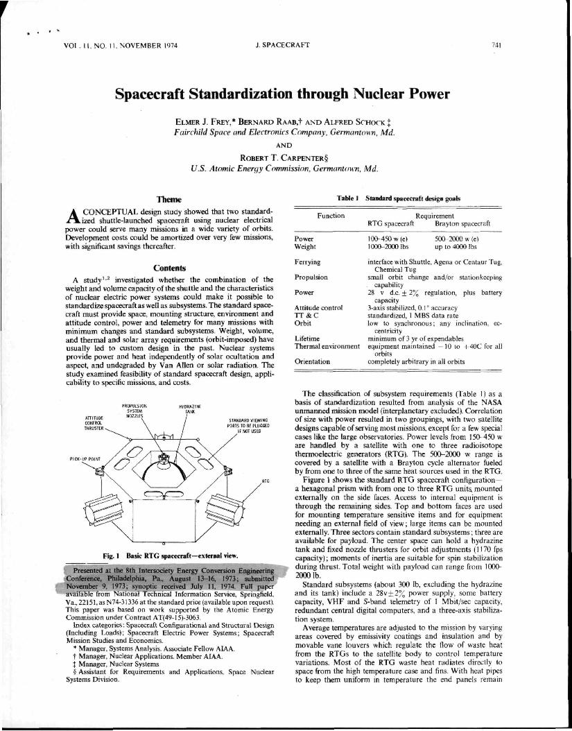
The classification of subsystem requirements (Table 1) as a basis of standardization resulted from analysis of the NASA unmanned nussion model (interplanetary excluded) Correlation of size with power resulted in two groupings, with two satellite designs capable of serving most missions except for a few special cases like the large observatories Power levels from 150- 450 w are handled by a satellite with one to three radioisotope thermoelectric generators (RTG) The 500-2000 w range is covered by a satellite with a Brayton cycle alternator fueled by from one to three of the same heat sources used in the RTG
Figure 1 shows the standard RTG spacecraft configuration— a hexagonal prism with from one to three RTG units, mounted externally on the side fates ALLBSS to internal equipment is through the remaining sides Top and bottom faces are used for mounting temperature sensitive items and for equipment needing an external field of view, large items can be mounted externally Three sectors contain standard subsystems three are available for payload The center space can hold a hydrazine tank and fixed nozzle thrusters for orbit adjustments (1170 fps capaaty), moments of inertia are suitable for spin stabilization during thrust Total weight with payload can range from 1(X)0-2000 lb
Standard subsystems (about 300 lb, excluding the hydrazine and Its tank) include a 28v±2°„ power supply some battery capacity, VHF and S-band telemetry of I Mbit/sec capacity redundant central digital computers and a three-axis stabilization system
Average temperatures are adjusted to the mission by varying areas covered by emissivity coatings and insulation and b) movable vane louvers which regulate the flow of waste heat from the RTGs to the satellite body to control temperature variations Most of the RTG waste heat radiates direi,tly lo space from the high temperature case and fins With heat pipes to keep them uniform in temperature the end panels remain