spam series
TRANSCRIPT
8/3/2019 Spam Series
http://slidepdf.com/reader/full/spam-series 1/12
SEPAM Digital Relay
Product Line Overview
Square D
Electrical
Protection
And
Monitoring

8/3/2019 Spam Series
http://slidepdf.com/reader/full/spam-series 2/12

8/3/2019 Spam Series
http://slidepdf.com/reader/full/spam-series 3/12
Schneider Electric, a world leader in digital protection units,
presents the latest generation o Square D Sepam digital relays
backed by more than 25 years o worldwide history.
Whether you are looking or a simple protection relay or a
multiunctional, communicating protection unit or remote network
management and operation, you will nd the right solution in the
Sepam series o digital protective relays. Sepam relays are ideally
suited or the most commonly encountered applications in utility
substations, industrial and large commercial environments — at
low, medium and high voltage levels.
Digital Relays to Meet Your Specifc Needs
Not only are Sepam relays a world leader in multiunctional digital
protection, but in a standard ootprint that covers virtually any
medium voltage application imaginable. Our unique design also
allows you to unctionally enhance your Sepam digital relays at any
time, with the addition o optional modules, allowing you to adapt
to as many situations as possible, and letting your system grow as
your acility does.
Over 300,000 Installations Worldwide
Schneider Electric has provided relay protection units or over
25 years. In additon to myriads o industrial and commercial
locations, we have over 300,000 protective devices installed world-
wide in critical power applications, such as standby generators
or hospitals, waste-water treatment plants, data centers and
telecommunication acilities.
Designed to Exceed the Dependability you Require
Superior, reliable unctionality is critical in the power industry.
The Square D Sepam relay was specically designed around
a dependability study to ensure maximum reliability. To take
the notion o reliability a step urther, our engineers added a
comprehensive sel-testing sequence that monitors internal health
with status indication by the watchdog relay. Following that, they
made sure our units have exceptional withstand to electromagnetic
disturbances, vibration and power system transients. Sepam
product engineers understand your requirements.
Square D Sepam Digital Relays:
A World Leader in Digital Protection Technology
8/3/2019 Spam Series
http://slidepdf.com/reader/full/spam-series 4/12
8/3/2019 Spam Series
http://slidepdf.com/reader/full/spam-series 5/12
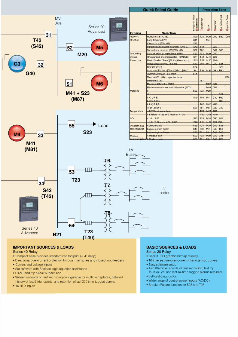
Quick Select Guide Protection Zo
F e e d e r o r m a i n
( S u b s t a t i o n )
T r a n s f o r m e r
M o t o r
G e n e r a t o r
B u s ( v o l t s / f r e q )
Criteria SelectionNetwork Radial (51, 51N, 46) S20 T23 M20 G40 B80
structure Long eeders (67N) S41 M41
Closed loop (67N, 67) S42
Parallel mains [trans] [sources] (67N, 67) S42 T42 G82
Sync-check required (25)(67N, 67) S82 T82 G82 B80
Grounding Solid or low/high impedance (51N) S23 T23 M20 G40
system Ungrounded or compensated (67N/NC) S41 T42 M41 G82
Protection Basic Feeder [Trans][Motor][Generator] S23 T23 M20 G40
Voltage/requency (27/59/81) S40 T40 M41 G40 B21
ROCOF (81R) S84 B22
Advanced Fdr/Main[Trans ][Motor ][Gen] S41 T82 M81 G82 B83
Thermal overload (49)-cable S81
Thermal O/L (49) - capacitor bank
Dierential (87T) T87
Machine dierential (87M) M87 G87
Machine-transormer unit dierential (87T) M88 G88
Metering I S23 T23 M20
V, B21
I, V, , P, E S40 T40 M41 G40 B80
I, V, V, , P, E B83
I, I, V, F, P,E T87 M87 G87
THD-I,THD-V S80 T81 M81 G82 B80
Temperature <8 RTDs o same type T23 M20 G40
> 8 RTDs (< 16) or 2 types o RTDs T40 M41 G40
I/Os < 10 I / 8 O S23 T23 M20 G40 B21
> 10 I / 8 O and < 42 I / 23 O S80 T81 M81 G82 B80
Program logic
customization
Control matrix S23 T23 M20 G40 B21
Logic equation editor S40 T40 M41 G40 B80
Ladder-logic sotware S80 T81 M81 G82 B80
Modbus
communication
1 Modbus port S23 T23 M20 G40 B21
2 Modbus ports S80 T81 M81 G82 B80
BASIC SOURCES & LOADS
Series 20 Relay
• Backlit LCD graphic bitmap display
• 16 inverse time over-current characteristic curves
• Easy sotware setup• Two 86-cycle records o ault recording, last trip
ault values, and last 64 time-tagged alarms retained
• Sel-test diagnostics
• Wide range o control power inputs (AC/DC)
• Breaker/Failure unction or S23 and T23
M4
Load
M5
M6
M41(M81)
G3
G40
T42(S42)
M20
M41 + S23
(M87)
S42(T42)
S23
B21
T23
T23
(T40)
31
52
32
33
51
55
53
54
34
MVBus
T8
T7
T6
LVBuses
LV
Loader
Series 40Advanced
Series 20Advanced
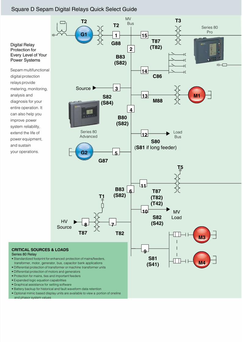
IMPORTANT SOURCES & LOADS
Series 40 Relay
• Compact case provides standardized ootprint (< 4” deep)
• Directional over-current protection or dual mains, ties and closed loop eeders
• Current and voltage inputs
• Set sotware with Boolean logic equation assistance
• CT/VT and trip circuit supervision
• Sixteen seconds o ault recording congurable or multiple captures, detailed
history o last 5 trip reports, and retention o last 200 time-tagged alarms
• 16 RTD inputs
8/3/2019 Spam Series
http://slidepdf.com/reader/full/spam-series 6/12
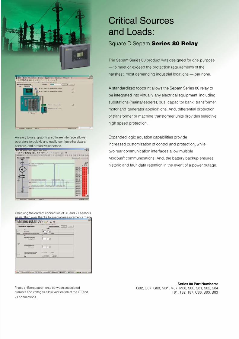
Critical Sourcesand Loads:Square D Sepam Series 80 Relay
The Sepam Series 80 product was designed or one purpose
— to meet or exceed the protection requirements o the
harshest, most demanding industrial locations — bar none.
A standardized ootprint allows the Sepam Series 80 relay to
be integrated into virtually any electrical equipment, including
substations (mains/eeders), bus, capacitor bank, transormer,
motor and generator applications. And, dierential protection
o transormer or machine transormer units provides selective,
high speed protection.
Expanded logic equation capabilities provide
increased customization o control and protection, while
two rear communication interaces allow multiple
Modbus® communications. And, the battery backup ensures
historic and ault data retention in the event o a power outage.
Series 80 Part Numbers:
G82, G87, G88, M81, M87, M88, S80, S81, S82, S84
T81, T82, T87, C86, B80, B83
An easy to use, graphical sotware interace allows
operators to quickly and easily congure hardware,
sensors, and protective schemes.
Checking the correct connection o CT and VT sensors
easier than ever thanks to special measurements made
inside the relay
Phase shit measurements between associated
currents and voltages allow verication o the CT and
VT connections.
8/3/2019 Spam Series
http://slidepdf.com/reader/full/spam-series 7/12
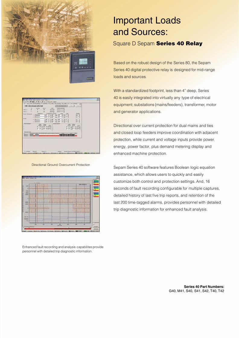
Based on the robust design o the Series 80, the Sepam
Series 40 digital protective relay is designed or mid-range
loads and sources.
With a standardized ootprint, less than 4” deep, Series
40 is easily integrated into virtually any type o electrical
equipment; substations (mains/eeders), transormer, motor
and generator applications.
Directional over current protection or dual mains and ties
and closed loop eeders improve coordination with adjacent
protection, while current and voltage inputs provide power,
energy, power actor, plus demand metering display and
enhanced machine protection.
Sepam Series 40 sotware eatures Boolean logic equation
assistance, which allows users to quickly and easily
customize both control and protection settings. And, 16
seconds o ault recording congurable or multiple captures,
detailed history o last ve trip reports, and retention o the
last 200 time-tagged alarms, provides personnel with detailed
trip diagnostic inormation or enhanced ault analysis.
Important Loads
and Sources:Square D Sepam Series 40 Relay
Series 40 Part Numbers
G40, M41, S40, S41, S42, T40, T42
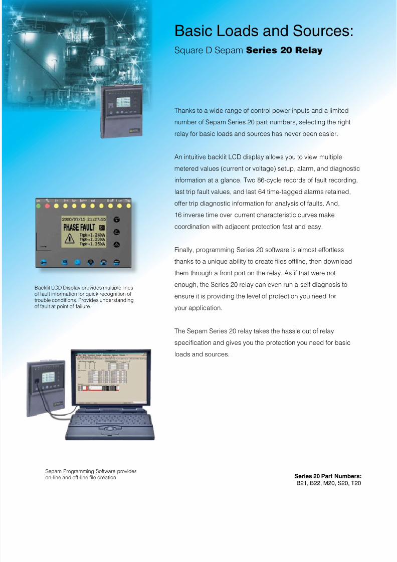
Enhanced ault recording and analysis capabilites provide
personnel with detailed trip diagnostic inormation.
Directional Ground Overcurrent Protection
8/3/2019 Spam Series
http://slidepdf.com/reader/full/spam-series 8/12
Basic Loads and Sources:Square D Sepam Series 20 Relay
Thanks to a wide range o control power inputs and a limited
number o Sepam Series 20 part numbers, selecting the right
relay or basic loads and sources has never been easier.
An intuitive backlit LCD display allows you to view multiple
metered values (current or voltage) setup, alarm, and diagnostic
inormation at a glance. Two 86-cycle records o ault recording,
last trip ault values, and last 64 time-tagged alarms retained,
oer trip diagnostic inormation or analysis o aults. And,
16 inverse time over current characteristic curves make
coordination with adjacent protection ast and easy.
Finally, programming Series 20 sotware is almost eortless
thanks to a unique ability to create les ofine, then download
them through a ront port on the relay. As i that were not
enough, the Series 20 relay can even run a sel diagnosis to
ensure it is providing the level o protection you need or
your application.
The Sepam Series 20 relay takes the hassle out o relay
specication and gives you the protection you need or basic
loads and sources.
Series 20 Part Numbers:
B21, B22, M20, S20, T20
Sepam Programming Sotware provideson-line and o-line le creation
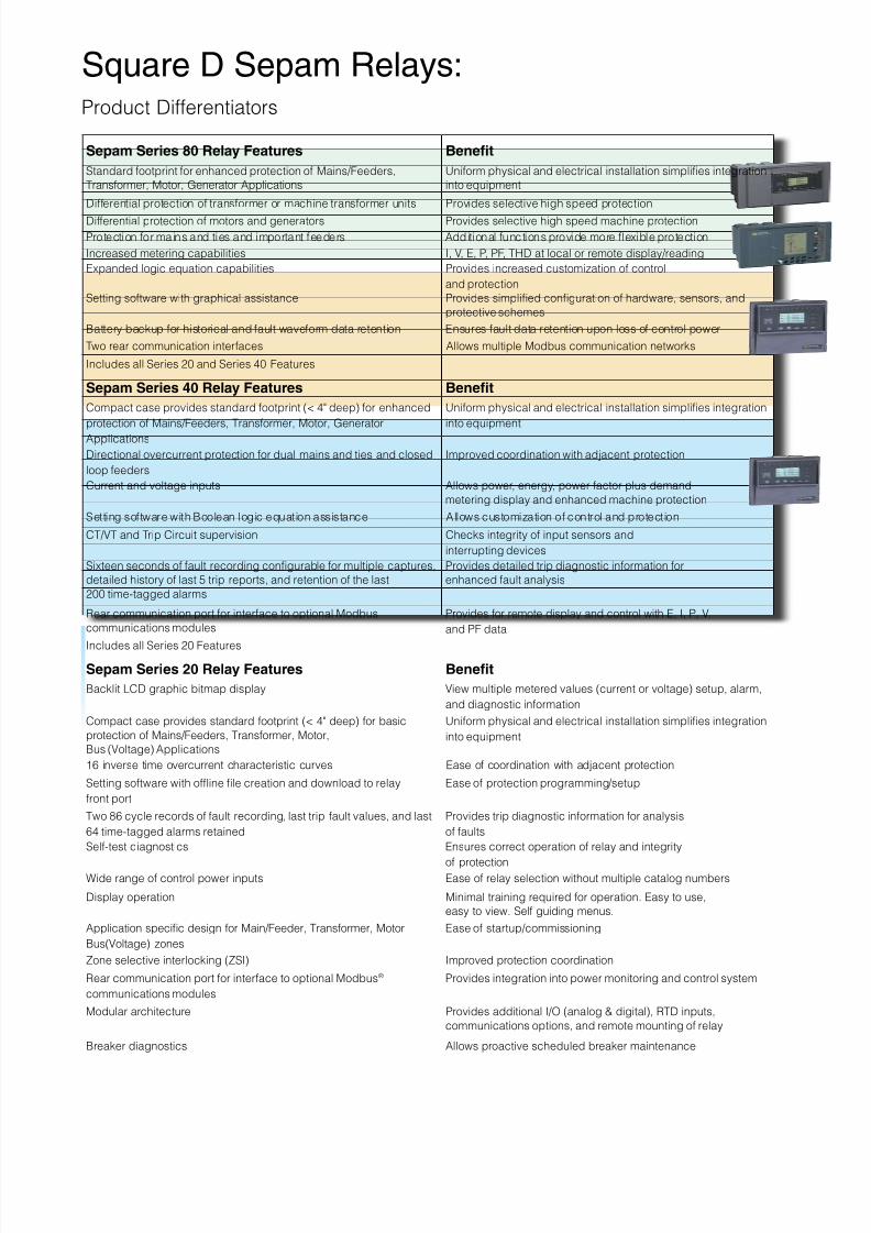
Backlit LCD Display provides multiple lines
o ault inormation or quick recognition otrouble conditions. Provides understandingo ault at point o ailure.
8/3/2019 Spam Series
http://slidepdf.com/reader/full/spam-series 9/12
Sepam Series 80 Relay Features Beneft
Standard ootprint or enhanced protection o Mains/Feeders,
Transormer, Motor, Generator Applications
Uniorm physical and electrical installation simplies integration
into equipment
Dierential protection o transormer or machine transormer units Provides selective high speed protection
Dierential protection o motors and generators Provides selective high speed machine protection
Protection or mains and ties and important eeders Additional unctions provide more fexible protection
Increased metering capabilities I, V, E, P, PF, THD at local or remote display/reading
Expanded logic equation capabilities Provides increased customization o control
and protection
Setting sotware with graphical assistance Provides simplied conguration o hardware, sensors, and
protective schemes
Battery backup or historical and ault waveorm data retention Ensures ault data retention upon loss o control power
Two rear communication interaces Allows multiple Modbus communication networks
Includes all Series 20 and Series 40 Features
Sepam Series 40 Relay Features Beneft
Compact case provides standard ootprint (< 4" deep) or enhanced
protection o Mains/Feeders, Transormer, Motor, Generator
Applications
Uniorm physical and electrical installation simplies integration
into equipment
Directional overcurrent protection or dual mains and ties and closed
loop eeders
Improved coordination with adjacent protection
Current and voltage inputs Allows power, energy, power actor plus demand
metering display and enhanced machine protection
Setting sotware with Boolean logic equation assistance Allows customization o control and protection
CT/VT and Trip Circuit supervision Checks integrity o input sensors and
interrupting devices
Sixteen seconds o ault recording congurable or multiple captures,
detailed history o last 5 trip reports, and retention o the last
200 time-tagged alarms
Provides detailed trip diagnostic inormation or
enhanced ault analysis
Rear communication port or interace to optional Modbus
communications modules
Provides or remote display and control with E, I, P, V,
and PF data
Includes all Series 20 Features
Sepam Series 20 Relay Features Beneft
Backlit LCD graphic bitmap display View multiple metered values (current or voltage) setup, alarm,
and diagnostic inormation
Compact case provides standard ootprint (< 4" deep) or basic
protection o Mains/Feeders, Transormer, Motor,
Bus (Voltage) Applications
Uniorm physical and electrical installation simplies integration
into equipment
16 inverse time overcurrent characteristic curves Ease o coordination with adjacent protection
Setting sotware with ofine le creation and download to relay
ront port
Ease o protection programming/setup
Two 86 cycle records o ault recording, last trip ault values, and last
64 time-tagged alarms retained
Provides trip diagnostic inormation or analysis
o aults
Sel-test diagnostics Ensures correct operation o relay and integrity
o protectionWide range o control power inputs Ease o relay selection without multiple catalog numbers
Display operation Minimal training required or operation. Easy to use,
easy to view. Sel guiding menus.
Application specic design or Main/Feeder, Transormer, Motor,
Bus(Voltage) zones
Ease o startup/commissioning
Zone selective interlocking (ZSI) Improved protection coordination
Rear communication port or interace to optional Modbus®
communications modules
Provides integration into power monitoring and control system
Modular architecture Provides additional I/O (analog & digital), RTD inputs,
communications options, and remote mounting o relay
Breaker diagnostics Allows proactive scheduled breaker maintenance
Square D Sepam Relays: Product Dierentiators
8/3/2019 Spam Series
http://slidepdf.com/reader/full/spam-series 10/12
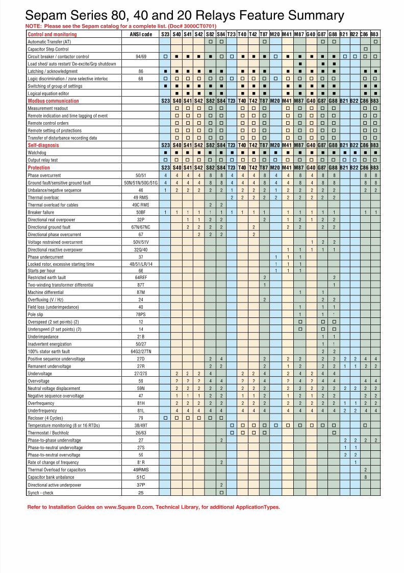
Sepam Series 80, 40 and 20 Relays Feature Summary
Reer to Installation Guides on www.Square D.com, Technical Library, or additional ApplicationTypes.
Control and monitoring ANSI code S23 S40 S41 S42 S82 S84 T23 T40 T42 T87 M20 M41 M87 G40 G87 G88 B21 B22 C86 B8
Automatic Transer (AT)
Capacitor Step Control
Circuit breaker / contactor control 94/69
Load shed/ auto restart/ De-excite/Grp shutdown
Latching / acknowledgment 86
Logic discrimination / zone selective interloc 68
Switching o group o settings
Logical equation editor
Modbus communication S23 S40 S41 S42 S82 S84 T23 T40 T42 T87 M20 M41 M87 G40 G87 G88 B21 B22 C86 B8Measurement readout
Remote indication and time tagging o event
Remote control orders
Remote setting o protections
Transer o disturbance recording data
Self-diagnosis S23 S40 S41 S42 S82 S84 T23 T40 T42 T87 M20 M41 M87 G40 G87 G88 B21 B22 C86 B8
Watchdog
Output relay test
Protection S23 S40 S41 S42 S82 S84 T23 T40 T42 T87 M20 M41 M87 G40 G87 G88 B21 B22 C86 B8
Phase overcurrent 50/51 4 4 4 4 8 8 4 4 4 8 4 4 8 4 8 8 8 8
Ground ault/sensitive ground ault 50N/51N/50G/51G 4 4 4 4 8 8 4 4 4 8 4 4 8 4 8 8 8 8
Unbalance/negative sequence 46 1 2 2 2 2 2 1 2 2 2 1 2 2 2 2 2 2 2
Thermal overload 49 RMS 2 2 2 2 2 2 2 2 2 2
Thermal overload or cables 49C RMS 2 2
Breaker ailure 50BF 1 1 1 1 1 1 1 1 1 1 1 1 1 1 1 1 1
Directional real overpower 32P 1 1 2 2 2 1 2 1 2 2
Directional ground ault 67N/67NC 2 2 2 2 2 2 2 2 2
Directional phase overcurrent 67 2 2 2 2
Voltage restrained overcurrent 50V/51V 1 2 2
Directional reactive overpower 32Q/40 1 1 1 1 1
Phase undercurrent 37 1 1 1
Locked rotor, excessive starting time 48/51/LR/14 1 1 1
Starts per hour 66 1 1 1
Restricted earth ault 64REF 2 2
Two-winding transormer dierential 87T 1 1
Machine dierential 87M 1 1
Overfuxing (V / Hz) 24 2 2 2Field loss (underimpedance) 40 1 1 1
Pole slip 78PS 1 1 1
Overspeed (2 set points) (2) 12
Underspeed (2 set points) (2) 14
Underimpedance 21B 1 1
Inadvertent energization 50/27 1 1
100% stator earth ault 64G2/27TN 2 2
Positive sequence undervoltage 27D 2 4 2 2 2 2 2 2 2 4 4
Remanent undervoltage 27R 2 2 2 1 2 2 2 1 1 2 2
Undervoltage 27/27S 2 2 2 4 2 2 4 2 4 2 4 4
Overvoltage 59 2 2 2 4 4 2 2 4 2 4 2 4 4 4 4
Neutral voltage displacement 59N 2 2 2 2 2 2 2 2 2 2 2 2 2 2 2 2 2
Negative sequence overvoltage 47 1 1 1 2 2 1 1 2 1 2 1 2 2 2 2
Overrequency 81H 2 2 2 2 2 2 2 2 2 2 2 2 2 1 1 2 2
Underrequency 81L 4 4 4 4 4 4 4 4 4 4 4 4 4 2 2 4 4
Recloser (4 Cycles) 79
Temperature monitoring (8 or 16 RTDs) 38/49T
Thermostat / Buchholz 26/63
Phase-to-phase undervoltage 27 2 2 2 2 2
Phase-to-neutral undervoltage 27S 1 1
Phase-to-neutral overvoltage 59 2 2
Rate o change o requency 81R 2 1
Thermal Overload or capacitors 49RMS 2
Capacitor bank unbalance 51C 8
Directional active underpower 37P 2
Synch - check 25
NOTE: Please see the Sepam catalog or a complete list. (Doc# 3000CT0701)
8/3/2019 Spam Series
http://slidepdf.com/reader/full/spam-series 11/12
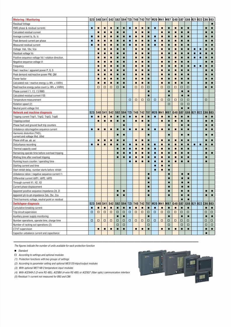
The fgures indicate the number o units available or each protection unction
Standard
According to settings and optional modules
(1) Protection unctions with two groups o settings
(2) According to parameter setting and optional MES120 intput/output modules
(3) With optional MET148-2 temperature input modules
(4) With ACE949-2 (2-wire RS 485), ACE959 (4-wire RS 485) or ACE937 (fber optic) communication interace
(5) Residual I'r current not measured or B83 and C86
Metering / Monitoring S23 S40 S41 S42 S82 S84 T23 T40 T42 T87 M20 M41 M87 G40 G87 G88 B21 B22 C86 B83
Residual Voltage
RMS phase & residual currents
Calculated residual current
Average current Ia, Ib, Ic
Peak demand current per phase
Measured residual current
Voltage Vab, Vbc, Vca
Residual voltage Vo
Positive sequence voltage Vd / rotation direction,
Negative sequence voltage Vi
Frequency
Real / reactive / apparent power P, Q, S
Peak demand real/reactive power PM, QM
Power actor
Calculated real / reactive energy (± Wh, ± VARh)
Real/reactive energy pulse count (± Wh, ± VARH)
Phase current I'1, I'2, I'3 RMS
Calculated residual current I‘0S
Temperature measurement
Rotation speed (2)
Neutral point voltage Vnt
Network and machine diagnosis S23 S40 S41 S42 S82 S84 T23 T40 T42 T87 M20 M41 M87 G40 G87 G88 B21 B22 C86 B83
Tripping current TripI1, TripI2, TripI3, Tripl0
Tripping context
Phase ault and ground ault trip counters
Unbalance ratio/negative sequence current
Harmonic distortion (THD),current and voltage Ithd, Uthd
Phase shit φa, φb, φc
Disturbance recording
Thermal capacity used
Remaining operate time beore overload tripping
Waiting time ater overload tripping
Running hours counter / operating time
Starting current and time
Start inhibit delay, number starts beore inhibit
Unbalance ration / negative sequence current I‘i
Dierential current Idi1, Idi2, Idi3
Through current It1, It2, It3
Current phase displacement
Apparent positive sequence impedance Zd, Zi
Apparent ph-to-ph impedance Zab, Zbc, Zca
Third harmonic voltage, neutral point or residual
Switchgear diagnosis S23 S40 S41 S42 S82 S84 T23 T40 T42 T87 M20 M41 M87 G40 G87 G88 B21 B22 C86 B83
Cumulative breaking current
Trip circuit supervision
Auxiliary power supply monitoring
Number operations, operate time, charge time
Number o racking out operations (2)
CT/VT supervision
Capacitor unbalance current and capacitance
8/3/2019 Spam Series
http://slidepdf.com/reader/full/spam-series 12/12