sparc 7 value will end up in the field of the resulting ... · the notations given in this section...
TRANSCRIPT

Rev. 4168C–AERO–08/01
1
Assembly Language SyntaxThe notations given in this section are taken from Sun’s SPARC Assembler and areused to describe the suggested assembly language syntax for the instruction defini-tions explained on page 5.
Understanding the use of type fonts is crucial to understanding the assembly lan-guage syntax in the instruction definitions. Items in typewriterfont are literals, to beentered exactly as they appear. Items in italic font are metasymbols that are to bereplaced by numeric or symbolic values when actual assembly language code is writ-ten. For example, asi would be replaced by a number in the range of 0 to 255 (thevalue of the bits in the binary instruction), or by a symbol that has been bound to sucha number.
Subscripts on metasymbols further identify the placement of the operand in the gener-ated binary instruction. For example, regrs2 is a reg (i.e., register name) whose binaryvalue will end up in the rs2 field of the resulting instruction.
SPARC 7Instruction Set

2
SPARC4168C–AERO–08/01
Register Names
reg A reg is an integer unit register. It can have a value of:
Subscripts further identify the placement of the operand in the binary instruction as oneof the following:
fregA freg is a floating-point register. It can have a value from %f0 through %f31. Subscriptsfurther identify the placement of the operand in the binary instruction as one of thefollowing:
creg A creg is a coprocessor register. It can have a value from %c0 through %c31. Sub-scripts further identify the placement of the operand in the binary instruction as one ofthe following:
Special Symbol Names
Certain special symbols need to be written exactly as they appear in the syntax table.These appear in typewriter font, and are preceded by a percent sign (%). The percentsign is part of the symbol name; it must appear as part of the literal value.
The symbol names are:
%0 through %31 all integer registers
%g0 through %g7 global registers—same as %0 through %7
%o0 through %o7 out registers—same as %8 through %15
%l0 through %l7 local registers—same as %16 through %23
%i0 through %i7 in registers—same as %24 through %31
regrs1 —rs1 field
regrs2 —rs2 field
regrd —rd field
fregrs1 —rs1 field
fregrs2 —rs2 field
fregrd —rd field
cregrs1 —rs1 field
cregrs2 —rs2 field
cregrd —rd field
%psr Processor State Register
%wim Window Invalid Mask register
%tbr Trap Base Register

3
SPARC
4168C–AERO–08/01
Values
Some instructions use operands comprising values as follows:
simm13—A signed immediate constant that fits in 13 bitsconst22—A constant that fits in 22 bitsasi—An alternate address space identifier (0 to 255)
Label
A label is a sequence of characters comprised of alphabetic letters (a-z, A-Z (upper andlower case distinct)), underscore (_), dollar sign ($), period (.), and decimal digits (0-9),but which does not begin with a decimal digit.
Some instructions offer a choice of operands. These are grouped as follows:regaddr:
regrs1regrs1 + regrs2
address:
regrs1regrs1 + regrs2regrs1 + simm13regrs1 - simm13simm13simm13 + regrs1
reg_or_imm:
regrs1simm13
Instruction Mnemonics
Figure 1. illustrates the mnemonics used to describe the SPARC instruction set. Notethat some combinations possible in Figure 1. do not correspond to valid instructions(such as store signed or floating-point convert extended to extended). Refer to theinstruction summary on PageBreak 7 for a list of valid SPARC instructions.
%y Y register
%fsr Floating-point State Register
%csr Coprocessor State Register
%fq Floating-point Queue
%cq Coprocessor Queue
%hi Unary operator that extracts high 22 bits of its operand
%lo Unary operator that extracts low 10 bits of its operand

4
SPARC4168C–AERO–08/01
Figure 1. SPARC Instruction Mnemonic Summary
Data Transfer
LoaDSTore
SignedUnsigned
singleDouble
Byte HalfwordwordDoubleword
Floating-pointCoprocessor
normalAlternate
register Status Register Queue
Integer Operations
AND ORXOR
normal Not
normal set CC Shift
Left Right
Logical Arithmetic
ADD SUB
normal eXtended
normal set CC Tagged
ADD SUB set CC
normal Trap oVerflow
ReaD WRite
Y PSRWIMTBR
MULtiply Step set CC SETHISAVERESTORE
Floating-Point Operations
Control Transfer
Fp convert
Integer Sin-gleDoubleeXtended TO
Fp
MOVe NEGateABSolute Single
Fp
ADD SUBtractMULtiplyDIVideSQuare RooTCoMPareCoMPare and Exception
Single DoubleeXtended
Integer SingleDoubleeXtended
Integer CC Floating-point CCCoprocessor CCBranch
normal Anull delay instruction CALL
Trap on Integer CC
JuMP and Link RETurn from Trap
atomic SWAP word atomic Load-Store Unsigned Byte

5
SPARC
4168C–AERO–08/01
DefinitionsThis section provides a detailed definition for each ERC 32 instruction. Each definitionincludes: the instruction operation; suggested assembly language syntax; a descriptionof the salient features, restrictions and trap conditions; a list of synchronous or floating-point\coprocessor traps which can occur as a consequence of executing the instruction;and the instruction format and op codes. Instructions are defined in alphabetical orderwith the instruction mnemonic shown in large bold type at the top of the PageBreak foreasy reference. The instruction set summary that precedes the definitions, (Table 2),groups the instructions by type.
Table 1. identifies the abbreviations and symbols used in the instruction definitions. Anexample of how some of the description notations are used is given below in Figure 2.Register names, labels and other aspects of the syntax used in these instructions aredescribed in the previous section.
Figure 2. Instruction Description
LDD Load Doubleword Operation : r[rd] [r[rs1] + (r[rs2] or sign_extend(simm13))]
r[rd + 1] [(r[rs1] + (r[rs2] or sign_extend(simm13))) + 4]
Assembler Syntax : ldd [address], regrd
Load data into destination register rdContents of source register 1
Contents of source register 2
An example of this instruction would be :ldd [%g1 + 4], %6which would add the contents of global register g1 to signed immediate value (4) to determine the load address. The resulting address is used to fetch and load doubleword data into the destination registers 6 and 7.
Sign-extended immediate 13-bit field of instruction
Brackets indicate data located at address specified by contents
Description :The LDD instruction moves a doubleword from memory into a destination register pair, r[rd] and r[rd+1]. The effective memory address is derived by summing the contents of r[rs1] and either the....

6
SPARC4168C–AERO–08/01
Table 1. Instruction Description NotationsSymbol Description
a Instruction field that controls instruction annulling during control transfers
AND, OR XOR, etc. AND, OR, XOR, etc operators
asr_reg Any implemented ASR (Ancillary State )
c The icc carry bit
ccc The coprocessor condition code field of the CCSR
CONCAT Concatenate
cond Instruction field that selects the condition code test for branches
creg Communication Coprocessor Register : can be %ccsr, %ccfr, %ccpr, %cccrc
CWP PSR‘s Current Window Pointer field
disp22 Instruction field that contains the 22-bit sign-extended displacement for branches
ET PSR‘s Enable Traps bit
i Instruction field that selects rs2 or sign_extend(simm13) as the second operand
icc The integer condition code field of the PSR
imm22 Instruction field that contains the 22-bit constant used by SETHI
n The icc negative bit
not Logical complement operator
nPC next Program Counter
opc Instruction field that specifies the count for Coprocessor-operate instructions
operand2 Either r[rs2] or sign_extend(simm13)
PC Program Counter
pS PSR‘s previous Supervisor bit
PSR Processor State Register
r[15] A directly addressed register (could be floating-point or coprocessor)
rd Instruction field that specifies the destination register (except for store)
r[rd]Depending on context, the integer register (or its contents) specified by the instruction field, e.g. , rd, rs1, rs2
r[rd]<31> <> are used to specify bit fields of a particular register or I/O signal
[r[rs1] + r[rs2]] The contents of the address specified by r[rs1] + r[rs2]
rs1 Instruction field that specifies the source 1 register
rs2 Instruction field that specifies the source 2 register
S PSR‘s Supervisor bit
shcnt Instruction field that specifies the count for shift instructions
sign_extend(simm13) Instruction field that contains the 13-bit, sign-extended immediate value
Symbol Description
TBR Trap Base Register
tt TBR‘s trap type field
uf Floating-point exception : underflow
v The icc overflow bit

7
SPARC
4168C–AERO–08/01
Symbol Description
WIM Window Invalid Mask register
Y Y Register
z The icc zero bit
- Subtract
x Multiply
/ Divide
<-- Replaced by
7FFFFFF H Hexadecimal number representation
+ Add

8
SPARC4168C–AERO–08/01
Table 2. Instruction Set SummaryName Operation
LDSB(LDSBA*)LDSH(LDSHA*)LDUB(LDUBA*)LDUH(LDUHA*)LD(LDA*)LDD(LDDA*)LDFLDDFLDFSRLDCLDDCLDCSRSTB(STBA*)STH(STHA*)ST(STA*)STD(STDA*)STFSTDFSTFSRSTDFQ*STCSTDCSTCSRSTDCQ*LDSTUB(LDSTUBA*)SWAP(SWAPA*)ADD(ADDcc)ADDX(ADDXcc)TADDcc(TADDccTV)SUB(SUBcc)SUBX(SUBXcc)TSUBcc(TSUBccTV)MULSccAND(ANDcc)ANDN(ANDNcc)OR(ORcc)ORN(ORNcc)XOR(XORcc)XNOR(XNORcc)SLLSRLSRASETHISAVERESTOREBiccFBiccCBcccCALL
Load Signed ByteLoad Signed HalfwordLoad Unsigned Byte
(from Alternate Space)
Load Unsigned HalfwordLoad WordLoad Doubleword
(from Alternate Space)
Load Floating PointLoad Double Floating PointLoad Floating Point StateRegisterLoad CoprocessorLoad Double CoprocessorLoad Coprocessor State RegisterStore ByteStore HalfwordStore WordStore Doubleword
(into Alternate Space)(into Alternate Space)(into Alternate Space)(into Alternate Space)
Store Floating PointStore Double Floating PointStore Floating Point State RegisterStore Double Floating Point Queue
Store CoprocessorStore Double CoprocessorStore Coprocessor State RegisterStore Double Coprocessor QueueAtomic Load/Store Unsigned ByteSwap r Register with Memory
(in Alternate Space)(in Alternate Space)
AddAdd with Carry
(and modify icc)(and modify icc)
Tagged Add and modify icc (and Trap on overflow)
Tagged Subtract and modify icc (and Trap on overflow)
SubtractSubtract with Carry
(and modify icc)(and modify icc)
Multiply Step and modifyiccAndAnd NotInclusive OrInclusive Or NotExclusive OrExclusive Nor
(and modify icc)(and modify icc)(and modify icc)(and modify icc)(and modify icc)(and modify icc)
Shift Left LogicalShift Right LogicalShift Right ArithmeticSet High 22 Bits of r RegisterSave caller’s windowRestore caller’s windowBranch on Integer Condition CodesBranch on Floating PointCondition CodesBranch on Coprocessor Condition CodesCall
(from Alternate Space)(from Alternate Space)
(from Alternate Space)
Cycles
22222323223233343434
34344411111111111111111111**1**1**1**
JMPLRETTTiccRDYRDPSR*RDWIM*RDTBR*WRYWRPSR*WRWIM*WRTBR*UNIMPIFLUSHFPopCPop
Jump and LinkReturn from TrapTrap on Integer Condition CodesRead Y RegisterRead Processor State RegisterRead Window Invalid MaskRead Trap Base RegisterWrite Y RegisterWrite Processor State RegisterWrite Window Invalid MaskWrite Trap Base RegisterUnimplemented InstructionInstruction Cache FlushFloating Point Unit Operations Coprocessor Operations
2**2**
1111111111
* privileged instruction ** assuming delay slot is filled with useful instruction
(from Alternate Space)
Lo
ad a
nd
Sto
re In
stru
ctio
ns
Ari
thm
etic
/Lo
gic
al/S
hif
tC
on
tro
lT
ran
sfer
Rea
d/W
rite
Co
ntr
ol R
egis
ters
Op
s
FP
(CP
)
1 (4 if Taken)
1 to Launch1 to Launch

9
SPARC
4168C–AERO–08/01
ADD Add
Operation: r[rd] r[rs1] + (r[rs2] or sign extnd(simm13))
Assembler Syntax:
add regrs1, reg_or_imm, regrd
Description: The ADD instruction adds the contents of the register named in the rs1 field ,r[rs1], toeither the contents of r[rs2] if the instruction’s i bit equals zero, or to the 13-bit, sign-extended immediate operand contained in the instruction if i equals one. The result isplaced in the register specified in the rd field.
Traps: none
Format:
1 0 rd 000 000 rs1 i=0 ignored rs2
31 30 29 25 24 19 18 14 13 12 5 4 0
31 30 29 25 24 19 18 14 13 12 0
1 0 rd 000 000 rs1 i=1 simm13

10
SPARC4168C–AERO–08/01
ADDcc Add and modify icc
Operation: r[rd] r[rs1] + operand2, where operand2 = (r[rs2] or sign extnd(simm13))n r[rd]<31>z if r[rd] =0 then 1, else 0v (r[rs1]<31> AND operand2<31> AND not r[rd]<31>)
OR (not r[rs1]<31> AND not operand2<31> AND r[rd]<31>)c (r[rs1]<31> AND operand2<31>)
OR (not r[rd]<31> AND (r[rs1]<31> OR operand2<31>))
Assembler Syntax:
addcc regrs1, reg_or_imm, regrd
Description: ADDcc adds the contents of r[rs1] to either the contents of r[rs2] if the instruction’s i bitequals zero, or to a 13-bit, sign-extended immediate operand if i equals one. The resultis placed in the register specified in the rd field. In addition, ADDcc modifies all the inte-ger condition codes in the manner described above.
Traps: none
Format:
31 30 29 25 24 19 18 14 13 12 5 4 0
1 0 rd 0 1 0 0 0 0 rs1 rs2ignoredi=0
31 30 29 25 24 19 18 14 13 12 0
rd rs1 simm13i=11 0 0 1 0 0 0 0

11
SPARC
4168C–AERO–08/01
ADDX Add with Carry
Operation: r[rd] r[rs1] + (r[rs2] or sign extnd(simm13)) + c
Assembler Syntax:
addx regrs1, reg_or_imm, regrd
Description: ADDX adds the contents of r[rs1] to either the contents of r[rs2] if the instruction’s i bitequals zero, or to a 13-bit, sign-extended immediate operand if i equals one. It thenadds the PSR’s carry bit (c) to that result. The final result is placed in the register spec-ified in the rd field.
Traps: none
Format:
31 30 29 25 24 19 18 14 13 12 5 4 0
1 0 rd 0 0 1 0 0 0 rs1 rs2ignoredi=0
31 30 29 25 24 19 18 14 13 12 0
rd rs1 simm13i=11 0 0 0 1 0 0 0

12
SPARC4168C–AERO–08/01
ADDXcc Add with Carry and modify icc
Operation: r[rd] r[rs1] + operand2 + c, where operand2 = (r[rs2] or sign extnd(simm13))n r[rd]<31>z if r[rd] =0 then 1, else 0v (r[rs1]<31> AND operand2<31> AND not r[rd]<31>)
OR (not r[rs1]<31> AND not operand2<31> AND r[rd]<31>)c (r[rs1]<31> AND operand2<31>)
OR (not r[rd]<31> AND (r[rs1]<31> OR operand2<31>))
Assembler Syntax:
addxcc regrs1, reg_or_imm, regrd
Description: ADDXcc adds the contents of r[rs1] to either the contents of r[rs2] if the instruction’s i bitequals zero, or to a 13-bit, sign-extended immediate operand if i equals one. It thenadds the PSR’s carry bit (c) to that result. The final result is placed in the register spec-ified in the rd field. ADDXcc also modifies all the integer condition codes in the mannerdescribed above.
Traps: none
Format:31 30 29 25 24 19 18 14 13 12 5 4 0
1 0 rd 0 1 1 0 0 0 rs1 rs2ignoredi=0
31 30 29 25 24 19 18 14 13 12 0
rd rs1 simm13i=11 0 0 1 1 0 0 0

13
SPARC
4168C–AERO–08/01
AND And
Operation: r[rd] r[rs1] AND (r[rs2] or sign extnd(simm13))
Assembler Syntax:
and regrs1, reg_or_imm, regrd
Description: This instruction does a bitwise logical AND of the contents of register r[rs1] with eitherthe contents of r[rs2] (if if bit field i=0) or the 13-bit, sign-extended immediate value con-tained in the instruction (if if bit field i=1). The result is stored in register r[rd].
Traps: none
Format:31 30 29 25 24 19 18 14 13 12 5 4 0
1 0 rd 0 0 0 0 0 1 rs1 rs2ignoredi=0
31 30 29 25 24 19 18 14 13 12 0
rd rs1 simm13i=11 0 0 0 0 0 0 1

14
SPARC4168C–AERO–08/01
ANDcc And and modify icc
Operation: r[rd] r[rs1] AND (r[rs2] or sign extnd(simm13))n r[rd]<31>z if r[rd] =0 then 1, else 0v 0c 0
Assembler Syntax:
andcc regrs1, reg_or_imm, regrd
Description: This instruction does a bitwise logical AND of the contents of register r[rs1] with eitherthe contents of r[rs2] (if if bit field i=0) or the 13-bit, sign-extended immediate value con-tained in the instruction (if if bit field i=1). The result is stored in register r[rd]. ANDccalso modifies all the integer condition codes in the manner described above.
Traps: none
Format:31 30 29 25 24 19 18 14 13 12 5 4 0
1 0 rd 0 1 0 0 0 1 rs1 rs2ignoredi=0
31 30 29 25 24 19 18 14 13 12 0
rd rs1 simm13i=11 0 0 1 0 0 0 1

15
SPARC
4168C–AERO–08/01
ANDN And Not
Operation: r[rd] r[rs1] AND (r[rs2] or sign extnd(simm13))
Assembler Syntax:
andn regrs1, reg_or_imm, regrd
Description: ANDN does a bitwise logical AND of the contents of register r[rs1] with the logical com-pliment (not) of either r[rs2] (if if bit field i=0) or the 13-bit, sign-extended immediatevalue contained in the instruction (if if bit field i=1). The result is stored in register r[rd].
Traps: none
Format:31 30 29 25 24 19 18 14 13 12 5 4 0
1 0 rd 0 0 0 1 0 1 rs1 rs2ignoredi=0
31 30 29 25 24 19 18 14 13 12 0
rd rs1 simm13i=11 0 0 0 0 1 0 1

16
SPARC4168C–AERO–08/01
ANDNcc And Not and modify icc
Operation: r[rd] r[rs1] AND (r[rs2] or sign extnd(simm13))n r[rd]<31>z if r[rd] =0 then 1, else 0v 0c 0
Assembler Syntax:
andncc regrs1, reg_or_imm, regrd
Description: ANDNcc does a bitwise logical AND of the contents of register r[rs1] with the logicalcompliment (not) of either r[rs2] (if bit field i=0) or the 13-bit, sign-extended immediatevalue contained in the instruction (if bit field i=1). The result is stored in register r[rd].ANDNcc also modifies all the integer condition codes in the manner described above.
Traps: none
Format:
31 30 29 25 24 19 18 14 13 12 5 4 0
1 0 rd 0 1 0 1 0 1 rs1 rs2ignoredi=0
31 30 29 25 24 19 18 14 13 12 0
rd rs1 simm13i=11 0 0 1 0 1 0 1

17
SPARC
4168C–AERO–08/01
Bicc Integer Conditional Branch
Operation: PC nPCIf condition true then nPC PC + (sign extnd(disp22) x 4)else nPC nPC + 4
Assembler Syntax:
ba{,a} label
bn{,a} labelbne{,a}labelsynonym: bnzbe{,a} labelsynonym: bzbg{,a} labelble{,a}labelbge{,a}abelbl{,a} labelbgu{,a}labelbleu{,a}labelbcc{,a}labelsynonym: bgeubcs{,a}labelsynonym: blubpos{,a}labelbneg{,a}labelbvc{,a}labelbvs{,a}label
Note: The instruction’s annul bit field, a, is set by appending “,a” after the branch name. If it isnot appended, the a field is automatically reset. “,a” is shown in braces because it isoptional.
Description: The Bicc instructions (except for BA and BN) evaluate specific integer condition codecombinations (from the PSR’s icc field) based on the branch type as specified by thevalue in the instruction’s cond field. If the specified combination of condition codes eval-uates as true, the branch is taken, causing a delayed, PC-relative control transfer to theaddress (PC + 4) + (sign extnd(disp22) x 4). If the condition codes evaluate as false, thebranch is not taken.
If the branch is not taken, the annul bit field (a) is checked. If a is set, the instructionimmediately following the branch instruction (the delay instruction) is not executed (i.e.,it is annulled). If the annul field is zero, the delay instruction is executed. If the branch istaken, the annul field is ignored, and the delay instruction is executed.
Branch Never (BN) executes like a NOP, except it obeys the annul field with respect toits delay instruction.
Branch Always (BA), because it always branches regardless of the condition codes,would normally ignore the annul field. Instead, it follows the same annul field rules: ifa=1, the delay instruction is annulled; if a=0, the delay instruction is executed.
The delay instruction following a Bicc (other than BA) should not be a delayed-control-transfer instruction. The results of following a Bicc with another delayed control transferinstruction are implementation-dependent and therefore unpredictable.

18
SPARC4168C–AERO–08/01
Traps: none
Format:
Mnemonic Cond. Operation icc Test
BN 0000 Branch Never No test
BE 0001 Branch on Equal z
BLE 0010 Branch on Less or Equal z OR (n XOR v)
BL 0011 Branch on Less n XOR v
BLEU 0100 Branch on Less or Equal, Unsigned c OR z
BCS 0101Branch on Carry Set (Less than, Unsigned)
c
BNEG 0110 Branch on Negative n
BVS 0111 Branch on oVerflow Set v
BA 1000 Branch Always No test
BNE 1001 Branch on Not Equal not z
BG 1010 Branch on Greater not(z OR (n XOR v))
BGE 1011 Branch on Greater or Equal not(n XOR v)
BGU 1100 Branch on Greater, Unsigned not(c OR z)
BCC 1101Branch on Carry Clear (Greater than or Equal, Unsigned)
not c
BPOS 1110 Branch on Positive not n
BVC 1111 Branch on oVerflow Clear not v
31 30 29 28 25 22 21 0
0 0 a 0 1 0 disp22
24
cond.

19
SPARC
4168C–AERO–08/01
CALL Call
Operation: r[15] PCPC nPCnPC PC + (disp30 x 4)
Assembler Syntax:
call label
Description: The CALL instruction causes a delayed, unconditional, PC-relative control transfer tothe address (PC + 4) + (disp30 x 4). The CALL instruction does not have an annul bit,therefore the delay slot instruction following the CALL instruction is always executed.CALL first writes its return address (PC) into the outs register, r[15], and then adds 4 tothe PC. The 32-bit displacement which is added to the new PC is formed by appendingtwo low-order zeros to the 30-bit word displacement contained in the instruction. Con-sequently, the target address can be anywhere in the ERC 32’s user or supervisoraddress space.
If the instruction following a CALL uses register r[15] as a source operand, hardwareinterlocks add a one cycle delay.
Programming note: a register-indirect CALL can be constructed using a JMPL instruc-tion with rd set to 15.
Traps: none
Format:
31 30 29 0
0 1 disp30

20
SPARC4168C–AERO–08/01
CBccc Coprocessor Conditional Branch
Operation: PC nPCIf condition true then nPC PC + (sign extnd(disp22) x 4)else nPC nPC + 4
Assembler Syntax:
cba{,a}label
cbn{,a}labelcb3{,a}abelcb2{,a}abelcb23{,a}labelcb1{,a}labelcb13{,a}labelcb12{,a}labelcb123{,a}labelcb0{,a}abelcb03{,a}labelcb02{,a}labelcb023{,a}labelcb01{,a}labelcb013{,a}labelcb012{,a}label
Note: The instruction’s annul bit field, a, is set by appending “,a” after the branch name. If it isnot appended, the a field is automatically reset. “,a” is shown in braces because it isoptional.
Description: The CBccc instructions (except for CBA and CBN) evaluate specific coprocessor condi-tion code combinations (from the CCC<1:0> inputs) based on the branch type asspecified by the value in the instruction’s cond field. If the specified combination of con-dition codes evaluates as true, the branch is taken, causing a delayed, PC-relativecontrol transfer to the address (PC + 4) + (sign extnd(disp22) x 4). If the condition codesevaluate as false, the branch is not taken.
If the branch is not taken, the annul bit field (a) is checked. If a is set, the instructionimmediately following the branch instruction (the delay instruction) is not executed (i.e.,it is annulled). If the annul field is zero, the delay instruction is executed. If the branch istaken, the annul field is ignored, and the delay instruction is executed.
Branch Never (CBN) executes like a NOP, except it obeys the annul field with respect toits delay instruction.
Branch Always (CBA), because it always branches regardless of the condition codes,would normally ignore the annul field. Instead, it follows the same annul field rules: ifa=1, the delay instruction is annulled; if a=0, the delay instruction is executed.
To prevent misapplication of the condition codes, a non-coprocessor instruction mustimmediately precede a CBccc instruction.
A CBccc instruction generates a cp_disabled trap (and does not branch or annul) if thePSR’s EC bit is reset or if no coprocessor is present.

21
SPARC
4168C–AERO–08/01
Traps: cp_disabled
cp_exception
Format:
Mnemonic cond. CCC<1:0> test
CBN 0000 Never
CB123 0001 1 or 2 or 3
CB12 0010 1 or 2
CB13 0011 1 or 3
CB1 0100 1
CB23 0101 2 or 3
CB2 0110 2
CB3 0111 3
CBA 1000 Always
CB0 1001 0
CB03 1010 0 or 3
CB02 1011 0 or 2
CB023 1100 0 or 2 or 3
CB01 1101 0 or 1
CB013 1110 0 or 1 or 3
CB012 1111 0 or 1 or 2
31 30 29 28 25 22 21 0
0 0 a 1 1 1 disp22
24
cond.

22
SPARC4168C–AERO–08/01
CPop Coprocessor Operate
Operation: Dependent on Coprocessor implementation
Assembler Syntax:
Unspecified
Description: CPop1 and CPop2 are the instruction formats for coprocessor operate instructions. Theop3 field for CPop1 is 110110; for CPop2 it’s 110111. The coprocessor operationsthemselves are encoded in the opc field and are dependent on the coprocessor imple-mentation. Note that this does not include load/store coprocessor instructions, whichfall into the integer unit’s load/store instruction category.
All CPop instructions take all operands from, and return all results to, the coprocessor’sregisters. The data types supported, how the operands are aligned, and whether aCPop generates a cp_exception trap are Coprocessor dependent.
A CPop instruction causes a cp_disabled trap if the PSR’s EC bit is reset or if no copro-cessor is present.
Traps: cp_disabledcp_exception
Format:31 30 29 25 24 19 18 14 13 5 4 0
1 0 rd 1 1 0 1 1 0 rs1 rs2opc
31 30 29 25 24 19 18 14 13 5 4 0
1 0 rd 1 1 0 1 1 1 rs1 rs2opc

23
SPARC
4168C–AERO–08/01
FABSs Absolute Value Single(FPU Instruction Only)
Operation: f[rd]s f[rs2]s AND 7FFFFFFF H
Assembler Syntax:
fabss fregrs2, fregrd
Description: The FABSs instruction clears the sign bit of the word in f[rs2] and places the result inf[rd]. It does not round.
Since rs2 can be either an even or odd register, FABSs can also operate on the high-order words of double and extended operands, which accomplishes sign bit clear forthese data types.
Traps: fp_disabledfp_exception*
Format:
Note: An attempt to execute any FP instruction will cause a pending FP exception to be recog-nized by the integer unit
31 30 29 25 24 19 18 14 13 5 4 0
1 0 rd 1 1 0 1 0 0 ignored rs20 0 0 0 0 1 0 0 1

24
SPARC4168C–AERO–08/01
FADDd Add Double(FPU Instruction Only)
Operation: f[rd]d f[rs1]d + f[rs2]d
Assembler Syntax:
faddd fregrs1, fregrs2, fregrd
Description: The FADDd instruction adds the contents of f[rs1] CONCAT f[rs1+1] to the contents off[rs2] CONCAT f[rs2+1] as specified by the ANSI/IEEE 754-1985 standard and placesthe results in f[rd] and f[rd+1].
Traps: fp_disabledfp_exception (of, uf, nv, nx)
Format:
31 30 29 25 24 19 18 14 13 5 4 0
1 0 rd 1 1 0 1 0 0 rs1 rs20 0 1 0 0 0 0 1 0

25
SPARC
4168C–AERO–08/01
FADDs Add Single(FPU Instruction Only)
Operation: f[rd]s f[rs1]s + f[rs2]s
Assembler Syntax:
fadds fregrs1, fregrs2, fregrd
Description: The FADDs instruction adds the contents of f[rs1] to the contents of f[rs2] as specifiedby the ANSI/IEEE 754-1985 standard and places the results in f[rd].
Traps: fp_disabledfp_exception (of, uf, nv, nx)
Format:
31 30 29 25 24 19 18 14 13 5 4 0
1 0 rd 1 1 0 1 0 0 rs1 rs20 0 1 0 0 0 0 0 1

26
SPARC4168C–AERO–08/01
FADDx Add Extended(FPU Instruction Only)
Operation: f[rd]x f[rs1]x + f[rs2]x
Assembler Syntax:
faddx fregrs1, fregrs2, fregrd
Description: The FADDx instruction adds the contents of f[rs1] CONCAT f[rs1+1] CONCAT f[rs1+2]to the contents of f[rs2] CONCAT f[rs2+1] CONCAT f[rs2+2] as specified by theANSI/IEEE 754-1985 standard and places the results in f[rd], f[rd+1], and f[rd+2].
Traps: fp_disabledfp_exception (of, uf, nv, nx)
Format:
31 30 29 25 24 19 18 14 13 5 4 0
1 0 rd 1 1 0 1 0 0 rs1 rs20 0 1 0 0 0 0 1 1

27
SPARC
4168C–AERO–08/01
FBfcc Floating-Point Conditional Branch
Operation: PC nPCIf condition true then nPC PC + (sign extnd(disp22) x 4)else nPC nPC + 4
Assembler Syntax:
fba{,a}label
fbn{,a}labelfbu{,a}labelfbg{,a}labelfbug{,a}labelfbl{,a} labelfbul{,a}labelfblg{,a}labelfbne{,a}labelsynonym: fbnzfbe{,a}labelsynonym: fbzfbue{,a}labelfbge{,a}labelfbuge{,a}labelfble{,a}labelfbule{,a}labelfbo{,a}label
Note: The instruction’s annul bit field, a, is set by appending “,a” after the branch name. If it isnot appended, the a field is automatically reset. “,a” is shown in braces because it isoptional.
Description: The FBfcc instructions (except for FBA and FBN) evaluate specific floating-point condi-tion code combinations (from the FCC<1:0> inputs) based on the branch type, asspecified by the value in the instruction’s cond field. If the specified combination of con-dition codes evaluates as true, the branch is taken, causing a delayed, PC-relativecontrol transfer to the address (PC + 4) + (sign extnd(disp22) x 4). If the condition codesevaluate as false, the branch is not taken.
If the branch is not taken, the annul bit field (a) is checked. If a is set, the instructionimmediately following the branch instruction (the delay instruction) is not executed (i.e.,it is annulled). If the annul field is zero, the delay instruction is executed. If the branch istaken, the annul field is ignored, and the delay instruction is executed.
Branch Never (FBN) executes like a NOP, except it obeys the annul field with respect toits delay instruction.
Branch Always (FBA), because it always branches regardless of the condition codes,would normally ignore the annul field. Instead, it follows the same annul field rules: ifa=1, the delay instruction is annulled; if a=0, the delay instruction is executed.
To prevent misapplication of the condition codes, a non-floating-point instruction mustimmediately precede an FBfcc instruction.
An FBfcc instruction generates an fp_disabled trap (and does not branch or annul) if thePSR’s EF bit is reset or if no Floating-Point Unit is present.

28
SPARC4168C–AERO–08/01
Traps: fp_disabledfp_exception*
Format:
Note: An attempt to execute any FP instruction will cause a pending FP exception to be recog-nized by the integer unit
Mnemonic Cond. Operation fcc Test
FBN 0000 Branch Never no test
FBNE 0001 Branch on Not Equal U or L or G
FBLG 0010 Branch on Less or Greater L or G
FBUL 0011 Branch on Unordered or Less U or L
FBL 0100 Branch on Less L
FBUG 0101 Branch on Unordered or Greater U or G
FBG 0110 Branch on Greater G
FBU 0111 Branch on Unordered U
FBA 1000 Branch Always no test
FBE 1001 Branch on Equal E
FBUE 1010 Branch on Unordered or Equal U or E
FBGE 1011 Branch on Greater or Equal G or E
FBUGE 1100Branch on Unordered or Greater or Equal
U or G or E
FBLE 1101 Branch on Less or Equal L or E
FBULE 1110Branch on Unordered or Less or Equal
U or L or E
FBO 1111 Branch on Ordered L or G or E
31 30 29 28 25 22 21 0
0 0 a 1 1 0 disp22
24
cond.

29
SPARC
4168C–AERO–08/01
FCMPd Compare Double(FPU Instruction Only)
Operation: fcc f[rs1]d COMPARE f[rs2]d
Assembler Syntax:
fcmpd fregrs1, fregrs2
Description: FCMPd subtracts the contents of f[rs2] CONCAT f[rs2+1] from the contents of f[rs1]CONCAT f[rs1+1] following the ANSI/IEEE 754-1985 standard. The result is evaluated,the FSR’s fcc bits are set accordingly, and then the result is discarded. The codes areset as follows:
In this table, fs1 stands for the contents of f[rs1], f[rs1+1] and fs2 represents the con-tents of f[rs2], f[rs2+1].
Compare instructions are used to set up the floating-point condition codes for a subse-quent FBfcc instruction. However, to prevent misapplication of the condition codes, atleast one non-floating-point instruction must be executed between an FCMP and a sub-sequent FBfcc instruction.
FCMPd causes an invalid exception (nv) if either operand is a signaling NaN.
Traps: fp_disabledfp_exception (nv)
Format:
fcc relation
0 fs1 = fs2
1 fs1 < fs2
2 fs1 > fs2
3 fs1 ? fs2 (unordered)
31 30 29 25 24 19 18 14 13 5 4 0
1 0 ignored 1 1 0 1 0 1 rs1 rs20 0 1 0 1 0 0 1 0

30
SPARC4168C–AERO–08/01
FCMPEd Compare Double and Exception if Unordered(FPU Instruction Only)
Operation: fcc f[rs1]d COMPARE f[rs2]d
Assembler Syntax:
fcmped fregrs1, fregrs2
Description: FCMPEd subtracts the contents of f[rs2] CONCAT f[rs2+1] from the contents of f[rs1]CONCAT f[rs1+1] following the ANSI/IEEE 754-1985 standard. The result is evaluated,the FSR’s fcc bits are set accordingly, and then the result is discarded. The codes areset as follows:
In this table, fs1 stands for the contents of f[rs1], f[rs1+1] and fs2 represents the con-tents of f[rs2], f[rs2+1].
Compare instructions are used to set up the floating-point condition codes for a subse-quent FBfcc instruction. However, to prevent misapplication of the condition codes, atleast one non-floating-point instruction must be executed between an FCMP and a sub-sequent FBfcc instruction.
FCMPEd causes an invalid exception (nv) if either operand is a signaling or quiet NaN.
Traps: fp_disabledfp_exception (nv)
Format:
fcc Relation
0 fs1 = fs2
1 fs1 < fs2
2 fs1 > fs2
3 fs1 ? fs2 (unordered)
31 30 29 25 24 19 18 14 13 5 4 0
1 0 ignored 1 1 0 1 0 1 rs1 rs20 0 1 0 1 0 1 1 0

31
SPARC
4168C–AERO–08/01
FCMPEs Compare Single and Exception if Unordered(FPU Instruction Only)
Operation: fcc f[rs1]s COMPARE f[rs2]s
Assembler Syntax:
fcmpes fregrs1, fregrs2
Description: FCMPEs subtracts the contents of f[rs2] from the contents of f[rs1] following theANSI/IEEE 754-1985 standard. The result is evaluated, the FSR’s fcc bits are setaccordingly, and then the result is discarded. The codes are set as follows:
In this table, fs1 stands for the contents of f[rs1] and fs2 represents the contents off[rs2].
Compare instructions are used to set up the floating-point condition codes for a subse-quent FBfcc instruction. However, to prevent misapplication of the condition codes, atleast one non-floating-point instruction must be executed between an FCMP and a sub-sequent FBfcc instruction.
FCMPEs causes an invalid exception (nv) if either operand is a signaling or quiet NaN.
Traps: fp_disabledfp_exception (nv)
Format:
fcc Relation
0 fs1 = fs2
1 fs1 < fs2
2 fs1 > fs2
3 fs1 ? fs2 (unordered)
31 30 29 25 24 19 18 14 13 5 4 0
1 0 ignored 1 1 0 1 0 1 rs1 rs20 0 1 0 1 0 1 0 1

32
SPARC4168C–AERO–08/01
FCMPEx Compare Extended and Exception if Unordered(FPU Instruction Only)
Operation: fcc f[rs1]x COMPARE f[rs2]x
Assembler Syntax:
fcmpex fregrs1, fregrs2
Description: FCMPEx subtracts the contents of f[rs2] CONCAT f[rs2+1] CONCAT f[rs2+2] from thecontents of f[rs1] CONCAT f[rs1+1] CONCAT f[rs1+2] following the ANSI/IEEE 754-1985 standard. The result is evaluated, the FSR’s fcc bits are set accordingly, and thenthe result is discarded. The codes are set as follows:
In this table, fs1 stands for the contents of f[rs1], f[rs1+1], f[rs1+2] and fs2 represents thecontents of f[rs2], f[rs2+1], f[rs2+2].
Compare instructions are used to set up the floating-point condition codes for a subse-quent FBfcc instruction. However, to prevent misapplication of the condition codes, atleast one non-floating-point instruction must be executed between an FCMP and a sub-sequent FBfcc instruction.
FCMPEx causes an invalid exception (nv) if either operand is a signaling or quiet NaN.
Traps: fp_disabledfp_exception (nv)
Format:
fcc Relation
0 fs1 = fs2
1 fs1 < fs2
2 fs1 > fs2
3 fs1 ? fs2 (unordered)
31 30 29 25 24 19 18 14 13 5 4 0
1 0 ignored 1 1 0 1 0 1 rs1 rs20 0 1 0 1 0 1 1 1

33
SPARC
4168C–AERO–08/01
FCMPs Compare Single(FPU Instruction Only)
Operation: fcc f[rs1]s COMPARE f[rs2]s
Assembler Syntax:
fcmps fregrs1, fregrs2
Description: FCMPs subtracts the contents of f[rs2] from the contents of f[rs1] following theANSI/IEEE 754-1985 standard. The result is evaluated, the FSR’s fcc bits are setaccordingly, and then the result is discarded. The codes are set as follows:
In this table, fs1 stands for the contents of f[rs1] and fs2 represents the contents off[rs2].
Compare instructions are used to set up the floating-point condition codes for a subse-quent FBfcc instruction. However, to prevent misapplication of the condition codes, atleast one non-floating-point instruction must be executed between an FCMP and a sub-sequent FBfcc instruction.
FCMPs causes an invalid exception (nv) if either operand is a signaling NaN.
Traps: fp_disabledfp_exception (nv)
Format:
fcc Relation
0 fs1 = fs2
1 fs1 < fs2
2 fs1 > fs2
3 fs1 ? fs2 (unordered)
31 30 29 25 24 19 18 14 13 5 4 0
1 1 ignored 1 1 0 1 0 1 rs1 rs20 0 1 0 1 0 0 0 1

34
SPARC4168C–AERO–08/01
FCMPx Compare Extended(FPU Instruction Only)
Operation: fcc f[rs1]x COMPARE f[rs2]x
Assembler Syntax:
fcmpx fregrs1, fregrs2
Description: FCMPx subtracts the contents of f[rs2] CONCAT f[rs2+1] CONCAT f[rs2+2] from thecontents of f[rs1] CONCAT f[rs1+1] CONCAT f[rs1+2] following the ANSI/IEEE 754-1985 standard. The result is evaluated, the FSR’s fcc bits are set accordingly, and thenthe result is discarded. The codes are set as follows:
In this table, fs1 stands for the contents of f[rs1], f[rs1+1], f[rs1+2] and fs2 represents thecontents of f[rs2], f[rs2+1], f[rs2+2].
Compare instructions are used to set up the floating-point condition codes for a subse-quent FBfcc instruction. However, to prevent misapplication of the condition codes, atleast one non-floating-point instruction must be executed between an FCMP and a sub-sequent FBfcc instruction.
FCMPx causes an invalid exception (nv) if either operand is a signaling NaN.
Traps: fp_disabledfp_exception (nv)
Format:
fcc Relation
0 fs1 = fs2
1 fs1 < fs2
2 fs1 > fs2
3 fs1 ? fs2 (unordered)
31 30 29 25 24 19 18 14 13 5 4 0
1 0 ignored 1 1 0 1 0 1 rs1 rs20 0 1 0 1 0 0 1 1

35
SPARC
4168C–AERO–08/01
FDIVd Divide Double(FPU Instruction Only)
Operation: f[rd]d f[rs1]d / f[rs2]d
Assembler Syntax:
fdivd fregrs1, fregrs2, fregrd
Description: The FDIVd instruction divides the contents of f[rs1] CONCAT f[rs1+1] by the contents off[rs2] CONCAT f[rs2+1] as specified by the ANSI/IEEE 754-1985 standard and placesthe results in f[rd] and f[rd+1].
Traps: fp_disabledfp_exception (of, uf, dz, nv, nx)
Format:
31 30 29 25 24 19 18 14 13 5 4 0
1 0 rd 1 1 0 1 0 0 rs1 rs20 0 1 0 0 1 1 1 0

36
SPARC4168C–AERO–08/01
FDIVs Divide Single(FPU Instruction Only)
Operation: f[rd]s f[rs1]s / f[rs2]s
Assembler Syntax:
fdivs fregrs1, fregrs2, fregrd
Description: The FDIVs instruction divides the contents of f[rs1] by the contents of f[rs2] as specifiedby the ANSI/IEEE 754-1985 standard and places the results in f[rd].
Traps: fp_disabled
fp_exception (of, uf, dz, nv, nx)
Format:
31 30 29 25 24 19 18 14 13 5 4 01 0 rd 1 1 0 1 0 0 rs1 rs20 0 1 0 0 1 1 0 1

37
SPARC
4168C–AERO–08/01
FDIVx Divide Extended(FPU Instruction Only)
Operation: f[rd]x f[rs1]x / f[rs2]x
Assembler Syntax:
fdivx fregrs1, fregrs2, fregrd
Description: The FDIVx instruction divides the contents of f[rs1] CONCAT f[rs1+1] CONCAT f[rs1+2]by the contents of f[rs2] CONCAT f[rs2+1] CONCAT f[rs2+2] as specified by theANSI/IEEE 754-1985 standard and places the results in f[rd], f[rd+1], and f[rd+2].
Traps: fp_disabledfp_exception (of, uf, dz, nv, nx)
Format:
31 30 29 25 24 19 18 14 13 5 4 0
1 0 rd 1 1 0 1 0 0 rs1 rs20 0 1 0 0 1 1 1 1

38
SPARC4168C–AERO–08/01
FdTOi Convert Double to Integer(FPU Instruction Only)
Operation: f[rd]i f[rs2]d
Assembler Syntax:
fdtoi fregrs2, fregrd
Description: FdTOi converts the floating-point double contents of f[rs2] CONCAT f[rs2+1] to a 32-bit,signed integer by rounding toward zero as specified by the ANSI/IEEE 754-1985 stan-dard. The result is placed in f[rd]. The rounding direction field (RD) of the FSR isignored.
Traps: fp_disabledfp_exception (nv, nx)
Format:
31 30 29 25 24 19 18 14 13 5 4 0
1 0 rd 1 1 0 1 0 0 ignored rs20 1 1 0 1 0 0 1 0

39
SPARC
4168C–AERO–08/01
FdTOs Convert Double to Single(FPU Instruction Only)
Operation: f[rd]s f[rs2]d
Assembler Syntax:
fdtos fregrs2, fregrd
Description: FdTOs converts the floating-point double contents of f[rs2] CONCAT f[rs2+1] to a single-precision, floating-point format as specified by the ANSI/IEEE 754-1985 standard. Theresult is placed in f[rd]. Rounding is performed according to the rounding direction field(RD) of the FSR.
Traps: fp_disabledfp_exception (of, uf, nv, nx)
Format:
31 30 29 25 24 19 18 14 13 5 4 0
1 0 rd 1 1 0 1 0 0 ignored rs20 1 1 0 0 0 1 1 0

40
SPARC4168C–AERO–08/01
FdTOx Convert Double to Extended(FPU Instruction Only)
Operation: f[rd]x f[rs2]d
Assembler Syntax:
fdtox fregrs2, fregrd
Description: FdTOx converts the floating-point double contents of f[rs2] CONCAT f[rs2+1] to anextended-precision, floating-point format as specified by the ANSI/IEEE 754-1985 stan-dard. The result is placed in f[rd], f[rd+1], and f[rd+2]. Rounding is performed accordingto the rounding direction (RD) and rounding precision (RP) fields of the FSR.
Traps: fp_disabledfp_exception (nv)
Format:
31 30 29 25 24 19 18 14 13 5 4 0
1 0 rd 1 1 0 1 0 0 ignored rs20 1 1 0 0 1 1 1 0

41
SPARC
4168C–AERO–08/01
FiTOd Convert Integer to Double(FPU Instruction Only)
Operation: f[rd]d f[rs2]i
Assembler Syntax:
fitod fregrs2, fregrd
Description: FiTOd converts the 32-bit, signed integer contents of f[rs2] to a floating-point, double-precision format as specified by the ANSI/IEEE 754-1985 standard. The result is placedin f[rd] and f[rd+1].
Traps: fp_disabledfp_exception*
Format:
31 30 29 25 24 19 18 14 13 5 4 0
1 0 rd 1 1 0 1 0 0 ignored rs20 1 1 0 0 1 0 0 0

42
SPARC4168C–AERO–08/01
FiTOs Convert Integer to Single(FPU Instruction Only)
Operation: f[rd]s f[rs2]i
Assembler Syntax:
fitos fregrs2, fregrd
Description: FiTOs converts the 32-bit, signed integer contents of f[rs2] to a floating-point, single-pre-cision format as specified by the ANSI/IEEE 754-1985 standard. The result is placed inf[rd]. Rounding is performed according to the rounding direction field, RD.
Traps: fp_disabledfp_exception (nx)
Format:
31 30 29 25 24 19 18 14 13 5 4 0
1 0 rd 1 1 0 1 0 0 ignored rs20 1 1 0 0 0 1 0 0

43
SPARC
4168C–AERO–08/01
FiTOx Convert Integer to Extended(FPU Instruction Only)
Operation: f[rd]x f[rs2]i
Assembler Syntax:
fitox fregrs2, fregrd
Description: FiTOx converts the 32-bit, signed integer contents of f[rs2] to an extended-precision,floating-point format as specified by the ANSI/IEEE 754-1985 standard. The result isplaced in f[rd], f[rd+1], and f[rd+2].
Traps: fp_disabledfp_exception*
Format:
Note: An attempt to execute any FP instruction will cause a pending FP exception to be recog-nized by the integer unit.
31 30 29 25 24 19 18 14 13 5 4 0
1 0 rd 1 1 0 1 0 0 ignored rs20 1 1 0 0 1 1 0 0

44
SPARC4168C–AERO–08/01
FMOVs Move(FPU Instruction Only)
Operation: f[rd]s f[rs2]s
Assembler Syntax:
fmovs fregrs2, fregrd
Description: The FMOVs instruction moves the word content of register f[rs2] to the register f[rd].Multiple FMOVs’s are required to transfer multiple-precision numbers between fregisters.
Traps: fp_disabledfp_exception*
Format:
Note: An attempt to execute any FP instruction will cause a pending FP exception to be recog-nized by the integer unit.
31 30 29 25 24 19 18 14 13 5 4 0
1 0 rd 1 1 0 1 0 0 ignored rs20 0 0 0 0 0 0 0 1

45
SPARC
4168C–AERO–08/01
FMULd Multiply Double(FPU Instruction Only)
Operation: f[rd]d f[rs1]d x f[rs2]d
Assembler Syntax:
fmuld fregrs1, fregrs2, fregrd
Description: The FMULd instruction multiplies the contents of f[rs1] CONCAT f[rs1+1] by the con-tents of f[rs2] CONCAT f[rs2+1] as specified by the ANSI/IEEE 754-1985 standard andplaces the results in f[rd] and f[rd+1].
Traps: fp_disabledfp_exception (of, uf, nv, nx)
Format:
31 30 29 25 24 19 18 14 13 5 4 01 0 rd 1 1 0 1 0 0 rs1 rs20 0 1 0 0 1 0 1 0

46
SPARC4168C–AERO–08/01
FMULs Multiply Single(FPU Instruction Only)
Operation: f[rd]s f[rs1]s x ([rs2]s
Assembler Syntax:
fmuls fregrs1, fregrs2, fregrd
Description: The FMULs instruction multiplies the contents of f[rs1] by the contents of f[rs2] as speci-fied by the ANSI/IEEE 754-1985 standard and places the results in f[rd].
Traps: fp_disabledfp_exception (of, uf, nv, nx)
Format:
31 30 29 25 24 19 18 14 13 5 4 0
1 0 rd 1 1 0 1 0 0 rs1 rs20 0 1 0 0 1 0 0 1

47
SPARC
4168C–AERO–08/01
FMULx Multiply Extended(FPU Instruction Only)
Operation: f[rd]x f[rs1]x x f[rs2]x
Assembler Syntax:
fmulx fregrs1, fregrs2, fregrd
Description: The FMULx instruction multiplies the contents of f[rs1] CONCAT f[rs1+1] CONCATf[rs1+2] by the contents of f[rs2] CONCAT f[rs2+1] CONCAT f[rs2+2] as specified by theANSI/IEEE 754-1985 standard and places the results in f[rd], f[rd+1], and f[rd+2].
Traps: fp_disabledfp_exception (of, uf, nv, nx)
Format:
31 30 29 25 24 19 18 14 13 5 4 0
1 0 rd 1 1 0 1 0 0 rs1 rs20 0 1 0 0 1 0 1 1

48
SPARC4168C–AERO–08/01
FNEGs Negate(FPU Instruction Only)
Operation: f[rd]s f[rs2]s XOR 80000000 H
Assembler Syntax:
fnegs fregrs2, fregrd
Description: The FNEGs instruction complements the sign bit of the word in f[rs2] and places theresult in f[rd]. It does not round.
Since this FPop can address both even and odd f registers, FNEGs can also operate onthe high-order words of double and extended operands, which accomplishes sign bitnegation for these data types.
Traps: fp_disabledfp_exception*
Format:
Note: An attempt to execute any FP instruction will cause a pending FP exception to be recog-nized by the integer unit.
31 30 29 25 24 19 18 14 13 5 4 0
1 0 rd 1 1 0 1 0 0 ignored rs20 0 0 0 0 0 1 0 1

49
SPARC
4168C–AERO–08/01
FSQRTd Square Root Double(FPU Instruction Only)
Operation: f[rd]d SQRT f[rs2]d
Assembler Syntax:
fsqrtd fregrs2, fregrd
Description: FSQRTd generates the square root of the floating-point double contents of f[rs2] CON-CAT f[rs2+1] as specified by the ANSI/IEEE 754-1985 standard. The result is placed inf[rd] and f[rd+1]. Rounding is performed according to the rounding direction field (RD) ofthe FSR.
Traps: fp_disabledfp_exception (nv, nx)
Format:
31 30 29 25 24 19 18 14 13 5 4 0
1 0 rd 1 1 0 1 0 0 ignored rs20 0 0 1 0 1 0 1 0

50
SPARC4168C–AERO–08/01
FSQRTs Square Root Single(FPU Instruction Only)
Operation: f[rd]s SQRT f[rs2]s
Assembler Syntax:
fsqrts fregrs2, fregrd
Description: FSQRTs generates the square root of the floating-point single contents of f[rs2] as spec-ified by the ANSI/IEEE 754-1985 standard. The result is placed in f[rd]. Rounding isperformed according to the rounding direction field (RD) of the FSR.
Traps: fp_disabledfp_exception (nv, nx)
Format:
31 30 29 25 24 19 18 14 13 5 4 0
1 0 rd 1 1 0 1 0 0 ignored rs20 0 0 1 0 1 0 0 1

51
SPARC
4168C–AERO–08/01
FSQRTx Square Root Extended(FPU Instruction Only)
Operation: f[rd]x SQRT f[rs2]x
Assembler Syntax:
fsqrtx fregrs2, fregrd
Description: FSQRTx generates the square root of the floating-point extended contents of f[rs2]CONCAT f[rs2+1] CONCAT f[rs2+2] as specified by the ANSI/IEEE 754-1985 standard.The result is placed in f[rd], f[rd+1], and f[rd+2]. Rounding is performed according to therounding direction (RD) and rounding precision (RP) fields of the FSR.
Traps: fp_disabledfp_exception (nv, nx)
Format:
31 30 29 25 24 19 18 14 13 5 4 0
1 0 rd 1 1 0 1 0 0 ignored rs20 0 0 1 0 1 0 1 1

52
SPARC4168C–AERO–08/01
FsTOd Convert Single to Double(FPU Instruction Only)
Operation: f[rd]d f[rs2]s
Assembler Syntax:
fstod fregrs2, fregrd
Description: FsTOd converts the floating-point single contents of f[rs2] to a double-precision, floating-point format as specified by the ANSI/IEEE 754-1985 standard. The result is placed inf[rd] and f[rd+1]. Rounding is performed according to the rounding direction field (RD) ofthe FSR.
Traps: fp_disabledfp_exception (nv)
Format:
31 30 29 25 24 19 18 14 13 5 4 0
1 0 rd 1 1 0 1 0 0 ignored rs20 1 1 0 0 1 0 0 1

53
SPARC
4168C–AERO–08/01
FsTOi Convert Single to Integer(FPU Instruction Only)
Operation: f[rd]i f[rs2]s
Assembler Syntax:
fstoi fregrs2, fregrd
Description: FsTOi converts the floating-point single contents of f[rs2] to a 32-bit, signed integer byrounding toward zero as specified by the ANSI/IEEE 754-1985 standard. The result isplaced in f[rd]. The rounding field (RD) of the FSR is ignored.
Traps: fp_disabledfp_exception (nv, nx)
Format:
31 30 29 25 24 19 18 14 13 5 4 0
1 0 rd 1 1 0 1 0 0 ignored rs20 1 1 0 1 0 0 0 1

54
SPARC4168C–AERO–08/01
FsTOx Convert Single to Extended(FPU Instruction Only)
Operation: f[rd]x f[rs2]s
Assembler Syntax:
fstox fregrs2, fregrd
Description: FsTOx converts the floating-point single contents of f[rs2] to an extended-precision,floating-point format as specified by the ANSI/IEEE 754-1985 standard. The result isplaced in f[rd], f[rd+1], and f[rd+2]. Rounding is performed according to the roundingdirection (RD) and rounding precision (RP) fields of the FSR.
Traps: fp_disabledfp_exception (nv)
Format:
31 30 29 25 24 19 18 14 13 5 4 0
1 0 rd 1 1 0 1 0 0 ignored rs20 1 1 0 0 1 1 0 1

55
SPARC
4168C–AERO–08/01
FSUBd Subtract Double(FPU Instruction Only)
Operation: f[rd]d f[rs1]d - f[rs2]d
Assembler Syntax:
fsubd fregrs1, fregrs2, fregrd
Description: The FSUBd instruction subtracts the contents of f[rs2] CONCAT f[rs2+1] from the con-tents of f[rs1] CONCAT f[rs1+1] as specified by the ANSI/IEEE 754-1985 standard andplaces the results in f[rd] and f[rd+1].
Traps: fp_disabledfp_exception (of, uf, nx, nv)
Format:
31 30 29 25 24 19 18 14 13 5 4 01 0 rd 1 1 0 1 0 0 rs1 rs20 0 1 0 0 0 1 1 0

56
SPARC4168C–AERO–08/01
FSUBs Subtract Single(FPU Instruction Only)
Operation: f[rd]s f[rs1]s - f[rs2]s
Assembler Syntax:
fsubs fregrs1, fregrs2, fregrd
Description: The FSUBs instruction subtracts the contents of f[rs2] from the contents of f[rs1] asspecified by the ANSI/IEEE 754-1985 standard and places the results in f[rd].
Traps: fp_disabledfp_exception (of, uf, nx, nv)
Format:
31 30 29 25 24 19 18 14 13 5 4 0
1 0 rd 1 1 0 1 0 0 rs1 rs20 0 1 0 0 0 1 0 1

57
SPARC
4168C–AERO–08/01
FSUBx Subtract Extended(FPU Instruction Only)
Operation: f[rd]x f[rs1]x - f[rs2]x
Assembler Syntax:
fsubx fregrs1, fregrs2, fregrd
Description: The FSUBx instruction subtracts the contents of f[rs2] CONCAT f[rs2+1] CONCATf[rs2+2] from the contents of f[rs1] CONCAT f[rs1+1] CONCAT f[rs1+2] as specified bythe ANSI/IEEE 754-1985 standard and places the results in f[rd], f[rd+1], and f[rd+2].
Traps: fp_disabledfp_exception (of, uf, nv, nx)
Format:
31 30 29 25 24 19 18 14 13 5 4 0
1 0 rd 1 1 0 1 0 0 rs1 rs20 0 1 0 0 0 1 1 1

58
SPARC4168C–AERO–08/01
FxTOd Convert Extended to Double(FPU Instruction Only)
Operation: f[rd]d f[rs2]x
Assembler Syntax:
fxtod fregrs2, fregrd
Description: FxTOd converts the floating-point extended contents of f[rs2] CONCAT f[rs2+1] CON-CAT f[rs2+2] to a double-precision, floating-point format as specified by the ANSI/IEEE754-1985 standard. The result is placed in f[rd] and f[rd+1]. Rounding is performedaccording to the rounding direction (RD) field of the FSR.
Traps: fp_disabledfp_exception (of, uf, nv, nx)
Format:
31 30 29 25 24 19 18 14 13 5 4 0
1 0 rd 1 1 0 1 0 0 ignored rs20 1 1 0 0 1 0 1 1

59
SPARC
4168C–AERO–08/01
FxTOi Convert Extended to Integer(FPU Instruction Only)
Operation: f[rd]i f[rs2]x
Assembler Syntax:
fxtoi fregrs2, fregrd
Description: FxTOi converts the floating-point extended contents of f[rs2] CONCAT f[rs2+1] CON-CAT f[rs2+2] to a 32-bit, signed integer by rounding toward zero as specified by theANSI/IEEE 754-1985 standard. The result is placed in f[rd]. The rounding field (RD) ofthe FSR is ignored.
Traps: fp_disabledfp_exception (nv, nx)
Format:
31 30 29 25 24 19 18 14 13 5 4 0
1 0 rd 1 1 0 1 0 0 ignored rs20 1 1 0 1 0 0 1 1

60
SPARC4168C–AERO–08/01
FxTOs Convert Extended to Single(FPU Instruction Only)
Operation: f[rd]s f[rs2]x
Assembler Syntax:
fxtos fregrs2, fregrd
Description: FxTOs converts the floating-point extended contents of f[rs2] CONCAT f[rs2+1] CON-CAT f[rs2+2] to a single-precision, floating-point format as specified by the ANSI/IEEE754-1985 standard. The result is placed in f[rd]. Rounding is performed according tothe rounding direction (RD) field of the FSR.
Traps: fp_disabledfp_exception (of, uf, nv, nx)
Format:
31 30 29 25 24 19 18 14 13 5 4 0
1 0 rd 1 1 0 1 0 0 ignored rs20 1 1 0 0 0 1 1 1

61
SPARC
4168C–AERO–08/01
IFLUSH Instruction Cache Flush
Operation: FLUSH [r[rs1] + (r[rs2] or sign extnd(simm13))]
Assembler Syntax:
iflush address
Description: The IFLUSH instruction causes a word to be flushed from an instruction cache whichmay be internal to the processor. The word to be flushed is at the address specified bythe contents of r[rs1] plus either the contents of r[rs2] if the instruction’s i bit equals zero,or the 13-bit, sign-extended immediate operand contained in the instruction if i equalsone.
Since there is no internal instruction cache in the current ERC 32 family, the result ofexecuting an IFLUSH instruction is dependent on the state of the input signal, Instruc-tion Cache Flush Trap (IFT). If IFT = 1, IFLUSH executes as a NOP, with no sideeffects. If IFT = 0, execution of IFLUSH causes an illegal_instruction trap.
Traps: illegal_instruction
Format:
Note: IFT = 0 in TSC 695
31 30 29 25 24 19 18 14 13 12 5 4 0
1 0 1 1 1 0 1 1 rs1 rs2ignoredi=0
31 30 29 25 24 19 18 14 13 12 0
rs1 simm13i=11 0 1 1 1 0 1 1
ignored
ignored

62
SPARC4168C–AERO–08/01
JMPL Jump and Link
Operation: r[rd] PCPC nPCnPC r[rs1] + (r[rs2] or sign extnd(simm13))
Assembler Syntax:
jmpl address, regrd
Description: JMPL first provides linkage by saving its return address into the register specified in therd field. It then causes a register-indirect, delayed control transfer to an address speci-fied by the sum of the contents of r[rs1] and either the contents of r[rs2] if theinstruction’s i bit equals zero, or the 13-bit, sign-extended immediate operand containedin the instruction if i equals one.
I f e i t he r o f the l ow-orde r two b i t s o f t he j ump address i s nonzero , amemory_address_not_aligned trap is generated.
Programming note: A register-indirect CALL can be constructed using a JMPL instruc-tion with rd set to 15. JMPL can also be used to return from a CALL. In this case, rd isset to 0 and the return (jump) address would be equal to r[31] + 8.
Traps: memory_address_not_aligned
Format:
31 30 29 25 24 19 18 14 13 12 5 4 0
1 0 rd 1 1 1 0 0 0 rs1 rs2ignoredi=0
31 30 29 25 24 19 18 14 13 12 0
rd rs1 simm13i=11 0 1 1 1 0 0 0

63
SPARC
4168C–AERO–08/01
LD Load Word
Operation: r[rd] [r[rs1] + (r[rs2] or sign extnd(simm13))]
Assembler Syntax:
ld [address], regrd
Description: The LD instruction moves a word from memory into the destination register, r[rd]. Theeffective memory address is derived by summing the contents of r[rs1] and either thecontents of r[rs2] if the instruction’s i bit equals zero, or the 13-bit, sign-extended imme-diate operand contained in the instruction if i equals one.
If LD takes a trap, the contents of the destination register remain unchanged.
If the instruction following an integer load uses the load’s r[rd] register as a source oper-and, hardware interlocks add one or more delay cycles to the following instructiondepending upon the memory subsystem.
Programming note: If rs1 is set to 0 and i is set to 1, any location in the lowest or highest4 kbytes of an address space can be accessed without setting up a register.
Traps: memory_address_not_aligneddata_access_exception
Format:
31 30 29 25 24 19 18 14 13 12 5 4 0
1 1 rd 0 0 0 0 0 0 rs1 rs2ignoredi=0
31 30 29 25 24 19 18 14 13 12 0
rd rs1 simm13i=11 1 0 0 0 0 0 0

64
SPARC4168C–AERO–08/01
LDA Load Word from Alternate space(Privileged Instruction)
Operation: address space asir[rd] [r[rs1] + r[rs2]]
Assembler Syntax:
lda [regaddr] asi, regrd
Description: The LDA instruction moves a word from memory into the destination register, r[rd]. Theeffective memory address is a combination of the address space value given in the asifield and the address derived by summing the contents of r[rs1] and r[rs2].
If LDA takes a trap, the contents of the destination register remain unchanged.
If the instruction following an integer load uses the load’s r[rd] register as a source oper-and, hardware interlocks add one or more delay cycles to the following instructiondepending upon the memory subsystem.
Traps: illegal_instruction (if i=1)privileged_instruction (if S=0)memory_address_not_aligneddata_access_exception
Format:
31 30 29 25 24 19 18 14 13 12 5 4 0
1 1 rd 0 1 0 0 0 0 rs1 rs2asii=0
65
SPARC
4168C–AERO–08/01
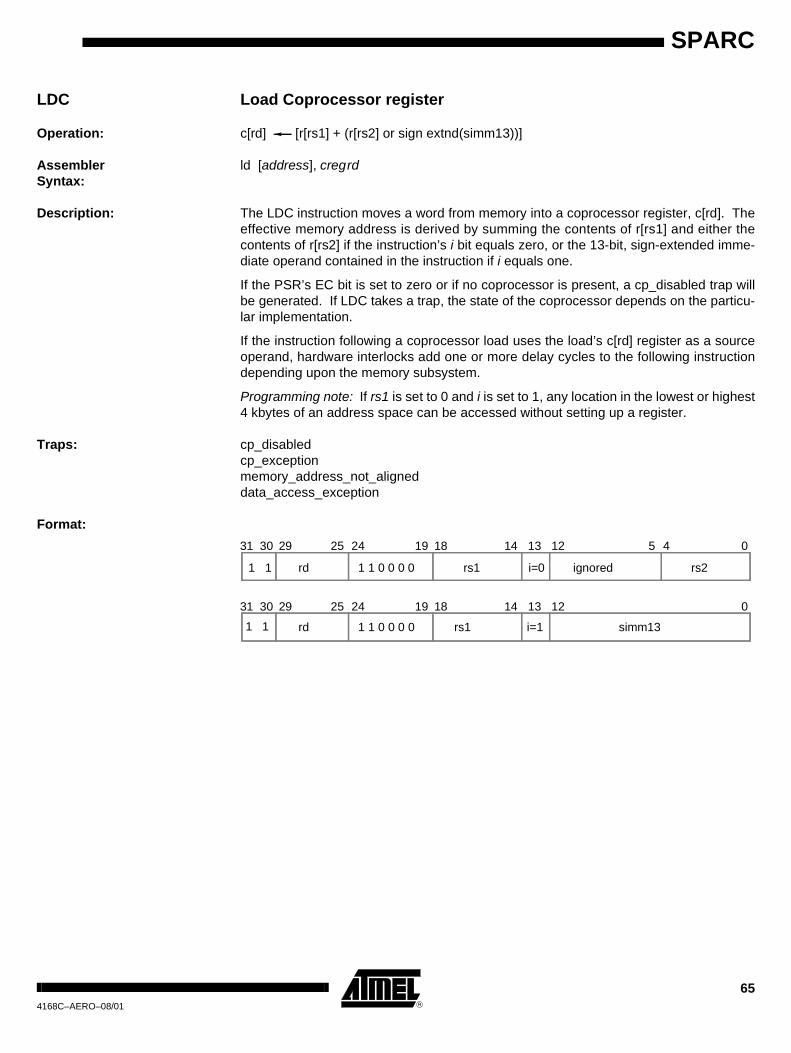
LDC Load Coprocessor register
Operation: c[rd] [r[rs1] + (r[rs2] or sign extnd(simm13))]
Assembler Syntax:
ld [address], cregrd
Description: The LDC instruction moves a word from memory into a coprocessor register, c[rd]. Theeffective memory address is derived by summing the contents of r[rs1] and either thecontents of r[rs2] if the instruction’s i bit equals zero, or the 13-bit, sign-extended imme-diate operand contained in the instruction if i equals one.
If the PSR’s EC bit is set to zero or if no coprocessor is present, a cp_disabled trap willbe generated. If LDC takes a trap, the state of the coprocessor depends on the particu-lar implementation.
If the instruction following a coprocessor load uses the load’s c[rd] register as a sourceoperand, hardware interlocks add one or more delay cycles to the following instructiondepending upon the memory subsystem.
Programming note: If rs1 is set to 0 and i is set to 1, any location in the lowest or highest4 kbytes of an address space can be accessed without setting up a register.
Traps: cp_disabledcp_exceptionmemory_address_not_aligneddata_access_exception
Format:
31 30 29 25 24 19 18 14 13 12 5 4 0
1 1 rd 1 1 0 0 0 0 rs1 rs2ignoredi=0
31 30 29 25 24 19 18 14 13 12 0
rd rs1 simm13i=11 1 1 1 0 0 0 0

66
SPARC4168C–AERO–08/01
LDCSR Load Coprocessor State Register
Operation: CSR [r[rs1] + (r[rs2] or sign extnd(simm13))]
Assembler Syntax:
ld [address], %csr
Description: The LDCSR instruction moves a word from memory into the Coprocessor State Regis-ter. The effective memory address is derived by summing the contents of r[rs1] andeither the contents of r[rs2] if the instruction’s i bit equals zero, or the 13-bit, sign-extended immediate operand contained in the instruction if i equals one.
If the PSR’s EC bit is set to zero or if no coprocessor is present, a cp_disabled trap willbe generated. If LDCSR takes a trap, the state of the coprocessor depends on the par-ticular implementation.
If the instruction following a LDCSR uses the CSR as a source operand, hardware inter-locks add one or more delay cycles to the following instruction depending uponimplementation of the coprocessor.
Programming note: If rs1 is set to 0 and i is set to 1, any location in the lowest or highest4 kbytes of an address space can be accessed without setting up a register.
Traps: cp_disabledcp_exceptionmemory_address_not_aligneddata_access_exception
Format:
31 30 29 25 24 19 18 14 13 12 5 4 0
1 1 rd 1 1 0 0 0 1 rs1 rs2ignoredi=0
31 30 29 25 24 19 18 14 13 12 0
rd rs1 simm13i=11 1 1 1 0 0 0 1

67
SPARC
4168C–AERO–08/01
LDD Load Doubleword
Operation: r[rd] [r[rs1] + (r[rs2] or sign extnd(simm13))]r[rd + 1] [(r[rs1] + (r[rs2] or sign extnd(simm13))) + 4]
Assembler Syntax:
ldd [address], regrd
Description: The LDD instruction moves a doubleword from memory into a destination register pair,r[rd] and r[rd+1]. The effective memory address is derived by summing the contents ofr[rs1] and either the contents of r[rs2] if the instruction’s i bit equals zero, or the 13-bit,sign-extended immediate operand contained in the instruction if i equals one. The mostsignificant memory word is always moved into the even-numbered destination registerand the least significant memory word is always moved into the next odd-numberedregister.
If a data_access_exception trap takes place during the effective address memoryaccess, the destination registers remain unchanged.
If the instruction following an integer load uses the load’s r[rd] register as a source oper-and, hardware interlocks add one or more delay cycles to the following instructiondepending upon the memory subsystem. For an LDD, this applies to both destinationregisters.
Programming note: If rs1 is set to 0 and i is set to 1, any location in the lowest or highest4 kbytes of an address space can be accessed without setting up a register.
Traps: memory_address_not_aligneddata_access_exception
Format:
31 30 29 25 24 19 18 14 13 12 5 4 0
1 1 rd 0 0 0 0 1 1 rs1 rs2ignoredi=0
31 30 29 25 24 19 18 14 13 12 0
rd rs1 simm13i=11 1 0 0 0 0 1 1

68
SPARC4168C–AERO–08/01
LDDA Load Doubleword from Alternate space(Privileged Instruction)
Operation: address space asir[rd] [r[rs1] + r[rs2]]r[rd +1] [r[rs1] + r[rs2] + 4]
Assembler Syntax:
ldda [regaddr] asi, regrd
Description: The LDDA instruction moves a doubleword from memory into the destination registers,r[rd] and r[rd+1]. The effective memory address is a combination of the address spacevalue given in the asi field and the address derived by summing the contents of r[rs1]and r[rs2]. The most significant memory word is always moved into the even-numbereddestination register and the least significant memory word is always moved into the nextodd-numbered register.
If a trap takes place during the effective address memory access, the destination regis-ters remain unchanged.
If the instruction following an integer load uses the load’s r[rd] register as a source oper-and, hardware interlocks add one or more delay cycles to the following instructiondepending upon the memory subsystem. For an LDDA, this applies to both destinationregisters.
Traps: illegal_instruction (if i=1)privileged_instruction (if S=0)memory_address_not_aligneddata_access_exception
Format:
31 30 29 25 24 19 18 14 13 12 5 4 0
1 1 rd 0 1 0 0 1 1 rs1 rs2asii=0

69
SPARC
4168C–AERO–08/01
LDDC Load Doubleword Coprocessor
Operation: c[rd ] [r[rs1] + (r[rs2] or sign extnd(simm13))]c[rd + 1] [(r[rs1] + (r[rs2] or sign extnd(simm13))) + 4]
Assembler Syntax:
ldd [address], cregrd
Description: The LDDC instruction moves a doubleword from memory into the coprocessor registers,c[rd] and c[rd+1]. The effective memory address is derived by summing the contents ofr[rs1] and either the contents of r[rs2] if the instruction’s i bit equals zero, or the 13-bit,sign-extended immediate operand contained in the instruction if i equals one. The mostsignificant memory word is always moved into the even-numbered destination registerand the least significant memory word is always moved into the next odd-numberedregister.
If the PSR’s EC bit is set to zero or if no coprocessor is present, a cp_disabled trap willbe generated. If LDDC takes a trap, the state of the coprocessor depends on the partic-ular implementation.
If the instruction following a coprocessor load uses the load’s c[rd] register as a sourceoperand, hardware interlocks add one or more delay cycles to the following instructiondepending upon the memory subsystem and coprocessor implementation. For anLDDC, this applies to both destination registers.
Programming note: If rs1 is set to 0 and i is set to 1, any location in the lowest or highest4 kbytes of an address space can be accessed without setting up a register.
Traps: cp_disabledcp_exceptionmemory_address_not_aligneddata_access_exception
Format:
31 30 29 25 24 19 18 14 13 12 5 4 0
1 1 rd 1 1 0 0 1 1 rs1 rs2ignoredi=0
31 30 29 25 24 19 18 14 13 12 0
rd rs1 simm13i=11 1 1 1 0 0 1 1

70
SPARC4168C–AERO–08/01
LDDF Load Doubleword Floating-Point
Operation: f[rd] [r[rs1] + (r[rs2] or sign extnd(simm13))]f[rd + 1] [(r[rs1] + (r[rs2] or sign extnd(simm13))) + 4]
Assembler Syntax:
ldd [address], fregrd
Description: The LDDF instruction moves a doubleword from memory into the floating-point regis-ters, f[rd] and f[rd+1]. The effective memory address is derived by summing thecontents of r[rs1] and either the contents of r[rs2] if the instruction’s i bit equals zero, orthe 13-bit, sign-extended immediate operand contained in the instruction if i equals one.The most significant memory word is always moved into the even-numbered destinationregister and the least significant memory word is always moved into the next odd-num-bered register.
If the PSR’s EF bit is set to zero or if no floating-point unit is present, an fp_disabled trapwill be generated. If a trap takes place during the effective address memory access, thedestination registers remain unchanged.
If the instruction following a floating-point load uses the load’s f[rd] register as a sourceoperand, hardware interlocks add one or more delay cycles to the following instructiondepending upon the memory subsystem. For an LDDF, this applies to both destinationregisters.
Programming note: If rs1 is set to 0 and i is set to 1, any location in the lowest or highest4 kbytes of an address space can be accessed without setting up a register.
Traps: fp_disabledfp_exception*memory_address_not_aligneddata_access_exception
Format:
Note: * An attempt to execute any FP instruction will cause a pending FP exception to be rec-ognized by the integer unit
31 30 29 25 24 19 18 14 13 12 5 4 0
1 1 rd 1 0 0 0 1 1 rs1 rs2ignoredi=0
31 30 29 25 24 19 18 14 13 12 0
rd rs1 simm13i=11 1 1 0 0 0 1 1
71
SPARC
4168C–AERO–08/01
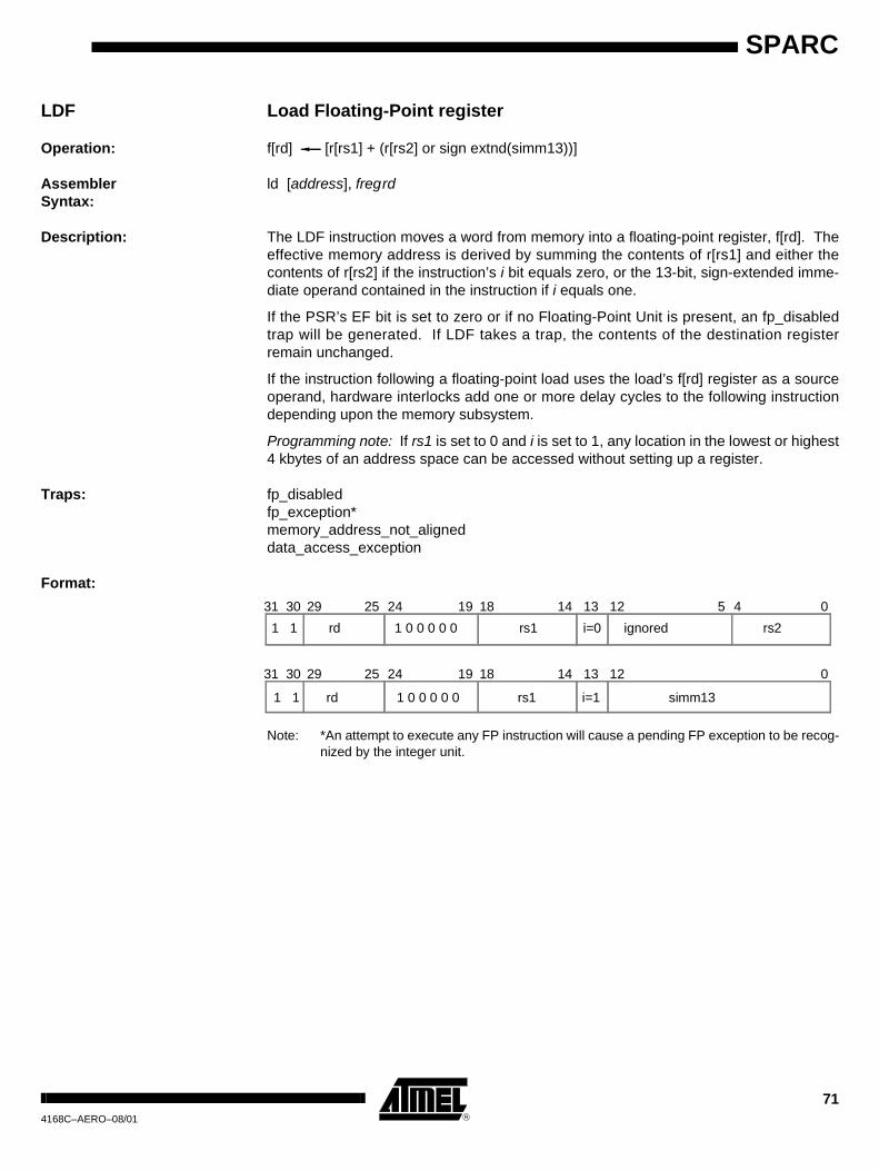
LDF Load Floating-Point register
Operation: f[rd] [r[rs1] + (r[rs2] or sign extnd(simm13))]
Assembler Syntax:
ld [address], fregrd
Description: The LDF instruction moves a word from memory into a floating-point register, f[rd]. Theeffective memory address is derived by summing the contents of r[rs1] and either thecontents of r[rs2] if the instruction’s i bit equals zero, or the 13-bit, sign-extended imme-diate operand contained in the instruction if i equals one.
If the PSR’s EF bit is set to zero or if no Floating-Point Unit is present, an fp_disabledtrap will be generated. If LDF takes a trap, the contents of the destination registerremain unchanged.
If the instruction following a floating-point load uses the load’s f[rd] register as a sourceoperand, hardware interlocks add one or more delay cycles to the following instructiondepending upon the memory subsystem.
Programming note: If rs1 is set to 0 and i is set to 1, any location in the lowest or highest4 kbytes of an address space can be accessed without setting up a register.
Traps: fp_disabledfp_exception*memory_address_not_aligneddata_access_exception
Format:
Note: *An attempt to execute any FP instruction will cause a pending FP exception to be recog-nized by the integer unit.
31 30 29 25 24 19 18 14 13 12 5 4 0
1 1 rd 1 0 0 0 0 0 rs1 rs2ignoredi=0
31 30 29 25 24 19 18 14 13 12 0
rd rs1 simm13i=11 1 1 0 0 0 0 0

72
SPARC4168C–AERO–08/01
LDFSR Load Floating-Point State Register
Operation: FSR [r[rs1] + (r[rs2] or sign extnd(simm13))]
Assembler Syntax:
“ld [address], %fsr
Description: The LDFSR instruction moves a word from memory into the floating-point state register.The effective memory address is derived by summing the contents of r[rs1] and eitherthe contents of r[rs2] if the instruction’s i bit equals zero, or the 13-bit, sign-extendedimmediate operand contained in the instruction if i equals one. This instruction will waitfor all pending FPops to complete execution before it loads the memory word into theFSR.
If the PSR’s EF bit is set to zero or if no floating-point unit is present, an fp_disabled trapwill be generated. If LDFSR takes a trap, the contents of the FSR remain unchanged.
If the instruction following a LDFSR uses the FSR as a source operand, hardware inter-locks add one or more cycle delay to the following instruction depending upon thememory subsystem.
Programming note: If rs1 is set to 0 and i is set to 1, any location in the lowest or highest4 kbytes of an address space can be accessed without setting up a register.
Traps: fp_disabledfp_exception*memory_address_not_aligneddata_access_exception
Format:
* NOTE: An attempt to execute any FP instruction will cause a pending FP exception to be recognized by the integer unit.
31 30 29 25 24 19 18 14 13 12 5 4 01 1 rd 1 0 0 0 0 1 rs1 rs2ignoredi=0
31 30 29 25 24 19 18 14 13 12 0
rd rs1 simm13i=11 1 1 0 0 0 0 1

73
SPARC
4168C–AERO–08/01
LDSB Load Signed Byte
Operation: r[rd] sign extnd[r[rs1] + (r[rs2] or sign extnd(simm13))]
Assembler Syntax:
ldsb [address], regrd
Description: The LDSB instruction moves a signed byte from memory into the destination register,r[rd]. The effective memory address is derived by summing the contents of r[rs1] andeither the contents of r[rs2] if the instruction’s i bit equals zero, or the 13-bit, sign-extended immediate operand contained in the instruction if i equals one. The fetchedbyte is right-justified and sign-extended in r[rd].
If LDSB takes a trap, the contents of the destination register remain unchanged.
If the instruction following an integer load uses the load’s r[rd] register as a source oper-and, hardware interlocks add one or more delay cycles to the following instructiondepending upon the memory subsystem.
Programming note: If rs1 is set to 0 and i is set to 1, any location in the lowest or highest4 kbytes of an address space can be accessed without setting up a register.
Traps: data_access_exception
Format:31 30 29 25 24 19 18 14 13 12 5 4 0
1 1 rd 0 0 1 0 0 1 rs1 rs2ignoredi=0
31 30 29 25 24 19 18 14 13 12 0
rd rs1 simm13i=11 1 0 0 1 0 0 1

74
SPARC4168C–AERO–08/01
LDSBA Load Signed Byte from Alternate space(Privileged Instruction)
Operation: address space asir[rd] sign extnd[r[rs1] + r[rs2]]
Assembler Syntax:
ldsba [regaddr] asi, regrd
Description: The LDSBA instruction moves a signed byte from memory into the destination register,r[rd]. The effective memory address is a combination of the address space value givenin the asi field and the address derived by summing the contents of r[rs1] and r[rs2].The fetched byte is right-justified and sign-extended in r[rd].
If LDSBA takes a trap, the contents of the destination register remain unchanged.
If the instruction following an integer load uses the load’s r[rd] register as a source oper-and, hardware interlocks add one or more delay cycles depending upon the memorysubsystem.
Traps: illegal_instruction (if i=1)privileged_instruction (if S=0)data_access_exception
Format:
31 30 29 25 24 19 18 14 13 12 5 4 01 1 rd 0 1 1 0 0 1 rs1 rs2asii=0

75
SPARC
4168C–AERO–08/01
LDSH Load Signed Halfword
Operation: r[rd] sign extnd[r[rs1] + (r[rs2] or sign extnd(simm13))]
Assembler Syntax:
ldsh [address], regrd
Description: The LDSH instruction moves a signed halfword from memory into the destination regis-ter, r[rd]. The effective memory address is derived by summing the contents of r[rs1]and either the contents of r[rs2] if the instruction’s i bit equals zero, or the 13-bit, sign-extended immediate operand contained in the instruction if i equals one. The fetchedhalfword is right-justified and sign-extended in r[rd].
If LDSH takes a trap, the contents of the destination register remain unchanged.
If the instruction following an integer load uses the load’s r[rd] register as a source oper-and, hardware interlocks add one or more delay cycles depending upon the memorysubsystem.
Programming note: If rs1 is set to 0 and i is set to 1, any location in the lowest or highest4 kbytes of an address space can be accessed without setting up a register.
Traps: memory_address_not_aligneddata_access_exception
Format:31 30 29 25 24 19 18 14 13 12 5 4 0
1 1 rd 0 0 1 0 1 0 rs1 rs2ignoredi=0
31 30 29 25 24 19 18 14 13 12 0
rd rs1 simm13i=11 1 0 0 1 0 1 0

76
SPARC4168C–AERO–08/01
LDSHA Load Signed Halfword from Alternate space(Privileged Instruction)
Operation: address space asir[rd] sign extnd[r[rs1] + r[rs2]]
Assembler Syntax:
ldsha [regaddr] asi, regrd
Description: The LDSHA instruction moves a signed halfword from memory into the destination reg-ister, r[rd]. The effective memory address is a combination of the address space valuegiven in the asi field and the address derived by summing the contents of r[rs1] andr[rs2]. The fetched halfword is right-justified and sign-extended in r[rd].
If LDSHA takes a trap, the contents of the destination register remain unchanged.
If the instruction following an integer load uses the load’s r[rd] register as a source oper-and, hardware interlocks add one or more delay cycles depending upon the memorysubsystem.
Traps: illegal_instruction (if i=1)privileged_instruction (if S=0)memory_address_not_aligneddata_access_exception
Format:
31 30 29 25 24 19 18 14 13 12 5 4 0
1 1 rd 0 1 1 0 1 0 rs1 rs2asii=0

77
SPARC
4168C–AERO–08/01
LDSTUB Atomic Load/Store Unsigned Byte
Operation: r[rd] zero extnd[r[rs1] + (r[rs2] or sign extnd(simm13))][r[rs1] + (r[rs2] or sign extnd(simm13))] FFFFFFFF H
Assembler Syntax:
ldstub [address], regrd
Description: The LDSTUB instruction moves an unsigned byte from memory into the destination reg-ister, r[rd], and rewrites the same byte in memory to all ones, while preventingasynchronous trap interruptions. In a multiprocessor system, two or more processorsexecuting atomic load/store instructions which address the same byte simultaneouslyare guaranteed to execute them serially, in some order.
The effective memory address is derived by summing the contents of r[rs1] and eitherthe contents of r[rs2] if the instruction’s i bit equals zero, or the 13-bit, sign-extendedimmediate operand contained in the instruction if i equals one. The fetched byte is right-justified and zero-extended in r[rd].
If the instruction following an integer load uses the load’s r[rd] register as a source oper-and, hardware interlocks add one or more delay cycles depending upon the memorysubsystem.
If LDSTUB takes a trap, the contents of the memory address remain unchanged.
Programming note: If rs1 is set to 0 and i is set to 1, any location in the lowest or highest4 kbytes of an address space can be accessed without setting up a register.
Traps: data_access_exception
Format:
31 30 29 25 24 19 18 14 13 12 5 4 0
1 1 rd 0 0 1 1 0 1 rs1 rs2ignoredi=0
31 30 29 25 24 19 18 14 13 12 0
rd rs1 simm13i=11 1 0 0 1 1 0 1

78
SPARC4168C–AERO–08/01
LDSTUBA Atomic Load/Store Unsigned Bytein Alternate space(Privileged Instruction)
Operation: address space asir[rd] zero extnd[r[rs1] + r[rs2]][r[rs1] + r[rs2]] FFFFFFFF H
Assembler Syntax:
ldstuba [regaddr] asi, regrd
Description: The LDSTUBA instruction moves an unsigned byte from memory into the destinationregister, r[rd], and rewrites the same byte in memory to all ones, while preventing asyn-chronous trap interruptions. In a multiprocessor system, two or more processorsexecuting atomic load/store instructions which address the same byte simultaneouslyare guaranteed to execute them in some serial order.
The effective memory address is a combination of the address space value given in theasi field and the address derived by summing the contents of r[rs1] and r[rs2]. Thefetched byte is right-justified and zero-extended in r[rd].
If the instruction following an integer load uses the load’s r[rd] register as a source oper-and, hardware interlocks add one or more delay cycles depending upon the memorysubsystem.
If LDSTUBA takes a trap, the contents of the memory address remain unchanged.
Traps: illegal_instruction (if i=1)privileged_instruction (if S=0)data_access_exception
Format:
31 30 29 25 24 19 18 14 13 12 5 4 0
1 1 rd rs1 rs2asii=00 1 1 1 0 1

79
SPARC
4168C–AERO–08/01
LDUB Load Unsigned Byte
Operation: r[rd] zero extnd[r[rs1] + (r[rs2] or sign extnd(simm13))]
Assembler Syntax:
ldub [address], regrd
Description: The LDUB instruction moves an unsigned byte from memory into the destination regis-ter, r[rd]. The effective memory address is derived by summing the contents of r[rs1]and either the contents of r[rs2] if the instruction’s i bit equals zero, or the 13-bit, sign-extended immediate operand contained in the instruction if i equals one. The fetchedbyte is right-justified and zero-extended in r[rd].
If LDUB takes a trap, the contents of the destination register remain unchanged.
If the instruction following an integer load uses the load’s r[rd] register as a source oper-and, hardware interlocks add one or more delay cycles depending upon the memorysubsystem.
Programming note: If rs1 is set to 0 and i is set to 1, any location in the lowest or highest4 kbytes of an address space can be accessed without setting up a register.
Traps: data_access_exception
Format:
31 30 29 25 24 19 18 14 13 12 5 4 0
1 1 rd 0 0 0 0 0 1 rs1 rs2ignoredi=0
31 30 29 25 24 19 18 14 13 12 0
rd rs1 simm13i=11 1 0 0 0 0 0 1

80
SPARC4168C–AERO–08/01
LDUBA Load Unsigned Byte from Alternate space(Privileged Instruction)
Operation: address space asir[rd] zero extnd[r[rs1] + r[rs2]]
Assembler Syntax:
lduba [regaddr] asi, regrd
Description: The LDUBA instruction moves an unsigned byte from memory into the destination regis-ter, r[rd]. The effective memory address is a combination of the address space valuegiven in the asi field and the address derived by summing the contents of r[rs1] andr[rs2]. The fetched byte is right-justified and zero-extended in r[rd].
If LDUBA takes a trap, the contents of the destination register remain unchanged.
If the instruction following an integer load uses the load’s r[rd] register as a source oper-and, hardware interlocks add one or more delay cycles depending upon the memorysubsystem.
Traps: illegal_instruction (if i=1)privileged_instruction (if S=0)data_access_exception
Format:
31 30 29 25 24 19 18 14 13 12 5 4 0
1 1 rd 0 1 0 0 0 1 rs1 rs2asii=0

81
SPARC
4168C–AERO–08/01
LDUH Load Unsigned Halfword
Operation: r[rd] zero extnd[r[rs1] + (r[rs2] or sign extnd(simm13))]
Assembler Syntax:
lduh [address], regrd
Description: The LDUH instruction moves an unsigned halfword from memory into the destinationregister, r[rd]. The effective memory address is derived by summing the contents ofr[rs1] and either the contents of r[rs2] if the instruction’s i bit equals zero, or the 13-bit,sign-extended immediate operand contained in the instruction if i equals one. Thefetched halfword is right-justified and zero-extended in r[rd].
If LDUH takes a trap, the contents of the destination register remain unchanged.
If the instruction following an integer load uses the load’s r[rd] register as a source oper-and, hardware interlocks add one or more delay cycles depending upon the memorysubsystem.
Programming note: If rs1 is set to 0 and i is set to 1, any location in the lowest or highest4 kbytes of an address space can be accessed without setting up a register.
Traps: memory_address_not_aligneddata_access_exception
Format:
31 30 29 25 24 19 18 14 13 12 5 4 0
1 1 rd 0 0 0 0 1 0 rs1 rs2ignoredi=0
31 30 29 25 24 19 18 14 13 12 0
rd rs1 simm13i=11 1 0 0 0 0 1 0

82
SPARC4168C–AERO–08/01
LDUHA Load Unsigned Halfword from Alternate space(Privileged Instruction)
Operation: address space asir[rd] zero extnd[r[rs1] + r[rs2]]
Assembler Syntax:
lduha [regaddr] asi, regrd
Description: The LDUHA instruction moves an unsigned halfword from memory into the destinationregister, r[rd]. The effective memory address is a combination of the address spacevalue given in the asi field and the address derived by summing the contents of r[rs1]and r[rs2]. The fetched halfword is right-justified and zero-extended in r[rd].
If LDUHA takes a trap, the contents of the destination register remain unchanged.
If the instruction following an integer load uses the load’s r[rd] register as a source oper-and, hardware interlocks add one or more delay cycles depending upon the memorysubsystem.
Traps: illegal_instruction (if i=1)privileged_instruction (if S=0)memory_address_not_aligneddata_access_exception
Format:
31 30 29 25 24 19 18 14 13 12 5 4 0
1 1 rd 0 1 0 0 1 0 rs1 rs2asii=0

83
SPARC
4168C–AERO–08/01
MULScc Multiply Step and modify icc
Operation: op1 = (n XOR v) CONCAT r[rs1]<31:1>if (Y<0> = 0) op2 = 0, else op2 = r[rs2] or sign extnd(simm13)r[rd] op1 + op2Y r[rs1]<0> CONCAT Y<31:1>n r[rd]<31>z if [r[rd]]=0 then 1, else 0v ((op1<31> AND op2<31> AND not r[rd]<31>)
OR (not op1<31> AND not op2<31> AND r[rd]<31>))c ((op1<31> AND op2<31>)
OR (not r[rd] AND (op1<31> OR op2<31>))
Assembler Syntax:
mulscc regrs1, reg_or_imm, regrd
Description: The multiply step instruction can be used to generate the 64-bit product of two signed orunsigned words. MULScc works as follows:
1. The “incoming partial product” in r[rs1] is shifted right by one bit and the high-order bit is replaced by the sign of the previous partial product (n XOR v). This is operand1.
2. If the least significant bit of the multiplier in the Y register equals zero, then operand2 is set to zero. If the LSB of the Y register equal one, then operand2 becomes the multiplicand, which is either the contents of r[rs2] if the instruction i field is zero, or sign extnd(simm13) if the i field is one. Operand2 is then added to operand1 and stored in r[rd] (the outgoing partial product).
3. The multiplier in the Y register is then shifted right by one bit and its high-order bit is replaced by the least significant bit of the incoming partial product in r[rs1].
4. The PSR’s integer condition codes are updated according to the addition per-formed in step 2.
Traps: none
Format:31 30 29 25 24 19 18 14 13 12 5 4 0
1 0 rd 1 0 0 1 0 0 rs1 rs2ignoredi=0
31 30 29 25 24 19 18 14 13 12 0
rd rs1 simm13i=11 0 1 0 0 1 0 0

84
SPARC4168C–AERO–08/01
OR Inclusive-Or
Operation: r[rd] r[rs1] OR (r[rs2] or sign extnd(simm13))
Assembler Syntax:
or regrs1, reg_or_imm, regrd
Description: This instruction does a bitwise logical OR of the contents of register r[rs1] with either thecontents of r[rs2] (if bit field i=0) or the 13-bit, sign-extended immediate value containedin the instruction (if bit field i=1). The result is stored in register r[rd].
Traps: none
Format:
31 30 29 25 24 19 18 14 13 12 5 4 0
1 0 rd 0 0 0 0 1 0 rs1 rs2ignoredi=0
31 30 29 25 24 19 18 14 13 12 0
rd rs1 simm13i=11 0 0 0 0 0 1 0

85
SPARC
4168C–AERO–08/01
ORcc Inclusive-Or and modify icc
Operation: r[rd] r[rs1] OR (r[rs2] or sign extnd(simm13))n r[rd]<31>z if [r[rd]]=0 then 1, else 0v 0c 0
Assembler Syntax:
orcc regrs1, reg_or_imm, regrd
Description: This instruction does a bitwise logical OR of the contents of register r[rs1] with either thecontents of r[rs2] (if bit field i=0) or the 13-bit, sign-extended immediate value containedin the instruction (if bit field i=1). The result is stored in register r[rd]. ORcc also modi-fies all the integer condition codes in the manner described above.
Traps: none
Format:
31 30 29 25 24 19 18 14 13 12 5 4 0
1 0 rd 0 1 0 0 1 0 rs1 rs2ignoredi=0
31 30 29 25 24 19 18 14 13 12 0
rd rs1 simm13i=11 0 0 1 0 0 1 0

86
SPARC4168C–AERO–08/01
ORN Inclusive-Or Not
Operation: r[rd] r[rs1] OR not(operand2), where operand2 = (r[rs2] or sign extnd(simm13))
Assembler Syntax:
orn regrs1, reg_or_imm, regrd
Description: This instruction does a bitwise logical OR of the contents of register r[rs1] with the one’scomplement of either the contents of r[rs2] (if bit field i=0) or the 13-bit, sign-extendedimmediate value contained in the instruction (if bit field i=1). The result is stored in reg-ister r[rd].
Traps: none
Format:
31 30 29 25 24 19 18 14 13 12 5 4 0
1 0 rd 0 0 0 1 1 0 rs1 rs2ignoredi=0
31 30 29 25 24 19 18 14 13 12 0
rd rs1 simm13i=11 0 0 0 0 1 1 0

87
SPARC
4168C–AERO–08/01
ORNcc Inclusive-Or Not and modify icc
Operation: r[rd] r[rs1] OR not(operand2), where operand2 = (r[rs2] or sign extnd(simm13))n r[rd]<31>z if [r[rd]]=0 then 1, else 0v 0c 0
Assembler Syntax:
orncc regrs1, reg_or_imm, regrd
Description:
This instruction does a bitwise logical OR of the contents of register r[rs1] with the one’scomplement of either the contents of r[rs2] (if bit field i=0) or the 13-bit, sign-extendedimmediate value contained in the instruction (if bit field i=1). The result is stored in reg-ister r[rd]. ORNcc also modifies all the integer condition codes in the manner describedabove.
Traps: none
Format:
31 30 29 25 24 19 18 14 13 12 5 4 0
1 0 rd 0 1 0 1 1 0 rs1 rs2ignoredi=0
31 30 29 25 24 19 18 14 13 12 0
rd rs1 simm13i=11 0 0 1 0 1 1 0

88
SPARC4168C–AERO–08/01
RDPSR Read Processor State Register(Privileged Instruction)
Operation: r[rd] PSR
Assembler Syntax:
rd %psr, regrd
Description: RDPSR copies the contents of the PSR into the register specified by the rd field.
Traps: privileged-instruction (if S=0)
Format:
31 30 29 25 24 19 18 0
1 0 rd 1 0 1 0 0 1 ignored

89
SPARC
4168C–AERO–08/01
RDTBR Read Trap Base Register(Privileged Instruction)
Operation: r[rd] TBR
Assembler Syntax:
rd %tbr, regrd
Description: RDTBR copies the contents of the TBR into the register specified by the rd field.
Traps: privileged_instruction (if S=0)
Format:
31 30 29 25 24 19 18 0
1 0 rd 1 0 1 0 1 1 ignored

90
SPARC4168C–AERO–08/01
RDWIM Read Window Invalid Mask register(Privileged Instruction)
Operation: r[rd] WIM
Assembler Syntax:
rd %wim, regrd
Description: RDWIM copies the contents of the WIM register into the register specified by the rd field.
Traps: privileged_instruction (if S=0)
Format:
31 30 29 25 24 19 18 0
1 0 rd 1 0 1 0 1 0 ignored

91
SPARC
4168C–AERO–08/01
RDY Read Y register
Operation: r[rd] Y
Assembler Syntax:
rd %y, regrd
Description: RDY copies the contents of the Y register into the register specified by the rd field.
Traps: none
Format:
31 30 29 25 24 19 18 0
1 0 1 0 1 0 0 0 ignoredrd

92
SPARC4168C–AERO–08/01
RESTORE Restore caller’s window
Operation: ncwp CWP + 1result r[rs1] + (r[rs2] or sign extnd(simm13))CWP ncwpr[rd] resultRESTORE does not affect condition codes
Assembler Syntax:
restore regrs1, reg_or_imm, regrd
Description: RESTORE adds one to the Current Window Pointer (modulo the number of imple-mented windows) and compares this value against the Window Invalid Mask register. Ifthe new window number corresponds to an invalidated window (WIM AND 2ncwp = 1), awindow_underflow trap is generated. If the new window number is not invalid (i.e., itscorresponding WIM bit is reset), then the contents of r[rs1] is added to either the con-tents of r[rs2] (field bit i = 1) or to the 13-bit, sign-extended immediate value contained inthe instruction (field bit i = 0). Because the CWP has not been updated yet, r[rs1] andr[rs2] are read from the currently addressed window (the called window).
The new CWP value is written into the PSR, causing the previous window (the caller’swindow) to become the active window. The result of the addition is now written into ther[rd] register of the restored window.
Note that arithmetic operations involving the CWP are always done modulo the numberof implemented windows (8 for the ERC 32).
Traps: window_underflow
Format:31 30 29 25 24 19 18 14 13 12 5 4 0
1 0 rd 1 1 1 1 0 1 rs1 rs2ignoredi=0
31 30 29 25 24 19 18 14 13 12 0
rd rs1 simm13i=11 0 1 1 1 1 0 1

93
SPARC
4168C–AERO–08/01
RETT Return from Trap(Privileged Instruction)
Operation: ncwp CWP + 1ET 1PC nPCnPC r[rs1] + (r[rs2] or sign extnd(simm13))CWP ncwpS pS
Assembler Syntax:
rett address
Description: RETT adds one to the Current Window Pointer (modulo the number of implementedwindows) and compares this value against the Window Invalid Mask register. If the newwindow number corresponds to an invalidated window (WIM AND 2ncwp = 1), awindow_underflow trap is generated. If the new window number is not invalid (i.e., itscorresponding WIM bit is reset), then RETT causes a delayed control transfer to theaddress derived by adding the contents of r[rs1] to either the contents of r[rs2] (field bit i= 1) or to the 13-bit, sign-extended immediate value contained in the instruction (field biti = 0).
Before the control transfer takes place, the new CWP value is written into the PSR,causing the previous window (the one in which the trap was taken) to become the activewindow. In addition, the PSR’s ET bit is set to one (traps enabled) and the previousSupervisor bit (pS) is restored to the S field.
Although in theory RETT is a delayed control transfer instruction, in practice, RETT mustalways be immediately preceded by a JMPL instruction, creating a delayed controltransfer couple. This has the effect of annulling the delay instruction.
If traps were already enabled before encountering the RETT instruction, anillegal_instruction trap is generated. If traps are not enabled (ET=0) when the RETT isencountered, but (1) the processor is not in supervisor mode (S=0), or (2) the windowunderflow condition described above occurs, or (3) if either of the two low-order bits ofthe target address are nonzero, then a reset trap occurs. If a reset trap does occur, thett field of the TBR encodes the trap condition: privileged_instruction, window_underflow,or memory_address_not_aligned.
Programming note: To re-execute the trapping instruction when returning from a traphandler, use the following sequence:
jmpl %17, %0 ! old PC
rett %18 ! old nPC
Note: The ERC 32 saves the PC in r[17] (local 1) and the nPC in r[18] (local2) of the trap win-dow upon entering a trap.
To return to the instruction after the trapping instruction (e.g., when the trapping instruc-tion is emulated), use the sequence:
jmpl %18, %0 ! old nPC
rett %18 + 4 ! old nPC + 4

94
SPARC4168C–AERO–08/01
RETT Return from Trap(Privileged Instruction)
Traps: illegal_instructionreset (privileged_instruction)reset (memory_address_not_aligned)reset (window_underflow)
Format:
31 30 29 25 24 19 18 14 13 12 5 4 0
1 0 ignored 1 1 1 0 0 1 rs1 rs2ignoredi=0
31 30 29 25 24 19 18 14 13 12 0
ignored rs1 simm13i=11 0 1 1 1 0 0 1

95
SPARC
4168C–AERO–08/01
SAVE Save caller’s window
Operation: ncwp CWP - 1result r[rs1] + (r[rs2] or sign extnd(simm13))CWP ncwpr[rd] resultSAVE does not affect condition codes
Assembler Syntax:
save regrs1, reg_or_imm, regrd
Description: SAVE subtracts one from the Current Window Pointer (modulo the number of imple-mented windows) and compares this value against the Window Invalid Mask register. Ifthe new window number corresponds to an invalidated window (WIM AND 2ncwp = 1), awindow_overflow trap is generated. If the new window number is not invalid (i.e., its cor-responding WIM bit is reset), then the contents of r[rs1] is added to either the contents ofr[rs2] (field bit i = 1) or to the 13-bit, sign-extended immediate value contained in theinstruction (field bit i = 0). Because the CWP has not been updated yet, r[rs1] and r[rs2]are read from the currently addressed window (the calling window).
The new CWP value is written into the PSR, causing the active window to become theprevious window, and the called window to become the active window. The result of theaddition is now written into the r[rd] register of the new window.
Note that arithmetic operations involving the CWP are always done modulo the numberof implemented windows (8 for the ERC 32).
Traps: window_overflow
Format:
31 30 29 25 24 19 18 14 13 12 5 4 0
1 0 rd 1 1 1 1 0 0 rs1 rs2ignoredi=0
31 30 29 25 24 19 18 14 13 12 0
rd rs1 simm13i=11 0 1 1 1 1 0 0

96
SPARC4168C–AERO–08/01
SETHI Set High 22 bits of r register
Operation: r[rd]<31:10> imm22r[rd]<9:0> 0
Assembler Syntax:
sethi const22, regrd
sethi %hi value, regrd
Description: SETHI zeros the ten least significant bits of the contents of r[rd] and replaces its high-order 22 bits with imm22. The condition codes are not affected.
Programming note: SETHI 0, %0 is the preferred instruction to use as a NOP, becauseit will not increase execution time if it follows a load instruction.
Traps: none
Format:
31 30 29 25 24 21 0
0 0 rd 1 0 0 imm22
22

97
SPARC
4168C–AERO–08/01
SLL Shift Left Logical
Operation: r[rd] r[rs1] SLL by (r[rs2] or shcnt)
Assembler Syntax:
sll regrs1, reg_or_imm, regrd
Description: SLL shifts the contents of r[rs1] left by the number of bits specified by the shift count, fill-ing the vacated positions with zeros. The shifted results are written into r[rd]. No shiftoccurs if the shift count is zero.
If the i bit field equals zero, the shift count for SLL is the least significant five bits of thecontents of r[rs2]. If the i bit field equals one, the shift count for SLL is the 13-bit, signextended immediate value, simm13. In the instruction format and the operation descrip-tion above, the least significant five bits of simm13 is called shcnt.
This instruction does not modify the condition codes.
Traps: none
Format:
31 30 29 25 24 19 18 14 13 12 5 4 0
1 0 rd 1 0 0 1 0 1 rs1 rs2ignoredi=0
31 30 29 25 24 19 18 14 13 12 0
rd rs1 shcnti=11 0 1 0 0 1 0 1 ignored
5 4

98
SPARC4168C–AERO–08/01
SRA Shift Right Arithmetic
Operation: r[rd] r[rs1] SRA by (r[rs2] or shcnt)
Assembler Syntax:
sra regrs1, reg_or_imm, regrd
Description: SRA shifts the contents of r[rs1] right by the number of bits specified by the shift count,filling the vacated positions with the MSB of r[rs1]. The shifted results are written intor[rd]. No shift occurs if the shift count is zero.
If the i bit field equals zero, the shift count for SRA is the least significant five bits of thecontents of r[rs2]. If the i bit field equals one, the shift count for SRA is the 13-bit, signextended immediate value, simm13. In the instruction format and the operation descrip-tion above, the least significant five bits of simm13 is called shcnt.
This instruction does not modify the condition codes.
Programming note: A “Shift Left Arithmetic by 1 (and calculate overflow)” can be imple-mented with an ADDcc instruction.
Traps: none
Format:
31 30 29 25 24 19 18 14 13 12 5 4 0
1 0 rd 1 0 0 1 1 1 rs1 rs2ignoredi=0
31 30 29 25 24 19 18 14 13 12 0
rd rs1 shcnti=11 0 1 0 0 1 1 1 ignored
5 4

99
SPARC
4168C–AERO–08/01
SRL Shift Right Logical
Operation: r[rd] r[rs1] SRL by (r[rs2] or shcnt)
Assembler Syntax:
srl regrs1, reg_or_imm, regrd
Description: SRL shifts the contents of r[rs1] right by the number of bits specified by the shift count,filling the vacated positions with zeros. The shifted results are written into r[rd]. No shiftoccurs if the shift count is zero.
If the i bit field equals zero, the shift count for SRL is the least significant five bits of thecontents of r[rs2]. If the i bit field equals one, the shift count for SRL is the 13-bit, signextended immediate value, simm13. In the instruction format and the operation descrip-tion above, the least significant five bits of simm13 is called shcnt.
This instruction does not modify the condition codes.
Traps: none
Format:
31 30 29 25 24 19 18 14 13 12 5 4 0
1 0 rd 1 0 0 1 1 0 rs1 rs2ignoredi=0
31 30 29 25 24 19 18 14 13 12 0
rd rs1 shcnti=11 0 1 0 0 1 1 0
5 4
ignored

100
SPARC4168C–AERO–08/01
ST Store Word
Operation: [r[rs1] + (r[rs2] or sign extnd(simm13))] r[rd]
Assembler Syntax:
st regrd, [address]
Description: The ST instruction moves a word from the destination register, r[rd], into memory. Theeffective memory address is derived by summing the contents of r[rs1] and either thecontents of r[rs2] if the instruction’s i bit equals zero, or the 13-bit, sign-extended imme-diate operand contained in the instruction if i equals one.
If ST takes a trap, the contents of the memory address remain unchanged.
Programming note: If rs1 is set to 0 and i is set to 1, any location in the lowest or highest4 kbytes of an address space can be written to without setting up a register.
Traps:
memory_address_not_aligneddata_access_exception
Format:
31 30 29 25 24 19 18 14 13 12 5 4 0
1 1 rd 0 0 0 1 0 0 rs1 rs2ignoredi=0
31 30 29 25 24 19 18 14 13 12 0
rd rs1 simm13i=11 1 0 0 0 1 0 0

101
SPARC
4168C–AERO–08/01
STA Store Word into Alternate space(Privileged Instruction)
Operation: address space asi[r[rs1] + r[rs2]] r[rd]
Assembler Syntax:
sta regrd, [regaddr] asi
Description: The STA instruction moves a word from the destination register, r[rd], into memory. Theeffective memory address is a combination of the address space value given in the asifield and the address derived by summing the contents of r[rs1] and r[rs2].
If STA takes a trap, the contents of the memory address remain unchanged.
Traps: illegal_instruction (if i=1)privileged_instruction (if S=0)memory_address_not_aligneddata_access_exception
Format:
31 30 29 25 24 19 18 14 13 12 5 4 0
1 1 rd 0 1 0 1 0 0 rs1 rs2asii=0

102
SPARC4168C–AERO–08/01
STB Store Byte
Operation: [r[rs1] + (r[rs2] or sign extnd(simm13))] r[rd]
Assembler Syntax:
stb regrd, [address]
synonyms: stub, stsb
Description: The STB instruction moves the least significant byte from the destination register, r[rd],into memory. The effective memory address is derived by summing the contents ofr[rs1] and either the contents of r[rs2] if the instruction’s i bit equals zero, or the 13-bit,sign-extended immediate operand contained in the instruction if i equals one.
If STB takes a trap, the contents of the memory address remain unchanged.
Programming note: If rs1 is set to 0 and i is set to 1, any location in the lowest or highest4 kbytes of an address space can be written to without setting up a register.
Traps: data_access_exception
Format:31 30 29 25 24 19 18 14 13 12 5 4 0
1 1 rd 0 0 0 1 0 1 rs1 rs2ignoredi=0
31 30 29 25 24 19 18 14 13 12 0
rd rs1 simm13i=11 1 0 0 0 1 0 1

103
SPARC
4168C–AERO–08/01
STBA Store Byte into Alternate space(Privileged Instruction)
Operation: address space asi[r[rs1] + r[rs2]] r[rd]
Assembler Syntax:
stba regrd, [regaddr] asi
synonyms: stuba, stsba
Description: The STBA instruction moves the least significant byte from the destination register, r[rd],into memory. The effective memory address is a combination of the address spacevalue given in the asi field and the address derived by summing the contents of r[rs1]and r[rs2].
If STBA takes a trap, the contents of the memory address remain unchanged.
Traps: illegal_instruction (if i=1)privileged_instruction (if S=0)data_access_exception
Format:
31 30 29 25 24 19 18 14 13 12 5 4 0
1 1 rd 0 1 0 1 0 1 rs1 rs2asii=0

104
SPARC4168C–AERO–08/01
STC Store Coprocessor register
Operation: [r[rs1] + (r[rs2] or sign extnd(simm13))] c[rd]
Assembler Syntax:
st cregrd, [address]
Description: The STC instruction moves a word from a coprocessor register, c[rd], into memory. Theeffective memory address is derived by summing the contents of r[rs1] and either thecontents of r[rs2] if the instruction’s i bit equals zero, or the 13-bit, sign-extended imme-diate operand contained in the instruction if i equals one.
If the PSR’s EC bit is set to zero or if no coprocessor is present, a cp_disabled trap willbe generated. If STC takes a trap, memory remains unchanged.
Programming note: If rs1 is set to 0 and i is set to 1, any location in the lowest or highest4 kbytes of an address space can be written to without setting up a register.
Traps: cp_disabledcp_exceptionmemory_address_not_aligneddata_access_exception
Format:
31 30 29 25 24 19 18 14 13 12 5 4 0
1 1 rd 1 1 0 1 0 0 rs1 rs2ignoredi=0
31 30 29 25 24 19 18 14 13 12 0
rd rs1 simm13i=11 1 1 1 0 1 0 0

105
SPARC
4168C–AERO–08/01
STCSR Store Coprocessor State Register
Operation: [r[rs1] + (r[rs2] or sign extnd(simm13))] CSR
Assembler Syntax:
st %csr, [address]
Description: The STCSR instruction moves the contents of the Coprocessor State Register intomemory. The effective memory address is derived by summing the contents of r[rs1]and either the contents of r[rs2] if the instruction’s i bit equals zero, or the 13-bit, sign-extended immediate operand contained in the instruction if i equals one.
If the PSR’s EC bit is set to zero or if no coprocessor is present, a cp_disabled trap willbe generated. If STCSR takes a trap, the contents of the memory address remainunchanged.
Programming note: If rs1 is set to 0 and i is set to 1, any location in the lowest or highest4 kbytes of an address space can be written to without setting up a register.
Traps: cp_disabledcp_exceptionmemory_address_not_aligneddata_access_exception
Format:
31 30 29 25 24 19 18 14 13 12 5 4 0
1 1 rd 1 1 0 1 0 1 rs1 rs2ignoredi=0
31 30 29 25 24 19 18 14 13 12 0
rd rs1 simm13i=11 1 1 1 0 1 0 1

106
SPARC4168C–AERO–08/01
STD Store Doubleword
Operation: [r[rs1] + (r[rs2] or sign extnd(simm13))] r[rd][r[rs1] + (r[rs2] or sign extnd(simm13)) + 4] r[rd + 1]
Assembler Syntax:
std regrd, [address]
Description: The STD instruction moves a doubleword from the destination register pair, r[rd] andr[rd+1], into memory. The effective memory address is derived by summing the con-tents of r[rs1] and either the contents of r[rs2] if the instruction’s i bit equals zero, or the13-bit, sign-extended immediate operand contained in the instruction if i equals one.The most significant word in the even-numbered destination register is written into mem-ory at the effective address and the least significant memory word in the next odd-numbered register is written into memory at the effective address + 4.
If a data_access_exception trap takes place during the effective address memoryaccess, memory remains unchanged.
Programming note: If rs1 is set to 0 and i is set to 1, any location in the lowest or highest4 kbytes of an address space can be written to without setting up a register.
Traps: memory_address_not_aligneddata_access_exception
Format:
31 30 29 25 24 19 18 14 13 12 5 4 0
1 1 rd 0 0 0 1 1 1 rs1 rs2ignoredi=0
31 30 29 25 24 19 18 14 13 12 0
rd rs1 simm13i=11 1 0 0 0 1 1 1

107
SPARC
4168C–AERO–08/01
STDA Store Doubleword into Alternate space(Privileged Instruction)
Operation: address space asi[r[rs1] + (r[rs2] or sign extnd(simm13))] r[rd][r[rs1] + (r[rs2] or sign extnd(simm13)) + 4] r[rd + 1]
Assembler Syntax:
stda regrd, [regaddr] asi
Description: The STDA instruction moves a doubleword from the destination register pair, r[rd] andr[rd+1], into memory. The effective memory address is a combination of the addressspace value given in the asi field and the address derived by summing the contents ofr[rs1] and r[rs2]. The most significant word in the even-numbered destination register iswritten into memory at the effective address and the least significant memory word inthe next odd-numbered register is written into memory at the effective address + 4.
If a data_access_exception trap takes place during the effective address memoryaccess, memory remains unchanged.
Traps: illegal_instruction (if i=1)privileged_instruction (if S=0)memory_address_not_aligneddata_access_exception
Format:
31 30 29 25 24 19 18 14 13 12 5 4 0
1 1 rd 0 1 0 1 1 1 rs1 rs2asii=0

108
SPARC4168C–AERO–08/01
STDC Store Doubleword Coprocessor
Operation: [r[rs1] + (r[rs2] or sign extnd(simm13))] c[rd][r[rs1] + (r[rs2] or sign extnd(simm13)) + 4] c[rd + 1]
Assembler Syntax:
std cregrd, [address]
Description: The STDC instruction moves a doubleword from the coprocessor register pair, c[rd] andc[rd+1], into memory. The effective memory address is derived by summing the con-tents of r[rs1] and either the contents of r[rs2] if the instruction’s i bit equals zero, or the13-bit, sign-extended immediate operand contained in the instruction if i equals one.The most significant word in the even-numbered destination register is written into mem-ory at the effective address and the least significant memory word in the next odd-numbered register is written into memory at the effective address + 4.
If the PSR’s EC bit is set to zero or if no coprocessor is present, a cp_disabled trap willbe generated. If a data_access_exception trap takes place during the effective addressmemory access, memory remains unchanged.
Programming note: If rs1 is set to 0 and i is set to 1, any location in the lowest or highest4 kbytes of an address space can be written to without setting up a register.
Traps: cp_disabledcp_exceptionmemory_address_not_aligneddata_access_exception
Format:
31 30 29 25 24 19 18 14 13 12 5 4 0
1 1 rd 1 1 0 1 1 1 rs1 rs2ignoredi=0
31 30 29 25 24 19 18 14 13 12 0
rd rs1 simm13i=11 1 1 1 0 1 1 1

109
SPARC
4168C–AERO–08/01
STDCQ Store Doubleword Coprocessor Queue(Privileged Instruction)
Operation: [r[rs1] + (r[rs2] or sign extnd(simm13))] CQ.ADDR[r[rs1] + (r[rs2] or sign extnd(simm13)) + 4] CQ.INSTR
Assembler Syntax:
std %cq, [address]
Description: The STDCQ instruction moves the front entry of the Coprocessor Queue into memory.The effective memory address is derived by summing the contents of r[rs1] and eitherthe contents of r[rs2] if the instruction’s i bit equals zero, or the 13-bit, sign-extendedimmediate operand contained in the instruction if i equals one. The address portion ofthe queue entry is written into memory at the effective address and the instruction por-tion of the entry is written into memory at the effective address + 4.
If the PSR’s EC bit is set to zero or if no coprocessor is present, a cp_disabled trap willbe generated. If a data_access_exception trap takes place during the effective addressmemory access, memory remains unchanged.
Programming note: If rs1 is set to 0 and i is set to 1, any location in the lowest or highest4 kbytes of an address space can be written to without setting up a register.
Traps: cp_disabledcp_exceptionprivileged_instruction (if S=0)memory_address_not_aligneddata_access_exception
Format:
31 30 29 25 24 19 18 14 13 12 5 4 0
1 1 rd 1 1 0 1 1 0 rs1 rs2ignoredi=0
31 30 29 25 24 19 18 14 13 12 0
rd rs1 simm13i=11 1 1 1 0 1 1 0

110
SPARC4168C–AERO–08/01
STDF Store Doubleword Floating-Point
Operation: [r[rs1] + (r[rs2] or sign extnd(simm13))] f[rd][r[rs1] + (r[rs2] or sign extnd(simm13)) + 4] f[rd + 1]
Assembler Syntax:
std fregrd, [address]
Description: The STDF instruction moves a doubleword from the floating-point register pair, f[rd] andf[rd+1], into memory. The effective memory address is derived by summing the con-tents of r[rs1] and either the contents of r[rs2] if the instruction’s i bit equals zero, or the13-bit, sign-extended immediate operand contained in the instruction if i equals one.The most significant word in the even-numbered destination register is written into mem-ory at the effective address and the least significant memory word in the next odd-numbered register is written into memory at the effective address + 4.
If the PSR’s EF bit is set to zero or if no floating-point unit is present, an fp_disabled trapwill be generated. If a trap takes place, memory remains unchanged.
Programming note: If rs1 is set to 0 and i is set to 1, any location in the lowest or highest4 kbytes of an address space can be written to without setting up a register.
Traps: fp_disabledfp_exception*memory_address_not_aligneddata_access_exception
Format:
* NOTE: An attempt to execute any FP instruction will cause a pending FP exception to be recognized by the integer unit.
31 30 29 25 24 19 18 14 13 12 5 4 0
1 1 rd 1 0 0 1 1 1 rs1 rs2ignoredi=0
31 30 29 25 24 19 18 14 13 12 0
rd rs1 simm13i=11 1 1 0 0 1 1 1

111
SPARC
4168C–AERO–08/01
STDFQ Store Doubleword Floating-Point Queue(Privileged Instruction)
Operation: [r[rs1] + (r[rs2] or sign extnd(simm13))] FQ.ADDR[r[rs1] + (r[rs2] or sign extnd(simm13)) + 4] FQ.INSTR
Assembler Syntax:
std %fq, [address]
Description: The STDFQ instruction moves the front entry of the floating-point queue into memory.The effective memory address is derived by summing the contents of r[rs1] and eitherthe contents of r[rs2] if the instruction’s i bit equals zero, or the 13-bit, sign-extendedimmediate operand contained in the instruction if i equals one. The address portion ofthe queue entry is written into memory at the effective address and the instruction por-tion of the entry is written into memory at the effective address + 4. If the FPU is inexception mode, the queue is then advanced to the next entry, or it becomes empty (asindicated by the qne bit in the FSR).
If the PSR’s EF bit is set to zero or if no floating-point unit is present, an fp_disabled trapwill be generated. If a trap takes place, memory remains unchanged.
Programming note: If rs1 is set to 0 and i is set to 1, any location in the lowest or highest4 kbytes of an address space can be written to without setting up a register.
Traps: fp_disabledfp_exception*privileged_instruction (if S=0)memory_address_not_aligneddata_access_exception
Format:
* NOTE: An attempt to execute any FP instruction will cause a pending FP exception to be recognized by the integer unit.
31 30 29 25 24 19 18 14 13 12 5 4 0
1 1 rd 1 0 0 1 1 0 rs1 rs2ignoredi=0
31 30 29 25 24 19 18 14 13 12 0
rd rs1 simm13i=11 1 1 0 0 1 1 0

112
SPARC4168C–AERO–08/01
STF Store Floating-Point register
Operation: [r[rs1] + (r[rs2] or sign extnd(simm13))] f[rd]
Assembler Syntax:
st fregrd, [address]
Description: The STF instruction moves a word from a floating-point register, f[rd], into memory.The effective memory address is derived by summing the contents of r[rs1] and eitherthe contents of r[rs2] if the instruction’s i bit equals zero, or the 13-bit, sign-extendedimmediate operand contained in the instruction if i equals one.
If the PSR’s EF bit is set to zero or if no floating-point unit is present, an fp_disabled trapwill be generated. If STF takes a trap, memory remains unchanged.
Programming note: If rs1 is set to 0 and i is set to 1, any location in the lowest or highest4 kbytes of an address space can be written to without setting up a register.
Traps: fp_disabledfp_exception*memory_address_not_aligneddata_access_exception
Format:
* NOTE: An attempt to execute any FP instruction will cause a pending FP exception to be recognized by the integer unit.
31 30 29 25 24 19 18 14 13 12 5 4 0
1 1 rd 1 0 0 1 0 0 rs1 rs2ignoredi=0
31 30 29 25 24 19 18 14 13 12 0
rd rs1 simm13i=11 1 1 0 0 1 0 0

113
SPARC
4168C–AERO–08/01
STFSR Store Floating-Point State Register
Operation: [r[rs1] + (r[rs2] or sign extnd(simm13))] FSR
Assembler Syntax:
st %fsr, [address]
Description: The STFSR instruction moves the contents of the Floating-Point State Register intomemory. The effective memory address is derived by summing the contents of r[rs1]and either the contents of r[rs2] if the instruction’s i bit equals zero, or the 13-bit, sign-extended immediate operand contained in the instruction if i equals one. This instruc-tion will wait for all pending FPops to complete execution before it writes the FSR intomemory.
If the PSR’s EF bit is set to zero or if no floating-point unit is present, an fp_disabled trapwill be generated. If STFSR takes a trap, the contents of the memory address remainunchanged.
Programming note: If rs1 is set to 0 and i is set to 1, any location in the lowest or highest4 kbytes of an address space can be written to without setting up a register.
Traps: fp_disabledfp_exception*memory_address_not_aligneddata_access_exception
Format:
* NOTE: An attempt to execute any FP instruction will cause a pending FP exception to be recognized by the integer unit.
31 30 29 25 24 19 18 14 13 12 5 4 0
1 1 rd 1 0 0 1 0 1 rs1 rs2ignoredi=0
31 30 29 25 24 19 18 14 13 12 0
rd rs1 simm13i=11 1 1 0 0 1 0 1

114
SPARC4168C–AERO–08/01
STH Store Halfword
Operation: [r[rs1] + (r[rs2] or sign extnd(simm13))] r[rd]
Assembler Syntax:
sth regrd, [address] synonyms: stuh, stsh
Description: The STH instruction moves the least significant halfword from the destination register,r[rd], into memory. The effective memory address is derived by summing the contentsof r[rs1] and either the contents of r[rs2] if the instruction’s i bit equals zero, or the 13-bit,sign-extended immediate operand contained in the instruction if i equals one.
If STH takes a trap, the contents of the memory address remain unchanged.
Programming note: If rs1 is set to 0 and i is set to 1, any location in the lowest or highest4 kbytes of an address space can be written to without setting up a register.
Traps: memory_address_not_aligneddata_access_exception
Format:31 30 29 25 24 19 18 14 13 12 5 4 0
1 0 rd 0 0 0 1 1 0 rs1 rs2ignoredi=0
31 30 29 25 24 19 18 14 13 12 0
rd rs1 simm13i=11 0 0 0 0 1 1 0

115
SPARC
4168C–AERO–08/01
STHA Store Halfword into Alternate space(Privileged Instruction)
Operation: address space asi[r[rs1] + (r[rs2] or sign extnd(simm13))] r[rd]
Assembler Syntax:
stha regrd, [address]
synonyms: stuha, stsha
Description: The STHA instruction moves the least significant halfword from the destination register,r[rd], into memory. The effective memory address is a combination of the addressspace value given in the asi field and the address derived by summing the contents ofr[rs1] and r[rs2].
If STHA takes a trap, the contents of the memory address remain unchanged.
Traps: illegal_instruction (if i=1)privileged_instruction (if S=0)memory_address_not_aligneddata_access_exception
Format:
31 30 29 25 24 19 18 14 13 12 5 4 0
1 1 rd 0 1 0 1 1 0 rs1 rs2asii=0

116
SPARC4168C–AERO–08/01
SUB Subtract
Operation: r[rd] r[rs1] - (r[rs2] or sign extnd(simm13))
Assembler Syntax:
sub regrs1, reg_or_imm, regrd
Description: The SUB instruction subtracts either the contents of the register named in the rs2 field,r[rs2], if the instruction’s i bit equals zero, or the 13-bit, sign-extended immediate oper-and contained in the instruction if i equals one, from register r[rs1]. The result is placedin the register specified in the rd field.
Traps: none
Format:31 30 29 25 24 19 18 14 13 12 5 4 0
1 0 rd 0 0 0 1 0 0 rs1 rs2ignoredi=0
31 30 29 25 24 19 18 14 13 12 0
rd rs1 simm13i=11 0 0 0 0 1 0 0

117
SPARC
4168C–AERO–08/01
SUBcc Subtract and modify icc
Operation: r[rd] r[rs1] - operand2, where operand2 = (r[rs2] or sign extnd(simm13))n r[rd]<31>z if r[rd] =0 then 1, else 0v (r[rs1]<31> AND not operand2<31> AND not r[rd]<31>)
OR (not r[rs1]<31> AND operand2<31> AND r[rd]<31>)c (not r[rs1]<31> AND operand2<31>)
OR (r[rd]<31> AND (not r[rs1]<31> OR operand2<31>))
Assembler Syntax:
subcc regrs1, reg_or_imm, regrd
Description: The SUBcc instruction subtracts either the contents of register r[rs2] (if the instruction’si bit equals zero) or the 13-bit, sign-extended immediate operand contained in theinstruction (if i equals one) from register r[rs1]. The result is placed in register r[rd]. Inaddition, SUBcc modifies all the integer condition codes in the manner described above.
Programming note: A SUBcc instruction with rd = 0 can be used for signed andunsigned integer comparison.
Traps: none
Format:
31 30 29 25 24 19 18 14 13 12 5 4 0
1 0 rd 0 1 0 1 0 0 rs1 rs2ignoredi=0
31 30 29 25 24 19 18 14 13 12 0
rd rs1 simm13i=11 0 0 1 0 1 0 0

118
SPARC4168C–AERO–08/01
SUBX Subtract with Carry
Operation: r[rd] r[rs1] - (r[rs2] or sign extnd(simm13)) - c
Assembler Syntax:
subx regrs1, reg_or_imm, regrd
Description: SUBX subtracts either the contents of register r[rs2] (if the instruction’s i bit equals zero)or the 13-bit, sign-extended immediate operand contained in the instruction (if i equalsone) from register r[rs1]. It then subtracts the PSR’s carry bit (c) from that result. Thefinal result is placed in the register specified in the rd field.
Traps: none
Format:
31 30 29 25 24 19 18 14 13 12 5 4 0
1 0 rd 0 0 1 1 0 0 rs1 rs2ignoredi=0
31 30 29 25 24 19 18 14 13 12 0
rd rs1 simm13i=11 0 0 0 1 1 0 0

119
SPARC
4168C–AERO–08/01
SUBXcc Subtract with Carry and modify icc
Operation: r[rd] r[rs1] - operand2 - c, where operand2 = (r[rs2] or sign extnd(simm13))n r[rd]<31>z if r[rd] =0 then 1, else 0v (r[rs1]<31> AND not operand2<31> AND not r[rd]<31>)
OR (not r[rs1]<31> AND operand2<31> AND r[rd]<31>)c (not r[rs1]<31> AND operand2<31>)
OR (r[rd]<31> AND (not r[rs1]<31> OR operand2<31>))
Assembler Syntax:
subxcc regrs1, reg_or_imm, regrd
Description: SUBXcc subtracts either the contents of register r[rs2] (if the instruction’s i bit equalszero) or the 13-bit, sign-extended immediate operand contained in the instruction (if iequals one) from register r[rs1]. It then subtracts the PSR’s carry bit (c) from that result.The final result is placed in the register specified in the rd field. In addition, SUBXccmodifies all the integer condition codes in the manner described above.
Traps: none
Format:
31 30 29 25 24 19 18 14 13 12 5 4 0
1 0 rd 0 1 1 1 0 0 rs1 rs2ignoredi=0
31 30 29 25 24 19 18 14 13 12 0
rd rs1 simm13i=11 0 0 1 1 1 0 0

120
SPARC4168C–AERO–08/01
SWAP Swap r register with memory
Operation: word [r[rs1] + (r[rs2] or sign extnd(simm13))]temp r[rd]r[rd] wordr[rs1] + (r[rs2] or sign extnd(simm13)) temp
Assembler Syntax:
swap [source], regrd
Description: SWAP atomically exchanges the contents of r[rd] with the contents of a memory loca-tion, i.e., without allowing asynchronous trap interruptions. In a multiprocessor system,two or more processors executing SWAP instructions simultaneously are guaranteed toexecute them serially, in some order.
The effective memory address is derived by summing the contents of r[rs1] and eitherthe contents of r[rs2] if the instruction’s i bit equals zero, or the 13-bit, sign-extendedimmediate operand contained in the instruction if i equals one.
If SWAP takes a trap, the contents of the memory address and the destination registerremain unchanged.
Programming note: If rs1 is set to 0 and i is set to 1, any location in the lowest or highest4 kbytes of an address space can be accessed without setting up a register.
Traps: memory_address_not_aligneddata_access_exception
Format:
31 30 29 25 24 19 18 14 13 12 5 4 0
1 1 rd 0 0 1 1 1 1 rs1 rs2ignoredi=0
31 30 29 25 24 19 18 14 13 12 0
rd rs1 simm13i=11 1 0 0 1 1 1 1

121
SPARC
4168C–AERO–08/01
SWAPA Swap r register with memory in Alternate space(Privileged Instruction)
Operation: address space asiword [r[rs1] + r[rs2]]temp r[rd]r[rd] word[r[rs1] + r[rs2]] temp
Assembler Syntax:
swapa [regsource] asi, regrd
Description: SWAPA atomically exchanges the contents of r[rd] with the contents of a memory loca-tion, i.e., without allowing asynchronous trap interruptions. In a multiprocessor system,two or more processors executing SWAPA instructions simultaneously are guaranteedto execute them serially, in some order.
The effective memory address is a combination of the address space value given in theasi field and the address derived by summing the contents of r[rs1] and r[rs2].
If SWAPA takes a trap, the contents of the memory address and the destination registerremain unchanged.
Traps: illegal_instruction (if i=1)privileged_instruction (if S=0)memory_address_not_aligneddata_access_exception
Format:
31 30 29 25 24 19 18 14 13 12 5 4 0
1 1 rd 0 1 1 1 1 1 rs1 rs2asii=0

122
SPARC4168C–AERO–08/01
TADDcc Tagged Add and modify icc
Operation: r[rd] r[rs1] + operand2, where operand2 = (r[rs2] or sign extnd(simm13))n r[rd]<31>z if r[rd]=0 then 1, else 0v (r[rs1]<31> AND operand2<31> AND not r[rd]<31>)
OR (not r[rs1]<31> AND not operand2<31> AND r[rd]<31>) OR (r[rs1]<1:0> ¼ 0 OR operand2<1:0> ¼ 0)
c (r[rs1]<31> AND operand2<31> OR (not r[rd]<31> AND (r[rs1]<31> OR operand2<31>))
Assembler Syntax:
taddcc regrs1, reg_or_imm, regrd
Description: TADDcc adds the contents of r[rs1] to either the contents of r[rs2] if the instruction’s i bitequals zero, or to a 13-bit, sign-extended immediate operand if i equals one. The resultis placed in the register specified in the rd field. In addition to the normal arithmeticoverflow, an overflow condition also exists if bit 1 or bit 0 of either operand is not zero.TADDcc modifies all the integer condition codes in the manner described above.
Traps: none
Format:
31 30 29 25 24 19 18 14 13 12 5 4 0
1 0 rd 1 0 0 0 0 0 rs1 rs2ignoredi=0
31 30 29 25 24 19 18 14 13 12 0
rd rs1 simm13i=11 0 1 0 0 0 0 0

123
SPARC
4168C–AERO–08/01
TADDccTV Tagged Add (modify icc) Trap on Overflow
Operation: result r[rs1] + operand2, where operand 2 = (r[rs2] or sign extnd(simm13))tv (r[rs1]<31> AND operand2<31> AND not r[rd]<31>)
OR (not r[rs1]<31> AND not operand2<31> AND r[rd]<31>) OR (r[rs1]<1:0> ¼ 0 OR operand2<1:0> ¼ 0)
if tv = 1, then tag overflow trap; elsen r[rd]<31>z if r[rd]=0 then 1, else 0v tvc (r[rs1]<31> AND operand2<31>
OR (not r[rd]<31> AND (r[rs1]<31> OR operand2<31>))r[rd] result
Assembler Syntax:
taddcctv regrs1, reg_or_imm, regrd
Description: TADDccTV adds the contents of r[rs1] to either the contents of r[rs2] if the instruction’s ibit equals zero, or to a 13-bit, sign-extended immediate operand if i equals one. In addi-tion to the normal arithmetic overflow, an overflow condition also exists if bit 1 or bit 0 ofeither operand is not zero.
If TADDccTV detects an overflow condition, a tag_overflow trap is generated and thedestination register and condition codes remain unchanged. If no overflow is detected,TADDccTV places the result in the register specified in the rd field and modifies all theinteger condition codes in the manner described above (the overflow bit is, of course,set to zero).
Traps: tag_overflow
Format:
31 30 29 25 24 19 18 14 13 12 5 4 0
1 0 rd rs1 rs2ignoredi=0
31 30 29 25 24 19 18 14 13 12 0
rd rs1 simm13i=11 0 1 0 0 0 1 0
1 0 0 0 1 0

124
SPARC4168C–AERO–08/01
Ticc Trap on integer condition codes
Operation: If condition true, then trap_instruction;tt 128 + [r[rs1] + (r[rs2] or sign extnd(simm13))]<6:0>else PC nPCnPC nPC + 4
Assembler Syntax:
ta{,a} label
tn{,a} label tne{,a}label synonym: tnzte{,a} label synonym: tztg{,a} label tle{,a} label tge{,a} label tl{,a} label tgu{,a} label tleu{,a} label tcc{,a} label synonym: tgeutcs{,a} label synonym: tlutpos{,a} label tneg{,a} label tvc{,a} label tvs{,a} label
Description: A Ticc instruction evaluates specific integer condition code combinations (from thePSR’s icc field) based on the trap type as specified by the value in the instruction’scond field. If the specified combination of condition codes evaluates as true, and thereare no higher-priority traps pending, then a trap_instruction trap is generated. If the con-dition codes evaluate as false, the trap is not generated.
If a trap_instruction trap is generated, the tt field of the Trap Base Register (TBR) iswritten with 128 plus the least significant seven bits of r[rs1] plus either r[rs2] (bit field i=0) or the 13-bit sign-extended immediate value contained in the instruction (bit field i=1).
Traps: trap_instruction

125
SPARC
4168C–AERO–08/01
Ticc Trap on integer condition codes
Format:
Mnemonic Cond. Operation icc Test
TN 0000 Trap Never No test
TE 0001 Trap on Equal z
TLE 0010 Trap on Less or Equal z OR (n XOR v)
TL 0011 Trap on Less n XOR v
TLEU 0100 Trap on Less or Equal, Unsigned c OR z
TCS 0101 Trap on Carry Set (Less then, Unsigned) c
TNEG 0110 Trap on Negative n
TVS 0111 Trap on oVerflow Set v
TA 1000 Trap Always No test
TNE 1001 Trap on Not Equal not z
TG 1010 Trap on Greater not(z OR (n XOR v))
TGE 1011 Trap on Greater or Equal not(n XOR v)
TGU 1100 Trap on Greater, Unsigned not(c OR z)
TCC 1101 Trap on Carry Clear (Greater than or Equal, Unsigned) not c
TPOS 1110 Trap on Positive not n
TVC 1111 Trap on oVerflow Clear not v
31 30 29 28 2524 19 18 14 13 12 5 4 0
1 0 1 1 1 0 1 0 rs1 rs2ignoredi=0
31 30 24 19 18 14 13 12 0
rs1 simm13i=11 0 1 1 1 0 1 0
29 28 25
ign.
ign.
cond.
cond.
ign. = ignored cond. = condition

126
SPARC4168C–AERO–08/01
TSUBcc Tagged Subtract and modify icc
Operation: r[rd] r[rs1] - operand2, where operand2 = (r[rs2] or sign extnd(simm13))n r[rd]<31>z if r[rd]=0 then 1, else 0v (r[rs1]<31> AND not operand2<31> AND not r[rd]<31>) OR (not r[rs1]<31>
AND operand2<31> AND r[rd]<31>) OR (r[rs1]<1:0> ¼ 0 OR operand2<1:0> ¼ 0)c (not r[rs1]<31> AND operand2<31>
OR (r[rd]<31> AND (not r[rs1]<31> OR operand2<31>))
Assembler Syntax:tsubcc regrs1, reg_or_imm, regrd
Description: TSUBcc subtracts either the contents of register r[rs2] (if the instruction’s i bit equalszero) or the 13-bit, sign-extended immediate operand contained in the instruction (if iequals one) from register r[rs1]. The result is placed in the register specified in the rdfield. In addition to the normal arithmetic overflow, an overflow condition also exists if bit1 or bit 0 of either operand is not zero. TSUBcc modifies all the integer condition codesin the manner described above.
Traps: none
Format:31 30 29 25 24 19 18 14 13 12 5 4 0
1 0 rd 1 0 0 0 0 1 rs1 rs2ignoredi=0
31 30 29 25 24 19 18 14 13 12 0
rd rs1 simm13i=11 0 1 0 0 0 0 1

127
SPARC
4168C–AERO–08/01
TSUBccTV Tagged Subtract (modify icc) Trap on Overflow
Operation: result r[rs1] - operand2, where operand2 = (r[rs2] or sign extnd(simm13))tv (r[rs1]<31> AND not operand2<31> AND not r[rd]<31>) OR (not r[rs1]<31>
AND operand2<31> AND r[rd]<31>) OR (r[rs1]<1:0> ¼ 0 OR operand2<1:0> ¼ 0)
if tv = 1, then tag overflow trap; elsen r[rd]<31>z if r[rd]=0 then 1, else 0v tvc (not(r[rs1]<31>) AND operand2<31> OR(r[rd]<31> AND (not(r[rs1]<31>) OR operand2<31>))r[rd] result
Assembler Syntax:
tsubcctv regrs1, reg_or_imm, regrd
Description: TSUBccTV subtracts either the contents of register r[rs2] (if the instruction’s i bit equalszero) or the 13-bit, sign-extended immediate operand contained in the instruction (if iequals one) from register r[rs1]. In addition to the normal arithmetic overflow, an over-flow condition also exists if bit 1 or bit 0 of either operand is not zero.
If TSUBccTV detects an overflow condition, a tag_overflow trap is generated and thedestination register and condition codes remain unchanged. If no overflow is detected,TSUBccTV places the result in the register specified in the rd field and modifies all theinteger condition codes in the manner described above (the overflow bit is, of course,set to zero).
Traps: tag_overflow
Format:
31 30 29 25 24 19 18 14 13 12 5 4 0
1 0 rd 1 0 0 0 1 1 rs1 rs2ignoredi=0
31 30 29 25 24 19 18 14 13 12 0
rd rs1 simm13i=11 0 1 0 0 0 1 1

128
SPARC4168C–AERO–08/01
UNIMP Unimplemented instruction
Operation: illegal instruction trap
Assembler Syntax:
unimp const22
Description: Executing the UNIMP instruction causes an immediate illegal_instruction trap. Thevalue in the const22 field is ignored.
Programming note: UNIMP can be used as part of the protocol for calling a function thatis expected to return an aggregate value, such as a C-language structure.
1. An UNIMP instruction is placed after (not in) the delay slot after the CALL instruction in the calling function.
2. If the called function is expecting to return a structure, it will find the size of the structure that the caller expects to be returned as the const22 operand of the UNIMP instruction. The called function can check the opcode to make sure it is indeed UNIMP.
3. If the function is not going to return a structure, upon returning, it attempts to execute UNIMP rather than skipping over it as it should. This causes the pro-gram to terminate. The behavior adds some run-time checking to an interface that cannot be checked properly at compile time.
Traps: illegal_instruction
Format:
31 30 29 25 24 22 21 0
0 0 ignored 0 0 0 CONST 22

129
SPARC
4168C–AERO–08/01
WRPSR Write Processor State Register(Privileged Instruction)
Operation: PSR r[rs1] XOR (r[rs2] or sign extnd(simm13))
Assembler Syntax:
wr regrs1, reg_or_imm, %psr
Description: WRPSR does a bitwise logical XOR of the contents of register r[rs1] with either the con-tents of r[rs2] (if bit field i=0) or the 13-bit sign-extended immediate value contained inthe instruction (if bit field i=1). The result is written into the writable subfields of the PSR.However, if the result’s CWP field would point to an unimplemented window, anillegal_instruction trap is generated and the PSR remains unchanged.
WRPSR is a delayed-write instruction:
1. If any of the three instructions following a WRPSR uses any PSR field that WRPSR modified, the value of that field is unpredictable. Note that any instruc-tion which references a non-global register makes use of the CWP, so following WRPSR with three NOPs would be the safest course.
2. If a WRPSR instruction is updating the PSR’s Processor Interrupt Level (PIL) to a new value and is simultaneously setting Enable Traps (ET) to one, this could result in an interrupt trap at a level equal to the old PIL value.
3. If any of the three instructions after a WRPSR instruction reads the modified PSR, the value read is unpredictable.
4. If any of the three instructions after a WRPSR is trapped, a subsequent RDPSR in the trap handler will get the register’s new value.
Programming note: Two WRPSR instructions should be used when enabling traps andchanging the PIL value. The first WRPSR should specify ET=0 with the new PIL value,and the second should specify ET=1 with the new PIL value.
Traps: illegal_instructionprivileged_instruction (if S=0)
Format:
31 30 29 25 24 19 18 14 13 12 5 4 0
1 0 ignored 1 1 0 0 0 1 rs1 rs2ignoredi=0
31 30 29 25 24 19 18 14 13 12 0
ignored rs1 simm13i=11 0 1 1 0 0 0 1

130
SPARC4168C–AERO–08/01
WRTBR Write Trap Base Register(Privileged Instruction)
Operation: TBR r[rs1] XOR (r[rs2] or sign extnd(simm13))
Assembler Syntax:
wr regrs1, reg_or_imm, %tbr
Description: WRTBR does a bitwise logical XOR of the contents of register r[rs1] with either the con-tents of r[rs2] (if bit field i=0) or the 13-bit sign-extended immediate value contained inthe instruction (if bit field i=1). The result is written into the Trap Base Address field ofthe TBR.
WRTBR is a delayed-write instruction:
1. If any of the three instructions following a WRTBR causes a trap, the TBA used may be either the old or the new value.
2. If any of the three instructions after a WRTBR is trapped, a subsequent RDTBR in the trap handler will get the register’s new TBA value.
Traps: privileged_instruction (if S=0)
Format:
31 30 29 25 24 19 18 14 13 12 5 4 0
1 0 ignored 1 1 0 0 1 1 rs1 rs2ignoredi=0
31 30 29 25 24 19 18 14 13 12 0
ignored rs1 simm13i=11 0 1 1 0 0 1 1

131
SPARC
4168C–AERO–08/01
WRWIM Write Window Invalid Mask register(Privileged Instruction)
Operation: WIM r[rs1] XOR (r[rs2] or sign extnd(simm13))
Assembler Syntax:
wr regrs1, reg_or_imm, %wim
Description: WRWIM does a bitwise logical XOR of the contents of register r[rs1] with either the con-tents of r[rs2] (if bit field i=0) or the 13-bit, sign-extended immediate value contained inthe instruction (if bit field i=1). The result is written into the writable bits of the WIMregister.
WRWIM is a delayed-write instruction:
1. If any of the three instructions following a WRWIM is a SAVE, RESTORE, or RETT, the occurrence of window_overflow and window_underflow is unpredictable.
2. If any of the three instructions after a WRWIM instruction reads the modified WIM, the value read is unpredictable.
3. If any of the three instructions after a WRWIM is trapped, a subsequent RDWIM in the trap handler will get the register’s new value.
Traps: privileged_instruction (if S=0)
Format:
31 30 29 25 24 19 18 14 13 12 5 4 0
1 0 ignored 1 1 0 0 1 0 rs1 rs2ignoredi=0
31 30 29 25 24 19 18 14 13 12 0
ignored rs1 simm13i=11 0 1 1 0 0 1 0

132
SPARC4168C–AERO–08/01
WRY Write Y register
Operation: Y r[rs1] XOR (r[rs2] or sign extnd(simm13))
AssemblerSyntax:wr regrs1, reg_or_imm, %y
Description: WRY does a bitwise logical XOR of the contents of register r[rs1] with either the con-tents of r[rs2] (if bit field i=0) or the 13-bit, sign-extended immediate value contained inthe instruction (if bit field i=1). The result is written into the Y register.
WRY is a delayed-write instruction:
1. If any of the three instructions following a WRY is a MULScc or a RDY, the value of Y used is unpredictable.
2. If any of the three instructions after a WRY instruction reads the modified Y reg-ister, the value read is unpredictable.
3. If any of the three instructions after a WRY is trapped, a subsequent RDY in the trap handler will get the register’s new value.
Traps: none
Format:
31 30 29 25 24 19 18 14 13 12 5 4 0
1 0 ignored 1 1 0 0 0 0 rs1 rs2ignoredi=0
31 30 29 25 24 19 18 14 13 12 0
ignored rs1 simm13i=11 0 1 1 0 0 0 0

133
SPARC
4168C–AERO–08/01
XNOR Exclusive-Nor
Operation: r[rd] r[rs1] XOR not(r[rs2] or sign extnd(simm13))
Assembler Syntax:
xnor regrs1, reg_or_imm, regrd
Description: This instruction does a bitwise logical XOR of the contents of register r[rs1] with theone’s complement of either the contents of r[rs2] (if bit field i=0) or the 13-bit sign-extended immediate value contained in the instruction (if bit field i=1). The result isstored in register r[rd].
Traps: none
Format:
31 30 29 25 24 19 18 14 13 12 5 4 0
1 0 rd 0 0 0 1 1 1 rs1 rs2ignoredi=0
31 30 29 25 24 19 18 14 13 12 0
rd rs1 simm13i=11 0 0 0 0 1 1 1

134
SPARC
4168C–AERO–08/01
XNORcc Exclusive-Nor and modify icc
Operation: r[rd] r[rs1] XOR not(r[rs2] or sign extnd(simm13))n r[rd]<31>z if r[rd] =0 then 1, else 0v 0c 0
Assembler Syntax:
xnorcc regrs1, reg_or_imm, regrd
Description: This instruction does a bitwise logical XOR of the contents of register r[rs1] with theone’s complement of either the contents of r[rs2] (if bit field i=0) or the 13-bit, sign-extended immediate value contained in the instruction (if bit field i=1). The result isstored in register r[rd]. XNORcc also modifies all the integer condition codes in the man-ner described above.
Traps: none
Format:
31 30 29 25 24 19 18 14 13 12 5 4 0
1 0 rd 0 1 0 1 1 1 rs1 rs2ignoredi=0
31 30 29 25 24 19 18 14 13 12 0
rd rs1 simm13i=11 0 0 1 0 1 1 1

135
SPARC
4168C–AERO–08/01
XOR Exclusive-Or
Operation: r[rd] r[rs1] XOR (r[rs2] or sign extnd(simm13))
Assembler Syntax:
xor regrs1, reg_or_imm, regrd
Description: This instruction does a bitwise logical XOR of the contents of register r[rs1] with eitherthe contents of r[rs2] (if bit field i=0) or the 13-bit, sign-extended immediate value con-tained in the instruction (if bit field i=1). The result is stored in register r[rd].
Traps: none
Format:
31 30 29 25 24 19 18 14 13 12 5 4 0
1 0 rd rs1 rs2ignoredi=0
31 30 29 25 24 19 18 14 13 12 0
rd rs1 simm13i=11 0 0 0 0 0 1 1
0 0 0 0 1 1

136
SPARC
4168C–AERO–08/01
XORcc Exclusive-Or and modify icc
Operation: r[rd] r[rs1] XOR (r[rs2] or sign extnd(simm13))n r[rd]<31>z if r[rd] =0 then 1, else 0v 0c 0
Assembler Syntax:
xorcc regrs1, reg_or_imm, regrd
Description: This instruction does a bitwise logical XOR of the contents of register r[rs1] with eitherthe contents of r[rs2] (if bit field i=0) or the 13-bit, sign-extended immediate value con-tained in the instruction (if bit field i=1). The result is stored in register r[rd]. XORcc alsomodifies all the integer condition codes in the manner described above.
Traps: none
Format:
31 30 29 25 24 19 18 14 13 12 5 4 0
1 0 rd rs1 rs2ignoredi=0
31 30 29 25 24 19 18 14 13 12 0
rd rs1 simm13i=11 0 0 1 0 0 1 1
0 1 0 0 1 1

Printed on recycled paper.
ATMEL® is a registered trademark of Atmel.
Other terms and product names may be the trademarks of others.
© Atmel Corporation 2002.Atmel Corporation makes no warranty for the use of its products, other than those expressly contained in the Company’s standard warrantywhich is detailed in Atmel’s Terms and Conditions located on the Company’s web site. The Company assumes no responsibility for any errorswhich may appear in this document, reserves the right to change devices or specifications detailed herein at any time without notice, and doesnot make any commitment to update the information contained herein. No licenses to patents or other intellectual property of Atmel are grantedby the Company in connection with the sale of Atmel products, expressly or by implication. Atmel’s products are not authorized for use as criticalcomponents in life support devices or systems.
Atmel Headquarters Atmel Operations
Corporate Headquarters2325 Orchard ParkwaySan Jose, CA 95131TEL 1(408) 441-0311FAX 1(408) 487-2600
EuropeAtmel SarlRoute des Arsenaux 41Case Postale 80CH-1705 FribourgSwitzerlandTEL (41) 26-426-5555FAX (41) 26-426-5500
AsiaRoom 1219Chinachem Golden Plaza77 Mody Road TsimhatsuiEast KowloonHong KongTEL (852) 2721-9778FAX (852) 2722-1369
Japan9F, Tonetsu Shinkawa Bldg.1-24-8 ShinkawaChuo-ku, Tokyo 104-0033JapanTEL (81) 3-3523-3551FAX (81) 3-3523-7581
Memory2325 Orchard ParkwaySan Jose, CA 95131TEL 1(408) 441-0311FAX 1(408) 436-4314
Microcontrollers2325 Orchard ParkwaySan Jose, CA 95131TEL 1(408) 441-0311FAX 1(408) 436-4314
La ChantrerieBP 7060244306 Nantes Cedex 3, FranceTEL (33) 2-40-18-18-18FAX (33) 2-40-18-19-60
ASIC/ASSP/Smart CardsZone Industrielle13106 Rousset Cedex, FranceTEL (33) 4-42-53-60-00FAX (33) 4-42-53-60-01
1150 East Cheyenne Mtn. Blvd.Colorado Springs, CO 80906TEL 1(719) 576-3300FAX 1(719) 540-1759
Scottish Enterprise Technology ParkMaxwell BuildingEast Kilbride G75 0QR, Scotland TEL (44) 1355-803-000FAX (44) 1355-242-743
RF/AutomotiveTheresienstrasse 2Postfach 353574025 Heilbronn, GermanyTEL (49) 71-31-67-0FAX (49) 71-31-67-2340
1150 East Cheyenne Mtn. Blvd.Colorado Springs, CO 80906TEL 1(719) 576-3300FAX 1(719) 540-1759
Biometrics/Imaging/Hi-Rel MPU/High Speed Converters/RF Data-com
Avenue de RochepleineBP 12338521 Saint-Egreve Cedex, FranceTEL (33) 4-76-58-30-00FAX (33) 4-76-58-34-80
Web Sitehttp://www.atmel.com
4168C–AERO–08/01 /xM