spare parts list + assembling guideline ems 50 fan … · hc/mit/umgb-1906-02/12 assembly manual...
TRANSCRIPT
HC/MIT/UmGB-1906-02/12
Assembly manual
SPARE PARTS LIST + ASSEMBLING GUIDELINE
EMS 50 Fan
EMS50

2 © Munters AB, 2012
Munters reserves the right to make alterations to specifications, quantities, dimensions etc. for production or other reasons subsequent to publication. The information contained herein has been prepared by qualified experts within Munters. While we believe the information is accurate and complete, we make no warranty or representation for any particular purpose. The information is offered in good faith and with the understanding that any use of the units or accessories in breach of the directions and warnings in this document is at the sole discretion and risk of the user.

3© Munters AB, 2012© Munters AB, 2012
Contents
1. SPARE PARTS LIST foR EM 50 fAN 4-6
2. SPARE PARTS LIST foR CE PRoTECTIoN (oPTIoN) 7
2.1 SPARE PARTS LIST foR PyRAMIDAL SHAPE MESH foR CE PRoTECTIoN 7
3. BoLTS AND NUTS DESCRIPTIoN 8-9
4. ASSEMBLING TooLS 9-10
5. EXPLoDED VIEW 11
5.1 EXPLoDED VIEW - SPARE PARTS LIST 12
5.2 CoMPLETE CENTRAL PULLEy - EXPLoDED VIEW 13
6. ASSEMBLING GUIDELINE 14
6.1 HoUSING ASSEMBLING 11-16
6.2 PULLEy To PRoPELLER ASSEMBLING 17-18
6.3 SHUTTER BLADES ASSEMBLING 19-20
6.4 SAfETy MESHES GUARD ASSEMBLING 21
6.5 CE kIT ASSEMBLING 22
6.6 PyRAMIDAL SHAPE MESH ASSEMBLING 23
7. oRDERING CoDE 24
7.1 ASSEMBLED MoToRS CoDES TABLE 24
7.2 MoToRS CoDES TABLE 24
7.3 PULLEyS CoDES TABLE 24

4 © Munters AB, 2012
1. SPARE PARTS LIST foR EMS 50 fAN
Ref Pict. Description Q.ty Code
1 Bottom panel.
1 2433200
2 Side panel. 2 2434850
3 Top panel. 1 2440850
4 Venturi. 1 2443700
5
Complete propeller (available as
assem- bled part only).
Stainless steel
Pre-coated
Galvanized
1
1
2515500
2515800
2514200
7 Safety mesh guard. 2 2252300
8frontal mesh 1
2251900
5© Munters AB, 2012
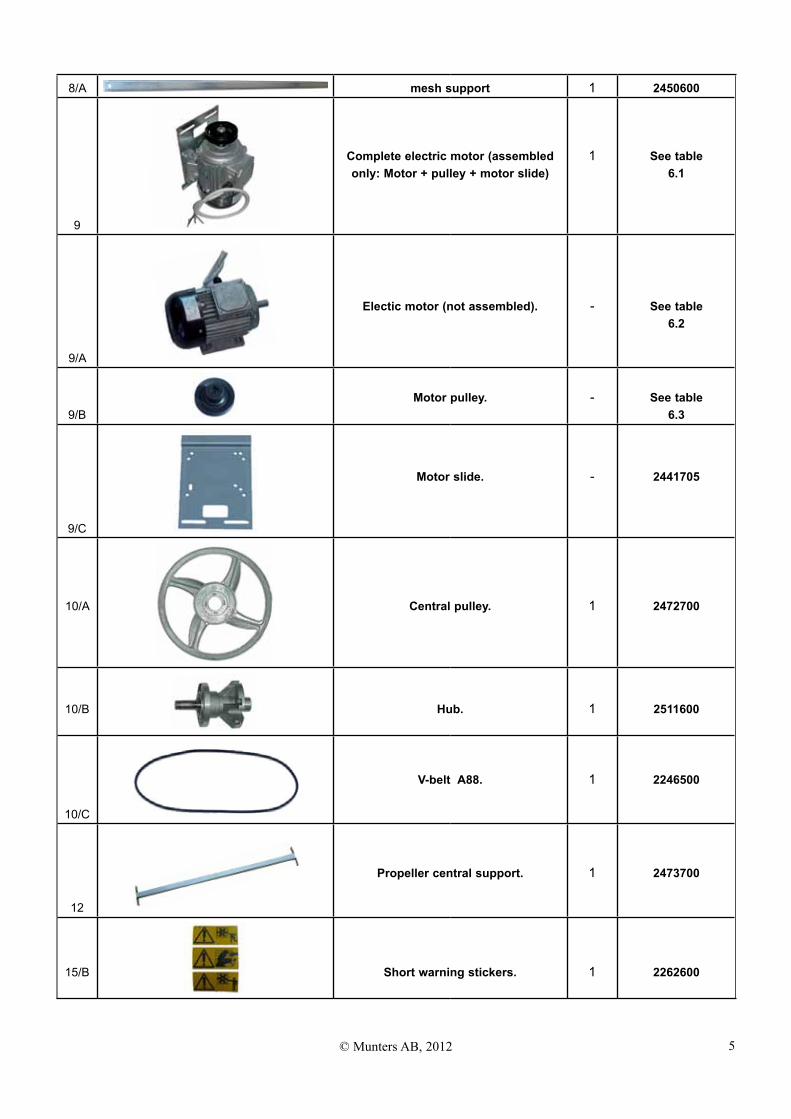
8/A mesh support 1 2450600
9
Complete electric motor (assembled only: Motor + pulley + motor slide)
1 See table 6.1
9/A
Electic motor (not assembled). - See table 6.2
9/BMotor pulley. - See table
6.3
9/C
Motor slide. - 2441705
10/A Central pulley. 1 2472700
10/B Hub. 1 2511600
10/C
V-belt A88. 1 2246500
12
Propeller central support. 1 2473700
15/B Short warning stickers. 1 2262600

6 © Munters AB, 2012
15/C
Warning on the sutter. 2 2262095
16/A Plastic safety protection for central pulley.
1 2267301
16/B Plastic safety protection for belt.
2 2267401
16/CPlasic safety protection for motor
pulley + fixing clip.1 2467350
16/ESelf tapping hex screw Ø 6.3 x 19
mm. 4 2278800
2. SPARE PARTS LIST foR CE PRoTECTIoN (oPTIoN)
2.1 SPARE PARTS LIST foR PyRAMIDAL SHAPE MESH foR CE PRoTECTIoN (oPTIoN)
17/A Pyramidal safety mesh. 1 2823713
17/B
B AA: metal clips to fix pyramidal safety
mesh B: self tapping hex screw Ø 6.3 X 19
mm.
6
6
2448600
2278800
7© Munters AB, 2012
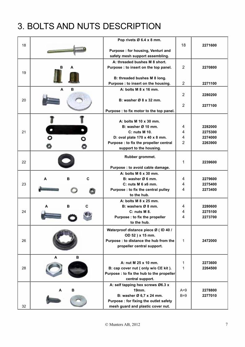
3. BoLTS AND NUTS DESCRIPTIoN
18Pop rivets Ø 6.4 x 8 mm.
Purpose : for housing, Venturi and safety mesh support assembling.
18 2271600
19B A
A: threaded bushes M 8 short. Purpose : to insert on the top panel.
B: threaded bushes M 8 long.
Purpose : to insert on the housing.
2
2
2270800
2271100
20
A B A: bolts M 8 x 16 mm.
B: washer Ø 8 x 32 mm.
Purpose : to fix motor to the top panel.
2
2
2280200
2277100
21
A: bolts M 10 x 30 mm. B: washer Ø 10 mm.
C: nuts M 10. D: oval plate 170 x 40 x 8 mm.
Purpose : to fix the propeller central support to the housing.
4442
2282000227530022740002263900
22 Rubber grommet.
Purpose : to avoid cable damage.
1 2239600
23A B C
A: bolts M 6 x 30 mm. B: washer Ø 6 mm. C: nuts M 6 x6 mm.
Purpose : to fix the central pulley to the hub.
444
227960022754002273400
24A B C
A: bolts M 8 x 25 mm. B: washers Ø 8 mm.
C: nuts M 8. Purpose : to fix the propeller
to the hub.
444
228060022751002273700
26
Waterproof distance piece Ø ( ID 40 / OD 52 ) x 15 mm.
Purpose : to distance the hub from the propeller central support.
1 2472000
28
A BA: nut M 25 x 10 mm.
B: cap cover nut ( only w/o CE kit ). Purpose : to fix the hub to the propeller
central support.
11
22736002264500
32
A BA: self tapping hex screws Ø6.3 x
19mm. B: washer Ø 6,7 x 24 mm.
Purpose : for fixing the outlet safety mesh guard and plastic cover nut.
A=9B=9
22788002277010
8 © Munters AB, 2012
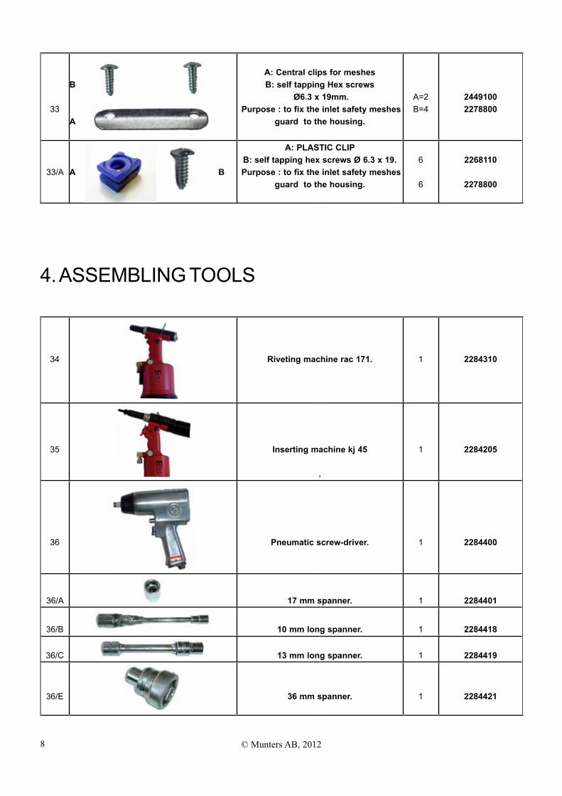
33
B
A
A: Central clips for meshes B: self tapping Hex screws
Ø6.3 x 19mm. Purpose : to fix the inlet safety meshes
guard to the housing.
A=2B=4
24491002278800
33/A A B
A: PLASTIC CLIP B: self tapping hex screws Ø 6.3 x 19.
Purpose : to fix the inlet safety meshes guard to the housing.
6
6
2268110
2278800
4. ASSEMBLING TooLS
34 Riveting machine rac 171. 1 2284310
35 Inserting machine kj 45
.
1 2284205
36 Pneumatic screw-driver. 1 2284400
36/A 17 mm spanner. 1 2284401
36/B 10 mm long spanner. 1 2284418
36/C 13 mm long spanner. 1 2284419
36/E 36 mm spanner. 1 2284421
9© Munters AB, 2012
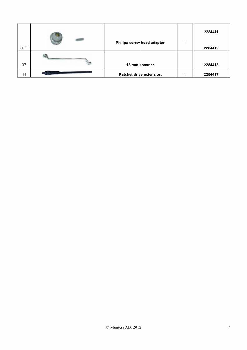
36/fPhilips screw head adaptor. 1
2284411
2284412
37 13 mm spanner. 2284413
41 Ratchet drive extension. 1 2284417
10 © Munters AB, 2012
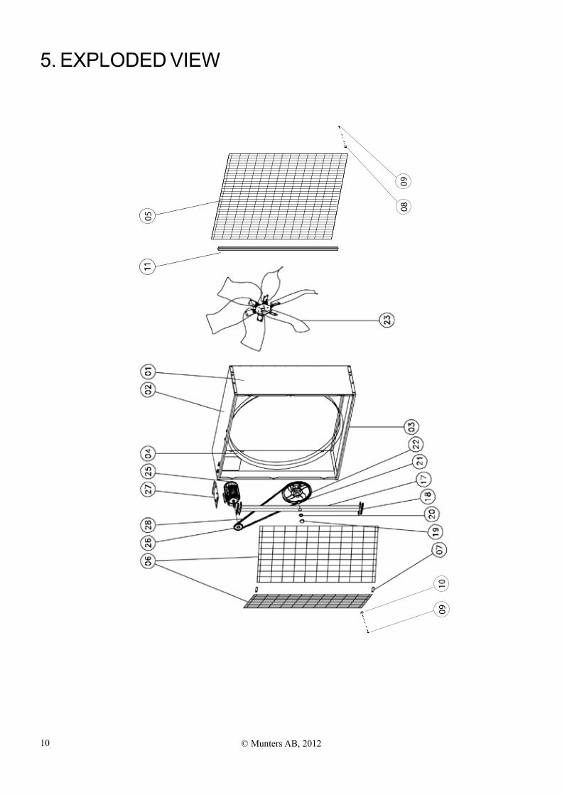
5. EXPLoDED VIEW
1011 11
05
0910
0809
11© Munters AB, 2012
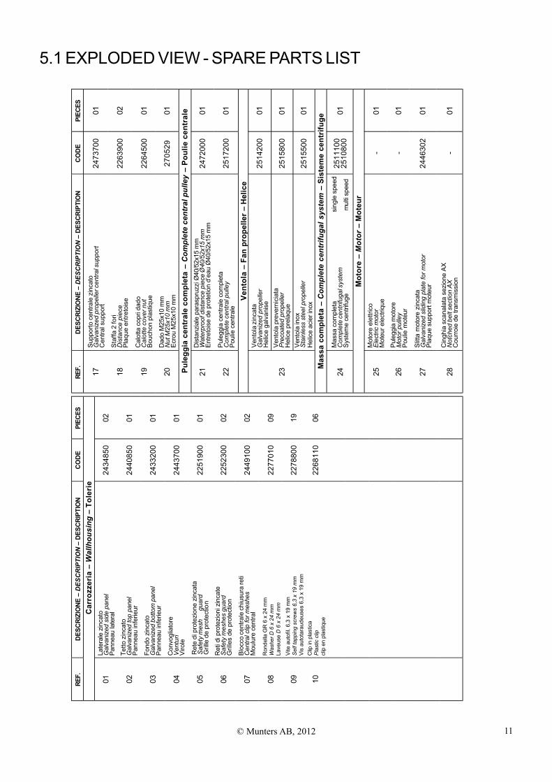
5.1 EXPLoDED VIEW - SPARE PARTS LIST RE
F.D
ESC
RIZ
ION
E–
DES
CR
IPTI
ON
–D
ESC
RIP
TIO
NC
OD
EPI
ECES
17Su
ppor
to c
entra
le z
inca
toG
alva
nize
d pr
opel
ler c
entra
l sup
port
Cen
tral s
uppo
rt24
7370
001
18S
taffa
2 fo
riD
ista
nce
piec
ePl
aque
ent
reto
ise
2263
900
02
19C
alot
ta c
opri
dado
Cal
otte
cov
er n
utBo
ucho
n pl
astiq
ue22
6450
001
20D
ado
M25
x10
mm
Nut
M25
x10
mm
Ecro
u M
25x1
0 m
m27
0529
01
Pule
ggia
cen
tral
e co
mpl
eta
–C
ompl
ete
cent
ral p
ulle
y –
Poul
ie c
entr
ale
21D
ista
nzia
le p
aras
pruz
zi Ø
40/5
2x15
mm
Wat
erpr
oof d
ista
nce
piec
e Ø
40/5
2x15
mm
Entre
tois
e de
pro
tetio
n d’
eau
Ø40
/52x
15 m
m24
7200
001
22Pu
legg
ia c
entra
le c
ompl
eta
Com
plet
e ce
ntra
l pul
ley
Poul
ie c
entra
le25
1720
001
Vent
ola
– Fa
n pr
opel
ler
– H
elic
e
23
Ven
tola
zin
cata
Gal
vani
zed
prop
elle
rH
elic
e ga
lvan
ise
2514
200
01
2515
800
01
2515
500
01
Mas
sa c
ompl
eta
–C
ompl
ete
cent
rifug
al s
yste
m –
Sis
tem
e ce
ntri
fuge
24M
assa
com
plet
a
s
ingl
e sp
eed
Com
plet
e ce
ntrif
ugal
sys
tem
Syst
eme
cent
rifug
e
m
ulti
spee
d25
1110
025
1080
001
Mot
ore
–M
otor
– M
oteu
r
25M
otor
e el
ettri
coEl
ectri
c m
otor
Mot
eur e
lect
rique
-01
26Pu
legg
ia m
otor
eM
otor
pul
ley
Poul
ie m
oteu
r-
01
27Sl
itta
mot
ore
zinc
ata
Gal
vani
zed
slid
ing
plat
e fo
r mot
orPl
aque
sup
port
mot
eur
2446
302
01
28C
ingh
ia s
cana
lata
sez
ione
AX
Not
ched
bel
t sec
tion
AX
Cou
rroie
de
trans
mis
sion
-01
Vent
ola
prev
erni
ciat
aPr
ecoa
ted
prop
elle
rH
elic
e pr
elaq
ueVe
ntol
a in
oxSt
ainl
ess
stee
l pro
pelle
rH
elic
e ac
ier i
nox
REF.
DES
CR
IZIO
NE–
DES
CR
IPTI
ON
–D
ESC
RIP
TIO
NC
OD
EPI
ECES
Car
rozz
eria
–W
allh
ousi
ng–
Tole
rie
01La
tera
le z
inca
toG
alva
nize
d si
de p
anel
Pann
eau
late
ral
2434
850
02
02Te
tto z
inca
toG
alva
nize
d to
p pa
nel
Pann
eau
infe
rieur
2440
850
01
03Fo
ndo
zinc
ato
Gal
vani
zed
botto
m p
anel
Pann
eau
infe
rieur
2433
200
01
04C
onvo
glia
tore
Ven
turi
Viro
le24
4370
001
0522
5190
001
06R
eti d
i pro
tezi
oni z
inca
teS
afet
y m
eshe
s gu
ard
Gril
les
de p
rote
ctio
n22
5230
002
07Bl
occo
cen
trale
chi
usur
a re
tiC
entra
l clip
for m
eshe
sM
oulu
re c
entra
l24
4910
002
08R
onde
lla G
R 6
x 2
4 m
mW
ashe
r D 6
x 2
4 m
mLa
veus
e D
6 x
24
mm
2277
010
09
09Vi
te a
utof
il. 6
,3 x
19
mm
Self
tapp
ing
scre
ws
6,3
x 19
mm
Vis
auto
tara
udeu
ses
6,3
x 19
mm
2278
800
19
10C
lip in
pla
stic
aPl
astic
clip
clip
en
plas
tique
2268
110
06
Ret
e di
pro
tezi
one
zinc
ata
Saf
ety
mes
h gu
ard
Gril
le d
e pr
otec
tion
12 © Munters AB, 2012
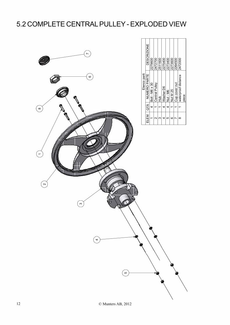
5.2 CoMPLETE CENTRAL PULLEy - EXPLoDED VIEW
14
Bolt
-M6
x30
2279
600
21
Cen
tralP
ulle
y24
7270
03
1H
ub25
1160
04
4W
ashe
rD6
2275
400
54
Nut
-M6
2273
400
61
Nut
M25
2273
600
71
Cup
cove
rnut
2264
500
81
wat
erpr
oofd
ista
nce
2472
000
piec
e
Ele
nco
parti
ELE
M.
QTÀ
NU
ME
RO
PAR
TED
ESC
RIZ
ION
E
12
3
4
5
67
8
13© Munters AB, 2012
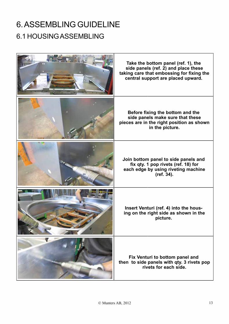
6. ASSEMBLING GUIDELINE6.1 HoUSING ASSEMBLING
Take the bottom panel (ref. 1), the side panels (ref. 2) and place these
taking care that embossing for fixing the central support are placed upward.
Before fixing the bottom and the side panels make sure that these
pieces are in the right position as shown in the picture.
Join bottom panel to side panels and fix qty. 1 pop rivets (ref. 18) for
each edge by using riveting machine (ref. 34).
Insert Venturi (ref. 4) into the hous- ing on the right side as shown in the
picture.
Fix Venturi to bottom panel and then to side panels with qty. 3 rivets pop
rivets for each side.
14 © Munters AB, 2012
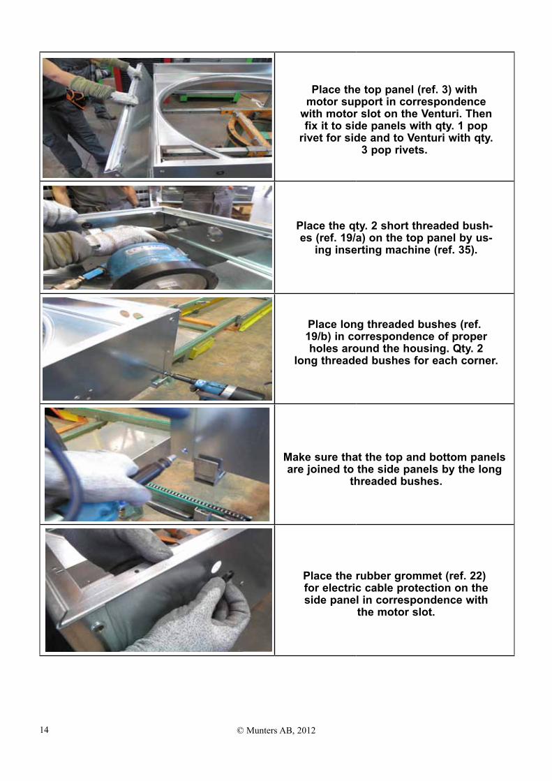
Place the top panel (ref. 3) with motor support in correspondence
with motor slot on the Venturi. Then fix it to side panels with qty. 1 pop
rivet for side and to Venturi with qty. 3 pop rivets.
Place the qty. 2 short threaded bush- es (ref. 19/a) on the top panel by us-
ing inserting machine (ref. 35).
Place long threaded bushes (ref. 19/b) in correspondence of proper holes around the housing. Qty. 2
long threaded bushes for each corner.
Make sure that the top and bottom panels are joined to the side panels by the long
threaded bushes.
Place the rubber grommet (ref. 22) for electric cable protection on the side panel in correspondence with
the motor slot.
15© Munters AB, 2012
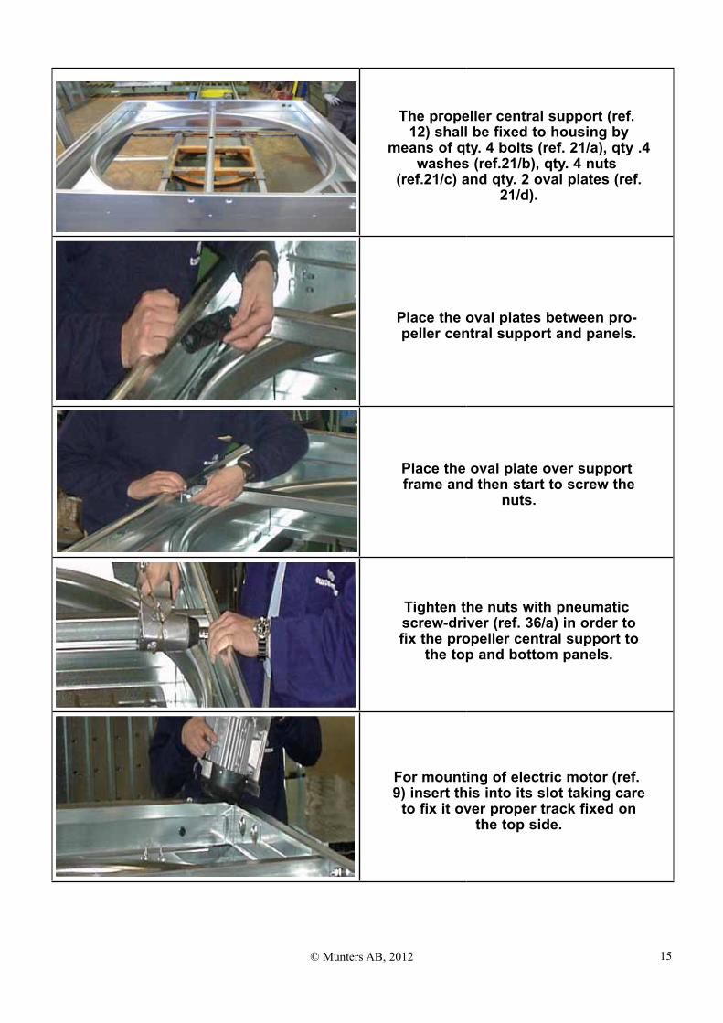
The propeller central support (ref. 12) shall be fixed to housing by
means of qty. 4 bolts (ref. 21/a), qty .4 washes (ref.21/b), qty. 4 nuts
(ref.21/c) and qty. 2 oval plates (ref. 21/d).
Place the oval plates between pro- peller central support and panels.
Place the oval plate over support frame and then start to screw the
nuts.
Tighten the nuts with pneumatic screw-driver (ref. 36/a) in order to fix the propeller central support to
the top and bottom panels.
For mounting of electric motor (ref. 9) insert this into its slot taking care
to fix it over proper track fixed on the top side.
16 © Munters AB, 2012
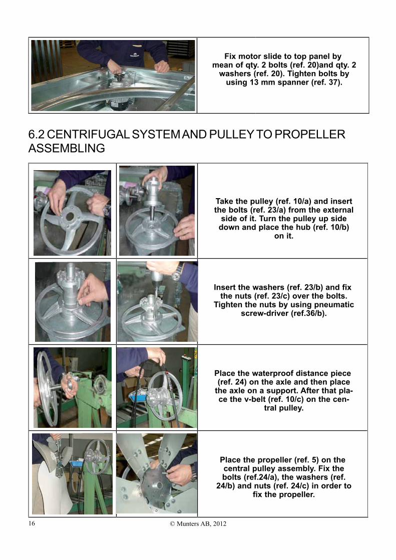
Fix motor slide to top panel by mean of qty. 2 bolts (ref. 20)and qty. 2
washers (ref. 20). Tighten bolts by using 13 mm spanner (ref. 37).
6.2 CENTRIfUGAL SySTEM AND PULLEy To PRoPELLER ASSEMBLING
Take the pulley (ref. 10/a) and insert the bolts (ref. 23/a) from the external
side of it. Turn the pulley up side down and place the hub (ref. 10/b)
on it.
Insert the washers (ref. 23/b) and fix the nuts (ref. 23/c) over the bolts.
Tighten the nuts by using pneumatic screw-driver (ref.36/b).
Place the waterproof distance piece (ref. 24) on the axle and then place
the axle on a support. After that pla- ce the v-belt (ref. 10/c) on the cen-
tral pulley.
Place the propeller (ref. 5) on the central pulley assembly. Fix the bolts (ref.24/a), the washers (ref.
24/b) and nuts (ref. 24/c) in order to fix the propeller.
17© Munters AB, 2012
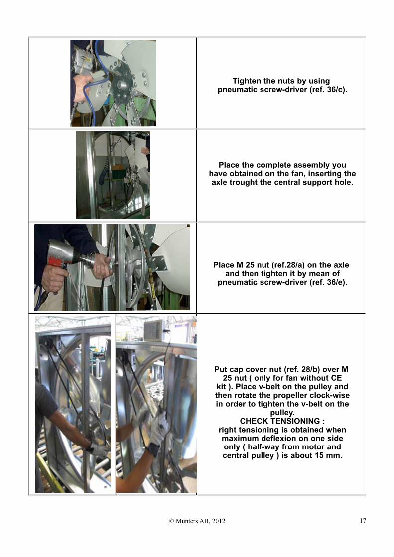
Tighten the nuts by using pneumatic screw-driver (ref. 36/c).
Place the complete assembly you have obtained on the fan, inserting the axle trought the central support hole.
Place M 25 nut (ref.28/a) on the axle and then tighten it by mean of
pneumatic screw-driver (ref. 36/e).
Put cap cover nut (ref. 28/b) over M 25 nut ( only for fan without CE
kit ). Place v-belt on the pulley and then rotate the propeller clock-wise in order to tighten the v-belt on the
pulley. CHECK TENSIONING :
right tensioning is obtained when maximum deflexion on one side only ( half-way from motor and central pulley ) is about 15 mm.
18 © Munters AB, 2012
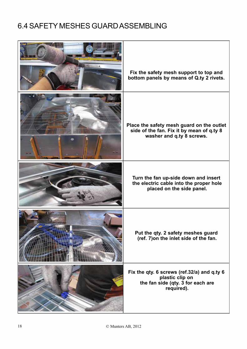
Fix the safety mesh support to top and bottom panels by means of Q.ty 2 rivets.
Place the safety mesh guard on the outlet side of the fan. Fix it by mean of q.ty 8
washer and q.ty 8 screws.
Turn the fan up-side down and insert the electric cable into the proper hole
placed on the side panel.
Put the qty. 2 safety meshes guard (ref. 7)on the inlet side of the fan.
Fix the qty. 6 screws (ref.32/a) and q.ty 6 plastic clip on
the fan side (qty. 3 for each are required).
6.4 SAfETy MESHES GUARD ASSEMBLING

19© Munters AB, 2012
6.5 CE kIT ASSEMBLING
Fix the screws (ref. 32/a) with the central clips (ref.33) in correspon- dence of the propeller central sup-
port on the top panel and the bottom panel.
Fix the screw (ref. 32/a) with the washer (ref. 32/b) into the central
pulley axle. Fix all the components by using the pneumatic screw-driver
(ref. 36/f).
Before assembling the safety meshs complete the CE kit. Join the plastic safety protection for central pulley (ref.16/a) with
plastic safety protection for the v-belt (ref.16/b)
Place the plastic safety protection for the motor pulley in the motor corner. (make
sure that the plastic square pins are inserted in the proper housing holes).
Join the plastic safety protection for the motor pulley.

20 © Munters AB, 2012
Put the assembled CE plastic kit protection as shown in the picture (make sure that the groove of the plastic safety
protection for the v-belt are centered along the v-belt)
Follow the safety mesh guard assembling procedures and then fix the complete
assembled you have obtained by mean of qty.1 screw(ref. 32/a).
21© Munters AB, 2012
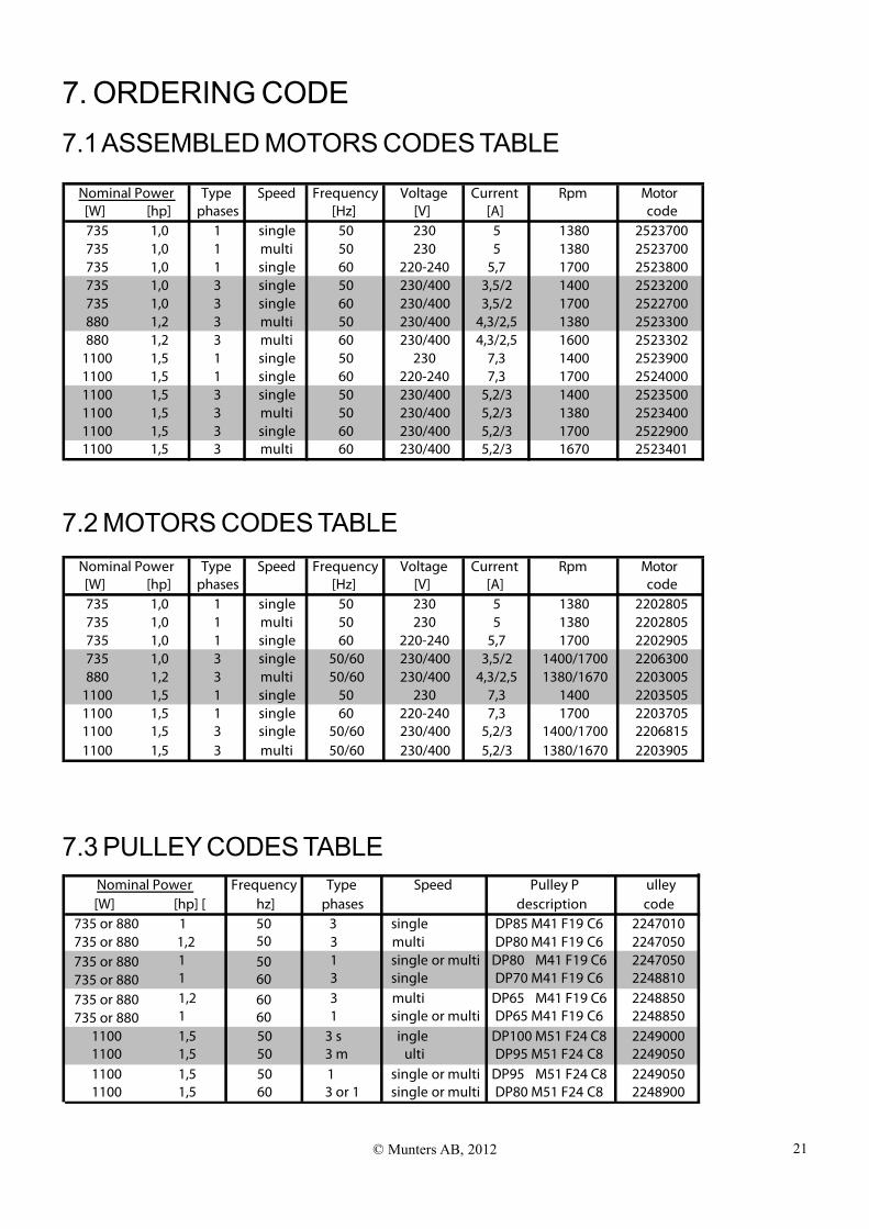
7. oRDERING CoDE7.1 ASSEMBLED MoToRS CoDES TABLE
Type Speed Frequency Voltage Current Rpm Motor[W] [hp] phases [Hz] [V] [A] code735 1,0 1 single 50 230 5 1380 2523700735 1,0 1 multi 50 230 5 1380 2523700735 1,0 1 single 60 220-240 5,7 1700 2523800735 1,0 3 single 50 230/400 3,5/2 1400 2523200735 1,0 3 single 60 230/400 3,5/2 1700 2522700880 1,2 3 multi 50 230/400 4,3/2,5 1380 2523300880 1,2 3 multi 60 230/400 4,3/2,5 1600 2523302
1100 1,5 1 single 50 230 7,3 1400 25239001100 1,5 1 single 60 220-240 7,3 1700 25240001100 1,5 3 single 50 230/400 5,2/3 1400 25235001100 1,5 3 multi 50 230/400 5,2/3 1380 25234001100 1,5 3 single 60 230/400 5,2/3 1700 25229001100 1,5 3 multi 60 230/400 5,2/3 1670 2523401
Nominal Power
7.2 MoToRS CoDES TABLE
7.3 PULLEy CoDES TABLE
Type Speed Frequency Voltage Current Rpm Motor[W] [hp] phases [Hz] [V] [A] code735 1,0 1 single 50 230 5 1380 2202805735 1,0 1 multi 50 230 5 1380 2202805735 1,0 1 single 60 220-240 5,7 1700 2202905735 1,0 3 single 50/60 230/400 3,5/2 1400/1700 2206300880 1,2 3 multi 50/60 230/400 4,3/2,5 1380/1670 2203005
1100 1,5 1 single 50 230 7,3 1400 22035051100 1,5 1 single 60 220-240 7,3 1700 22037051100 1,5 3 single 50/60 230/400 5,2/3 1400/1700 22068151100 1,5 3 multi 50/60 230/400 5,2/3 1380/1670 2203905
Nominal Power
Frequency Type Speed Pulley P ulley[W] [hp] [ hz] phases description code
735 or 880
735 or 880
1 50
50 50
60 60 60
3 single DP85 M41 F19 C6 2247010735 or 880
735 or 880735 or 880735 or 880
1,2 3 multi DP80 M41 F19 C6 22470501 1 single or multi DP80 M41 F19 C6 22470501 3 single DP70 M41 F19 C6 22488101,2 3 multi DP65 M41 F19 C6 22488501 1 single or multi DP65 M41 F19 C6 2248850
Nominal Power
1100 1,5 50 3 s ingle DP100 M51 F24 C8 22490001100 1,5 50 3 m ulti DP95 M51 F24 C8 22490501100 1,5 50 1 single or multi DP95 M51 F24 C8 22490501100 1,5 60 3 or 1 single or multi DP80 M51 F24 C8 2248900

22 © Munters AB, 2012
Munters Europe AB, HumiCool Division, Isafjordsgatan 1, P.o. Box 1150, SE-164 26 kista, Sweden. Phone +46 08 626 63 00, fax +46 8 754 56 66.
Munters Italy S.p.A., Strada Piani 2, IT-18027 Chiusavecchia, Italy. Phone +39 0183 52 11, fax +39 0183 521 333. www.munters.com
Australia Munters Pty Limited, Phone +61 2 6025 6422, Brazil Munters Brasil Industria e Comercio Ltda, Phone +55 11 5054 0150, Canada Munters Incorporated, Phone + 1 905 858 5894, China Munters Air Treatment Equipment (Beijing) Co., Ltd., Phone +86 10 80 481 121, Denmark Munters Turbovent, Phone +45 98623311, Finland Munters oy, Phone +358 9 83 86 030,
France Munters france S.A., Phone +33 1 34 11 57 50, Germany Munters Euroform GmbH, Phone +49 241 89 0 00, India Munters India, Phone +91 20 30522520, Indonesia Munters Phone +62 21 9105446-7, Italy Munters Italy S.p.A., Chiusavecchia Phone +39 0183-52 11, Munters Italy S.p.A., Mondovì Phone +39 0174 560 600 Japan Munters k.k., Phone +81 3
5970 0021, Kingdom of Saudi Arabia and Middle East Hawa Munters, Phone +966 1 477 15 14, Korea Munters korea Co,. Ltd, Phone +82 2 761 8701, Mexico Munters Mexico Phone +52 722 270 40 30, Russia Munters Europe AB, Phone +7 812 4485740, Singapore Munters Pte Ltd +65 744 6828 South Africa and Sub-Sahara Countries Munters (Pty) Ltd, Phone +27
11 971 9700, Spain Munters Spain S.A., Phone +34 91-640 09 02, Sweden Munters Europe AB, Phone +46 8 626 63 00, Thailand Munters (Thailand) Co. Ltd., Phone +66 2 645 2708-12, United Kingdom Munters Ltd, Phone +44 845 644 3980, USA Munters Corporation Fort Myers, Phone
+1 239 936 1555, Munters Corporation Mason, Phone +1 888 335 0100, Vietnam Munters Vietnam Phone +84 8 825 6838 Export & Other countries Munters Europe AB, Phone +46 8 626 63 00
Munters reserves the right to make alterations to specifications, quantities, etc., for production or other reasons, subsequent to publication.© Munters AB, 2009
EMS 50 is developed and produced by Munters S.p.A, Italy
HC
/MIT
/Um
GB
-190
6-02
/12
Mun
ters
Ital
y