spares manual - glasdon
TRANSCRIPT

TURBOCAST 800 ™
Spares Manual
ENGLISH (UK) VERSIONOCTOBER 2014
ORIGINAL INSTRUCTIONS
Towable Grit/Salt Spreader
Glasdon U.K. LimitedPreston New RoadBLACKPOOLLancashireFY4 4ULTel: (01253) 600410Fax: (01253) 792558e-mail: [email protected]

Spares Manual
CONTENTS PAGE
1
Thank you for purchasing a Glasdon Turbocast 800 Towable Grit/Salt Spreader.This manual contains important information for how your product is put together and how to maintain or replace parts during its lifetime. Your product has been designed to last for many years, however regular inspection and replacement of wearing parts may be required from time to time to keep your machine in prime working order. It is recommended that the machine is throughly inspected and serviced prior to storing the machine away for extended periods e.g. at the end of the Winter season - so that your machine is ready to be used as soon as conditions demand.
SECTION 1
SECTION 2
SECTION 3
SECTION 4
SPARES KITS - TOOLS & CONTENTS
PARTS LIST
EXPLODED VIEWSFIG 1. Ball Hitch AssemblyFIG 2. Pin Hitch AssemblyFIG 3. Mudguard / Cover Flap AssemblyFIG 4. Drive Cover and Chain Tensioner AssemblyFIG 5. Chains AssemblyFIG 6. Spinner Shaft Sprocket AssemblyFIG 7. Agitator Shaft Assembly - Sprockets and ClutchFIG 8. Agitator Shaft Assembly - Cams and BearingsFIG 9. Clutch and Cam Handle AssemblyFIG. 10 Spinner Plate / Spread Limiter Assembly FIG. 11 Wheel and Free Hub AssemblyFIG. 12 Drive Shaft Hub Sprocket AssemblyFIG. 13 Agitator Mat and Fingers AssemblyFIG. 14 Lighting AssemblyFIG. 15 Flow Control AssemblyFIG. 16 Drive Wheel Assembly
MECHANICSFIG 17. Drive SystemFIG 18. Agitation SystemFIG 19. Flow Control Mechanism
2
7
1010101112131414151516161717181819
20202122

1 Spares Kits - Tools & Contents
2
KITS: TOOLS REQUIRED: KIT CONTENTS: FIGURE:
KIT 1. Spare Pin Hitch
Kit.
19mm 17mm 2 x 17mm & 2 x 19mm Socket Set
+ or
163164 (x2)
169210211 212213
214 (x2)215 (x4)
2
KIT 2. Spare Ball Hitch
Kit.
19mm 17mm 2 x 17mm & 2 x 19mm Socket Set
+ or
155156157
162 (x2)163 (x3)164 (x6)
169
1
KIT 3. Chain for
Agitation to Spinner Plate.
103 5
KIT 4. Chain for Main
Shaft to Agitation System.
104 5
KIT 5. Spare Chain Tensioning Kit
(Pair).
5mm
+
100 (x2)101 (x4)111 (x2)113 (x4)116 (x4)
4
KIT 6. Spare Agitator Shaft Assembly
Kit.
17mm 2 x 17mm & 2 x 13mm 6mm 13mm Socket Set
or + +
6768 (x10)69 (x2)70 (x2)83 (x20)84 (x20)85 (x20)86 (x4)87 (x4)88 (x4)
7
KIT 7. Spare Agitator
Cam Kit.
13mm 13mm 6mm Socket
or +68 (x2)83 (x4)84 (x4)85 (x4)
7

3
1 Spares Kits - Tools & Contents
KITS: TOOLS REQUIRED: KIT CONTENTS: FIGURE:
KIT 8. Spare Agitator Finger & Roller
Kit.
10mm 10mm 5mm Socket
or +
118122123124125
12
KIT 9. Spare Agitator
Mat Kit.
10mm 10mm 5mm Socket
or +
117122 (x5)123 (x5)124 (x5)125 (x5)128 (x2)129 (x2)
12
KIT 10. Spare 45 Tooth
Sprocket Kit.
10mm 10mm 5mm Socket
or +718990
6
KIT 11. Spare 15 Tooth Sprocket Kit (25
Bore).
5mm 72737491
6
KIT 12. Spare 38 Tooth
Sprocket Kit.
10mm 10mm Socket
or31314
11
KIT 13. Spare 15 Tooth Sprocket Kit (26
Bore).
10mm 10mm Socket
or273536
5
4
1 Spares Kits - Tools & Contents
KITS: TOOLS REQUIRED: KIT CONTENTS: FIGURE:
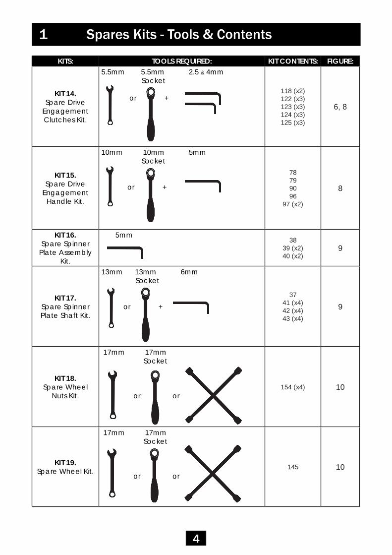
KIT 14. Spare Drive
Engagement Clutches Kit.
5.5mm 5.5mm 2.5 & 4mm Socket
or +118 (x2)122 (x3)123 (x3)124 (x3)125 (x3)
6, 8
KIT 15. Spare Drive
Engagement Handle Kit.
10mm 10mm 5mm Socket
or +
78799096
97 (x2)
8
KIT 16. Spare Spinner
Plate Assembly Kit.
5mm38
39 (x2)40 (x2)
9
KIT 17. Spare Spinner Plate Shaft Kit.
13mm 13mm 6mm Socket
or +37
41 (x4)42 (x4)43 (x4)
9
KIT 18. Spare Wheel
Nuts Kit.
17mm 17mm Socket
or or154 (x4) 10
KIT 19. Spare Wheel Kit.
17mm 17mm Socket
or or145 10

5
1 Spares Kits - Tools & Contents
KITS: TOOLS REQUIRED: KIT CONTENTS: FIGURE:
KIT 20. Spare Electrical
Extension Kit.-
118122123124125
-
KIT 21. Spare Light
Cluster Set Kit.
10mm 10mm 5mm Phillips Socket
or + +179180
188 (x4)189 (x4)
13
KIT 22. Spare Left Hand Light Cluster Kit.
10mm 10mm Phillips Socket
or +180
188 (x2)189 (x2)
13
KIT 23. Spare Right Hand Light Cluster Kit.
10mm 10mm Phillips Socket
or +179
188 (x2)189 (x2)
13
KIT 24. Spare Fog Light
Kit.
10mm 10mm Phillips Socket
or +181
188 (x2)189 (x2)
13
KIT 25. Spare Spread
Limiter Kit.
17mm 17mm Socket
or
170172
173 (x4)175176
177 (x2)
9

6
1 Spares Kits - Tools & Contents
KITS: TOOLS REQUIRED: KIT CONTENTS: FIGURE:
KIT 26. Spare Drive
Wheel Assembly Kit.
17mm 2 x 17mm & 2 x 10mm 10mm Socket Set
or +
20212224
28 (x2)29 (x4)
30
16
KIT 27. Spare PVC
Hopper Cover Kit.
- 207 -
Prior to attempting replacement of any parts please ensure you have a good understanding of how the kit you wish to fit should be fitted to the machine. Check that you have the correct tools and expertise to carry out the replacement.
The Exploded views in Section 3 give a complete overview of all the assemblies which make up your gritting machine. Below each drawing description there is listed the kit numbers relevant to that particular figure.
In addition to an exploded view showing how the parts of the machine are put together - each illustration also includes (where applicable) recommended maintenance that should be carried out whilst the machine is part disassembled and so parts are fully accessible. Please carry out these maintenance procedures as these will help ensure the long lifespan of the machine.

PART NO.
PART DESCRIPTION PART NO.
PART DESCRIPTION
1 Main Chassis Assembly 41 M8 x 20mm Hex Head Screw S/S2 Axle Bearing 42 Nyloc Nut M8 S/S3 38 Tooth Sprocket (Main Shaft) 43 Washer Plain M8 S/S4 Main Shaft 44 Lead Screw Nut5 Hub – Drive Side 45 Flow Mechanism Bush6 Hub – Free Wheel Side 46 Flow Mechansim Tube Assembly7 Hub Bearing 25 47 Lead Screw8 Hub Bearing 30 48 Handwheel9 Hub Cap 49 M6 x 25mm Socket Cap Screw S/S
10 M12 x 50mm Skt Bt Head S/S 50 S/S Washer M6 x 14mm O.D11 N12 Nylock Nut S/S 51 M6 Nyloc Nut Stainless Steel12 M12 Form B Flat Washer 52 M3 x 20mm SKT Cap Head Screw S/S13 M6 x 100mm Hex Head Screw S/S 53 M3 Washer S/S14 M6 Nylock Nut S/S 54 M3 Nyloc Nut S/S15 Hex Head Screw M8 x 65mm Bolt BZP 55 M4 x 16mm SKT Cap Head Screw S/S16 M8 Nylock Nut Hex Head BZP 56 M4 x 40mm SKT Cap Head Screw S/S17 M20 Castle Nut 57 M4 Washer 9mm O.D. S/S18 Plain Washer M20 58 Nut - M4 - Nyloc S/S19 Split Pin Ø3mm x 30mm 59 Hopper - Yellow20 Drive Wheel 60 Nylon Spacer - ID 10.2mm21 Drive Wheel Bearing 61 Hopper Funnel Shelf22 Drive Wheel Adaptor 62 M6 x 13mm Post Mould Insert23 Drive Shaft 63 M10 Nyloc Nut M10 S/S24 M6 Three Point Handwheel Orange 64 Washer Plain M10 S/S25 Adjuster Bearing diam. 25mm 65 M10 x 60 SKT BT Screw S/S26 See Part 25. 66 M6 x 20mm Hex Head Screw S/S27 15 Tooth Sprocket (Spinner Shaft) 67 Agitator Shaft Assembly28 M6 x 20mm Hex Head Screw S/S 68 Agitator Cam29 M6 Spring Washer S/S 69 Adjuster Bearing diam. 25mm30 Screw - M6 x 16mm Hex Head S/S 70 I/Zinc & P/Coat of Adjuster Bearing31 M10 Nyloc Nut M10 S/S 71 45 Tooth Sprocket (Agitation Shaft)32 Washer Plain M10 S/S 72 15 Tooth Sprocket (Agitation Shaft)33 10.3 x 20.6 x 3.2mm Nylon Washer 73 Sprocket Bearing34 M6 x 18 x 1.5mm Washer S/S 74 Clutch Collet35 M6 X 60mm Hex Head Screw S/S 75 Castle Dog Clutch36 M6 Nyloc Nut Stainless Steel 76 Clutch Spacer37 Spinner Shaft 77 Dog Clutch Sleeve38 Turbocast 800 Spinner Plate 78 Cam Handle39 Turbocast 800 Spinner Bearing 79 Eye Stud (Cam Handle)40 Two Piece Collar 80 S/S Compression Spring - 9.5mm
7
2 Parts List

PART NO.
PART DESCRIPTION PART NO.
PART DESCRIPTION
81 Agitator Bearing Cover R/H 121 Mat Clamp82 Agitator Bearing Cover L/H 122 M6x16mm Socket Button Screw S/S83 M8 x 40mm Hex Head Bolt S/S 123 S/S Washer M6 x 14mm O.D84 Washer Plain M8 S/S 124 M6 Nyloc Nut S/S85 Nyloc Nut M8 S/S 125 Black Nylon Spacer86 Screw Set Hex Head M10 x 25mm S/S 126 M8 x 20mm Hex Head Screw S/S87 M10 Nyloc Nut M10 S/S 127 Washer Plain M8 S/S88 Washer Plain M10 S/S 128 M6 Penny Washer S/S89 M6 x 100mm Hex Head Screw BZP 129 M6 x 20mm Hex Head Screw S/S90 M6 Nyloc Nut S/S 130 Mudguard R/H91 M5 x 10mm Grub Screw 131 Mudguard L/H92 M4 x 10mm CSK Screw S/S 132 Clutch Access Flap L/H93 M3 x 40mm SKT BT Screw BZP 133 Clutch Access Flap R/H94 M3 Nyloc Nut S/S 134 Single Point Cam38 Steel95 M3 Washer S/S 135 Toothed Lock Washer96 M6 x 20mm Socket Button Screw S/S 136 Wing Knob Polymide Housing97 S/S Washer M6 x 14mm O.D 137 Wing Knob - Lock Insert98 M6 x 16mm Socket Head Screw S/S 138 Flat External Seal99 M6 x 13mm Post Mould Insert 139 O-Ring for Wing Lock Assembly
100 Chain Tensioner 140 S/S Washer M6 x 14mm O.D101 10.2 x 20 x 12mm Nylon 66 141 M6 x 12mm S/S Button Head102 Tensioner Bracket 142 75mm Hinge S/S Clutch Access Flap103 S/S Chain Pitch 110 c/w Connectors 143 Ashtray Retaining Bracket104 S/S Chain Pitch 83 c/w Connectors 144 Spray Suppression Mud Flap105 Hopper Underside Plate R/H 145 Wheel Assembly106 Hopper Underside Plate L/H 146 Rivet 4.8x18x10mm Black Alu107 Right Hand Chassis Cover 147 M5 x 16 SKT BT Screw S/S108 Left Hand Chassis Cover 148 M5 Nyloc Nut S/S109 Hopper Front Side Panel 149 M5 x 12.5 x 1mm Washer S/S110 Hopper Rear Side Panel 150 Rivet 4x11.5 S/S111 Split Pin 2.5 x 40mm S/S 151 M6 x 20 Skt Cap Screw S/S112 M6 x 50mm Hex Head Screw S/S 152 M6 Nyloc Nut S/S113 S/S Washer M6 x 14mm O.D 153 S/S Washer M6 x 14mm O.D114 M6 Nyloc Nut S/S 154 Wheel Nut Metric115 M6 x 20mm Hex Head Screw S/S 155 Tow Bar Hitch116 M6 x 20mm Hex Head Screw S/S 156 Coupling U/B Cast 50mm Ball H/D117 Agitator Mat 157 ISCP200 Secondary Break Cable118 Agitator Finger 158 Tow Bar119 Agitator Hinge 159 Jockey Wheel Spacer120 Agitator Hinge Rod 8mm x 400mm S/S 160 Jockey Wheel Clamp
8
2 Parts List

PART NO.
PART DESCRIPTION PART NO.
PART DESCRIPTION
161 Jockey Wheel 201 Drive Instructions External Sticker162 M12 x 120 Hex Head Bolt S/S 202 Drive Instructions Internal Sticker163 M12 Nylock Nut S/S 203 Polycarb Plaque “Spreading"164 M12 A2 Form B Flat Washer 204 Data Plate S/S 1.5mm165 M10 x 35mm Hex Head S/S 205 6x25mm Torx Pan Head Screw S/S166 M10 Nyloc Nut M10 S/S 206 Bulbex Rivet - Dyed Black Top167 M10 Washer S/S 207 Hopper Cover - Black PVC168 Bolt Hex Head M10 x 60mm S/S 208 Instruction Leaflet169 M12 x 80 Hex Head Bolt S/S 209 CE Certificate170 R/M Limiter OPTIONAL EXTRAS171 Limiter Bracket 210 Unbraked Towing Eye172 Limiter Handwheel 211 Towbar Eye Hitch Extension173 Reflector - 70 x 25mm Yellow 212 M10 X 100 Hex Head Bolt S/S174 6x25mm Torx Pan Head Screw S/S 213 Setscrew M10 x 50 Hex Head Bolt S/S175 M10 X 100 Hex Head Bolt S/S 214 M10 Nyloc Nut M10 S/S176 M10 Nyloc Nut M10 S/S 215 Washer Plain M10 S/S177 Washer Plain M10 S/S178 Cable, DC Connectors & 7 Pin Socket179 Light Cluster LHS180 Light Cluster RHS (with Fog Connector)181 Fog Light182 Red Triangular Reflectors183 Clear 90 x 40 Rectangle Reflector184 Amber Round Reflector185 2.3m Plug to Plug Straight Cable186 Wiring Cover Plate187 5 x 50 Self Tap Cross Head Pozi S/S188 M5 Nyloc Nut S/S189 M5 x 12.5 x 1mm Washer S/S190 4.8 x 32 Self Tap Cross Head Pozi S/S191 6x25mm Torx Pan Head Screw S/S192 S/A Vyl Stk “20”193 Oval Badge Glasdon194 Polycrown Turbocast 800195 Instruction & Maintenance Plaque196 Hitch Instructions Plaque197 Aperture Adjustment Wheel Plaque198 Handle Tree Clip199 Speed Adjustment Instructions Plaque200 Spread Limiter Instructions Plaque
9
2 Parts List

10
3 Exploded ViewsFIG. 1 Ball Hitch Assembly(Kit 2)
FIG. 2 Pin Hitch Assembly(Kit 1)

11
3 Exploded ViewsFIG. 3 Mudguard / Cover Flap Assembly

12
3 Exploded ViewsFIG. 4 Drive Cover and Chain Tensioner Assembly(Kit 3, 4, 5)

3 Exploded ViewsFIG. 5 Chains Assembly(Kit 3, 4)
13
Chain for Agitation to Spinner Plate.
Chain for Main Shaft to Agitation System.

14
3 Exploded Views
364
35
27
FIG. 6 Spinner Shaft Sprocket Assembly(Kit 13)
FIG. 7 Agitator Shaft Assembly - Sprockets and Clutch(Kit 10, 11, 14)

15
3 Exploded ViewsFIG. 8 Agitator Shaft Assembly - Cams and Bearings(Kit 6, 7)
FIG. 9 Clutch and Cam Handle Assembly(Kit 14, 15)
16
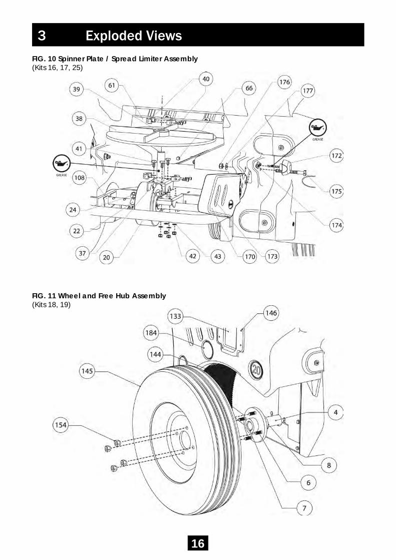
3 Exploded ViewsFIG. 10 Spinner Plate / Spread Limiter Assembly(Kits 16, 17, 25)
FIG. 11 Wheel and Free Hub Assembly(Kits 18, 19)

17
3 Exploded ViewsFIG. 12 Drive Shaft Hub Sprocket Assembly(Kit 12)
FIG. 13 Agitator Mat and Fingers Assembly(Kit 8, 9)

3 Exploded Views
18
FIG. 14 Lighting Assembly(Kit 21, 22, 23)
FIG. 15 Flow Control Assembly
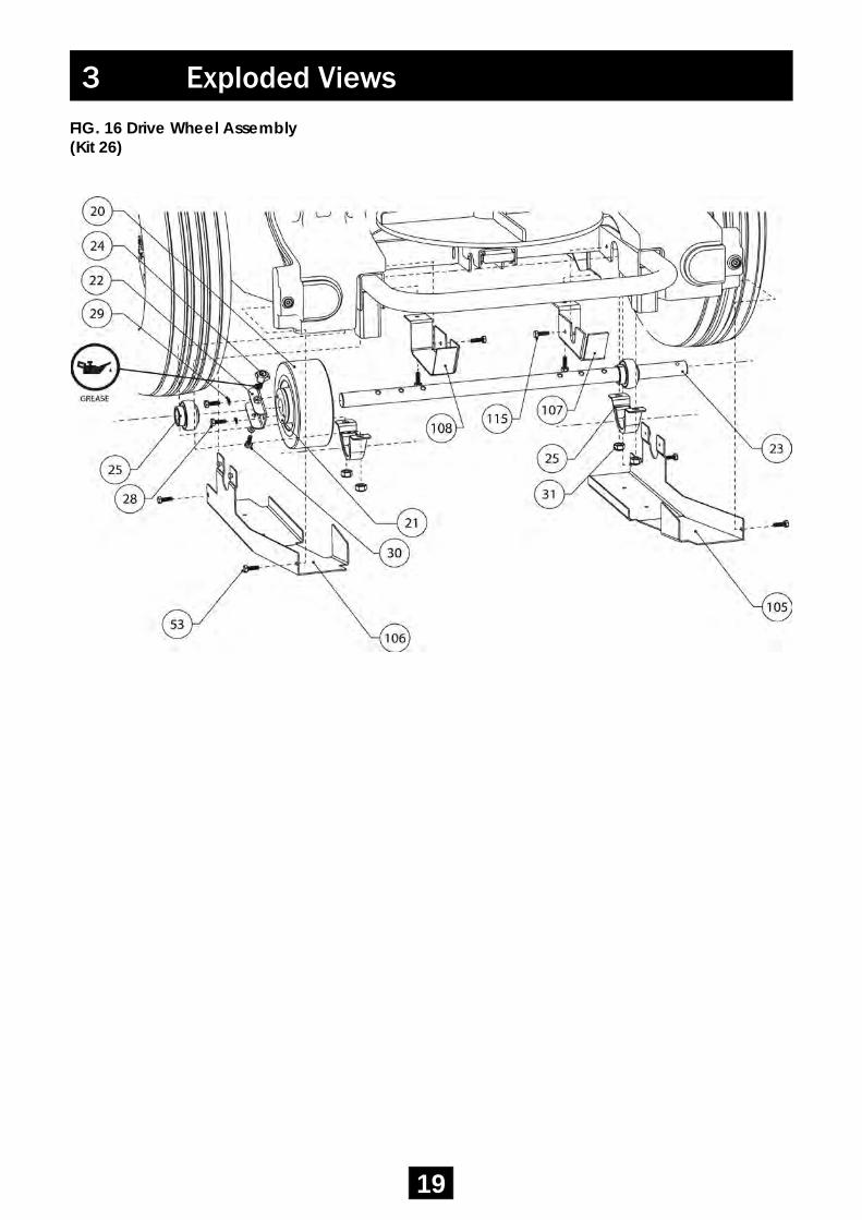
FIG. 16 Drive Wheel Assembly(Kit 26)
3 Exploded Views
19

4 Mechanics
20
FIG
. 17
Driv
e Sy
stem

4 Mechanics
21
FIG
. 18
Agi
tatio
n Sy
stem

4 Mechanics
22
FIG
. 19
Flow
Con
trol M
echa
nism

• A planned maintenance schedule of regular inspection is recommended, replacing components as necessary.• Replacement components are available direct from Glasdon.• Glasdon cannot be held responsible for claims arising from incorrect installation, unauthorised modification or misuse of the product.
Should you require any further assistance please contact us ontel: 01253 600410, fax: 01253 792558 or email: [email protected]
In accordance with our policy of continuous development and improvement, wereserve the right to make changes in design and specification without notice.Glasdon UK Limited products are manufactured under license worldwide andvarious components of the models are patented and design registered.
Issue 1 - October 2014 Stock no. C000/1027 © Copyright 06.10.2014 DWG No. 14B-032-85
The Turbocast 800 is CE Marked, it has been designed to comply with the relevant Standards and Directives for its product classification.
An EC Declaration of Conformity certificate and a copy of the CE Marking Turbocast 800 Technical File is available from the Glasdon UK Quality Assurance Department upon request.