sparrow: a magnetic climbing robot for autonomous
TRANSCRIPT

Journal of
Marine Science and Engineering
Article
Sparrow: A Magnetic Climbing Robot forAutonomous Thickness Measurement in ShipHull Maintenance
Raihan Enjikalayil Abdulkader * , Prabakaran Veerajagadheswar *, Nay Htet Lin,Selva Kumaran, Suresh Raj Vishaal and Rajesh Elara Mohan
ROAR Lab, Engineering Product Development, Singapore University of Technology and Design,Singapore 487372, Singapore; [email protected] (N.H.L.); [email protected] (S.K.);[email protected] (S.R.V.); [email protected] (R.E.M.)* Correspondence: [email protected] (R.E.A.); [email protected] (P.V.)
Received: 7 May 2020; Accepted: 11 June 2020; Published: 24 June 2020�����������������
Abstract: The maintenance of ship hulls involves a series of routine tasks during dry-docking thatrenews its life-time and operating efficiency. One such task is hull inspection, which is alwaysseen as harmful for human operators and a time-consuming task. The shipping maintenanceindustries started using the robotic solutions in order to reduce the human risk. However, mostof such robotic systems cannot operate fully autonomously due to the fact that it requires humansin the loop. On the other hand, an autonomous hull inspection robot, called Sparrow, is presentedin this paper. The proposed robot is capable of navigating autonomously on the vertical metalsurface and it could perform metal thickness inspection. This article summarizes the robot’smechanical design, system control, autonomy, and the inspection module. We evaluated the robot’sperformance by conducting experimental trials on three different metal plates that varied in thickness.The results indicate that the presented robot achieves significantly better locomotion while climbing,and it can autonomously measure the metal thickness, which significantly reduces the human effortsin real-time.
Keywords: ship maintenance; hull inspection; thickness measurement; vertical climbing robot
1. Introduction
The shipping industry is one of the oldest industries that acts as a backbone of global trade andeconomy. Today, over 53,000 merchant ships conduct international trade with an economic value of1.3 trillion USD, which includes general cargo, oil tankers, chemical tankers, passengers, and liquefiednatural gas [1]. All such ships must undergo a series of routine repair tasks while docking in a shipyardin order to maintain a smooth and foul free operation. Most of the major repairing tasks will beconducted during the dry-dock period, such as paint-stripping, inspection, painting, etc. Among those,inspection tasks are always seen as highly labor intense, and hazardous to human operators whenaccessing constrained narrow spaces. Ship owners diverted their interest in using robotic solutionsin order to reduce the amount of risk and drawbacks in the manual inspection process, which eventuallyopened a new market for robotics products. After witnessing the market demand, various aspects ofship hull inspection robots, including mechanism design, human interaction, and autonomy, have beenresearched in depth over the last two decades.
So far there have been numerous proposed mechanisms that target inspection tasks with smoothand robust vertical locomotion. One such robot can be seen in [2], where the robot is composed ofa rigid PVC body and four equal standard units, each including a combination of locomotion and
J. Mar. Sci. Eng. 2020, 8, 469; doi:10.3390/jmse8060469 www.mdpi.com/journal/jmse

J. Mar. Sci. Eng. 2020, 8, 469 2 of 18
adhesion systems. Each unit has a pair of wheels, rubber and magnetic to locomote and an actuatedstructure with a permanent magnet and two inductive sensors (one for detecting the high positionand one for the low position) for making adhesion adjustment to the vertical surface. In addition,each standard unit of the two rear systems has an auto-levelling structure which includes a mechanismwith a sliding guide and compensated through a spring for the event of irregulated and curvedsurfaces. In [3], the robot is made up of a body frame with two DC servo motors: one motor for drivingthe robot forward and backward and the other motor for the purpose of steering and a differential gearbox. The two smaller wheels are coupled with the steering DC motor at the front and the two largerwheels are assembled with the driving DC motor at the back. At the base of the robot body frame,twelve quantities of 30 × 30 × 5 permanent rare earth magnets are glued to support a clamping forceof 110 N to the operating surface with the air gap of 6 mm between the robot frame and the surface.In another robot [4], it consists of the body frame with the mechanisms of permanent magneticadhesion, tracked locomotion, and driving. Each track contains a roller chain in which 66 permanentmagnetic units are arranged. The robot uses a small and lightweight AC servo motor as its powerproducer. A tank is designed on the rear support bracket for the sprocket adjustment and in order toclimb over the uneven surface, an inclination angle of 45 degree is made between the driving sprocketand tensioning sprocket. In [5], the robot is implemented with differential drive locomotion mechanismwhile using two wheels that were equipped with 50 neodymium magnets each and the wheels aredriven by two DC gear motors. Every pair of the magnets are made to be in opposite magnetic fieldorientation in order to achieve iincreased adhesive power. The robot also has an elastic tail on whicha third neodymium permanent magnet is attached in order to maintain the stability of the roboton the wall.
In every robot, a reliable human robot interaction is required to achieve the stable robot function.Different human robot interactions can be found in the existing literature that are related to the hullinspection. In [6], analogue to digital AVR microcontroller based embedded system is used to operatethe motors and sensors and obtain the serial transmission of the analogue data for making dataanalysis. The onboard control module can be accessed with Bluetooth wireless communication system.For the robot in [7], the control system consists of two main units, console and mobile platform.The mobile platform is equipped with Arduino Mega 2560 microcontroller board to drive the motorsand transmitter-receiver modules and Raspberry Pi3-Model B single board computer to connect withcamera for video stream. For the purpose of interacting with humans, the console is equipped withjoysticks, analog potentiometer, and switches to control the input parameter and an iPad is usedas a display. In the oil tank inspection robot [8], the control system includes the embedded computersystem, the vision system, the motor driver system, the communication system and the sensing system,and even web based teleoperation for wireless robot commanding can be provided. In the controlsystem of [9], the Atmel ATmega328p microcontroller is used to interface with motors and sensors,an Android phone is utilized to control the robot through the Bluetooth wireless communication andLCD screen is used to get the inspection data from the wireless camera mounted on the robot.
Regarding autonomy, there is no such autonomous hull inspection robots with vertical wallclimbing mechanisms for the drydocking purpose in the shipyards. On the other hand, there are manyresearches regarding Automatic Underwater Vehicles (AUVs) for the underwater inspection worksduring the ship operations or wet docking. In one of AUVs [10], it describes the implementationof a simultaneous localization and mapping (SLAM) by using forward-looking sonar, FLS data.The algorithm named ESEIF is applied to accomplish the SLAM based upon features manually selectedwith FLS images. The results could demonstrate the capabilities of efficient mapping an underwatership hull, but it is not real time SLAM and cannot cover the whole coverage. In [11], the robot hasuniqueness due to using omnidirectional wheels while making capturing and mapping. Even thoughthe robot could make the autonomous inspection on underwater hull, the cost of implementing it is somuch expensive. In another research work [12], it reports real time SLAM based localization systemfor underwater ship hull inspection purpose. The first-generation extended Kalman filter (EKF) SLAM

J. Mar. Sci. Eng. 2020, 8, 469 3 of 18
system is developed using stereo camera and then landmarked tracking techniques are employed.Nevertheless, the observable ship hull size is limited according to the computational complexity ofthe EKF and the system needs more development in order to be a promising instrument.
By evaluating the existing literatures of ship hull inspection robot, it is proven that there is a hugegap in developing autonomous systems for dry docking conditions. Furthermore, most existing robotscannot achieve non-destructive testing that means evaluating the properties of a material withoutdamaging the part, in this case, for measuring the thickness of steel plates autonomously. To thisend, we are proposing a novel robot, named Sparrow, in this paper, which is capable of navigatingautonomously on the vertical metal surface and could perform metal thickness inspection. The majorcontribution in the proposed robotic system is the development of autonomous navigation along withthe ultrasonic thickness measurement system and its relevant mechanical design. Such an ability hasnever been demonstrated in the existing magnetic climbing robot for an inspection task. The majorchallenges that were encountered during the development of our Sparrow robot were its magneticadhesion mechanism, the integration of inspection modules, autonomous operation, and translatingthe theoretical design into a physical system. This paper summarizes all of these aspects and concludeswith experimental results that validate the autonomous inspection capability on three different metalplate varying with thickness. The proposed Sparrow robot represents an initial design towards the fullyautonomous climbing robot that can perform multi inspection task on a ship hull during dry docking.
The rest of the paper is organized, as follows. The mechanical design of the robot will bedescribed in Sections 2 and 3 will discuss about robot platform description. In Section 4, controldesign and autonomous feature will be shown and Section 5 will describe the experiments andresults. The discussion will be presented in Section 6 and, finally, conclusion and future work will berepresented in Section 7.
2. Mechanical Design
The mechanical structure of the proposed climbing robot is shown in Figure 1. It has thedimensions of 400 mm × 300 mm × 100 mm with the weight of 14 kg. As the robot is specialized ininspection, it consists of permanent magnetic adhesion mechanism, locomotion mechanism, the frameof the body, and the inspection system that is capable of carrying out metal thickness inspection task.In the adhesion of this kind of applications, even though there are different principles, pneumaticand magnetic are the most suitable ones and magnetic adhesion is more reliable because of no powerrequirement. Such pneumatic robots can be seen in [13,14]. The other adhesion techniques, such asmechanical, electrostatic, and chemical are applied in some robots, like [15–18], but not suitable forthe application that we are considering. To achieve an efficient climbing robot, it is critical to runthe force analysis before we decide the amount of magnets placed on the robot that enables sufficientadhesion, which is discussed in the next session.
Figure 1. Mechanical Structure. 1. Lidar, 2. Magnetic Wheel, 3. Emergency Stop, 4. Thickness Probe,5. Motor Control, 6. Thickness Gauge,7. IMU 8. Dc Motor, 9. Jetson Nano, 10. Microcontroller,11. Bluetooth, 12. Camera.

J. Mar. Sci. Eng. 2020, 8, 469 4 of 18
Force Analysis
It is of importance that the Sparrow adheres to the ship surface all the way and does not encounterslippage of any form, in order to execute its inspections properly. Thus, all four wheels must bein contact with the target area of the ship hull and possess the required adhesion forces to do so duringany operation. The forces must be sufficient to prevent the pivoting of the robot on any particularwheel, which can rotate it away from the wall. Hence, the magnetic adhesion forces exhibited by eachwheel has to be increased by tailoring the number of magnetic beads that are placed inside the wheels,if it is required. A force analysis model then becomes necessary to gauge the net adhesion forces ofthe wheels, which can enable us to deduce whether more magnetic beads are needed per wheel thanthe current amount placed within.
When the robot is at rest on a surface in the vertical position, it experiences gravity, the magneticadhesion forces from its wheels, the normal contact forces from the surface, and friction that arisesin between these, the wheels, and the surface. The force analysis is done on the robot shown tofunction at an inclined angle facing upwards, which would be a more realistic scenario on a shiphull. The studies conducted to account for various scenarios let to the derivation of a general studytechnique for the static forces present at equilibrium conditions. Figure 2 depicts a robot operationmodel, comprising of a typical setup as well as its representation in a robot coordinate frame.
Our objective is to ensure that the Sparrow is capable of attaching itself to a surface in any arbitraryangle. In Figure 2, F1,2, and F2,2 are the combined, magnetic adhesive forces of the front wheels andback wheels, respectively. Each wheel itself is fitted with a layer of magnetic strips to produce a netadhesion force on each wheel towards the ship surface. F1,1 and F2,1 are the resulting sliding frictionforces while W is gravity coupled together with the mass of the robot. B is the distance betweenthe point of contact of the wheel on the surface, to the Centre of Gravity (CG) of the robot. The distanceT represents the length between the respective front/back wheel centres to the CG of the robot. θ isthe angle of inclination with regard to the slipping surface. Point U is the likely pivot around whichthe robot is expected to rotate by if the top wheels are designed to exert more adhesive force.
We aim to solve for F1,2, F2,2 and, thus, made the following derivations from the Force Diagramas well as our physical calculations. W = (14 kg)(9.81 m/s2) = 137.34 N, while 2T = 400 mm andB = 110 mm. The sum of forces in the Y-Reference Frame, encompassing the frictional forces andthe relevant force from W, are:
∑ FY R −→ F1,1 + F2,1 = (W)(cos θ) (1)
The sum of forces in X-Reference Frame, including the target adhesion forces and the relevantforce from W, are:
∑ FX R −→ F1,2 + F2,2 = (W)(sin θ) (2)
Taking moments around Point U, we obtain:
∑ MU −→ (2T)(F2,2) = (W)[(T)(sin θ)− (B)(cos θ)] (3)
Rewriting Equation (2), we get:
F1,2 = (W)(sin θ)− F2,2 (4)
Manipulating Equation (3), we have:
F2,2 = (W2T
)[(T)(sin θ)− (B)(cos θ)] (5)

J. Mar. Sci. Eng. 2020, 8, 469 5 of 18
Substituting Equation (5) into Equation (4), we obtain:
F1,2 = (W)(sin θ)− (W2T
)[(T)(sin θ)− (B)(cos θ)]
F1,2 = (W2T
)[(T)(sin θ) + (B)(cos θ)] (6)
Figure 2. (i) Typical setup of Robot and (ii) Static Force Analysis in Robot Frame.
The forces of friction are such that F1,1 = (µ)(F1,2) and F2,1 = (µ)(F2,2), where µ is the coefficientof friction between the wheel and ship surface. Thus, Equation (1) can be rewritten as:
µ(F1,2) + µ(F2,2) = (W)(cos θ)
F1,2 + F2,2 =(W)(cos θ)
µ(7)
However, Equation (7) is identical to Equation (2) and, thus, represents an over-constrainedphenomena. Equating both equations together yields:
θ = tan−1(1µ)
Taking an arbitrary value of µ = 1, θ = 45◦, which implies that Equation (2) satisfies all otherequations at this angle only. However, our main focus is Equations (5) and (6). Using an angle of 20◦
in Equations (5) and (6), we derive:
F1,2 = 58.97N and F2,2 = −12.00N

J. Mar. Sci. Eng. 2020, 8, 469 6 of 18
The above values fulfill the following condition needed to prevent the rotation of the robot,which is: F1,2 > F2,2.
However, it has to be noted that the overall weight of the robot is at 137.43 N and in order toensure that the forces from the wheels match up to this weight, more magnetic beads might be requiredat the front wheels of the robot as well as the back wheels. We designed the magnetic beads accordingto our analysis in order to maintain the foul free locomotion on the metal surface.
In Sparrow, we used 30 magnets with each magnetic belt to supply the net adhesion force.The wheels have their own motors, hence a total of four motors is used for the four wheels.Each wheel mounted with the motor through a fabricated coupler which provides rigidity forthe wheel while locomotion. All other electronic components are fixed on the main chassis of the robot.Each components are mounted with enough gaps to make sure there is no conflict of signal interferencethat creates sensor error.
Figure 3. Sparrow robot placed on a metal plate.
3. Robotic Platform Description
The presented inspection robot’s internal components are separated as functional units. Each ofthe functional units are explained in this section. Figure 3 shows the robot on a metal surfaceat the facility while conducting the experiments. An overview of the proposed architecture is depictedin Figure 4. It consists of Sparrow bot with thickness gauge, the app with control and video feed,storage for logging the thickness data, and the communication medium. The HMI App screen-layoutis split in to two parts, the upper part is for the video feed from the camera, whereas the lower regionis for the locomotion control buttons and autonomous button. We used Poly-lactic Acid (PLA) to makethe body cover of the robot, 5 mm thick aluminum sheet is used as the base of the robot. Figure 5depicts the hardware architecture of the Sparrow robot. It comprises of six functional units, includingJetson Nano as Central Computing Unit, sensor unit comprising of VectorNav IMU, Wireless 1080 pCamera and Marvel mind Beacons, Thickness measuring unit, Locomotive Unit (Arduino Mega 2560and motors), and communication unit comprising of Bluetooth adapter. Tethered power is optedin the proposed scheme, this makes the operational time of the robot higher. Nevertheless, when usingbattery, the operational time is very limited and adds weight to the robot.

J. Mar. Sci. Eng. 2020, 8, 469 7 of 18
Figure 4. Overview of the proposed system.
Figure 5. Hardware Architecture of sparrow robot.
3.1. Main Computing Unit
The Main Computing Unit comprises of Jetson Nano, a low voltage System on Chip (SoC) singleboard computer with 4 core ARM A57 CPU and four gigabytes of RAM. Rosserial package is usedto interface Locomotive Unit with Main Computing unit. MCU acts as Robot Operating System(ROS) [19] master and Arduino as a slave to locomote to the goal points.
3.2. Locomotive System
Arduino is used as the Locomotive Control Unit. Roboclaw motor driver 2 × 30A are used todrive the motor. Arduino uses serial communication to communicate with Roboclaw. 18VDC Cytronmotor with a high torque of 255 kgcm is used to drive the platform with 94 RPM. The speed anddirection for each motor is given from the motor driver. Fundamental movements, like Forward,Reverse, and pivoting, are utilized for locomotion of the robot. Robot’s maximum speed is 0.6 m/s.
3.3. IMU
VectorNav VN-100 is a superior Inertial Measurement Unit that incorporates the most recentMEMS sensor innovation. VN-100 consolidates three-axis accelerometers, three-axis gyros, three-axis

J. Mar. Sci. Eng. 2020, 8, 469 8 of 18
magnetometers, along with a 32-bit processor. Yaw angle from the IMU is utilized as the direction ofthe robot. Serial communication protocol is utilized to obtain the data from IMU.
3.4. Marvel Mind Beacon
Marvel mind Indoor Navigation System with a precision of 2 cm is employed to obtain the locationof the robot on the ship hull. Stationary Ultrasonic beacons are interconnected via radio interface toform the reference points, and a mobile beacon is attached to the body of the robot that can be tracked.The real-time location data are taken from the mobile beacon and are given to the ROS master node.Four beacons are set at each corner of the metal plate, can be set at license-free band (433 MHz or915/868 MHz), size of each beacon is approximately 55 × 55 × 65 mm. Mobile beacons location iscalculated by sending ultrasonic signal to the stationary beacons and finding the propagation delaywhile using trilateration. The map is configured and loaded to the modem. Once the map is loaded,the mobile beacon’s position can be tracked. Marvel-mind provides ROS package for the beacons, withwhich it is easy to get the data of both stationary and mobile beacon. Calibration is easy with marvelmind beacons, once all of the beacons are switched ON and modem with map is powered. Mobilebeacon starts giving the coordinates that are accessed using the ROS package.
3.5. Vision System
The vision framework comprises of a Wi-Fi HD 1080 p camera. Camera placement is done 65 mmabove the surface with a tilt of 40 degrees; this is to ensure that the operator is able to see clearlythe condition of the hull in-front of the robot shown in Figure 6. With the real-time feedback fromthe camera, robot can be controlled precisely. The camera operates at 5 V, with a power rating of threewatts. Camera has frame rate of 25 fps at 1080 p, is around 10 g in weight.
Figure 6. Camera and probe placement.

J. Mar. Sci. Eng. 2020, 8, 469 9 of 18
3.6. Thickness Measurement Gauge
38DL PLUS Ultrasonic Thickness Gauge from Olympus is used for thickness measurement,range of thickness, which can be measured as 0.08 mm to 635 mm. The gauge is attached to the centrepart of the robot using a proper housing, as shown in Figure 6. This gauge is controlled using a linearsolenoid, which, when actuated, makes the gauge to touch the ground and obtain the thicknessreading. This solenoid is controlled using a relay and activated using the Arduino micro-controller.The thickness data are logged on with the current position of the robot, i.e., the data from the beaconsare taken at the time of logging the thickness measured. In order to protect the probe from damage,the probe is disengaged from the metal surface at the time of pivoting.
4. Control Design and Autonomous Feature
Nowadays, autonomous ship hull inspection robots with the wall climbing mechanisms are stillresearching, even though some semi-autonomous and autonomous visual inspection robot using AerialVehicles, such as [20–24], and very few autonomous maintenance robots of ship hull, such as [25–27]can be seen. In this section, the general control architecture and autonomous feature of the robot ispresented. This section covers the localisation technique, path planning, and the control flow-chart forautonomous thickness measurement.
4.1. General Control Architecture
The designed system works under Robot Operating System architecture that communicatesto each physical module to collect senor data and acts as an interface for motor drivers that canexecute the locomotion. We constructed our control architectures as a set of state machines, as shownas a flow chart in Figure 7. These states can be activated through sending commands to the robotthrough the Bluetooth enabled App. According to the command, the following states will be executed,which includes manual state and autonomous state.
Figure 7. State Machine flow-chart.

J. Mar. Sci. Eng. 2020, 8, 469 10 of 18
4.2. Manual Mode
In the manual mode, the user controls the platform remotely using the direction control buttonson the mobile app. The Bluetooth receiver is appended on the Main Computing Unit (Jetson-Nano),which obtains the information signals (ROS master) and converts them as commands for Arduino(ROS Slave). These information signals at that point are passed onto the speed controller to createcommand velocity for the robot wheels. For the most part, the manual control is utilized at the pointof deployment, so as to position the robot on the ship hull properly. When the human administratorclarifies that the robot is in a right position to perform autonomous thickness inspection, at that pointhe will press the dedicated button on the controller application to actuate the autonomous mode.
4.3. Autonomous Feature
Obtaining the accurate position of the robot on the ship’s hull is of highest priority forthe autonomous operation of the robot. Ultrasonic based beacon systems were used to obtain the preciselocation of the robot on the hull. Fixed beacons that are interlinked via radio-waves, form a networkso that mobile beacon inside the network can be tracked and localized with precision, providedthat it should maintain line-of-sight condition. The distance between mobile beacons and all ofthe static beacons are computed using ultrasonic waves, from this, the position of the mobile beacon isdetermined. Robot’s coordinate is obtained by attaching a mobile beacon on the robot. High precisionIMU from vectornav is interfaced with the Main Computing Unit to obtain the orientation data./odom_beacon topic is published by converting the beacon data into ROS-based sensor messages.The encoder data and IMU data are fused together while using the extended kalman filter tool topublish a secondary odometry in ROS sensor message format under the topic name/odom_encoder.This is done so that we can reduce the error from the beacons due to noises and external disturbances.Global and local path generators are fed with the filtered odometry [28,29].
A global path is generated by the system when the user presses the dedicated button for autonomyon the Control App. The user can assign specific length and breadth for the global path to be generatedfor a specific area. The thickness inspection task can be performed in a zigzag pattern [30–32] tocover the specified area. Velocity commands for the wheels are generated by the local planner,which subscribes to the global planner. The thickness measuring task is done in a way such that,once the operator presses the autonomous button, the thickness measuring gauge is pushed downon to the hull surface and dragged as the robot moves in the zigzag pattern to cover the area that isspecified by the user, the thickness data, along with the position of the robot is displayed on the ControlApp and also stored on the database. Once the inspection completed for the given boundary, the robotwill go back to the manual mode.
5. Experiments and Results
At the time of thickness inspection, the robot might fail to complete the tasks due to position errorsand slippages. Such degradation in performance could occur due to the various causes that includespeed of the robot’s locomotion or the surface issues or even due to error in operational parameters.A series of exploratory tests were led in the research facility in order to validate and verify the robotparameters. The tests incorporate slippage test and thickness measurement test.
5.1. Slippage Test
Slippage causes error in robot position, which would also lead to an error in thicknessmeasurement. The more the slippage, the more the error. Accordingly, slippage is the primarycandidate that needs to be considered in optimising the performance of the robot. For that,the following experiments are done.

J. Mar. Sci. Eng. 2020, 8, 469 11 of 18
1. Robot is tested on a metal plate having a dimension of 5 m in length and 2 m in height insidethe research facility. The metal plate is inclined about 80◦ to the wall, where the robot is subjectedto move in horizontal and vertical path for a fixed time.
2. Maximum speed of the robot is 0.6 m/s. Four sets of speeds are being used for testing, say 20%,50%, 80% and 100% (0.18, 0.3, 0.48, and 0.48 m/s).
3. The slippage for each speed is found out by comparing the wheel encoder values with the datafrom the beacons in terms of positional coordinates (x, y). Slippage or error is the differencein the distance covered or the path generated from the wheel encoder and the beacons.
Slippage Test Results
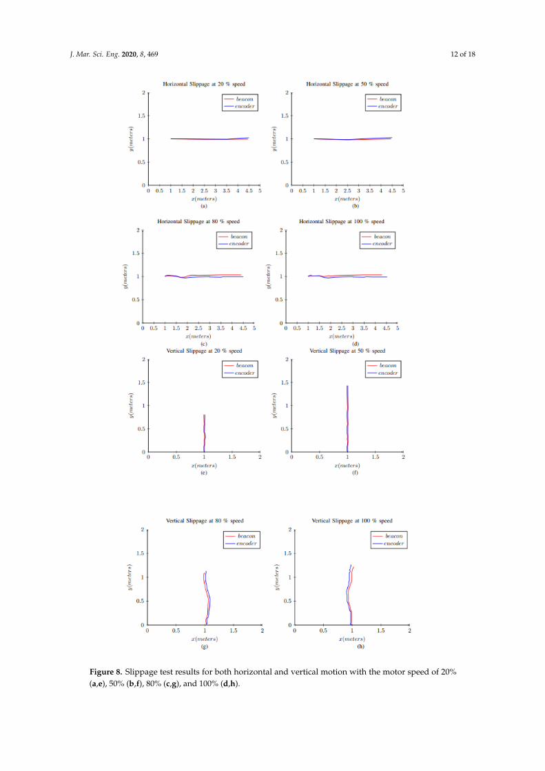
Horizontal slippage and vertical slippage of the robot with different speeds were assessed.For the horizontal slippage test, the robot is set to 20% of its maximum speed and it is placedon the centre of the sheet. Subsequently, the robot is moved forward for 4 m approx and the encoderand beacon readings are taken for the particular time interval. The same steps are repeated fordifferent speeds. Figure 8a shows the position of the robot on the sheet obtained from encoderand beacon readings. It can be seen that, the plot is a straight line, and there is even no differencebetween the positional data from the beacons and the encoders. Figure 8b shows the position ofthe robot on the sheet obtained from encoder and beacon readings at 50% of the speed. It can benoted that the plotted graph is almost a straight line, and no noticeable difference can be observedfrom the positional data from encoder and beacon. The horizontal slippage is minimal at 50% speed.In Figure 8c, the data obtained are plotted when robot is moved at 80% of the speed. It can be observedthat the robot is deviating from going in a straight line, and there is a difference in the positional datafrom encoder and beacon. This confirms that there is considerable slippage when robot is operated at80% of its speed than the previous case. From Figure 8d, it can be deduced that the horizontal slippageis maximal when it is operated at 100% speed.
For the vertical slippage test, the robot is set to 20% of its maximum speed and placedon the bottom of the sheet. Subsequently, the robot is moved forward for fixed time, the encoder andbeacon readings are observed for the particular time interval. Figure 8e,f show the robot position whenoperated at 20% speed and 50% speed. It can be seen that the robot is stable and moves without anynoticeable slip. A significant amount of slippage can be observed when the robot is operated at 80%and 100% speeds, as can be observed in Figure 8g,h.
The test results are shown in Figure 8 and the average positional error between the encoder andbeacon values at different speeds is depicted in Table 1. This table is deduced by testing the roboton the steel plate at various speeds five consecutive times. From the results, it can be concluded that,with an increase in speed, the slippage increases. However it can also be observed that, at 20% and50%, the slippage or error is minimal, for best performance, is beneficial to take the highest speed withless error; hence, it is optimal to take 50% as the operating speed. Furthermore, we chose positionalcoordinates of real-time encoder and beacon values to exhibit the real-time slippage of the robot whilemoving horizontally and vertically on the plate instead of error between beacon and encoder values.This arrangement is due to, in some cases, the error gap between beacon and wheel encoder being verylow to plot. For example, in 20% and 50% speed, the error is very minimal and cannot be visualisedon the plot. There is a limitation for doing the experiment inside our facility; longer runs will beperformed and analysed in the future work.
Table 1. Average positional error between encoder and beacon values at different speeds.
SlNo Speed in Percentage (%) Error in Meters (m)
1 20 0.032 50 0.0323 80 0.0484 100 0.052
J. Mar. Sci. Eng. 2020, 8, 469 12 of 18
Figure 8. Slippage test results for both horizontal and vertical motion with the motor speed of 20%(a,e), 50% (b,f), 80% (c,g), and 100% (d,h).

J. Mar. Sci. Eng. 2020, 8, 469 13 of 18
5.2. Autonomous Thickness Measurement Test
We evaluated the performance of the proposed robot in terms of its thickness measurementability using two sets of experiments in three different scenarios. The experimental scenarios werevaried by changing the thickness of the plate. In our experiments, we used metal plate with thicknessof 5 mm, 8 mm, and 10 mm. The considered metal plates have a dimension of 2 m in length and1.5 m in height. In the first set of experiments for all considered metal plates, the robot is allowed toperform the thickness measurement task at the centre of the plate for an area of 0.7 m × 0.7 m. In thesecond set of experiments, we modified the plates by welding a 5 mm thick metal piece at the back ofthe test bed with 200 mm in length and 20 mm in width. In both experiments, the robot is operatedin the following sequence
1. manually controlling the robot to move to the starting point;2. autonomously covering the 0.7 m × 0.7 m area in zigzag path with enabled thickness
measurement data logging; and,3. returning back to the manual mode after completing the coverage.
During the autonomous operation, the robot moves in a horizontal direction for 0.7 m bycontinuously measuring the thickness values. Similarly, the robot performs continuous thicknessmeasurement during the vertical climbing. The robot climbs in the vertical direction for 0.1 m.While performing, the pivot turns, the robot disengages the measuring system and breaks the probecontact with the surface in order to protect the probe. In both vertical and horizontal motion,the measured values are stored on the data logger continuously along with the robot’s pose. The loggedvalues are post processed in order to visualise the thickness evenness on the considered plates.
Simple MATLAB program is created to visualise the logged thickness value. The algorithmwould plot the logged information on a two-dimensional (2D) graph. Each thickness value is plottedas a colored circle with respect to the position of the robot. Three colours red, green, and blue areused to represent the measured thickness values. The algorithm chooses the appropriate colour forthe circle to plot the particular thickness value. For instance, if the single measured value is lower thanthe actual thickness of the plate, then the algorithm would choose blue, for a higher value it choosesred, and green for actual. After the plot is generated, the analysis will be done for further stepsin the inspection. The algorithm will compute the percentage of green points at the end of each trialfrom the number of green points logged from the total recorded points.
Thickness Measurement Results
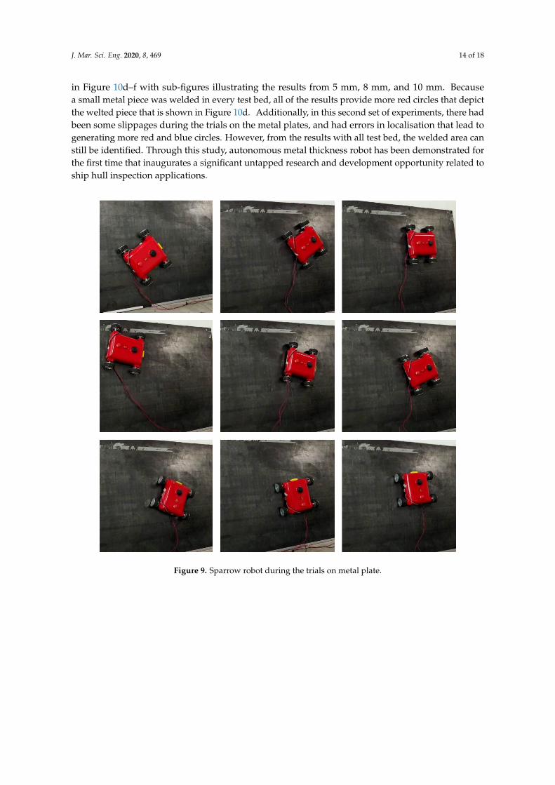
The thickness measurement trials were started by placing the metal plate vertically and attachingthe robot on the same. Initially, the robot was manually controlled to move the robot to the centreand the autonomous mode was selected. The robot continued the zigzag motion by measuringthe thickness of the plate. Figure 9 shows some robot screen shots while performing the thickness trials.Once the coverage is completed the robot is retrieved to visualise the logged data by post processing it.Figure 10a–c show the plots generated form the visualisation program for the experiments conductedon the 5 mm, 8 mm and 10 mm plates. All generated plots have more than 96% green circles thatshow the proposed robot could successfully measure the thickness value with considered scenarios.There are some places we can witness the red circle and blue circles in the results generated fromall the experiment conducted. This is due to the less thickness, there are few slippages that triggerthe robot to align its orientation and path which affect the probes contact on the plate leads to errorreading. Also the error of localisation is causing the points to deviate and scatter. In some placeswe noticed that the false reading happened because of plate surface unevenness.
In the second set of experiments, the metal piece was welded at the backside of the test bed.Afterwards, similar procedures were run to conduct the experiments and generated the plot byretrieving the robot at the end of each trial. Here, the percentage of green circles generated is reducedto 93% because of the welded metal piece. The provoked plot for the conducted experiments is shown
J. Mar. Sci. Eng. 2020, 8, 469 14 of 18
in Figure 10d–f with sub-figures illustrating the results from 5 mm, 8 mm, and 10 mm. Becausea small metal piece was welded in every test bed, all of the results provide more red circles that depictthe welted piece that is shown in Figure 10d. Additionally, in this second set of experiments, there hadbeen some slippages during the trials on the metal plates, and had errors in localisation that lead togenerating more red and blue circles. However, from the results with all test bed, the welded area canstill be identified. Through this study, autonomous metal thickness robot has been demonstrated forthe first time that inaugurates a significant untapped research and development opportunity related toship hull inspection applications.
Figure 9. Sparrow robot during the trials on metal plate.

J. Mar. Sci. Eng. 2020, 8, 469 15 of 18
Figure 10. Thickness measurement test conducted on non welded and welded pates of different thickness.(a) Thickness test on 5 mm plate; (b) Thickness test on 8 mm plate; (c) Thickness test on 10 mm plate;(d) Thickness test on welded 5 mm plate; (e) Thickness test on welded 8 mm plate; (f) Thickness test onwelded 10 mm plate.
6. Discussion
The sensor data are stored in the log file with the positional coordinates, so that the user canobtain the correct thickness data with respect to each point. Furthermore, we assigned the coloursas a preliminary measure for the users to visualise, and get an idea on whether there is any differencein the thickness throughout the area on the hull plate that was inspected. Once the change in thicknessis found, the user can check on the real thickness value in the logged data. The presented approach isscalable to 30 m × 30 m with the current setup, because that is the recommended distance betweenthe stationary beacons. However, because the initial setup time for the beacons is very small, we canmove the beacons to the next 30 m2 area to start inspecting that region. Continuing on beacon systems,

J. Mar. Sci. Eng. 2020, 8, 469 16 of 18
there are few places where we detected ultra sonic echos reflecting from the metal surface, causinglocalisation errors. Thus, localisation algorithm should be improved by fusing additional sensorinformation, such as camera and three-dimensional (3D) lidar.
7. Conclusions
In this paper a novel autonomous metal thickness inspection robot, called Sparrow, is presentedfor the ship hull maintenance task. The mechanical design, force analysis and autonomous inspectionfeature are presented, and the performance of the autonomous navigation of the robot is successfullyvalidated on a metal surface. The experiments were performed to validate the locomotion efficiencywith the slippage test, and autonomous metal thickness measurement performance under variousscenarios. Specifically with autonomous thickness measurement task, two set of experiments areconducted on three different metal plates with thickness of 5 mm, 8 mm, and 10 mm. In all ofthe experiments, the proposed robot exhibits significant performance advantage in terms of slippagefree locomotion. Furthermore, with thickness measurement, the logged thickness value is postprocessed at the end of every trial to generate a 2D plot to visualise the thickness evenness of the plate.The results show that the proposed robot could successfully measure the metal plate’s thicknessevenness in all considered scenarios. There are few rooms where we can focus on improvementsin the existing design, which are listed below:
1. Improving the design to navigate on the curved surface;2. To study the application of machine learning in classifying the metal surface’s corrosion level; and,3. Optimising the path generation of the robot to perform selective measuring of thickness.
Author Contributions: Conceptualization, R.E.A. and P.V.; Data curation, N.H.L. and S.K.; Formal analysis,R.E.A. and S.R.V.; Project administration, R.E.M.; Validation, R.E.M.; Writing—original draft, R.E.A. and P.V.;Writing—review & editing, N.H.L., S.K. and R.E.M. All authors have read and agreed to the published version ofthe manuscript.
Funding: This research is supported by the National Robotics Programme under its Robotics Enabling Capabilitiesand Technologies (Funding Agency Project No. 192 25 00051) and administered by the Agency for Science,Technology and Research.
Acknowledgments: The authors would like to thank, the National Robotics Programme, ROARS Lab, OceaniaRobotics, and SUTD for their support.
Conflicts of Interest: The authors declare that there is no conflict of interest.
References
1. Budholiya, A. Ship Repair and Maintenance Services Market is Expected to Reach Over US dollar 39,934.8Mn By the 2028 End. Available online: https://marketersmedia.com/ship-repair-and-maintenance-services-market-is-expected-to-reach-over-us-399348-mn-by-the-2028-end/462718 (accessed on 28 April 2020).
2. Oliveira, A.; Silva, M.; Barbosa, R. Architecture of an wheeled climbing robot with dynamic adjustment ofthe adhesion system. In Proceedings of the IEEE 8th International Symposium on intelligent Systems andInformatics, Subotica, Serbia, 10–11 September 2010; IEEE: Piscataway, NJ, USA, 2010; pp. 127–132.
3. Mondal, S.; Sattar, T.; Bridge, B. Tofd inspection of v-groove butt welds on the hull of a container ship witha magnetically adhering wall climbing robot. In Proceedings of the 5th International Conference on Climbingand Walking Robots and the Support Technologies for Mobile Machines, Paris, France, 25–27 September 2002;Professional Engineering Publishing Ltd.: London, UK, 2002; pp. 955–961.
4. Huang, H.; Li, D.; Xue, Z.; Chen, X.; Liu, S.; Leng, J.; Wei, Y. Design and performance analysis of a trackedwall-climbing robot for ship inspection in shipbuilding. Ocean. Eng. 2017, 131, 224–230. [CrossRef]
5. Eich, M.; Vögele, T. Design and control of a lightweight magnetic climbing robot for vessel inspection.In Proceedings of the 2011 19th Mediterranean Conference on Control & Automation (MED), Corfu, Greece,20–23 June 2011; IEEE: Piscataway, NJ, USA, 2011; pp. 1200–1205.

J. Mar. Sci. Eng. 2020, 8, 469 17 of 18
6. Howlader, M.O.F.; Sattar, T.P. Development of magnetic adhesion based climbing robot for non-destructivetesting. In Proceedings of the 2015 7th Computer Science and Electronic Engineering Conference (CEEC),Colchester, UK, 24–25 September 2015; IEEE: Piscataway, NJ, USA, 2015; pp. 105–110.
7. Stepson, W.; Amarasinghe, A.; Fernando, P.; Amarasinghe, Y. Design and development of a mobile crawlingrobot with novel halbach array based magnetic wheels. In Proceedings of the 2017 IEEE/RSJ InternationalConference on Intelligent Robots and Systems (IROS), Vancouver, BC, Canada, 24–28 September 2017; IEEE:Piscataway, NJ, USA, 2017; pp. 6561–6566.
8. Shen, W.; Gu, J.; Shen, Y. Proposed wall climbing robot with permanent magnetic tracks for inspecting oiltanks. In Proceedings of the IEEE International Conference Mechatronics and Automation, Niagara Falls,ON, Canada, 29 July–1 August 2005; IEEE: Piscataway, NJ, USA, 2005; Volume 4, pp. 2072–2077.
9. San-Millan, A. Design of a teleoperated wall climbing robot for oil tank inspection. In Proceedings of the 201523rd Mediterranean Conference on Control and Automation (MED), Torremolinos, Spain, 16–19 June 2015;IEEE: Piscataway, NJ, USA, 2015; pp. 255–261.
10. Walter, M.; Hover, F.; Leonard, J. SLAM for ship hull inspection using exactly sparse extended informationfilters. In Proceedings of the 2008 IEEE International Conference on Robotics and Automation, Pasadena,CA, USA, 19–23 May 2008; IEEE: Piscataway, NJ, USA, 2008; pp. 1463–1470.
11. Soberi, M.S.B.M.; Zakaria, M.Z.B. Autonomous ship hull inspection by omnidirectional path and view.In Proceedings of the 2016 IEEE/OES Autonomous Underwater Vehicles (AUV), Tokyo, Japan, 6–9 November2016; IEEE: Piscataway, NJ, USA, 2016; pp. 38–43.
12. Schattschneider, R.; Maurino, G.; Wang, W. Towards stereo vision slam based pose estimation for ship hullinspection. In Proceedings of the OCEANS’11 MTS/IEEE KONA, Waikoloa, HI, USA, 19–22 September 2011;IEEE: Piscataway, NJ, USA, 2011; pp. 1–8.
13. Wu, S.; Wu, L.; Liu, T. Design of a sliding wall climbing robot with a novel negative adsorption device.In Proceedings of the 2011 8th International Conference on Ubiquitous Robots and Ambient Intelligence(URAI), Incheon, Korea, 23–26 November 2011; IEEE: Piscataway, NJ, USA, 2011; pp. 97–100.
14. Lee, G.; Kim, H.; Seo, K.; Kim, J.; Kim, H.S. MultiTrack: A multi-linked track robot with suction adhesion forclimbing and transition. Robot. Auton. Syst. 2015, 72, 207–216. [CrossRef]
15. Liu, R.; Chen, R.; Shen, H.; Zhang, R. Wall climbing robot using electrostatic adhesion force generated byflexible interdigital electrodes. Int. J. Adv. Robot. Syst. 2013, 10, 36. [CrossRef]
16. Daltorio, K.A.; Horchler, A.D.; Gorb, S.; Ritzmann, R.E.; Quinn, R.D. A small wall-walking robot withcompliant, adhesive feet. In Proceedings of the 2005 IEEE/RSJ International Conference on Intelligent Robotsand Systems, Edmonton, AB, Canada, 2–6 August 2005; IEEE: Piscataway, NJ, USA, 2005; pp. 3648–3653.
17. Murphy, M.P.; Sitti, M. Waalbot: An agile small-scale wall-climbing robot utilizing dry elastomer adhesives.IEEE/ASME Trans. Mechatron. 2007, 12, 330–338. [CrossRef]
18. Osswald, M.; Iida, F. Design and control of a climbing robot based on hot melt adhesion. Robot. Auton. Syst.2013, 61, 616–625. [CrossRef]
19. Quigley, M.; Conley, K.; Gerkey, B.; Faust, J.; Foote, T.; Leibs, J.; Wheeler, R.; Ng, A.Y. ROS: An open-sourceRobot Operating System. In Proceedings of the ICRA Workshop on Open Source Software, Kobe, Japan,12–17 May 2009; Volume 3, p. 5.
20. Bonnin-Pascual, F.; Garcia-Fidalgo, E.; Ortiz, A. Semi-autonomous visual inspection of vessels assistedby an unmanned micro aerial vehicle. In Proceedings of the 2012 IEEE/RSJ International Conference onIntelligent Robots and Systems, Vilamoura, Portugal, 7–12 October 2012; IEEE: Piscataway, NJ, USA, 2012;pp. 3955–3961.
21. Bonnin-Pascual, F.; Ortiz, A.; Garcia-Fidalgo, E.; Company, J.P. A micro-aerial platform for vessel visualinspection based on supervised autonomy. In Proceedings of the 2015 IEEE/RSJ International Conference onIntelligent Robots and Systems (IROS), Hamburg, Germany, 28 September–2 October 2015; IEEE: Piscataway,NJ, USA, 2015; pp. 46–52.
22. Garcia-Fidalgo, E.; Ortiz, A.; Bonnin-Pascual, F.; Company, J.P. A mosaicing approach for vessel visualinspection using a micro-aerial vehicle. In Proceedings of the 2015 IEEE/RSJ International Conference onIntelligent Robots and Systems (IROS), Hamburg, Germany, 28 September–2 October 2015; IEEE: Piscataway,NJ, USA, 2015; pp. 104–110.
23. Ortiz, A.; Bonnin-Pascual, F.; Garcia-Fidalgo, E. Vessel inspection: A micro-aerial vehicle-based approach.J. Intell. Robot. Syst. 2014, 76, 151–167. [CrossRef]

J. Mar. Sci. Eng. 2020, 8, 469 18 of 18
24. Ortiz, A.; Bonnin-Pascual, F.; Garcia-Fidalgo, E.; Company-Corcoles, J.P. Vision-based corrosion detectionassisted by a micro-aerial vehicle in a vessel inspection application. Sensors 2016, 16, 2118. [CrossRef][PubMed]
25. Cho, C.S.; Kim, J.D.; Lee, S.G.; Lee, S.K.; Han, S.C.; Kim, B.S. A study on automated mobile painting robotwith permanent magnet wheels for outer plate of ship. In Proceedings of the IEEE ISR 2013, Seoul, Korea,24–26 October 2013; IEEE: Piscataway, NJ, USA, 2013; pp. 1–4.
26. Kermorgant, O. A magnetic climbing robot to perform autonomous welding in the shipbuilding industry.Robot. Comput.-Integr. Manuf. 2018, 53, 178–186. [CrossRef]
27. Ozog, P.; Eustice, R.M. Toward long-term, automated ship hull inspection with visual SLAM, explicit surfaceoptimization, and generic graph-sparsification. In Proceedings of the 2014 IEEE International Conferenceon Robotics and Automation (ICRA), Hong Kong, China, 31 May–7 June 2014; IEEE: Piscataway, NJ, USA,2014; pp. 3832–3839.
28. Veerajagadheswar, P.; Ping-Cheng, K.; Elara, M.R.; Le, A.V.; Iwase, M. Motion planner for a Tetris-inspiredreconfigurable floor cleaning robot. Int. J. Adv. Robot. Syst. 2020, 17, doi:10.1177/1729881420914441. [CrossRef]
29. Shi, Y.; Mohan, R.E.; Le, A.; Prabakaran, V.; Wood, K. Path tracking control of self-reconfigurable robothTetro with four differential drive units. IEEE Robot. Autom. Lett. 2020, 5, 3998–4005. [CrossRef]
30. Prabakaran, V.; Mohan, R.E.; Pathmakumar, T.; Vengadesh, A. A Tiling-Theoretic Approach to Efficient AreaCoverage in a Tetris-inspired Floor Cleaning Robot. IEEE Access 2018, 6, 35260–35271. [CrossRef]
31. Le, A.; Prabakaran, V.; Sivanantham, V.; Mohan, R.E. Modified A-Star Algorithm for Efficient Coverage PathPlanning in Tetris Inspired Self-Reconfigurable Robot with Integrated Laser Sensor. Sensors 2018, 18, 2585.[CrossRef] [PubMed]
32. Prabakaran, V.; Mohan, R.E.; Sivanantham, V.; Pathmakumar, T.; Kumar, S. Tackling Area CoverageProblems in a Reconfigurable Floor Cleaning Robot Based on Polyomino Tiling Theory. Appl. Sci. 2018,8, 342. [CrossRef]
Sample Availability: Samples of the compounds are available from the authors.
c© 2020 by the authors. Licensee MDPI, Basel, Switzerland. This article is an open accessarticle distributed under the terms and conditions of the Creative Commons Attribution(CC BY) license (http://creativecommons.org/licenses/by/4.0/).