speaker cable - chicago audio society - home€¦ · speaker cable 10/06/2015 a truly new high...
TRANSCRIPT

SPEAKER CABLE
10/06/2015
A TRULY NEW HIGH PERFORMANCE
BONDED-PAIR AUDIO SPEAKER CABLE
DESIGN

ICONOCLAST™ - HARD science
verses PASSIVE science
If you try and take a cat apart
to see how it works, the first
thing you have on your hands
is a non-working cat.
― Douglas Adams

ICONOCLAST™ SPEAKER CABLE
SPECIFICATIONS
ICONOCLAST™ SPEAKER CABLE
SPECIFICATIONS
Capacitance 48 +/- 5 pF/foot
Inductance 0.080 +/- 0.01 uH / foot
Resistance 1.15 MilliOhms / foot
(10.0 AWG)
Conductors 48 x 0.020“
Polarity Size 9600 CMA x 2

AUDIO IS NOT A TRANSMISSION LINE
Passive audio cable cannot match reactive speaker
impedance, and cable impedance is also varying with
frequency (rising considerably at low frequencies).
No real passive speaker cable can match reactive
circuits with passive components.
Transmission line Audio line
Matched 75-ohm output to 75-ohm cable. Unmatched output (amplifier) to speaker cable.
Matched 75-ohm cable to 75-ohm input. Unmatched cable to input (speaker).

LOADS ARE NOT CONSISTENT
TYPICAL SPEAKER IMPEDANCE PLOT
Above is an impedance trace of a typical high-end ported design
loudspeaker, with less than 4 Ohm to over 17 ohm impedance swings.
SOLID = IMPEDANCE, DASH = PHASE

HOW FAST or LONG?
For transmission line effects to be a factor, the cable
length also has to be at least 10X or more the quarter
wave length of the frequency of interest.
This relates to the fact that a voltage change has to
happen BEFORE it gets to the end of the cable and
audio speaker cable transit times are too fast for this
to happen.
1/20,000 Hz = 0.00005 seconds or 50 micro seconds
(10-6), which is much slower than the end-to-end
arrival time of .08 micro seconds (10-6) in a 10 meter
cable.

MAKE THE CABLE LONGER?
Even at 20kHz (the SHORTEST WAVELENGTH) we
see a cable would be tens of thousands of feet long.

REFLECTION OFF A LOAD DOESN’T MAKE
SPEAKER CABLE A TRANSMISSION LINE.
Speaker cables show reflections off a speaker load, but
this is simple resonance, and NOT a transmission line
mismatch. Calculated “lump” resonances occur ~10X
above 20 kHz and would require active (variable)
speaker termination loads to be effective but can it be
heard?
Very low capacitance (ESL) and inductance (Dynamic)
speaker cable mitigate severe amplifier to speaker
reactive load mismatches and optimize performance
across almost all capacitive sensitive amplifiers.
ICONOCLAST™ combines VERY low capacitance
WITH low inductance for longer zero degree phase
signal lengths for ESL and dynamic compatibility.

LOW FREQUENCY CABLE
IMPEDANCE (open / short method)
TDR method will show ~85-ohm (1313A) and ~40-ohm (ICONOCLAST™) @ RF.
MIL-C-17D resonance method will measure a 70% VP (1313A) and 68% VP (ICONOCLAST™).
Sample length for open / short is technically too short for true impedance values.
Freq (Hz) Imp (Ω) 1313A Phase (°) 1313A
20 1193.141 45.057
50 660.023 44.580
100 526.722 44.271
250 332.688 42.766
500 229.994 40.154
1000 165.054 35.417
2500 110.789 21.025
5000 100.582 13.876
7500 97.334 10.010
10000 97.020 9.638
15000 95.010 7.280
20000 94.445 6.244
50000 91.098 4.615
100000 91.197 3.760
500000 83.573 2.602
1000000 82.348 3.572
2000000 80.761 2.431
Imp (Ω) -
ICONOCLAST
Phase (°) -
ICONOCLAST
831.437 35.681
378.399 38.709
278.446 40.505
179.379 41.431
128.516 40.880
91.512 38.573
60.703 31.346
48.525 22.146
44.739 16.703
43.188 13.234
41.824 9.330
41.337 7.224
40.935 3.564
39.607 2.693
39.017 1.777
38.595 1.306
38.297 0.970
Open and Short Impedance per ELP 423, Agilent E4980 Precision LCR Meter, Belden 4TP Cap/Ind Test Fixture

Impedance and Phase
Low Impedance Audio Cables terminate into 4-16
OHM Average impedances.
The closer a cable can be to this low impedance
reduces simple reflections off the load.
Audio range cables have rising impedances due to
Velocity of Propagation (VP) changes.
Careful design parameters can mitigate some, but not
all, of this impedance change into dynamic speaker
loads.

Impedance / Phase
ICONOCLAST LOWERS and FLATTENS THE IMPEDANCE

Stable ICONOCLAST™ Reactive Electricals
Measured Reactive (capacitance and inductance)
Electricals. L and C are frequency stable.
Cap is usually measured at 1 kHz to avoid Inductive
influences. Ls
Units: µH/ft.
Freq. (Hz)
100 0.084
1000 0.080
2500 0.079
5000 0.079
7500 0.079
10000 0.079
15000 0.079
20000 0.078
50000 0.078
100000 0.077
200000 0.074
500000 0.071
1000000 0.070
Cp
pF/ft.
44.84
44.69
44.65
44.61
44.60
44.59
44.57
44.55
44.50
44.47
44.59
44.45
44.53

WHERE IT ALL STARTS
SINCE the ICONOCLAST™ speaker cable has to use
a superior DESIGN to achieve high performance into
a complex load, we used Belden BONDED PAIRS.
THE ROOT COMPONENT
Bonded pair technology, developed for the premise wire industry, is a miniature parallel
polarity cable when viewed from the audio perspective. What can Belden do with an
almost electrically ideal (if you use a SMALL signal current and SHORT wire!) parallel
cord component? Parallel polarity cable with two closely spaced wires has low
inductance. That's it in a nutshell for inductance...the wires proximity has to be as close
as you can. So again, the formulas for inductance don’t really care about the dielectric,
but the copper size, spacing and length matter. But a single BONDED PAIR is too small,
so what do you do?

BONDED pairs are ETHERNET?
THIS IS ETHERNET CABLE, RIGHT?
Now that we have an OFHC BONDED pair with 0.020" wire and a thin wall FEP
dielectric the comparison to an Ethernet cable will be made. The ICONOCLAST™
bonded pair is unique to audio. It uses OFHC and ETPC wire, it is uniquely insulated
with a different and thinner insulation wall designed for INDUCTANCE spacing
reduction, and not limited by 100-Ohm impedance, which FORCES a wall thickness.
The ICONOCLAST™ Bonded Pair organic color pigment was chosen because it is
electrically inert. And, the bonded pair is utilized in a single polarity configuration
across BOTH wires (++ or - -). Ethernet is balanced, or opposite polarities between
each wire of the bonded pair (+ - or - +).
ICONOCLAST™ pairs are far removed from Ethernet cable bonded pair, and even
FURTHER in its final physical form.

WHY USE BONDED PAIRS AT ALL?
Low capacitance / inductance with theoretically OPTIMIZE
COHERENCE with smaller wire AWG.
WHY A BONDED PAIR For audio, an idealized “zip cord” is an electromagnetically sound (pun intended) design.
The two wires in close proximity reduce inductance. Increased gauge size to carry
current does not impact inductance as long as the wire pair is close together, and the
capacitance can be managed with a good dielectric. That’s classic R, L and C but what
about the phase and micro-dynamics effects that change imaging and resolution?
The problem is electromagnetically created when we consider all signals in a wire travel
at different velocities in the audio band. The low frequencies travel slower than the higher
frequencies, and the change in conductor size can impact the arrival time variations.
What goes in at the same time does not arrive at the same time.
Small zip cord, for coherence, is too small for resistance, and one large zip cord is too
large for optimized coherence. How can we maintain the advantages of a zip cord’s R, L
and C design, and enhance the overall coherence capability of the speaker cable?
More WIRES
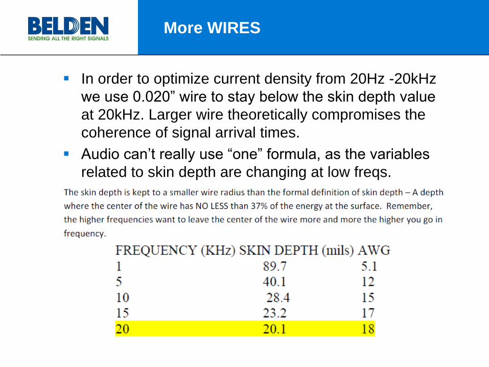
In order to optimize current density from 20Hz -20kHz
we use 0.020” wire to stay below the skin depth value
at 20kHz. Larger wire theoretically compromises the
coherence of signal arrival times.
Audio can’t really use “one” formula, as the variables
related to skin depth are changing at low freqs.

MORE ON ALL THOSE WIRES
To avoid interacting with speaker cross-over circuits, an
adequate AWG size is needed, so this means more
smaller wires to meet DCR requirements.
WHEN DO YOU STOP USING ALL THOSE
WIRES?
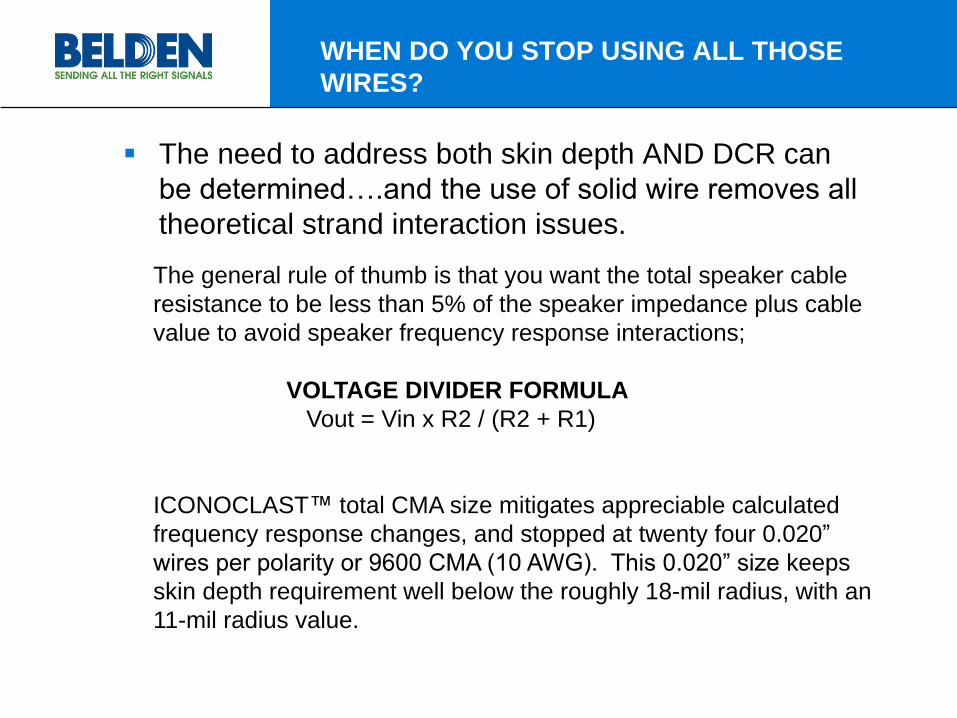
The need to address both skin depth AND DCR can
be determined….and the use of solid wire removes all
theoretical strand interaction issues.
The general rule of thumb is that you want the total speaker cable
resistance to be less than 5% of the speaker impedance plus cable
value to avoid speaker frequency response interactions;
VOLTAGE DIVIDER FORMULA
Vout = Vin x R2 / (R2 + R1)
ICONOCLAST™ total CMA size mitigates appreciable calculated
frequency response changes, and stopped at twenty four 0.020”
wires per polarity or 9600 CMA (10 AWG). This 0.020” size keeps
skin depth requirement well below the roughly 18-mil radius, with an
11-mil radius value.

48 wires!
We use 24 SOLID 0.020” wires per polarity to reduce
speaker frequency response to a practical minimum.
ICONOLAST™ cuts the calculated values of wire radius from 18-mils
to 10-mils, over half, and makes sure we theoretically utilize the wires’
cross section as efficiently as we can while managing all the other
variables.
Too large an AWG impacts ESL type speakers so you must
manage every other attribute effectively...and this is not usually
accomplished with an effective overall design once a reasonable
summed CMA wire size is achieved (10 AWG).
To avoid the consequences of speaker output response,
ICONOCLAST™ uses twenty-four 0.020" solid wires (10.0 AWG) per
polarity, or TWELVE bonded pairs. The smaller 0.020” wire allows
flexibility, while being small enough to force the high frequencies to
be more linear in velocity compared to the lower frequencies inside
the wire (fill the middle more with high frequencies), or improved skin
depth.

SKIN DEPTH AT AUDIO FREQUENCIES
Small, but meaningful?
There is a measured 6.75% change from 100Hz to
20kHz for Rs for ICONOCLAST™ speaker cable.
Results
Impedance
Ls Rs Cp Mag. PhaseµH/ft. mΩ/ft. pF/ft. ohms degrees
0.084 2.37 44.84 297.83 -43.81
0.080 2.37 44.69 98.09 -39.50
0.079 2.39 44.65 65.67 -32.43
0.079 2.41 44.61 50.89 -23.07
0.079 2.42 44.60 46.66 -17.17
0.079 2.43 44.59 45.00 -13.59
0.079 2.47 44.57 43.63 -9.80
0.078 2.53 44.55 43.12 -7.59
0.078 3.12 44.50 42.40 -3.70
0.077 4.65 44.47 42.00 -2.80
0.074 8.01 44.59 41.32 -2.42
0.071 14.04 44.45 40.46 -1.78
0.070 20.26 44.53 40.04 -1.31
Loop DCR (milliohms/ft.) 2.40
Units:
Freq. (Hz)
100
1000
2500
5000
7500
10000
15000
20000
50000
100000
200000
500000
1000000

Why NOT use larger and fewer wires?
This is a 1313A equivalent CMA wire design, with
fewer wires. There is a measured 71.8% change in Rs
from 100Hz to 20 kHz. Results
ImpedanceLs Rs Cp Mag. Phase
µH/ft. mΩ/ft. pF/ft. ohms degrees
0.125 2.27 17.13 460.63 -43.57
0.155 2.27 16.94 152.64 -33.36
0.154 2.30 16.87 112.22 -21.70
0.154 2.40 16.80 100.93 -13.16
0.153 2.57 16.77 98.06 -9.71
0.152 2.78 16.74 96.85 -8.00
0.150 3.31 16.69 95.49 -6.46
0.147 3.90 16.66 94.49 -5.80
0.136 7.30 16.57 90.61 -4.68
0.127 11.67 16.53 87.81 -3.97
0.121 18.35 16.58 85.43 -3.28
0.114 31.78 16.43 83.95 -2.40
0.111 49.24 16.40 82.15 -1.96
Loop DCR (milliohms/ft.) 2.27
Units:
Freq. (Hz)
100
1000
2500
5000
7500
10000
15000
20000
50000
100000
200000
500000
1000000

ACTUAL Rs Measured Values
MORE IS NOT ALWAYS BETTER,
WE MAKE IT BETTER!

MATERIALS MATTER
Why use FEP?
Lowest dielectric constant of solid plastic @ 2.15.
Low dielectric constants allow lower capacitance
designs for a given wall thickness.
High dielectric strength, over 6500 V/mil, allows small
wire spacing for Inductance.
Dissipation factor (energy loss rate) and Loss Tangent
(angle of the loss reaction to the electric field) are low,
but less important at audio frequency ranges than RF.

THE ICONOCLAST™ DESIGN ADVANTAGE
THE ICONOCLAST™ DESIGN MAKES IT BETTER
EVEN WITH ALL THOSE WIRES!!

It pays to NOT be different.
ICONOCLAST™ speaker cable DESIGN insures
every wire looks like the EXACT same wire in length
and electrical characteristics. The cable ACTS like two
wires.
The design uses a clever geometry to leverage the
necessary physical parameters to address critical
electrical parameters; skin depth, R, L and C.
The design benefits each unique attribute without
negative impacts on other physical or electrical
variables.

SOME THINGS LIKE TO BE CLOSE.
The average distance between each wire in each
polarity to ground is the same average distance, and
the same final capacitance.

IS EACH WIRE REALLY THE SAME?
BONDED PAIRS AND MACHINES ARE INDEED
CONSISTENT.
One wire to all others connected to ground;
Niehoff 6 x 6 PPI 4.0 Avg. pF/ft. STDEV Min Max
177.0955 177.4340 172.3321 179.0224 175.3815 2.4364 171.4507 180.1803
172.8369 171.4930 176.5402 176.5411
174.2683 175.2594 174.7609 175.8863
175.8969 178.0881 172.8248 179.1448
176.2732 171.4507 171.9916 176.7639
174.0600 177.8210 178.7609 173.1713
172.3291 177.8486 172.0927 173.2086
180.1803 171.7460 177.0839 175.2722
177.3002 173.0879 175.0548 172.6448
174.8771 176.2519 178.0202 176.1054
173.6109 177.2030 172.5906 172.4072
179.3871 176.1192 177.6033 176.5716

WE DON’T HAVE DIFFERENCES.
ICONOCLAST™ speaker cable design is a
symmetrical polarity design. Each polarity is
EXACTLY the same electromagnetic electrical design,
insuring truly balanced polarity signals, which
improves coherence.

BUT WHAT ABOUT INDUCTANCE?
The inductance of a single bonded-pair is about 0.196
uH/foot. But ICONOCLAST™ can do better than that.
When we use mutual inductance reduction by forming
the polarity legs into flat braided ribbons to collapse
the inductive loop area, and by placing them one on
top of the other, the inductance drops to 0.08 uH/foot
nominal.
Inductance tries to impede the magnetic field
generation with signal current flow, an important
variable in high current speaker cable design.

Negative Reinforcement!
Inductance control is managed by geometrically
arranging the fields to cancel one another as best
possible, and as CLOSE as possible (tight outer
braid).
100% inductive cancellation is unfeasible as the fields
would need to share the exact same spot in a wire,
and at the exact same time and opposite polarities.
Right Hand rule defines the electromagnetic field’s
direction and potential cancellation properties.
Management of the electromagnetic fields reduces
the overall mutual inductance of the cable.

How’s that work again?
The right hand rule defines current direction.
If the current is going left to right, the magnetic field is
counter clockwise to the current direction.
Imagine your RIGHT thumb is pointing in the current
flow, your fingers wrap in the field direction.
Twelve four wire groups, six per polarity.
BONDED PAIR ADVANTAGE
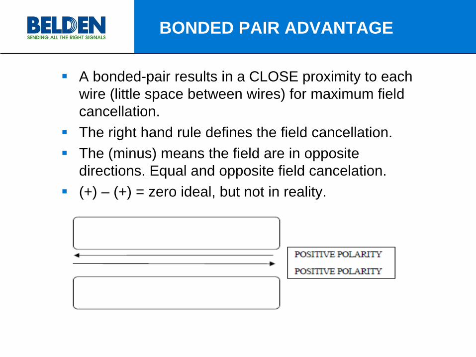
A bonded-pair results in a CLOSE proximity to each
wire (little space between wires) for maximum field
cancellation.
The right hand rule defines the field cancellation.
The (minus) means the field are in opposite
directions. Equal and opposite field cancelation.
(+) – (+) = zero ideal, but not in reality.
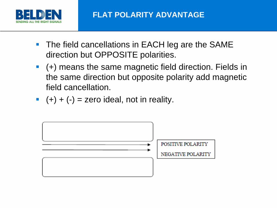
FLAT POLARITY ADVANTAGE
The field cancellations in EACH leg are the SAME
direction but OPPOSITE polarities.
(+) means the same magnetic field direction. Fields in
the same direction but opposite polarity add magnetic
field cancellation.
(+) + (-) = zero ideal, not in reality.
IS THERE MORE?
There is always more.
– Why even worry about capacitance if it’s not as
critical to high current (20-30 amps) speaker
cable?
– Phase shift claims are heard at ~ 10 degrees and
arrived at in lengths as short as 20-30 feet, and is
capacitive driven.
– Lower capacitance allows near zero degree phase
shift in longer lengths, up to ~200 feet @ 20 KHz.

HIGHER BANDWIDTH
– LOW CAPACITANCE = BANDWIDTH
http://www.electronics-tutorials.ws/filter/filter_2.html

What about my amplifier?
The low capacitance insures a zero phase operating
bandwidth, but the more likely issue isn’t bandwidth
influenced phase change, but amplifier instability into
high capacitance loads.
ICONOCLAST™ speaker cable’s very low
capacitance is designed to provide superior phase, as
well as to be as benign a load to amplifiers as
possible.
Zobel networks for stability aren’t necessary to protect
electronics except with very LONG leads.

PASSIVE RF CANCELLATION
IT PAYS TO BE CROOKED…SOMETIMES.
The complex looking braid forces like and unlike bonded-
pair polarity crossings. As wires cross at higher angles it
passively cancels RF energy through ELECTRIC field
cancellation.
This helps remove EMI/RFI frequencies you don’t want,
and to send only the signal that you do want.

EVERYTHING IS IMPORTANT
ICONOCLAST™ is a VERY unique design, and one
driven by the electrical requirements of audio;
SOLID SMALL 24AWG BONDED-PAIRS ARE
FLEXIBILE AND ALLOW CLOSE SPACING.
MANAGED SKIN DEPTH BY DEFAULT.
VERY LOW DCR - 9600 CMA / ~10 AWG SIZE.
VERY LOW CAPACITANCE (ESL / spacing of wires).
VERY LOW INDUCTANCE (Dynamic / spacing of
wires).
ELECTRICAL POLARITY SYMMETRY.
HIGH ZERO DEGREE PHASE BANDWIDTH.
SAFE CAPACITIVE LOAD FOR AMPLIFIERS.
PASSIVE EXTERNAL FIELD CANCELLATION.
EASIER TO USE COMPACT AND SLIM DESIGN.

SUMMARY
• Belden used real world DESIGN benefits to achieve a superior sounding
product with “passive” theoretical benefits.
• The DESIGN showed the most influence on the sound over exotic
materials, but the use of high quality plastics was necessary to meet R,
L and C.
• SMALL individually insulated bonded SOLID wires allow flexibility and
stable processing while mitigating theoretical strand interactions and
skin depth.
• Copper type is the only design change between ICONOCLAST™
cables, allowing true copper quality evaluations in YOUR system.
• Each assembly measured for; R, L and C.

CONDUCTOR QUALITY
OFHC C10100 copper used for conductor.
– The method of producing OFHC copper ensures extra high
grade of metal with a copper content of 99.99%
– We offer C11000 STD copper as the superior DESIGN allows
superb performance with modern drawn wire.
– ALL ICONOCLAST™ products (RCA, XLR and speaker)
share the exact same electromagnetic designs and materials
except copper grades so your own ears can be your guide
and not hidden in the design and material differences.
ICONOCLAST™ speaker cable is 100% symmetrical balanced conductor layout for positive and negative polarity, avoiding different reference conductor values for either polarity in A/C signals.
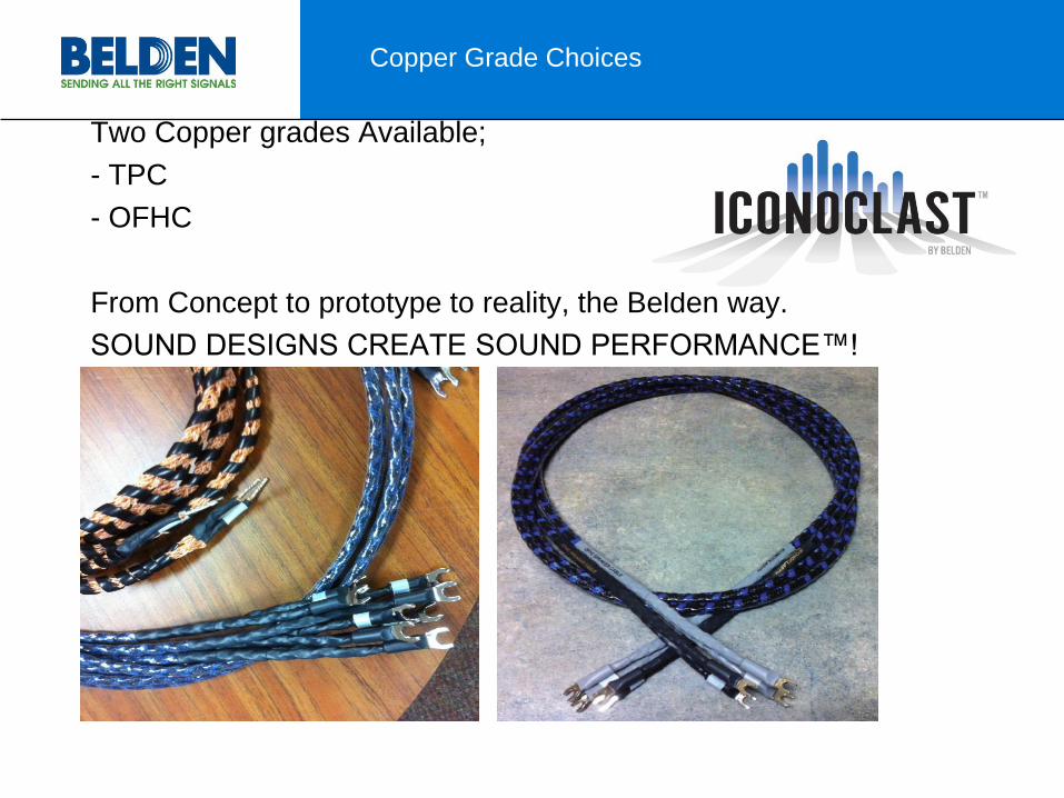
Two Copper grades Available;
- TPC
- OFHC
From Concept to prototype to reality, the Belden way.
SOUND DESIGNS CREATE SOUND PERFORMANCE™!
Copper Grade Choices