speal project: all band all mode hf transceiver save £700
TRANSCRIPT
AN ARGUS SPECIALIST PUBLICATION
SPEAL PROJECT: All band allmode HF transceiver Save £700! Easy to build modular construction No compromise performance Choice of specification! Complete kits available
OUFIL,
/100W
TESTING:ASSESSING:CONSTRUCTING:
RIALC/O
5WPA/QR P
PRE-SELECTOFILTERS
MIXER/IF TXRX/AF
ECH PROCESSOR
's new TS -930 WARC band heavyweightcondensed
W FILTER

PligligFFP WW 111111111111
IIIIIIIIIIIIIIIIIIIIII 111111111111111111111111111111111MMI 111111111111111111111111111111111111111111M/M/I1//1111111111111111111111111111111111111111111111111
////////////11/1111/ 11111111111111-1111111111111111111111111i11
1
a -CM
YAF.St1FT-ONE
Amcomm Peopleare at
the other end.
Who do you talk to when youcall Amcomm? Usually Jack G3LNC orAlec G5VS. Whoever it is, you'll be speaking to pleasantand reliable people with years of operating experience on theamateur bands. People with an intense and active interest ineverything to do with Amateur Radio. People who actuallyoperate 365 days every year. People who quickly and efficientlyimpart the information you need to make your decisions.
Just listen or ask around the bands - the reputation we havegained was built by people like you. People who have triedAmcomm and stayed Amcomm.
You see, we understand Amateur Radio, we live it at work andplay - but most important of all - we understand Amateur RadioPeople.
Call us today and ask about our 70 major amateur names whichmake up over 500 different lines or send 50p. in stamps for ourBumper Literature Pack. (You'll find enough reading for days!)
You'll certainly like the peopleat the other end...
Amcomm People.
Amcomm Services,194, Northolt Road, South Harrow,Middlesex HA0 2EN.Telephone: 01-422 9585 (3 lines).Telex: 24263.

*Li
EditorFrank Ogden G4JST
Assistant EditorRichard Lamont G4DYA
Advertisement ManagerNeil Terry
Classified SalesSally A. Collins
Managing EditorRon Harris
Managing DirectorT.J. Connell
Published by:Argus Specialist Publications Ltd.,145 Charing Cross Road,London WC2H OEE.Telephone: 01-437 1002.
Distributed by:SM Distribution Ltd.
Printed by:Q. B. Ltd.
Subscription Rate:UK £12.800/Seas Sur: £13.250/Seas Air £25.80Ham Radio Today,Sub Dept.,513 London Road,Thornton Heath,Surrey,CR4 6AR.
Ham Radio Today is normally published onthe- first Friday in the- month precedingcover date. The contents of this publicationincluding all articles, designs, plans, draw-ings and programs and all copyright andother intellectual property rights thereinbelong to Argus Specialist PublicationsLimited. All rights conferred by the Law ofCopyright and other intellectual propertyrights and by virtue of international copy-right conventions are specifically reservedto Argus Specialist Publications Limitedand any reproduction requires the- priorwritten consent of the Company. 1983Argus Specialist Publications Ltd. All reas-onable care is taken in the preparation ofthe magazine contents, but the publisherscannot be held legally responsible for er-rors. Where mistakes do occur, a correctionwill normally by published as soon as possi-ble afterwards. All prices and data con-tained in advertisements are accepted by usin good faith as correct at time of going topress. Neither the advertisers nor the pub-lishers can be held responsible, however,for any variation affecting price or avail-ability which may occur after the publi-cation has closed for press.
CONTENTS VOLUME ONE NO. 7 JULY 1983
REGULAR COLUMNSLETTERS 4RADIO TODAY 8NEWCOMERS FORUM 24TECHNICALITIES 35NEW PRODUCTS 47CLUB NET 55
CONSTRUCTIONPROJECT OMEGA: ALL MODE HF TRANSRECEIVER 10A new design for the ultimate in home construction
A SIMPLE BEAM FOR 10 METRES 30A Q50 is better for having made your own
THE RESISTANCE SWR BRIDGE 45The ideal bridge and dummy load for the QRP enthusiast
PROJECT OMEGA: AN ACTIVE SSB/CW FILTER 66An active replacement for a typical crystal filter
AERIAL FARMING AT HF 21Six years of practical observations condensed
USING 10 METRES 27Use it or lose it
VALUE FOR MONEY? 32Many specifications aren't worth the paper that they are printed on
RADIO MATHS FOR THE RAE STUDENT 40Part two of our series takes the pain out of swotting
QRX, I'LL JUST TUNE FOR A LOWER SWR 42Read the facts, not the fiction
VHF PROPAGATION 52You don't neccessarily need to be high to get out
TRIO TS -930S HF TRANSRECEIVER 59
NEXT MONTH IN HAM RADIO TODAY 51
HAM RADIO TODAY MORSE COURSE 65
EMPORIUM GUIDE 70CLASSIFIED 72ADVERTISERS' INDEX 74
HAM RADIO TODAY 1983 3

LETTERSS -METER SAGA
Sir, Your comment at the end of my letterprinted in the May issue says "End ofconversation". But you can't leave it there asyour statement is incomplete and thereforemisleading.
You say "Let OdB=0.5pV". Fine, butwhat notch on the S -scale should that inputrepresent? To what authority do you attributeyour definitions? I'd like to know if ITU,IARU, FCC or any similar body has producedan official recommendation about S -pointsand reference level. If so I've missed it.
The competition question in the Januaryissue that sparked off my initial outburstinvolved a power increase from 10 to40watts. The answer being sought was 1S -point. But, as already indicated, KW userswould measure I S -points. Should they befailed?
In the February issue G3WPO coversthe subject very well. The 1982 ARRLHandbook says that attempts were made tomake S9 equivalent to 501.4V and each S -unitequal to 6dB. This system never caught onprobably because of design difficulties suchas gain variations between bands anddifferent AGC performance from receiver toreceiver.
S -meters can give only an indication ofrelative field strength, not an absolutemeasurement thereof as commonly believed.In practice they are a mixed blessing to betaken with a pinch of theoretical salt.
RAY BURGESS, G3RXG
Sir, If I may update my last letter, I amindebted to the Editor of Practical Wirelessfor sending the enclosed IARU 1981recommendations for S meter calibration.This is the first hard evidence I have seen ofan official recommendation. It is interestingto note that the reference levels changebetween HF and VHF.
It is probably safe to say that mostequipment in circulation does not complywith these standards. These are recommen-dations, not regulations, and unless an equip-ment specification states that the S meterconforms to IARU standard, there can be noguarantee that it does, in fact the chancesare that it does not.
So I think most of my previous remarksare valid. I will continue to avoid anymisconceptions by giving subjective reports,but with just half an eye of my definitelynonconformist S meters.
RAY BURGESS
HF LINEAR
Mr. Ogden, I took great interest in yourarticle, 400 Watt HF Linear Amplifier inMay's edition of Ham Radio Today.
Please address correspondenceto:
Frank Ogden G4JSTHam Radio Today,145 Charing Cross Rd,London WC2 DEE.
I agreed with your argument that it maybe technically far easier at HF to obtain thelegal limit by using a relatively low voltagepower supply (say 1.2kV) and increasing thenumber of valves, however, it is my view thatit would be wiser and as economic toconcentrate on designing a power supplycapable of delivering 2kV+ andincorporating all necessary PA metering anda number of safety and valve protectionfacilities. Having constructed such powersupply unit, it should then be possible toutilise it with any single valve 4CX250Bamplifier designed for bands from 160metres through to 70cm. I would point outthat whilst the construction of a multivalveamplifier at HF is simple, at VHF the designof an amplifier with two valves or more isvery complex.
I have recently completed theconstruction of a single valve 4CX250B2 -metre amplier and associated powersupply. The power supply took six months toconstruct and develop whereas the amplifiertook only three weeks to complete.
The power supply was very cheap tobuild since all expensive components wereobtained from a Heathkit DX100U AM HFTransmitter which was purchased for £25.Prior to the advent of the semiconductor SSBera, many amateurs owned the DX100U, soit is not surprising that they are seen at mostrallies with a price tag of £20 to £35. TheDX 100U is housed in a 19" steel case with aslide -in heavy gauge 19" steel chassis which
linear amplifierusing single4CX250B built byStephen Lewis
is ideal for supporting heavyweighttransformers and chokes. The case was usedfor the power supply together with a 600V200mA transformer, a 1600V 500mAtransformer, a 6H 500mA choke, a 7H200mA choke, the panel meter, ceramicrotary switches and valve sockets,electrolytics, high wattage resistors andtoggle switches. For the HF operator thereare additionally all components required foranode and grid pi -networks, some SO239s, ahigh quality modulation transformer, two6146s and two KT88s.
Not bad for £25?
STEPHEN LEWIS, T.Eng (CEI). G8JCT.
OM, Yesterday I saw your HRT mag on sale,so I bought a copy, attracted by the 400WHF linear. I've been collecting parts for aG2DAF, but will try one based on yourdesign, as I think it will be more easily drivenby my FT7.
One point though: the grid circuit usesa 2:3 toroidal transformer. Will you pleasegive me details of the type of core, and thewinding details?
Second point: you have notincorporated any delayed switching of the1300V supply, whereas elsewhere I haveread that valves can be damaged if the FIT ison before the cathodes have reachedoperating temperature. Any comments?
I like the look of your magazine, as domy mates G3US and G3HCX. I like theexcellent typeface and the un-stodgy style ofpresentation. May you have much success inthe future.
WALTER FARRAR G3ESP
4 HAM RADIO TODAY JULY 1983

Yes, I've got some observations. First of all,thanks for the kind comments. But to thematter in hand. Yes, I've heard that valvecathodes can be stripped by prematureapplication of the HT supply. However theobserved facts don't fit precisely. I have anumber of old mains radios (they aresomething of a hobby with me) which warmup with HT present... they were designedthat way. No ill effects. Secondly, althoughthe HT is present all the time on my linear,the electron stream is cut off by keeping thegrid 1 bias volts on and taking grid 2 tocathode potential. This cut-off phase alsoapplies to the warm-up period.
It is interesting to note that you mustkeep the PA valves shut off during receivebecause the standing bias current causes asignificant amount of white noise on the otherside of the aerial changeover relay. Thiscould adversely affect the receive path noiseperformance.
Re. your query on the step-uptransformer in the grid circuit, that's just asimple autotransformer wound on a ferritebraid breaker' core. The core is a 1cmsquare of ferrite with two thin holes throughthe middle. The core is wound with a total ofsix turns of 24swg wire tapped at four turnsfor the drive input.
Frankly, the actual shape of the ferritecore used is relatively unimportant.Providing that the cross sectional area isequal to that of the average pencil, thepermeability is at least 200 (most are) then itshould be OK. Anything sold as a balun corewill almost certainly be suitable. I suggest a'suck it and see' approach. You can't do anydamage. Good luck - Ed.
NORTH SEA OIL RIGS
Sir, The Syledis navigation system, usedmainly in the North Sea by the oilexploration business, has caused problemsto UK amateurs using the 432MHz bandfor some time. Initially Syledis chains wereset up temporarily where and whenrequired, but subsequently installationsbecame permanently established. Thesepermanent chains do not transmitcontinuously, but are switched on auto-matically by a mobile unit requiring anavigational fix.
Unfortunately for the amateurpopulation, the 430-440MHz band is alloca-ted on a primary basis in the UK to radiolocation, with amateurs having onlysecondary status. The amateur populationhas therefore no right to demand thatinterference from Syledis cease. What isalso unfortunate is that the frequencies ofoperation chosen by the manufacture ofthe equipment, and subsequently allocatedby the Home Office, coincide with part ofthe DX Communication end of the432MHz band.
A paper presented at the Electronicsin Oil conference held towards the end oflast year in London gave some details ofthe system, and indicated the frequenciesused by the service. The frequenciesmentioned are 432.563MHz, 432.513MHz,and 432.463MHz for the Primary Group,and 432.383MHz, 432.303MHz and432.144MHz for the Secondary Group.
Although the Home Office have beenapproached about the situation, at presentthey are not prepared to alter the status ofamateurs on 432MHz. So for the time
being, UK amateurs are, by the terms oftheir licences, obliged to avoid thesefrequencies, so as not to cause interferencewith the primary service. I would begrateful if you could convey thisinformation to your readers so that theyare aware of the situation, and realisewhich frequencies in the band they shouldavoid.
MALCOLM APPLEBY G3ZNUCHAIRMAN, VHF COMMITTEE, RSGB
DISGUSTED, DEVON
Editor, I wrote to a component firm inBrentwood, Essex, to ask if they would letme have a key to the list of linear ICswhich they advertise. Of course theyreferred me to their catalogue; but whyshould one have to pay to find out whatthey are advertising?
Now if you would publish a list oflinears, showing what the things are for,you would please advertisers andconstructors alike.
JIM BOURNE
TELEVISION BANDWIDTH
Sir, I was interested to see the article onATV in the March issue. This seemed togive a fair picture of ATV as it is today,though I for one regret it. I have used ATVsince 1964 but am rarely on now, andwatch less and less as time goes on becauseover the last few years ATV, on 70cmanyway, has become largely a pointlessblack box activity with the usual black boxdisadvantages. That is, operation withminimum equipment and even less know-how!
Colour operation was mentioned but itwas not pointed out that operation withcommercially available transmitters onPAL colour is a contravention of thelicence conditions. You work it out: theytransmit a double sideband signal and aPAL signal requires over 4.43 (in practiceover 5.5) MHz of information. That is, thetransmitted bandwidth is in practice over10MHz, in a band only 8MHz wide!
In several cases, including the Fortoptransmitter, there is no provision for soundmodulation, either in the middle of thepassband or anywhere else, so use wouldrepresent another licence contravention.Now we all know that when it comes topolicing the bands - even on sound - theHO/PO are pretty incompetent so thechances of anyone being done for such abreach on television is fairly remote.However it would indeed be a pity if a lack ofinformation in a magazine article were to bethe cause of one of these unknowledgeableblack box operators losing a licence.
A JAQUES G3PTD
The notes on frequency checking equipmenton the back of the amateur licence say that"When determining the proximity of anemission to band -edge, the bandspread dueto modulation, on the appropriate side of thecarrier, needs to be added to the frequencytolerance of the carrier." So even the daftestof the daft need to take the bandwidth oftheir signal into account, whatever mode,television or not, they're using.
PAL colour signals can be contained inan 8MHz band by using a vestigial sidebandfilter, to cut off the high frequencycomponents in one of the sidebands.Although this technique is universal intelevision broadcasting transmitters I've seenno mention of it in amateur circles. However!wouldn't be surprised if the BATCcogniscenti solved this one years ago. I'd liketo publish a design for such a 70cm VSBfilter. Any offers? - Ed.
SHOCKING
Sir, Tut tut! How long have the ChannelIslands been off the tip of Cornwall? (Yourmap on p7 of Ham Radio Today, May 1983.)
You publish a great mag, but yourgeography is shocking!
H E HOGG
I cannot tell a lie. I haven't the foggiest ideawhy we printed the Channel Islands in such aScilly place - Ed.
PERSONAL PREJUDICE
OM, An excellent and thoroughly readablemagazine, spoilt only by the apparentpersonal prejudice of the Editor against theRSGB.
Reasonably low key in the first twoissues, this prejudice shows up very clearly inthe third.
The RSGB is a National Society (indeedthe only National Society) which representsthe interests of British radio amateurs. Theonly qualification for membership is aninterest in amateur radio, and no licence ofany sort whether Class A or Class B orwhatever need be held.
There are no faceless beings at RSGBHQ who control our destinies. Theadministrative staff who work there are thepaid employees of the Society, and the views,opinions, decisions and aims of the Societyare those of its members and of theirrepresentatives as voiced through the variouselected committees.
The RSGB membership embraces anextremely broad cross section of Society bothmen and women, young and old. Thetechnical abilities of some of its membersextend no further than the RAE whilst othersare in the top bracket of technical expertise.
It comes somewhat hard therefore tofind this large body of enthusiasts labelled as"benign", elderly and "fuddy-duddy". Now Iam a member of the RSGB, and whilst I mayadmit to being benign on occasion, andwhilst "elderly" may be a matter of opinion, Ido not consider myself to be "fuddy-duddy"and I extremely resent being so called.
Reference the RSGB being against ClassB CW on 144MHz. If this is true as you assertthen there must be a valid reason for it, otherthan the curious and selfish reasons whichyou, by implication, put forward.Furthermore if, as you claim, someconfidential information was "leaked" from aclosed committee meeting then it seems tome that the corrupt attitude of the personwho leaked it is equalled only by that of theperson who purveys it in print asunsubstantiated second-hand gossip. Itwould be interesting to know whether theRSGB was asked for its reasons regarding theabove before you knocked it so hard in yourcolumn.
HAM RADIO TODAY JULY 1983 5

Finally we come to the matter of the sixmetre licences. Requiring informed advice onthis matter (a concession obtained only bythe efforts of our National Society) to whomshould the Home Office turn? To whom couldthey turn except to the National Societywhich represents British amateurs. Some maysay they should have turned to G4JST theliberal -minded editor of our latest mag.Others may think it significant that they didnot.
If as you claim you have all radioamateurs' interests at heart then I suggestyou use your best efforts to persuade all newlicencees to join the RSGB. This gives usmaximum voice at the ITU conferences onfrequency allocation, whilst those who thinkthe RSGB unrepresentative can offerthemselves for election, thus bringing aboutthe 'change from within' which you yourselfadvocated in the February issue.
If you throw stones you must expect atleast some of them to be returned, althoughyou will notice that I am somewhat moreselective in my target.FRANK SIMPSON G3EFR
B -K OR G -M OSCILLATIONS?
Sir, Your article in the January issue, broughtback many memories and the letter from K VEntinger's reference to Eric Megaw (G6MU)reminded me of his lecture to the RSGB onMarch 25 1931, published in the T&RBulletin, July '31 (ten pages): ElectronOscillations and their Application to VeryHigh Frequency Communications. In this, thehistory of the development of electronoscillations was given. He summarised to twoforms as:Barkhausen-Kurz (BK): oscillations whosewavelength was determined by the electrodedimensions and potentials.Gill -Morrell (GM): oscillations whosewavelength depends only on the externalcircuit..
A British Patent was granted to Gill,Morrell and MWT Co (No. 108757). Anabstract appeared in Wireless World in anarticle Very Short Waves by P R Coursey (17Oct 1918).
The two different forms of electronoscillation was fully covered by Hollmann inProc. IRE Feb 1920.
It appears to me, that the cross -channellink was most likely to have been using G -Moscillators rather than B-K.At that time,however, all electron oscillations wereusually described as 'B -K type'. Eric Megawspent most of his working life at GECResearch Labs, now known as Hirst ResearchCentre, working on the generation of UltraHigh Frequencies and considerable work onthe electron oscillators preceeded his workon the split -anode magnetron, the CWIIproduced 50W at about 1.5 metres.
I do not now recall the valves used inthe cross -channel link, most were modified 'R'type, in which the anode and gridconnections were brought directly throughthe bulb - see attached sketch. I still haveone sample which looks as though it wouldstill operate. A simple self quenching super-regen receiver using an electron oscillator ispictured on page 3 of chapter 1 of the newedition of the VHF/UHF Manual. The circuitof this detector is attached. I hope thisinformation is of interest to you.
G R JESSOP G6JP.
MOSCOW MUFFLER
Mr. Ogden, Reference the article/review TheMoscow Muffler by T. Bailey in the May 1983issue of Ham Radio Today.
With all due respects, the details givenin this article about the so called'Woodpecker signals are not quite correct.Firstly, it is known that there are four RussianOTHR systems in operation and that thetransmitter power output is not 4 Megawattsbut varies between 20 and 40 Megawattsdepending on the degree of ionosphericreflection necessary for the function of OTHRstations.
It is not known for absolute certaintywhether the Russian OTHR systems are usingback scatter technique as employed by theAmerican CONUS-B OTHR or, forwardscatter as used by OTHR stations operatingin the Middle East and Australia. It is mostlikely however, that the Russian system usesthe back scatter mode, in which case iheantenna for transmission would of necessityhave a very narrow beam width andtherefore be capable of high ERP. The 'lowpower' experimental American CONUS-BOTHR at present operating has an ERP of100 Megawatts (confirmed by the USA AirForce Electronics Division at Maine). TheERP from fully operational Russian OTHRscould well be in the region of 200 to 400Megawatts.
With the Russian on -off pulse system thePRF is always 10 per second (100mSinterval) and the pulse width 4mS. However,the transmissions are not always singlepulses. For example, there are often shorttransmissions using a 4 pulse sequence(unmodulated) which are thought to be solelyfor ionospheric soundings; necessary withOTHR systems. In normal search and targetinterrogate mode, the pulses may be single ormultiple and also code modulated, eachpulse being 4 milliseconds with a spacing of5 milliseconds, that is leading edge toleading edge, when a multiple pulsesequence is used. These are also repeatedevery 100 milliseconds. Note that pulsetransmissions from other OTHRs (mostlyAmerican) use PRFs between 16 and 60 persecond and which are often frequencymodulated as well.Whilst the so-called Moscow Muffler devicemay be effective in reducing, or eveneliminating typical on -off pulse signals atone's own station it does not follow that the
station with which a QSO has beenestablished, will be receiving your signalsthrough this type of transmission; unless asimilar device is in use. This could well bethe case since Russian OTHR signals (Wood-pecker) are frequently heard just as stronglyand at the same time as say in Australia orAmerica as they are in the UK. Calling CQ ormaking any other form of transmission on thefrequency in use by one of these stations willcause no interference to them whatsoever, asall CW, FM, AM or SSB telephony andteletype transmissions etc. are converted intobroad band noise which is suppressed by theOTHR receiving system.
It should be mentioned that on -offRussian OTHR pulse transmissions can onlybe fully resolved for oscilloscope examinationof the de -modulated pulse formations andencoded modulation, by using a receiverwith a through bandwidth of at least 2 MHzand an oscilloscope with a wide band 'Y'amplifier. Spectrum analysis can and hasbeen used to reveal the nature of themodulation on the Russian pulsetransmissions.
Finally, it has been found that somenoise blanker circuits on communicationstype receivers will greatly reduce 'Wood-pecker signals', almost to the point ofelimination if they are properly adjusted.Whilst the amplitude of wanted signals isreduced somewhat, readability is stillacceptable although much depends on therelative strength of the wanted signals andthe pulse QRM. At high level, the bandwidthof 'Woodpecker signals can be in the regionof half a Megahertz or more.
F C JUDD G2BCX
FIGHT AGAINST TV LINETIMEBASES
Sir, I would like to raise the question of RFIand TVI and the recent USA legislationwhich requires the manufacturers ofreceiving apparatus to include filters to keepout the unwanted whistle, while admittingthe wanted signal.
I seem to recall hearing Timothy Raisonon this subject recently on the Radio 4 earlymorning programme discussing this subject.
We need a campaign mounted, to givethe amateur some protection under the law,but I cannot see the RSGB (which acts like an
6 HAM RADIO TODAY JULY 1983

old servant content to touch his forelock andmurmur "Yes master" to the Home Office)doing anything about it.
I would dearly like to known theopinions of other amateurs when they havehad the American legislation clearlyexplained, together with the background.
What about an article from you on thesubject 'The Other Side of TVI', which couldoutline the benefits to the amateur of havingthe law recognise that the transmission islegal but the receiver is faulty, and adetailed write-up of the history andachievement of legislation in the USA.
If you do not know much about thesubject refer to Hilary G4JKS QTHR.
BASIL CAINES G4PAY
Yes. What a good idea. I'll be the first to jointhe campaign against 'noisy' appliances.Anybody out there like to write an article onthe subject? - Ed.
CLANGERS
Frank, Ref. HRT May 83 page 15:
Should be
Whoever copied it out of the Radio Amateurs'Examination Manual should have checked.They also drew it incorrectly!
Later editions showed a transformercoupled amplifier. To simply correct theoriginal drawing would have been to admittheir mistake and that is something somepeople just cannot do!
Thank you for an interesting, if slightly'cocky' magazine. I enjoy the apparententhusiasm with which it is written.
RUSSELL KING G8YNY
Sir, please let me correct you on the RAEAnswers which are on page 7 of the Apriledition (Q2 on radio theory). The correctanswer should be C: Golf 2 Mike UniformRomeo, which is the correct NATO alphabetis use now.
Thank you for a very good mag.
FRANK MARAS
METREWAVE
Frank, In stating that the adoption ofdirectional antennae would reducecongestion on 2m (May issue) Jack Hummade no mention of the need for transmitterpower levels to be reduced. If they are notthen the area covered by each signal (andhence its effect on congestion) will be likelyto increase.
RICHARD CLARKE G8UNO
CW IN COLCHESTER
Frank, In Newcomers Forum (May issue),Tony Bailey G3WPO, page 22 line 5, saysthat CW is "little used by comparison".
Maybe so round some QRA squares;down this way (Colchester) it is used quitefrequently - there are CW learners' sessionsnightly on 145.225 F2A, 144.150 Al A,146.160 A IA, and others come on forgeneral rag -chew as well.
Although many sweat to obtain a Class"A" purely in order to go HF, others obtaingreat pleasure and interest in CW hereaboutson 2m and 70cm.
Best wishes for a very professionalpublication,
LES G4NOZ
HOT GEAR
OM, In the Technicalities column of theMarch issue of HRT, you are mentioning "hotgear", ie. when the chassis of the rig is hotwith RF. As I have been using all kinds ofmakeshift antennas, mostly long wires of justwires, as most of them have not been thatlong, I happen to know this problem verywell indeed.
My solution to the problem is simple. Iconnect a 1/4 wavelength of insulated wire tothe chassis of the ATU, insulate the other endthen route it out of the window or just alongthe floor. For multiband operation I use onewire for each band and tape them together. Ifirst saw this mentioned in an article aboutBCI and AFI, in CQ magazine many yearsback, and later I saw in Amateur RadioTechniques this same solution. In his article,G3VA said that this would also improve theradiation pattern of your antenna. I hope thatthis can help someone who has the problemof 'hot' gear.
SIGURBJORN BJARNASON TF3SB
MORSE TEST MELEE
Sir, I am an SWL who has passed his RAEand has just applied for a Sound B. I will soonfollow this with my Morse test and a Sound A.I read your magazine each month; at leastthose bits of it which are not devoted to theMorse Test Melee. (Letters most months).
I think that it is essential for every I -IFoperator to known the morse code. Whatwould happen if you suddenly heard the
could not understand it? It would be somepoor seaman who has had no reply on themarine distress frequencies and has tuned tothe first station which he has heard working.
Then he come in on top, desperate for somehelp.
If you can't read his signal you're goingto be worse than ruddy useless to the poorblighter. If your readers were really keenamateurs, interested in self training, theywould stop charping and learn the code.Remember the motto: Use it or lose it.Anyway if just one amateur saves just one lifebecause of his knowledge, it must beworthwhile all of us learning the code, just incase.
Having said all that, I do think that theLWC should press for a restricted use ofmorse on 2m for teaching and practice. Isn'tthat what it is all about?
P M YORKE
PS You must know what LWC means.
APPEAL
Sir, Amateur radio forms part of theprogramme of self -training within manyVenture Scout units but lack of finance limitsthe development of this interest in a newlyformed group such as ours.
We feel that there must be much idleequipment lying dormant and semi -forgottenin attics throughout the land, and frompersonal experience I know that it is apainful decision to accede to the XYL'sexhortations and 'throw it out'. If donating itto a worthy cause would lessen this pain wewould very much like to hear from you. Anyequipment or components thus receivedwould, to us, have a usefulness far exceedingits value.
On a personal note - good luck HRT -I have been patiently waiting for you foryears.
A MILLS G4KRV (for 29th Wigan VentureUnit) 38 Dunster Close, Platt Bridge, Wigan,Greater Manchester.
IT'S BEEN DONE!
Mr Ogden, Re. your comments on increasingthe usefulness of the Mizuho MX -2. It's beendone, and is called the Totsuko TR-2100M!This device lives in a case about the size ofthe ubiquitous FT290R, contains 10 AA sizeNicads, a 1W PA for portable operation,10W PA for fixed or mobile use and room forfive crystals covering the whole bottom megin 200kHz slices (the tuning dial has areduction gear).
Circuitually the two rigs are verysimilar, the 2100 sporting an extra IF stage(IF at 9MHz) and a more sophisticated,amplified AGC system.
The price? Somewhat less than yourestimate at £110 from a newly 'converted'emporium in Stetchford (Birmingham).
Purchased recently, after inspecting theNEC exhibition for anything better at theprice, the rig has produced 5 & 7 reportsfrom the Continent using an HB9CV at anadmittedly good site (about 160ft aboveground level) on the University of Astoncampus in central Birmingham.
I would be interested to see a review ofthis rig although I have not see it on saleanywhere other than the above mentionedemporium.
N H HIGHFIELD G6AUV
HAM RADIO TODAY JULY 1983 7

RADIOTODAY
News about amateur radio compiled by Richard Lamont G4DYA
MOULD spreadsThe Ministry of Defence's MOULDmobile radiotelephone system,which has been causing interfer-ence to amateurs on 432MHz inseveral areas of the UK, is on targetfor completion this year. Despitethis, the MoD says it does not yetknow how many of the remainingtransmitters will be on 432MHz.
In this month's Radio Today weinvestigate the background to theMOULD system.
Home defenceTwo years ago, the Government
decided to revamp its HomeDefence preparations. The newplans, which are detailed in theDefence Estimates, include a£7,000,000 contract with Pye Tele-communications for the MOULDsystem. Pye described the project ina press release in December 1981 as"mobile, single channel, all -informed, radio command andcontrol systems for each of the HomeDefence Regions of the UKmainland. The Commander of eachRegion will be able to talk directly tothe forces under his command fromhis headquarters, irrespective ofwhether those forces are still in theirpeacetime barracks or deployed tooperational areas. The all -informed,mobile communications available tohim through MOULD will allow theCommander to exercise effectivecontrol over military operations inhis Region.
"In order to provide the widearea of communications coverrequired in each Region, it has beennecessary to adopt acommunications system similar tothat used by local authorities, policeand fire services and other agencies
such as gas and electricity boards.These rely on a network of staticrepeater or talkthrough stations,situated on suitable high groundand linked together to provide thenecessary degree of intercommuni-cations. In MOULD there are to beover 100 of these sites, located onexisting military establishments orsharing facilities with othergovernment or local governmentagencies. A limited capacity toexpand the system or to replaceunserviceable fixed sites will beprovided using Land Rover -bornemobile repeaters.
"The MOULD user will beprovided with a simple -to -operatecommercial radio equipment whichcan be used as a desk -top, a mobileor a portable station, depending onthe installation kit provided. Manyradios will be provided with morethan one installation kit so that thesame equipment can fulfill morethan one role."
The Home Defence Regioncovering London was the first to getMOULD in late 1981. Other Regionsfollowed during 1982 and 1983. Bythe end of 1983 all Regions shouldbe equipped.
What is it for?
It seems reasonable to assumethat in wartime the Army would berather busy. Yet there are a numberof Home Defence duties that itwould have to carry out, as well asfighting the war. Such tasks includethe guarding of 'key points' (ie.protecting important installationsfrom sabotage) and providing'military aid to the civil power'(stopping riots etc.). The regularbits of the Army would have theirhands full, so tasks like HomeDefence would presumably be
carried out by odd bits of leftovermilitary like the Catering Corps.These odd bits of military havewidely varying and incompatibleradio systems. Some have no radiosat all. MOULD appears to fill thisgap.
EDITOR'S NOTE
Our object in publishing this story is tobring to the attention of the readershipthe growing number of incursions intothe amateur radio frequency allocations.Our intention is not that of mischief mak-ing. What the Military decides to do inits own exclusive bands is not ours, oranyone else's business.
However, if the MoD or Home Officedecides to place a covert communicationssystem in a section of what is, after all,a public broadcast band, then it must expectthe presence to be noticed and noted.Furthermore, our responsibility for amat-eur radio interests compels us to bringany further incursions into the publicview.
G4JST
Why 432 MHz?
One question that is often askedis "Why did the MoD stick anallegedly classified system into oneof the most public bits of the radiospectrum?". One possible clue liesin the choice of Pye as the supplier.(Military radios are usually made byfirms like Racal and Plessey.) Pye'sdescription of the equipment as"simple -to -operate commercialradio equipment" suggests the useof standard PMR-type equipment,which is not normally made formilitary frequency bands (eg. the230-420MHz chunk). MOULD mayhave been stuck in the 432MHzband simply because PMRequipment could be used, at muchlower cost than equipment speciallymade for the military frequencies.Such economies have been acommon feature of Home Defencepreparations in the past.
Interference
Amateurs who have studiedMOULD report considerable inter-ference - to both amateurs andMOULD itself. The transmitters thathave been heard on the 70cm bandare listed in Table 1. Thesetransmitters are reported to beinterleaved with the amateurrepeater output channels by a121/2kHz offset. The Winter Hilltransmitter, which apparently cameon just before Christmas with about500 watts, is said to have madeGB3LL unworkable in parts of
8 HAM RADIO TODAY JULY 1983

Merseyside. The UK FM Group(Western) reports hearing femalevoices using Army RT procedureson the system. They also reporthearing Pye personnel testing thesystem.
One source suggests thatMOULD will provide each of theRegional Military Commanders withnational coverage. This would bedone by linking a MOULD site to theappropriate headquarters by aseparate radio link or landline. Thisseems to explain why some siteshave been heard using severaldifferent frequencies.
Unofficial secrets
In spite of the Pye press releasealready quoted, and coverage in atleast one national newspaper as wellas technical magazines, the RSGBclaims it has kept quiet about thesystem "because there's a D-noticeon it". Radcom describes MOULDas "Project X".
In fact, the only D-noticerelating to MOULD is a general oneasking journalists to consult with theSecretary of the Defence Press andBroadcasting Committee (that'swhat the 'D' stands for) beforedescribing any new militarycommunications system. (The wholeD-notice system is in any casemerely an informal arrangementbetween the MoD and the media toprovide guidance for reporters. Itcannot censor a story, andcomplying with D-notices does notprotect reporters againstprosecution under the OfficialSecrets Act. It has no legal standingat all.)
Allocations
In Region 1 of the ITU, whichincludes the UK, the 430-440MHzband is allocated on a primary basisto amateurs and radio -location. Thiswas decided at WARC 79. There is afootnote allowing the UK andseveral other countries to use theband for radio altimeters on asecondary basis, but not for fixedand mobile services, which lost theirallocation.
Individual governments areallowed to use bands outside4-27.5MHz for services not listed inthe WARC 79 frequency table. Theymust, however, notify the Inter-national Frequency Registration
Board (IFRB). The UK Governmenthas only just notified the IFRB ofMOULD, which is a fixed/mobileservice.
Also, if an individual countryuses a frequency for a service not inthe WARC 79 table, it must ensurethat it does not interfere withservices in other countries that arein the WARC 79 table.
So if MOULD interferes with,
say, a Dutch amateur repeater, thenthe UK Government would have totake steps to prevent theinterference.
A spokesman for the HomeOffice says they have not receivedany complaints about MOULD fromabroad. He says that if they did theHome Office "would take steps tomake sure the interference did notoccur". Watch this space.
Site
Winter Hill
Allport Heights, DerbySutton Common, Derbys? (Humberside)Barkway, HertsBentley Priory, MiddxColdblow Farm, Kent
Old Pale, Cheshire
Frequency
433.0125433.1625433.0125433.2125433.2625
? --
433.3625433.3675433.4625433.1625?
Site Frequency
? (Heard in SE England) 433.1375433.1125433.1875433.3125433.3875
Barnacre, Northumberland --- ? --Knightsbridge Barracks, London
433.2125
Table 1. Suspected MOULD sitesand frequencies in the 70cm amateurband.
IN BRIEF'HAM' MAN JAILEDAnthony Lavelle, a partner in HamInternational (UK), has been jailedfor nine months for importing illegalCB radios. £1,000 costs were alsoawarded against him.
His brother John Lavelle, also apartner in Ham International (UK),received a sixth month suspendedsentence. He was also ordered topay £1,000 costs.
Mr Christopher Holland QC,prosecuting, told York CrownCourt that they imported nearly£1,000,000 worth of illegal CBsets from Belgium, hidden in secretcompartments behind thebulkheads of two lorries.
Mr Gilbery Gray QC, defendingthe Lavelle brothers, said theythought the Government wouldlegalise the imports.
23cm NEXT ON MoD LIST?Amateur stations using the recentlyreduced 23cm amateur band can expectincreased interference from new airtraffic control radar stations, both civiland military. Several new radars arebeing built in the UK, and others aremoving out of the 582-606MHz band(between TV bands IV and VI to the23cm band.
LICENCE FEES UPThe cost of an amateur radio licence isgoing up by 50% to 12 pounds, from1st June 1983.
NEW UK PREFIXESThe Home Office has announced thatthe GO (G zero) prefix will be used forClass A amateur licences when the G4series runs out. Likewise the G1 serieswill be used for Class B licences whenthe G6s run out.
TWO MORE ON 50MHzTwo new stations have been issued with50MHz research licences, in place oftwo of the original forty who wereunable to operate. The new stationsare GW3MHW and GM4IGS.
AMSAT LAUNCH DELAYEDThe launch of the AMSAT Phase -1116satellite has been delayed by one to fiveweeks because of a problem with theengines on the launch vehicle, Ariane 7.
WRONG PRICEWe would like to apologise to SMC(again) for getting a price wrong in theiradvert in the June issue. The YaesuFT726R multiband, multimode VHF/UHF transceiver costs 649 pounds,not 6489 pounds as stated.
HAM RADIO TODAY JULY 1983 9

ALL MODETRANSCEIVER
By Frank Ogden G4JST and Tony Bailey G3WPO
In the beginning . . .
This magazine was launched someseven months ago with a series ofthree articles entitled A synthe-sised general coverage HF trans-ceiver. The idea of a home madebox which offered a comparableperformance in its basic facilities tothe off -the -shelf product created asubstantial amount of interest.However, there were a number ofshortcomings in that original seriesof articles which made duplicationof the project rather difficult.
I designed the originaltransceiver some three yearsbefore this magazine came into ex-istence purely for my own amuse-ment. Some people do crosswords,I make radio equipment. As a
result, the documentation wasnever intended for passing on tothird parties. In particular it lackedthe detailed artwork necessary forPCB manufacture. Although someerrors occurred in the published cir-cuits a number of sets were madewhich continue to perform satisfac-torily. However it became clear thatthe majority of interest in the pro-ject was in adapting bits of the cir-cuit to people's own requirements.
The result of all the lessonslearnt from the earlier project is
Omega. This brand new design hasvirtually nothing in common withthe original project. It uses differentcircuit technology, a completelynew design approach, offerssubstantially improved perfor-mance parameters, it can be usercustomised but - most importantof all - the whole project can beconstructed on ready made PCBswith easily available components,guaranteeing the reproducabilitythat is lacking in most publisheddesigns.
G4JST
PROJECT
5-4
Project Omega is to bemore than just an allmode, all band HF
transceiver system. Themodular concept
behind the designmeans that it can be
built to any userdefined specification
without spending timeand money on facilitieswhich aren't required.Omega covers everyneed from a single
band SSB receiver to anall mode, all band
transceiver featuringthe essential bells and
whistles of £1000+Japanese boxes.
Furthermore, you willbe able to build fromreadily available kitsand update as you go
along.
A new concept
The Project Omega HF transceiversystem is modular. This means thatany Omega module can be assembl-ed and tested as a complete unitbefore progressing to the construc-tion of other modules in the system.It also enables particular aspects ofOmega to be adapted to other uses.For instance, the FM board could beused with a number of commercialtransceivers as an extra facility. Orthe IF central processing systemcould be used as the heart of a highquality 2m or 70cm transceiver. It ispossible that a VHF/UHF customis-ing pack will be available in thefuture. However, the initial scope ofthe project will encompass all theamateur bands 160 through to 10metres.
Every module is rigorouslytroubleshooted and thoroughlytested before publication in thesepages. We aim to build three proto-types of everything which appearsin print to ensure that you don't haveproblems when you come to buildyours. To give some idea of theamount of work which is going andhas gone into the project, the IFcentral processing system publishedin this issue has occupied some 450man hours of work.
Omega modules
The following is a list of presentor planned modules:
Central IF processing module:comprises Schottky ring mixer,noise blanker, static crash remover,BFO, product detector, CW carrieroscillator, AGC system, AFamplifier
Notch filter: 50dB phasingcrystal notch filter
CW filter: active variable band-width CW filter equivalent to at least
10HAM RADIO TODAY JULY 1983

four poles of crystal filteringSynthesised VFO: provides
high level local oscillator signal( + 2.3dBm, 13dB pad) for up to ten1MHz wide user defined bands.Digital readout and analogue styletuning. Single loop system providesoutput 10.7MHz above signal fre-quency for single conversion IFsystems
SSB generator: USB/LSB signalat 10.7MHz for injection on CIFPU
FM board: detection andgeneration of NBFM. Interfaces withCIFPU
AM board: AM signal generatorand full 6kHz AM receiver sub-system
Speech processor: for use withall voice transmission modes. Im-proved baseband system withVOG AD
Logic control unit: enablesVOX changeover and full CWbreak-in capability. Copies betweendots at up to 40wpm+.
Preselector filter: single con-trol lowpass filter based unit
TX PA QRP: 5W powerMOSFET system. Full ALC forhands-off operation. Acts as driverfor
TX PA QRO: 50/100W PEP out-put system. Full ALC
PIN switch: PIN diode aerialchangeover system for use with CWbreak-in operation
Output filter: operatedautomatically via bandswitch
With a system as ambitious asOmega, it is impossible to publishdesigns for all of the modules in onego. We estimate that availability willbe one per month. What we do pro-mise is that nothing will be publish-ed until it is fully debugged andready to build. We aim to start witha core receiver system: CIFPU,VFO, Preselector followed by PAsand SSB generator. This also givesyou a chance to get each modulebuilt, tested arid debugged beforestarting on the next..
To give a better idea of what thesystem is about we have included anumber of possible Omega permu-tations. See Figs. 1 to 4.
Central IF processingunit
The theory of operation wasdescribed generally in theTechnicalities column of the Aprilissue. We won't therefore go into thesubject in great depth but simply
OUTPUTFILTERS
PINSWITCH.
LOGIC CONTROL.FULL CW BREAK INVOX CHANGE OVER
CW KEYING
TO ALL CIRCUITS
.....1 PRESELECTORFILTER
-4
T' 1,450 00/1
TM 0
PINSWITCH
Tx PA5W/ORP
ALC
SYNTHESISEDVFO
VARIABLEBANDWIDTHCW FILTER
SSB/CW R.MIXER, IF, NOISE BLANK R
AF OUTPUT, CW CARRIER OSC,PRODUCT DETECTOR
SSBGENE ATOP
FN1 AMBOARD BOARD
SPEECH ROCESSOR
Fig 1. G4JST/ G3WPO Omega transceiver system
note a few aspects concerning theoperation. A number of changeshave been made to the original cir-cuit as a result of prototyping.
Fig. 5 shows the block diagramof the module. The incoming signalis converted to the 10.7MHz IF bythe ring mixer DBM1. The roofingfilter comprising IFT1 and 2 limitsthe bandwidth of the signal beforepassing it to the IF pre -amp Q 1.Here, the signal path splits into two.The main path passes through thenoise blanker switch D2, D3 and Q2to the high quality SSB filter F2 via adelay line F 1. The delay filter F 1gives the noise blanker switch achance to open before interferencespikes can hit the main filter, F2.
The other signal path travels tothe noise blanker side chainamplifier Q8, Q9. These twoMOSFET amplifier stages raiseinterference pulses and crashes to ahigh enough level to turn off Q2following rectification by D4 and 5.
Cutting the rubbish
This noise suppression circuit- block diagram detail in Fig. 6 -received as much development time
as the rest of the IF system putogether. The result is excellent. Ittakes out interference of the 'wood-pecker' variety completely just leav-ing 'holes' in the signal. It is quitepossible to copy a2 SSB signalsthrough S9+ 30dB woodpecker. Tooffer some idea just how effectivethe overall system is, we spent sometime one afternoon just trying to findthe woodpecker until we discoveredthat we had left the noise blankerswitch 'on'. It also takes out randomignition noise and household in-terference such as the switching ofdomestic central heating ther-mostats.
Another pair of dual gateMOSFETs provide the main bulk ofIF amplification (Q4, 05) beforepassing the signal to the productdetector (Q6) and the AF amplifierIC 1.
The AGC generator IC2, D7and D8 provides a direct AGCsignal to the IF amplifiers anddelayed AGC to the IF pre -amp.The S meter signal, derived from theAGC line can be applied directly tothe meter, or through an optional6dB/division correction network (tobe detailed later). The AGC decay
PRESELECTOR
FILTER
SYNTHESISEDVFO
MAIN IF BOARD
Fig 2. Minimum configuration amateur band receiver system
HAM RADIO TODAY JULY 1983 11

12V
CM
C34
>4-1 *1
C177,1R19,
Q5
R35
R36
T
TC35
INPUI
F2
OUTPUT
C14
IFT5 = c 8
T IFTl
(§)
ijR21C20
ff
C37
r12:g72101
C1O
Ic57.1
C2
-t A
R26
R25C23 F
R29
R72 C2
C6
F1413
LINK R49
X = LEAD SOLDERED TO TOP FOIL OF = FERRITE BEAD ON LEAD
is continuously variable through afront panel control.
The phasing notch filter ismounted on a separate circuit boardand can ofthe CIFPU board. The 50 ohmsystem produces a 50dB notch whencorrectly adjusted. RV1 is for fineadjustment on notch depth. If thefilter is not required, simply bridgepoints. B and C.
CW only
In its uncustomised form, theCIFPU comes equipped to operateprimarily in the transmit andreceive CW mode. A BFO and TXcarrier oscillator (Q12 and Q10/11respectively) are standard equip-ment. In many ways the basicOmega system answers the basicquest for a high quality CWtransceiver system. It can be furtherdedicated to the mode by fitting anactive variable bandwidth CW filterbetween points E and F. See page66 for constructional details of thismodule.
Note that the transmit signal in-jection point for all modes is pointK. In transmit the grounded gate IFpre -amp 01 acts as a sourcefollower to the ring mixer circuit.
Sidetone for CW transmit is sup-plied by mixing a little of the keyedcarrier oscillator output in the pro-duct detector.
CONNECTION PIN
A philosophical note
It might seem rather regressiveto have used, in the main, discretecomponents in the CIFPU. Thereare a number of ICs from bothPlessey and others which can per-form many of the functions. Wemake no apologies for this.Although the Plessey 16(X) range ofICs is without doubt the finest in theworld, they are quite expensive andcan be a little fiddly to use in thehands of inexperienced builders.There is another point. Discrete cir-cuitry allows the designer to opti-mise on the features which he con-siders the most important. It wouldhave been difficult to match thelevel of noise blanker performancewith present IC technology. It mayalso have been difficult to provideenough circuit versatility which isthe intended hallmark of the Omegasystem.
Kits
As this series progresses, com-plete kits of parts will be availablefrom WPO Communications foreach of the modules described. Theboard kit for this IF module, com-plete with drilled PCB, all com-ponents, potentiometers, wire etccosts 5.69.50 inclusive of VAT andpost Sr packing. It does not include a
IFT2 I
R5R71-**.
CS
Rif 143462
C30
DBM1
.iav R31
C32
C60
147-- 12V
SX CASE SOLDERED TO TOP FOIL
speaker, the meter or diecast boxwhich you may already have. Thediecast box specified is alsoavailable at £5.50 inc. PCBs areavailable separately at £6.50 inc.
General notes onconstructing thetransceiver
Before starting this, we stronglyadvise you to use the PCBs available- you can then be fairly sure thatthe units will work as well as the pro-totypes. An awful lot of developmentwent into the boards to get themright - for instance, this IF unit re-quired three layouts just to get theWoodpecker blanker working cor-rectly - the layout is critical inplaces and using ready-made PCBswill save you having to sort out theproblems all over again.
Can I build it?
For those who are wondering ifthey can build this whole project,we would advise that it is notsuitable for absolute beginners whohave never used a soldering ironbefore, or who cannot understandthe basic descriptions of the cir-cuits. If you fall into this categorythen you should leave it until later,or make sure that you have a friendwho can help you out.
12HAM RADIO TODAY JULY 1983

ang rice Itoa fee most firaor of ail
epistles feedback a Orelib operston The vihm pointth. grounded gem mode 'a
Input alpurely reerstive provrsomehon for any lee
mope/ from 11'71 alin the recnon oft!
The FET shouldtens The peremtq
this a deetol.
or English 10 to 18 na 'V As corn den,* Th.10, or s few comments u -
pats lade. 1 always rhinos myselt make aboui the .ratv roc Nra
of some spate youth eornewhme in Nally 'nth grounded oaks 1 thou,d
the development labe of Sibcon be pod that Effer1rset it ,s .r my
medvertently pahratemno receive mode In usnseut tror TX
known cmt mewled onto the get. 1.,1
tow, and
Assembled main IF board
Wherever possible, prewoundtransformers have been used. Theseare also pre -aligned, which reducesalignment time. Detailed instruc-tions are given for the transformersthat you will have to make foryourself.
The instructions for assemblingeach unit will be as detailed as
amongst you can skip over parts ofthe text), and will include where tolook for any problems that may ariseduring testing. Long instructionsdon't necessarily mean that a unit iscomplicated - they are there forthe benefit of less experienced con-structors.
Test equipment
For alignment, you will need ahigh impedance voltmeter, andpreferably a signal generator
.boa,
plots* blank.tap kt copy wou tv
terestence N.,b AU... Mot. pot' I., :t
en. Ind the me,--4...red soul thvncleau
s the tCanova.
elip A. should not imps,.,,uty to handle normal
capable of running to at least10.7MHz - borrow one if you don'tpossess one! If you own or can bor-row a scope all the better. A fre-quency counter would be useful attimes, although the transceiver hasits own digital readout (ready built)which can be used. We will showhow to align it without full testequipment, although you do need asignal generator of some sort toalign the noise blanker in this IF unitsuccessfully.
The finished transceiver will behoused in a readily available com-mercial case. To help you get a pro-fessional appearance after all yourhardwork, there will be a readyscreened overlay or panel availablefor the unit if there is sufficientdemand.
This IF strip obviously needs aVFO to receive any signals! It canbe tested using a signal generator(or any other oscillator) as a VFO.
TRS
SYNTHESISE -0VFO
H PRESELECTOR
FILTER
811"T"Ca
FIRENITCN
TT PA
INV/CIRP
Fig 3. Minimum configuration CW only transceiver
VAR ABLEBANDWIDTHCW FILTER
IF strip constructionIf you are building the whole
transceiver, then the complete PCBassembly is required. For receiveonly, the TX 10.7MHz oscillator(Q10/11) and associated com-ponents can be omitted. beforelaunching into the assembly, checkthe PCB for any solder bridges aris-ing from the roller tinning process.These may not be obvious aftersoldering components in.
Note that the notch filter circuitis on a separate PCB, which will bedescribed next month, so we haveignored the components associatedwith it for the present.
One of the semiconductors (Q2,VN2222T,M) is sensitive to static sohandle it by its body not its leads.Alternatively push the leadsthrough some aluminium kitchenfoil before use, and remove themafter soldering. The MOSFETs(3SK45 or equivalent) do not needany special handling other than anearthed soldering iron. make sureyour soldering iron is well earthedor is a low -leakage ceramic sheath-ed element type. Also, the SBL1double balanced mixer must on noaccount have any DC applied to it,or it will probably fail rapidly.
Order of assembly
We suggest you follow the ordergiven here when assembling - thiswill ease assembly in some tightareas, and give you reference pointswhen inserting components.
One of the errors made by manybeginners in assembling this sort ofPCB is leaving too long a leadlength above the PCB. This can leadto instability and unwanted signalpick-up. Virtually all the capacitorscan be pushed far enough into thePCB for the lower part off the bodyto either rest on the surface, or haveleads no longer than 3mm, withoutdamage to the capacitor - if theywill go against the PCB then letthem. The same applies to theresistors and semiconductors.1) First, insert all the lmm connec-
tion pins into their respective holesfrom the underside, and solder theminto place. Each point where a pin isneeded is identified by a letter onthe upper surface of the PCB. Theyneed to be pushed hard home so thatthe splines are inside the hole.2) Insert and solder IC1 (LM380N)and IC2 (741), observing orienta-tion. Solder all pins on the under -
HAM RADIO TODAY JULY 1983 13
RFINPUT,
OUTPUT 1
RV4
InNOISEBLANKLEVEL
C3810n
FERRITE BEAD
CS
DBM1 In0POINT A
NOISE BLANKERCRAW
S1311
IFT1
12V 12V R. 12V T.
CSB ± C59 CRC I1(KM
CIlOp
IFT2
OISE L ER SWITCH
.1/42.1".. 12V R
R44100R
C42R45 100p1008
B
3SK51
DeBA379
CU1n0
0 0-
C9 -.100n
R5 T 1IMO
R473ROR
010
R413SBOR
R4922R
ST ALF1
C17100n
12V
R6220R
R7220R
R114700
C13100r F2
T21
12V T.
R55220R
053391,
K210 7MIlx
j.ZVC2airSUENCVADJUST
1N914 Ike
lOn
R341k0
TI
1
BEDADJUST
VC310-601
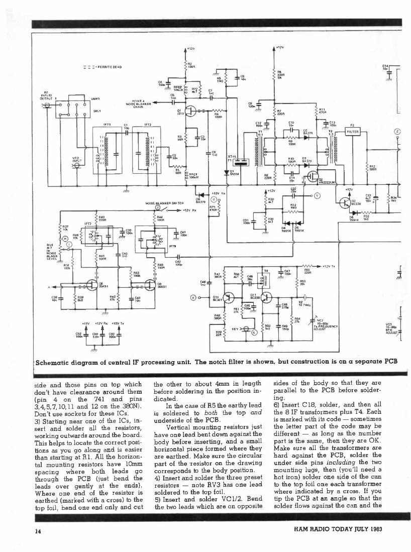
Schematic diagram of central IF processing unit. The notch filter is shown, but construction is on a separate PCB
side and those pins on top whichdon't have clearance around them(pin 4 on the 741 and pins3,4,5,7,10,11 and 12 on the 380N).Don't use sockets for these ICs.3) Starting near one of the ICs, in-sert and solder all the resistors,working outwards around the board.This helps to locate the correct posi-tions as you go along and is easierthan starting at RI. All the horizon-tal mounting resistors have lOmmspacing where both leads gothrough the PCB (just bend theleads over gently at the ends).Where one end of the resistor isearthed (marked with a cross) to thetop foil, bend one end only and cut
the other to about 4mm in lengthbefore soldering in the position in-dicated.
In the case of R5 the earthy leadis soldered to both the top andunderside of the PCB.
Vertical mounting resistors justhave one lead bent down against thebody before inserting, and a smallhorizontal piece formed where theyare earthed. Make sure the circularpart of the resistor on the drawingcorresponds to the body position.4) Insert and solder the three presetresistors - note RV3 has one leadsoldered to the top foil.5) Insert and solder VC1/2. Bendthe two leads which are on opposite
sides of the body so that they areparallel to the PCB before solder-ing.6) Insert C18, solder, and then allthe 8 IF transformers plus T4. Eachis marked with its code - sometimesthe letter part of the code may bedifferent - as long as the numberpart is the same, then they are OK.Make sure all the transformers arehard against the PCB, solder theunder side pins including the twomounting lugs, then (you'll need ahot iron) solder one side of the canto the top foil one each transformerwhere indicated by a cross. If youtip the PCB at an angle so that thesolder flows against the can and the
14 HAM RADIO TODAY JULY 1983

10n
ON A SEPERATEje FRONT PANEL PCB
T3
X110.7MH:
VC110-60PNOTCHFRED
R1615R
RV1ICIOR
C16100n
O
'12V
01172208
IFT5
`III I
C1815p
1074
10n
R35 R36100k 100k
R1915OR
R18100R 1076
05351(51
C19+1
C2047n X
17On
IIII
1 1
I 1
11
I I
S
a
C3C,36 In0
RV3220R
SIDE TONE LEV L
R23100k
0121147001
11212k2
C221u0
+ 25V
F122220R
35651
R245608
421 C23 e
25V10u
C2422n
R2515k
070C23$
R60220R
O
RV510k
S METERZERO ADJUST
R52101.
(0)
S METER1000A
01325655
RV8100k
CALIBRATE R83106
D71N914
R84100k
fit
081N914
0RV8IMOAGCDECAY
0534u725V C54
T414'17"
R26220k
12V
R6510k
00 )
180El
VOLUME
C222:
+I C251013016V
12V
C57100n
ICILM380
3 d,5,7,1011 2
R27151.
C55220nPOLY
R661k0
RV710klinMANUALIF GAIN
R67220k
C2810u
IR70
1k0
C5610u2SV
IMO
8 +
C29
AA 16v C)1g LS1
4-8
C30100n
PCB at the same time you shouldn'thave any problem. Don't adjust thetransformer cores.7) Insert and solder all the diodes.The spacing varies on these a little,but they all mount flat against thePCB. D9 has one end earthed to thetop foil, and should have shortleads. The PIN diodes may not bemarked with ident numbers but theyare square black packages with asilver line at one end, and fairlyfragile leads.8) Insert and solder RFC1 and 2(green, marked 101 plus a letter).9) Starting at one corner of theboard, insert the capacitors. Thosethat have one end earthed have the
lead bent up and cropped to 4mmbefore inserting and soldering intothe position shown. Note that someof the capacitors have their earthsmade via tracks on the underside ofthe board, and may appear not to beearthed because they are not shownwith crosses on the layout. C25 Sr C8are cases in point. Where acapacitor has an earthed lead butthe diagram does not show an ex-tended lead to solder, both leads gothrough the PCB, and the earthedlead is soldered top and bottom(C4").
Radial lead electrolytics mayneed a lead bent out from under thecase if an earth is required. In most
positions, axial types can be used bybending one lead parallel with thebody. In all cases observe thepolarity.10) Insert all the transistors execeptQ2 (VN29',O.T.) observing the caseorientations or tab positions. Somehave small ferrite beads on certainleads - in the case of theMOSFETS, the transistor should bepushed down until the bead is con-tacting the PCB, and the case of thedevice is resting on the bead. WithQ1, this will not be possible and thecase should be as close to the beadas possible. Then solder. Q7, 8 and 9each have one lead soldered to thetop foil.
HAM RADIO TODAY JULY 1983 15
11) Insert and solder F1, F2, X2,and X3 with the cans against thePCB. F1 can be inserted either wayround (the centre lead is earthed viaC4 on the underside). F2 has its in-put and output marked - the inputgoes adjacent to T2. A short tinplatescreen (6mm x 30mm) connected onthe underside of the PCB along thelong axis of the filter between theearthed pins will be advantageousin preventing the pins 'seeing' eachother.
Solder the case of F2 to the topfoil in the same manner as the IFtransformers.12) Insert and solder the SBL1 mix-er - pin 2 is located underneath theletter 'M' of MCL stamped on thetop, or pin 1 may have blue insula-tion on the underside). Its earth con-nections are made via tracks on theunderside.
All the components should nowbe in place with the exception of Q2and T1/T2.
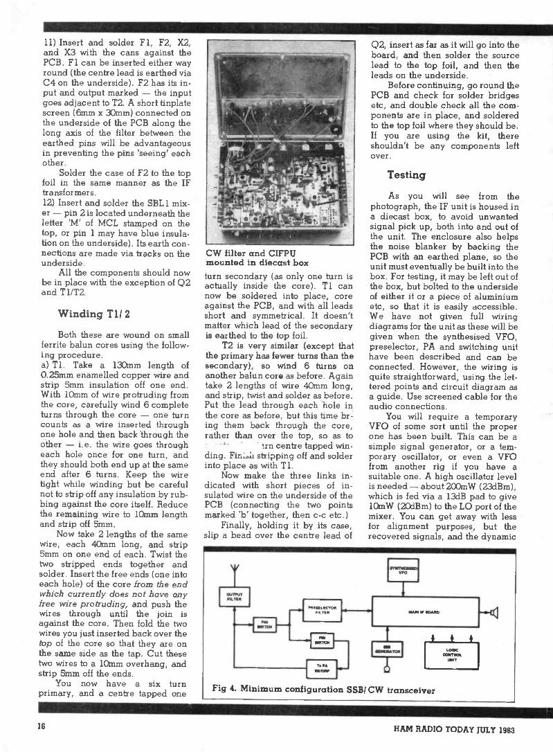
Winding T1/ 2
Both these are wound on smallferrite balun cores using the follow-ing procedure.a) T1. Take a 130mm length of0.25mm enamelled copper wire andstrip 5mm insulation off one end.With 10mm of wire protruding fromthe core, carefully wind 6 completeturns through the core - one turncounts as a wire inserted throughone hole and then back through theother - i.e. the wire goes througheach hole once for one turn, andthey should both end up at the sameend after 6 turns. Keep the wiretight while winding but be carefulnot to strip off any insulation by rub-bing against the core itself. Reducethe remaining wire to 10mm lengthand strip off 5mm.
Now take 2 lengths of the samewire, each 40mm long, and strip5mm on one end of each. Twist thetwo stripped ends together andsolder. Insert the free ends (one intoeach hole) of the core from the endwhich currently does not have anyfree wire protruding, and push thewires through until the join isagainst the core. Then fold the twowires you just inserted back over thetop of the core so that they are onthe same side as the tap. Cut thesetwo wires to a 10mm overhang, andstrip 5mm off the ends.
You now have a six turnprimary, and a centre tapped one
CW filter and CIFPUmounted in diecast boxturn secondary (as only one turn isactually inside the core). T1 cannow be soldered into place, coreagainst the PCB, and with all leadsshort and symmetrical. It doesn'tmatter which lead of the secondaryis earthed to the top foil.
T2 is very similar (except thatthe primary has fewer turns than thesecondary), so wind 6 turns onanother balun core as before. Againtake 2 lengths of wire 40mm long,and strip, twist and solder as before.Put the lead through each hole inthe core as before, but this time br-ing them back through the core,rather than over the top, so as to
'in centre tapped win-ding. Fini.li stripping off and solderinto place as with Ti.
Now make the three links in-dicated with short pieces of in-sulated wire on the underside of thePCB (connecting the two pointsmarked 'b' together, then c -c etc.)
Finally, holding it by its case,slip a bead over the centre lead of
Q2, insert as far as it will go into theboard, and then solder the sourcelead to the top foil, and then theleads on the underside.
Before continuing, go round thePCB and check for solder bridgesetc, and double check all the com-ponents are in place, and solderedto the top foil where they should be.If you are using the kit, thereshouldn't be any components leftover.
Testing
As you will see from thephotograph, the IF unit is housed ina diecast box, to avoid unwantedsignal pick up, both into and out ofthe unit. The enclosure also helpsthe noise blanker by backing thePCB with an earthed plane, so theunit must eventually be built into thebox. For testing, it may be left out ofthe box, but bolted to the undersideof either it or a piece of aluminiumetc, so that it is easily accessible.We have not given full wiringdiagrams for the unit as these will begiven when the synthesised VFO,preselector, PA and switching unithave been described and can beconnected. However, the wiring isquite straightforward, using the let-tered points and circuit diagram asa guide. Use screened cable for theaudio connections.
You will require a temporaryVFO of some sort until the properone has been built. This can be asimple signal generator, or a tem-porary oscillator, or even a VFOfrom another rig if you have asuitable one. A high oscillator levelis needed - about 200mW (23dBm),which is fed via a 13dB pad to give10mW (20dBm) to the LO port of themixer. You can get away with lessfor alignment purposes, but therecovered signals, and the dynamic
Fig 4. Minimum configuration SSB/ CW transceiver
16 HAM RADIO TODAY JULY 1983
SCHOTTKYRING MIXER
OM I
METERAMP013
ROOFINGFILTER
;PT I. IFT2
T. CARRIEROSCILLATOR
010. 011
AOCDELAY
DIREM NA TOE
IC2.D70111
IFPRE -AMP
01
DELAYNOIRE
BLANKERCRY TAL
IL ERNOTCHFILTER
FINALIF AEI
PRODUCTDETICT011
AFOUTPUT
IC1FILTER
f ISWITCH
02. 031. 02& MAIN Ii AMP FOB a a
NOISEBLANKER
CV, CB
H PULSERECTIFIER
os, os
STATICCRASHLIMITERat, co
MDETONE INACTION ICIV ONLY)
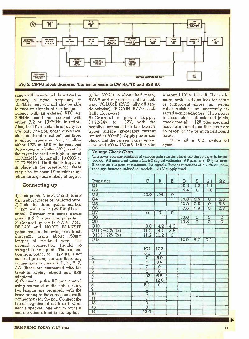
Fig 5. CIFPU block diagram. The basic mode is CW RX/TX and SSB RX
BFO012
range will be reduced. Injection fre-quency is signal frequency +10.7MHz, but you will also be ableto receive signals at the image fr-quency with an external VFO eg.3.5MHz could be received witheither 7.2 or 13.9MHz injection.Also, the IF as it stands is really forCW only (the SSB board gives swit-ched sideband selection), but thereis enough range on VC3 to alloweither USB or LSB to be receiveddepending on whether VC3 is set forthe crystal to oscillate high or low of10.7000MHz (nominally 10.6985 or10.7015MHz). Until the IF traps arein place on the preselector, theremay also be some IF breakthroughwhile testing (more likely at night).
Connecting up
1) Link points N & P, C (Sr B, E & Fusing short pieces of insulated wire.2) Link the three points marked'+ 12V' with the '+ 12V RX' (U) ter-minal. Connect the meter acrosspoints R (Sr Q, observing polarity.3) Connect up the IF GAIN, AGCDECAY and NOISE BLANKERpotentiometers following the circuitdiagram, using about 150mmlengths of insulated wire. Theground connection should gostraight to the top foil. The connec-tion from point I to + 12V RX is notmade at present, nor are there anyconnections to points K, L, M, Y, Z,AA (these are connected with thebreak-in keying circuit and SSBadaptors).4) Connect up the AF gain controlusing screened audio cable. Onlytwo lengths are required, with thebraid acting as the screen and earthconnections for the pot. Connect thebraids together at each end. Con-nect a speaker, one end to point Vand the other direct to the top foil.
5) Set VC2/3 to about half mesh,RV3,5 and 6 presets to about halfway, VOLUME (RV2) fully off (an-ticlockwise), IF GAIN (RV7) on full(fully clockwise).6) Connect a power supply( + 12-14v) to + 12V, with thenegative connected to the board'supper surface (preferably currentlimited to 200mA). Apply power andcheck that the current consumptionis around 100 to 160 mA. If it is a lot
is around 100 to 160 mA. If it is a lotmore, switch off and look for shortsor component errors (eg. wrongvalue resistors, or incorrectly in-serted semiconductors). If no poweris taken, check all soldered joints,check that all + 12V pins specifiedabove are linked and that there areno breaks in the print circuit boardtracks.
Once all is OK, switch offagain.
Voltage Check ChartThis gives average readings at various points in the circuit for the voltages to be ex-pected. All measured using a high -Z digital voltmeter. AF gain min, IF gain max,Blanker on but gain at minimum. No signals. Expect variations of 5-10% on thesereadings between individual models. 12.0V supply used.
Transistor CB E D S G 1 G2Q1 10.2 1.2 1.1Q2 5.4 0 .08Q3 12.0 .08 0Q4 10.8 0.6 0 5.6Q5 10.8 0.6 0 5.6Q6 7.6 0.8 0 0.8Q7 0 0 0Q8 10.8 0 0 0Q9 10.8 0 0 0Q10 8.8 4.2 4.0Q11 (+12V Tx) 11.2 4.1 3.8Q12 (+ 12V Tx) 11.2 11.2 0Q13 12.0 5.7 7.1
IC I IC21 6.1 02 0 6.03 0 5.94 0 05 0 06 02 6.57 0 12.08 5.1 09 010 011 012 013 014 12.0
HAM RADIO TODAY JULY 1983 17
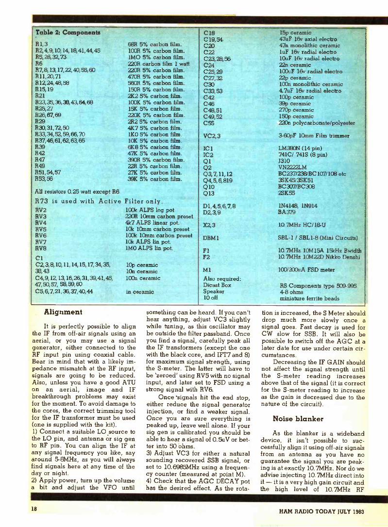
Table 2: Components C18C19,54
15p ceramic47uF 16v axial electro
R1,3 68R 5% carbon film. C20 47n monolithic ceramicR2,4,9, 10, 14, 18,41,44, 45 100R 5% carbon film. C22 luF 16v radial electroR5,28,32,73 1MO 5% carbon film. C23,2256 10uF 16v radial electroR6 2208 carbon film 1 watt C24 22n ceramicR7,8,13,17,22,40,55,60 L2UR 5% carbon film. C25,29 100uF 16v radial electroR11,20,71 470R 5% carbon film. C27,32 22p ceramicR12,24,48,58 560R 5% carbon film. C33 lOOn monolithic ceramicR15,19 1508 5% carbon film. 033,53 4.7uF 16v radial electroR21 2K2 5% carbon film. C42 100p ceramic823,35,36,38,43,64,68 1C0K 5% carbon film. C46 39p ceramicR25, 27 15K 5% carbon film. C48, 51 270p ceramicR26,67,69 L2OK 5% carbon film. C49, 52 150p ceramicR29 282 5% carbon film. C55 220n polycarbonate/polyesterR30,31,72,50 4K7 5% carbon film.833,34,52,59,66,70 1KO 5% carbon film. VC2,3 3-60pF 10mm Film trimmer837,46,61,62,63,65 10K 5% carbon film.R39 6K8 5% carbon film. IC I LM380N (14 pin)R42 47K 5% carbon film. 102 741C/ 741S (8 pin)R47 3908 5% carbon film. 01 J310R49 22R 5% carbon film. Q2 VN2972r M
BC237/238/BC107/103 etcR51,54,57 27K 5% carbon film. Q3, 7,11,12R53,56 39K 5% carbon film. Q4,5,6,819 3SK45/35K51
Q10 BC307/BC308All resistors 0.25 watt except R6 Q13 2SK55
R73 is used with Active Filter only.RV2 100k ALPS log pot
D1,4,5,6,7,8D2,3,9
1N4148, 1N914BA379
RV3 2208 10mm carbon presetRV4 4k7 ALPS linear pot. X2, 3 10.7MHz HC/18-URV5 10k 10mm carbon presetRV6 100k 10mm carbon preset DBM 1 SBL-1 / SBL 1-8 (Mini Circuits)RV7 10k ALPS lin pot.RV8 1MO ALPS lin pot. F1 10.7MHz 10M15A 15kHz BwidthC1 F2 10.7MHz 10M22D Nikko DenshiC2, 3,8,10, 11, 14, 15,17,34,35, 10p ceramic38,43 10n ceramic M1 100/200uA FSD meterC4,9,12,13, 16,26,31,39,41,45, 100n ceramic Also required:47,50,57, 58,59,60 Dicast Box RS Components type 509-995C5, 6,7,21,36,37,40,44 in ceramic Speaker
10 off4-8 ohmsminiature ferrite beads
Alignment
It is perfectly possible to alignthe IF from off -air signals using anaerial, or you may use a signalgenerator, either connected to theRF input pin using coaxial cable.Bear in mind that with a likely im-pedance mismatch at the RF input,signals are going to be reduced.Also, unless you have a good ATUon an aerial, image and IFbreakthrough problems may existfor the moment. To avoid damage tothe cores, the correct trimming toolfor the IF transformer must be used(one is supplied with the kit).1) Connect a suitable LO source tothe LO pin, and antenna or sig gento RF pin. You can align the IF atany signal frequency you like, sayaround 5-8MHz, as you will alwaysfind signals here at any time of theday or night.2) Apply power, turn up the volumea bit and adjust the VFO until
something can be heard. If you can'thear anything, adjust VC3 slightlywhile tuning, as this oscillator maybe outside the filter passband. Onceyou find a signal, carefully peak allthe IF transformers (except the onewith the black core, and IFT7 and 8)for maximum signal strength, usingthe S -meter. The latter will have tobe 'zeroed' using RV5 with no signalinput, and later set to FSD using astrong signal with RV6.
Once signals hit the end stop,either reduce the signal generatorinjection, or find a weaker signal.Once you are sure everything ispeaked up, leave well alone. If yoursig gen is calibrated you should beable to hear a signal of 0.5uV or bet-ter into 50 ohms.3) Adjust VC3 for either a naturalsounding recovered SSB signal, orset to 10.6985MHz using a frequen-cy counter (measured at point M).4) Check that the AGC DECAY pothas the desired effect. As the rota-
tion is increased, the S Meter shoulddrop much more slowly once asignal goes. Fast decay is used forCW slow for SSB. It will also bepossible to switch off the AGC at alater date for use under certain cir-cumstances.
Decreasing the IF GAIN shouldnot affect the signal strength untilthe S -meter reading increasesabove that of the signal (it is correctfor the S -meter reading to increaseas the gain is decreased due to thenature of the circuit).
Noise blanker
As the blanker is a widebanddevice, it isn't possible to suc-cessfully align it using off -air signalsfrom an antenna as you have noguarantee the signal you are peak-ing is at exactly 10. 7MHz. Nor do weadvise injecting 10.7MHz direct intoit - it is a very high gain circuit andthe high level of 10.7MHz RF
18 HAM RADIO TODAY JULY 1983
resulting tends to have a disastrouseffect on the rest of the circuit!
By far the best way is to use asignal generator as a signal source,or any oscillator capable of giving asingle signal within the currentreceive coverage for the VFO beingused. If you have a scope, all thebetter.1) Temporarily connect a Incapacitor from point Y to earth (tosimulate the effect of the In feed -through capacitor that will connectto this point later.)2) Connect point J to + 12V, andturn the BLANKER LEVEL controlfully off (anticlockwise - wiper atOV). using a suitable single signalsource, locate the signal with theVFO. Then:
a) If a scope is available (set toDC coupling, 1V/cm) slowly ad-vance the blanker level until thescope reading starts to gonegative. Peak IFT7 and 8(reducing the blanker level ifnecessary) for best deflection.Once aligned, peak deflection(maximum blanking) should bearound 4-5 volts.b) If no scope is available, ad-vance the blanker level until youhear the audio from the receiverstarting to be cut off. Then adjustthe cores of IFT7 and 8 whilebacking off the BLANKER LEVELif needed, until the blanking ac-tion starts at as low a level aspossible. Turning the control ful-ly clockwise should turn theaudio off completely well beforethe stop is reached, if the signalbeing used is fairly strong.
Using the blanker
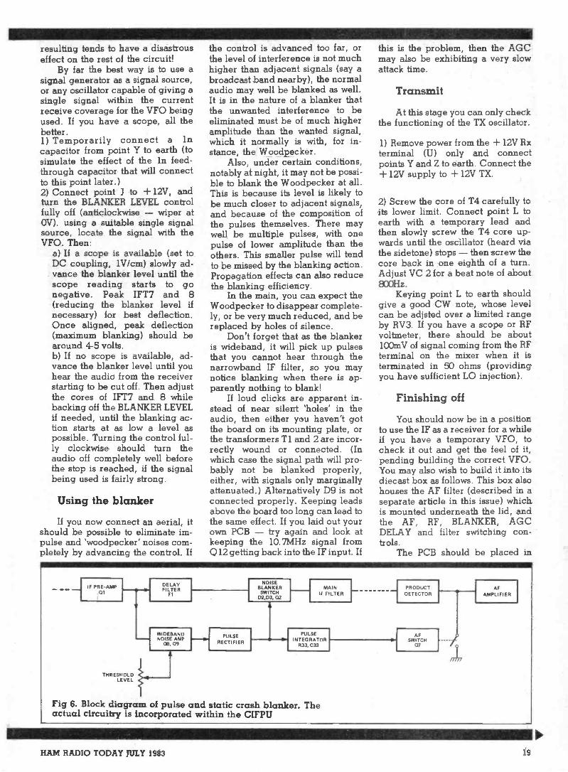
If youshould bepulse andpletely by
now connect an aerial, itpossible to eliminate im-'woodpecker' noises com-advancing the control. If
the control is advanced too far, orthe level of interference is not muchhigher than adjacent signals (say abroadcast band nearby), the normalaudio may well be blanked as well.It is in the nature of a blanker thatthe unwanted interference to beeliminated must be of much higheramplitude than the wanted signal,which it normally is with, for in-stance, the Woodpecker.
Also, under certain conditions,notably at night, it may not be possi-ble to blank the Woodpecker at all.This is because its level is likely tobe much closer to adjacent signals,and because of the composition ofthe pulses themselves. There maywell be multiple pulses, with onepulse of lower amplitude than theothers. This smaller pulse will tendto be missed by the blanking action.Propagation effects can also reducethe blanking efficiency.
In the main, you can expect theWoodpecker to disappear complete-ly, or be very much reduced, and bereplaced by holes of silence.
Don't forget that as the blankeris wideband, it will pick up pulsesthat you cannot hear through thenarrowband IF filter, so you maynotice blanking when there is ap-parently nothing to blank!
If loud clicks are apparent in-stead of near silent 'holes' in theaudio, then either you haven't gotthe board on its mounting plate, orthe transformers T1 and 2 are incor-rectly wound or connected. (Inwhich case the signal path will pro-bably not be blanked properly,either, with signals only marginallyattenuated.) Alternatively D9 is notconnected properly. Keeping leadsabove the board too long can lead tothe same effect. If you laid out yourown PCB - try again and look atkeeping the 10.7MHz signal fromQ12 getting back into the IF input. If
this is the problem, then the AGCmay also be exhibiting a very slowattack time.
Transmit
At this stage you can only checkthe functioning of the TX oscillator.
1) Remove power from the + 12V Rxterminal (U) only and connectpoints Y and Z to earth. Connect the+ 12V supply to + 12V TX.
2) Screw the core of T4 carefully toits lower limit. Connect point L toearth with a temporary lead andthen slowly screw the T4 core up-wards until the oscillator (heard viathe sidetone) stops - then screw thecore back in one eighth of a turn.Adjust VC 2 for a beat note of about800Hz.
Keying point L to earth shouldgive a good CW note, whose levelcan be adjsted over a limited rangeby RV3. If you have a scope or RFvoltmeter, there should be about100mV of signal coming from the RFterminal on the mixer when it isterminated in 50 ohms (providingyou have sufficient LO injection).
Finishing off
You should now be in a positionto use the IF as a receiver for a whileif you have a temporary VFO, tocheck it out and get the feel of it,pending building the correct VFO.You may also wish to build it into itsdiecast box as follows. This box alsohouses the AF filter (described in aseparate article in this issue) whichis mounted underneath the lid, andthe AF, RF, BLANKER, AGCDELAY and filter switching con-trols.
The PCB should be placed in
IF PRE -AMP01
THRESHOLDLEVEL
DELAYFILTER
Fl
WIDEBANDNOISE AMP
08, C/9
NOISEBLANKER
SWITCHD2,03, Ca
MAINIF FILTER
Fig 6. Block diagram of pulse and static crash blanker. Theactual circuitry is incorporated within the CIFPU
HAM RADIO TODAY JULY 1983 19

Getting rid of the woodpecker. An actual scope shot of blanking signal at Q2
the bottom of the box, and the holepositions marked through, beforedrilling four 3mm holes. The boardmounts on four 6mm spacer pillars(or three EiBA nuts) to space it frombottom of the box, using 6BA bolts.
The four controls mount on thefront of the box, and eventuallyagainst the front panel of the rig.The box specified has a pillar whichwill have to be filed or ground off toallow the central control to be fitted.The four holes are drilled with31mm spacing between them, 13mmbelow the box top.
You will also need to drill aseries of holes around the outsideedges of the box, 13mm from the topedge and of a diameter to suit the1000pF feedthrough capacitors forthe following connection points:+ 12V, + 12V RX, 12V TX, Z, Y,AA, J, L, N, P, Q and R. If you can'tfind any screw -in feedthroughs, youcan use solder -in ones by usingstrips of tinplate or PCB as a carrier,bolted to the inside of the case.Alternatively you can use insulatedfeedthrough terminals with Inceramics across them fordecoupling.
The speaker connections frompoint V should be taken to a feed -through using screened cable, with
the braid earthed at the feedthroughvia a solder tag. The output thengoes to the speaker cable, which hasone lead earthed by another soldertag on the outside of the box. Allconnections should be as near to thepoints they go to as possible, and asuitable legend written at each onthe outside of the box. A double rowof feedthroughs was used on therighthand side of the box illustrated,lOmm below the first row to avoidcrowding.
Coaxial inputs
In addition, coaxial sockets arerequired, one for the LO, and onefor RF - use Belling Lee, miniatureBelling Lee, BNC or whatever youprefer, located above the terminalpins they connect to and wired tothe PCB using miniature coaxialcable.
If you are going to be using theIF notch filter, two more coaxialsockets will be needed, with a tem-porary coaxial link between them,again connected to the PCB usingcoaxial cable (points B and C).
For those who will be adding theSSB adaptor, another pair of coaxialsockets are needed, going to pointsM and K. Thus there will be six
sockets required if the complete unitis being built. The photograph willshow the approximate locations foreach if you follow the wiring (fulldetails in a later part).
Audio filter
If you are going to use the audiofilter, this mounts on the undersideof the lid, with the front edge of thePCB 26mm from the front of the lid(to clear the internal switch). Allconnections to it are made withscreened AF cable with both ends ofthe braid earthed. (If a 12 way 1 poleswitch is used, locked to the 8 posi-tions required, one of the spare tagscan be used as a braid anchorpoint.) The input of the filter (A)goes to point E, and the output (fromthe switch via point L on the filter)goes to point F (remove the link bet-ween E & F!). An additional IMOresistor (not shown on the circuitdiagram but R73) should be con-nected from the input of the filter(A) to earth. Power comes from+ 12V on the main PCB.
Next month: The IF Notch Filter andPreselector Filter modules.
20 HAM RADIO TODAY JULY 1983

Aerial Farmingat HF
By Malcolm Healey G3TNO
Many HF operators like to try out different homemade wire aerials. Thisarticle shows how six years of such trial and error led to a multiband system
that not only beats a half -wave dipole for low -angle DX working, butreduces the strength of European stations as well.
B C
Fig. 1 35ft supports available at author's house
Over a period of years the writer hasoperated on the HF bands from anumber of different locations. Itsoon became apparent that the mostimportant part of the station lay inthe aerial system. It is far better tospend a few hours and a pound ortwo on getting the radiating systemperforming well, rather than a fewhundred pounds on a big linearamplifier and using a lot of power intrying to counteract the short com-ings of a poor aerial system, notforgetting that with a good aerialyou get advantages on receive too!
It is hoped that this article maygive you food for thought in makingan aerial system which will workwell in your QTH. I have found thatan aerial system which works well atone site may, due to local effects,perform very differently at another.The differences are in some part dueto local effects such as soil conduc-tivity, local screening due to hills,
buildings and even trees.When carrying out aerial ex-
periments I always put a simple twoline entry in the log book, describ-ing the aerial system, includingdimensions, height, type of feed andnot the least important the earthingsystem if needed.
When planning new aerial askyourself a few questions:1) What band(s) do you wish it towork on?2) What space do you have?3) Are there any natural sky hooks(trees, buildings etc.)?4) At what times of day are you ableto operate? (It is no use putting amonster beam for say 80 metres fir-ing at the USA or Canada if you canonly get on the air at lunch times asband conditions would, in the main,be unsuitable to use such a device).5) Decide what would be sociallyacceptable at you QTH (yourneighbours may well not consider
your latest 6 element 20 metre beama thing of great beauty), especiallyin urban locations. Your family maywell be put right off your hobby,especially if their once friendlyneighbours stop being friendly "Cosher OM has gone mad, trying tocompete with the aerial farm atDaventry!"6) Consider any planning permis-sion you may need before buyingany aerials or towers etc. I havealways found my local planningdepartment to be very helpful withany queries. But ask first. We haveall seen the adverts of the unwise,"For sale, unused tower and beamsunable to get planning permission.Offers (Please! )"
Before putting up any aerials,make a plan of your garden in-cluding any natural help such astrees, buildings and don't forget thatthe TV aerial pole on the roof can bevery useful as a support as well.Mark in all dimensions, possiblefeeder runs etc. In my own case Iwished to work on all bands 160-10metres, and hoped for an aerial thatwould provide contacts with the ma-'ority of stations called.
AB
C
Note Dipoles spacedapprox l'apart by use of
light weight plastic spacersCentre lee. dipole
insulator
7511 twin feederto ATU
Fig. 2 Parallel dipoles
HAM RADIO TODAY JULY 1983 21
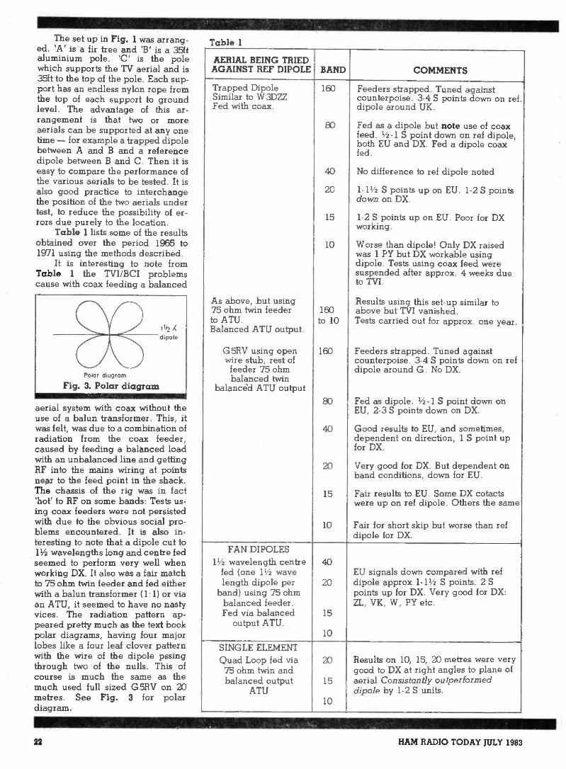
The set up in Fig. 1 was arrang-ed. 'A' is a fir tree and 'B' is a 35ftaluminium pole. 'C' is the polewhich supports the TV aerial and is35ft to the top of the pole. Each sup-port has an endless nylon rope fromthe top of each support to groundlevel. The advantage of this ar-rangement is that two or moreaerials can be supported at any onetime - for example a trapped dipolebetween A and B and a referencedipole between B and C. Then it iseasy to compare the performance ofthe various aerials to be tested. It isalso good practice to interchangethe position of the two aerials undertest, to reduce the possibility of er-rors due purely to the location.
Table 1 lists some of the resultsobtained over the period 1965 to1971 using the methods described.
It is interesting to note fromTable 1 the TVI/BCI problemscause with coax feeding a balanced
aerial system with coax without theuse of a balun transformer. This, itwas felt, was due to a combination ofradiation from the coax feeder,caused by feeding a balanced loadwith an unbalanced line and gettingRF into the mains wiring at pointsnear to the feed point in the shack.The chassis of the rig was in fact'hot' to RF on some bands: Tests us-ing coax feeders were not persistedwith due to the obvious social pro-blems encountered. It is also in-teresting to note that a dipole cut to11/2 wavelengths long and centre fedseemed to perform very well whenworking DX. It also was a fair matchto 75 ohm twin feeder and fed eitherwith a balun transformer (1: 1) or viaan ATU, it seemed to have no nastyvices. The radiation pattern ap-peared pretty much as the text bookpolar diagrams, having four majorlobes like a four leaf clover patternwith the wire of the dipole pssingthrough two of the nulls. This ofcourse is much the same as themuch used full sized G 5RV on 20metres. See Fig. 3 for polardiagram.
Table 1
AERIAL BEING TRIEDAGAINST REF DIPOLE BAND COMMENTS
Trapped Dipole 160 Feeders strapped. Tuned againstSimilar to W3DZZ counterpoise. 3-4 S points down on ref.Fed with coax. dipole around UK.
80 Fed as a dipole but note use of coaxfeed. 1/2-1 S point down on ref dipole,both EU and DX. Fed a dipole coaxfed.
40 No difference to ref dipole noted
20 1-11/2 S points up on EU. 1-2 S pointsdown on DX.
15 1-2 S points up on EU. Poor for DXworking.
10 Worse than dipole! Only DX raisedwas 1 PY but DX workable usingdipole. Tests using coax feed weresuspended after approx. 4 weeks dueto TVI.
As above, but using Results using this set-up similar to75 ohm twin feeder 160 above but TVI vanished.to ATU. to 10 Tests carried out for approx. one year.Balanced ATU output.
G5RV using open 160 Feeders strapped. Tuned againstwire stub, rest of counterpoise. 3-4 S points down on ref
feeder 75 ohmbalanced twin
balanced ATU output
dipole around G. No DX.
80 Fed as dipole. 1/2-1 S point down onEU, 2-3 S points down on DX.
40 Good results to EU, and sometimes,dependent on direction, 1 S point upfor DX.
20 Very good for DX. But dependent onband conditions, down for EU.
15 Fair results to EU. Some DX cotactswere up on ref dipole. Others the same
10 Fair for short skip but worse than refdipole for DX.
FAN DIPOLES11/2 wavelength centre 40
fed (one 11/2 wave EU signals down compared with reflength dipole per 20 dipole approx 1-11/2 S points. 2 S
band) using 75 ohm points up for DX. Very good for DX:balanced feeder. ZL, VK, W, PY etc.Fed via balanced
output ATU.15
10
SINGLE ELEMENTQuad Loop fed via 20 Results on 10, 15, 20 metres were very75 ohm twin and good to DX at right angles to plane ofbalanced output 15 aerial Consistantly outperformed
ATU dipole by 1-2 S units.10
22 HAM RADIO TODAY JULY 1983
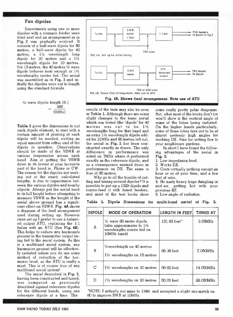
Fan dipolesExperiments using one or more
dipoles with a common feeder weretried next and an arrangement as inFig. 2 was gradually evolved. Itconsists of a half -wave dipole for 80metres, a half -wave dipole for 40metres, a 11/2 wavelength longdipole for 20 metres and a 11/2
wavelength dipole for 10 metres.For 15 metres, the 40 metres 1/2 wavedipole behaves near enough as 11/2wavelengths centre fed. The aerialwas assembled as in Fig. 2 and in-itially the dipoles were cut to lengthusing the standard formula
1/2 -wave dipole length (ft.)468
f(MHz)
Table 2 gives the dimensions to cuteach dipole element, to start with acertain amount of pruning of eachdipole will be needed, cutting anequal amount from either end of thedipole in question. Observationsshould be made of the VSWR atvarious frequencies across eachband. Aim at getting the VSWRdown to its lowest at your favouritepart of the band ie. Phone or CW.The reason for the dipoles not work-ing out at the exact, calculatedlengths, is due to capacitance bet-ween the various dipoles and nearbyobjects. Always put the aerial backto its full height before attempting tomeasure VSWR as the height of theaerial above ground has a signifi-cant effect on VSWR. Fig. 4A showsa diagram of the feed arrangementused during setting up. Howeveronce set up I prefer to use a balanc-ed output ATU, replacing the 1:1balun with an ATU (See Fig. 4B).This helps to reduce any harmonicspresent in the transmitter output be-ing fed to the aerial system. As thisis a multiband aerial system, anyharmonics present will be effective-ly radiated unless you do use somemethod of reduction of the har-monic level, so the ATU is really amust. This is of course true of anymultiband aerial system!
The aerial described in Fig. 2,having been constructed and tuned,was compared as previouslydescribed against reference dipolesfor the different hands, using onereference dipole at a time. The
Tx /Rx
SWRmeter
175111
FIG. 4A. Set up for initial tuning
Tx/RxSWR.meter
7511 coax
1:1 bal
ATU
balancedoutput
7511. or 5011 coaxFIG 48 Shows final arrangement, Note use of ATU
7511 'feedersto dipole in fig 2
7511 feederto dipole
Fig. 4B. Shows final arrangement. Note use of ATU
results of the tests may also be seenin Table 1. Although there are someslight changes to the basic aerialwhich was tested (the 'dipole' for 40metres was cut to be 11/2
wavelengths long for that band andan extra 11/2 wavelength dipole add-ed for 21MHz and 80 metres left out,the aerial in Fig. 2 has been con-structed exactly as drawn. The onlydifference in performance wasnoted on 7MHz where it performedexactly as the reference dipole, andas a consequence seemed down inperformance on DX. The same istrue of 80 metres.
Why go to all the trouble of cut-ting and tuning several dipoles? It ispossible to put up a 132ft dipole andcentre -feed it with tuned feeders,and most of the text books show
some really pretty polar diagrams.But, what most of the books don't (orwon't) show is the vertical angle ofsome of the lobes being radiated.On the higher hands particularly,some of these lobes turn out to be atalmost uselessly high angles forworking DX. Fine for setting fire toyour neighbours gardens.
In short I have found the follow-ing advantages of the aerial inFig. 2.1. Low impedance feed.2. Works DX.3. Costs virtually nothing except anhour or so of your time, and a fewfeet of wire.4. No nasty heavy traps dangling inmid-air, getting hot with yourprecious RF.5. Low angle of radiation.
Table 2 Dipole Dimensions for multi -band aerial of Fig. 2.
DIPOLE MODE OF OPERATION LENGTH IN FEET TUNED AT
A
1/2 wave 80 metre dipole(also approximates to 11/2wavelengths centre fed on10MHz band)
131.83 feet* 3.55MHz
B
1/2 wavelength on 40 metres
11/2 wavelengths on 15 metres66.38 feet 7.050MHz
C 11/2 wavelengths on 20 metres 99.92 feet 14.050MHz
D 11/2 wavelengths on 10 metres 50.05 feet 28. 050MHz
*NOTE: I actually cut mine to 134ft. and accepted a slight mis-match on80 to improve SWR at 10MHz.
HAM RADIO TODAY JULY 1983 23

NEWCOMER'SGetting a firstrig for HFSeveral people have asked how best toget a start on HF, especially wishing toknow what rig to go for. Advising whatequipment to buy is akin to advisingwhat car to purchase, a task which is tiedup with personal preference. But thereare some basic guidelines. It is much thesame with radio equipment - you canprobably find a dozen rigs which meetyour main needs, but in the end, the pur-chase may well depend on factors suchas appearance and plain 'gut' feel. Thisis quite normal for humans, buteverything that glisters is not gold!
You will have to battle against therecommendations of the various dealersand the advertisements, trying to decidewhether the features offered are whatyou require, ignoring the dolly birdswhich seem to be popping up much asthey do in car adverts.
TX/ RX or RX only?
Your first decision is likely to be in-fluenced by the depth of your pocket, orthe generosity of your bank manager,and with very little available new forunder £400 (except one semi -kit designat under £300) you may fell obliged to gofor something in the secondhandmarket. I would suggest that there isanother decision to make - do you in-itially need a transceiver, especially ifyou are to embark onto HF without anyexperience of it whatsoever?
In one of these past columns, I didmention that the act of initiation into thehobby is no longer by a period ofgeneral short wave listening, duringwhich you pick up all the operatingjargon, band characteristics, etc. Nowit's more often than not via CB, with awish to expand your horizons in morethan one sense. There are also those whohave a professional background in elec-tronics, but still have no basic amateurradio experience. Whatever route youtake, the day-to-day operatingknowledge can only be gained by ex-perience - no amount of reading, norPhD can replace this.
It's a bit like the driving test - fewwould suggest that at the moment youhave passed your driving test, howeverwell, you are fully equipped to drive acar. What I am leading up to is to sug-gest that you buy a receiver only, or if
you do want a transceiver, discard themicrophone for a while and control theurge to get on the air. This will give youthe opportunity to listen, and gain abasic knowledge of what goes on in theworld of HF, where things are rather dif-ferent to the world of VHF FM. You won'tnecessarily have to flog the RX after-wards, especially if it is a generalcoverage type (ie it covers say 500kHz-30Mhz, rather than just the amateurbands). Such a receiver can be valuablein later years.
Take your timeWhatever you do, take time before
parting with your hard-earned cash.There are many rigs to choose from, in-cluding a vast number of second-handones. Ask around, look at as manymagazine reviews as you can (reviewersshould be fairly impartial) and try to getyour hands on as many as possible. Ifyou ask people what they would recom-mend, bear in mind that personal opi-nions will always creep in - after aboutthe tenth request you should be getting aidea whether any particular peice ofequipment is getting a lot of mention(good or bad).
I will make no attempt at recommen-ding particular models myself - I'll justsay that there are plenty of very goodrigs to be found on the s/h market for£100- 200. Some may be up to 20 yearsold, but will still transmit and perfectlyadequately, which is the most importantthing. Yaesu and KW both made earlymodels which will conduct themselveswith perfect dignity today. Save yourpennies for the LED's, PBT, VBT,memories etc., until the time comeswhen you can appreciate them anddecide whether you actually need them.Frank and I are both of the opinion thateventually there will be a revolt, againstthe mass produced, high price 'bells andwhistles' commerical gear in favour ofsimpler, cheaper gear which you mightstand a chance of maintaining yourself.
There are still a number of good'separates' (ie, independent transmittersand receivers) around, of which somecan transceive if required. As a matter ofinterest 'transceive' is a modernphenomenon tied in with the advent ofSSB and co -channel working. Withseparates, if you wanted to work co -channel, you find the station you wantedon the receiver, then 'net' the separatetransmitter onto the frequency for zero -
beat using a low power transmit mode. Ittakes slightly more time, and is a positivedisadvantage during contests, but other-wise perfectly OK for run of the mill con-tacts.
Evaluating rig
You will have to judge a s/h piece ofgear mainly by a short on -the -air test,and this is essential - I doubt you wouldbuy a car without a test drive. There maybe something you cannot live with, andeven if you positively dislike a rig, theremay be a couple of good points you canbear in mind in the future. The receiveside is likely to be the main thing asthere is little you can gain from transmit-ting except for audio quality reports.One tip - if the chap you are buyingfrom has to look up in the manual beforetuning it, or takes a long time to do so (ordoesn't look as though he knows whathe's doing) start asking why he doesn'tuse the rig much! There may be someperfectly valid reason, on the otherhand, he may be concealing somethingnasty. Most private sales are usually ge-nuine, with the ever present urge toupgrade being a factor, and a lot of peo-ple can't help telling you the odd foibleabout the rig.
A few points to look for are stabilityof the VFO (leave it listening to a contactwhile you are talking, and see if it stayson frequency). Also sensitivity (difficultto judge without a comparison - trylistening for electrical interference onthe lower frequency bands, if it is absenteither there is a good blanker, or the rigis insensitive). Strong signal handling isanother thing to check (try listening on40m after dark or amateur CW stations.Can you only make out a mass of noiseand rubbish?).
Controls
Are the controls arranged in a con-venient way for you, bearing in mindthat you will be tuning around for longperiods. Would you prefer a tuningknob that can be spun rapidly, ratherthan have to crank the thing continually?If you feel you may become a CW ad-dict, then is the IF selectivity adequate,or can extra filters be added? (If so, atwhat cost?) Do you need a digital display(unlikely) or is an analogue version ade-quate? There are dozens of other con-siderations - try talking to fellow club
24 HAM RADIO TODAY JULY 1983

FORUBy Tony Bailey G3WPO
members to get a feel for what youshould look out for.
Power
If you're thinking of buying atransceiver, consider whether you ac-tually need high power. There arekasically two power levels with com-merical transceivers - lOW output or100-150W output. Remember that it isn'tthe PA that gets the signals to the otherstation, it is the aerial. A few poundsspent improving it is a much better in-vestment than a few extra Watts. Also, ifyou can't hear them you can't work them!There is no doubt that low power (QRP)operation (although 10 Watts is a bithigh for QRP) is more demanding inoperator expertise than high power(QR0) and you will have rather moredifficulty in working DX using 10W to asimple aerial, than with full legal powerto a 3 element beam, but which will giveyou the greater satisfaction? I wouldsuggest that the expertise gained undermore difficult conditions will stand youin good stead in years to come.
Buying from a dealer
If you buy a new rig, or evensecondhand via a dealer, one point tobear in mind is servicing. One of thereasons why some dealers are cheaperthan others is that they cannot providefull servicing facilities. Any sensibledealer will include an amount to coverpossible maintenance in his price andsomething towards getting hold of all thetest equipment needed to servicemodern equipment. He also has to carrya stock of spares for each rig if he is go-ing to do the job properly. So althoughyou pay more initially, you have the ad-vantage that if something goes wrong,the chances are that it can be put rightquicly, without waiting for the rig to gooff to a service centre, or for spares toarrive from overseas.
Buying secondhand
The dictate Caveat Emp tor or'Buyer Beware' is very much to the forein the secondhand market. Hence thereason for suggesting that you get yourhands on the rig for a while before buy-ing. Most amateurs are honest when ask-ed about any problems with the rig, butif you have doubts then consider
whether you should buy. If you are mis-led, then you do have recourse in law,but it can be a long job and may not beworth pursuing.
Home construction
You can of course build all or someof your equipment yourself. I always ad-mire anyone who can say during a con-tact that his equipment is home built,especially if his signal is first class. It is asatisfying experience to build your ownand get it working, even if you didn'tdesign it. At the end you will have learn-ed a lot, and probably be keen to moveonto something more complicated. I
doubt that you would want to reproduceone of the black boxes on the market, asthe thing with home brew gear is thatyou can design in the features you want,not what the manufacturer thinks youwant. The cash angle looks different ofcourse, and it is possible to get on HFCW for under £10, even under £5 if youwant. You can certainly build somethingdecent for f.,504.1C0. Most magazines,including this one, carry designs fortransmitters/receivers and a browsethrough past issues (you can beg or bor-row copies of most magazines from otheramateurs or get back copies from thepublishers in most instances) should pro-vide inspiration. Check that you can getall the parts before you start though -some of the older designs contain com-ponents which may be difficult toreplace. A case in point is the LM373multimode IF chip which was used in avariety of designs, but is now obsoleteand cannot be replaced without majorcircuit changes.
The shack
All of us have to operate from -somewhere, be it the living room,bedroom, cupboard under the stairs, ora purpose built/adapted room. The com-plexity and facilities required will de-pend on your interests. If you are a non -constructing, single -band VHF operatorthen very little space will be required,and your ancillary equipment should bereasonably limited. The multi -bandoperator with several rigs, tuning unitsetc will need more space, and if you con-struct as well then even more must beallocated if possible (XYL allowing etc).The shack should be designed foroperator comfort, convenience and not
the least safety.Taking the last point first, whatever
you operate will almost certainly needthe mains supply, either direct to the rig,or via a power supply unit. Make surethat everything is correctly fused asrecommended by the makers, and thateach piece of equipment has its ownoutlet - never use multiway adaptors.One sensible precaution is to have a pro-minent master switch, away from the im-mediate operating position, with its pur-pose clearly marked. In the unhappyevent that someone has to get the poweroff because you're attached to the mainssomehow, they won't have to grope forthe switch under the bench, and possiblyendanger their own lives in the process.
It's volts and jolts but'mils' that kills
Always respect any potentiallylethal voltage. Not so long ago, one ofmy locals was found dead after inadver -tantly electrocuting himself. It does hap-pen, and he was a man of long practicalexperience. The old adage of 'one handbehind the back' while working on liveequipment is still a good one.
If you do a lot of constructing, try toavoid using the operating position as thework bench. There is nothing worse thanscrabbling around under a pile of debrisfor the log, or a pencil, and you willscream when a piece of molten solderends up melting your rig's meter cover,or a piece of wire ends up inside the ven-tilation holes and does a nasty.
To strike a lighter note, there can behazards involved in using the shed at thebottom of the garden for the shack.Many years ago, one of our clubmembers was peering inside a piece ofequipment tyring to work out why thething kept drifting about in frequency.After a short period we noticed a slightmovement at one place, and after acloser look saw an insect emerging frominside a tubular ceramic capacitor in theVFO! So, if your rig drifts around, tryspraying it with insecticide rather thanElectrolube - it might do the trick!
Operator comfort
So many people ignore this, but it isone of most vital aspect of any shack.Like many things, a happy and comfor-table operator is a good operator (unlesshe also has the whisky bottle handy) sopay attention to layout.
The main TXJRX should be in themiddle, with everything else positionedaround it for maximum accessabilitydepending on use. The rig is generallyat bench level so that you don't have toreach to operate it and it should be plac-ed so that your arm doesn't tire after ex-tended periods of operation. It needs tobe far enough back on the bench to get alog book and notepad in front of it.
HAM RADIO TODAY JULY 1983 25

Buy'British] by
THE BANTEX RANGE
X All Aerials have Hinged WhipsX Mounts and Whips are Fully Interchangable* Whips aie Easily Removable
0 0
UDL UCL B5U
MD
MAG BTL
BC 4BA4
BGSP B5
BM /
PI
B4
089 c 088
091 095092
096
093
340/ 310/341440 330
i. \
350 351 B7
085 084
THE BANTEX ASCOT RANGE
* Choice of Straight, Hinged or Spring Bases* Variety of Gain Options -1/4 ; 1/2 ;5/8 and 7/8
* Option of Feeder Sections* Add -on Accessories o DEALER
MADE IN ENGLAND by BANTEX LONDON
26 HAM RADIO TODAY JULY 1983

VsingO Metres
By Tony Bailey G3WPO
A casual tune around during the day(and it is primarily a daytime band)may tend to give the beginner theimpression that there is little activity,or that the Europeans have a hold onthe band to the exclusion of otherareas. For those that know it, and howto use it, the band can be veryexciting, especially in its sometimesunpredictable behaviour.
During the past few years, theband has been at its best, with DXstations there for the taking using lowpower and simple aerials, often openfor much of the day to virtually all ofthe world at once. However, we arenow well on the downward path andit will not be long before the DX has tobe worked a lot harder for, althoughthis can still be done with low powersand simple antennas. As well as DX,Ten is an ideal band for local QSOsand much of the traffic passed on 2metres by the Class A licencees couldusefully be rerouted to 10 metres torelieve the VHF band of some of itscongestion on the FM channels.
Ionospheric propagation
There are a number of ways inwhich signals reach other parts of theworld. Most of these depend on thereflection of the signal by theIonosphere, or more correctly, one ofthe Ionospheric layers, of which thereare several.
The majority of real DX signalsare propagated by the F2 layer whichis the highest, with the heightdepending on the season, time of day,latitude and the state of the sunspotcycle. The other layers (D and E) areof no interest to us at 28MHz as theydo not reflect at this frequency.
The 10 metre bandappears to be viewed ina strange light by many
amateurs. There arethose who rate it as thebest of the HF bands,
and those who seem tothink of it as a ratherstrange band that isonly of use duringsunspot maxima
periods such as wehave just been through.
Usually around 120-260 miles abovethe Earth's surface, the F2 layer ispresent during both day and nightduring the peak of the sunspot cycle,but once the sun has set the reflectiveproperties rarely extend as far as28MHz. Hence the band is only 'open'during the hours of daylight, plusmaybe an hour of two into darknessduring the peak of the sunspot cycle.
The maximum ionisation leveloccurs at around mid -day for the mid-point of a given path during theWinter, and a bit later in the Summer.The earliest time at which a QSO canstart over any given East-West paththus depends on the position of theEarth relative to the Sun, and thestate of the Sun itself.
MUF
Whether or not 10 meters willsupport DX propagation via the F2
layer depends on this highestfrequency or MUF (Maximum UsableFrequency) at any given time - if theMUF is below 28MHz then signals arenot reflected and little propagationwill take place. At sunspot minimatimes, there is usually a two to threeyear period, mainly affecting East-West paths, when the MUF veryrarely gets to 28MHz, althoughcontacts with Africa are still possiblearound midday on a few days of themonth.
As one might expect, duringsunspot maxima periods theincidence of the MUF being above28MHz is high - it can get as high as70MHz, and it is during these timesthat the 6 metre band supportspropagation over the Atlantic,allowing cross band QSOs via 10metres with the States (and possiblydirect on 6 metres if we get full accessto the band).
The distance your signal willtravel via F2 propagation dependson the angle at which the signal hitsthe layer (dependent on the angle ofradiation of your antenna), and on thenumber of hops it makes between thelayer, the earth, and back again. Asingle hop signal can cover up to amaximum of about 2500 miles, with aminimum of about 1200 miles (thedistance will vary with ionosphericconditions, and the angle at whichthe signal is reflected, and thecritical angle for the frequency). Forcommunications at distances belowthis skip distance, other modes ofpropagation take over.
One interesting effect occurswhen the MUF is only just above28MHz. Under these conditions theF2 layer acts as an almost perfect RF
HAM RADIO TODAY JULY 1983 27

mirror and signals are readilyreflected at good strength. On theother hand, the areas covered at eachend of the path will be relativelysmall. This makes activity appearlow - especially if the local time atthe other end of the path correspondswith a period when activity below anyway.
This is one of the reasons why 10metres is famous for signals suddenlyappearing from an apparently deadband - one minute you can behearing nothing, and the nextworking a juicy piece of DX as youfind a path which coincides withsome activity. Low power can givesome surprising results under theseconditions, so a CQ on what appearsto be a dead band can be veryworthwhile.
Backscatter
You may have heard weak andwatery signals from other British andEuropean stations when they havebeen working into some other part ofthe world at the same time. Thephenomena is known as 'back -scatter', and occurs because when-ever the reflected signal hits theearth, a small part of it is scattered inall directions. When the F2 layer ishighly reflective, some of this scatterwill be reflected back to the sourcearea again, giving rise to these veryweak signals.
This mode of communicationworks best using CW and, if you are
using beams, you need to direct thistowards the DX location, not at thestation you are hearing, otherwisethe signal will almost certainly beweaker, if audible at all.
Sporadic -E
This is another term familiar tothe VHF operator, but equallyresponsible for propagation on 10metres. The distances involved areusually 400-1200 miles and themode is useful for working intoEurope. When you find the band fullof strong European stations, SporadicE short skip will be the reason.
The reflection occurs as a result ofthe formation of highly ionised cloudlayers at about the height of the Elayer (70 miles). They are random innature, and only last up to a fewhours, hence the name. They arethought to be caused by wind -shear,and are not directly related toSunspot activity, so they can happenat any time within the Solar cycle.
The Es season is May -August,with another small peak inmidwinter. During thr summer it canoccur at any time of the day, althoughearly evening and mid -morning arethe most likely times.
Due to the height of the clouds, asingle propagation hop has amaximum distance of around 1200miles. However, in the summer whenlarge areas of cloud may form,multiple hops via more then onecloud are achievable, extending the
communication range to 3000 milesor more.
The antennae and power neededfor Es are highly non -critical.Anything from a piece of wet string toa beam will work, and low power willoften be more then adequate.Received signal strengths canextremely strong, and, as thephenomena is short lived, in thesummer the band can often be full ofactivity one hour, and apparentlydead the next.
Troposphericpropagation
The 10 metre band is largelyignored for local communications,but is in fact capable of supportingthis well up to about 50-70 miles atany time of the day or night, and atany season. With the decrease in thelikelihood of DX QSOs during thecoming years, anything thatincreases the usage of the band willbe welcome.
Tropospheric propagation at28MHz is much like VHF, althoughnot so markedly affected by theweather. Signals will follow an airmass boundary such as the commontemperature inversion, where aboundary forms by one layer of airbeing cooler than another by virtue ofthe differing densities. The bestconditions occur in the evening asthings are cooling, and just beforesunrise. A reasonable aerial helps inkeeping the angle of radiation low,
28 HAM RADIO TODAY JULY 1983

but almost any antenna can be used.This mode is really a ground wavephenomenon, with the really stronglink between the two stations, with norefraction or reflection involved.
Meteor scatter
Meteor scatter propagation isnormally associated with 2 metrework, but occurs much more oftenand more intensely on 28MHz, with asingle small meteor capable ofionising an area 50 feet in diameterand over a mile long in the E layer.Signal strength increases of up to40dB are possible.
A single meteor trail is very shortlived (giving rise the 'pings' of signal)but if the earth encounters a shower ofthese objects, then almost continuouspropagation is possible at 28MHz.Being primarily a single hopphemomenon, the communicationsrange is limited to about 1300 miles,as for other E -layer reflections.
Aerials for Ten
While we would all like arotatable beam for 10 metres, thelocal council and the neighbours may
have other ideas. If you do want to trya beam, but don't fancy a full sizeversion, there are some small beamsavailable. The writer uses an HQ -1Minibea m (not the same as the G4MHtype) and can recommend this. It isn'tso clever on 20 metres (it covers 20,15, 10 & 6 metres) but does possessvery good directivity and gain on 10in a reasonably small space.
Simpler aerials can be used togood effect, and there are a largenumber of designs to be found. One ofthe simplest is the humble dipole,which even the smallest house shouldbe able to accomodate. Used ininverted-Vee fashion, it providesreasonably omnidirectionalcoverage with a fairly low angle ofradiation for those distant contacts,even with the apex only 0.2wavelengths above ground if you arereally restricted for height. Apossible unobtrusive mounting pointis over the roof of the house, using thechimney as the mounting and feedpoint. Most lofts will accomodate adipole should you be forced to keep itout of sight.
The equally humble 1/4 waveground plane works well on 10, and itis relatively easy to give it a good
earth to work against - rememberthat the feed impedance of a trueground plane with 90 degree radialsis 35 ohms, so there will be amismatch is using 50 ohms cable.This is unlikely to have any seriouseffect, but if it makes you happier, theimpedence can be raised bydropping the radials somewhat. Ifmounted in the clear, the angle ofradiation will be low, and as well asDX, it can be used for local workingproviding the other station is alsovertically polarised. The provision ofa good earth system (as the other halfof the antenna) also applies to anyvertical systems such as the trappedmultiband types.
Summary
10 metres if a band full ofsurprises and capable of supportingmany forms of propagation, despitethe poorer conditions now loomingup. Even with low power, plus a bit ofknowledge and some patience, DXwill still be there for the taking, sodon't neglect it. Also, the band isused for satellite downlinks - yetanother area of interest for manypeople.
METANTENNAS YAGIS to NBS
WHAT IS N.B.S.?In 1976 the U S National Bureau ofStandards published a report under theauthorship of Peter P Viezbicke detailingsome nine man-years of work under-taken in the optimisation of `fag' design
Investigation took place on the N B Santenna ranges at Sterling. Virginia andTable Mountain. Colorado into the interreleationship between director andreflector lengths spacing and diametersas well as the effect of the metalsupporting boom in order to achievemaximum possible forward gain
MET Iraqis have been designed andengineered within the strict specificationsof the N BS report
N.B.S. StandardCODE
70 cms
MODEL LENGTH GAIN COST(inc.VAT)
432/19T 19 Ele 2.2 m 14.2 dBd £33.90* 432/1 7X 17 Ele crossed 2.2 m 13.4 dBd £46.83
Gain Optimised 432/17T 17 Ele long 2.9 m 15 dBd £37.33
* 2 M
P.T.F.E. Insulated Gamma 144/77 7 Ele 1.6 m 10 dBd £19.99144/8T 8 Ele long 2.45 m 11 dBd £31.26* 144/14T 14 Ele 4.5 m 13 dBd £44.49
User Adjustable Matching 144/19T 19 Ele 6.57 m 14.2 dBd £53.22
* 144/6X 6 Ele crossed 2.5 m 10.2 dBd £37.86
N Socket Termination144/12X 12 Ele crossed 4.57 m 12.2 dBd C54.95
4M*Easy Assembly 70/3
70/53 Ele
5 Ele1.7 rri3.45 m
71 dBd9.2 dBd
£28.69£43.56*
Made in U.K.
*U.K. P&P on all above is 02.95144/GP 2 m Base Station Ground Plane C14 4 1 + P8P £1 30RG213 Coax and Andrew 1-fehai, Cable at Competelive Pricesplease telephone for details
ED VISATel: 0304 853021Enquiries from Overseas dealers welcome
METALFARE 12 Kingsdown Road.St Margarets-at-Clifte. DOVER. CT15 6AZ
HAM RADIO TODAY JULY 1983 29

A simple beamfor metre
FMTrying to get a good signal out froman urban area can be a problemespecially if you have limited space.
Vertical antennae seem to be theonly answer, but in addition tospraying RF in all directions theirsusceptability to manmadeinterference can be a problem.
Being the sort of person thatbelieves in "Why buy it when you canbuild it yourself?" it was decided asimple beam would be to someadvantage.
The main design is derived fromthe basic HB9CV. Both elementswere made from readily available CBdipoles (purchased by the author forjust £2.50 each).
The construction of the originalCB dipole is not strong enough towithstand horizontal mounting sosome modification is necessary. Fig.1 shows how the centrepiece isformed. Strip the plastic moulding ofall metal pieces and discard the topcover. To make the boom drill a pieceof thick wall aluminium tube in thecentre and fit it into the top of themoulded centrepiece. The cutouts inthe sides are made with a Stanleyknife and must be a close fit to thetube. Pass the 6mm bolt with thesolder tag through the centre, fit thewhole assembly to the boom andtighten up. The coaxial feed holemust face backwards.
After the two moulded centreshave been modified and fitted to theboom, fit the elements and hold themin place with self tapping screws,with the seams of the elements facinguppermost. Permanent fixing of theoverall length is made after finaladjustment.
Gamma match
The gamma match is made from astrip of aluminium 8mm wide by
By M Hadley G4JXX
1.5mm thick shaped into thedimensions shown in Fig. 2. If
necessary two shorter pieces can bejoined where the gamma matchcrosses the boom. Fix the corners ofthe gamma match to the mouldedcentrepieces using two M3 screws,the front screw having a solder tag on
the inside. Mix epoxy putty and formit between the boom and gammamatch to produce an insulating andsecuring block in the centre. Becareful to keep the 10mm distancebetween the gamma match, andboom and elements. Using selftapping screws, drill and fix the endsof the gamma match onto the frontdriven and rear reflector elements.
Strip the coaxial cable at the endand push it through the hole in thefront driven dipole centre. Solder thebraid to the solder tag and connect atemporary 100pF variable capacitorbetween the coax centre conductorand the solder tag on the M3 screw.
To match the antenna to thetransmitter, set the tuning capacitorto approximately half mesh and thedipole elements to the dimensionsshown in Fig. 2. Apply a smallamount of RF and check the SWR.With the transmitter off adjust thecapacitor then check the SWR again.Repeat the adjustments untilminimum SWR is obtained. Fine
Original dipole centre
M6 x 70 mm bolt
Boom
Solder tag
dEiCoaxial teed holeon front only
Aluminium tube 20mm oldx 300mm long x 13-5mm bore
Coaxial cable500 or 7211
Fig. 1 Showing modified dipolecentrepiece
v -
-M3 screw, nut and solder tagon inside
Gamma match
30 HAM RADIO TODAY JULY 1983

adjustment for resonance can bemade by altering the length ofelements 5mm at a time, butremember, adjustments to the frontdirector length involve equaladjustment to the rear reflector
length. Resonance should be fairlybroad centreing at around 29.5 MI-lz.
When final adjustment iscomplete lower the antenna and fixthe elements permanently with selftapping screws. Remove the tuning
Fig. 2 Aerial dimensions
12 40mm
1000mm 1000mm
4400mm
4980mm
Front driven element length4400mmRear reflector element length4980mmGamma match feed point1000mm from boomElement spacing 1240mm
Boom 25 mm 0/ D x 1350 length(aluminium)Gamma match8mm X 1.5mm X 3265mm(aluminium)Distance between gamma matchand elements lOmm
capacitor and replace it with a fixedcapacitor of the same value as theminimum SWR setting of the tuningcapacitor. If capacitance measuringequipment is not available it may benecessary to estimate the value fromthe adjusted position of the tuningcapacitor. In the author's case thiswas achieved with 60pF. A 100 voltworking capacitor is more thanadequate for powers up to 10 watts.
Fill the moulded dipole centreswith epoxy putty paying closeattention to sealing around thecoaxial cable entry. When it has set,seal all joints and screws with clearvarnish to prevent corrosion. Run thecoaxial cable underneath the boomand lead it away down the supportingpole.
Performance of this simpleantenna far exceeds that of a verticaland in the author's case manyJapanese, North American andSoviet stations have been workedwith just 5 watts of FM.
Although no originally is claimedfor the design, the final dimensionswere obtained through trial anderror. The simplicity of the designdoes allow further experimentation.
1'."1 0.4.10 ?I.. VD 4, , .....L10.1"... r.V ,..111,,,,..m....1...
IT'S THE WINNER!FOR AMATEUR RADIO
The Sussex Mobile RallySUNDAY 17th JULY
10.30 am - 5.00 pmBRIGHTON RACEGROUND
Racehill, Brighton, E. SussexENTRANCE £1
(UNDER 14 & DISABLED FREE)Free parking for over 4,000 carsover 20,000 sq.ft. exhibition area
under coverMany attractions for the whole family
and the usual trade standsADVANCE TICKETS AVAILABLE
At 80p on receipt of a S.A.E.from Miss W. Firmager, Flat 2,23 Chatham Place, Brighton
wescom IFACTORY APPOINTED YAESU MUSEN MAIN DEALER
FT980 Full RangeFT77 Full RangeFT101ZD, Mk. 3 (real
bargain)FT230/730FT480/780FT290/790
All Accessories
Frequency Counters byYaesu
Let your Spares andService problemsbecome ours.
625 Line FSTV
BEARCAT Main Dealer
TONE Equipment
Self-support TOWERS
E.I.R.P.B.'s
TAMAYA
ROYAL
MASCOT PowerSupplies
CAR TELEPHONES
WESTERN COMMUNICATIONS (GALWAY) LTD.Unit 1, I.D.A. Cluster Development,Tuam Road,Galway, IRELAND
Phone: (091) 65166/65208U.K./N.1.100091 65166/65208International Dial -'n1.13531/19)/65166/65208
Telex: 28933 MHTC El
HAM RADIO TODAY JULY 1983 31

Value forMoney?
When contemplating the purchase of new amateur bandtransmitting equipment most operators do take the powerrating into consideration - but what do all the figuresmean? Which rig is the most powerful? "200W" or "100
watts output"? Are the printed figures there to enlightenyour mind, or lighten your pocket? Whatever the inten-tions, the net result is confusion, and I honestly doubt ifsome makers even know what the figures used in their
specifications are supposed to mean!
by Harry Leeming G3LLL
Ham radio equipment power levelsin the UK have for many years beenstipulated on the basis of DC inputpower to the final amplifier. Onmost amateur bands the maximumallowed was 150 watts input, and soif the final amplifier was a valve andwas supplied with 1000 volts, themaximum current it could legally berun at would be 150 milliamps (P =V x I = 100) x 150/1000 = 150watts). This is not really a fullysatisfactory way of rating a radiotransmitter, as strength of signal isdependent upon the output powerand not its input power. In the1920s, however, when the regula-tions were drawn up, the measure-ment of input power was probablythe only practical way to legislateamateur power levels, as few hams(or Post Office inspectors for thatmatter) had any simple method ofaccurately measuring radio fre-quency power. Technology does ad-vance rather faster than officialdom(they have only just taken thereference to spark transmitters outof the licence!), so whilst sinceWorld War II there has been noneed to retain rather archaicmethods of measurement, the UK,and many ether countries untilrecently have still based theiramateur licence conditions on DCinput power.
The latest UK licence write up(or 'cockup' dependent on yourpoint of view) does regulate powerexpressed in decibels above onewatt 'dBW'. How this can logicallybe enforced when commercialpower meters are scaled instraightforward watts and the RAEsyllabus has never previously re-quired a knowledge of dBs is one oflife's mysteries. (Perhaps the guy atthe Home Office who has neverheard of front end or masthead pre -amp overload and thinks 934MHzwill cause less TVI than 200MHzdreamed this one up as well.) Inreality the new licence is a straighttranslation of the old one into 'dBWOutput' , allowing for normal effi-ciency in the PA stage.
Input power measurements havethe advantage of simplicity whereAM or CW transmitters are con-cerned, but caused a problem uponthe advent of SSB. A single side -band transmitter running in classAB1 or B has an input power whichis controlled by the loudness of thespeech with which it is beingmodulated. The. DC input power,therefore, is continuously changingthousands of times per second, andthe power amplifier current metercan only give an average input cur-rent reading dependent upon thepeak -to -trough ratio of the
operator's voice. Whilst this metercan give an experienced operator agood indication of the currentoperation of his equipment it cannotmeasure SSB input power.
The relationship of SSBand AM ratings
Fig. 1A and Fig. 1B respectivelyshow the familiar patter of an un-modulated, and then modulated100% by an audio tone. We willpresume that this is the output of a150 watt transmitter operating ataverage efficiency (usually 60 -70%) giving an output power of,say, 100 watts into a 100 ohm dummyload. The RMS voltage of the waveform shown at A will be 100 voltsand the current into the dummy load1 amp, RMS. In Fig. IB it will beseen that at audio peaks the voltageis doubled to 200 volts RMS. Whenthe voltage doubles, by Ohm's Lawso does the current; (hence the for-mula P ---- V 2/R.) 2 amps. at 200volts produces 400 watts RMS and soto use SSB terminology, 400 wattspeak envelope power (PEP) is pro-duced.
This shows the sense behind theHome Office ruling that SSB outputhas to be limited to 4(X) watts PEP onthe bands licensed for 150 watts DCinput power. 400 watts PEP is theoutput power that an average effi-ciency 150 watt fully modulated AMtransmitter might be expected togive when operated at 60 - 70% ef-ficiency.
The quoted figures?
Thirty years ago a '150 watt' AMtransmitter weighed several hun-dred weights, an FT101E 250W PEPtransmitter with built-in DC and ACpower supplies is portable - what'sthe difference? Technology mar-ches on, yes; miniaturisation, yes;no high level modulator, and now asolid state PSU, yes; but quite apartfrom all this the 150W inputtransmitter of the early 1950's had tooperate continuously on AM andproduced a 100W carrier and 400WPEP output power. The FTIOIE has amaximum PEP input power of 250Wand produces a PEP output power ofaround 150W. The FT101 like allmodern SSB ham rigs is not ratedcontinuously at 250W input (notethe 10 second maximum tune-upwarning in the instructions), and itis intended to be run at full power
32 HAM RADIO TODAY JULY 1983

A
100V RMS
Fig. 1A (141.4V PEAK)
B
IOR 282.8V PEAK AT PEAK OF AUDIO ONLY)
only on voice peaks. In the CWmode (quite apart from the UKlicence regulations) it is recom-mended that the power be reducedto below 180W input, and on AM,slow scan (or FM suitably adapted)80W input is about the limit. Due toa fall of efficiency at low power themaximum continuous carrier thatthe FT101E (or any similar modern250W SSB rig) can provide withoutoverheating is around 30W, so thatin real terms this modern 250W rigcan only deliver continuously onethird of the power a '150W' rig ofyesteryear could provide!
The figures in adverts
The object of advertising is to sell,and so with plenty of figures tochoose from we can hardly blamethe manufacturers for, in manycases, publicising the largest. (Youmay advertise your old car and state"brakes just re -aligned", but I doubtif you would add "clutch 8 years oldand badly worn". It's against the lawto deliberately falsify figures, butparticularly as purchasers of amateurradio transmitters can be expectedto be "duly qualified persons" thereis no obligation on the manufac-turer's part to explain them. Inputpower is a meaningless figure unlessthe efficiency of the power amplifierstage is known, and whilst gooddesign will usually produce an effi-ciency of at least 50% there is noguarantee that this is so, if the out-put is not quoted. (The biggest andfasted cars usually consume themost petrol, but however deep yourpocket I doubt if you would choosebrand Y simply because it usedmore petrol than brand X). Whenreading any type of specification theold legal maxim "let the buyerbeware" is good advice. And so withthis in mind let us have a look at afew figures quoted by makers and
retailers in advertisements in USand UK publications (no names butif the cap fits . . .!!!).
Solid state linearamplifier "200W PEP"No qualification of the figures is
given, hence we presume that this isSSB PEP DC input rating. It's solidstate so efficiency is probablyaround 45-55%; hence we guess thePEP output power at 100W, but theamplifier would probably have to berun at much reduced power on AMof FM to avoid overheating.
Another unit labelled "100Wsolid state linear amplifier". Furtherreading confirms that these peopleare talking about output power in allmodes and that unit will deliver100W continuously in the AM or FMmode, probably more than doublethe power in these modes of theabove "200W" amplifier!
VHF multimode transceiverlabelled "15-18W output". It's a pitythey didn't say whether it is a con-tinuous carrier RMS, or only PEP onSSB, but at least they have beenhonest enough not to claim the unitas a 30W transceiver. On this basisprobably their other ratings areunambiguous and 15-18Wrepresents the continuous poweroutput on FM as well as the PEP out-put on SSB.
Multimode transciever labelled"15W". Reading the small print wefind the statement "lOW minimumoutput all modes" which with normalmanufacturing tolerances is fairenough.
Multimode transceiver labelled"30 watts". No more information isgiven in the small print, but in-vestigation confirms that the 30Wreferred to is the DC input power.The output power in all modes of thisunit measures around 12-15W; justabout the same as "15 watt" rig.
Linear amplifier, labelled
1200W. This turns out once again tobe input power hence possible PEPoutput power could be expected tobe around 600 or 700W. Just a littleoutside the UK licence limits, butlong life and a clean signal could beexpected if this unit was throttledback to the legal UK limits.
HF transceiver labelled "RF in-put power SSB 200W." All thetransceivers I have come acrosshave a power amplifier which takesin DC input power and puts out RF.This rig has a measured power out-put of around 100W and hencewhilst it has claimed "RF inputpower" in its adverts for severalyears, I doubt very much if it wouldappreciate 200 watts of RF beingsquirted into any of the multitude ofsockets. Perhaps no one wishes toupset the bloke at the embassy whodid the transaction in his lunch houras a favour, by changing it!
Power consumption 350W. Nofurther comments, just a picture!Actually the RF power outputmeasured at around 100W PEP andthe maker's leaflet says 180W inputpower. What the advertiser isquoting is the total power consump-tion from the mains supply which in-cludes such items as dial lamps,valve heaters, blower etc. You couldtriple the power rating of a typicaltransceiver by wiring in a bar froman electric fire using this principle!
Power isn't everything
I hope the above gives you someidea of the state of the art of confu-sion, but do remember that power isnot everything. Doubling yourpower output will only make a half -an -S -point improvement at thereceiver, and in most cases the extracash will be much better spent onimproving the antenna system, oreven purchasing a bettermicrophone.
To make valid comparisions bet-ween equipment it is, however,necessary to know the RF outputpower in all modes so as to ensureyou are getting what you want andwhat you think you are paying for. Itis quite possible to purchase a"200W linear" that will only run30W output on the NBFM callingchannel at 29.6MHz, or a "100Wlinear" that will give a full 100W outcontinuously - an extreme examplemaybe, but it does pay to ask ques-tions and read the small print beforeparting with your money.
HAM RADIO TODAY JULY 1983 33

HAM INITIATIVE TEST
The QuestionWhat's better than a VP9 QSL card
The AnswerAn annual subscription to
HAM RADIO TODAYAll you have to do is fill in the coupon below, send it with your remittance and wewill be pleased to book your personal subscription to HAM RADIO TODAY for 1 5issues although you will have only paid for 1 2!
-What are you waiting for?
(Please not that this special introductory offer is only valid if your subscription booking is postmarked on
or before 18th March 1983
SUBSCRIPTION ORDERFORM
Cut out and SEND TO:HAM RADIO TODAY513, LONDON ROADTHORNTON HEATH,
SURREY,ENGLAND.
Please commence my personal subscription to HAM RADIOTODAY with the issue
SUBSCRIPTIONRATES(tick as
appropriate)
£12.80 for 12 issuesUK£13.25 for 12 issuesOverseas Surface£25.80 for 12 issuesOverseas Air Mail
I am enclosing my (delete as necessary)Cheque/Postal Order International Money
Order for £(made payable to ASP Ltd)
ORDebit my Access/Barclaycard'
("delete as necessary)
IMP
I 1 1
Please use BLOCK CAPITALS and include post codes.
Name (Mr/Mrs/Miss)(delete accordongly I
Address
Signature
Date
34 HAM RADIO TODAY JULY 1983

TechnicalitiesRegular readers of this column mightget the impression that we havepermanent access to thousands ofpounds worth of test gear. Well, thatis certainly true when it comes to thetesting of review equipment althoughall my design work is carried out withmuch more modest facilities.
I am a very firm believer in thephilosophy that if your hobby costsyou a sizeable proportion of yourincome, then it is not a hobby worthhaving. In short, I do things on thecheap and I'm proud of it. Half decentRF test equipment comes with aprohibitive price tag. A synthesisedsignal generator weighs in at around£2000, a 100MHz scope around£1000, frequency counters £250 anda spectrum analyser breaks the bankat £8000+.
One might think that £12000 isthe minimum investment needed toproduce a synthesised transceiverdesign. Not true. I've produced fullyworking transvertersynthesisers, several crystallisedVHF boxes, numerous PAs of allkinds, any number of receivers with:one ex -WD AVO signal generator(£35 from GWM in Worthing) oneD52 double beam scope (£50 fromGWM) one Pullen 10162/V multimeter(donated by a kindly uncle) and notmuch else. I do not say this to brag,but to make the point that you don'tneed to spend a fortune on testequipment. However I must state thatmy meagre core of test gear has beenused to build a range of add-on bitsand pieces to make it tell meinfinitely more than it otherwisewould. In a word, it's not what youhave, it's the way that you use it.Expensive equipment offers absoluteaccuracy and convenience(hopefully) but these two extra assetscan only be realised if the gear is usedcorrectly and the results interpretedsensibly.
Absorption wavemeter
When amateurs lapse into reverieabout test gear, the piece they tend todream about most often is a spectrumanalyser. I propose to show how anoscilloscope and signal generator
A spectrum analyser forfive pounds!
By Frank Ogden G4JST,Editor
can be persuaded to perform most ofthe functions of this extortionatelypriced piece of tackle.
A box that can resolve both theamplitude and frequency content ofan RF signal is invaluable, especially
L1
FOR 144PAHzL1 5 TURNS 15- DIAMETER 18 Lw.g.VC1 5 TO 25p VARIABLE
Fig. 1 Simple absorptionwavemeter
50uA
when looking for parasitic oscilla-tions on a transistor PA stage or liningup a transverter. In both these casesthere are a number of signals present.Some will be harmonically related toa fundamental tone, others willrepresent mixing products,unwanted oscillations, etc. It is easyto find harmonic problems of a known
fundamental because you knowwhere to look. Things which areunrelated pose much more of aproblem, especially if they come andgo with some tuning adjustmentfurther down the line.
The simple absorption wavemeter,beloved of the Home Office licenceregulations and the City and Guildsexaminers can tell quite a lot about acircuit provided that it is used withcaution. Fig. 1 represents a typicalexample. Provided that the couplinginto the instrument is kept fairly light,then it will reliably sort out unwantedharmonic products from thefundamental but that is about all. Forinstance, if a parasitic product fallswithin about 10 per cent of anexpected harmonic, then you don'tstand any chance of detecting it withsuch a simple instrument. Thecalibration accuracy won't be muchbetter, especially if the coupling de -tunes the tank circuit. Theinstrument's resolution can beimproved substantially by tappingthe diode detector and the inputcoupling right down towards the coldend of the coil. It is possible toachieve around 5 per cent resolutionalthough the sensitivity does suffer.
Absorption spectrumanalyser
The rather unpromising ideabehind the absorption wavemeter ie.checking a sample RF signal for
FROM SCOPEX AMP OUTPUT
a1 1
SAMPLE PROBE TOUNIT UNDER TEST
TL1
FOR SWEEP FROM 144MHz TO 460111Hz
TL1 2.75" OF 18 z.w.4. COPPER WIRESTRETCHED OUT OVER GROUND PLANE
D30A91
R322k 180
R410k
ITO SCOPEV INPUT
V INPUT FROM SIGNALGENERATOR (FOR MARKER PIPS)
Fig. 2 This circuit turns your oscilloscope intoan absorption spectrum analyser
HAM RADIO TODAY JULY 1983 35

SOLDERED TOGROUND PLANE
COUPLING LOOPSPHYSICALLY ADJACENT TO,
BUT NOT TOUCHING TL1
LEADTH ROUGHINSULATORS(NOT CAPACITORSI
jSIGNALGENERATOR
Fig. 3 The physical layout shown actual size. A line of thislength enables a frequency sweep from around 140 to450MHz. Precise lengths are not important because the signalgenerator accurately calibrates the response of the unit
MIN11/A711 CALIBRATION PIP
FROM SIGNAL
MORINGENERATOR
112111SZEMOZ11211111111111111MMEN
MIMI NENE
FUNDAMENTAL
ARMORIC
Fig. 4 Typical oscilloscope tracederived from absorptionspectrum analyser
resonance in an external tunedcircuit can be turned completely onits head to very good effect. If the coilof the wavemeter is replaced by ahigh Q stripline, and the variablecapacitor by a varicap diode (adevice that exhibits a capacitanceinversely proportion to an appliedDC voltage) then you have all themakings of a spectrum analyser. Ifyou replace the classic metermovement by the input to anoscilloscope and drive the varicap
RF PROBE TOUNIT UNDER TEST
PIECE OF COPPERLAMINATE CIRCUITBOARD
OSCILLOSCOPE
YINPUT X AIN? OUTPUT
(SWEEP)
from the timebase sweep voltage,then the stripline circuit will tune instep with the sweep voltage at anygiven moment; as the spot progressesfrom left to right, the trace will bedeflected by incident RF signals asthe stripline tuning passes throughthem. The result is the typicalspectrum analyser display.
Fig. 2 shows the circuit of anabsorption spectrum analysersuitable for looking at the rubbishfrom two metre boxes. Thedimensions, tuning arrangementsand component values can be scaledfor any other frequency. There is noreason why the basic circuit cannotbe adapted for anything between HFto SHF. Cl, DI and R2 ensure thatthe sweep voltage takes the varicapdiode over the full tuning rangewithout going into conduction. Notethat the sweep voltage should bearound 30V peak -to -peak: any moreand it will have to be attenuated witha resistive divider and any less willdemand external amplification. Asshown, the circuit responds to a 3:1
2p2 1000p
METALPROBETIP 0A91 (x2)
BIRO TUBE etc.pA METER,MILLIVOLTMETER,etc.
Fig. 5 Improved RF probe for detecting and making relativemeasurements of signal levels in conjunction with a millivoltmeteror DC multimeter
frequency range. It is interesting toobserve that the drive voltage neednot be a linear ramp. Almostanything, including a mains derivedsine wave will do provided that it hasthe necessary amplitude, that it isapplied to both the unit and the scopeX input, and that it should be slowenough so that the LF circuits canhave sufficient time to respond.
Limitations
Fig. 3 shows the componentlayout, actual size, and theinterconnections with the externaltest instruments. Fig. 4 is a redrawingof a typical display. (Sorry, I don'thave a scope camera.) Note the roleof the signal generator. By injectingthe generator signal onto the linealong with the sample, a realtimecalibration of the complete systemcan be arranged. The generatorinserts a pip which can be moved upand down the trace to calibratereceived signals. When the generatorand incident signals preciselycoincide, the combined pip developsa beat ripple. The frequency is simplyrecorded from the signal generatorand the trace blip thus identified.
The complete system is as usefulas it is simple although there aresome limitations. But consideringthat you would receive £7995change out of the price of a properspectrum analyser, the drawbackscan be lived with. In essence they arelack of linearity in the frequencysweep, and lack of logarithmicresponse on the display. You alsohave to watch that incident RFsignals don't overload the unit whichthen cause the whole trace to 'tilt'.
The first problem, non -linearity offrequency sweep, is largely offset bydirect calibration using the sig gen.For absolute accuracy, the generatorcan run in tandem with a frequencycounter. The amplitude response is adifficult one to get over. As the circuitstands the display range is around30dB in the traditional sense.Turning up the Y amp gain on thescope doesn't really help because alldiodes have varying degrees of bandgap voltages which the input RF hasto exceed before any responseoccurs. The basic circuit will usefullydisplay signals down to the 50mVlevel. If the signal generator has anaccurate attenuator, it can be usedfor amplitude calibration as well buta relative response is generally allthat is needed.
Ad
36HAM RADIO TODAY JULY 1983

Uses
The device performs best whenyou want to know more aboutfrequency content and relativeamplitudes rather than as a precisionmeasuring instrument. An excellentapplication is tuning up a frequencymultiplier strip. I have personallyfound the unit the best tool yetdevised for tuning up PyePocketphones, in fact for dealingwith any set of unknown quantity (orquality!). Transverters are anotherworthy application. Its ability totrack down spurious oscillations isformidable and has already beendealt with.
By way of a technical aside Fig. 5offers a circuit of an RF probe for usewith a DC multimeter. It effectivelydetects fairly low level RF signalsand measures higher level ones withgood accuracy. Of all the probecircuits that I have tried, I have foundthat this one offers the least de -tuning. Be careful not to exceed thereverse breakdown voltage ofwhatever diodes are in use.Germanium types seem to work OKup to around 20V of RF. ".. .using the XYL's rig here. . ."
1
8.1.14(1 Arc 990PM COMPONENTS LTD. VALVE & COMPONENTS SPECIALISTS
SELECTRON HOUSE. WROTHAM ROAD, MEOPHAM GREEN, MEOPHAM, KENT
PHONE 0474 813225. TELEX 966371 PM COMP
NEW BRANDED VALVESA2087 11.60A2134 14.96A2293 6.5042900 11.60C 1 148A60.00DAF91 0.46DAF96 0.66DET22 28.00DET24 35.00DF91 0.70DF92 0.6CDF96 0.65DK91 0.90DK92 1.20DK96 2.60DL92 0.60DL96 2.50DLS10 8.00DLS16 10.00DM 160 2.76D186/87 0.85D5802 0.72E80CC 21.50E80CF 7.00E8OF 13.50E81CC 3.50E82CC 3.50E83CC 3.50E83F 3.50E86C 9.50E88C 6.00E88CC 2.6081301 14.60E 1 8OF 6.50E182CC 9.00EEHOF 16.00EABC80 0.66EAF42 1.20EB91 0.52E8C81 0.85EBC91 0.75a F80 0.60EC80/0 6.00EC90 0.70E C C81 0.85ECC82 0.56ECC82 Philips
1.10E CC83 0.66ECC8S 0.60E CC88 0.76ECC91 2.00ECC804 0.60
ECC807 1.96 EY84 6.95ECF80 0.72 EY88/87 0.60ECF82 0.60 EY88 0.65ECF86 1.70 EZ80 0.60ECF806 10.25. EZ81 0.60ECH3 2.50 EZ90 0.96ECH35 1.60 01/371KECH42 1.00 30.00ECH81 0.68 G55/1K 9.00ECH84 0.69 GS10C 12.00ECL80 0.80E
GXU50 12.60CL82 0.66 GY501 1.20
ECL84 0.74 GZ30 1.00ECL86 0.74. G232 1.00ECLL800 GZ33 4.60
16.95 GZ34 2.16EF37A 2.00 GZ37 4.60EF39 1.00 KT61 3.50E F42 3.50 KT66 USAEF55 2.26 6.96EF80 0.66 KT66 UK 9.96EF83 3.60 KT77 9.50E F85 0.60 KT88 USAE F86 0.96 7.96E
EF91F89 0.85 KT88 UK
1.26EF92 2.60
12.60KTW61 2.00
EF93 0.69 M8079 6.00EF94 0.55EF183 0.66 M8083 3.25
EF184 0.65 M8100 2.56M8137
5.50EF804S 9.86 M8162 5.50EF806S 9.86 M E 1400 4.00EH90 0.72 N78 14.95EK90 0.72 042 0.85`L34 1.95 OB2 0.86EL34 INAullardl PC86 0.80
3.50 PC88 0.75EL36 1.60 PC92 1.20EL38 6.00 PC97 1.105182 0.68 PC900 0.76EL84 0.69 PCF80 0.66EL85 4.50 PCF82 0.60EL86 0.66 PCF86 1.20E L90 1.26 PCF200 1.80EL360 7.96 PCF201 1.80EL519 5.50 PCF801 1.36EM80 0.70 PCF802 0.60EM81 0.70 PCF805 1.26EM84 1.10 PCF808 1.26EM85 1.10 PCH200 1.1085487 1.10EN9 I 1.10 PCL82 0.80EN92 4. PCL83 2.60
PCL84 0.85PCLB5 0.80PCL86 0.85PCLE105 0.90P D500 3.60PF L200 1.25P L36 0.95PL81A 0.72
. P184 0.66PL500 0.96
PinPL509 4.86PL519 4.96PL802 4.96PY88 0.82P55004 1.79PY800 0.79PY801 0.79OCIV02-6
12.7600V03- 10
6.6000V03 -20A
15.5000V06 -40A
18.00OS150/45
7.000.51200 3.95051209 2.00OS1212 3.200V03-12 3.60U19 11.95UCH81 0.66UCL82 0.80UF80 0.80UL84 0.86511020 2900Z759 19.85ZM 1001 6.001X2B 1.162021 0.952K25 24.954CX2505
37.504CX350A
83.764X1504 18.955U4G 0.755U4GB 2.505V4G 0.76524G 0.866A87 0.606488 0.8864C7 2.00
6AF4A21.94.50. 12AT7VVA
INTEGRATED6407 2.50 CIRCUITS64H66'°`17 2.00 12AU6 1.50 AN2140 2.50
6AK6 2.00 124U7 0.65 AN240 2.80
6415 0.62 124V6 0.60 LA4400 4.16
BAM4 3.25 124X7 0.65 144422 2.503.26
6AN 5 6.00 3.5064N5 3.86
124X7WA 11E7711322
5.606405 1.20 6.506455 1.60
124Y7 I:002.00
1122AZ8A76A 11 :950564570 7.500.76128E6 1.05 MC1330P128H7 1.506AT6 0.751.75
64U6 0.55 12816 0.70ML231135.9016 4.85
64V6 0.72 12BY7A 2.76 519175 6.656AW8A 02966
4.5012E1 17.96 56760036 1.95
6846
88A8A 3.5012067 3.96 SN76013N 1.95
8847 12HG7A 3.96 56760236 1.95
68E6 0.72 30F12 1.10 SN76033N 1.95
68D6 1.00 40KD6 4.50 SN76131N 1.3080
66116 1.956E116 1.20
3785CHE17
1.35450
2NN776666206NN0.70
14.4550 0.258541 6.504.601.20668E487 2.76 8542 2.00
90CG 13.15TAA6618747061AP 3.95TA712065R7 4.16 1.66
2.16 92AG 11.86 TA7130 1.506EIREIA4.50 92AV 11.85 TA7204 2.166.35
115500242 3.,;9:1A7205AP 1.50TA7222
60W667
6826 2.00807 :-.60 TA7310
1.806C4 0.80 1.806016 10.36 9114 12.96 7841205 0.706CL6 3.50 813 18.50 TBA5200 1.106E48 2.60 833A 115.00 TBA530 1.106F6G 2.00 5642 8.60 TBA540
TBA55001.25
6F28 1.26 5651 3.20 1.456GH BA 0.80 5670 3.50 784800 0.896GK6 2.00 5687 3.60 TBA8105
TBA92001.36
6H6 1.35 5696 3.50 1.656J5 1.96 5749 2.60 10410044 2.206J5G 0.75 5751 3.60 TD41170 1.95
1041190 2.156J866J6
03.166 558481424 63:5026
7041327 1.706JS6C 3.50 5965 2.266K06 4.50 6060 1.50
TDA1412 0.85TDA2020 2.45
616GC 2.50 6080 5.76 10A203061465 5.66 70425322.80
616GT 1.15 6883B 13.96 7042540 1.966U8 0.60 7025 2.60 TDA2590
1.256V6GT 0.80 7027A 4.65 7042600
2.9667257GT 01040
7199 3.203.50
757 3.00 7247 2.00TDA26114 1.96UPC566H 2.96
11E2 16.50 7360 7.50 UPC575C2 2.7612AE6 985 7475 5.00 u PC1001H 2.6012408 1.50 75914 3.95 UPC1025 2.5012476 0.69 8664 3.95 P 11 H .
SEMICONDUCTORSAC127 0.20 C171 0.09AC128 0.20 C172 0.10AC141K 0.34 C1736 0.10AC176 0.22 C182 0.10AC176K 0.31 'C183 0.10
C184140.09C212 0.09C2121 0.09C213 0.09C2131 0.09C237 0.10C238 0.09C307 0.09C327 0.10C461 0.35C478 0.20
0.100.100.080.080.100.320.350.400.300.300.320.300.320.300.340.290.290.110.110.110.18
AC 187 0.26AC187K 0.28AC188 0.2540149 0.7040161 0.39AD161/2 0.90AD162 0.39AF 124 0.34AF 125 0.36AF 126 0.32AF127 0.32AF 139 0.40AF239 0.42AU106 2.00AU107 1.76AU110 2.00AU113 2.98BC107 0.10BC108 0.10BC109B 0.128C140 0.31BC141 0.2158C142 0.21BC143 0.24BC147 0.098C148 0.098C149 0.098C157 0.126C158 0.098C159 0.09BC160 0.28BC170B 0.15
C547C548C5494C557C558D131D1320133D135D136D137D13801390140F179F180F183F194F196F197F198
5E199 0.148 F200 0.405E258 0.285E259 0.28BF336 0.34BF X29 0.30B FX84 0.26BFX85 0.32BFX86 0.30BFX88 0.25BFY50 0.21BFY51 0.21BFY52 0.25BFY9O 0.7787106 1.22BT108 1.22BT116 1.206U105 1.228U108 1.698U124 1.008U126 1.60BU205 1.30BU208 1.39BU2O8A 1.52BU326A 1.42BU526 1.90MR F450A
11.50M R F453
15.50ARF454
23.50MRF475 2.50MRF477
10.000071 0.40820088 1.70R20106 1.70R2540 2.48
11P29 0.40TIP29C 0.42TIP30C 0.43TIP31C 0.42TIP32C 0.42TIP41C 0.46TIP42C 0.47TIP47 0.66TIP2955 0.8011P3055 0.65TIS91 0.202N3054 0.592N3055 0.622N3702 0.122N3704 0.122N3705 0.122N3708 0.122N5294 0.422N5296 0.482N5496 0.65254715 0.962SC495 0.802SC496 0.802SC1096 0.802SC1173 1.152SC13061.002SC1307 1.5025C1449 0.19025C16781.252SC1945 2.102SC19530.952SC1957 0.602SC19691.952SC20281.15 2SC20291.962SC2078 1.4525C20910.552SC2314 0.80250234 0.50
Many other items availa.lePlease phone send list for quote
Goods normally despatched within 24 hours
CALLERS WELCOME* Entrance on A227 50yds * HoursSouth of Meopham GreenExport enquiries welcome Mon. -Fri. 9.30-5.30
P. & P. 50p. Please add V.A.T. at 15%* 24 -HOUR ANSAPHONE SERVICE *
HAM RADIO TODAY JULY 1983 37

.''South Midlands
SMC YOUR SINGLE STOP SOURCE FOR RECEIVERS,
FT980 £1215 inc. VAT 15°4& SECURICOR
le
O
* Fix 150kHz-30MHz* Tx 160-10m 9 bands + 3. x 500 kHz Aux bands* All modes AM. CW. LSB. USB. AFSK 8 FM incl.1* IF shift 8 variable bandwidth 2.6 kHz - 300 Hz.* Inbuilt keyboard operation + scanning.* Swilchable attenuator 10. 20.30 dB.* Audio peak + notch filter -40 dB.* RF processor and Auto mic gain control.* 3rd order IMD -40 dB at 100W PEP.* AFSK shift 170, 425. 850 Hz selectable* Multi channel memory + programmable scan limits* Optional computer interface available.* Notch filter in IF (AGC immune to hetrodynesl* Full break in keying 500/600/700 Hz beat.* Unique analogue scale of digital type* Comprehensive twin meter metering.* Memory retains mode information
* 80-10 metres including WARC allocations* Multimode LSB-USB-CW (W) CW and FM* 100W PEP output.)10W"S" version)* No tune design - inbuilt SWR meter.* Only 33/4" x 9'0 - Less than a foot deep'* Dual selectable pulse width noise blanker.FT77 Transceiver 100W output £515.00FT77S Transceiver 10W output £435.00MARK 7 Crystal Marker board £9.60FMU77 FM Unit £25.30
''CIN) 600Hz or 300Hz IN) £28.05M Digital Memory VFO £200.00
FC70, Antenna Tuner £99.65FP700 Mains P.S.U. E110.00FTV707 Transvertor, frame only £70.00Modules. 432 £195.00 144 £109.55 70 £84.70
VAT (Z 1 5%FT77 £515 inc. & SECU RIGOR
FT102 £839 inc. VAT 1 5°ro
& SECURICOR
* 1.8-3 5-7-10-14-18-21-24.5-28MHz.* All modes, LSB. USB, CW, AM z FM 1. I t Option board).* Front end. extra high level, operates on 24V DC.* RF stage bypassable boosts dynamic range over 100 dB'* Variable bandwidth 2.7KHz-500Hz and IF Shift.* Fixed bandwidth filters, parallel or cascade configurations.* IF notch (455KHzIand independent audio peak* Noise blanker adjustable for pulse width. (Woodpecker)* External Rx and separate Rx antenna provisions* Three 61468 in special configuration - 40 dB IMDI* Extra product detector for checking Tx IF signal.* Dual meter. peak hold ALC system.* Mic amp with tunable audio network.* SP102:- Speaker. Hi and Lo AF filters. 12 responses'* FV102:- VFO, 10Hz steps and readout. scanning, OSY* FC102:- ATU. 1.2KW, 20/200/1200 W FSD PEP, wire* FAS-1-4R -4 way remote waterproof antenna selector
* Rx 150kHz-30MHz. Continuous general coverage.* Tx. 160-10m (9 bands) or 1 530MHz commercial* All Modes AM, CW. FM, FSK, LSB. USB* 10 VFo's!II Any TxRx split within coverage.* Two frequency selection ways. no bandsvvitch.* Main dial, velet smooth, 10Hz resolution.* Inbuilt keyboard with up/down scanning.* Dedicated digital display for RIT offset.* Receiver dynamic range up to 100dBli!* SSB' Variable bandwidth and IF shift.* 300' or 600Hz". 2,400 - 300Hz. 6kHz*, 12kHr.* Audio peak and notch filter. FM squelch.* Advanced variable threshold noise blanker.* 100W RF, key down capability, solid state.* Mains and 12VDC. Switch mode PSU built in.* RF processor Auto mic gain control. VOX.* Last but not least lull break-in on CW
FTONE £1450 inc.
MAIL ORDER; AS NEAR AS YOUR 'PHONE OR PEN
VAT (4: 1 5%& SECURICOR
SMC SERVICEFree Securicor delivery on major equipment.Access and Barclaycard over the phone.Biggest branch agent and dealer network.Secuncor 'B' Service contract at £4.49.Biggest stockist of amateur equipment.
FREE FINANCEOn many regular priced items SMC offersFree Finance (on Invoice balance over t120)20.o down and the balance over 6 montns or50% down and the balance over a year.You pay no more than the cash price"
GUARANTEEImporter warranty on Yaesu Musen products.Ably staffed and equipped Service Department.Daily contact with Yaesu Musen factory.Tens of thousands of spares and test equipment.Twenty.flve years of professional experience.
S.M. HOUSE, RUMBRIDGE STREET, TOTTON, SOUTHAMPTON, SO4 4DP, ENGLAND,Tel: Totton (0703) 867333, Telex: 477351 SMCOMM G. Telegram: "Aerial" Southampton
38 HAM RADIO TODAY JUNE 1983
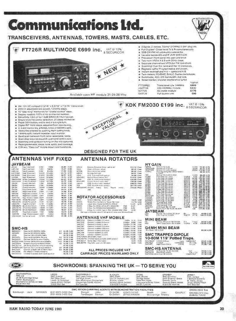
Communications litYAESU
TRANSCEIVERS, ANTENNAS, TOWERS, MASTS, CABLES, ETC.
FT726R MULTIMODE £699 inc. VAT 15%&SECURICOR
Available soon HF module 21-24-28 Mhz
* 3 Bands 2 metres, 70cms (10MHz) & 6M plug -ins.* Full Duplex*. Cross band Tx & Rx simultaneously.* SSB-CVV-FM, All optimumly catered for.* Variable bandwidth and IF shift. SSB & CW* Processor' Front panel mit gain and dove.* Two main VFO'si A & B with 20Hz steps* Separate channelised VFO' (for FM operation).* Scanning' Over the band and the 10 memories.* Repeater splits' Programmable and preset.* Instant reversal! and + & - splits and A/B.* Twin meters. PO/DISC. S/ALC. Duplex switchable.* Switchable. AGC. CW bandwidth, dial lock* Noise blanker, impulse interference tuned.
FT726R(2)430772650T726SAT726
Transceiver c/w 144MHz430-440MHz moduleSix meter moduleFull duplex unit
*option£699£230£170£90
* 2M. 12V DC compact 2 3/16" x 63/16" x 7 3/16" transceiver.* 25W )+ adjustable low power), 12',,khlz steps.* 10 "year long" memories for "crystal control" ease.* Display reads to 100's of Hz or channel number.* Sensitivity <0.2 uV for 1 2dB SINAD (0.14uV typical).* Single knob frequency selection, 20 steps revolution.* Rapid OSY button, end to end in a single turn.* Digital RIT lkHz steps, adjusted from main tuning.* 2, 5 slot memories, simplex, cross or 600kHz split.* Memories entered by pushing main tuning knob.* 1.6mHz split. Instant repeater input monitor.* Band scan between front panel selectable, limits.* Scan stop requires squelch open and centre zero.* Scanning and up/down tuning on the microphones.* Reprogrammable: steps. tone, splits, and coverage.* C/W mic. "Easy out" mobile mount and handbook.
47 KDK FM2030 £1 99 inc. VAT o- 15%& SECURICOR
DESIGNED FOR THE UK
ANTENNAS VHF FIXEDJAYBEAM4Y/4MLW5/2MLW8/2MLW10/214LW16/21.114Y/2MP8M10/2MP81814/21404/2M06/2M08/2MD5/2M08/2M5XY/2M8XY/2MIOXY/2MP81.416/70PE1M24/70LW24/70M8A/2800M81.4411/70
MBM86/708XY/7012XY/70CR2/23CM
Vag' 4 element 23M 7d6d 29.90 2.20you 5 element 1.6M 7 80Bd 14.37 2.50Yaw 8 eterneni 2.8M 9.5084 17.82 2.50Yaw 10 element 3.55M 10 5dttki 24.15 2.50Yaw 16 et1ement 6.54M 13 4d6d 35.07 3.20Yaw 14 element 5.34M 12.84130 36.23 3.2010616 Paranal. 3.93M I 1 7060 44.55 3.2014 *me Paraneam 5.95M 137460 55.77 3.20Quad 4 element 1.5M 94.11d 29.32 2.50Ousd 6 element 2.5M 10 9dEkt 39,10 2.50Quad 8 eiernent 3.54M II 9060 44.55 2.50Yaw 5 over 5 slot 1 6M I OdBd 25.30 2.50Yaw 8 over 8 slot 2 BM 11 1080 34.50 2.50Yaw 5 ele crossed '1.7M 78050 28.17 2.50Yap 8 ele crossed 2.8M 9 5084 35.65 2.50Yaw 10 ele crossed 3.6M 10 &JEW 46.00 2.5018 ele Parebeam 2.8M 13 5c1841 32.20 2.5024 ele Parabearn 4 5M 15 10130 42.55 2.50Yaw 24 element 5.16 14808d 27.02 2.5028 910 Multibearn 125M 115080 21.27 2.5048 elle Multi beam 183M 140d64 35.65 2.5088 ale Multibeam 398M 16 3dEld 48.87 2.50Yaw 8 ele crossed I 5M 10061c1 42.55 2.50Yap. 12 ele crossed 2.66 12013d 52.90 2.50Corner reflector 076M 13 5d13d 40.25 2.50
SMC-HSSMCGDX1 Dtworte 80-480MHz 348'. 33' 40.25 2.50SMCGX2 Dtscone 50-480MHz 348". 6.2' 49.45 2.50GDX4 Otscone 100440 MHz MEP. 33.75 2.50SMCVH FL Decone 65-520MHz Ra only 50' 15.70 2.50SMCGP23 Coltnear 2M 3 a % wave 7.828' 14 6 39.85 2.50SMCGP1441,N Cohnear 2M Multi %wave 6.546' 102' 27.60 2.50SMCGP2M wave c/w ground plane 3448'. 46' 18.00 2.50SMCS0144 2M Swim 0.4 for vertical mounting 57.60 2.50SMCGP432X Coltnear 70cm 3 a 5s wave 6 8481. 5 6' 29.90 2.50SMC702V Colinear 2808'. 2M. 5 7dB, 70cm 36' 29.90 2.50SMC2HB6 61A H89CV 2 Driven elements 19.95 2.50SMCHS770 44/432 Dupleaer 50W 301113 molatton 15.35 1.50
ANTENNA ROTATORSHY GAIN
KR500 Kenpro, Elevation Meter calb 2 90 112.12 Free 12400 vertical 10.15.20 14069508 Channel Master. onset &Lai Free
14400001318AVT/W8
Vert.. 10.1520.40Vertical 10.15.20.40.80M
18 0625.0695028
KR250Channel Master. onsetKentaro, Bell type
56.9254.91
FreeFree
4MA° Root mounting K4 12400 148808 18AVT
AR40 COE Turn and Push control 90.55 Flee 18V Vertical 10.15.20.40.60M 190'HKRWORC KenprO Round meter 360 114.94 Free 1038A
105843 Ele Yaw 10 metros5 Ele Yaw 10 metres
17 crLE 80'618 5'LE braeC045
KR600FICCOE 8 .4 cm meter readoutKentaro Round meter 360
136.55136.30
FreeFree
153BA'55134
3 El* Yaw 15 metresS Ele Yaw .5 metres
23 cYLE 12.01324 5LE 260'8
Ham °,72X
CDE 8 a acrn meter readoutCOE 8 a acrn meter readout
258.75327.75
FreeFree
203842046420564
3 Ele Yaw 20 metres4 EM Yaw 20 metres5 Ele Yew 20 metres
3501E 180'636 5'LE 260'836 S'LE 340'6
KR2000049C Kenpro Heavy Duty Round meter360
314.52 Free 4028420313A
2 EN Yaw NJ metres3 El9560 20 metres
43 O'LE 16.0635011E 160'6
2048A20584
4 61.3'Np 20 metres5 Ele Yaw 20 means
36531E 2e.0'e3851E mot
ROTATOR ACCESSORIES4028401310/158TH3JNR
2 Ele Yaw 40 metres3 Ele Yaw 10-15M3 EC Yaw 10-15-20M
43 O'LE teas230LE 130'62421E 120'8
9523 Support Bearing Upper type 15.81 2.50TH2P4K3TH31.1K3
2 Ele Yaw 10-15-20M3 Ele Yaw 10-15-20M
27 3'LE 60'627 OLE 1408
KS050KC038
Rotary Bearing Kenpro Takes I ka" mastLower Mast Clamp lot KR400.KR600
13.7412.07
2.502.50
TH5DXX166000
-Thunderbird- 5 ER1Thunderbord- 6 Ele
31 O'LE 180'6311'LE 240'6
RC5WRC6W
5 Way For AR30. A540. BT I. KR400RC P/M6 Way For KR250/400/500/600RG P/M
0.370.51
7H7DXXHYOUAD1810
-Thunderbird- 7 EN2 Ele 0084 10.15. 20MMode Tape 10.15, 20. 40 80M
31 OLE 201R1351R 80E1
132RCM 8 Way For CD45. Ham 4. 720.1042000 ORC P/M
Carnage on Rotator cable Cl 80 up to 20 mos 0.120 rntrs 020.55
40 JAYBEAMVR3TB3
009621 10-15-20M DC Snort3 EW Yaw 10-15-20M
610'la 6TR 113
ANTENNAS VHF MOBILESMC2OW Element 144MHz 1/4 wave 008'. 2.30 1.50 MINI BEAMSMC2NESMC2VF
Element 144MHz 5/8 ware 3 OdEr .Element 144MHz '7 wave 3046'
6.9011.50
1.601.50
CA501
Vertocai Mtntalure 10-15-20MOuad beam 10-15-20M
81b 11.5'611 OLE 45'6
5MC78FSMC786SMC88F
Element 144MHz 7/8 wave 4546'.Element 144MHz 7/8 wave 4 506,Element 144MHz 8/8 wave 5 20B'.
138013.5016.60
2.002.002.00
Gi!t MINI BEAMMini
SMC258SMC358
Element 432MHz 2 a 5/8 5 506,Element 432MHz 3 a 5/8 6 348..
12.651655
1.801.80 SMC TRAPPED DIPOLE
SMC7ON2M 2M 270B". 70cm 5 I dB'.SMCHS770 114/432 duolerer 50W 3048...lawn
16.6515.35
1.501.50 10-80M 119' Potted Traps.
SMCGCCA Gutter cite 4 rntrs Cable 9.95 1.50 SMCTD/HP 14SWGH/Dcu traps 1000W PEPSMCSOMN Magneto base c/w 4M cable 995 1.50 SMCTD/P
SMCHPTPortable CullCo.,.ery ne
gt. 1000*'M Power 7MHz75 coax.Per pair
ALL PRICES INCLUDE VATCARRIAGE PRICES MAINLAND ONLY
SMC-HS ANTENNASMCHF50 Verbcal 10.15. 20 40. 80MSMCHFSR Radical Int loadedSMCHF3VNI3Verocal 10-18-24M
50.60 2.7564.40 2.7S
113.65 2.7538.52 2,75
36.22 2.7567.135 3.50
155.25 3.9590.85 3.50
235.90 5.90176.25 4.90256.35 7.30396.75 9.40247.25 6.50176.25 4.90266.35 7 30396.75 9.40247.25 6.50196.95 4.50202.40 3.50169.05 3.50274.65 5.30419.75 6.70396.75 5.50511.75 5.75354.20 6.00121.90 2.50
46.00 2.50189.133.40
59.00 2.50139.00 4.00
82.50 4.00
43.41 2.5059.50 2.5015.52 1.50
15 7' 54.50 2.506 5 -73 34.90 2.50
1000W Pr X 51 35 2.50
SHOWROOMS: SPANNING THE UK - TO SERVE YOUSOUTHAMPTON LEEDS CHESTERFIELD BUCKLEY STOKE GRIMBS/SMC Ltd SMC (Leeds) SMC (Jack Twendyl Ltd SMC (TMR) SMC (Stoke) SMC (Grtmbsy'36-38 RumbrldQe Street 257 Otley Road 102 Koh Street Unit 27, Rtrdold Lane 76 Mph Street 247A Freeman StreetTohon, Southampton Leeds 16, YOrkShtre New Mutt...Won, Chesterfield Buckley, Clwyd Talke Pets, Stoke GrImbsy. 1 incsSouthampton (07031 867333 Leeds (0532) 782326 Chesterfield 102461 453340 Buckley (02441 549563 Kidsgroyet (07816) 72644 Gnmbsy 10462) 593889-5.30 Mon -Sal 9-5.30 Mon -Sat 9-5 Tues Sal 9 30-5 30 Tues-Sal 45 30 Tues-Sat 9 30.5 30 Mon -Sat
SMC STOCK CARRYING AGENTS WITH DEMONSTRATION FACILITIESEdinburgh Jack GM8GEG 1031-657) 2430 Day Bangor John G13KDR 10247) 55162 Neath John
1031-6551 2420 Eve Tandragee Mervyn G13WWY (0752) 840656 Stourbridge Andrew
JERSEYSMC blerSey,1 Belmont GardensSt. Heher, JerseyJersey 105341 7706710-7 Mon -Sat
GW4FO1(0639) 2942 Eve10636)52374 Day103843) 72632
HAM RADIO TODAY JUNE 1983 39

Basic Maths for RAE Studentsby Bill Sparks G8FBX
Part 1: decimals and indices
Most students taking the RAE course have hadlittle reason for studying maths since their schooldays and in most cases have forgotten even theirschool maths. Accordingly they came up against
the immediate problem of sorting out theelementary maths needed at the start of the
course. These notes are an attempt to clear the airby providing a simple explanation of the maths
necessary for the course. Initially the mostimportant factor is an understanding of the
decimal system.
1.0
Fig. L 0.1 0.01 0.001
The decimal point of it allConsider the rectangle shown inFig. 1. The main rectangle is shownas having a unit area of 1.0 and ismade up of ten equal small rec-tangles. (shown as 0.1). Thereforeeach small rectangle is Ihio th of the
large one. We show this 1 1c th as.1 , where the point is called adecimal point and the Latin decimeans /. so by putting the pointin front of the 1 we are indicatingthat we have divided the 1 by 10. Tomake certain of the position of the
point and also to show that the valueindicated is less than 1, we normallywrite the fraction as 0.1. This meansthat the value shown is less than 1.0but greater than '0'.
Referring back to the rectangle,we can further divide by anotherfactor of 10. So that we are nowdividing by 10 X 10 or 100 which isgenerally shown as:
100
The method of indicating this bydecimal notation is to put another 0in front of the 1 but behind thedecimal point:
1,6= .01
Further reference to the rectangleshows that the .01 rectangle can bedivided by 10 and thus we are nowdividing by 10 X 10 X 10 or:
icco
The decimal notation for this valueis .001. At this point a rather signifi-cant fact is displayed.
= 0.1 = (no '0' in front of 1)10
1= 0.01 = (one '0' in front of 1)
100
- 0.001 = (two '0's in front of 1)loxThe number of '0's in front of the 1but after the decimal point is alwaysone less than the '0's in the fractionthus:
1
1000 has three 0's in the fraction butonly two in the decimal. The thing toremember is that the decimal pointin itself always counts as a '0'. Thenumber of '0's in the fraction belowthe line is called the denominator.The number above the line is calledthe numerator.
40 HAM RADIO TODAY JULY 1983

3 X 1,000X 17 X 10,0003 X 103 X 17 X 1043 X 17 X 103 X 1043 X 17 X 10751 X 107510,000,000
IndicesHere is a series of numbers offeredas a typical example:
1
0.000110000
=
0.0011
=1000
0.011
=100
0.1 -=10
and
10-4 x
1 0 1 0 = 103 x 1
10 = 10 = 10' x 1
100 = 10 X 10 = 102 x 1
1030 = 10 X 10 A 10 = 103 x I
10.000 = 10x 10x 10x 10 = 10' x 1
100000 = 10 X 10 X 10X 10A 10 = 105 x 1
1.000,000 = 10 x 10 x 10 10 X 10 X 10 106 x 1
You may notice that the number of'0's following the 1. in the left-handcolumn series of numbers is thesame as those in the centre qolumn,that is it indicates the number of tensin the answer. Typically, 10 X 10 X10 X 10 = 10,000, ie four 0's afterthe 1. By showing this as 104, all weare meaning is that this number(104) is 10 multiplied by itself fourtimes, and is a simple shorthand wayof writing large numbers. As can beseen above it is much easier to write106 than 1,000,000 and also takes upless space. It also helps accuracysince you can easily miss a '0' whencounting such large numbers butthe little number at the top of the 10(this little number is called in indexand two or more are called indices)always tells you how many 0's thereshould be.
In order to understand fully thesystem, here is another look at thesequence in more detail. We have
shown 10 X 10 X 10 as 103 and 10X 10 as 102 so we can say there arethree Os in the first sum which is1,000 and two in the second which is100. Logically therefore 10 on itsown has only one '0' so we can showit as 101, and since 1 has no '0's wecan show it as 10°.
An interesting feature nowarises. If 100 = 102 and 1,000 = 103100 X 1000 = 100,000 = 105 but102 X 103 does not equal 106 but105. Do not multiply the indices,add them. A further example wouldbe:Loco x 10,000 = 10,000,000
= 107x103x 104= 103+ 4 = 107 X 1
This technique enables the handlingof very large numbers with a fairlysimple operation and since it candeal with numbers as small as onemillionth of a millionth of a millionthand as large as 1,000,000,000,000,the importance of this techniquecannot be over -emphasised.
Take for example a multiplica-tion of 3,000 X 170,000, we wouldrewrite this as:
3 X 1,000 x 17 X 10,000= 3 X 103 X 17 X 104= 3 X 17 X 103 X 104= 3 X 17 X 107= 51 X 107= 510,000, COO
(Note 70's).Here is an example combining
knowledge of decimals with know-ledge of indices:
3,140 x 175,600= 3.14 x 1000 x 1.756 x 100, OCO= 3.14x 103x 1.756X 105= 3.14 X 1.756 X 105= 5.51384 x 105 = 551,384,000
or 5 with 8'0'sor 5 x 100,000,000 plus a bit
= 500,000,000 plus a bit.
Obviously such calculations arenormally done on a calculator but
the above shows how to get the ac-tual value of the answer. Thecalculator only gives a string ofnumbers with no indication ofwhether it is in thousands ormillions, because it does not oftenshow the position of the decimalpoint.
The whole technique is aboutmanipulating numbers, and usingthe numbers just like a mechanicuses his tools. We are arranging thenumbers to do things for us.
Since 1 = 10° and 10 = 101then any number between 1 and 10must have a value of index between0 and 1. For example if 100 = 1 and101 = 10 then 5 must have a valuebetween 10' and 10" (between 0and 1). The actual value is .698; and100593 = 5. (0.698 is a value bet-ween 0 and 1.) The actual index forany number between 1 and 10 is nota, direct relationship but is a rela-tionship which alters in a specialform. This relationship is called alogarithmic relationship. The actualindex value is called the logarithmof the number and actual logarithmsfor numbers of 1-10 are shownbelow:
1 = 0.CCO2 = 0.3D13 = 0.4774 = 0.6025 = 0.6886 = 0.7787 = 0.8458 = 0.9039 = 0.954
10 = 1.000
Referring back to these originalnotes we use the indices in multi-plication exactly as describedpreviously. 2 X 2= 4 or 100301 X10030' = 1006°2 and 2 X 2X 2 = 8or 10301 X 10.301 X 103°' = 100503
Next month: square roots,logarithms and decibels.
HAM RADIO TODAY JULY 1983 41

QRXI'll just tunefor a lower
SbWey:SWR - this little abbreviation seems to have developed into a cult overthe years, worshipped almost as a God! Achieving a low SWR of 1:1 is
given a priority almost equal to that of breathing, on the assumption thatas the reflectometer shows the reflected signal must be increasing by the
amount of power shown on the reflected power scale. This is unfortunately(or fortunately, depending on how you look at it,) a load of rubbish.
As we will show - there is no reasonwhy you cannot radiate just as good asignal with an indicated SWR ratio onyour feeder of 2 or 3:1 as at 1: 1!
Without delving into complex equa-tions, or using Smith charts, there are anumber of other common misconcep-tions that can be dispelled, and SWRcan be put into the context into which ittruly belongs. We will have to assumethat you know some of the basics behindthe term, otherwise the article could takeup the whole of this issue.
A point to start from
Let us assume that we have atransmitter connected via a piece ofcoaxial cable with a characteristic im-pedance of 50 ohms, and that a dummyload of resistance 50 ohms is connectedacross the far, or load, end. Also assumethat the cable is lossless (ie. it doesn'thave any resistance or introduce dielec-tric losses), and that there is a perfectlossless reflectometer /power meter in-serted in the line. When you applypower to this set-up, and adjust thetransmitter for maximum power transfer(as shown by the power meter,) current
Fig. 1 Perfect matching: Power in load = VxI
will flow along the feedline and end upbeing dissipated as heat in the loadresistor.
It is important to realise that it iscurrent that is flowing along the line, notpower. The definition of power is the'rate of expenditure of energy'. In ourcase energy can only be used up whenthe current meets some resistance - inthis example the only resistance is that ofthe load resistor. Hence in our perfecttransmission line, no energy is wastedand all the energy generated by thetransmitter ends up as heat in the load.
If we assume that our power outputis 100 watts, and we now replace the 50ohm resistor with another, such that the
SWR will be 3:1, what happens if wedon't (or can't) adjust the transmitter? Ifyou look at the reflectometer under theseconditions, it will be indicating an SWRof 3:1. From the standard formula youcan calculate that this represents an ap-parent reflected power of 25%, or if themeter is calibrated to 100 watts full scaledeflection, it will be saying there are 25watts of power being reflected. Thequestion is, what has happened to this 25watts? The common answer is that it isbeing absorbed by the transmitter (andthat this is likely to cause damage). Itisn't - what has happened is that thetransmitter, because we didn't readjustit, isn't properly tuned to deliver full
42 HAM RADIO TODAY JULY 1983

50, OP100W
500 0/P75W
SWR
BRIDGE50 ANY LENGTH
.111 SWR 1 1
Tx50110/P
100W
STIR
BRIDG
IANLTOAD
ENNA)5011100W
70.5011 ANY LENGTH
SWR 3:
SWR
BRIDGE
.--3MATCHINGIUNIT
d SWR 11
Uo- 500 ANY LENGTH
SWR 31
LOAD(ANTENNA)
x1175W
I LOADENNA)
XII100W
MATCHED SYSTEMTx DELIVERS FULLOUTPUT
MISMATCHED SYSTEM -Tx CANNOT COMPENSATE
Fig. 2 Transmitter can only give full power with a suitable load
MATCHING UNITINTRODUCED TOREGAIN FULL TxPOWER
power into what is now an impedancemismatch, and so its power outputreduces.
The best way of looking at it is to saythat the reflected power meter is tellingyou by how much the TX power outputhas reduced ie. it has dropped by 25watts, so that we now have 75 watts ofoutput into the mismatch rather than 1(X)watts.
If you also had an RF ammeter in theline after the reflectometer you wouldsee that its current reading had drop-ped, which verified the drop in powergoing to the load. Of course you wouldget a different absolute reading depen-ding on where in the feeder the ammeterwas, but we are only interested in therelative current.
So subtract the reflected powerfrom the forward power in watts and youwill have the actual power being passedon to the load.
Getting power backIf your TX is equipped with an ad-
justable output network (ie. tuning andloading controls) such as many valvedrigs have, you will almost certainly beable to adjust these controls to compen-sate for the mismatch, and regain yourfull power output of 1(X) watts. In effect,what you are doing is adjusting the TXoutput circuit so that its impedanceequals that which exists at the line, and itcan therefore deliver maximum poweroutput again.
Most rigs specifiy the maximumSWR that can be handled, and this is anindication of how far you can compen-sate - if the SWR you have got at theend of the feeder is outside this range itwill be necessary to take additional stepsas we will see.
Semiconductor PAs
Those of you with solid state PAsaren't going to be so lucky. Due to thecurrent driven nature of semiconduc-tors, rather than voltage (as in valves)they can only deliver their maximumpower when they are seeing the im-pedance for which they were designed,
or something very close to it. This is nor-mally 50 ohms, and in the majority ofcases you probably haven't got any con-trols to adjust anyway. So if you try work-ing into our theoretical 3:1 SWR system,the PA cannot be returned to compen-sate for the impedance mismatch, withthe result that it will draw excess cur-rent, overheat and lead to an expensiverepair bill. If it is working into a reactivemismatch such as there might be with anaerial connected, things can be worsealthough that doesn't concern us here.
To overcome this sort of damage,the great majority of solid state PAshave some form of SWR protection cir-cuit built in these days. When an SWR ofpossibly 2:1 or more is detected by an in-built bridge, the drive to the PA isreduce to protect it. This is in additionto the reduction in power that themismatch will produce itself. Obviouslysome form of matching network, exter-nal to the system, will have to be in-troduced.
Adding an aerialMoving on a bit, if we now replace
our resistive load at the end of the cablewith a real aerial, you will know that ifthe aerial has the same impedance at itsfeedpoint as that of the feeder cable,then you will feel extremely happy,because the meter will be indicating anSWR of around 1:1. The aerial can ofcourse present a much higher im-pedance and still be resonant, either bydesign, or depending on where you arefeeding it etc., so lets assume that theresulting impedance is such that theSWR is 3:1.
At this point, note that just becausethere is an SWR present, it doesn't meanthat the antenna is losing the power be-ing sent to it. What the SWR is tellingyou is that there is a mismatch presentbetween the source (TX) and the load,however it has arisen.
We have already said that youshould not rely on everything a reflec-tometer tells you. Let's say that yourSWR meter normally reads 1;8:1, anddespite all your valiant efforts it won't goany lower on a particular aerial. If some
friendly person came along in the nightand soldered a 50 ohm resistor acrossthe feeder in place of the aerial, youwould have a nice 1:1 SWR reading thenext morning! A bit extreme, but if yourcable had deteriorated, and smallresistances had developed in all thejoints etc, it is perfectly possible for thesystem to start looking like a resistanceof near 50 ohms. A low SWR cansometimes be very bad news.
So, at this point, although the theoryis outside the scope of this article, try tobear in mind that an SWR of 1: 1 does notnecessarily mean that the antenna isresonant, or that it will radiate morepower, or that the system is efficient.Many aerials, depending on the design,will radiate just as much power with anSWR of 2/3:1 on the feeder as 1:1.Basically, an aerial will radiate all thecurrent that gets applied to its feedpoint,even when the feeder is mismatched atthe antenna feed point, and even withthe antenna off resonance.
Going back to our newly generatedmismatch with an antenna connected, ifwe have a PA with tuning and loadingcontrols we will probably be able tocompensate for the mismatch by twiddl-ing with the controls, and end updelivering 1(X) watts again.
The ATU?
If we have a semiconductor PA or ifthe adjustable TX won't load up properlythen we have a problem. As you are nodoubt aware, this is wher an 'ATU'comes in. Firstly, the ATU doesn't dowhat it says - it does not tune the aerial(at least not when there is a coaxialfeeder involved)! It would more correct-ly be termed an Aerial Matching Unit orAMU, as what it does is to introducesome more variables into the system andallow the impedance seen by its output(which is currently a mismatch to the TX)to be transformed into the correct im-pedance at is input terminals for theTX, again usually 50 ohms to suit thecable which will be connecting the twotogether.
Another point arises here and that isthe correct way of using the matchingunit. Normally you firstly tune up the TXinto a (50 ohm) dummy load, both to getit tuned for its optimum output, andsecondly to avoid poluting the airwaveswith carrier. Having done that you thenadjust the matching unit, with a reflec-tometer inserted between the TX andmatching unit, for an indicated SWR ofclose to 1: 1, thus showing that the TX isnow seeing 50 ohms again.
If you have a filter in the line forharmonic rejection, you shouldn't thenreadjust the TX controls, as you maydestroy the 50 ohm impedance you havejust created. Otherwise if you move fre-quency a little you can either readjustthe AMU, or the TX, providing the latter
HAM RADIO TODAY JULY 1983 43

still allows you to achieve a propertransfer of power. Of course there willbe a small power loss in the matchingunit through losses in the inductors andcapacitors, but in a decent unit these aresmall enough to forget about.
So fax we have used the SWRreading to tell us about, and compensatefor, mismatches between the TX and thefeeder, so that the transmitter candeliver its maximum power into the load.
The 'aerial tuning'syndrome
It is at this point that the biggeststumbling block arises when using amatching unit. So many times you willhear stations announce that they havejust tuned the antenna for a 1:1 SWRwith the ATU, when they have in factdone nothing of the sort. What they havedone is simply to adjust the matchingunit so that the transmitter can see itscorrect load impedance - the SWR onthe feeder from the output of the mat-ching unit is still whatever it was in thefirst place!
Earlier on, we started with theassumption that we had a perfect losslessfeeder system, which of course we don'thave in practice. Now, the only way wecan lose power is by dissipating some ofthe current in resistance in one form oranother. We have already shown that itis possible by one means or another toget the full TX power intocable, but what happens along this cablewhich still has an SWR on it - does thismean we are losing lots of power?
Once there is a mismatch, we in-troduce standing waves along the cable,where the ratios of current and voltagevary at any point along the line, butrepeating at half -wavelength intervals(electrical half -wavelengths). In fact, theaverage current and voltage is higheroverall on a mismatched line than a mat-ched one. The power meter will tell youthis by reading a higher forward poweron a mismatched line than it did for thesame line when matched.
There isn't actually a higher forwardpower as such - what is happening isthat the 'reflected power' shown on yourSWR meter is again reflected by theAMU back towards the load but is now inphase with the forward current, andadds to the forward power reading - it'sknown as conjugate matching and isreally what this article is all about, werewe to be discussing mathematics. Theresult is that the higher voltage in-troduces some loss of power by dielec-tric heating, and the extra current a bitmore by resistive losses in the conduc-tor.
How much loss?
Contrary to popular belief, theselosses are small in the normal system,
and do not contribute much loss to thesignal that is reaching the antenna. AtHF, say 7MHz, a 10() metre length oftypical 50 ohm coaxial cable will havean additional loss over that which will bethere anyway when it is perfectly mat-ched, of only 0.27dB at an SWR of 3:1!This is a 6.4% power loss, insignificantif you look at it in S -meter terms whereone S point requires a 6dB increase inpower.
As long as the transmitter is deliver-ing its rated power into its correct loadimpedance, by whatever means, then allbut that lost in the matching unit, andthe fraction of dB in the feeder will getradiated by the aerial into space. If youinsert an SWR bridge into the feeder, itwill correctly tell you that we have a 3: 1
SWR, and also that this represents 25%power loss - however this latter fact isirrelevant as a bald statement of fact. Weknow that the SWR is 1: 1 at the input tothe matching unit, because we alreadyadjusted it to be so.
Therefore, if you believe the'reflected power' reading, then 25 wattsmost be being absorbed by the matchingunit, as it can't be going anywhere else- if it is being absorbed then it will beconverted into heat so that the matchingunit will get rather hot. Which of courseit doesn't.
You should be able to deduce fromall this that if you have a PA which is ad-justable, or a suitable matching unit,then once you have compensated for themismatch, and managed to get all yourpower going into the feeder, there is lit-tle point in trying to do anything aboutthe SWR on the feeder itself. It will have
next to no effect. Of course, with verylong coaxial feeder runs, and atVHF/UHF, the mismatch loss in thefeeder becomes much more important asit may be high enough to affect thesignal. What we have been trying to sayis that there is little point trying toachieve a low SWR for its own sake.Other factors may modify this decisionbut at HF it is probably a wasted effort.
With something like an 80 metredipole, there is consequently no point atall in considering where in the band toadjust it for resonance as indicated by a1:1 SWR. Providing you can compensatefor the mismatch at the TX end, youshould be radiating the same signal at3.5 as at 3.8MHz, despite high SWR atone end and low at the other.
FinaleAs a final note, if your transmitter
loads happily into the feeder, you mightbe better off not being influenced by anSWR meter in the first place. It may evenbe telling you lies! Unless you are usinga good quality instrument that is design-ed for exactly the same impedance cableas you are using it in, then you areunlikely to be getting an accuratereading anyway, although it may be cor-rectly indicating that the ratio is low.
Most of the cheaper instruments onthe market give varying readings depen-ding on the frequency and the powerlevel in use. They may even changereading as you watch them and give youthe impression that your power is fallingoff. The writer has a selection of bridges- few of them agree on the ratio obtain-ed.
44 HAM RADIO TODAY JULY 1983

The ResistanceSWR Bridge
By Tony Bailey G3WPO
For most pieces of equipment in ourhobby, there are many designs. Inthe case of the well know SWRbridge some are fairly simple,others are complicated. The degreeof accuracy depends on the design,and the amount of effort put into theconstruction and calibration.
The principle behind this typeof bridge is simple. A suitablesampling device is used to obtain asmall voltage from the line undertest, which is then rectified bydiodes. By comparing the voltagesobtained from the forward andreflected currents in the line, ameter can indicate the StandingWave Ratio on the line.
The three most popular circuitsare the trough type, where a pair ofshort sampling lines are placed ad-jacent to a central conductor carry-ing the RF current, and the voltageinduced in each line is used to pro-vide the reference for themeasurements; the 'Monimatch'which uses a similar principle, butuses a sampling line threaded downthrough a piece of coax cable bet-ween the outer and inner conduc-tors; and the current transformertype where a toroidal transformersamples the current flowing throughthe line - the primary of thetransformer being a single stretch ofwire carrying the RF current andpassing through the toroid, with thesecondary wound round the toroiditself.
The first two types suffer fromfrequency consciousness, as theelectrical length of the samplingline varies with frequency, hencethe readings and sensitivity alsovary. Some care in contruction isneeded for reliable results. Thetransformer type is more accurate,but is much more elaborate andcomplicated to build. It does have
the advantage of being frequencyindependent though.
A simpler bridge
There is a simpler type of SWRbridge which seems to have beengiven little attention in recent years,but which is ideally suited to thebeginner, and is easy to build. Itdoes have the disadvantage of onlybeing suitable for low power, andcannot be left in circuit once thetuning operation is finished.However, it has a minimal partscount, and with a little care in con-struction gives accurate results. It isideally suited to QRP work, andcould form the basis of a combinedQRP antenna matching unit andSWR bridge.
V in
For V=0
_ R2then RL - RsRI
Fig. 1 Theoretical resistancebridge
The resistance bridge
Fig. 1 shows a simple resistancebridge which basically consists oftwo voltage dividers in parallelplaced across a voltage source.Whenever the voltage drop acrossR 1 equals that across R2, then thedrops across the other two resistorsare also equal. The two junctionpoints of the divider chains aretherefore at equal potentials and themeter reads zero, giving a balancedbridge.
If the voltage drops across RIand 2 are not equal, then the twojunction points are at different
potentials, the bridge becomes un-balanced, and the meter will readthe difference potential.
SWR bridge
If we now make RI and R2 ofequal value, then a balanced condi-tion will exist whenever the othertwo resistors are equal in value. If Rsis made equal to the characteristicimpedance of our transmission line(say 50 ohms), and RL is replaced bya feeder, then the bridge will bebalanced whenever the load im-pedance is equal to 50 ohms. (SeeFig. 2.)
Fig. 2 Theoretical SWR bridge
If the bridge becomes unbalanced then as RF current travelling towards the load only 'sees' theimpedance of the line until itreaches the load, the bridge is stillbalanced for forward current, as ithas to pass through Rs en route. Thepower reflected from the loaddoesn't see the bridge circuit andhence this registers on thevoltmeter.
If we measure the forwardvoltage at point A (which is equal tohalf the applied voltage), and com-pare this with the measuredreflected voltage, we can calculate
HAM RADIO TODAY JULY 198345

the SWR from the usual formula:Vf Vr
SWR =Vf Vr
Points to note
To prevent inaccuracies, thevoltmeter must have a highresistance, otherwise the currenttaken by it will be large comparedwith the current flowing through thearms of the bridge. Alternatively, ahigh value resistor can be placed inseries with the voltmeter, which willalso suit the germanium diode rec-tifier we shall use for converting theRF to DC voltage.
If you wish to measure accurate-ly the actual SWR value, it is alsonecessary to be able to measure theinput forward and reflected voltagesseparately. When we measure theforward voltage the load has to bedisconnected at RI (either by shor-ting it out or disconnecting it).When RI is reconnected (in theshape of our feeder), the load on thevoltage source will be different, andcould affect the applied voltageleading to errors in the readings.
However, in line with keepingthings simple, you can almost cer-tainly get away with just using thereflected voltage meter - this willenable you to tune for a null in thereading, informing you that theSWR is now at a low figure, which ismore than adequate.
Hence our practical circuitdispenses with the input rectifierand meter and uses a bit of swit-ching to enable calibration. One ad-vantage of the circuit is that due tothe presence of the series resistor,the transmitter sees a relatively con-stant impedance during tuning upoperations which may be of benefitwith semiconductor PAs.
Practicalities
The circuit of the practicalmeter is shown in Fig. 3. As shown,it will be suitable for a maximum ap-plied RF output of 5 watts or so, pro-viding the resistors are of thespecified power rating - they mustnot be wirewound types which havetoo much inductance. The diodemust be germanium - an 0A90/91(not gold bonded) is suitable. Themeter can be any lmA type - itshould be possible to achieve fullscale deflection with around 50mWof RF power in this circuit.
Construction is not particularlycritical except for one point. Thebridge arms should be positioned sothat coupling between them isminimised. Also avoid coupling bet-ween the rectifier diode and the re-mainder of the circuit. The two 47ohm resistors should be equal invalue (although not necessarily ex-actly 47 ohms - one can be care-fully filed if necessary to bring itsvalue up to that of the other) andhave equal lead lengths, both asshort as possible. Also, keep allother leads as short as possible tominimise inductance, which wouldspoil the bridge performance athigh frequencies.
The coaxial cable whichbypasses the unit should be ground-ed at both ends. A practical layout isshown in Fig. 4 - this can either bewired using the S0239 sockets and afew tagstrips as supports, or thebridge could be built on a printed
1 =Set meter2 =Tune3 . Operate 5011 coax
It 3
Tx 0-00°' 2
R2
R3
R1
Load0
0A91
1k 05W
Calibrate
10klin
1mAt s d
Fig. 3 Practical bridge layout
circuit board.
Using the meter
To check out the finished meter,place the switch in the SET position(which removes any load from thebridge output) and apply a max-imum of 5 watts to the input socket(or use the TX at lower power). Nowadjust the potentiometer for fullscale deflection on the meter. Con-necting a suitable dummy load tothe output terminals should nowgive a reading of zero at all frequen-cies from 1.8 - 30MHz. If thereading increases as the frequencyincreases, there is some unbalancein the bridge, probably caused bythe stray capacitance or inductancein one arm of the bridge not beingexactly equal to that of the other.
Slight movement of componentsmay cure this. If the meter shows aconstant reading ie. it cannot benulled, then the load resistor is notequal to that of the series resistor(R3).
To use the bridge with a mat-ching unit inserted in the line afterthe unit, load up the transmitter asbefore in the SET position, and ad-just the pot for FSD on the meter. Ifthe TX is fixed tuned, simply adjustfor FSD. Place 51 in the TUNE posi-
tion with the feeder or antenna con-nected, and adjust the matchingunit for a minimum reading on themeter showing that the SWR is nowat a low value, and then switch to theOPERATE position to bypass theunit.
"PeX4P/N----"7""He claims it's something to dowith contest operating.".
46 HAM RADIO TODAY JULY 1983

NEW PRODUCTSFT29OR preamp
Mutek Ltd. is introducing anew 2m preamp specifically forthe Yaesu FT290R transceiver.The SLNA 145th TransceiverOptimised Preamplifier isintended to cure the FT29OR'salleged deafness, and it has beendesigned to fit inside thetransceiver.
Mutek claims it provides asensitivity improvement sufficientto ensure that external noise isthe limiting factor, whileminimising dynamic noisedegradation.
Other benefits claimed for thepreamp are improved front-endselectivity, and an on -boardnitrogen -filled changeover relay(to eliminate the losses in Yaesu'sdiode switching).
The provisional specificationis: noise figure 1dB; gain variable0-15dB; input third orderintercept +2dBm; input 1dBcompression point -14dBm; 1dBbandwidth 4MHz; 20dBbandwidth 12MHz; relay powerhandling 40W (VSWR less than2:1); size approx.53 X35X15mm.
The SLNA 145th retails at£24.90 inc VAT. For furtherdetails contact Stephen Prior orChris Bertram at Mutek Ltd.,Bradworthy, Holsworthy, DevonEX22 7TU Tel 0409 24548
Feeder spacerIf you have found making
open wire balanced feedersrather time consuming thisproduct should be of interest. TheG40GP Spacer is simply a bit ofplastic that can be clipped on toa pair of wires to hold them63mm (21/2") apart.
The spacers are made out ofultra -violet stabilised co -polymerpolypropylene, which means theyshouldn't decay when exposed tothe weather.
The characteristic impedanceof feeders made with thesespacers is normally in the300-600 ohm range, dependingon the guage and insulation ofthe wires used
The recommended retail priceis £10 for a pack of 20 spacers.They are also available by postfrom the manufacturer at a cost of£10.99 inc. postage andpacking. Orders/enquiries toG40GP Electronics, 116Darlington Street East, Wigan,Lancs. Tel 0695 27948.
10MHz trapsKW -30 aerial traps allow
trapped dipole coverage of the10.1-10.15MHz amateur band.The manufacturer says that ahigh Q -factor is obtained by"optimum form factor onpolystyrene".
The coil is designed to handle2kW PEP and it weighs sixounces. It is 5.5" long by 1.8"diameter, and has a tensilestrength of 800 lbs. An acryliclacquer waterproof coating andall -aluminium hardware help toprevent corrosion.
A pair of KW -30 traps costs$32. Further details from EmilyBostock, Microwave Filter Co.,Inc., 6743 Kinne Street, EastSyracuse, NY 13057, USA. Tel(0101) 315-437-3953.
Double balancedmixers
PM Electronic Services nowcarries two new types of doublebalanced mixer, the M-8 andM-18, made by R&KLaboratories, in place of theMD108 and SL I formerlystocked. These plug-in,broadband mixers cover the
fi0OkHz-500MHz range (down to
DC on the IF port) withinput/output impedances of 50ohms. They are housed in an 8pin, 0.2 inch pin spacingpackage, and can be mountedeither by plugging into miniaturerelay sockets with a 0.2 X 0.2inch grid, or by soldering directlyto the PCB.
The M-18 costs £7 inc. VAT.The M-8, which has hermeticsealing and more than 90dB ofradiation shielding, costs £9 inc.VAT.
Further details from PMElectronic Services, 2 AlexanderDrive, Heswall, Wirral,Merseyside L61 6XT. Tel051-342 4443.
Specialist VHFaerials
South West Aerial Systems isintroducing a number of aerialsfor the amateur VHF enthusiast,having previously beenconcerned mainly with longdistance broadcast reception.
One of the new aerials is acrossed dipole/reflectorarrangement for satellite workingon 2m (shown in photo).
Two other aerials aredesigned for the experimental50MHz band. The NB52 is a two -element beam covering50-52MHz at a nominalimpedance of 50 ohms. TheNBS4 covers the full 50-54MHzrange. (75 ohm versions are alsoavailable.)
The claimed specification forthese 50MHz arrays is: midbandgain 4.7dBd; front/back ratio8-9dB. The boom is 4' 9" longand 1" in diameter.
The 50MHz arrays cost£22.75 inc. VAT and Securicordelivery from South West AerialSystems, 10 Old Boundary Road,Shaftesbury, North Dorset. Tel0747 4370.
BOOK:VHF/UHF Manual
The RSGB's VHF/UHF Manualalready has a reputation forbeing something of a 'bible'. Thisnew fourth edition looks likeboosting that belief. At twice thesize of the earliest editions, thisbook is stuffed solid with 528pages of invaluable informationfor the VHF/UHF experimenter.
As well as chapters onbackground and theory, there aremany practical designs, oftenwith a choice of technologies -for instance there are designs forvalve, transistor and power-FET144MHz transverters. Many ofthe designs have not beenpublished before.
The chapter titles are:Historical perspectives;Propagation; Tuned circuits;Receivers; Transmitters; Inte-grated equipment; Filters;Antennas; Microwaves; Spacecommunications; Test equipment.There is also an appendix withdata such as colour codes forresistors and fixedceramic/tantalum/polyestercapacitors, charts showing theinductance of coils and graphsshowing the characteristicimpedance of PCB tracks ondouble sided boards. Thisappendix also contains a wealthof data on coaxial cables,waveguides , coaxial connectors,PA valves, power transistors,double -balanced mixers, powerFETs, broadband cascadeamplifier modules and batteries.There are also tables of wireguages, decibels againstvoltage/power ratio and dBmagainst voltage (for 50 ohm and600 ohm systems), and a table ofresistor values for 50 ohmT-attenuators.
The VHF/UHF Manual isavailable from the RSGB, AlmaHouse, Cranborne Road, PottersBar, Herts. EN6 3JW for £8.50(£10.31 by post worldwide).
This book is excellent.
HAM RADIO TODAY JULY 1983 47
Advertising copy dates LOSING DX?August issueSeptember issue
31st May5th July
Phone Lynn Collis on (01) 437 1002 todiscuss your copy details.HAM RADIO TODAY the onlyamateur radio magazine that youdon't have to have a degree inelectronics to decipher.
ANTENNA FAULT? Poor reports? Check FAST with anAntenna Noise Bridge, MEASURE resonance1-150MHz and radiation resistance 2-1000 ohms,MORE DX, £18.60
SPEECH COMPRESSOR, make them hear you. £15.30TIME WRONG? MSF CLOCK is ALWAYS CORRECT -
never gains or loses, SELF SETTING at switch -on, 8digits show Date, Hours, Minutes and Seconds. alsoparallel BCD (including Weekday) output for computeretc, receives Rugby 60KHz atomic time signals, built-inantenna, 1000Km range. TIME RIGHT, £69.60
HURRY, prices go up at end of July, each fun -to -build kitincludes all parts, printed circuit, case, by -return postageetc, money back assurance so GET yours NOW.
CAMBRIDGE KITS45 (GU) Old School Lane, Milton, Cambridge
THE CW/RTTY COMMUNICATIONS TERMINAL
mirrmint A.
rommermilL £381.74 inc. carriage(Standard unot cost VAT not Included(
Forget.all those messy wires, theMICRODOT now offers a totallyintegrated communications system.
Write for full details to .
POLEMARK LtdLower Gower Road
-1111111.111111.111111 Royston, Herts SG8 5EATel. Royston (0763) 47874
sell11111k
STANDARD FEATURES INCLUDE Integral high resolution video monitor Professional keyboard with many special functions Real-time clock (constantly displayed) Transmit and receive both CW (morsel and RTTY
(teleprinter) Users callsign programmed in Receive CW speed tracking and display Self checking facility Char. by char. or 'page' transmission modes Stylish two tone metal cabinet
OPTIONAL FEATURESPrinter interface boara (Centronics compatible)
On -board 40 column printer (12V) External 00 column printer (SEIKOSHA GP100A)
THE Co CENTRE10 MERTON PARK PARADE,
KINGSTON ROAD, LONDON SW19(JUNCT. MERTON HALL RD)
TEL 01-543 5150
LONDON'S NEWEST AND BRIGHTEST EMPORIUM(NEW
30 foot mastPRODUCT
telescopicideal for
portable use£28.00
TRIOYAESU-ICOMStandard-FDK
Azden-JaybeamWelz-DaiwaTono-SMC
KDK
SLIM JIM2 metres70 cms
Complete with4 metres co -ax
£8.50Inc. P - P
INSTANTCREDIT NOWAVAILABLEup to £1000
throughLombard
Tricity
NEWRANGE
JUST ARRIVEDDaiwa Cross
pointer metersantenna tuners
etc.
THE NEWG4HXZ
MORSE TAPEInc. 2 simulated
Morse Tests£3.50
Inc. P P
GOODSELECTIONof R.S.G.B.Publications
Now In Stock
URGENTLYREQUIRED
Working or notall s/hand eqpt.
Try us lastwhen selling
your gear
NEWPRODUCT
23cms A.T.V.Receive converter
just plug intoyour home TV.
£29.50Inc. P P
HB9-CV2 element2 metre or
70cms BeamNow available
Mail Order£9.50
LARGESELECTIONof lashing kitPoles -ClampsRotators -CableJaybeam-Tet
Tonna-etc.
THENEW SX-200N
VHF UHF Scanner£265.00 also the
new MagnumVHF Receiver
Lo -hi Band£99 Inc.
THEFULL RANGE
of theMicrowave Module
ProductsAvailable
BACCESS
ETC.MAIL AND
TELEPHONESERVICE
48 HAM RADIO TODAY JULY 1983

Upgrading the
11011/2000series of HFtransceivers
Part SMore Modsby M.T. Healey, G3TNO
and R. Charles
The note on most KW2000s leaves alittle to be desired to the CW puristsand the example at G 3TNO was noexception. A number of criticalreports on the note were obtainedfrom local and more distant stations,including a most useful tape of thetransmission from an SWL (needlessto say, he received a QSL byreturn). It became obvious from thetape, various reports and localmonitoring that the signal sufferedfrom clicks on 'make', and thumpson 'break', and that the tone had arather odd 'flutey' sound. Variousexperiments were tried with theusual key click/thump filter circuits,but none really cured the problem,so thoughts turned to an alternativemethod of generating the CWsignal.
The KW2000 was tuned up intoa dummy load, and another receiverwas used to monitor the signal pro-duced. The balanced modulator wasthen temporarily unbalanced byshorting one side of the balancecontrol RV14 to chassis, and theresultant carrier monitored on theoutboard receiver; the note wasperfect. So an external power supp-
via a key to thejunction of C6 and C7, a CR net-work being connected across thekey contacts. The monitored notewas now perfect with no trace ofclick or thump. This set up perform-ed well on the lower bands, but on21&28MHz a severe lack of drivewas apparent, caused by the fact
Amplitude
Frequency --..- A
3kHz
B
Fig. 105 The position of the car-rier with respect to the filterpassband. For SSB operation thecarrier frequency is normally setto position A, some way downthe skirts of the filter response, sothat the filter passes the uppersideband and filters out thelower. For CW operation moredrive will be obtained if the car-rier is moved to position B, in thecentre of the passband.
that the carrier in most SSB rigs isset to a frequency which is about20dB down one side of the filterpassband, as shown in Fig. 105. So acrystal in the centre of the passbandwas plugged into the socket normal-ly occupied by the LSB carriercrystal, and again the note wasmonitored and the drive levelchecked; the note was still OK andthere was now plenty of driveavailable on all bands. A few localcontacts were made using this lashup, and everyone reported a greatimprovement in the transmission.
A list was now drawn up of therequirements for a permanentmodification:1) The ability to unbalance thebalanced modulator with the key,without using an external powersupply.2) The automatic switching in, inthe transmit mode only, of a carriercrystal in the centre of the SSB filterpassband, reverting to the normalcarrier crystal on receive.
After many trials and errors thecircuit of Fig. 106 was evolved. Theadvantage of this circuit, apart froman improved CW note, is that, at theflick of a switch (S1"), it is possibleto revert to the unmodified state;thus the SSB performance is un-changed, and comparison betweenthe modified and unmodified statesis very easy.
The operation of the circuit is asfollows. With SI set to ON, andunder key -up conditions, TR4 andTR5 are biased off, so no voltage willappear across R1003 or across thecoil of relay C. The sidetoneoscillator will be cut off, and withthe rig set to VOX the contacts of theVOX relay RL4 will be open; thusthe rig will be in receive with theCW filter switched into circuit. Atthe instant of closing the key con-tracts, TR5 is biased on, relay C isenergised and a carrier crystal inthe centre of the SSB filter passbandis switched into circuit. Thesidetone oscillator in the KW2000will at the same time activate theVOX circuit, putting the rig intotransmit. This will close contactsRL4/2 and will keep TR5 biased onvia D112. This latter feature isvery important, as without it relay Cwill follow the keying, and the
" Note that the switch 'Si' referred toin this article is not the same switchas on the original KW circuit.
HAM RADIO TODAY JULY 1983 49

To sidetoneoscillator
R1005
470}.1 B8z8y
c oD114 -BAX16
- 0110 R1000 R1001
To key BAX16 10k
01000470n
22k
C1001 .1.470n
R1002 1.
470 1W
TR4
6(7.11
R1004 D112.113
To wiper of Si (Fiig.104)
To C6 (Audio__
catholdre7ollowerlAli
1k5
R1003C100247010u
BA X16
To junction of(ll RFC1and C7
bInlanput
edbalancedmodulator)
a c
2nd 1/2 of SiI SSB/CW switch)
D111
BAX16V D112"""BAX16
R1007
R1008
27k
SKT3 3
Fig. 106
R1006
470
TR5
LBCY*7fl
Carrier osc.I.
RL4/2 c)
Relay C C1163
° V Coil of op,relay ad
455
TB
C117 g RFCoC
kHz
Xtal To LSB/USBswitch S5C
outgoing transmission will soundlike a cross between FSK and nor-mal on/off CW! TR5 will stay biasedon during the hold -in time of theVOX cirucit, or for as long as the rigis held in transmit by the INT MOXsetting or by an externalsend/receive switch, provided thatSI is set to the CW position. Alsounder key down conditions TR4 isbiased on via D110, R1000 andRICCI, the turn -on and turn-offtimes being controlled by R1OCO,R1001, R1002, C1000, C1001 andC1002. These components are re-quired to completely remove anythumps or clicks on the signal; thereis therefore no need for further keyclick filters across the key or keyercontacts, and in fact they arepositively harmful to the operationof this circuit.
When TR4 is biased on (keydown), a voltage is developedacross R1003 and C1002. Thisvoltage is fed via R1004, D112, D113and the second pole of Si to the LFinput of the balanced modulator,thus unbalancing it and producingacarrier at its output. This carrierwill, of course, be fed on to the laterstages of the transmitter. The twodiodes D112 and D113 are used toprevent any slight leakage in TR4unbalancing the modulator, whichwould, or course, produce a carrierunder key -up conditions. D114prevents this circuit being activatedin the TUNE mode.
Variable transmitteroutput power
It has been found useful to beable to vary the output power of theKW2000when, for example, drivinga transverter or linear amplifier. Asthe rig stands there is no way of do-ing this except by adjusting the MICGAIN control, which is a veryundesirable way of varying poweroutput, particularly at low outputlevels. Although the ratio of peakoutput power to the suppressed car-rier at normal mic gain settings maywell exceed 40dB, as the mic gain is
R18
To ALC
R17
HT +
56k 2W
R19 R21
40
C19
R20
I
C17
1200
5k5W
0/P to
M/filter
100n
Fig. 120
54 position
1
1.IRT2 -OFF3= ITT
IRTT
R -see textTo relay supply
(Approx 16V)
Spare water on S4
Fig. 121
reduced the carrier level due toleakage round the balancedmodulator will remain the samewhile the peak output power will bereduced. Thus the effective carriersuppression will be reduced. Thewriters feel that it is best to vary theoutput power after the balancedmodulator, and this can most easilybe done by varying the gain of thetransmit IF amplifier V3, which is inany case a variable -mu valve con-trolled by the ALC.
The simplest way of controllingV3 without upsetting the ALC actionis to insert a variable resistor in thecathode circuit to vary the bias. Acircuit for doing this, employing only three extra components, is shownin Fig. 120. At full gain the outputlevel is the same as with an un-modified KW2000, while atminimum gain it is possible for theoutput to be reduced to below onewatt! This method leaves the micgain control set as for normal opera-tion, giving the advantage that atlow power output levels the carriersuppression is not degraded.
IRT IN USE indicator
A small but useful extra featurehas been the addition of a warningLED to indicate that the IRT/ITTselector switch is on. The extra swit-ching for this is already fitted,although left unused. There is aspare pole on S4, which can bewired as shown in Fig. 121. The LEDis conveniently mounted approx-imately 11/4 " to the left of the switch.The value of the series resistordepends on the particular LED usedand the brightness required.
The next article, in ourSeptember issue, will deal with theimportant question of modifying theKW2000 to cover the 10, 18 and24MHz bands, as well as the missingsections of the exisitingbands.
50 HAM RADIO TODAY JULY 1983

NEXTMONTH
SPECIAL PROJECT SPECIAL PROJECT SPECIAL PROJECT SPECIAL PROJECT SPECIAL PROJECT SPECIAL PROJECT
VHF TO HF TRANSVERTER
* Use your 2m multimode transceiver on 20,15 and 10 metres with our new constructional add-on
* Full transmit and receive capability allows all the features of your 2m set on the HF bands. High performance linear operation
* Work the world with a VHF handitalkie
* Easy to make with a complete kit of parts available
PLUS All the regular features that you have come to expect from HAM RADIO TODAY
SLIMLINE MASTS or LATTICE TOWERSFIXED TOWERS or MOBILE TRAILERS
THE WAY AHEAD
PORTABLE MASTS or WINDOW MOUNTINGYOU NAME IT! WE PROBABLY MAKE IT!
SOME TYPICAL DESIGN FEATURES VERSATILE MOUNTING, POST, WALL OR TRAILER. UNIQUE 15FT SECTIONS FOR MINIMUM LOWERED
HEIGHT AND EASY TRANSPORT. (CAN HELP PLANNING) PURPOSE DESIGNED AND ENGINEERED TO B.S.I.
STANDARDS. WIND LOADS TO CP3 CHAP V PT 2 ROBUSTLY CONSTRUCTED IN QUALITY STEEL (TO BS
1775. BS 980. BS 4360) OPTIONAL HEAD UNfTS (Extra).
WELDED BY ELECTRONICALLY CONTROLLED M.I.G. FOREXTRA STRENGTH TO BS 4872.
MORE THAN 50 TYPES OF MAST OR TOWER FROM 30FrTO OVER 100FT.
TELESCOPIC TILTOVER FOR EASY ACCESS. SAFETY LATCH TO RELIEVE CABLE. SIMPLE WINCH OPERATION (Single and Double). HOT DIP GALVANIZED FOR PROTECTION (BS 729).
A FEW POPULAR MODELS FROM OUR WIDE RANGESLIMLINE MAST SM30, Unobtrusive, Telescopic, Tiltover,up to 3111. SM3OWM (Wall Mount) E230.00. SM3OPM (PostMounting) £241.00, Optional Reducer Tube RT1 £12.50. RotorHead RH1 £30.50. Ground Socket GS1 £23.50.
LATTICE TOWERS - TELESCOPIC - TILTOVERSeries 1. 32AT.AT32PM for £363.00. AT32WM £348.00Series 2. Heavy duty 44ft AT42PM £461.50. AT42WM£445.00. 56ft. AT52PM £599.50. AT52WM E579.00.
Prices include all winches, luffing gear, brackets, head unitetc. As applicable. Mainland carriage (door to door), AndVAT @ 15%. Terms C.W.O. Send for details.Prices may alter. Please allow up to 28 days for delwery.
We design - we make - we supply direct. At manufacturers prices. You get bestvalue and service. We offer no gimmicks. No free gifts.
Just competitive prices, quality, reliability and know how.Don't delay send 6x9 SAE for literature.
Cal'ers welcome./Samples on display. Opening hours: Mon-Frt. 9 am -5 pm.Sat. 9 am -12.45 pm.
ALL ALTRON PRODUCTS ARE EXCLUSIVELY MANUFACTURED IN THE U.K BY
ALLWELD ENGINEERINGUNIT 6, 232 SELSDON ROAD, SOUTH CROYDON, SURREY CR2 6PL.
Telephone.01-680 2995 124 hr) 01-681 6734
BARCI AsTARO
VISA
HAM RADIO TODAY JULY 1983 51

My QTHisn't very high...
A good take -off?Ever dreamt of moving your house to the top of amountain somewhere? You might be better off on
the low ground than you think you are.By Frank Ogden G4JST, Editor.
The houses around your QTHmight look like obstructions tothe operator, but they can serve.to boqpt your signal by up to
There seems to be only one generalview of the optimum VHF QTH: atthe top of a hill with nothingobstructing the view for miles. If atall possible, it should be arrangedthat the ground around slopesgently down on all sides to the plainway below. For preference, thereshould be no trees, pylons,buildings or anything else to break-up the smooth contour of the land.
A QTH fitting the abovedescription would be a desirableplace to set up a VHF/UHF station inone respect only, line of sightcommunications. Height, pure andsimple, does not affect troposphericDX as much as one might imagine.
Not a perfect mirrorTo understand the point, one
needs to appreciate a few of thesubtleties of VHF/UHF tropopropagation. The sky is very muchless than a perfect mirror. Therefractive index interface whichproduces DX conditions is a) not acontinuous sheet and b) a refractorrather than a reflector. Tropobending occurs under inversionconditions: dense but humid coldair sits on top of warmer, dryer airclose to the surface of the ground.This produces something like adielectric waveguide which has, onone side, the warm air close to theground, and on the other, the
rarefied thin stratosphere on theother. The conducting strand ofcold but humid air sits trappedbetween the two.
This duct can carry signals forHX and occasionally 1000s of milesalong the whole length of a weatherfront. Once signals have enteredinto the duct, they will not emergeand radiate back to earth until alocal atmospheric disturbance suchas a strong thermal lets the signalout. The graded index optical fibreprovides an excellent analogy totropospheric propagation. Therefractive index of the fibre altersacross its cross section such thatlight entering the fibre tends to bereflected towards the middle whereit stays for the passage down thefibre.
If one makes a nick or a break inoptical fibre, the light floods out atthe discontinuity and scatters in alldirections. Tropo ducts behave inprecisely the same way. Eventhough DX paths may exist within aplate of tropo ducting (rememberthat a tropo duct is more like anelongated plate than a wire) youwon't necessarily gain access to itunless your aerial is sufficientlyclose to a discontinuity to fire into it.
Height no advantage
The effects of these 'holes' canbe heard during any lift. There arelarge numbers of discontinuities inthe sheet, each of which has aconstantly changing characteristic.This translates into the peaks andfades in received signal strength.Signals from the other side of thecountry may come in at 33dB overS9 while closer stations (or stationsfurther out) may produce signals atthe limits of audibility. This situationcan reverse itself in the course of acouple of minutes.
The actual height of the stationaerial has singularly little to do withthe operator's ability to gain access
52 HAM RADIO TODAY JULY 1983

'HOLE'
LOW REFRACTIVE INDEX STRATOSPHERE(COLD, DRY)
HIGH REFRACTIVE INDEX(LAYER OF COLD HUMID AIR)
LOW REFRACTIVE INDEX AIR (WARM, DRY)
GROUND
RAYS DEFRACTEDBY 'HOLE'
IRREGULARITYIN TROPO DUCT
Fig. 1 Tropo ducting is the dominant propagation modeduring a 'lift'. The duct comprises a layer of cold damp air caughtbetween warm dry air near the ground and cold dry air above.
into the holes. If the aerial can 'see'a hole in the horizon sky then thesignal will propagate into the duct,provided that the angle of incidenceis not too great. The horizon isviewed almost equally well at anyheight. There is a slight advantageat being high because the angle ofincidence will be a bit smaller.Radiation tends to enter (andemerge from) holes most effectivelywhen the beam is almost tangentialto the surface of the earth. Howeverthe advantage is not worth going upthe top of a mountain for.
The great surfacewaveguide
The radio horizon chart tendsto be only of limited value. OK, soyou know the height of your QTHand that of the station with whomyou are in contact, look up thehorizon in the table and then findout that the QSO which you havebeen having for the last half an houris an impossibility!
Even when conditions arecompletely 'flat', a half decentlyequipped station (particularly inrespect of the aerial system) willconsistently achieve distances inexcess of the radio horizonregardless of whether the location ison a flood plain of some estuary orother or on a hilltop. Using just 25Wof SSB each way on 2m, a colleagueand friend of mine, Pete MetcalfeGaDcz, has been able to establish aregular link up to Leicester from hishome in Sussex. Neither location isparticularly high - perhaps acouple of hundred feet ASL -although a workable QSO issomething like an 80 per centcertainty.
All that is needed for this type ofperformance is an expanse of clearcountryside before the first set ofhills or other apparent obstructions.The aerial itself does not need to bemounted on a massive tower either.It simply needs to be high enough tosee across the rooftops of the nearneighbours.
The transmission mode is
SLIGHT BENDING Vt"OF PATH DUE TOREFRACTION
TURBULENCE IN ATMOSPHERE
'" STATION CSCATTER TOWARDS
B
Fig. 2 The text books say that the maximum usable distance isnormally limited to the optical path A to B. However, the path Ato C will be likely, even under normal condition throughrefraction and forward troposcatter. The effect is usefulon two metres and substantial on 23cm.
troposcatter, a reliance on smalllocal disturbances in theatmosphere to forward scattersignals to a distant reception site. Ifyou look up 'troposcatter' in thegreat and wise books of reference,they will tell you that you needenormous power and massiveparabolic aerial to work the mode.This is (possibly) true to achieve a99 per cent certainty of contact butthe statement is, in the main,bunkum.
Troposcatter works on such amodest level because the surface ofthe earth comprises one greatdirector system. In essence, theundulations in the surface of theearth and the obstructions upon it(houses, powerlines, trees, etc)serve to make a surface waveguideaerial system of truly massiveproportions.
The importance oftopography
The microwave fraternity havelong been aware of surface wave -
guides. If you make an open metalchannel with sinusoidal undulationsin the bottom, it becomes possible topropagate a wave along thisstructure with virtually no loss. Theground surface can act in the sameway. Of course, the action will notbe nearly so efficient because theundulations are random incomparison to the operatingwavelength. However, 'naturalselection' takes place on the weaktroposcatter wavefront. The groundilluminated by the wavefront will becovered with weak standing wavenodes, some in phase with theincoming signal, others out ofphase. Those out of phase tend toradiate their surplus energyisotropically, ie in all directions,while those which are in phase 'tendto keep on coming' re -enforcing theoriginal wavefront.
The precise value of this surfacewaveguide gain can be more than6dB in a good location. It is easier tosay where you won't get it thanwhere you will. If you are in the leeof a hill, you won't get it. If theground around you slopes downsharply before rising much higher,ie on top of a small hill in the shadowof a larger one. If the aerial view issignificantly obscurred by a gasholder or block of flats. If youhappen to be situated on the side ofa hill (event near the top of high one)
HAM RADIO TODAY JULY 1983 53

Fig. 3 The surface waveguideeffect
DOWNWARD INCIDENT WAVES ARE ACTUALLY BENT TOFOLLOW A PATH PARALLEL TO THE TERRAIN. THISENABLES A STATION TO WORK 'OVER THE TOP' OFAN OBSTRUCTION PROVIDING THAT 1) IT IS NOTTOO HIGH, 2) THE OBSTRUCTION IS SEVERALMILES AWAY
op,posite from the direction you wishto transmit to.
The greater the operatingfrequency, the greater the bendingeffects. While a poorly sited stationwill suffer greater signal attenuationwith a rise in operating frequency,refractive, troposcatter and 'surfacewaveguide' effects will beenhanced. With these peculiarcharacteristics it is often possible to
work more reliable DX on 70 and2-qcm than on 2m. It is the superiorrefractive effects which tend- tomake UHF operation moreinteresting than 2m VHF.
Generally, the ground effectrequires about five miles of levelterrain to be useful. However, thereare large areas of the country whichfit the category. Gently slopingground will not constitute a barrier.
In contrast, the hills within themountain ranges of Wales have tobe regarded as a very poor locationwith knife edge diffraction being theonly thing which could help.
The ideal location for a stationhas to be on a high, wide plateau.However, you won't be missing outon the lifts providing that you have anumber of miles of flat groundbetween you and the nearest hill.
Intermedial Ltd.3 Beech Avenue. Eastcctte. Ruislip. Medda HA 4 8UG Tel 01 8664641
PLL TRANSCEIVEV. F.O.
Converts any surplus radio telephone into a con-tinuously variable F M transceiver. Microphoneis connected to unit and a stable 2 metre F Msignal is available for driving the amplifierstages. On receive the unit produces a locel
PRECISION LOCATORSET
With the accuracy of a computer program(tolerance less than 5%), this map and rulercannot be compared with ordinary locatormaps
Ruler can be fixed at 0TH Size 30 x 4215inches, scale 1-3 million Printed in 4 colourson washable plastic *Metal top and bottomstrips *Approved for contests Full directionsDispatched in sturdy cylinder E9.90
oscillator signal 10 7MHz below signal fressuencv600KHz repeater shift Suitable for other I F
Etension for digital disptay Kit includes allcomponents lexc 3 %la's and varcol 8 pagesof direct,onsEl 7.1 5directions only £0 95)
XTALS 46.56MHz 46.36MHz 43.00MHz £11.50
C WO All prices incl VAT. p&p (within U K.)
TALK TO THEWHOLE WORLD
(Study now for the
RADIO AMATEUR'S EXAMINATIONWe have had 40 years successful experience in trainingmen and women for the G.P.O. Transmitting licence.
FREE R.A.E. brochure without obligation from:-
I British National Radio & Electronics School IREADING, BERKS. RG1 1BR
NameHRT/7/816 I
AddressI
L
I
BLOCK CAPS PLEASE.'
54 HAM RADIO TODAY JULY 1983

CLUES NETby Cyril Young, G8KHH
As of next month, we will bechanging the format of CLUBNET.
The column is to be incorp-orated into a new diary feature,RADIO TOMORROW. Entrieswill be limited to event, venue,time and date. News originatingfrom club activities will bepublished in our RADIO TODAYcolumn as part of the magazine'segular news service to amateurs.
Please continue to send usyour lists of forthcoming clubevents together with any newsitems for wider circulation.
All material should be add-ressed to Richard LamontG4DYA, Ham Radio Today,Argus Specialist Publications, 145Charing Cross Road, LondonWC2 OE E.
A IS FORABERGAVENNY
ABERGAVENNY AND NEVILLHALL AMATEUR RADIO CLUB isrunning three special eventstations, the first is on the 4th ofJune at the Nevill Hall Fete: thestation's callsign is GB2NHF. Thenext one is the AbergavennyCastle special event where thecallsign will be GB4AC; thistakes place on the 24th of July tocommemorate the Year of theCastles in Wales. The Cl'ub's thirdspecial event station for now (Iunderstand there could be more!)will be at the site of theAbergavenny and Border Coun-ties Show, the callsign to be usedis GB2ABC, on the 30th of July.We wish the Club every successin their marathon task of runningall these stations. How about somephotographs for the Club Netfrom all these events? David JonesGW3SSY, the Club's secretary,tells me there's a lot more goingon in the Club, like on the fourthTuesday of each month when asection of the Club meets to playwith the ZX81. David says they areon the lookout for any suitableprograms or lectures on the microwith ham radio connotations. Ifyou can help, contact DavidGW3SSY at 2 Dalwyn House,Llanover Road, Blaenaron,Gwent NP4 9HY with an SAE orphone 0495 791617. Just in caseyou were wondering, they dohave normal club nights, theseare held every Thursday at 7.33pm above Male Ward 2 at thePenyfal Hospital. Meanwhile RAE
classes are held at the Nevill HallHospital. (Both of these are inAbergavenny.) This sound to melike an ailing club, Hi.
A mine of information onSatellites, whether they are usedcommercially or by amateurs,makes little difference to AMSAT-UK. Ron Broadbent G 3AAJleaves few stones unturned whilecompiling Oscar News. Youdon't have to be into amateursatellite communications toappreciate the wealth ofknowledge packed into eachissue of Oscar News. If you wantto find out about all those metalbirds flying around up there, joinAMSAT-UK. Write to Ron Broad-bent G 3AAJ at 94 HerongateRoad, Wanstead Park, LondonE12 5EQ with an SAE if you wanta reply.
lust to let the BANGOR ANDDISTRICT AMATEUR RADIOSOCIETY know that NorthernIreland is not precluded fromClub Net, like it is from someinsurance companies. This was aviewpoint raised in the Clubnewsheet recently. The Club'scallsign is GI3XRQ and it is onthe air from the Sands Hotel,Bangor, County Down at 8pm onthe 1st Friday of each month. Itappears that Club members andvisitors alike are getting greatsatisfaction from the Club's new70cm repeater, which came intooperation earlier in the year.GB3UL is on the same site as the 2metre repeater at Craigantlet.The Club has a very neat pocketsize newsheet produced byStewart Mackay GI40CK, theclub's PRO. For more details ofthe Club contact Stewart at 11,Dellmount Park, Bangor, CountyDown BT20 4UA including anSAE.
BIGGIN HILL AMATEURRADIO CLUB hold their meetingsat 8pm in the Biggin HillMemorial Library, where on June14th they hold an antenna even-ing. On the 26th June they areholding a foxhunt, on TuesdayJuly 12th there is a talk on vintageradios, and on the 19th July thereis a visit to a power station.
SECRET WEAPON
Mark Goodfellow G4KUQtells me he has just landed the jobof PRO for the BRISTOLAMATEUR RADIO CLUB and hastaken me to task for not includingsome of his previous press
releases. Sorry about this chaps,only the Editor was propping hisdesk up with your copy. (Such isthe life of a PRO.) The BristolAmateur Radio Club is one of theoldest clubs in the Bristol areaand it hopes to increase itsmembership this year. Hopefully,to take advantage of the Club'sexpanding facilities on both 2metres and 70cm, they anticipatecompeting using Club callsignG3TAD in a number of contests,hopefully using their secretweapon in the VHF Field Day: a10 ft diameter dish for use on23cm. The Club meets at 7pmevery Tuesday with the 4th Tues-day every month kept for theComputer Club night. Details offorthcoming events are availablefrom Mark G4KUQ at 99Somerset Road, Knowle, Bristol,BS4 2HX or by phone 02727160:33.
A number of interesting itemscome from the spring edition ofCENTRAL SCOTLAND FMGROUP News. One which iscausing a lot of concern tomembers is the Home Officeannouncement of the end ofrepeater licensing. It seems thatdown in England just about everyinch is covered by a repeater, butthe Home Office has forgottenthey have things called mountainsin Scotland! I hear the Govern-ment has a large stock ofbulldozers going cheap.
ad July is a good day to be inDumfries. THE DUMFRIES CLUBis holding an open day at theCarhenholm Hotel, New AbbeyRoad, Dumfries. Just a few weekslater the Scottish Convention is tobe held at Cardonald College,Glasgow on the 27th August.There will also be a dinner -dancein the Bellahouston Hotel in theevening so bring along the YLsand XYLs. For all the latest infor-mation call Colin DalzielGMBLBC at 12 Dunure Drive,Earnock, Hamilton ML3.
A short note fr.om JohnAlldridge G6LKS, Secretary ofthe CHESHAM AND DISTRICTAMATEUR RADIO SOCIETY,tells us that the Club meets onevery Wednesday at the StableLoft, Bury Farm, Pednor Road,Chesham at 8pm, where newmembers will be more thanwelcome. I don't have any pro-gramme details, so I suggest youcontact John G6LKS at 15Whichcote Gardens, Chesham,Bucks. I'm sure he will be only too
pleased to tell you what's goingon in the Stable Loft. Sounds likethey may have plenty of'horsepower' to generate watts,Hi!
LOGO
Crammed with items tointerest everyone is the CHES-HUNT AND DISTRICTAMATEUR RADIO CLUB SpringNewsletter. You can even win afabulous prize for designing anew badge and logo for the club.From the newsletter I see that theyhave QTH problems, or more tothe point a place in which to builda shack, so they can have on -the -air nights using the Club callsignsG4ECT and G6CRC. For the timebeing they have natter nights onJune 1st, 15th and 29th and anevent to be announced on June8th, and a 2 metre portable opera-tion on Baas Hill Common onJune 22nd. The club meets at 8pmin the Church Room, ChurchLane, Wormley, Herts everyWednesday. Roger FrisbyG4OAA, the Club's Secretary,will provide any more informationrequired (2 West Field Road,Hoddesdon, Herts EN11 E)/X or0992 464795).
CHICHESTER ANDDISTRICT AMATEUR RADIOCLUB tell me they have a meetingon the 7th June and a barbecue onthe 16th, with another clubmeeting on the 5th July. On Fri-day 8th July they are running aspecial event station GB2CHI atPriory Park, Chichester. Sunday17th July sees the Club taking part
in the Sussex Mobile Rally atBrighton Race Course, wherethey will all be in charge of thebring-and-buy stall. On 21st Julythere is another Club meeting,which are held in the GreenRoom, Fernleigh Centre, 40North Street, Chichester, on the1st and 3rd Tuesdays of eachmonth at 7.30pm. There is a clubnet on 145.275 MHz (S11) everyWednesday at 7pm. It wouldappear from the March newsletterthat they are getting themselvesinvolved in the Vintage WirelessDay at the Chalk Pits, Amberleyon the 5th June and the RNARSMobile Rally, HMS Mercury,Petersfield on 12 June. The man tocontact for more information is TAllen G4ETU at 2 Hillside, WestStoke, Chichester or phone WestAshling 463.
HAM RADIO TODAY JULY 198355

CORBY AMATEUR RADIOGROUP meets every Friday at theHightrees Scout Centre, TheNook, Corby, Northants, wherethey have a chat, followed byQSY to the George Inn atWeldon, for a further chat. Occa-sionally visits are organised fromtime to time, when they are not inthe George deciding on the 14'0programme. One event they hopeto be running is a special eventstation GB4CHG at the CorbyHighland gathering on 16 and17th July. The following weekendis Castles contest weekend, whenthey will be operating anotherspecial event station GB4RC,from Rockingham Castle (nearCorby), on all bands. More infor-mation from Jon Ainge G4LGZ atthe above address.
PERSEVERANCE
The sign of a good PRO isperseverance! Simon RoddaG4PEM is one such PRO. I sug-gest that CORNISH RADIO CLUBcommittee insists he keeps thejob! (That's fixed him for givingme a couple of lefts to the jaw, fornot including the Club a coupleof months ago.) The Club meetson the 1st Thursday of each monthat the SWEB Club rooms, PoolCanbourne at 7.30pm, where onJune 2nd there is a talk onrepeaters by G3NPB and on July17th when the Cornish Rally is tobe held at the CambourneTechnical College. (Take note allyou Hams on holiday.) If you havetrouble in finding the site I expectthere will be a talk -in. For all thedetails on the Club and the Rally,contact Simon Rodda G4PEM atthe Cliff Hotel, Penzance, Corn-wall TR18 2HH. Trust all is
forgiven Simon.The CRAWLEY AMATEUR
RADIO CLUB has been kindenough to send me a couple oftheir recent newsletters. Havingbeen an old member of the club Ifind them very interesting, but Iam racking my brains and scour-ing through the newsletters to findout how frequently they meet atthe Club's QTH - the TrinityChurch Hall, Ifield, Crawley. Un-fortunately I am not able to giveyou details of the forthcomingprogramme for this month, butfull information is obtainablefrom the clubs PRO, Al MahabirG4LGQ at 122 Forrester Road,Sth Gate, Crawley Tel. Crawley37583.
WRONG CALLSIGN
DENBY DALE (Pie Hall) ANDDISTRICT AMATEUR RADIOSOCIETY meets at the DenbyDale Pie Hall every Wednesday at8pm. The Club seems to be get-ting rather steamed up aboutforthcoming rallies. On the 1st
and 15th June they have rally
SOCIETY, whose callsigns areG4ARE and GB3EX, meet at thescout hut, Emmanual Road, Ex-eter at 7.30pm on the 1st and 3rdMondays of each month. On the13th June they have a quiz withTorbay ARC. On 26th June theyare going on a coach trip to theLongleat Rally. I must admit theylook an active club and more in-formation is available from Fran-cis Stover, 4 College Road, Ex-eter. I trust these details are cor-rect but the multi -copiednewsheet was most difficult todecipher, hence no callsigns aregiven. Can we have a good copynext time please?
FAREHAM AND DISTRICTAMATEUR RADIO CLUB arehaving a natter night on the air onJune 8th or June 15th gettingstarted is the subject of a talk byG 4ITG. On 22nd June they areback nattering on the air, and onthe 29th Andrew Sinclair tellsthem about his computer. They
meetings, for their rally on June19th, at Shelley High SchoolSkelmanthorpe, Huddersfield.On 22nd June they try to find outwhat went wrong or right with it.And just for a change, on July13th they have a lecture byG 5RV, and on 24th July they gorallying again to Scarborough.With all this galloping around it'sa wonder they've had time to readHam Radio Today, but obviouslytheir Secretary did as somehowwe dropped the 'F' in his callsignlast month. Sorry about this oldman, we haven't found it lyingaround, but just to put things allsquare J. Clegg is G3FQH, as I'msure you all knew anyway.
DUDLEY AMATEUR RADIOCLUB G4DAR meet at the DudleyCentral Library on every 2nd and4th Tuesday at 7.45pm. Fordetails contact the programmesecretary, John Tisdale G4NRA,at 12 Digby Road, Kingswinford,West Midlands including an SAE,or phone him on Kingswinford278300
Photo NorthampTelegraphtonshire
None Valley Radio Club stationEvening
for 73rd anniversaryof Girl Guides
foundation day.
154FT CRANE
Re -reading the EAST LANCA-SHIRE AMATEUR RADIO CLUBFebruary newsheet (the latest I
have) I'm intrigued by the lastsentence on the sheet. I quote:"We have been promised the useof a 154ft crane and a 50ft tower."- The tower's OK, but how andwhere are they going to use thecrane? After all, they are only go-ing to put a Slim lim on it, Hi!Anyway, the Club meets on the1st Tuesday of each month at7.30pm in the Shadsworth LeisureCentre, Blackburn. No doubt theman to ask about cranes, towersand anything else to do with theClub is Grayham PountainG4MWY, the Club's PRO. He canbe found at "Lynbrook", WhalleyOld Road, Billington, Blackburn,Lancashire. Tel Whalley 2767.
EXETER AMATEUR RADIO
natter on the air again on the 6thand 20th July. On the 13th JulyG 8VOI is telling them all aboutswitch mode PSUs. The meetingfor July 27th is listed as HF Anten-nas. All these meetings take placeat the Porchester CommunityCentre, Westlands Grove, Por-chester at 7.30pm. The ClubSecretary in charge of this lot isBrian Davey G4ITG, who lives at31 Somervell Drive, Fareham,Hants. He is the man to contactfor more information.
FARNBOROUGH ANDDISTRICT RADIO SOCIETY willbe trying to improve on their 16thposition in last year's VHF NFDon the 2nd/3rd of July. With thatin mind they have a VHF field dayreview on June 22nd. On June 8thG 5RV will be revealing all thefacts on HF antennas. The JulyClub meetings are yet to be ar-ranged: the Club's PRO ChrisFrench G 8ZAJ will advise you ofall the goodies in store. You will
find him at 26, Wood Street, AshVale, Nr Aldershot, Hants. GU125JG. The club meets on 2nd and4th Wednesday of each month at7.30pm in the RailwayEnthusiasts' Club, Access Road,Hawley Lane, Farnborough,Hants.
POSH JUNK
The FYLDE AMATEURRADIO SOCIETY are holding aposh junk sale, or as they list it, anequipment sale on June 7th; andon the 21st June they're logicallytalking on repeaters. I am sorry Ican't give you the July pro-gramme as I haven't heard fromthem recently. But I presumethey're still holding theirmeetings in the Kite Club atBlackpool Airport on the 1st and3rd Tuesday of each month.Harold Fenton G8GG is the manwith all the answers, he can befound at 5 Cromer Road, LythamSt Ann's, Lancs. How about anupdate Harold please?
I see the HASTINGS ELEC-TRONICS AND RADIO CLUB areholding a summer social on 15thJune in other words, they are go-ing for a paddle along the front!What they are getting up to forthe rest of the month is anyone'sguess, as their newsheet VitalSpark seems to have eluded me.I'm sure George North G2LL willbe only too pleased to give you allthe info on the club's activities.Contact him at 7 FontwellAvenue, Little Common, Bexhill -on -Sea with an SAE or phoneCooden 4645.
This month's extractions fromQUA the quarterly magazine ofthe IPSWICH RADIO CLUB con-sists of an item we rarely think ofuntil it's too late - a sturdybench. G6CRN gives some verysound advice on the practicalitiesof engineering for the ham, in hisInts and Tipses and how to build asolid bench. Valves are not com-pletely dead in East Anglia, as anarticle on refurbishing valvereceivers proves, obviously writ-ten by a man with much valve ex-perience. As for the Clubgenerally on June 8th they have atreasure hunt and barbecue. June27th finds the Club planning theirdemo station for an event at theSuffolk Showground. On 25thand 26th June they are operatinga demonstration station for theBoys Brigade Centenary at theSuffolk Showground. June 29th:planning for VHF NFD. July2nd/3rd finds them working hardlooking for points in the VHF NFDContest. The Club meets on thesecond and last Wednesday ofeach month in the Club Room ofthe Rose and Crown, NorwichRoad, Ipswich at 8pm. The ClubSecretary is Jack Tooth G4IFF,67 Fircroft Road, Ipswich, SuffolkIP1 6PX phone 0473 44047.
56 HAM RADIO TODAY JULY 1983

LEIGHTON LINSLADERADIO CLUB have the callsignsG4LLR and GELRC. They holdtheir meetings in room A64 at theVandyke Community Centre,Vandyke Road, Leighton Buz-zard, where on June 6th they havea Club meeting, on 12th June theytake part in the 70 MHz contestfrom a welsh mountain. 20th Juneis another club meeting, 26thJune is a DF Hunt. The man incharge of this little lot is PeterBrazier G6JFN, and he can befound with all the answers on theClub at, Kingsway Farm, MiletreeRoad, Heath and Reach, LeightonBuzzard, Becis LU7 9LA or phoneHeath and Reach 270.
I guess Carol Finnis G6LKP(the new Secretary of the MID -WARWICKSHIRE AMATEURRADIO SOCIETY) is having noproblems in keeping her,members together. The Clubmeets on the 1st and 3rd Tuesdayof each month at 8pm at 61Emscote Road, Warwick. Thenext meeting is on aerial andfeeder systems by G8MWR onJune 7th, on June 21st they havean open house meeting, all are in-vited. As for July, I'm still waitingfor details. Carol says "Newmembers and SWLs are alwayswelcome". Drop her a line with aSAE to 37, Stowe Drive, Southam,Warwickshire, CV33 ONZ or ringon Southam 4765.
As I reported last month theNENE VALLEY RADIO CLUBcould do with some moremembers, but it could be they,like me, have a problem in find-ing the club's QTH. Whereverthey meet on June 8th they have anatter night, on 15th a talk onRNIBC by G8HEV, June 22ndanother natter night, June 29th atalk on Satellite tracking byG3FOZ. On July 2nd the club isrunning a special event stationGB4WCR at WellingboroughCarnival Radio at Bassetts Park,Wellingborough, Northants.There is yet another natter nighton 6th July. Lionel Parker G 4PLJis the Club Secretary who will nodoubt tell us where the clubmeets, he can be found at 128Northampton Road, Welling-borough, Northants NN8 3PJ.
From the June meeting listedfor the NEWARK AND DISTRICTAMATEUR RADIO CLUB I
imagine they are going to grill theVHF field day operators on theirperformance and fun, I could bewrong, but the June meeting isstraightforward enough: a DFFoxhunt. The club meets at7.33pm on the 1st Thursday ofeach month at the Palace Theatre,Appleton Gate, Newark.Enquiries to Roger HiscockG4MDV at 17 The Green, Elston,Nr Newark, or phone Mike GaylorGEiNMP on Newark 702076 dur-ing evenings only.
POOLE AMATEUR RADIO
CLUB got the year off to a flyingstart by getting rid of such mun-dane problems as the AGM. Theymeet monthly at the Poole Col-lege, North Road, Poole. Sorry tosay there are no more detailsgiven in the club's newsletter"QSP". Perhaps Tony Laycock,the Club Secretary would like toQSP some more informationabout the club and their forth-coming programme. In the mean-time you can make enquiries viathe weekly net on Wednesday at8pm on 28.300MHz, or on Sun-days at 10am on 3.615MHz, orcontact the Club's ChairmanAlbert Gapper G4JYX at 8 Fern -side Road, Poole, Dorset BH152QX.
Recently I have had severalcontacts enquiring about QRPoperating, if I can meet a few peo-ple interested in one small town,then there must be a lot more inthe rest of the country. So let's seewhat the G-QRP CLUB has to of-fer. Founded in 1975, the Club istruly world wide, havingmembers in 27 countries alloperating with a maximum of 5Wof RF. Sprat is the excellentquarterly club journal receivedby all members, edited by theRev. George Dobbs, the legen-dary figure of the QRP world! It'schock full of constructinal itemsand news from around the world.The club runs its own QSLBureau, a data sheet service,many taken from overseasmagazines. The Club issues anumber of operating awards tolicensed operators and SWLs. Tobecome a member write to theSecretary: Rev. G Dobbs G3RSV,17 Aspen Drive, Chemsley Wood,Birmingham 837 7QX.
RHYL AND DISTRICTAMATEUR RADIO CLUB have anactivity night on June 9th, with ademonstration on ATV on June23rd. July 4th is another activitynight, two weeks later July 28th isa DF Hunt. The club meets at the1st Rhyl Scout HQ, TynewyddRoad, Rhyl. If you wish to know
more, Bryan GW8DYT (on Rhyl37284) or Paul GW 4NLD (on Rhyl31227) will give you all theanswers.
RIPON AND DISTRICTAMATEUR RADIO CLUB havechanged some officers after theAGM earlier this year, theSecretary is now Peter FautleyGECUG, at Parkside, ThorntonLe -Street, Thirsk. (Phone Thirsk24945.) The club continues tomeet every Thursday at the StJohn Ambulance Hall, Ripon.Meetings start at 8pm. Those re-quiring RAE and morse instruc-tion should arrive at 7pm. A lineto Peter G6CUG will bring a listof future events and meetings.
SOUTH BIRMINGHAMRADIO SOCIETY whose callsignsare G30HM and G80HM meet onthe first Wednesday in eachmonth for talks and junk sales etcat 7.45pm. Then every Thursdayis HF night with G3OHM on theair from 7.45pm. Every Friday isthe VHF/UHF chance to be on theair from 7.33pm. While all this isgoing on, morse classes andgeneral nattering also takesplace, so Tim Scrimshaw G 8RG Qtells us. He gets worked up aboutall the other activities the clubperforms, "It fair makes yourhead spin!" All this takes place atthe West Heath CommunityAssociation Hamstead House,Fairfax Road, West Heath, Birm-ingham. Tim G 8RGQ can befound at 10Somerdale Road, Nor-thfield, Birmingham B3J 2EG oron 459-8312. Thanks for your fewkind words about HRT Tim.
BANGERS AND BEER
I have just received theSOUTHDOWN AMATEURRADIO SOCIETY newsletter forMarch from which I discover theclub meets at the Chaseley Homefor Disabled Ex -Service -menSouthcliff, Eastbourne at 8pm.On June 6th G5CRD will talkabout North American licensing- followed on 20th June with a
73s from Douglas Byrne
(CB 3Wtst
BUGUEIMO MARCONI conduaedh.5 eadv expenments from Alum Bey near the
_ t- , o the Isle of Wight, England.
QRA:34 Pellhurst RoadRydeIsle of WightP033 3BW
The Isle of Wight Tourist Board supplies local amateurs with freeQSL/ postcards like this one from Douglas Byrne G3KPO.
committee meeting - then outinto the air on July 4th withBangers and Beer at Butts Brow.For more information contactTom Rawlance G4MVN at 18Royal Sussex Crescent,Eastbourne, BN20 8PD.
SPALDING AND DISTRICTAMATEUR RADIO CLUB have anatter night on June 10th. Theironly meeting in July in on the 8th:this is a two metre DF Hunt star-ting from the White Hart atapproximately 7.45pm. Now weknow why it's the only meeting ofthe month, you can just see themall staggering around in theflower fields with their loops atthe ready! Hi. Ian BuffhamG3TMA is in charge as ClubSecretary and can be found at 45,Grange Drive Spalding, LincsPE 11 2DX or on Spalding 3845.Otherwise the club always meetsat the White Hart Hotel MarketPlace Spalding.
STRATFORD UPON AVONAND DISTRICT AMATEURRADIO CLUB meet in the controltower at Bearley Radio Station,Bearley, Nr Stratford on 2nd and4th Monday of each month at7.30pm, with talk in on S22. June13th is test -your -rig night usingsome very sophisticated testequipment, June 20th a talk onmaking use of OSCAR byG8MWR. July meetings are to beannounced - probably by nowprogramme secretary Ian Hop-wood G6CWK will be able to tellyou what they have planned forthose meetings, Ian can be foundat 52 St Mary's Road, Stratfordupon Avon, Warwickshire (phoneS 0 A 68PR3.)
Carrying on through theirGolden Jubilee Year THAMESVALLEY AMATEUR RADIOTRANSMITTERS SOCIETY willhear Pat Hawker G 3VA talk onclandestine radio on June 7th at8pm in the Thames Ditton Librarymeeting room, Watts Road,Giggshill, Thames Ditton, Sur-rey. And in the same QTH on July5th there is a talk on HF antennasand equipment from 1927 to 1983by G5RV (also 8pm). On August2nd 50 Years' History on TVARTSby GESM. If you wish to knowmore contact Julian Axe G4EHN65 Ridgeway Place, Wimbledon,London, SW 19 4SP or on01-946-5669.
WAKEFIELD AND DISTRICTRADIO SOCIETY whose callsignis G 3WRS have on June 14th atwo metre foxhunt. July 12th is anon the air natter night, with a cartreasure hunt on July 26th. Theclub meets at Holmfield House,Denby Dale Road, Wakefield, onalternate Tuesdays at 8pm towhich all are welcome. The ClubSecretary is Rick Starry, G4BLTon Wakefield 255515.
And there we arrive at the endof the net. 73's from Cyril YoungG 8KHH
HAM RADIO TODAY JULY 1983 57

G4JDTHARVEY EAST LONDON HAM STOREH. LEXTON LIMITED 191 FRANCIS ROAD LEYTON E.10
TEL 01-558 0854 TELEX 8953609 LEXTON G01-556 1415
IC OM
1C740 HF 100WIC720RHF 100W G C1C730 HF 1001NIC2K L Linea.IC2KLPS P S UPS15 P.S.0PS20 P S UAT500 A.T UR X70 Receiver
FT 1 Gen. Coverage Tx/Rx
FTFT 102 150W 10m -160m
980FT 77 - NEW -FC 102 AT.U.FV 102 V.F.O.SP 102 SpeakerFT 707FP 707 P.S.U.FC 707 AT.U.FRG 7703 Gen Coverage RxFRG 7700 memoryFT 726 -- NEW - 6-20-70 IX Band)
AEA MBA RO CVV/RTTY reader (LedTasco CWR 600 CW/RTTY reader
4uCfc.D)CWR 610 CW/RTTY readerTu.h.f I
asco CWR 685 CW/RTTY readerImonrtor)
169918991586 001829 001211 00
£110.00£135.00£325 001475 00
£1350.00E780.00
£1150.00P.O.A.5'.O A..EICAP.O.A
£550.00£120.00
£80.00£310.00
£T80.00BA
£19500
£170.00
£189.00
£789 00
COMPUTERISED ROTATOR CONTROL
We are expecting delivery in early March of a revolutionary new rotator. When underautomatic control it has several unique features includingControlControl is handled by an 8 be CPU scanning beTyyeen directions storedit can rotate to a specified angle in the memoryit can scan between two specified changing the origin of rotation
adjustable scanning speedadjustable step angle and pause
durationdata can be stored arid cleared from
the memoryManual operation is also possible
anglesy
' wes continuously
single step3rotationdegreesgraevailablecontinuous steps over a certain range360 continuous stepsrotation to a direction stored in a
memory
COMING SOON -An interface board is under development ft will have thefollowing outstanding features - An RS232C I/O port that will allow the unit toconnected to a personal computer - a morse code reader - an electronic keyer.
IME3C2E 2mti Im pottalii.C4E iocr. Ins PortableC25G 2rnti 25w ImC290 2mtr 10w Ins ssliC25I 2mtr 10v, Imkw ssti baseC451 70cm 10w fmkw sstr baseC490 70cm frn ssb mobileCSP3 SpeakerCSMS We
l<>F r290R with mods FM SSB11480R 2mtr mobile FM SSBF T780R 70cm 7 6swilt
T780R 70cm 1 6 swift1 708 2mtr portable1708 70cm portable
F T230 2mti FM mobileFr730 70cm FM mobile
DATONGD713 Morse tutorPC1 Gen coy conyeitei
1 Agile filterF L2 Active filterFL 3 Agile filter &,,F A. nn
Shift$1,11FM
PIA
£169.00 Accessot ies1199.00 CLC 1 2 3 case£235.00 CWM9 SP Mic£366.00 CBP2 6V pack£525.00 CBP3 9V pack£630.00 CBP4 empty p£445.00 CBPS 12V pat£39.00 CCP1 clidigt129.00 CDC1 I2V
LC8 teatBC30.
£265.00£365 00£400 001440 001195 001205 001220P.
:1
r,ai
Act
60 00 75 00E 65.00 72 00 37 00E 36.00
Iter f 9 9511 F 90 r Mount f 22.00
11C C E 800C8 B e Ch ger
via
Manual clipperHFC Speach dipper40270 Indoor active antAD370 Outdoor active aidRF A Wile band AMP
44 00
E 56 3529 90
E 47 15£ 64 40
33 92
WE L TZSP200 1 8 160MMZ 20 200 IKVVSP300 18 500MMZ 20 200 I KWSP400 130 500MMZ 520 150SP15M 1 08 160MMZ 5 20 200CT 150 150 400W Dummy LoadAC38 3 5 30MMZ A T UCT300SP45 140-470MHz 2/20/100W
TONG2M SOW Ltne,i, amu 1 3
2M - 70W Linear amp 102M 100W Linear amp 10W7 500 CW PITY Terminal
THETA 9000
£6195E81..00E61 9502 00£32.00£59.00£19.£45.E4
62E 901115
£299 00£669.00
EMLIC=BEIC1212129 00
Kenpro KR 250H.e,hrnann HR 250Kenpro KR400RCKenpro elevation,
lib tomato,
C 44.95f 50.00000.00£85.00
JE TO I JCTUATIONS IN THE EXCHANGE RATE-` ARE SUBJECT TO ALTERATION
MO. S. KEYSeYs 411'mph
ONNA144 ele
2u ze key KP100key
210 Electronic
144 9 ele144 9 ele cross144 9 ele port144 16 ele144 13 ele port144 17 ele
£12.00£17.00£30.00£18.00£33.00E29.00£35.00
ass keyE49.00£12 95Ell 50£12.95
£57.00
E41.00
POWER SUPPLIES
e Lexton20amp (Max 22amp) 185.00
Fully protected against overvoltsover current S,C protected & RF protected
Trade encluirieand own name c provided
432 21 ele435 21 etc ATV144/435 9-19 ele X1296 23 ele432 19 ele432 19 ele XPower splitters &masts in stock
126.00£26.00£31.00125.00f 18 00£30 00
portable
14Inul H9337HE1347H11351
1189 001202 00P 0 A
i11335C
SO22144S0220X 144 X4S0007 70cm
P 0 A55 0090 00
POA
14LSee the sew standard C5800 Multimode 25W SSB FM CW 2Mit 1359.00
General Coverage RK T X 11200 00W HF 1675 00
HF 1540 00£395 001730 00
130 1425.002500 2nsti 1230.00
TR7730 21111, FM £275.00AT230 1135.00SP230 141.00DM801 GDO 170.008600 Receisei AM 558 1240.00TR3500 70cm portable 1230.00
no 1-3W in 15-30W out 12m)ELH 730 2-5W in 30W out 170cm)
400 Rotator for HF beams
DIAWARM940 Mic Intl:RedCN620A 1KW SWHCN1001 Auto A T UCN2002 2KW Auto A TCN518 2 5KW ATUAF406 Active FilterAF606 P L L Active Filter
DR7500XDR 7500RDR7600XDR760013
145.00£85.00E99.00
DRESSLERD70 70cm 350W fm 700dc inD200 2m 300W fm 500W dc inD200s 2m 400W fm 1kW dc inPre -ampsW2GAAS 150WVV200GAAS 750WVV200GAAS 1kWW2 RPS S0259 )Non -switching)
NUMB§VV7 RPS N3SK97 sold separately for onlyAll of these Gasfet masthead pre -amps can bepowered by the linear or from a separateinterface. They have a signal to noise ratio of
.1%.o.7-0.9dB and a 0 2dB insertion loss. 110
E45.00E57.00
£156.00E228.001175.00£63 00
£11300£125 001163.00£176.00
£675.00E600.001690 00
145.00E75.00£85 00£24.00
12600400
ilErErf.39TB3 3 ele Triband £189.95 Q6/2M 6 ele Quad £39.10VR3 Triband vertical £46.00 Q8/2M 8 ele Quad £44.85DC1/WB Wide band D5/2M Dble slot fed 125.33discone 141.40 D8/70cm Dble slot fed 125.87LVV5/2M 5 ele 2m Yagi £14.37 8XY/70cm 8 ele cross 142.55LW8/2M 8 ele 2m Yagi E17.82 Chimney mounting kits, poles.5XY/2M 5 ele cross £28.17 brackets. in stock.Q4/2M 4 ele Quad E29.32
HOXINGP5 2mtr6 4DB 133.00
'001Fd
X' '8'0 40 2O'7 XTTX
513 5 10 ry trt,cal £84 00I
ALL ACCESSORIES AVAILABLE - PLUGS SKTS CO AX 2MTR COLINEAR £33.00 70CM COLINEAR £33.00
Aft PRICES INCLUDE VAT AT THE PRESENT RATE OF 15%OPEN MOlk FRIDAY 9 00 5 30 SATURDAY 10.00-3 00 INSTANT HP FACILITY AVAILABLE
EASY ACCESS M2 M11 M1 NORTH CIRCULAR ROAD EASY PARKING
58 HAM RADIO TODAY JULY 1983

REVIEW:TRIO TS -930S
HF TRANSCEIVERBy Tony Bailey G3WPO
When this rig arrived for review, I hadbeen looking forward to the event forsome time, as the few people I had heardwho had the transceiver seemed very im-pressed by it with such comments as"The best rig I have laid my hands on sofar". Having had the opportunity to useit for some time, I can now say I have'joined the club', and am also very im-pressed with its facilities and perfor-mance from a user's point of view.
So, if you are thinking of buying thisbox of tricks, and have around £1(300 tospare - read on.
The review unit was a basictransceiver, without any of the extrasavailable. Judging by the comments inthe manual, it is a late model which hassome extras, although whether early ver-sions were ever available here is notknown (these 'extras' are Noise Blanker2, Auto SWR Meter, and Full Break-in).
For the record, the additional ac-cessories available for internal fittingare an Automatic Antenna Tuning Unit(AT -930), which fits in a space behindthe front right hand panel with the
necessary control switch and indicatoralready present on the front panel; and aselection of extra filters such as 500Hzand 250Hz bandwidths for CW use.There are a number of additional out-board accessories designed to match thetransceiver, such as a linear amplifier(TL -922A), station monitor, externalspeaker and a 'digital world clock (forthe avid DX chaser). The unit comes wellpacked with accessory plugs, but yetagain, no microphone. The mic usedwas a Trio MC -50 - if you use this thenthe plug has to be changed for thespecial 8 -pin version needed - the cor-rect mic is the MC -60.
A manual is supplied which ex-plains the operation well, but it is letdown by the presentation of the circuitdiagrams (try to follow them!) and lackof any servicing data whatsoever. Triocould learn from Yaesu in this repect.
Basic facilties
The transceiver is all solid-state,mains powered (no 12V input) unit with
facilities for transceive operation on allamateur bands between 1.8 and 30MHz,including the new 'WARC' bands. It alsofunctions as a general coverage receiverbetween 100kHz and 30MHz, using1MHz synthesised increments in con-junction with the 1MHz coverage digitalVFO.
In order to prevent transmission onother than amateur frequencies, the riglocks out the transmit function out -of -band. Unfortunately the WARC bandswere also locked out and on mention wasgiven in the handbook of how toreinstate these. As the rig was on loan,no attempt was made to do this, andhence no transmission was possible on10, 18 or 24MHz.
(NB: just as this review was beingfinished, and the unit about to disap-pear, the method of enabling the WARCbands was found hidden inside a foldedpage under Section 8 at the back of themanual. The statement that transmissionon the WARC bands is not possible assupplied, and that a minor wiring adjust-ment is needed is preceded by how to do
HAM RADIO TODAY JULY 1983 59

the adjustment! A few hours were spenton 10MHz and 18MHz with satisfactoryresults.
The ususal facilties of VOX, RIT, RFattentuator, selectable AGC, RF pro-cessor, full metering, noise blanker (2actually) and a sort of passband tuningare included. In addition, the TS -930Sis one of, I believe, only two readilyavailable rigs that feature full break-in(QSK) operation on CW . Other usefulextras are variable CW bandwidth tun-ing, CW audio filter, 100kHz calibrator(for setting up the display), CW pitchcontrol, and an IF notch filter.
Modes of operation are SSB, CW,FSK and AM. There is no FM facilityeven as an add-on. The transmitter usesa solid-state PA (2 x Motorola MRF-427in push-pull) running at 250 watts inputon all modes except AM where it is 80watts. The output power can bemonitored on an automaticVSWRipower meter built into the rig.An aerial matching unit can be correctlyadjusted using the VSWR bridge. Thereis no RF output power adjustment otherthan by varying the mic gain or carrierinjection.
Caution!
One point to note. The manualwarns against operating the transmitterinto a VSWR of greater than 1.5:1,which is to be expected with a solid statePA, and like most solid state designs,power reduction/protection circuitry forthe final is built in if you exceed theselimits. However, an additional leafletcomes with the manual repeating thewarning that "the power transistorsmight be damaged if the final stage isadjusted poorly" - by "final stage" it isassumed they mean the matching to thefinal stage. So it is reasonable to assumethat some rigs have been returned withblown PAs - you have been warned -watch the VSWR (do your initial tuningat the lowest power possible).
Front panel
Keeping up with modern traditions,there are some 50 controls to play withon the front panel. However, they seemto be sensibly arranged and proved easyto get the hang of. Especially the fre-quency changing arrangements - if youhave battled with the controls on an FT -ONE, then this rig is childs' play by com-parison.
The most impressive thing is thepleasant off-white fluorescent 6 -digitdisplay, which doesn't glare like LEDs,and shows up well in bright light. An ad-ditional smaller display alongside themain one shows the RIT status inkHz/100Hz.
There is also a digital analoguedisplay, if such a thing is not a con-tradiction in terms. It comprises a
fluorescent analogue type scale with amoving red bar graphic type verticalbar underneath which increments at20kHz intervals, and is very useful whentuning rapidly across the band (the VFOalso speeds up at fast knob tuning ratesso this quite easy).
Metering
A range of metering functions areprovided - processing level (in dB),ALC level, power output (only of realuse on AM or CW), SWR (from theautomatic device provided, so nocalibration is required), PA current(12A max) and PA voltage (nominally28V). Plus of course S -meter on receive,calibrated to S9+ 60dB.
Moving to the top left of the panel,we find pushbutton switches forVOX/MANUAL, FULL or SEMI break-in(for CW), MONITOR ON/OFF (forlistening to your transmit audio (this oneworks well), and a brightness control (2levels) for the display, the latter beinguseful at night.
Underneath these are rocker swit-ches for SEND/RECEIVE, AUTO/THRU(for automatic antenna matching controlif fitted, otherwise inoperative), PRO-CESSOR ON/OFF, and NAR-ROW/WIDE if extra filters are fitted. Tothe right of these are the METER switchand AGC control (OFF/FAST/SLOW).
The benefits of switching the AGCoff may not be immediately apparent. Ifa very strong signal appears in the pass -band when listening to a weak station, itwill activate the AGC and cause un-wanted gain reduction. If you then turnthe RF GAIN down, until the meterreading just starts to increase, then turnoff the AGC, you should find that thewanted signal is then much easier tocopy.
The remaining controls on this sideare the PROCESSOR IN/OUT levels,MIC/CARRIER level, and mode selec-tion switch (TUNE/CWUSB/-LSB/AM/FSK).
Frequency control
The main tuning knob is pleasant touse with a rubber surface, and can bespun easily (one MHz in about 5-6seconds) for rapid QSYing - as youspin in excess of about 5 revs per secondthe VCO step rate increases. The stan-dard tuning rate is 10kHz per revolution.One note for any blind operators whoare considering this transceiver - thereis no way of resetting to the band edgefor reference, other than switching offall power to the rig. Nor are there anymarkings on the main tuning knob toidentify one complete revolution.
To change bands, there are twochoices. You can either select anamateur band of interest from a set of 10momentary push buttons, or move up or
down in 1MHz steps from the STEPUP/DOWN buttons (these are also ac-cessible from the mic socket). Thisseems a much easier arrangement thankeying in via a keypad, unless youprefer it.
There are in fact two VFOs (A andB) with facilities for transfer of frequen-cies between the two (A =B). Because ofthe broadband tuning, it is possible toinstantly change from Top Band to 10metres if you wish (always assuming thatyour antenna also switches, or is a goodmatch on all the bands you want). Usedin conjunction with the memoryfacilities, this feature could be veryhelpful in contests.
Eight memories are provided, andtransferring frequencies to and fromthese is just a matter of using threepushbuttons (VFO/MEMO, M IN and MR(recall), plus the MEMORY CHannelswitch. A further switch is providedwhich allows the VFOs to be mixed fortransmit and receive, ie. you can receiveon VFO A and transmit on VFO B, orvice -versa. Memory backup facilities areprovided by a battery, and the rig willstore all the memory and last VFO fre-quencies until next switched on. If youdon't have the battery fitted, then youstill retain everything provided the ACpower plug is not removed.
Which reminds me - the rig comeswith a European type mains plug whichneeds changing for UK use.
The remainder
An RF attenuator is provided(0/10/20/30dB) should you need it. Thedynamic range of the TS93QS seemsgood enough not to require much use ofthis, even on 40 metres at night. Eitherthe calibration of this control, or theS -meter is adrift however, as they do notagree. Inserting 10dB on the attenuatorreduces the S meter by about 18 -20dB, if it is calibrated at 6dB perS -point as would be expected.
Noise blankers
There are two types fitted - the first(NB 1) suppresses impulse noise such asignition interference, and is fairly effec-tive. A variable blanking level controlsets the threshold for this. The otherblanker (NB2) is intended to cope withthe 'woodpecker' radar pulses and pro-vides a longer blanking pulse (also swit-ching in NB 1 at the same time).
NB2 is reasonably effective pro-viding the woodpecker is fairly strong(above about S7) which is when youreally need it. The effectiveness of thisblanking does depend on the type ofwoodpecker being received, beingmuch better on the one pulse type thanthe multiple pulse version.
Both blankers reduce the dynamicrange of the receiver considerably if ad -
60 HAM RADIO TODAY JULY 1983
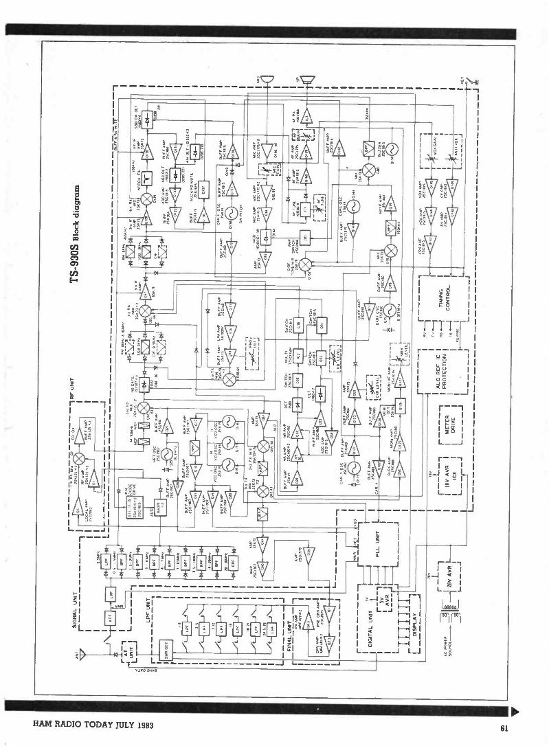
AN
T
2362
1
LUN
ITI
L ISV
IR B
ET
L r
SIG
NA
L U
NIT
r - 111
LPF
UN
IT1
15 0
LPF
11 21
24 5
. M
FIN
AL
UN
IT PA
AM
PM
AP
172
2
Elli
V A
MP
Alg
if 4I
S
ca>
J
PR
E D
Rv
AM
PI
ZS
CZ
015
0 S
MH
Z
LPF
0 5
1551
113
FR
Y B
PF
1S
3AIN
:
.S4B
PF
141
.2
.011
-1 B
PF
1.-4
111-
4
AC
C
r1
Igg
i's-3
A"'
II L
I sill
M.
0203
04
25 2
RF
AM
PP
OP
P75
.120
. 2
11:1
BU
FF
AM
P25
0.75
2
RF
UN
IT
-J
TS
-930
S B
lock
dia
gram
BU
FF
t M
xM
UT
E
OH
12.
1]Z
SA
101
5 2
ZS
C
ear
f* -
1I S
AM
/
9-13
1-1
BP
F
TO
83M
Hz
-04-
1 B
P, 1
14-
AM
PZ
SC
1901
BA
PIN
DIO
DE
DR
IVE
10-
BU
FF
AM
PZ
SC
I901
HE
T O
SC
TS
C19
01
Ton
ina
RF
II 13
.204
2M
IAN
B G
AT
EC
FT
JCF
25K
175
254541.1
A06
263
BU
FF
AM
P2S
C11
60
MK
,
1 B
UF
F A
MP
BU
FF
AM
P35
0110
1C
1
2111
0
7
Cti
Ea
41Z
S Bur
; AM
P25
Ct S
OT
'411
(31
1.4
VC
OS
CC
O O
SC
BUFF AMP
25511
2501
925
519
ZS
CIfO
:14
0.5
BU
FF
AM
P15
C.1
01 AM
P35
.113
4 41
VA
ePA
AM
P35
K/3
AM
P/S
C11
13
DIG
ITA
L U
NIT
';r I
A V
RI
EI IC
NIP
TA
TIIf
l
PLL
UN
IT
I
- J
2113
Tx
MIL
SIN
73
3SK
73
.1
0424
305
5 56
ALC
BU
FF
AM
PN
B A
MP
NB
AM
P25
011
nous
.:Z
SC
1111
3
CA
R
BU
FF
AM
P1S
C46
0A
OC
AM
Pzs
c
1%1
CA
RI
OS
CB
UF
F A
MP
2504
10150460
OIII BU
FF
AM
P25
0160
OE IN
N
Oil
051
16
AM
MH
z 6
M.,
S58
3i.o
u M
I cw
o55
02
Istir
xM
ix15
5
AM
1
353'
1; 3
:4.
2po
Ii14
-176
1041
44-.
5513
Ht
33:0
:315
511
NO
TC
H F
O.'M
P"
065
.nw
iD
r.:w3S
K /3
6615
571
ArW
0121
111
0646
0
I4
BU
FF
AM
PLI
M A
MP
BU
FF
AM
P35
5 T
3T
A23
02P
ZS
C46
0
41 4
1 41
-)44
-`0:
?:
BU
FF
AO
C A
MP
AO
C O
CT
BU
FF
AM
P25
8300
2SC
IIIIS
INN
v25
0360
4311
1 44
CI
411
D22
0 22
1
BU
FF
AC
C &
11I
x M
UT
E25
0111
525
A10
15
1:1>
1111
AM
DE
T .S
ISS
S?
209
21
SS
8 C
M C
ET
1140
14
241
BU
FF
AM
P25
C41
0
DE
T
iN11
0 .1
2
SW
ITC
HM
uL ti
250.415
TC
40III
3P
131
ON
SW
ITC
H2S
CIO
IS
111
IDS
WIT
CH
/SC
Ills
BU
FF
AM
PA
MP
Du-
Citt
-nc4
4
BU
FF
AM
P45
0
444
®51
0o04
BU
FF
AM
PD
E 2
?SC
AN
.0.1
161
..25
0
rgo.
00,2:C46001
035
SW
ITC
HM
OP
S
`NB
LE
ILL
031
I -0C
-1
I CA
RLEVELI
MO
NO
AF
AM
PZ
SA
IOIS
1
Ct&
MO
N!
L_ L
EV
EL!
,
BU
FF
AM
P?S
CA
M
CA
RA
OS
CT
315M
Hz
0151C
AR
. OS
CB
UF
F A
MP
BU
FF
Am
,35515
2SC
Isis
25C
1115
:C>
CM
PIT
CH
MO
DM
C A
MP
MIC
AM
PM
AP
NE
MM
CI 3
02S
AIIP
S2S
CII7
5.
41 1
31 4
114
0A
l
SO
XA
MP
TO
NE
Mix
SW
ITC
H25
5975
020%
01 2
Q
OtT
11.1
1C
IG±
ta,
MIC
AM
P15 /
1.41
C
0146
MT
AF
TU
NE
MB
A.
AF
AM
P?S
AM
.A
F A
FA
P fa
nas
PA
TS
Ci1
/5lu
oixo
li1
11It:
111
13t>
Dr>
AF
L_
L
BU
FF
AM
PC
AR
3 O
SC
2SC
IIII5
?SK
I,
BU
FF
AM
P2S
C46
13
Mix
/SK
I]O
lt
OH
IO
BU
FF
ALA
.Z
SC
OO
L42
1:1;
4555
.12
I X
1SK
21 040
BU
FF
AM
P25
0111
5
EFA
BU
ZZ
ER
25C
1111
5
01 S
O C
)
ISH
z
AC
PO
WE
RIg
r1
SO
UR
CE
28V
AV
R .
r---
--,
1
i:I
ALC
RE
F. I
CI
Ivy
--1
18V
A V
RI
IM
ET
ER
1
__,
__--
----
IP
RO
TE
CT
ION
17.
..__,
....1
CO
NT
RO
LI
ICI
II
DR
IVE
II
II
I--
- -
- -J
'1--
-IG
L. -
-L
r-J
L -
- -
IL
001
AM
P25
C O
HS
VO
X A
MP
VO
L A
MP
44C
040
:1
?SC
UD
SM
CI. 41
Hy
.6-1
Av
AM
PZ
SC
iliS
'403
1:1
"440
. AM
P2S
CII1
S
VO
L G
AIN
AN
TI V
OK
II
---
J

vanced above about setting 6/7, and in-troduce lots of distortion products. Untilthis was realised, one station was aboutto get told he was occupying 50kHzbandwidth on 80 metres - switching offthe blanker solved the problem!
A further row of pushbutton swit-ches control T -F SET (allows momentarylistening on the transmit frequency whenboth VFOs are in use), the IF notch filter(claimed at better than 40dB and effec-tive, it is very critical to tune indicatinga narrow notch), AF TUNE (selects theAF audio filter for CW), and a DIALLOCK facility which disables the tuningknob.
RIT is controlled by two of thesepushbuttons. One selects/deselects thefunction by repeated pushing, and theother is a CLEAR control. A rotary con-trol beneath varies the RIT offset upto ±9.9kHz maximum, a useful rangefor DX-pedition split frequency workingwithout involving the dual VFOs. If anRIT offset has been set, the original fre-quency can be returned by pressing RITagain, but the offset is held anddisplayed - it can be reactivated bypressing the control again. PressingCLEAR either deletes the offset frommemory, or, if RIT is active, resets to thenominal frequency and also clears theoffset.
Further rotary controls set NOTCHFILTER frequency, and AF and RF gain(concentric).
Passband tuning
The remaining controls are con-cerned with the various forms of pass -band tuning and CW receptionfacilities.
CW VBT (CW Variable BandwidthTuning) allows reduction of the band-width in theCW mode, but does not af-fect the centre frequency. The actualbandwidths obtainable depend on thefilter in use. The review rig came withoutany CW filter as such so the SSB filter(2.4kHz) is used. This gives control over2.41(Hz-600Hz bandwidth. If you have aCW filter fitted, then the control allows500Hz-150Hz bandwidth. This control is
also effective in the AM position with thesame bandwidth control!
As it stands the CW received beatnote is around 800Hz, which suits mostpeople. If you want to use a differentpitch then there is a PITCH control,which allows you to alter the pitch to suitand varies the filters centre frequency tomatch. It also adjusts the sidetone fre-quency to be the same as that of thereceived signal.
Effective only in the SSB mode arethe SSB SLOPE TUNE controls(HIGH/LOW) arranged as two indepen-dant concentric controls. One sets theupper edge frequency of the filter, andthe other the lower, so that the band-width can be set to suit the conditions.These controls are easier to use than theYaesu FT -102 equivalents which are fric-tion locked together and very stiff tooperate. Being able to set the bandwidthwith the upper and lower cutoff frequen-cies defined is a very useful operatingaid, especially when as effective as thisversion.
The back panel
Having disposed of the front, wemove to the back, via a small sliderpanel on top which covers the memoryback-up battery compartment, and theVOX controls, plus a calibrator on/offswitch.
The first thing that is verynoticeable is the presence of two coolingfans. One is for the power supply (andthis one comes on a lot even on receive)and the other for the PA. The later hastwo speeds - the fan first comes on at aheatsink temperature of 45°C. If youmanage to get the PA heatsink above 75- 80°C, probably because you have in-sufficient convection cooling, the fanspeeds up, the TX circuits are disabled,and will only be re -enabled when thetemperature has dropped below65-70°C.
Both fans are quiet and unobtrusive,except when the PA one is running atfast speed, although still acceptable andboth are guarded against prying fingers.
Along the lower rear apron, left to
MOPright, are the SO -239 aerial connector,an earth terminal, RX aerial switch (forusing an external receiver rather thanthe TS -930S itself), and the external RXsocket (phono). Output for a transverteris provided (no output level quoted) viaan 8 -pin DIN socket, and for external ac-cessories such as linear amplifier viaanother 8 -pin DIN.
If you have a monitor scope, youcan view the received signal waveformvia the IF OUT jack, taken just beforethe product detector, and if you are go-ing to the USA, you have the usualphone -patch facilities. Of course, theseIN/OUT jacks also enable you to transmittape recordings (of the right kind!), andtake AF output from the rig for recor-ding, SSTV, AFSK etc (at 600 ohms im-pedance).
The remaining connectors are forRTTY keying (low level only - not cur-rent loop), AC power, external speaker(3.5mm) and CW key jack (0.25"). Plusof course a fuse (AC, 4 amps).
Construction
Externally the TS-93QS is a very im-pressive unit to look at, finished in two-tone grey (light case, dark panel) with afaultless finish. The controls are allsmooth and easy to use, with no ex-cessive pressure needed for the swit-ches.
Internally, the standard ofworkmanship is high, with most of thecircuit boards arranged on the under-side. The PA, output filters and PSU areon the top. Some screening of individualsections is provided, which must helptowards eliminating sproggies, as thereare very few to be found. Some adjust-ment points are marked in the manual,for sidetone, monitor and buzzer levels,Mic impedance (high or low) and notchfilter adjust).
As noted earlier, there is little ser-vice info provided if you do want totackle this yourselves, but there maypossibly be another manual available.This is akin to buying Lotus or Ferrariand not being able to get hold of a ser-vice manual!
62 HAM RADIO TODAY JULY 1983

Note that the fans need lubricatingevery six months or so.
Circuit
As with previous reviews, it is notintended to do a full circuit analysis,other than an overview, so as to leavemore space for the on -the -air resultswhich are hopefully of more interest tothe average reader.
The TS -930S uses a quadruple con-version technique for receive and tripleconversion for CW, with IFs at 44.93,8.133MHz, 455 and 100kHz, with the lat-ter only used on receive. All receivedsignals are up -converted to the first if viathe VCO output, which is itself controll-ed in 10Hz steps (and thus sounds vir-tually continous).
The claimed dynamic range of
103:113 (two-tone, 20 metres, 500Hzbandwidth, 0.25uV, S/N 10dB) is notdesigned in by omitting RF amplificationahead of the 1st mixer, as with theFT -102 and others, but by using 2SK125JFETs in a parallel RF amplifier circuit,with similar devices in the 1st mixer,buffer amp, and second mixer in orderto achieve high signal level handlingcapability. The variable bandwidth con-trols use two variable carrier oscillatorsat 8.83 and 8.375MHz.
The notch filter works at the 100kHzIF, with the noise blanker operation tak-ing place at the 2nd IF (8.83MHz) - thisuses a 4 diode switch immediately aheadof the main filters.
The RF output is solid state switchedto achieve full break-in operation onCW, with only a few relays to be heardfor the TX lockout and attenuator swit-ching. The PA is broadband it and theaerial for removal of any spurioussignals. Another bank of nine bandpassfilters is used on receive ahead of the RFamplifier.
The TS -930S on the air
The rig was used over a period of 4weeks on most of the bands available -both transmit and receive - except onthe WARC bands for reasons already ex-plained. Conditions on 10 metres werepoor for the majority of the time so fewcontacts were made on this band. Youwill have to be very careful trying tokeep the power down on Top Band (ifyou bother!). As far as the transmit sidegoes, not one adverse quality report wasreceived, even with the processingwound right up, although a level ofaround 10dB indicated seems aboutbest.
The PA showed no signs of stress ex-cept when a piece of paper had fallenover the rear of the unit, and caused theheatsink to overheat and bring the pro-tection circuits into operation (at leastproving they work). The rig stays
TRIO TS -930S LAB TEST RESULTS
All tests were carried out using the equipmentin upper sideband mode
RECEIVER SECTION
Receiver sensitivity for a measured receiver SINADof 12dB. Voltage quoted as PD
2MHz 0.2uV3.5MHz 0.2uV7MHz 0 22uV14MHz 0 22uV21MHz 0.18u V28MHz 0.18uV29MHz 0.2uV
Test for dynamic range of equipment. The inter -modulation performance was measured by connectingtwo generators through a hybrid combiner. Generator1 was set to 7.051 MHz and generator 2 to 7.101MHz. The equipment was tuned to 7.000MHz.The generator levels were increased until an intermodproduct was observed equivalent to an S4 (2uV)input signal.
The generator output levels required to induce thiswere 14.2mV. This is equivalent to a dynamic rangeof 77dB. The same test was carried out with the noiseblanker switched in. No adverse effect was noted
Susceptibility to internally generated spurious signals.
The aerial input was loaded with a 50 ohm resistivesource and the receiver tuned over its entire rangeand all spurious whistles and birdies noted. All werebelow AGC threshold, ie no meter indication. Thefrequency given was that indicated by the display
498.5kHz4.638MHz4.804MHz6.146MHz8.370MHz8.829MHz9.138MHz9.998MHz
13.634MHz16.745MHz18.179MHz18.440MHz19.998MHz25.119M Hz29.764MHz
The S meter calibration was checked at 7MHz
Meter reading input level dB change
S1 1 luVS3 2 OuVS5 3 8uVS7 lOuVS9 32uVS9+20dB 280uV59+40dB 2mV59+60dB 18mV
TRANSMITTER SECTION
0
5
6
8
10191719
Ham International of Buck -lands Road, Leicester suppliedthe review unit
The engineering tests were car-ried out by Redifusion RadioSystems, Crawley, Sussex
OUR OBSERVATIONS
The practical aspect of the rev-iew conducted by G3WPO showedthat the TS -930S performed im-maculately. As the man said, healmost shed a tear when itwent. I have used the equipmentmyself and confirm that it is a
beautiful and desirable piece ofgear. However the lab test (con-ducted independently and imp-artially) showed up a discrepancybetween perceived and measuredperformance.
In every electrical parameterbar one, the machine showeditself to Justify the praise fromthose who used it. However, themeasured dynamic range fell con-siderably short of the manu-facturer's stated figure of 100dB.We measured 77dB to be precise.It is possible but doubtful that wehave made a measurement error.The manufacturer specified hisfigure at 14MHz, CW, 10dBSINAD. We measured ours at7MHz, SSB, 2uV intermodproduct. After all, 40m at nightis where it counts. Having saidthat this crucial measurement does-n't compare well with an FT -102 (90dB) night-time 40m op-eration didn't show up any nastiesor even mandatory use of theattenuator.
As I said at the beginning, theperceived performance is flawless.
G4JST
Measurements carried out with either a single lkHz tone or two tones of 1100, 1 700HzIntermod products quoted as dB below each tone and harmonic products dB below fund-amental
Frequency power intermod products (3rd, 5th order) harmonics (2nd, 3rd)
1.8MHz 105W3.5MHz 130W7.0MHz 130W14 MHz 135W18 MHz 135W21 MHz 140W24 MHz 140W28 MHz 140W29 MHz 140W
27 3735 4040 4734 3530 3533 3528 3428 31
38 32
40 6058 4760 6370
Blanks indicate that measurements have been limited by analyser range
HAM RADIO TODAY JULY 1983 63
reasonably cool, even after extendedperiods of operation and as notedearlier, the cooling fans are quiet.
Tuning up is of course no problemwith the broadband PA, but a matchingunit is almost a necessity if you are usingany form of multiband antenna. All tun-ing was done at low power (around 10watts) before increasing to full output forfinal tweaking. The presence of theautomatic VSWR meter is of con-siderable assistance here, although I
have some doubt as to the accuracy ofthe actual readings, although the nullseems OK.
On SSB, it is necessary to get theALC reading well up when transmitting- if the meter is only just kicking off thestop you will be losing a lot.of availabledistortion -free power output. Severalstations commented on the noticeable in-crease in received signal strength withthe ALC well into its allowable limits,against a low reading, with no degrada-tion of the signal quality, either on or offfrequency. You can use the MONITORfacility to set up the processor level ef-fectively and convince yourself thatthings sound OK. Power output was vir-tually constant across all the bands, themeter indicating in excess of 100 watts.
One of the joys of this rig is for theCW addict, as the benefits of full break-in working level the semi -break-inmethod (which this rig can also do) along way behind. With full QSK, it ispossible to return to receive between theindividual dots and dashes of thetransmission, allowing the other stationto break-in (just like VOX working onSSB) or alert you to interference on thefrequency. The lack of TX/RX relaysmakes this a very quiet operation andmost enjoyable in practice.
Receive
Most of the subjective evaluation ofthe transceiver was done on receive, andconsidering that you will spend a farlonger period receiving than transmit-ting, it is the more important mode.
The sensitivity of the rig is such thatone need not consider any extra RFamplification, and it is quite feasible tooperate with the attenuator in on thelower bands without realising it.Dynamic range appears to live up to itsclaimed specification, with little sign ofany problem except on 40 metres on oc-casions. The only untoward signs occurwhen the noise blanker is in use, and theblanking level above setting 6 or 7, whenthe dynamic range is greatly reduced,and distortion products become very ap-parent.
Suppression of the static clickswhich abound most days using NB 1 waseffective, and this blanker was usuallyleft on about setting 4 most of the time.Switching it out after a period of useshowed how effective it was.
SelectivitySelectivity from the fitted standard
filters was excellent, and the variouspassband tuning controls did their jobvery effectively. The SSB controls enabl-ed virtually any interfering signal to bereduced or removed completely byvarying the upper and lower filter cut-offfrequencies which appear to be sharp,and in conjunction with the deep notchfilter, anything left within the passbandof the actual signal being received couldbe mostly eliminated. On CW, the VBTcontrol is fairly effective, but thesteepness of the skirts in the narrowerpositions could have been better.Reciprocal mixing from adjacent sta-tions was non-existent unless the stationsthemselves were wide in the first place.
The AGC coped with all signalswell, using SLOW for SSB and FAST forCW. Attack and recovery times wereadequate with little 'pumping' on strongsignals. When an unwanted strongsignal was within the passband of awanted weak signal, it was necessary toswitch the AGC off, and reduce the RFgain to allow proper reception, but thisis not a fault with the rig itself.
Good audio
The audio system is one of the best Ihave heard, with no detectable distor-tion, even at volume levels from the in-ternal speaker way above that possiblewith other rigs. You are unlikely to wantan extension speaker even in a largeroom! The tone of the audio is pleasantand not tiring, although no adjustmentssuch as tone control are provided.
Tuning around
One of the other little extras is ableeper! Well, no modern rig is com-plete without one. This one is not too ob-trusive, and gives a stomachable ut-terance each time any frequency changeis made with the select buttons, the RITis selected or cleared, or the MEMORYbutton pushed.
Using the memories and dual VFOsis fairly easy after a few attempts, andbesides split frequency working, itallows you to jump round bands and fre-quencies keeping an ear on QSOs, pile-ups etc, ready to jump in when the timecomes.
Frequency stability is excellent,with just a slight shift during the first fewminutes after switch on, but withinspecification. The 10Hz step rate of theVFO makes you think you have con-tinuous tuning - you can only justdetect the steps if you listen carefully.The only slight criticism is a clickingnoise every even 2kHz as you tune rapid-ly, more apparent on AM than any othermode. The nicely balanced tuningmechanism is a treat compared to some
rigs with stiff controls, and although youcan spin the dial effortlessly, it stops witha positive action, then only needs a lighttouch to get things just right.
General coveragereceive
Although I have no particular in-terest in general Short Wave DXing, thegeneral coverage mode on receivemakes this rig a natural for the purpose.You can hop around in 1MHz steps easi-ly, using the amateur band buttons forrapid QSY near the band you want. In-cidentally, continual pressing theUP/DOWN 1MHz buttons does not resultin stepping, just a continuous bleep.
On AM, many DX stations werecopied on the MW band, and thevariable selectivity sorted them out atnight with no problem. The reproduc-tion quality of broadcast stations wasadequate, although if you want to relaxand use the RX for Radio 2, 3, or 4, youcould do with a better speaker. It will godown to 100kHz, although the manualsays 150kHz.
For frequency checking all theStandard Frequency and TimeTransmissions are available of course.The receiver as supplied checked outaccurately (within the digital readoutresolution) on WWV and other transmis-sions.
Conclusions
In my opinion there is no doubt thatthis transceiver is the best to passthrough the shack so far. It is effortless touse and importantly, very quiet in oper-tion with no RX/TX relay clatter. It hasall the facilities you are likely to wantand these all seem to perform as re-quired, the only possible exception be-ing the noise blanker, and even then on-ly when blanking level is set high.
For the CW user, it is one of only afew rigs designed with CW in mind, andwith the addition of one of the optionalCW filters should please all but thosewho don't want to pay for SSB facilities.
I would criticise the manual in termsof lack of servicing info, but there again,the transceiver is a complex machine,and not suited to anything but experttwiddling. The lack of FM facilities mayannoy some, especially if you want to useit for VHF transverting.
Bearing in mind the warnings aboutkeeping the VSWR down, there appearto be no problems on transmit, and veryfew to receive.
If you want to spend the money,then if the review sample is represen-tative, you should be very happy withyour choice for some time to come. Ished a tear when it had to go.(Our thanks to Ham International for theloan of the review sample - Ed.)
64 HAM RADIO TODAY JULY 1983
O HAM RADIO TODAY MORSE COURSE offers the mosteffective route yet to your Class A amateur licence
Professionally produced for HAM RADIO TODAY by ShirleyHesketh G4HES and Ron Ray G3NCL, this advanced interactivelearning system makes use of the stereo cassette format toprovide tuition to the 12wpm test standard
With its carefully designed structure, we think that theHRT MORSE COURSE is more effective than either morseclasses or electronic morse generators
Based on TWO C-60 cassettes, it offers the controlled promptingso necessary for the initial stages of morse tuition, followed bycarefully paced test material to bring the student up to speed.Full tuition notes are provided with the cassettes
To receive your MORSE COURSE simply senda cheque or P10 for £11.45 (inclusive of VAT and P&P) payableto Argus Specialist Publications Ltd, 145 Charing Cross Road,London WC2 OEE. Mark the envelope 'HRT MORSE COURSE'.
E1000.00INSTANTCREDITAVAIL ABLE
FOR AMATEUR, PMRAND MARINE EQUIPMENT
Advice is free-- please ring
for famous namesICOM. FDK. AZDEN. DAVTREND.STANDARD. WELZ. COMMUNIQUE.ETC. ETC. HF. VHF AND UHF.NEW AND SECOND HANDSALTFORD (02217) 2402.24 HOUR ANSWERING SERVICE.CLOSED ALL DAY MONDAYS.
Staff:- G3NXU. G3XOD. G8DPH
6 GOLF CLUB LANE, SALTFORD, BRISTOL BS18 3A A
FORTOP LTD, FIRST AND BESTFOR FAST SCAN TV.
a
The TV? 435/R TV transceiver allows transmission and recep-tion of 70cms Amateur TV signals. Features. 15 watts mm PeakSynch RF output, Bandwidth limiting filter, switchable modulationsense, video inputs and carrier frequencies. High performanceRX converter built in. Requires aerial. 12 volts power, videosource (camera etc) and stand UHF TV set to complete fast scanAmateur TV station. £169.50 plus 12.56 P&P.
For further details please write or ring to:FORTOP LTD, 13 Cotelaili Rood, Warrington, Stoke on Trent, tail
Ash Bank (07$ 1310) 2007
PROP A L BAILEY G3WPO 1WPO COMMUNICATIONC
KITS KITS KITSANNOUNCING A CW OR CW/SSB HIGH PERFORMANCE TRANSCEIVERKIT - as currently being described in Ham Radio Today. Full OSK CW. 5 or 50Watts, All bands, Woodpecker blanker. 12v operation etc etc. Main i.f. pcb kitnow available at £69.50 inc. Very comprehensive detail for allmodules to suityour constructional level. Total cost for all options will be around £250, less forCW alone. or only some bands.HAVE YOU BUILT THE DSB8O YET? Over 100 of these little transceiverssold - see previous ads for more details 80 or 160 Meter version now avail-able as kits. Both at E37.45 Inc for full pcb kit with reduction drive. VFOcapacitor etc.
ACTIVE AUDIO FILTER - 7 position switchable unit for SSB and CW. Lowlevel AF in and out. +12v operation. Great with the DSB80/160 or the HPTransceiver (see July Ham Radio Todayl. Full kit with rotary switch only E15.45IncHF FOR VHF'era -a FIRST with a 2 metre to 20/1 5/10 metre TRANSVER-TER KIT. To be described in August Ham Radio Today by G4DHF. Use thatexpensive VHF Multimode with all its facilities as a driver with RF input from0.3 to 10 watts at VHF. 3 watts pep output HF (of drive a linear with this to400W) +12v operation. Complete Kit 12 pcbs) only £61.00 inc excluding con-version crystals which are extra at £4.00 each 13 required max - state whichbands wanted from 20/15/101.(Kit available July to coincide with article - beat the rush with an ordernowl)2 METRE FM RECEIVER - our popular kit costs ONLY £30.65 including 520crystal. 6 channel max. <0.2V sensitivity. Helical RF filter, 10.7MHz roofingfilter. 455kHz ceramic filter. Prewound inductors. +12v dc operation.CAPACITY ADDON UNIT (Sept 82/May 83 RadComl - very popular unit forturning your DFM into a Digital Capacitance meter. Kit with case onlyL13.65 inc.VHF PRESCALER - lots of these sold at only £5.49 inc for the kit including,.asel Divide by 10 to 150MHz (usually 200MHz+12v operation.RX130 ATU - as in Aug 82 RadCom. SWI or ORP Antenna Matching Unit. Kitcomplete with case, capacitors, toroid, wire, knobs etc at £25.32 inc.IAMBIC KEYER - ready built and cased keyer for PP3 or +12v use. Solidstate auto polarity keying. Needs a paddle such as Bencher etc. ONLY1:20.65 inc2 TONE OSCILLATOR - useful unit for checking out your SSB rig. Readybuilt and cased. Switchable tones. priced at £18.65 inc.ALSO - specialised equipment for the Blind - write for details.All prices include VAT/ Post. Allow 1-4 weecs for delivery if not ex -stock, we'll!el you know anyway if over 1 week. All kits complete including pots, wire etcand detailed instructions. RS COMPONENTS range also available to order.MAIL ORDER ONLY - CASH WITH ORDER. EXPORT no problem. SAE formore details/enquiries please
20 FARNHAM AVENUE HASSOCKS WEST SUSSEX BN6 8NS
HAM RADIO TODAY JULY 1983 es

Active SSB/CWThose of you who have built theDSB80 transceiver featured in theMarch issue will hopefully have aneat little transceiver with excellentsensitivity for double sideband andCW use. The one area where animprovement can be made is with theselectivity. Being direct conversion,the receiver bandwidth is that of theaudio stages - around ±6kHz. On asparsely populated band this is not amajor problem, but after dark thelevel of activity, both commercialand amateur requires a means ofreducing the bandwidth to improvecopy.
The answer for a directconversion receiver, whereconstructing a variable frequencycrystal filter is something of aninsurmountable problem, is an audiofilter. To take advantage of moderntechnology an active design, ratherthan passive, was chosen. This hasthe constructional advantage of notrequiring any inductors, just Rs andCs and a few op -amps, so that size iskept to a minimum. It requires noalignment, and with this design, youcan switch just the bandwidths mostsuited for your applications, or haveall the selectivity options switchselectable.
The filter can be used with theDSB80, or any other directconversion receiver, and is designedto be placed immediately before theAF power amplifier stage of the RX,or some other suitable low-level AFpoint. There is no reason why a singleIC AF amplifier could not be addedfor driving a low impedance speakermaking the unit self contained. Itoperates off +12V DC and consumesabout 15mA.
This project is also intended to beused in conjunction with the HFtransceiver design started in thisissue, and will provide the main CWselectivity for the basic transceiver.As with the transceiver, a kit of partsthe PCB will be made available toconstructors. The assembly is notdifficult and the project is suitable forall levels of contructor.
Circuit
The design is split into two basic
PROJECT
This switch selectableactive audio filter notonly forms part of theProject S2 transceiver,
but can be used toimprove many other
rigs as well.sections - that for SSB and that forCW use.
For SSB, a bandpasscharacteristic is required, with a lowcut-off point around 300Hz, belowwhich received audio contributesnothing to the intelligibility of thesignal, and a high cut-off between1.5 and 3kHz. If greater than 3kHzyou are receiving unwantedinterference and no enhancement ofthe signal, while below 1.5kHz theintelligibility suffers.
Unfortunately it is not possible todesign an active filter circuit whichcan accommodate both these highand low pass bandpass requirementsin one circuit while still maintaininga flat passband. Hence it is necessaryto split the filtering into separatehigh- and low-pass sections.
Before the active filters, a bufferamplifier IC1 is used to isolate thefilter input proper (IC2 on) from theAF input, as varying loading on theinput to 102 would affect theresponse characteristics. A 741 op -amp is used as an inverting amplifier,with R6 setting the overall gain.
For most applications a unitygain configuration would be neededin which case R6 would be 2k2. Ifsome additional gain is required inthe system, the value of this can beincreased to suit. For the DSB80, thiscan usefully be increased to 15k. Thiswill be found especially helpfulduring the daytime when signalstend to be weaker. Point C allowsdirect connection to the buffer ampoutput if needed without any filteringhaving been introduced.
C 1 provides DC isolation fromthe audio circuitry being used.
Supply rails
To avoid the need for bothpositive and negative supply rails,where the non -inverting inputs wouldbe taken to the negative rail, the non -inverting inputs to all op -amps arebiased to half the positive supply railvoltage via a resistive divider (R2/4for IC1), creating a virtual zerovoltage at +6V, and allowing signalsto swing either side of this as though
Fig. 1 Wiring the filter into the SDB80
HAM RADIO TODAY JULY 1983

filtby Tony Bailey G3WPO
there were two supply rails at + and-6V.
The remainder of the circuitryutilises LF353 dual BIFET op -ampsfor low noise contribution. The firstsection of IC1 is configured as a highpass filter, with a -6dB cut-off at300Hz, which reduces all signalsbelow this frequency, but passesthose above virtually unattenuated.
All the filter components weredesigned via a computer program toallow selection of values close topreferred value components. In somecases non-standad values ofcapacitors and resistors are needed,however, to maintain the requiredcharacteristics, and the parts listshows how these can be synthesisedby series or parallel connection oftwo other values. It is important thatthe tolerances of the components areas specified - using normal carbonfilm resistors will result in inferiorperformance, with non -specified cut-off frequencies, varying gain, andwrong Q values. The capacitorsshould be 10% or better types - ifyou have a capacitance meter, theycan be selected for best value.
The first of the low-pass sections
dB
30
1663 t 2 2 26 )0 34 I I
Fig. 2 Measured filter response
follows in IC2b, with a nominal -6dBpoint of 2.2kHz. This will removemost of the high frequency chatterfrom a direct conversion receiver atoutput D, without impairingreproduced quality at all, and alsoreduce any hiss which may have beenintroduced by the receiver's IF orearly audio stages. Signals higherthan 2.2kHz are attenuatedprogressively as the frequencyincreases, those below are notaffected.
To reduce the bandwidth slightlyif needed to a nominal -6dB point of2.0kHz, IC3a is cascaded with IC2b,improving the rolloff on the high cut-off side in the process. Audiointelligibility will still be satisfactoryhowever. Further reduction inbandwidth is by another cascadedstage (IC3b), with a nominal cut-off of1.5kHz. This is useful when there is alot of interference about, but thereceived audio bandwidth is now alittle narrow and the signal maysound restricted. With three filtersnow cascaded, cut-off on the highfrequency side is very good. The1.5kHz position is also useful fortuning around on CW.
CW
For CW use, advantage is takenof the SSB filtering by passing allsignals through the cascaded high -
and low-pass sections prior to thenarrowband CW filtering.
Filters for CW, with muchnarrower bandwidths possible,require a different approach to thatfor SSB. There are two schools ofthought as to the type of filterrequired with some people preferringa similar type of filter to that of SSB ie.with a narrow but flat passband, sothat some idea of activity near to thewanted frequency can be obtainedwhile operating. This does have thedisadvantage that signals very close
in pitch to the wanted one cannot beeliminated very well.
The other approach is to have a'peeked' passband. The problem inthe past has been that to achieve verysteep slopes to the skirts, the filter hasto have a fairly high Q of around 10 orhigher, which causes the filter tomomentarily break into oscillation,or 'ring' as signals pass through it,with a very sharp response which canbe tiring to listen to for long periods.This can be avoided by designing in alow enough Q to prevent thishappening, while still maintainingadequate stopband rejection whenusing cascaded filter sections.
For the peak response sectionsused here, the Q is fixed at 4.5, withjust sufficient filter gain in each stageto overcome the loss of that stage, atthe fixed peak frequency of 800Hz.The -3dB bandwidth for one sectionis 170Hz.
The four cascaded sections ofIC4a/b and IC5a/b are eachidentical (except for the inputresistor which sets the gain withoutunduly affecting the peak response),with outputs available from eachstage if required. With all foursections in use (output J) the responseis very sharp, with very littletendency to ring if interference pulseare present.
Final output from the filter istaken via C31/R40 to isolate any ofthe outputs with dc voltages presentfrom the subsequent audio circuitry.
Contruction
The construction of the filter isnot particularly critical, either PCBor Veroboard type layouts aresatisfactory. Leads should be keptshort and all connections to the inputand output sockets, and the switch,must be made with screened audiolead. The power supply used to drivethe filter needs to be well smoothed. If
Irj FLT
41Z:
:13? :FZEtoci::L0.311cPY
°`C°
NOTE. Dotted line from 2nd IC on left is trackside wire link
Fig. 3 Printed circuit layout for active filter - track side
1HAM RADIO TODAY JULY 1983

hum problems are experienced,extra decoupling via a 100 ohmresistor and 100µF capacitor on the+12V line to the filter would beneeded. This extra decoupling would
also be required if the power leadsfeeding the unit are very long.
If you are using the ready madePCB, the following order ofconstruction is advised:
Table 1 Component list
RI, 3R2, 4, 7, 8, 25, 26R5, 12, 29, 40, 41, 42R6R9, 28, 32, 35, 38R10
2k2 5%27k 5%56R 5%2k2 5%/ 15k 5% (see text)2k2 2%9k1 2% (8k2 + 1k)
1 100k 2%R13, 14, 16, 17, 18, 20, 21, 22, 24 10k2%R15, 19, 23 20k 2%R27 68k 2%R30, 33, 36, 39 180k 2%R31, 34, 37 82k2%
All resistors marked 2% should be 2% or 1% tolerance metal film types.Those marked 5% can be 5% tolerance or better carbon film.
Cl, 2, 3, 4, 5, 10, 20, 21, 2431, 32, 33C6, 7, 9C8, 12C11C13, 19C14, 18C15C16C17C22, 23, 25, 26, 27, 28, 29, 30
IC1IC2, 3, 4, 5
Also required:
10g.4/ 16V radial electrolytic27n (22n+4n7) mylar12n (10n+2n2) mylar15n (10n+4n7) mylar2n2 mylar22n mylar18n (10n+6n8) mylar1n5 polystyrene33n mylar10n mylar
741N (8 pin DIL)LF353N
15 lnim PCB connection pinsScreened audio cablePCB1 -pole 8 -way switch (if all positions used)
The PCB and complete set of parts including a rotary switch is availablefrom WPO Communications for £15.45 inc. VAT & p&p.
Table 2 Voltage check chart
All voltages measured with highimpedance digital voltmeter, no AFinput.
PIN ICI IC2/3/41 nc 6.1 nc = no
connection2 6.1 6.13 6.1 6.14 0 05 nc 6.16 6.1 6.17 11.9 6.18 nc 12.0
1. Insert lmm PCB connectionpins through all larger pads from theunderside and solder into place.
2. Following the layout andparts list carefully, insert and solderall the resistors, making sure you usemetal oxide 2% types wherespecified. The 9.1k resistor can be8.2k and 1k in series (the PCB allowsfor this).
3. Insert and solder all thecapacitors, keeping the bodies asclose to the board as possible. Againseveral capacitors may be needed insome places to make up the value -these are designated 'a' and 'b' on thelayout and values are given for eachin the parts list. Make sure thepolarity of the electrolytics is correct.
4. Finally insert and solder the 4ICs, with the pin 1 identifier correctlyplaced. When soldering, be carefulnot to bridge the pads.
5. Carefully inspect the PCB forsolder bridges etc, before applyingpower.
No alignment is required so itshould work first time. If it doesn't, tryto isolate the stage which isn'tworking first by trying each output inturn. Then have a look at thecomponents to see if any values arewrong. The voltage check chart willbe of help here, but allow for the factthat there will be some variations dueto component tolerances.
0
10
dB
20
20
40
0
10
20
dl
30
ao
800 200
Theoretical respons of 1 CW peak section only
KO 1000 1400 1800 2200Hz
603 1000 14.1:0 1800Hz
CW responseIteseeded with see
noo
Fig. 4 Frequency responseof CW filter sections
68 HAM RADIO TODAY JULY 1983

A R2CI
JVV\e- R9 C7R3 R4 b t a b C11
Li R13
C8
a
R
C5
R6 C a-A.A,Ar--ee
0 .- FAIAA1-11
-/NAA.--
14R C12 L K R21a V
[11) l0 C C17c
R15a
R19'V ti
D.14 II-rC13
R12 d\A-4- iN. "ffiR17 R18 R10-. W C32 R7C10 --H41
C4 R31
R28--AAAr-
C25GR30
C26 C28 R35
H
elR36
C27
C21
OR37
C29
iC301R39
R38J R25
N.B Capacitors marked a and b are paralleled on p c b. to make up value shown on circuit diagram,=Connection
Unlettered connection pins are earthActive audio titter -Component layout
Fig. 5 Layout of components on PCB
Avoid mounting the unit near toany AC mains supply or AC -carryingleads. If you are going to use it as a'standalone' unit with an additionalAF amplifier, the input, if driven fromthe speaker or headphone output ofyour receiver will need to have itsinput impedance reduced - connecta 4.7 ohm 1 or 2 watt resistor betweenpoint A and ground.
Use with Project S2transceiver
As mentioned earlier, the gaincan be varied by changing the valueof R6. For the HF transceiver project,R6 should be 2.2k for unity gain. AsIC2b (the 2.2kHz low-pass section) is
somewhat superfluous with thisdesign which already uses a 2.2kHzSSB filter, it can usefully have thecomponent values changes to thesame as IC3a (ie. C11=.022i.4F,C12=.018µF and C13= .0015µF).This gives an additional 2.0kHz low-pass section in cascade which willimprove the skirt rejection stillfurther.
Using with the DSB80
When used with the DSB80, theunit can be mounted behind the mainPCB with the input at the left-handside of the board. The switch forSSB/CW on the transceiver wasspecified as a double -pole
changeover type - this was toaccomodate the switching of thisfilter. It is suggested that the 2.0kHzbandpass output is wired for the SSBposition, and one of the H, I or Ioutputs for CW, depending on yourpreference.
If you want more positionsavailable, then a rotary switch will berequired. If the digital display of theDSB80 is not being used then theswitch can be mounted on the frontpanel (don't forget to use screenedleads), otherwise it will have to go onthe back as there isn't much roomelsewhere. The drawing shows how toconnect up the filter with the DSB80as a two position unit only.
CI3-1
iPu 10p
6217k
C3 10p
65 a96 R7 270
Buller amps fie,
R25
C1110p
12
CS C6 C7
I0 27n 2" 27n
R9 RIO202 901
C
10pRR27k
RI2 56
'OpRI5200
RIG
-D
101, 210200
017 618 R20
Ok 100 100
2 LF 351 CI0 CIS
1220 Tin
0,90 pass CO. pass3000: 2 2001 2kHz
C16 R23 2 00 ...SP.,105
621 622 620
LOW pass
10
ria Lb 353, 4.C17T33n
10k
1.18inn
Low passSOH:
26535
10p
27 R29 56
C23
qr 830
180k
927 C22
660 lOn
628 202
R16274
r
10u
R31
824
LF 35Y 6
800/4,peakCW1
C26
C25
zan R
lOn
202
S
'60k
80000peakCW2
830
82
Ly 35 ; 35
C27
C28
k2
fik, 56
36
180
ICS°
8000:peakCW3
Fig 6. Active audio filter circuit
637
C29-II-in R
C 0
820 I lOn
1121F35 638 62
800HzpeakCWZ.
160
use
D C
F
H
12v
C3I 10p
R4.0156
LL- CIulpu I
HAM RADIO TODAY JULY 1983 69

Alif01111111GUIDEAVON
6 GOLF CLUBLANE,
SALTFORD,BRISTOL
Tel: 02217 2402Open Tues Sat 9am 913,6
Close Mondays
Radio CommunicationsAmateur P M R Mane
12 li Pf111111VWFll 0000 BRISTOL. BSS oTJ
CAMBRIDGESHIREWISBECH AMATEUR
RADIO 131R -.TA,20-21 Norfolk St., \Vv
WisbechTel: 0945-581099. Open: Mon -Sat 9.6HP facilities. Part exchange welcome.
CHESHIRE
r-lAtiMitle&AGA a CO .r.irrcii58-62 Lower Hillgate. Stockport
Tel. 061-480 4872 Open: Mon & Wed 9.6late nights Tues & Fri 9-7pm. Sat 9-5.30.
Closed ThursYaesu. Sornmerkamp. Diawa. Jaybeam. Kenpro.
Weitz, Datong
DEVON
AMATEUR EQUIPMENTIN THE SOUTH WEST
Appointed YAESU & ICUM denim Full binge stockedAncillary equipment by MICf0WilVe Modules. Mittel,ORAL. Datony eli- Aerials by Joylieitm. TET. Hy -Grain& 0 Whip
Reg Ward (G2BSW) & Co LtdAxminster, EX13 SDP. Tel: 0297 33163
HAMPSHIRE
FARNBOROUGHCOMMUNICATIONS97 Osborne Rd, North Camp,
Farnborough. Tel. 0252-518009Open: 6 days 10-6
Yaesu, !corn, FDKs, Mosley aerials, Jaybeams,G Whips
r
Tel. No.Open Hrs:
Contact (Office Use Only):
FOR YOUR BUSINESS TO BEINCLUDED, CALL
SHEILA OR JAN ON01-437 1002
189 London Rd., North End,Portsmouth. Tel (0705) 662145
Stockist of YAESU, TRIO. TONNA, ICOM,FDK, JAYBEAM
Barclaycard 8 Access. HP 8 PX welcome
KENT
Thanet cm wontElectronics143 Recular Rd., Herne Bay
Tel. 02273-63859Open: Mon -Fri 9-5.30, Sat 9-12.30
(Closed for lunch 1-2)
LANCASHIRE
231 Chorley Rd., SwintonGreater Manchester.
Tel: 061-793-1010Open. 7 days a week.
TRIO, YAESU. ICOM, GWHIP
AERIAL BOOSTERSTrebles incoming weak signal
E111 - for VHF/FM radio; B45 - for UHFtelevision
Next to the set fitting. SAE for leaflets. E7Electronic Mail Order Ltd,
62 Bridge Street, Ramsbottom, Lancs BLO9AGH
YOUR RIG IN OUR THE YAESU EXPERTS CONSULTHANDS G3LLL
Sales Dems & Repairs 4- Mod Kits
HOLDINGS LTD
39-41 Mincing La, BlackburnTel: (0254) 59595
CLOSED THURSDAYS
ISHERWOODSELECTRONICSHozier Street, Blackburn
Tel. 0254-57616Open: Mon -Fri 9-5, Sat 10-1
An Aladdin's Cave of Components
LEICESTERSHIRE
20-28 BRAUNSTON GATE,LEICESTER. TEL: 563293
Open: Mon -Sat 9.00am to 5.30pm
LONDON
THE CENTRE10 MERTON PARK PARADE,
KINGSTON ROAD, SW19Tel: 01-543 5150
Open, 6 days 9am-6pm (late night Weds until 8pml
DAVEMICK
G8SYGG6LHL
The Enfield EmporiumAMATEUR RADIO
Hours Mon to Sat 9-6. Late Friday 9-8. Sun mom 10-1
281 Hertford Road, Edmonton N9Tel: 01-804 0128
lee Electronics Ltd
400 Edgware Rd, W2Tel: 01-723 5521
Open Mon -Fri 9.30-5 30Thurs 9 30-1pm
THE MARINE ELECTRONIC CO LTD1-4 Swan Mead, SE1 4SY. Tel 01-237 3474
Open: Mon -Fri 10am-5pmCommunications Equipment for the
Professional and EnthusiastCallers by appointment only
Please include my business details in the next available issue of Ham Radio Today
Business Name:#4111
MIN
Address: II 0°°N°am 10
Post to: Emporium Guide, Ham Radio Today, 146 Charing Cross Rd., London WC2H OEEL.70
-JHAM RADIO TODAY JULY 1983

11111%1111.1611111EW. MIDLANDS
DEWSBURY ELECTRONICS +
176 Lower High St, STOURBRIDGETel: (0384) 390063
Open: 9.30-5.15.Closed Thurs. Et Sun.ACCESS/BARCLAYCARD
HEWARD'S HOMESTORES LTD. (Est. 1963)822/4 Kingstanding Rd., Birmingham
544 9RT. Tel. 021-354 2083G4RJM with 38 years in The Radio Trade
Ham Equipment urgently wanted'Open: Mon -Sat 9-8
NORFOLK
Eastern Communications
:4 \36 Cattle tlarket StreetAI/Rif/Cif
OMNI: MOM - SAT1040 - .0. N0603)667189667189/MAIL ORDER
ic Om]
SCOTLAND
AXDON32 Athol! Street, Perth
Tel. 0738-23753. Open: 8 daysICOM, TONA, TONG. RSGB Books. Maps
log books. Full range of componentsMail order available - send for price list.
JAYCEE ELECTRONICSJOHN GM3OPW20 Woodside Way. Glenrothes, Fife KV75DFi
Tel: 0692 758982Open Tues-Sat 9-5
andlny secondhand Itawpment m stock Full range of TRIOgoodies Jaybeam - Microwave Nodules - EAR
SUSSEXs°u'"Dc`:':\ 40 TERMINUS RD (oPP.
EASTBOURNE RailwayTel:103231 633351 Stn.)
Open: Mon -Sat 10-6 (Closed Tues)Stockists of: Yaesu, Trio, Tonna, FDK etc +secondhand and es -Government equipment in
stock
Pit) 010
P nifi ELECTRONICP. SERVICES2 ALEXANDER DRIVE. HESWALL, WIRRAL, MERSEYSIDE. L61 6XT
Telephone, 051-342 4443. Telex: 627371
PRICES EXCLUDE VAT-U.K. CUSTOMERS PLEASE ADD 15% VAT
CRYSTALS MANUFACTURED TO ORDER TO AMATEUR SPECIFICATION6 to 9.999khz HC13r U10 to 19.99kHz HC13 U20 to 29.99kHz HC13 U
E32.80E31.0
123.08
1.5 to 2.59MHz (fund) HC6. U2.6 to 21 MHz (fund) HC6 /U3.4 to 3.99MHz (fund) HC18 & 25/U
£5.36E4.87[6.75
30 to 59.99kHz 14C13 U £21.73 4 to 5.99MHz (fund) HC18 & 25/U E5.3660 to 79.99kHz HC13 U E15.69 6 to 21MHz (fund) HC6, 18 & 25/U £4.8780 to 99.99kHz HC13, U (13.08 21 to 25MHz (fund) HC6, 18 & 25/U 17.31100 to 149.9kHz HC13 U E11.32 25 to 28MHz (fund) HC6. 18 & 25,'U f9.00150 to 159.9kHz HC6 U E11.32 18 to 63MHz 13 71 HC6. 18 Ef 25/U E4.87160 to 399.9kHz £7.83 60 to 105MHz 15 0,T1 HC6, 18 & 25/U E5.61400 to 499.9kHz HC6 U E7.00 105 to 125MHz 15 0, 1.1 HCI8 Et 25 E8.44500 to 799 .9 k Hz HC6 U E7.83 125 to 147MHz 17 0/71 HC18 & 25/U E11.25800 to 999.9kHz HC6 'U (11.01 147 to 175MHz 19 0'71 HC18 & 25/U £12.661.0 to 1.499MHz HC6. U 171.25 175 to 250MHz 19 0/71 HC18 & 25/U £13.50TOLERANCES: Up to 800kHz - Total tolerances = 100pm 0°C to + 70°C
Over 800kHz Adj. tot. = 20ppm, Temp. tol 30ppm - 10°C to +60°CUnless otherwise specified fundamentals will be supplied to 30pf circuit conditions andovertones to series resonance.DELIVERY: 1MHz to 105MHz 4.6 weeks, other frequencies 6.8 weeks. Prices shown arefor "one off" to our standard amateur specifications, closer tolerances are available. Please sendus details of your requirements.
COMMERCIAL AND PROFESSIONAL CRYSTALSNEW FASTER SERVICE
We are now supplying crystals to most commercial and MIL specifications in the range 1MHz to60MHz, ordered in small quantities. within 2; weeks AT NO EXTRA CHARGE. We also have aneven faster EXPRESS SERVICE for that very urgent order. We can also supply crystals forcommercial applications e.g. Microprocessor, TV etc at very competitive prices. Let us know yourneeds and we will send a quote by return, alternatively telephone or telex our Sales EngineerMr Norcliffe who is normally available in the office for technical enquiries between 4.30 and6 30 p.m.
DOUBLE BALANCED MIXERWe are now stocking two new double balanced mixers which are pin compatible with both theM0108 we used to stock and also the SBL 1. but have much superior specifications covering500kHz. to 500MHz. The M8 is hermetically sealed @ E7.83The M18 is non -hermetically sealed @ E6.09
4 METRE, 2 METRE AND 7 CENTIMETRE STOCK CRYSTALSWe stock crystals for 70 26MHz on dm On 2m we stock RO thru R8 and S18 thru 924. For 70cmwe have RBO thru RBI 5 plus SUS. SU18 & SU20. For lull details of the above stock crystals plusdetails of our Converter. Marker and Alternative IF crystals, crystal sockets and our AERIALRANGE see April, 1983 Radio Communication, page 294 or send SAE to the above address.
TYNE 8- WEAR
ADI'mva 1=1 LYtTWO NICS "AweOmer °MOM]. hoth
129 Chillingham Rd, Newcastle-upon-TyneTel: 0632 761002
Open: Tues-Sat 10am-6pm
YORKSHIRE4 Cross Church St, Huddersfield Tel:
Open 6 days 9-5.30. 0484 20774
[11.11
Closed Weds. Thurs 9am-80mG4MH Mini Beam
Always a good selector, of new & 2nd nand equipment o stock'
Amateur Radio Shop
0/SCOVIER THE WORLD WITH AMATELR RADIO FROM
L=4`.';VT'"""*"%'52"`- = Ihe PROMSSIOSIALS' °P"1,. -coo -oar
o- oar
TRIO ICOM YAESUUFOS AMATEUR RADIO Met ORDERe Mnvor.f DEM OPEN NON -Fe,60 CREME ROAD MF An1.10011/051. Map If , awn. I In. - I,.OPFIMSI-I MADE RAIE:3 LAP PRODUCTS
MAIL ORDER PROTECTION SCHEMEIf you order goods from Mail Order Advertisers in thismagazine and pay by post in advance of delivery, thispublication will consider you for compensation if theadvertiser should become insolvent or bankrupt,provided:
1. You have not received the goods or had your moneyreturned; and
2. You write to the publisher of this publication explain-ing the position not earlier than 28 days from the dayyou sent your order and not later than 2 months fromthat day.
Please do not wait until the last moment to inform us.When you write, we will tell you how to make your claimand what evidence of payment is required.We guarantee to meet claims from readers made inaccordance with the above procedure as soon aspossible after the advertiser has been declared bankruptor insolvent to a limit of £1,800 per annum for any oneadvertiser, so affected, and up to £5,400 p.a. in respect ofall insolvent advertisers. Claims may be paid for higheramounts, or when the above procedures have not beencomplied with, at the discretion of this publication, butwe do not guarantee to do so in view of the need to setsome limit to this commitment and to learn quickly ofreader's difficulties.This guarantee covers only advance payment sent indirect response to an advertisement in this magazine(not, for example, payments made in response to cata-logues, etc, received as a result of answering such
advertisements):
CLASSIFIED ADVERTISEMENTS ARE EXCLUDED.
HAM RADIO TODAY JULY 1983 71

HAM RADIO TODAY CLASSIFIEDLineage:30p per word (minimum 15 words)Semi Display: (minimum 2 cms)£5.50 per single column centimetreRing for information on series bookings/discountsAll advertisements in this section must be prepaid.Advertisements are accepted subject to the terms andconditions printed on the advertisement rate card (available on request)
FOR SALE
LIST -A -RIGThe daily advertiser for all amateur radio enthusiasts.For your free copy simply send two first class postagestamps to List -A -Rig (HR), 65 Cecil Avenue,Hornchurch, Essex.
G3 RCQ ELECTRONICSAmateur radio equipment bought, sold, exchanged.Tel: Hornchurch 55733, evenings 6/9 pm andweekends.
2 METER SSB Transceiversfrom £138. Full range includ-ing ICOM, TRIO, YAESU,ASDEN, ETC. Credit facilities.Guilford CB, 0483 574434YAESU CPU -2500R TRANS-CEIVER with keyboard Mic andC.P.V. GP -144W Aerial, SWR/Power Meter for 2 meters. Allnew never used £300. Thirsk24986.
KITS
SUSSEX MOBILE RALLY. Aday by the sea with the familyfor £1. Brighton Raceground.17th July. 10.30 am - 5.00 prn.Free Car Parking. Good cater-ing under cover.
01-437 1002EXT 204Send your requirements to:Julie Bates.ASP Ltd.,145 Charing Cross Road,London WC2H OEF
CARDS, STICKERS, BADGES
FED UP with being mistakenfor "Rubber Duck?" Our twocolour plastic car stickers say"No, it's not CB. it's amateurradio!" 60p plus 15p P&P, R.C.Davis, 21 Denton Drive,Brighton, BN1 8LR
LISTENER & OSL CARDSQuality printing on Coloured andWhite Gloss Card at competitveprices. SAE for samples S.M.Tatham "Woodside", OrchardWay, Fontwell, Arundell, WestSussex.
FOR ALL YOURCLASSIFIED
REQUIREMENTSPHONE
ASP LTD01 437 1002 extn 204
ENGRAVED LAPEL BADGESLapel badges with electrically weldedsafety clip, most Colours available,Example: Club Badge. club name, per-sonal name. callsign, with or withoutRSGB logo - 1 to 10 badges 85peach. 10 and above 80p each inc P&P.Please use block capitals for all orders,cash with order, orders dispatched byreturn first class post.Club Secretaries please send for sample
DARFIELD ENGRAVING SERVICES39 Cliff Road, Garfield. Barnsley,
S. Yorks S73 9HRTel: Barnsley (0226) 752106
CALL SIGN LABEL BADGESprofessionally engraved, by re-turn of post. £1.50 cash withorder (state name & call sign)Aylmer -Kelly - H, 2 PickwickRoad, CORSHAM, Wilts., SN139 BJ.
ANTENNA
ANTENNES TONNA (F9FT)YOUR NUMBER ONE CHOICE FOR 6m, 2m, 70, 24 & 23cm ANTENNAS
50MHz5 element'144MHz4 element9 element fined9 element portable9 element crossed'13 element portableNEW 17 element fixed435MHz19 element19 element crossed'21 element 432MHz21 element ATV144/435MHzOscar Special9 E. 19 element'
E31.74Ie)
E13.011e)E15.44(e)E17.46(a)128.52ia)127.211alE35.19Ial
[18.141ME30.05(a)126.001e1E26.00(e)
1250MHz or 1296MHz23 element E25.90(b14 n 23 element antennas - power spatter - stackingframe 040.1301.1Telescopic Portable Masts4 . t m £15.961al 3 x 2m 09.15(a)4 s 2m C29.751e1ANDREW HELIAX LDF4-50 COAXIAL CABLEAttenuation per 10011 144MHz - 0 8dB435MHz -- 1.6dB. 1296MHz - 2.9dB£3.20 per metrele) 'N' type connectors for LDF4-50male or female E10.35
MICROWAVE MODULES - ROTATORSCOAXIAL CABLES ETC.POWER SPLITTERS AVAILABLE FOR 2. OR 4
E30.051a1 ANTENNAS'Denotes 50(1 ONLY - all others 509 OR 7511
PLEASE ADD CARRIAGE AS SHOWN la) £4.00: lb) E1.80.Terms:Cash with order. ACCESS - VISA - telephone your card number. ALL PRICESINCLUDE VAT AT 15%. For full specification of our range send 30p for Catalogue.
Callers welcome, but by telephone appointment only please
RAN DAM ELECTRONICS (H)12 CONDUIT ROAD. ABINGDON. OXON OX14 1DB Tel 102351 23080 124 hours)
Ant Products, All SaintsIndustrial Estate, BaghillLane, Pontefract, West York-shire. Telephone 0977
700949AMATEUR ANTENNA
Silver 7070 cms 16 dbdGain Beam E31.95Tiger LY6 9 dbd2 Meter Beam £12.95Tiger LY8 11 dbd2 Meter Beam £19.50Tiger LY10 14 dbd2 Meter Beam E32.95
TWO YEAR GUARANTEE ON ABOVEZL12 Mk 213 dbdGain Beam Antenna E32.95ZL8 Mk 2 9 dbdGain 5.-7- Long Boom £19.95
ALL ABOVE HAVE STAINLESS STEELPARASITIC ELEMENTS
Norcone 512 Wide BandDiscone Antenna £25.95Securicor Delivery(Extra) E4.00Send cheque or money order today, madepayable to Ant Products or write enclosing
S.A.E. for full details.
30 FOOT STEEL and alloy maststillover £100 For details P.O. Box16, Redruth, Cornwall.
RESTRICTED SPACE HF OTH's.
A G2DYM UNI-POLEWILL BE YOUR ANSWER, TX
OR SWLDATA SHEETS LARGE SAE,
AERIAL GUIDE 75pCallers WelcomeTel: 03986-215
G2DYM,UPLOWMAN
TIVERTON, DEVON
Phone ASPClassified
01-437-1002
AMTR0111CfiTONHItlUI,I
NEW AMATEUR RADIO SPECIALIST IN KENT
BUY BRITISH IN JULYJAYBEAM appointed dealer.H.F. 4m, 2 m, 70cm, 23 cm OMNI. Beams, lashings and domestic T.V. antennas. Full range in stock.B.N.O.S. appointed dealer6amp, 12 amp, 25 amp, 40 amp P.S.U.'s 1/100, 3/100, 10/100 linears.FORTOP appointed dealer70 cm TV -UP Convertor, Video Demodulator, TV TX, TV TX/TR, 3/20w linear. 300Mw/20w linear.DRAE appointed dealerV.H.F. wave meter. Morse tutor, 4 amp. 6 amp, 12 amp, 24 amp P.S.U.'s. DC convertor.ZENITHSpeech Processor. 29MHz LCL FM mobile 29.310 to 29.700 in 10kc steps with 100kc repeater shift. 5w output £55.
APPOINTED AGENTS FORFDK., AZDEN, ICOM, DATONG, ADONIS, WELZ, R.S.G.B. BOOKS.
Come in and see what we have to offer Open to 7 pm Friday Closed MondayFINANCE AVAILABLE WRITE FOR DETAILS
Spend £20 or more on British madegoods and get a FREE Station Log
8 TOLLGATE BUILDINGS. HADLOW ROAD. TON BRIDGE. Telephone: Tonbridge (0732) 361850
72 HAM RADIO TODAY JULY 1983

APPOINTMENTS WANTED
WOOD & DOUGLASNEW PRODUCTS for the new exhibition season
from our new factory facility
144LIN25B 25W VHF LINEAR -A single stage higher power ver-sion of our popular 144LIN1OB designed for the 2-3W output levelFM or SSB equipments. The board retains thestraight through modein receive or when the power supply is disconnected and fits neatlyinto a small diecast box. Ideal for the FT290.Price details: £29.95 in kit : £40.25 as an assembled module.6RX2 6M CONVERTER - You may not be one of the privileged 40but you can at least listen on this compact high pert ormance conver-ter for 6M. It allows reception on the 2M band. The board has optionsfor local oscillator output and r.f. gain adjustment.Price details: £19.95 in kit : £27.80 as an assembled module.MPA2 MICROPHONE PRE-AMLIFIER -A buffered output ver-sion of the MPA1. The board will now interface with low inputimpedence equipment without degrading the response.Price details: £3.45 in kit : £5.95 as an assembled module.TVMOD1 Ch 36 MODULATOR - An alternative imported UHFmodulators giving adjustable frequency over the range 400 to 600MHz. This enables system checks at 70 cms or directly into your TVset in Band IV. The board has video gain and modulation presetadjustable. The output oscillator runs at 200-300 MHz so it could beadapted to Band III.Price details: £6.95 in kit form : £10.15 as an assembled module.
When you purchase one of our products you are guaranteed successbecause we offer full back up and servicing on any item no matternow small. The confidence we have in the product is reflected in therange available and the low service return rate incurred.Why not trya kit today? We accept credit cards or written orders directto our industrial premises or at rallies and exhibitions throughout theseason. Enjoy your hobby more by building your next rig oraccessory.
UNIT 13YOUNG INDUSTRIAL ESTATEALDERMASTONREADING RG7 4P0.TELEPHONE: (07356) 5324.
RTTY TERMINAL UNITS forcomputer interface P.C.B.s,wired modules, boxed units,modern active filter design.Excellent for BBC computer.SAE: J. Melvin, 2 Salters Court,Gosforth, Newcastle, Tyne &Wear. 0632 843028
PUBLICATIONS
AVIATION FREQUENCIESThroughout Europe
As used by BA and other majorAirlines
384 Pages £5.75 Inc p&pOrder by phone. Access and Visa
welcome.Other lists available.
AOS (HRT) West LondonBuilding,
White Waltham Aerodrome,Maidenhead SL6 3NJTel: (0828 82) 5362
RADIO DIRECTORY - thedefinitive guide to Europeanradio in English. Schedules,staff frequencies etc for over100 stations. Also available TVDirectory £6.00 each both£9.00. Dept 50, HamiltonHouse Publishing, Creaton,Northampton. Phone 060 124612. Access/Visa welcome.
READERS SEARCH OURCOLUMNS TO BUY YOUR
PRODUCTSPHONE
01 437 1002NOW!
WANTEDAll types of marine. electronic. radioand radar equipment. The MarineElectronic Co. Ltd. 1-4 Swan Mead.London SE I 4SY. Tel 01-237-3474Open Mon -Fri. I Oam-Spm. Callers byappointment only.
HAM EQUIPMENT URGENT-LY WANTED! Heward's HomeStores Ltd (est. 1963). 822/4Kingstanding Rd., BirminghamB44 9RT. Tel: 021-354-2083.G4RJM.
COURSES
COURSES - RADIO AMATEURSEXAMINATION City & Guilds.Pass this important examinationand obtain your licence, with anyRRC Home Study Course. Fordetails of this and other courses(GCE, professional examination,etc.) write or phone - THE RAPIDRESULTS COLLEGE, Dept. JX1,Tuition House, London SW19 4DS.Tel: 10-947 7272 (9am-5pm) oruse our 24 hr Recordacall Service:01-946 1102 quoting Dept. JX2.
HELP ME get through thenight (RAE). Living inSouthend, would appreciatetuition. Tel (0702) 546060
NEW!! Scientifically preparedfive-day courses to get youthrough the R.A.E. examina-tion: 01-346-8597.
COMPONENTS
CRYSTALS FOR 2 METRESSTOCK CRYSTALS
1.96FOR ONE CRYSTALTX CRYSTALS RX CRYSTALS
QUARTZ CRYSTALS
74WHEN 2OR MORE PURCHASEDCHANNELS IN STOCK
HC6/U 4 6 8 MHz 3CPFHC25/U 12MHz 306 4CPFFICFSU 18MHz 256
44 MHz SERIES RES44MHz SERIES RES1415MHz 206 30PF
ROTORT, S11.52070 S23ROTOR), 5870523R070117. 5870523
METRE CRYSTALS FOR 7025w HC6fU AT E225sachTX 8.782[0 RX 29.780) 6 7486670071E CRYSTALS ESCOpe e. 12 50 eachFor Pye PEI PF26 PF7Osenes Wood Ts Clougnis and F DK Muni unSUE114312 RBOR82R134R86R1310R811R813R814R815ALSO n HCCYU 8 02772 and SU22 to W15U 113 5484 6 11 7458CONVERTER CRYSTALS IN HC111/U AT I285 sees22.000 33 666 700170 96.000. 101 500 116 000FREQUENCY STANDARDS CZ 75 eachIN HC13 10)kHz
HCEVU MHz 1000,Hz 3 50MHz 5 00AHz 1003M Hz 10 700 MetzHC1134.1 10C0MI: 7 COAHz 10 7014+4: 48 CONN, 102 0014Hz
TONESURST, I F MPU CRYSTALS P4 HC 18 [2 25 EACH71e8 MI1, Ike 1780kHz Tonel 10 245MHz for 10 71F l3 2768 4000 506888YAESU CRYSTALS foe FT 101's FT901. etc [4.00 sectsMany available ex stock IA 1st o evadable on request pile send 5 A E
A stomped addressed envelope with ALL erquiren please
9uartSLab MARKETING LTD
MADE TO ORDER CRYSTALSFUNDAMENTALS OVERTONES
FREQUENCY RANGE PLACE FREQUENCY RANGE PRICE6 TO 33iHz C2300 3d OVT 21 OD TO 65 OCMHz 14 55
30 TO 83,11, (1500 5th OVT 60 00 TO 110 CMH: f 5 1080 TO 159ttlz C1093 se, ovr 110170 TO 125 CMHz f 7 OD
160 TO 99E1Hz C700 Eth 7111 125 00 TO 19)(31.4Hz f 8 (X)1 TO 15tH, (10 75 9M OVT 15000 TO 2500:MHz 19 50
15 TO 2 5MHz (50025 TO 4 CMHz C475 DELIVERY 20 TO 125 OV1Hz 2 T03 weeks
4 TO 21M11( C456 I 0 TO 204H, 3 TO 4 weeks21 TO 294Ht C650 Other frequencies 6TO 8 weeks25 TO 30MHz f 8 50
Unless othenvese requested fundamentals wu be suppled fol 31:44 toad upacrance and overtones Mt servesresonant operate°.HOLDERS PLEASE SPECIFY WHEN ORDERING else HC25U supplied for X TLS above 3141-1,HC13U 6 201142 HCCYU 6 Hc33u 170,U, 170MH/ MC IEVU 6 HC25/U 2 25014HrDISCOUNTS Puce on applocatron for 10. ,Nuts to same frequency spec a lark purchases of mimed frequenciesWe supply .tab for use n U K repeatersCOMMERCIAL CRYSTALS Avertable on last doyen', and at competitive prices Please send Icy 1st stating interestsEMERGENCY SERVICE to XTALS 1 to 125MHz Add the surcharge for each X TAL Days refer to ...dreg days4 days C12. 6 days C7 8 clays (5, 13 days (3CRYSTAL SOCKETS HC66 HC25 [0.20 arch MINIMUM ORDER CHARGE Cl 50TERMS Cash with order post Inc to U K Er 'emend Cheques Et PO sin OSL LTD
ALL PRICES ARE EX. VAT. PLEASE ADD 15%P.O. Best TRErithKent OAS ILK
Telephone 01-66049a9 2414. Arrakine Ends 103224130630Tabu 6613271GECOMS G lArteason QUARTSIABI
COPPER AERIAL WIRE 14 swghard drawn, 70' coils, £5.50, 140'£8.90 inc postage. T.M.P. Elec-tronic Supplies, Unit 27, PinfoldWorkshops, Pinfold Lane, Buc-kley, Clwyd, N. Wales SH7 3PLTelephone: Buckley (0244)549563
AERIAL WIRE Hard Drawn Cop-per 140ft 14SWG £6.90, 50 met-res 16 SWG £5.90 includingpostage. S.M. Tatham, 1 OrchardWay Fontwell, Arundell, WestSussex.
VALVES
VALVES VALVES VALVESThe following valves in matched pairs 6JS6/C 6KD6, 6JB6/A6HF5 6146A 6146B YES the 6JS6/C is Japanese and works inthe FT101. Most amateur radio valves including difficult toobtain EX STOCK. Quotations without obligation. If we don'tstock your type we may be able to import for you. Please enquire.Remember, over 200 types EX STOCK. Phone for assistance retypes suitable for your equipment. USA and Jap manufacture ofpopular types available.Don't Delay PhoneToday045756114G4A2M. Free Postagewith this advertisement.Wilson Peel Cottage, Lees Road, Mossley, Tameside, Man-chester.
HAM RADIO TODAY JULY 1983 73

CLUBS
Caroline MovementSubscribe to our bi-monthlymagazine. For all the latest freeradio news. Send £3.00 sub-scription or SAE for furtherdetails to: Caroline Movement,Dept A, BCM-BRFM, LondonWC1.
EQUIPMENT
IB.N.O.S.ELECTRONICS
Manufacturers of PowerSupply Units and V.H.F
linear amplifiers.B.N.O.S. Electronics
Dept. H RTC. Greenarbour,Duton Hill, Gt. Dunmow,
Essex CM6 3PTTel: (037 184)767
Special prices on surplus equipment
Eddystone Receivers 770R(VHF) 770U(UHF) E135 Model 830 £170 730/4500KH-30MHz in 5 bands. ALl in excellent condition. Can £15Murphy B4OD Receivers E65 Can E15
Bantams High band AM untested less xtal and bolt £22.With xtal and bats tested £30 Ave Valve Teeter E25New 28 Range Digital Multimeters E40.25 PCR Receivers LW/MW/SWwith built-in mains PSU tested £45 Untested less PSU E25Advanced E2 Signal Generators 100KHz-100MHz E40. P&P E3 Taylor 67ASignal Generators 100KHz-240MHz E45 P&P E312ft Whip Aerial. E4, P&P E1.50.Various: Single and Double Beam Oscillos-copes, Signal Generators, Valve Testers, Output Meters etc, in stock.Surplus Circuits new book containing many circuits and notes on various surpluvreceivers, transceivers. etc £6.50 Send 50p for fully illustrated catalogue(includes El voucher). Over 500 sets in stock. Avos, amateur rigs wanted forcash.
Weirmead Limited, 129 St Albans Rd, Watford, Herts WD1 1RA
Telephone Watford 49456 Access Visa cards welcome
RTTY CREED 444 As New.595 hours use from new. ST5terminal unit dual machineautostart. Professionally built.The pair £175. Might split.DAIWA CNA 1001 auto ATU asnew in box £110 o.n.o. G6SYZ-QTHR- (Cornwall) (020) 888738.
rte-!
G.W.M. RADIO LTD. 40/42Portland Road, Worthing,Sussex. Stockists of ham radioequipment. Tel: Worthing(0903) 34897.
IK-1 CMOS/VMOS Iambic keyer. An electronic morse keyer with stdetone andinternal PP3 battery. VMOS technology allows our keyer to key the rigs other
keyers cannot! Positive or negative versions.£19.95 & 50p P&P
MPA-2 144MHz Masthead preamplifier. Our advance design with selectivehelical filter can switch up to 500W pep.Ideal for DX or Contest WorkCmos morse practice oscillatorPiptone/Roger bleepK bleepOur CM1000 HF Transceiver is currently under development. Send SAE or phone
for information on this and our other products.Please note 12 months guarantee on all our products.
CHRIS MOULDING RADIO SERVICES, 276 HULTON LANE, BOLTON,BL3 4LE 0204-651348
£33.50 & 50p p&p£6.50 & 50p p&p£4.50 & 25p p&p£6.00 & 25p p&p
AERIAL PARTS14 swg Hard Drawn Copper AerialWire 20p per m (post 2, p per ml:Strong PVC covered stranded AerialWire 6p per m (post 21/2p per m),300 ohm Twin Ribbon Feeder 12pper m (post 2p per ml; 75 ohm TwinFeeder 18p per m (post 2p per rn):UR43 50 ohm COAX 20p per(post3p per ml: UR70 50 ohm COAX 20pPer m (post 3p per rn); UR67 50 ohmLOW LOSS COAX 50p per m (post
5p per m)W.H.WEST LAKE, GBMWWClawton, Holsworthy. Devon.
AMATEUR RADIO EQUIPMENTToggle switches, cables, test metersetc. Send s.a.e for price list to M.J.Seaward, 7 St. Olafs Road StrattonNr. Bude, Cornwall EX23 9AF Tel(0288 41791.
TRANSMITTERS RECEIVERS ETC.All frequencies, well known makes.ICOM. FDK, AZDEN, LOWE, STAN-DARD. etc. etc. Power supplies, wave -meters. test meters, frequency count-ers. Welz SWR and Power meters, Mic-rowave modules. linear amps, RTTYetc. Quality equipment for amateur,PMR and Marine use. Aerials. Coaxcable, plugs. See our advert underEmporium Guide, E1000 INSTANT HPavailable and ACCESS - Booth Hold-ings Bath, 6 Golf Club Lane. Sanford,Bristol BS183AA. Tel (022171 2402.Staff includes G3N XU. G3XOD.G8DPH.
ALUMIUM DIPOLES - 4m, 6m, 10m,£7.95 ea.. 12m, 15m, 17m, 20m. £9.95 ea.,CABLES - RG58 19p/m, RG8 49p/m,300 CLT.F. 12p/m., CONNECTORS -PL259/6 49p, PL259/9 49p SWRMETERS - 5W H.F. £5.95. 100W H.F.£15.95, IOW 2m/70cm E19.95, P.S.U. -13.8v 3/5A £14.95. 5/7A E16.95. HALBARAERIALS. Barclaycard/Access. All pricesinclude P&P and VAT. Electronic Facil-ities. 3 High Street, Sandy, Beds.10767) 81494
HAM RADIO TODAYCLASSIFIED ADVERTISEMENT - ORDER FORM
Rates of charge: 30p per word per issue (minimum of 15 words).and post to HAM RADIO TODAY, CLASSIFIED DEPT.,
Advertise nationally in these columns to over 80,000 readers foronly 30p per word (minimum charge 15 words). Simply print yourmessage in the coupon and send with your cheque or postal ordermade payable to Argus Specialist Publications Ltd. to:CLASSIFIED DEPT. HAM RADIO TODAY145 Charing Cross Rd, London WC2H OEE.Tel. 01437 1002Please indicate classification required.
NameAddress
Tel.No.(Day)IPlease place my advert in Ham Radio Today for months. Please indicate number of insertions required.
OR Debit my Access/Barclaycard(Delete as necessary)
I
I
I
I
I
I
I
I
HAM RADIO TODAY - JULY 83 ADVERTISERS INDEX
Allweld Engineering 51 ICS Electronics IFC QuartSlab Marketing 73Amtronics 72 H. Lexton 58 Randam Electronics 72Amcomm IBC Metalfayre 29 S.M.C. 38/39BNR & ES 54 NorthamptonCommunications 54 Sussex Mobile Rally 31Booth Holdings 65 021- Radio Electrical OBC/21 WPO Communications 65C.Q. Centre 48 P M Components 37 Western Communications 31Cambridge Kits 48 P M Electronics 71 Wood & Douglas 73Fortop 65 Polemark 49
74 HAM RADIO TODAY JULY 1983

ICSADVANCED MICROPROCESSOR CONTROLLED
AMATEUR RADIO ACCESSORIES.HIGH PERFORMANCE VHF ANTENNAS.
AMTOR/RTTY/ASCII/CW TERMINAL UNITTurns an SSB transceiver plus an ASCII Terminal or PersonalComputer into a professional quality, error correcting datatransmission system. An excellent 16 LED 'Frequency Analyser'tuning display plus full status indication make it easy to operate. Over400 amateur radio/computer enthusiasts who are now on AMTORworld wide are waiting to welcome you to the mode.12V DC operation £275.00
n I
KT -2
A.E.A. MICROPROCESSOR CONTROLLEDMORSE KEYERS: The Ultimate Keyer Range
MODES:Ten
Memories
MM 2 iCK-2KT -2 ,
Auto ContestSer. No
12V DC operation
Trainer 'Bug'Calibrated
beaconI1
I
MessageRepeat
E129,f113,
£96
Send for further details.
R=',USE inutUr 115:1: CLIN,FOirie 72 j
..1?,"014111rata- it; 'at",meem44mmer.
MBA -RC
RTTY/ASCII/CW CODE CONVERTER/TERMINAL UNITRTTY/ASCII/CW Terminal unit with inbuilt code conversionbetween any two modes at any standard data rates. Parallel, serialand morse key inputs and outputs plus current loop, Centronicsprinter drivers. 32 Column vacuum fluorescent display is built in.Excellent tuning indicator. The ultimate in versatility.
12V DC operation £415.00
MBA-RO
RTTY/ASCII/CW READERSimply plugs into the speaker output of your receiver and allowscopy of amateurs, news agencies etc. on RTTY. 170Hz and 425Hzshifts are switchable, as are all common Baud rates. Also readsclearly sent CW to 100 w.p.m. CW speed is self tracking. Built in32 character vacuum fluorescent display. No separate monitorneeded.
12V DC operation
WOODPECKERBLANKER
WB-1C
Connects in the antenna lead of your transceiver andattenuates 'Woodpecker' pulses by typically45-50dB. Incorporates adjustable drop out time,carrier operated relay. Switchable for both 10 and16Hz Woodpecker transmission modes. Variableblanking pulse width. No modifications to yourequipment, and the most effective woodpeckerblanker that we are aware of.
12V DC operation £126.00
OTHER ITEMS:VIV-20 games cartridge/cable/keyboard overlay for
turnkey terminal operation with AMT -1E55
Commodore PET stand alone split screen AMT ORprogram on E -PROM with manual
£45 G3PLX MkII AMTOR board (converts existing RTTY
stations to AMTOR)£135 (assembled, tested) £107 (kit only)
£198.00)
MORSETRAINER
Each new character isintroduced separatelyuntil familiarity is reach-ed. Then new charactersare mixed 50% withprevious characterslearned.
Groups go from 2 to 3 to 4 then 5 letters. Allcharacters are sent at 20 w.p.m. with three secondgaps between groups. Incorporates key input andspeaker for sending practice.For the serious student, it is possible to reach 20w.p.m. in one month with no previous experience.
12V DC input £65.00
All prices include VAT at 15%,postage and insurance.
Telephone for details of yournearest stockist
FULL 12 MONTHS PARTSAND LABOUR WARRANTY
ISOPOLE 144
A.E.A. ISOPOLE TM2M AND 70cmVERTICAL
ANTENNAS
These antennas simplyput your signal where youwant it-on the horizon.Most other VHF verticalsradiate at 10-15° abovethe horizontal, but theIsopole's unique (aesthet-ically pleasing) decouplingcones stop any feederradiation and ensure aproper 0° radiation pat-tern.All users report dramaticimprovement overprevious, similar sized,antennas they have used.One of the hottest sellingantennas in the U.S.A.
Isopole 144Isopole 440
£35.00
£59.00
I.C.S. Electronics LimitedPO Box 2ARUNDELWest SussexTel: (024 365) 590

ennasA new ramie of antfor those viihomust haveonly the best.
Ask for themat your localamateur radioshop