spec. no. tata consulting engineers limited section · pdf filetata consulting engineers...
TRANSCRIPT

TCE FORM NO. 329R5
SPEC. NO. TCE.6079A- B-640-001
TATA CONSULTING ENGINEERS LIMITED SECTION:
ELECTRICAL REQUIREMENTS FOR COMPRESSED AIR SYSTEM SHEET 1 OF 3
ISSUER0
1. Supply, Installation, Testing and Commissioning of following: 1.1 LV (0.415kV) Motors (upto 132 kW) for (Refer Specification No.
TCE.6097A-Z-201).1.2 HV (6.6kV) Motors (above 132 kW) for Instrument air Compressor
and Air compressors for Nitrogen Plant (Refer Specification No. TCE.6097A-Z-203).
2. Power Supply system 2.1 415V, 3 phase, 4 wire, 50 Hz, AC Power supply to Dryer Control
Panel will be obtained from Proposed DM Plant MCC. 2.2 415V, 3 phase, 50 Hz, AC Power supply to Lube oil pumps and
Electric Heaters of compressors will be obtained from Proposed DM Plant MCC.
2.3 6.6kV, 3 phase, 50 Hz, AC Power Supply to 1 No. Instrument Air Compressors will be obtained from Existing 6.6kV Switchboard in DM plant by extending the board on West side by one panel. Extension of existing panel will be done by other contractor.
2.4 6.6kV, 3 phase, 50 Hz, AC Power Supply to 2 Nos. Air Compressors for Nitrogen system will be obtained from Existing Aromatics 6.6kV ABB Switchboard in by extending the board on by two panels. Extension of existing panel will be done by other contractor.
2. Cabling System 2.1 Supply and installation of Cabling system will be by other
contractor. 2.2 3 phase, 4 wire, 415V, 50Hz, AC Supply to Air dryer control panel
will be given by other. However, further power and control wiring to skid mounted equipment is in the scope of contractor.
3. Lighting System 3.1 Supply and installation of Lighting system will be by other
contractor.
4. Earthing System 4.1 Supply and installation of Earthing system will be by other
contractor. 4.2 Earthing System will be as per IS-3043.4.3 Main earth grid will of copper cable. 4.4 Earthing will be done with copper insulated conductors.
PART IIB PAGE 1 OF 140

TCE FORM NO. 329R5
SPEC. NO. TCE.6079A- B-640-001
TATA CONSULTING ENGINEERS LIMITED SECTION:
ELECTRICAL REQUIREMENTS FOR COMPRESSED AIR SYSTEM SHEET 2 OF 3
ISSUER0
4.5 2 Nos. earthing terminals/ pads shall be provided for each equipment. The sizes will be provided to successful bidder based on equipment rating.
4.6 Static non-current carrying equipment shall also be provided with 2Nos. earthing terminals.
5. Make of the components in Control Panel. Sl. No. Description of
Equipment Vendor Name
1.0 Fuse Switch Unit Siemens / L&T / Schneider / GE
2.0 Contactors Siemens / L & T / Telemecanique / GE
3.0 Auxiliary contactors
Siemens / L & T / Telemecanique / GE
4.0 CTs (Epoxy Resin cast type)
Pragati / ABB / Silkaans /Siemens
5.0 Indicating meters analogue
AE / Imp / Rishabh / MECO/ Conzerv
6.0 Indicating lamps (Clustered LED type)
Siemens / Teknic / Vaishno / L & T / Schneider / Binay
7.0 Push buttons Siemens / Telemecanique / Teknic / L&T/ Concord / BCH
8.0 3Wire Finolex / Polycab / National / LAPP / RR Kabel
9.0 4.HRC fuse L & T / Siemens/ GE Power / Bussman /
Technoelectric
10.0 MCB / RCCB / RCBO / MPCB
Siemens / Schneider / Legrand / Moeller
11.0 5.Auxiliary Relay PLA / Jyoti / Omron/ Areva / ABB /
Siemens / L & T
12.0 Control / selector switch
Kraus n Naimer / Kaycee / GE Power controls / L&T (Salzer) / Siemens / Areva / ABB / Schneider
13.0 0Terminals Elmex / Wago controls / Connectwell /Phoenix
6. Documents / Drawings to be submitted by Bidder 6.1 Along with the Bid6.1.1 Load List 6.1.2 Data/ Document/ drawings listed in Data Sheet-B of Specifications.
PART IIB PAGE 2 OF 140

TCE FORM NO. 329R5
SPEC. NO. TCE.6079A- B-640-001
TATA CONSULTING ENGINEERS LIMITED SECTION:
ELECTRICAL REQUIREMENTS FOR COMPRESSED AIR SYSTEM SHEET 3 OF 3
ISSUER0
6.2 After Award of Contract 6.2.1 Final Load List 6.2.2 Quality Assurance Plan 6.2.3 As built drawings 6.2.4 Type Test and Routine Test Certificates for the equipment after
inspection of the equipment. 6.2.5 Data/ Document/ drawings listed in Data Sheet-C of Specifications.
PART IIB PAGE 3 OF 140

SPEC. NO. TCE.6079A-Z-201
TATA CONSULTING ENGINEERS LIMITED SECTION:
LOW VOLTAGE INDUCTION MOTORS SHEET 1 OF 15
ISSUE R0
TCE FORM NO. 329 R5
1.0 SCOPE
1.1 The specification covers the design, material, constructional features, manufacture, inspection and testing at the VENDOR'S/his SUB-VENDOR'S works, delivery to site and performance testing of Low Voltage induction motors rated up to 1000V.
2.0 CODES AND STANDARDS
2.1 The design, material, construction, manufacture, inspection, testing and performance of induction motors shall comply with all currently applicable statutes, regulations and safety codes in the locality where the equipment will be installed. The equipment shall also conform to the applicable standards specified in data sheet A1 latest revision as on the date of offer. Nothing in this specification shall be construed to relieve the VENDOR of this responsibility. In case of conflict between the standards and this specification, this specification shall govern.
3.0 DRIVEN EQUIPMENT
3.1 When this specification forms part of the driven equipment specification, information not given in the Data Sheet-A will be governed by the driven equipment specification.
3.2 Motors shall be capable of satisfactory operation for the application and duty as specified in the motor Data Sheet-A and as specified for the driven equipment.
4.0 PERFORMANCE AND CHARACTERISTICS
4.1 Motors shall be capable of giving rated output without reduction in the expected life span when operated continuously under either of the following supply conditions as specified in Data Sheet-A1.
Supply Condition
I II
a) variation of supply voltage from rated voltage
+/- 6% +/-10%
b) Variation in supply frequency from rated frequency
+/-3% +/- 5%
c) Combined voltage and frequency variation +/- 6% +/-10%
4.2 Motors shall be suitable for the method of starting specified in the Data Sheet-A.
PART IIB PAGE 4 OF 140

SPEC. NO. TCE.6079A-Z-201
TATA CONSULTING ENGINEERS LIMITED SECTION:
LOW VOLTAGE INDUCTION MOTORS SHEET 2 OF 15
ISSUE R0
TCE FORM NO. 329 R5
4.3 The minimum permissible voltage shall be 85% of the rated voltage during motor starting
4.3.1 Motors shall be capable of starting and accelerating the load with the applicable method of starting, without winding temperatures reaching injurious levels, when the supply voltage is in the range of 85% of the rated motor voltage to maximum permissible voltage specified in Data Sheet-A1.
4.4 The locked rotor current of the motor shall not exceed 600% of full load current (subject to tolerances as per the applicable standard) unless otherwise specified.
4.5 Motors shall be capable of developing the rated full load torque even if the supply voltage drops to 70% of the rated voltage. The pull out torque of the motor shall be atleast 205% of full load torque.
4.6 Motors when started with the driven equipment coupled shall be capable of withstanding at least two successive starts from cold conditions & one start from hot condition without injurious heating of windings. The motors shall also be suitable for three equally spread starts per hour under the above referred supply conditions.
4.7 Motors shall be of Energy Efficient type if specified in Data sheet-A1. Category of Energy efficiency shall be as mentioned in data sheet-A1
5.0 INSULATION
5.1 The insulation shall be given tropical and fungicidal treatment for successful operation of the motor in hot, humid and tropical climate.
5.2 Insulation of VFD controlled Motors shall be designed to withstand a dv/dt of 0.1 micro sec rise from 10 % to 90 % of steady voltage and a maximum peak of 1600 volts as per NEMA standard MG1 Part 31.40.4.2
6.0 TEMPERATURE RISE
6.1 The temperature rises shall not exceed the values given in IS 12802. Under extremes of supply condition (clause 4.1 above), the temperature rise shall not exceed the value indicated in IS by 10oC.
6.2 For motors specified for outdoor installation heating due to direct exposure to solar radiation shall be considered.
7.0 CONSTRUCTIONAL FEATURES
7.1 All windings shall be of Copper.
PART IIB PAGE 5 OF 140

SPEC. NO. TCE.6079A-Z-201
TATA CONSULTING ENGINEERS LIMITED SECTION:
LOW VOLTAGE INDUCTION MOTORS SHEET 3 OF 15
ISSUE R0
TCE FORM NO. 329 R5
7.2 Motors weighing more than 25 kg. shall be provided with eyebolts, lugs or other means to facilitate safe lifting.
8.0 BEARINGS
8.1 Unless otherwise specified in data sheet-A, motor bearings shall not be subjected to any external thrust load.
8.2 Unless otherwise specified, motor bearings shall have an estimated life of atleast 40,000 hrs.
8.3 The bearings shall permit running of the motor in either direction of rotation.
8.4 When forced oil lubrication or water cooling is required, prior approval from the purchaser shall be obtained.
8.5 It shall be possible to lubricate the bearings without dismantling any part of the motor.
8.6 VFD controlled Motors shall have their bearings insulated to prevent motor shaft currents from entering the bearing race.
9.0 TERMINAL BOX
9.1 Terminal boxes shall have a degree of protection of atleast IP 55 for out door applicable
9.2 Unless otherwise approved, the terminal box shall be capable of being turned through 360o in steps of 90o.
9.3 Terminals shall be of stud type & the terminal box shall be complete with necessary lugs, nuts, washers.
9.4 When single core cables are to be used the gland plates shall be of non magnetic material.
9.5 Sizes of terminal boxes and lugs shall be as given in Table-I, unless specified otherwise in data sheet A or Section C.
9.6 TABLE-I 415 V MOTORS - SIZES OF CABLES, STUDS, TERMINAL LUGS & TERMINAL BOXES
(TO BE PROVIDED ON MOTORS BY VENDOR)
PART IIB PAGE 6 OF 140

SPEC. NO. TCE.6079A-Z-201
TATA CONSULTING ENGINEERS LIMITED SECTION:
LOW VOLTAGE INDUCTION MOTORS SHEET 4 OF 15
ISSUE R0
TCE FORM NO. 329 R5
Sr. No. Motor Rating ( kW)
1100V Al Conductor, armoured PVC/XLPE Cable
Cores x mm2
1 Upto 3 3x4
2 3.1 – 7.5 3x6
3 7.6 – 15 3x16
4 16 – 25 3x35
5 26 – 40 3x70
6 41 – 55 3x120
7 56 – 70 3x185
8 71 – 85 3x240
9. 86 – 110 3x400
10 111 – 200 3x1Cx500
10.0 PAINT AND FINISH
10.1 All motor parts exposed directly to atmosphere shall be finished and painted to produce a neat and durable surface which would prevent rusting and corrosion. The equipment shall be thoroughly degreased, all rust, sharp edges and scale removed and treated with one coat of primer and finished with two coats of grey enamel paint.
11.0 HEATING DURING IDLE PERIODS
11.1 Motors rated above 30 kW shall have space heaters suitable for 240V, single phase, 50 Hz, AC supply. Space heaters shall have adequate capacity to maintain motor internal temperature above dew point to prevent moisture condensation during idle period. The space heaters shall be placed in easily accessible positions in the lowest part of the motor frame.
12.0 ACCESSORIES
12.1 Two independent earthing points shall be provided on opposite sides of the motor, for bolted connection of the PURCHASER'S earthing conductors as specified in data sheet-A. These earthing points shall be in addition to earthing stud provided in the terminal box.
PART IIB PAGE 7 OF 140
SPEC. NO. TCE.6079A-Z-201
TATA CONSULTING ENGINEERS LIMITED SECTION:
LOW VOLTAGE INDUCTION MOTORS SHEET 5 OF 15
ISSUE R0
TCE FORM NO. 329 R5
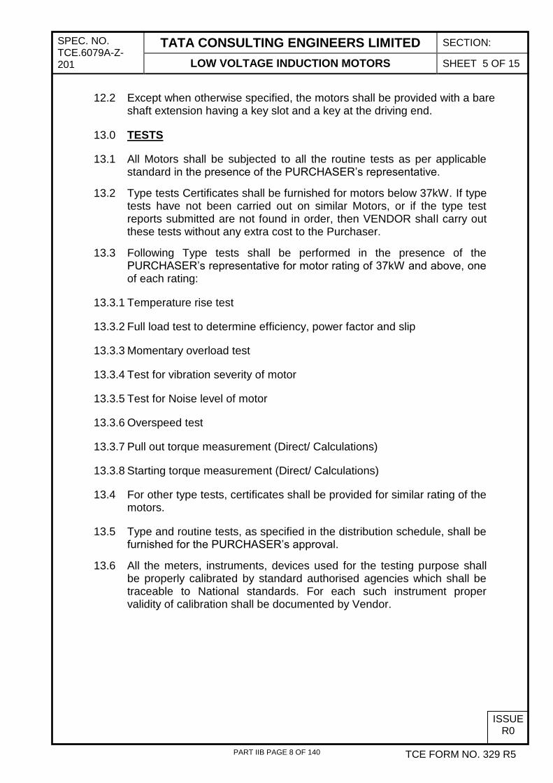
12.2 Except when otherwise specified, the motors shall be provided with a bare shaft extension having a key slot and a key at the driving end.
13.0 TESTS
13.1 All Motors shall be subjected to all the routine tests as per applicable standard in the presence of the PURCHASER’s representative.
13.2 Type tests Certificates shall be furnished for motors below 37kW. If type tests have not been carried out on similar Motors, or if the type test reports submitted are not found in order, then VENDOR shall carry out these tests without any extra cost to the Purchaser.
13.3 Following Type tests shall be performed in the presence of the PURCHASER’s representative for motor rating of 37kW and above, one of each rating:
13.3.1 Temperature rise test
13.3.2 Full load test to determine efficiency, power factor and slip
13.3.3 Momentary overload test
13.3.4 Test for vibration severity of motor
13.3.5 Test for Noise level of motor
13.3.6 Overspeed test
13.3.7 Pull out torque measurement (Direct/ Calculations)
13.3.8 Starting torque measurement (Direct/ Calculations)
13.4 For other type tests, certificates shall be provided for similar rating of the motors.
13.5 Type and routine tests, as specified in the distribution schedule, shall be furnished for the PURCHASER’s approval.
13.6 All the meters, instruments, devices used for the testing purpose shall be properly calibrated by standard authorised agencies which shall be traceable to National standards. For each such instrument proper validity of calibration shall be documented by Vendor.
PART IIB PAGE 8 OF 140
SPECIFICATION NO. TCE. 6079A-Z-201
TATA CONSULTING ENGINEERS LIMITED SECTION:
LOW VOLTAGE INDUCTION MOTORS DATA SHEET A1 SHEET 6 OF 15
SL. NO. ITEM UNIT
REV. NO. 0 JOB NO.
TCE.
6079A
CLIENT: BHARAT PETROLEUM CORPORATION LIMITED, MUMBAI
PPD. BY MKS
CHD. BY AVD PROJECT: OFFSITES AND UTILITIES FOR CCR
DATE 30.06.10 TCE FORM NO. 330 R3
ISSUE R0
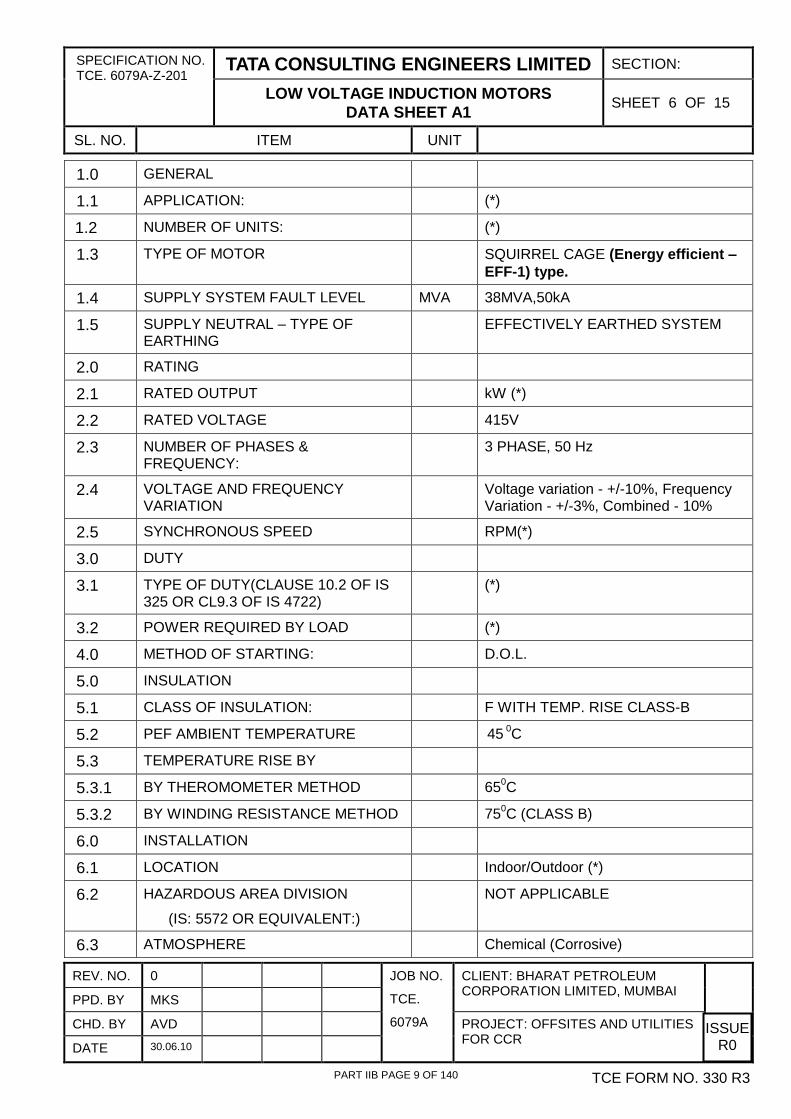
1.0 GENERAL
1.1 APPLICATION: (*)
1.2 NUMBER OF UNITS: (*)
1.3 TYPE OF MOTOR SQUIRREL CAGE (Energy efficient – EFF-1) type.
1.4 SUPPLY SYSTEM FAULT LEVEL MVA 38MVA,50kA
1.5 SUPPLY NEUTRAL – TYPE OF EARTHING
EFFECTIVELY EARTHED SYSTEM
2.0 RATING
2.1 RATED OUTPUT kW (*)
2.2 RATED VOLTAGE 415V
2.3 NUMBER OF PHASES & FREQUENCY:
3 PHASE, 50 Hz
2.4 VOLTAGE AND FREQUENCY VARIATION
Voltage variation - +/-10%, Frequency Variation - +/-3%, Combined - 10%
2.5 SYNCHRONOUS SPEED RPM(*)
3.0 DUTY
3.1 TYPE OF DUTY(CLAUSE 10.2 OF IS 325 OR CL9.3 OF IS 4722)
(*)
3.2 POWER REQUIRED BY LOAD (*)
4.0 METHOD OF STARTING: D.O.L.
5.0 INSULATION
5.1 CLASS OF INSULATION: F WITH TEMP. RISE CLASS-B
5.2 PEF AMBIENT TEMPERATURE 45 0C
5.3 TEMPERATURE RISE BY
5.3.1 BY THEROMOMETER METHOD 650C
5.3.2 BY WINDING RESISTANCE METHOD 750C (CLASS B)
6.0 INSTALLATION
6.1 LOCATION Indoor/Outdoor (*)
6.2 HAZARDOUS AREA DIVISION
(IS: 5572 OR EQUIVALENT:)
NOT APPLICABLE
6.3 ATMOSPHERE Chemical (Corrosive)
PART IIB PAGE 9 OF 140

SPECIFICATION NO. TCE. 6079A-Z-201
TATA CONSULTING ENGINEERS LIMITED SECTION:
LOW VOLTAGE INDUCTION MOTORS DATA SHEET A1 SHEET 7 OF 15
SL. NO. ITEM UNIT
REV. NO. 0 JOB NO.
TCE.
6079A
CLIENT: BHARAT PETROLEUM CORPORATION LIMITED, MUMBAI
PPD. BY MKS
CHD. BY AVD PROJECT: OFFSITES AND UTILITIES FOR CCR
DATE 30.06.10 TCE FORM NO. 330 R3
ISSUE R0
7.0 ENCLOSURE
7.1 TYPE OF COOLING (IS 6362) TEFC
7.2 DESIGNATION OF DEGREE OF PROTECTION (IS 4691)
IP 55
8.0 MAIN TERMINAL BOX
8.1 LOCATION AS SEEN FROM NON- DRIVE END
RIGHT/LEFT/TOP (*)
8.2 RATING
1, SHORT TIME
CURRENT:
DURATION:
2. DYNAMIC
(*)
50kA (RMS)
0.25 SECS
kA (PEAK)
8.3 EXTERNAL CABLE DETAILS (#)
8.3.1 TYPE
8.3.2 SIZE AND NUMBER OF CORES
8.4 EARTHING CONDUCTORS
8.4.1 MATERIAL Copper Insulated cable
8.4.2 SIZE (#)
9.0 MISCELLANEOUS REQUIREMENT
9.1 SHAFT ORIENTATION: HORIZONTAL/VERTICAL/HOLLOW VERTICAL (*)
9.2 MOUNTING SYMBOL
(IS :2253 OR EQUIVALENT)
(*)
9.3 ROTATION AS SEEN FROM NON-DRIVEN END
CLOCKWISE/ANTICLOCKWISE(*)
9.4 TYPE OF BEARING DRIVE END/NON DRIVE END(*)
9.5 WHETHER BED PLATE REQUIRED YES/NO (#)
10.0 COLOUR SHADES OF PLANT IF SPECIAL
Light Gray – Shade 631 of IS-5. Special varnishing and painting treatment to be given as the atmosphere is highly corrosive.
11.0 CTS FOR DIFFERENTIAL PROTECTION REQUIRED
NO
PART IIB PAGE 10 OF 140

SPECIFICATION NO. TCE. 6079A-Z-201
TATA CONSULTING ENGINEERS LIMITED SECTION:
LOW VOLTAGE INDUCTION MOTORS DATA SHEET A1 SHEET 8 OF 15
SL. NO. ITEM UNIT
REV. NO. 0 JOB NO.
TCE.
6079A
CLIENT: BHARAT PETROLEUM CORPORATION LIMITED, MUMBAI
PPD. BY MKS
CHD. BY AVD PROJECT: OFFSITES AND UTILITIES FOR CCR
DATE 30.06.10 TCE FORM NO. 330 R3
ISSUE R0
11.1 $ CT PARTICULARS
A) 3 CTS, ONE IN THE NEUTRAL LEAD OF EACH PHASE
B) RATIO
C) CLASS P. S.
D) KNEE POINT VOLTAGE
E) MAX. R. C. T. SECONDARY WINDING,
F) MAX. EXCITING CURRENT AT 1/2 KPV
G) CLASS OF INSULATION
NOT APPLICABLE
11.2 VIBRATION PADS REQUIRED (#)
12.0 TEMPERATURE DETECTORS / INDICATORS
12.1.1 EMBEDDED TEMPERATURE DETECTORS FOR WINDING REQUIRED
NO
12.1.2 EMBEDDED TEMPERATURE DETECTORS FOR BEARINGS REQUIRED
NO
12.1.3 BEARING THERMOMETERS FOR DRIVING END & NON DRIVING ENDS REQUIRED
NO
12.1.4 THERMISTERS FOR MOTORS REQUIRED
YES FOR MOTORS ABOVE 110 kW AND VFD DRIVEN MOTORS
13.0 SPACE HEATERS FOR MOTORS REQUIRED
YES FOR MOTORS ABOVE 30 KW
NOTES:
1. DETAILS MARKED THUS (*) WILL BE DECIDED AND INTIMATED BY THE BIDDER BASED ON DRIVEN EQUIPMENT CHARACTERISTICS
2. DATA MARKED THUS (#) WILL BE INTIMATED TO VENDOR AFTER PLACEMENT OF
ORDER.
PART IIB PAGE 11 OF 140

SPECIFICATION NO. TCE. 6079A-Z-201
TATA CONSULTING ENGINEERS LIMITED SECTION:
LOW VOLTAGE INDUCTION MOTORS DATA SHEET A2 SHEET 9 OF 15
SL. NO. ITEM
REV. NO. 0 JOB NO.
TCE.
6079A
CLIENT: BHARAT PETROLEUM CORPORATION LIMITED, MUMBAI
PPD. BY MKS
CHD. BY AVD PROJECT: OFFSITES AND UTILITIES FOR CCR
DATE 30.06.10 TCE FORM NO. 330 R3
ISSUE R0
1. INDUCTION MOTORS – THREE PHASE IS-325 BS EN- 60034-1
IEC-60034-1
2. ROTATING ELECTRICAL MACHINES IS-4722
3. SINGLE PHASE INDUCTION MOTOR IS-996
4. CODE OF PRACTICE FOR CLIMATE PROOFING BS EN- 60034-5
IEC-60034-5
5. DESIGNATIONS FOR TYPES OF CONSTRUCTION AND MOUNTING ARRANGEMENTS OF ROTATING ELECTRICAL MACHINES
IS-2253 BS EN-60034-7
IEC-60034-7
6. TERMINAL MARKING FOR ROTATING ELECTRICAL MACHINERY
IS-4728 BS EN- 60034-8
IEC-60034-8
7. DESIGNATION OF METHODS OF COOLING FOR ROTATING ELECTRICAL MACHINES
IS-6362 BS EN- 60034-6
IEC-60034-6
8. DEGREE OF PROTECTION PROVIDED BY ENCLOSURE FOR ROTATING ELECTRICAL MACHINERY
IS-4691 BS EN-60034-3
IEC-60034-3
9. GUIDE FOR TESTING THREE PHASE INDUCTION MOTORS
IS-4029 BS EN- 60079-1
IEC-60034-1
10. MEASUREMENT AND EVALUATION OF VIBRATION OF ROTATING ELECTRICAL MACHINES
IS-12075 BS EN-60034-14
IEC-60034-14
11. CLASSIFICATION OF HAZARDOUS AREAS FOR ELECTRICAL INSTALLATION
IS-5572 BS EN-60079-10
IEC-60079-10
12. DESIGNATION OF SLIDE RAILS FOR ELECTRIC MOTOR
IS-2968 BS EN- 60034-1
13. PERMISSIBLE LIMITS FOR NOISE LEVEL FOR ROTATING ELECTRICAL MACHINES
IS-12065 BS EN-60034-9
IEC-60034-9
14. GUIDE FOR TESTING INSULATION RESISTANCE OF ROTATING MACHINE
IS-7816
15. TEST PROCEDURES FOR MEASUREMENT OF LOSS TANGENT ANGLE OF COIL AND BAR FOR MACHINE WINDING - GUIDE
IS-13508
16. IMPULSE VOLTAGE WITHSTAND LEVEL IEC-60034-15
17. INDUCTION MOTORS - ENERGY EFFICIENT IS-12615
PART IIB PAGE 12 OF 140

SPECIFICATION NO. TCE. 6079A-Z-201
TATA CONSULTING ENGINEERS LIMITED SECTION:
LOW VOLTAGE INDUCTION MOTORS DATA SHEET A2 SHEET 10 OF 15
SL. NO. ITEM
REV. NO. 0 JOB NO.
TCE.
6079A
CLIENT: BHARAT PETROLEUM CORPORATION LIMITED, MUMBAI
PPD. BY MKS
CHD. BY AVD PROJECT: OFFSITES AND UTILITIES FOR CCR
DATE 30.06.10 TCE FORM NO. 330 R3
ISSUE R0
18. TEMPERATURE RISE MEASUREMENT OF ROTATING ELECTRICAL MACHINES
IS-12802
19. TYPE OF DUTY AND CLASSES OF RATING ASSIGNED TO ROTATING ELECTRICAL MACHINES
IS-12824
20. ADJUSTABLE SPEED ELECTRICAL POWER DRIVE SYSTEM- EMC REQUIREMENTS AND SPECIFIC TEST METHODS.
BS-EN-61800
IEC-61800
21. DIMENSIONS AND OUTPUT SERIES FOR ROTATING ELECTRICAL MACHINES.
IS-1231 BS-4999-141
IEC- 60072-1
22. ELECTRICAL APPARATUS FOR EXPLOSIVE GAS ATMOSPHERE – CLASSIFICATION OF HAZARDOUS AREA.
IS-5571
BS-EN-60079
IEC-60079-10
23. TEMPERATURE RISE MEASUREMENT OF ROTATING ELECTRICAL MACHINES
IS-12802
24. TYPE OF DUTY AND CLASSES OF RATING ASSIGNED TO ROTATING ELECTRICAL MACHINES
IS-12824
NOTE : EQUIPMENT, ASSOCIATED ACCESSORIES, COMPONENTS/PARTS, RAW MATERIAL AND TESTS SHALL IN GENERAL CONFORM TO IS.
PART IIB PAGE 13 OF 140
SPECIFICATION NO. TCE. 6079A-Z-201
TATA CONSULTING ENGINEERS LIMITED SECTION:
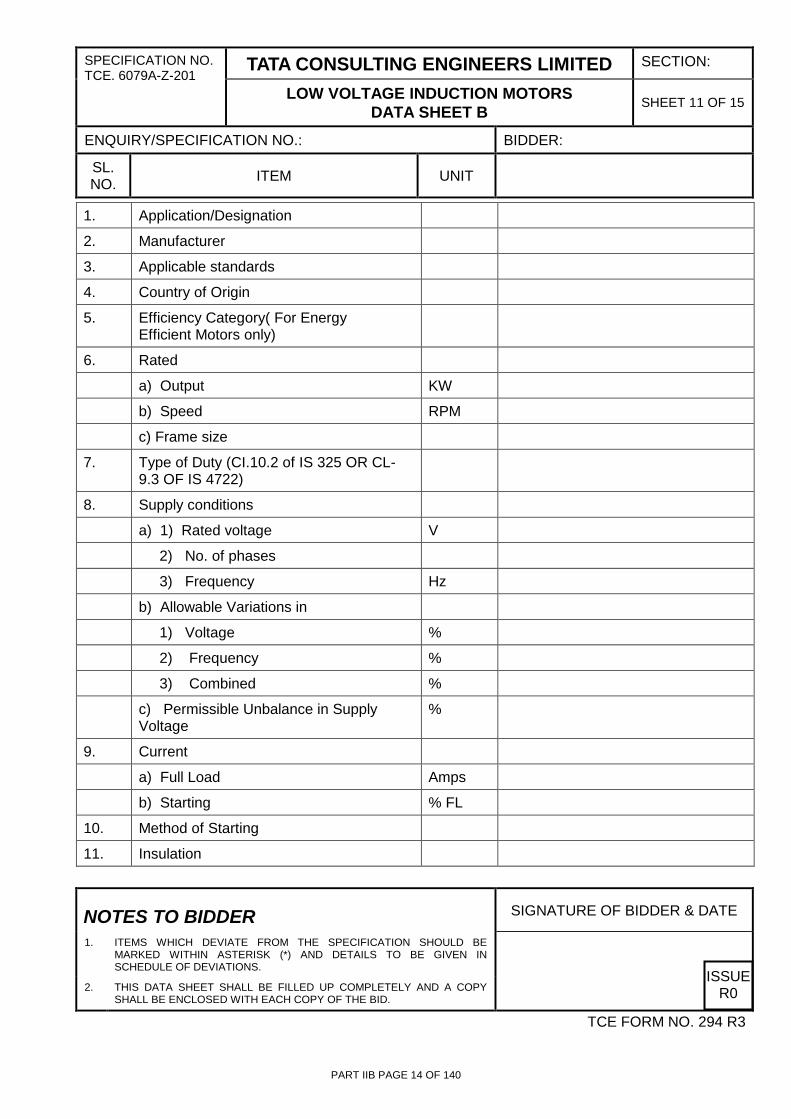
LOW VOLTAGE INDUCTION MOTORS DATA SHEET B SHEET 11 OF 15
ENQUIRY/SPECIFICATION NO.: BIDDER:
SL. NO. ITEM UNIT
NOTES TO BIDDER SIGNATURE OF BIDDER & DATE
1. ITEMS WHICH DEVIATE FROM THE SPECIFICATION SHOULD BE MARKED WITHIN ASTERISK (*) AND DETAILS TO BE GIVEN IN SCHEDULE OF DEVIATIONS.
2. THIS DATA SHEET SHALL BE FILLED UP COMPLETELY AND A COPY SHALL BE ENCLOSED WITH EACH COPY OF THE BID.
ISSUE R0
TCE FORM NO. 294 R3
1. 0 Application/Designation
2. 0 Manufacturer
3. Applicable standards
4. Country of Origin
5. Efficiency Category( For Energy Efficient Motors only)
6. 3 Rated
a) Output KW
b) Speed RPM
c) Frame size
7. Type of Duty (CI.10.2 of IS 325 OR CL-9.3 OF IS 4722)
8. Supply conditions
a) 1) Rated voltage V
2) No. of phases
3) Frequency Hz
b) Allowable Variations in
1) Voltage %
2) Frequency %
3) Combined %
c) Permissible Unbalance in Supply Voltage
%
9. Current
a) Full Load Amps
b) Starting % FL
10. Method of Starting
11. Insulation
PART IIB PAGE 14 OF 140

SPECIFICATION NO. TCE. 6079A-Z-201
TATA CONSULTING ENGINEERS LIMITED SECTION:
LOW VOLTAGE INDUCTION MOTORS DATA SHEET B SHEET 12 OF 15
ENQUIRY/SPECIFICATION NO.: BIDDER:
SL. NO. ITEM UNIT
NOTES TO BIDDER SIGNATURE OF BIDDER & DATE
1. ITEMS WHICH DEVIATE FROM THE SPECIFICATION SHOULD BE MARKED WITHIN ASTERISK (*) AND DETAILS TO BE GIVEN IN SCHEDULE OF DEVIATIONS.
2. THIS DATA SHEET SHALL BE FILLED UP COMPLETELY AND A COPY SHALL BE ENCLOSED WITH EACH COPY OF THE BID.
ISSUE R0
TCE FORM NO. 294 R3
11.1 Class of Insulation
11.2 Whether Tropicalised Yes/No
12. a) Reference ambient Temperature
b) Temp. rise by res. Method
Stator 0 C
Rotor 0 C
c) Temp. rise of bearing 0 C
13. Degree of Protection(IS 4691 or equivalent)
14. Suitable for Outdoor Operation Yes/No
15. Normal winding connection Star/Delta
16. Space Heater rating Watt
17. (i) Type & No. of Terminals brought Out
(ii) Fault withstand capacity at rated voltage & duration
iii) Maximum size of Aluminium armoured cable that can be Terminated
cores X Sq mm
18. Dimensional Dwg. Enclosed
19. Torque
19.1 Full Load Kg-m
19.2 Starting torque %FLT
19.3 Pull out Torque %FLT
19.4 Pull up Torque %FLT
PART IIB PAGE 15 OF 140

SPEC. NO. TCE. 6079A-Z-201
TATA CONSULTING ENGINEERS LIMITED SECTION:
LOW VOLTAGE INDUCTION MOTORS DATA SHEET-C SHEET 13 OF 15
ISSUE R0
TCE FORM NO. 329 R5
INFORMATION TO BE SUBMITTED BY THE VENDOR
AFTER AWARD OF CONTRACT
1.0 Technical particulars as per data sheet B of tender specification. (Based on motor manufacturer)
2.0 Type and frame size :
3.0 Starting time (Secs)
3.1 With 100% voltage at terminals
3.2 With minimum voltage at terminals (at ____ % Rated voltage)
3.3 With 110% voltage at terminals
4.0 Safe stall time at 100/110% rated voltage under hot/cold condition.
5.0 Type and size of cable for which gland is provided in the terminal box :
6.0 Type of bearings and expected life.
7.0 Total weight of motor (kg)
7.1 Weight of Stator (kg)
7.2 Weight of Rotor (kg)
8.0 Motor GD2 :
9.0 Efficiency (%)
9.1 Full Load Efficiency
9.2 75% Load Efficiency
9.3 50% Load Efficiency
9.4 25% Load Efficiency
10.0 Power Factor
10.1 Full Load Power Factor
10.2 75% Load Power Factor
PART IIB PAGE 16 OF 140

SPEC. NO. TCE. 6079A-Z-201
TATA CONSULTING ENGINEERS LIMITED SECTION:
LOW VOLTAGE INDUCTION MOTORS DATA SHEET-C SHEET 14 OF 15
ISSUE R0
TCE FORM NO. 329 R5
10.3 50% Load Power Factor
10.4 25% Load Power Factor
11.0 Torque (% FLT)
11.1 Starting
11.2 Maximum (Pullout torque)
11.3 Pull up torque
12.0 Type of Enclosure
13.0 Cooling designation
14.0 Space heaters
14.1 Rated voltage/number
14.2 Rating total
14.3 Separate terminal box provided
15.0 Motor reactances (Pu)
15.1 Subtransient reactance
15.2 Transient reactance
15.3 Steady state reactance
16.0 Guaranteed losses (kW)
16.1 Iron loss
16.2 Copper loss
16.3 Friction, Windage & Stray losses.
17.0 Motor outline dimension drawing (Number of copies as per distribution schedule)
18.0 Type test certificates (Number of copies as per distribution schedule)
19.0 Speed torque curve at rated & minimum starting voltage.
PART IIB PAGE 17 OF 140

SPEC. NO. TCE. 6079A-Z-201
TATA CONSULTING ENGINEERS LIMITED SECTION:
LOW VOLTAGE INDUCTION MOTORS DATA SHEET-C SHEET 15 OF 15
ISSUE R0
TCE FORM NO. 329 R5
20.0 Current - speed curve.
21.0 Current - time curve.
22.0 Efficiency, power factor, slip, current against output curve.
23.0 Thermal withstand characteristic for motors of 100 kW & above - Hot & Cold.
24.0 Negative sequence current Vs time curve for motor of 100 kW & above.
25.0 Rotor voltage/Rotor current (for wound motors).
PART IIB PAGE 18 OF 140

SPEC. NO. TCE.6079A-Z-203
TATA CONSULTING ENGINEERS LIMITED SECTION:
HIGH VOLTAGE INDUCTION MOTORS SHEET 1 OF 21
ISSUE R0
TCE FORM NO. 329 R5
1.0 SCOPE
1.1 The specification covers the design, material, constructional features, manufacture, inspection and testing at the VENDOR'S/his SUB-VENDOR'S works, delivery to site and performance testing of High Voltage induction motors rated above 1000V.
2.0 CODES AND STANDARDS
2.1 The design, material, construction, manufacture, inspection, testing and performance of induction motors shall comply with all currently applicable statutes, regulations and safety codes in the locality where the equipment will be installed. The equipment shall also conform to the applicable standards specified in data sheet A1 latest revision as on the date of offer Nothing in this specification shall be construed to relieve the VENDOR of this responsibility. In case of conflict between the standards and this specification, this specification shall govern.
3.0 DRIVEN EQUIPMENT
3.1 When this specification forms part of the driven equipment specification, information not given in the Data Sheet-A will be governed by the driven equipment specification.
3.2 Motors shall be capable of satisfactory operation for the application and duty as specified in the motor Data Sheet-A and as specified for the driven equipment.
4.0 PERFORMANCE AND CHARACTERISTICS
4.1 Motors shall be capable of giving rated output without reduction in the expected life span when operated continuously under either of the following supply conditions as specified in Data Sheet-A1.
Supply Condition
I II
a) variation of supply voltage from rated voltage
+/- 6% +/-10%
b) Variation in supply frequency from rated frequency
+/- 3% +/- 5%
c) Combined voltage and frequency variation +/- 6% +/-10%
4.2 Motors shall be suitable for the method of starting specified in the Data Sheet-A.
PART IIB PAGE 19 OF 140

SPEC. NO. TCE.6079A-Z-203
TATA CONSULTING ENGINEERS LIMITED SECTION:
HIGH VOLTAGE INDUCTION MOTORS SHEET 2 OF 21
ISSUE R0
TCE FORM NO. 329 R5
4.3 Motors shall be capable of starting and accelerating the load with the applicable method of starting, without exceeding acceptable winding temperatures, when the supply voltage is 80% of the rated voltage.
4.4 Motors shall be capable of satisfactory operation at full load at a supply voltage of 80% of the rated voltage for 5 minutes, commencing from hot condition.
4.5 Motors shall withstand the voltage and torque stresses developed due to the vector difference between the motor residual voltage and the incoming supply voltage equal to 150% of the rated voltage, during fast change over of buses. The duration of this condition is envisaged for a period of one second.
4.6 The locked rotor current of the motors shall not exceed the following values which are inclusive of 20% tolerance.
4.6.1 600% of full load current for motors upto and including 1500 kW.
4.6.2 450% of full load current for motors above 1500 kW.
4.7 Motors shall be capable of developing the rated full load torque even if the supply voltage drops to 70% of the rated voltaget The pull out torque of the motor shall be atleast 205% of full load torque.
4.8 Motors when started with the driven equipment coupled shall be capable of withstanding at least two successive starts from cold conditions & one start from hot condition without injurious heating of windings. The motors shall also be suitable for three equally spread starts per hour under the above referred supply conditions.
4.9 The locked rotor withstand time under hot conditions at 110% rated voltage shall be more than the starting time at minimum permissible voltage (clause 2.1 above) by atleast three seconds or 15% of the accelerating time whichever is greater. Provision of speed switch shall be avoided to the extent possible. In case the speed switch is required, it shall be indicated out by the bidder in his offer.
4.10 When a speed switch is mounted on the motor shaft , the same shall remain closed for speeds lower than 20% and open for speeds above 20% of the rated speed.The speed switch shall be capable of withstanding 120% over speed in either direction of rotation. If the speed switch requires any auxiliary voltage, it shall be suitable for the auxiliary voltage specified in Section-B - Project Information of the specification.
PART IIB PAGE 20 OF 140

SPEC. NO. TCE.6079A-Z-203
TATA CONSULTING ENGINEERS LIMITED SECTION:
HIGH VOLTAGE INDUCTION MOTORS SHEET 3 OF 21
ISSUE R0
TCE FORM NO. 329 R5
5.0 INSULATION
5.1 Motors shall be given power house treatment. Additional treatments to withstand heavily salt polluted or similar atmospheric conditions shall be given based on the location indicated in Data Sheet-A
5.2 The insulation system shall withstand steep front impulse voltage of value given as per Table-1 of IEC-34-15 having front time of 0.2 microsecond.
6.0 TEMPERATURE RISE
6.1 The temperature rises shall not exceed the values given in IS 12802. Under extremes of supply condition (clause 4.1 above), the temperature rise shall not exceed the value indicated in IS by 10oC.
6.2 For motors specified for outdoor installation heating due to direct exposure to solar radiation shall be considered.
6.3 Atleast six resistance type temperature detectors for the stator winding each having D.C. resistance of 100 ohms at 0oC, embedded in the stator winding at locations where highest temperatures may be expected, shall be provided. The material of the ETD's shall be platinum. One ETD shall be provided for each of the motor bearing & shall be wired upto the terminal box. The temperature detectors shall be of 3 wire , duplex type.
7.0 CONSTRUCTIONAL FEATURES
7.1 All insulated windings shall be of Copper.
7.2 All Motors shall be provided with eyebolts, lugs or other means to facilitate safe lifting.
7.3 Motors shall be provided with drain plugs, so located to drain water, resulting from condensation or due to other causes ,from all pockets in the motor casing.
7.4 Vibration pads shall be provided when called for in the specification.
8.0 BEARINGS
8.1 Unless otherwise specified in data sheet-A, motor bearings shall not be subjected to any external thrust load.
8.2 Unless otherwise specified, motor bearings shall have an estimated life of atleast 40,000 hrs.
8.3 The bearings shall permit running of the motor in either direction of rotation.
PART IIB PAGE 21 OF 140

SPEC. NO. TCE.6079A-Z-203
TATA CONSULTING ENGINEERS LIMITED SECTION:
HIGH VOLTAGE INDUCTION MOTORS SHEET 4 OF 21
ISSUE R0
TCE FORM NO. 329 R5
8.4 When forced oil lubrication or water cooling is required, prior approval from the purchaser shall be obtained.
8.5 When forced oil lubrication or water cooling is required, the machine shall be suitable for starting & continuous operation for atleast 10 minutes, without the availability of lubrication or cooling system.
8.6 If the bearings are oil lubricated, a drain plug shall be provided for draining residual oil & an oil level sight gauge shall be provided to show the precise oil level required for stand still and running conditions.
8.7 It shall be possible to lubricate the bearings without dismantling any part of the motor.
8.8 Each bearing shall be provided with a dial type thermometer. Each thermometer shall consist of 2 potential free contacts. They shall be designed to close independently at two different temperatures - one for 'Alarm' and another for 'Trip'.
8.9 The contact rating of the potential free contacts shall be 1A at 240V AC & 0.1A at 220V DC. Any auxiliary supply, if required shall be indicated by the bidder.
8.10 The thermometers shall be located at a convenient height for easy reading and handling.
8.11 Flow switches shall be provided for monitoring cooling water flow if CACW motors are specified.
8.12 One bearing shall be insulated to prevent shaft currents.
9.0 TERMINAL BOX
9.1 Separate terminal boxes shall be provided for each of the following :
9.1.1 Stator Leads
9.1.2 Rotor leads (wound motors)
9.1.3 Space Heaters
9.1.4 Temperature Detectors
9.2 The three phases shall be segregated by barriers of metal or fibre glass.
9.3 The cable box design shall be suitable for any type of cable termination kits available.
PART IIB PAGE 22 OF 140

SPEC. NO. TCE.6079A-Z-203
TATA CONSULTING ENGINEERS LIMITED SECTION:
HIGH VOLTAGE INDUCTION MOTORS SHEET 5 OF 21
ISSUE R0
TCE FORM NO. 329 R5
9.4 Terminal boxes shall have a degree of protection of atleast IP 55 for out door applicable
9.5 Unless otherwise approved, the terminal box shall be capable of being turned through 360o in steps of 90o.
9.6 Terminals shall be of stud type & the terminal box shall be complete with necessary lugs, nuts, washers.
9.7 When single core cables are to be used the gland plates shall be of non magnetic material.
9.8 Sizes of terminal boxes and lugs shall suit the cable sizes mentioned in Data Sheet- A.
10.0 PAINT AND FINISH
10.1 All motor parts exposed directly to atmosphere shall be finished and painted to produce a neat and durable surface which would prevent rusting and corrosion. The equipment shall be thoroughly degreased, all rust, sharp edges and scale removed and treated with one coat of primer and finished with two coats of grey enamel paint.
11.0 HEATING DURING IDLE PERIODS
11.1 Motors rated shall have space heaters suitable for 240V, single phase, 50 Hz, AC supply. Space heaters shall have adequate capacity to maintain motor internal temperature above dew point to prevent moisture condensation during idle period. The space heaters shall be placed in easily accessible positions in the lowest part of the motor frame.
12.0 ACCESSORIES
12.1 Two independent earthing points shall be provided on opposite sides of the motor, for bolted connection of the PURCHASER'S earthing conductors as specified in data sheet-A. The earthing pads shall be of non-corrodible metal welded or brazed. These earthing points shall be in addition to earthing stud provided in the terminal box.
12.2 Except when otherwise specified, the motors shall be provided with a bare shaft extension having a key slot and a key at the driving end.
12.3 The following details, in addition to those specified in applicable standards shall be included on the rating plate.
12.3.1 Temperature rise of windings in degree centigrade at rated load, rated voltage, frequency and ambient conditions and the method of measuring temperature rise. (Thermometer/ Winding resistance).
PART IIB PAGE 23 OF 140

SPEC. NO. TCE.6079A-Z-203
TATA CONSULTING ENGINEERS LIMITED SECTION:
HIGH VOLTAGE INDUCTION MOTORS SHEET 6 OF 21
ISSUE R0
TCE FORM NO. 329 R5
12.3.2 Type of bearings, recommended lubricant, lubricating interval & re-lubricating quantity.
13.0 TESTS
13.1 All Motors shall be subjected to all the routine tests as per applicable standard in the presence of the PURCHASER’s representative.
13.2 Following Type tests shall be performed in the presence of the PURCHASER’s representative for one of each rating:
13.2.1 Temperature rise test
13.2.2 Full load test to determine efficiency, power factor and slip
13.2.3 Momentary overload test
13.2.4 Test for vibration severity of motor
13.2.5 Test for Noise level of motor
13.2.6 Overspeed test
13.2.7 Pull out torque measurement (Direct/ Calculations)
13.2.8 Starting torque measurement (Direct/ Calculations)
13.3 For other type tests, certificates shall be provided for similar rating of the motors.
13.4 Type and routine tests, as specified in the distribution schedule, shall be furnished for the PURCHASER’s approval.
13.5 All the meters, instruments, devices used for the testing purpose shall be properly calibrated by standard authorised agencies which shall be traceable to National standards. For each such instrument proper validity of calibration shall be documented by Vendor.
13.6 If specified in data sheet-A, for motors rated 3.3 kV and above, the induced shaft voltage shall be measured at the manufacturer's works during shop testing. The maximum value of induced voltage in the motor shaft shall not exceed 250mV.
13.7 The polarisation index test shall be carried out on all motors rated at 3.3 kV and above. The minimum value of the polarisation index shall be 2 when determined as per IS-7816.
13.8 Coils of HV motors shall be tested as per IEC-60034-15. Dielectric tests to establish the insulation withstand level of Motors as indicated in clause
PART IIB PAGE 24 OF 140

SPEC. NO. TCE.6079A-Z-203
TATA CONSULTING ENGINEERS LIMITED SECTION:
HIGH VOLTAGE INDUCTION MOTORS SHEET 7 OF 21
ISSUE R0
TCE FORM NO. 329 R5
5.2 above shall be performed on a sample coil (identical to that to be used in the motor quoted for) for each type of HT Motor.
13.9 Loss tangent measurement of coils for motors rated 6.6 kV & above shall be done as per IS-13508.
PART IIB PAGE 25 OF 140

SPECIFICATION NO. TCE. 6079A-Z-203
TATA CONSULTING ENGINEERS LIMITED SECTION:
HIGH VOLTAGE INDUCTION MOTORS DATA SHEET A1 SHEET 8 OF 21
SL. NO. ITEM UNIT
REV. NO. 0 JOB NO.
TCE.
6079A
CLIENT: BHARAT PETROLEUM CORPORATION LIMITED, MUMBAI
PPD. BY MKS
CHD. BY AVD PROJECT: OFFSITES AND UTILITIES FOR CCR
DATE 30.06.10 TCE FORM NO. 330 R3
ISSUE R0
1.0 GENERAL
1.1 APPLICATION: (*)
1.2 NUMBERS REQUIRED (*)
1.3 TYPE OF MOTOR SQUIRREL CAGE
1.4 SUPPLY SYSTEM FAULT LEVEL MVA 457MVA,40KA
1.5 SUPPLY NEUTRAL – TYPE OF EARTHING
RESISTANCE EARTHED SYSTEM (EARTH FAULT CURRENT – 400A)
2.0 RATING
2.1 RATED OUTPUT kW (*)
2.2 RATED VOLTAGE 6.6 kV
2.3 NUMBER OF PHASES & FREQUENCY 3 PHASE, 50 Hz
2.4 VOLTAGE AND FREQUENCY VARIATION
Voltage variation - +/-10%, Frequency Variation - +/-3%, Combined - 10%
2.5 SYNCHRONOUS SPEED RPM (*)
3.0 DUTY
3.1 TYPE OF DUTY(CLAUSE 10.2 OF IS 325 OR CL9.3 OF IS 4722)
(*)
3.2 POWER REQUIRED BY LOAD (*)
4.0 METHOD OF STARTING D.O.L.
5.0 INSULATION
5.1 CLASS OF INSULATION: F WITH TEMP. RISE CLASS-B
5.2 PEF AMBIENT TEMPERATURE 45 0C
5.3 TEMPERATURE RISE BY WDG RESISTANCE METHOD
750C (CLASS B)
6.0 INSTALLATION
6.1 LOCATION Outdoor
6.2 HAZARDOUS AREA DIVISION
(IS: 5572 OR EQUIVALENT:)
NOT APPLICABLE
6.3 ATMOSPHERE Chemical (Corrosive)
7.0 ENCLOSURE
7.1 TYPE OF COOLING (IS 6362) TEFC/CACA
PART IIB PAGE 26 OF 140

SPECIFICATION NO. TCE. 6079A-Z-203
TATA CONSULTING ENGINEERS LIMITED SECTION:
HIGH VOLTAGE INDUCTION MOTORS DATA SHEET A1 SHEET 9 OF 21
SL. NO. ITEM UNIT
REV. NO. 0 JOB NO.
TCE.
6079A
CLIENT: BHARAT PETROLEUM CORPORATION LIMITED, MUMBAI
PPD. BY MKS
CHD. BY AVD PROJECT: OFFSITES AND UTILITIES FOR CCR
DATE 30.06.10 TCE FORM NO. 330 R3
ISSUE R0
7.2 DESIGNATION OF DEGREE OF PROTECTION (IS 4691)
IP 55
8.0 MAIN TERMINAL BOX
8.1 LOCATION AS SEEN FROM NON- DRIVE END
RIGHT/LEFT/TOP (*)
8.2 RATING
1, SHORT TIME
CURRENT:
DURATION:
2. DYNAMIC
(*)
40kA (RMS)
0.25 SECS
kA (PEAK)
8.3 EXTERNAL CABLE DETAILS (#)
8.3.1 TYPE 6.6kV (UE), XLPE ARMOURRED
8.3.2 SIZE AND NUMBER OF CORES 3Cx185 ALUMINUM
8.4 EARTHING CONDUCTORS
8.4.1 MATERIAL Copper Insulated cable
8.4.2 SIZE (#)
9.0 MISCELLANEOUS REQUIREMENT
9.1 SHAFT ORIENTATION: HORIZONTAL/VERTICAL/HOLLOW VERTICAL (*)
9.2 MOUNTING SYMBOL
(IS :2253 OR EQUIVALENT)
(*)
9.3 ROTATION AS SEEN FROM NON-DRIVEN END
CLOCKWISE/ANTICLOCKWISE(*)
9.4 TYPE OF BEARING DRIVE END/NON DRIVE END(*)
9.5 WHETHER BED PLATE REQUIRED YES/NO (#)
9.6 MOTOR SHALL MATCH THE FOLLOWING TORQUE REQUIREMENTS OF THE DRIVEN EQUIPMENT:
(*)
a) STARTING TORUE b) FULL LOAD (RATED) TORQUE c) PULL OUT TORQUE d) PULL UP TORQUE
(*)
9.7 COUPLING BY MOTOR SUPPLIER NO
PART IIB PAGE 27 OF 140

SPECIFICATION NO. TCE. 6079A-Z-203
TATA CONSULTING ENGINEERS LIMITED SECTION:
HIGH VOLTAGE INDUCTION MOTORS DATA SHEET A1 SHEET 10 OF 21
SL. NO. ITEM UNIT
REV. NO. 0 JOB NO.
TCE.
6079A
CLIENT: BHARAT PETROLEUM CORPORATION LIMITED, MUMBAI
PPD. BY MKS
CHD. BY AVD PROJECT: OFFSITES AND UTILITIES FOR CCR
DATE 30.06.10 TCE FORM NO. 330 R3
ISSUE R0
9.8 IF YES, TYPE OF COUPLING
9.9 GD2 of LOAD
10.0 COLOUR SHADES OF PAINT Light Gray – Shade 631 of IS-5 Special varnishing and painting treatment to be given as the atmosphere is highly corrosive.
11.0 WHETHER CTs FOR DIFFERENTIAL PROTECTION REQUIRED FOR MOTORS >1000 kW
12.0 CTS FOR DIFFERENTIAL PROTECTION REQUIRED
YES
12.1 CT PARTICULARS A) 3 CTS, ONE IN THE NEUTRAL LEAD OF EACH PHASE B) RATIO C) CLASS P. S. D) KNEE POINT VOLTAGE E) MAX. R. C. T. SECONDARY WINDING, F) MAX. EXCITING CURRENT AT 1/2 KPV G) CLASS OF INSULATION
(#)
12.2 VIBRATION PADS REQUIRED (#)
13.0 TEMPERATURE DETECTORS / INDICATORS
13.1.1 EMBEDDED TEMPERATURE DETECTORS FOR WINDING REQUIRED
YES
13.1.2 EMBEDDED TEMPERATURE DETECTORS FOR BEARINGS REQUIRED
YES
13.1.3 BEARING THERMOMETERS FOR DRIVING END & NON DRIVING ENDS REQUIRED
YES
14.0 SPACE HEATERS FOR MOTORS REQUIRED
YES
NOTES: 1. DETAILS MARKED THUS (*) WILL BE DECIDED AND INTIMATED BY THE BIDDER BASED
ON DRIVEN EQUIPMENT CHARACTERISTICS. 2. DATA MARKED THUS (#) WILL BE INTIMATED TO VENDOR AFTER PLACEMENT OF
ORDER.
PART IIB PAGE 28 OF 140

SPECIFICATION NO. TCE. 6079A-Z-203
TATA CONSULTING ENGINEERS LIMITED SECTION:
HIGH VOLTAGE INDUCTION MOTORS DATA SHEET A2 SHEET 11 OF 21
SL. NO. ITEM
REV. NO. 0 JOB NO.
TCE.
6079A
CLIENT: BHARAT PETROLEUM CORPORATION LIMITED, MUMBAI
PPD. BY MKS
CHD. BY AVD PROJECT: OFFSITES AND UTILITIES FOR CCR
DATE 30.06.10 TCE FORM NO. 330 R3
ISSUE R0
1. INDUCTION MOTORS – THREE PHASE IS-325 BS EN- 60034-1
IEC-60034
2. ROTATING ELECTRICAL MACHINES IS-4722 BS EN- 60034-1
IEC-60034-1
3. SINGLE PHASE INDUCTION MOTOR IS-996
4. CODE OF PRACTICE FOR CLIMATE PROOFING BS EN- 60034-5
IEC-60034-5
5. DESIGNATIONS FOR TYPES OF CONSTRUCTION AND MOUNTING ARRANGEMENTS OF ROTATING ELECTRICAL MACHINES
IS-2253 BS EN-60034-7
IEC-60034-7
6. TERMINAL MARKING FOR ROTATING ELECTRICAL MACHINERY
IS-4728 BS EN-60034-8
IEC-60034-8
7. DESIGNATION OF METHODS OF COOLING FOR ROTATING ELECTRICAL MACHINES
IS-6362 BS EN- 60034-6
IEC-60034-6
8. DEGREE OF PROTECTION PROVIDED BY ENCLOSURE FOR ROTATING ELECTRICAL MACHINERY
IS-4691 BS-EN 60034-3
IEC-60034-3
9. GUIDE FOR TESTING THREE PHASE INDUCTION MOTORS
IS-4029 BS EN 60034-2
IEC-60034-2
10. MEASUREMENT AND EVALUATION OF VIBRATION OF ROTATING ELECTRICAL MACHINES
IS-12075 BS EN 60034-14
IEC-60034-14
11. CLASSIFICATION OF HAZARDOUS AREAS FOR ELECTRICAL INSTALLATION
IS-5572 IEC-60079
12. DESIGNATION OF SLIDE RAILS FOR ELECTRIC MOTOR
IS-2968
13. PERMISSIBLE LIMITS FOR NOISE LEVEL FOR ROTATING ELECTRICAL MACHINES
IS-12065 BS EN- 60034-9
IEC-60034-9
14. GUIDE FOR TESTING INSULATION RESISTANCE OF ROTATING MACHINE
IS-7816
15. INDUCTION MOTORS - ENERGY EFFICIENT IS-12615 IEC-60034-3
16. FLAMEPROOF AC MOTORS FOR USE IN MINES IS- 3682
17. STARTING PERFORMANCE OF SINGL SPEED THREE PHASE CAGE INDUCTION MOTORS FOR VOLTAGE UPTO 600V
IS-8789 BS EN-60034-12
IEC-60034-12
18. CAGE INDUCTION MOTORS WHEN FED FROM IEC-
PART IIB PAGE 29 OF 140

SPECIFICATION NO. TCE. 6079A-Z-203
TATA CONSULTING ENGINEERS LIMITED SECTION:
HIGH VOLTAGE INDUCTION MOTORS DATA SHEET A2 SHEET 12 OF 21
SL. NO. ITEM
REV. NO. 0 JOB NO.
TCE.
6079A
CLIENT: BHARAT PETROLEUM CORPORATION LIMITED, MUMBAI
PPD. BY MKS
CHD. BY AVD PROJECT: OFFSITES AND UTILITIES FOR CCR
DATE 30.06.10 TCE FORM NO. 330 R3
ISSUE R0
CONVERTERS – APPLICATION GUIDE 60034-17
19. ADJUSTABLE SPEED ELECTRICAL POWER DRIVE SYSTEM- EMC REQUIREMENTS AND SPECIFIC TEST METHODS
BS EN-61800
IEC-61800
20. DIMENSIONS AND OUTPUT SERIES FOR ROTATING ELECTRICAL MACHINES
IS-1231 BS EN-60072-1
IEC-60072-1
21. ELECTRICAL APPRATUS FOR EXPLOSIVE GAS ATMOSPHERE- CLASSIFICATION OF HAZARDOUS AREA
IS-5571 BS EN-60079-10
IEC-60079-10
22. TANGENT DELTA & DELTA TANGENT DELTA TEST
IS-13508
23. IMPULSE VOLTAGE WITHSTAND TEST IEC-60034-15
24. TEMPERATURE RISE MEASUREMENT OF ROTATING ELECTRICAL MACHINES
IS-12802
25. TYPE OF DUTY AND CLASSES OF RATING ASSIGNED TO ROTATING ELECTRICAL MACHINES
IS 12824
NOTE :
1. EQUIPMENT, ASSOCIATED ACCESSORIES, COMPONENTS/PARTS, RAW MATERIAL AND TESTS SHALL IN GENERAL CONFORM TO IS.
PART IIB PAGE 30 OF 140

SPECIFICATION NO. TCE. 6079A-Z-203
TATA CONSULTING ENGINEERS LIMITED SECTION:
HIGH VOLTAGE INDUCTION MOTORS DATA SHEET B SHEET 13 OF 21
ENQUIRY/SPECIFICATION NO.: BIDDER:
SL. NO. ITEM UNIT
NOTES TO BIDDER SIGNATURE OF BIDDER & DATE
1. ITEMS WHICH DEVIATE FROM THE SPECIFICATION SHOULD BE MARKED WITHIN ASTERISK (*) AND DETAILS TO BE GIVEN IN SCHEDULE OF DEVIATIONS.
2. THIS DATA SHEET SHALL BE FILLED UP COMPLETELY AND A COPY SHALL BE ENCLOSED WITH EACH COPY OF THE BID.
ISSUE R0
TCE FORM NO. 294 R3
1. 0 Application/Designation
2. 0 Manufacturer
3. Applicable standards
4. 3 Rated
a) Output KW
b) Speed RPM
c) Type
c) Frame size
5. Type of Duty (CI.10.2 of IS 325 OR Equivalent)
6. Supply conditions
a) 1) Rated voltage V
2) No. of phases
3) Frequency Hz
b) Allowable Variations in
1) Voltage %
2) Frequency %
3) Combined %
c) Permissible Unbalance in Supply Voltage
%
7. Current
a) Full Load Amps
b) Starting % FL
8. Method of Starting
9. Class of Insulation
10. a) Reference ambient Temperature
b) Temp. rise by res. Method
PART IIB PAGE 31 OF 140

SPECIFICATION NO. TCE. 6079A-Z-203
TATA CONSULTING ENGINEERS LIMITED SECTION:
HIGH VOLTAGE INDUCTION MOTORS DATA SHEET B SHEET 14 OF 21
ENQUIRY/SPECIFICATION NO.: BIDDER:
SL. NO. ITEM UNIT
NOTES TO BIDDER SIGNATURE OF BIDDER & DATE
1. ITEMS WHICH DEVIATE FROM THE SPECIFICATION SHOULD BE MARKED WITHIN ASTERISK (*) AND DETAILS TO BE GIVEN IN SCHEDULE OF DEVIATIONS.
2. THIS DATA SHEET SHALL BE FILLED UP COMPLETELY AND A COPY SHALL BE ENCLOSED WITH EACH COPY OF THE BID.
ISSUE R0
TCE FORM NO. 294 R3
Stator 0 C
Rotor 0 C
c) Temp. rise of bearing 0 C
11. Degree of Protection(IS 4691 or equivalent)
12. Suitable for Outdoor Operation Yes/No
13. Normal winding connection Star/Delta
14. Space Heater rating Watt
15. (i) Type & No. of Terminals brought Out
(ii) Fault withstand capacity at rated voltage & duration
iii) Maximum size of Aluminium armoured cable that can be Terminated
cores X Sq mm
16. Dimensional Dwg. Enclosed
17. a) Permissible No. of equally spread starts per hour under normal service conditions
No.
b) Permissible No. of starts in quick succession with cold machine at room temp.
No.
c) Permissible No. of hot restarts No.
d) Starts per 8 hour period 24 hour period No.
18. CTs for differential protection (when specified in Data Sheet-A)
a) Type & Make
b) Ratio, accuracy class & burden
c) Class of insulation F/H
d) Rated voltage and frequency kV, Hz
e) Applicable standard
PART IIB PAGE 32 OF 140

SPECIFICATION NO. TCE. 6079A-Z-203
TATA CONSULTING ENGINEERS LIMITED SECTION:
HIGH VOLTAGE INDUCTION MOTORS DATA SHEET B SHEET 15 OF 21
ENQUIRY/SPECIFICATION NO.: BIDDER:
SL. NO. ITEM UNIT
NOTES TO BIDDER SIGNATURE OF BIDDER & DATE
1. ITEMS WHICH DEVIATE FROM THE SPECIFICATION SHOULD BE MARKED WITHIN ASTERISK (*) AND DETAILS TO BE GIVEN IN SCHEDULE OF DEVIATIONS.
2. THIS DATA SHEET SHALL BE FILLED UP COMPLETELY AND A COPY SHALL BE ENCLOSED WITH EACH COPY OF THE BID.
ISSUE R0
TCE FORM NO. 294 R3
f) Dimensions of CTs
g) Separate terminal box for CTs provided Yes/No
h) If provided, dimensions of terminal box
19. Motor bearings
a) Permissible temperature rise for bearings
deg.C
b) Design ambient temp. assumed for above
deg.C
c) Bearing Make/No.
20. Maximum vibration mm/ sec
21. Max. value of induced shaft voltage. mv
22. Maximum Noise level dB
PART IIB PAGE 33 OF 140

SPEC. NO. TCE. 6079A-Z-203
TATA CONSULTING ENGINEERS LIMITED SECTION:
HIGH VOLTAGE INDUCTION MOTORS DATA SHEET-C SHEET 16 OF 21
ISSUE R0
TCE FORM NO. 329 R5
INFORMATION TO BE SUBMITTED BY THE VENDOR
AFTER AWARD OF CONTRACT
1.0 Technical particulars as per data sheet B of tender specification. (Based on motor manufacturer)
2.0 Type and frame size :
3.0 Starting time (Secs)
3.1 With 100% voltage at terminals
3.2 With minimum voltage at terminals (at ____ % Rated voltage)
3.3 With 110% voltage at terminals
4.0 Safe stall time at 100/110% rated voltage under hot/cold condition.
5.0 Type and size of cable for which gland is provided in the terminal box :
6.0 Type of bearings and expected life.
7.0 Total weight of motor (kg)
7.1 Weight of Stator (kg)
7.2 Weight of Rotor (kg)
8.0 Motor GD2 :
9.0 Efficiency (%)
9.1 Full Load Efficiency
9.2 75% Load Efficiency
9.3 50% Load Efficiency
9.4 25% Load Efficiency
10.0 Power Factor
10.1 Full Load Power Factor
10.2 75% Load Power Factor
PART IIB PAGE 34 OF 140

SPEC. NO. TCE. 6079A-Z-203
TATA CONSULTING ENGINEERS LIMITED SECTION:
HIGH VOLTAGE INDUCTION MOTORS DATA SHEET-C SHEET 17 OF 21
ISSUE R0
TCE FORM NO. 329 R5
10.3 50% Load Power Factor
10.4 25% Load Power Factor
11.0 Torque (% FLT)
11.1 Starting
11.2 Maximum (Pullout torque)
11.3 Pull up torque
12.0 Type of Enclosure
13.0 Cooling designation
14.0 Space heaters
14.1 Rated voltage/number
14.2 Rating total
14.3 Separate terminal box provided
15.0 Motor reactances (Pu)
15.1 Subtransient reactance
15.2 Transient reactance
15.3 Steady state reactance
16.0 Guaranteed losses (kW)
16.1 Iron loss
16.2 Copper loss
16.3 Friction, Windage & Stray losses.
17.0 Motor outline dimension drawing (Number of copies as per distribution schedule)
18.0 Type test certificates (Number of copies as per distribution schedule)
19.0 Speed torque curve at rated & minimum starting voltage.
PART IIB PAGE 35 OF 140

SPEC. NO. TCE. 6079A-Z-203
TATA CONSULTING ENGINEERS LIMITED SECTION:
HIGH VOLTAGE INDUCTION MOTORS DATA SHEET-C SHEET 18 OF 21
ISSUE R0
TCE FORM NO. 329 R5
20.0 Current - speed curve.
21.0 Current - time curve.
22.0 Efficiency, power factor, slip, current against output curve.
23.0 Thermal withstand characteristic for motors of 100 kW & above - Hot & Cold.
24.0 Negative sequence current Vs time curve for motor of 100 kW & above.
25.0 Rotor voltage/Rotor current (for wound motors).
26.0 Bearing temperature indicator
26.1 Type and make
26.2 Quantity of BTDs
26.3 Number of contacts in each indicator
26.4 Contact rating at 220V DC at 240V AC
27.0 A separate dimensioned outline and general arrangement drawing of motor shall be furnished indicating the following: Name of Manufacturer, Wight of motor (kg.) – Static and dynamic Centre line of motor Foundation details, Openings ,embedment details in foundation for entry of all cables such as power, space heater, etc. Connection details of motor i.e, start/delta terminal markings, clearance between phases, Cable disconnecting facilities and direction of cable entry and cable glands (if provided).
28.0 Dimensions of terminal boxes for main power leads, space heater leads and ETD leads.
29.0 Size, type and overall diameter of cable for which terminal boxes are suitable.
30.0 Openings and embedments in foundationfor cable entry for power leads, space heater leads, ETD leads and earthing conductor, etc. with relative locating dimensions and sizes in all views of motor.
31.0 Location of bearing thermometers and pockets for the same.
32.0 No. & type (NO/NC) of contacts provided on bearing thermometers.
PART IIB PAGE 36 OF 140
SPEC. NO. TCE. 6079A-Z-203
TATA CONSULTING ENGINEERS LIMITED SECTION:
HIGH VOLTAGE INDUCTION MOTORS DATA SHEET-C SHEET 19 OF 21
ISSUE R0
TCE FORM NO. 329 R5
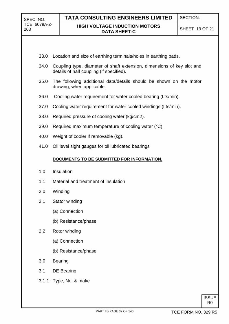
33.0 Location and size of earthing terminals/holes in earthing pads.
34.0 Coupling type, diameter of shaft extension, dimensions of key slot and details of half coupling (if specified).
35.0 The following additional data/details should be shown on the motor drawing, when applicable.
36.0 Cooling water requirement for water cooled bearing (Lts/min).
37.0 Cooling water requirement for water cooled windings (Lts/min).
38.0 Required pressure of cooling water (kg/cm2).
39.0 Required maximum temperature of cooling water (oC).
40.0 Weight of cooler if removable (kg).
41.0 Oil level sight gauges for oil lubricated bearings DOCUMENTS TO BE SUBMITTED FOR INFORMATION.
1.0 Insulation
1.1 Material and treatment of insulation
2.0 Winding
2.1 Stator winding
(a) Connection
(b) Resistance/phase
2.2 Rotor winding
(a) Connection
(b) Resistance/phase
3.0 Bearing
3.1 DE Bearing
3.1.1 Type, No. & make
PART IIB PAGE 37 OF 140

SPEC. NO. TCE. 6079A-Z-203
TATA CONSULTING ENGINEERS LIMITED SECTION:
HIGH VOLTAGE INDUCTION MOTORS DATA SHEET-C SHEET 20 OF 21
ISSUE R0
TCE FORM NO. 329 R5
3.1.2 Lubricant
3.1.3 Initial quantity
3.1.4 Relubricating interval
3.1.5 Relubricating quantity
3.1.6 Anticipated life
3.2 NDE Bearing
3.2.1 Type, No. & make
3.2.2 Lubricant
3.2.3 Initial quantity
3.2.4 Relubricating interval
3.2.5 Relubricating quantity
3.2.6 Anticipated life
4.0 Motor bearing lubrication system -
Self lubrication/Forced oil lubrication
4.1 Forced oil lubrication system (if provided)
a) Whether this is compatible with forced oil lubrication system of driven equipment.
If NO, furnish the following details for motor bearing
i)Type, make and specification of oil
ii) Flow rate (Ltrs/Sec)
iii) Pressure (Kg/cm2)
iv) Quantity of lube oil pump sets provided for each motor
v) Local control panel provided for forced oil lubrication system of each motor
vi) Make, type and name plate particulars of lube oil pumps & 415V, 3
PART IIB PAGE 38 OF 140

SPEC. NO. TCE. 6079A-Z-203
TATA CONSULTING ENGINEERS LIMITED SECTION:
HIGH VOLTAGE INDUCTION MOTORS DATA SHEET-C SHEET 21 OF 21
ISSUE R0
TCE FORM NO. 329 R5
phase, 50Hz motors.
vii) Filters - Make & type
5.0 Air temperature detector (Internal)
(CACA/CACW motor)
5.1 Type & make
5.2 Number
5.3 Number of contacts in each indicator
5.4 Contact rating at - 220V DC- 240V AC
6.0 Terminal box
6.1 Location of main terminal box viewed from non drive end (Right/Left)
7.0 No load current of motor at rated voltage & frequency (for each type of motor)
8.0 Limiting rotor temperature for determining safe stall time
9.0 Instruction Manual (Number of copies as per distribution schedule)
PART IIB PAGE 39 OF 140

SPEC.NO. TATA CONSULTING ENGINEERS LIMITED SECTION: C TCE.6079A-B-640-001
INSTRUMENTATION SYSTEM
SHEET OF 14 OF 4
1
ISSUE
R0
1.0 INSTRUMENTATION & CONTROL (I&C) SYSTEM COVERED UNDER SCOPE:
1.1 This specification details the minimum technical requirements for the instrumentation forming part of the Compressed Air System for Instrument air and Compressed Air System for Nitrogen generation plant Package for BPCL Petroleum Corporation Ltd. (BPCL) Mahul Refinery Project, India.
1.2 This specification along with General Engineering Specifications (GES) document no. TCE-6079A-580-IN-001 covers the general guidelines for design, supply, testing, inspection at CONTRACTOR’S works, erection/installation, testing, commissioning at site of the Instrumentation & Control System for the Compressed Air System for Instrument air and Compressed Air System for Nitrogen generation plant Package. Contractor shall be responsible to provide all instrumentation, controls and protective functions required for the safe operation of the systems and to comply with statutory regulations, applicable codes & standards.
1.3 The System Contractor shall be fully responsible for design, preparation of detailed engineering drawings, 3 D modelling, materials selection, sizing and selection of proper instruments, HAZOP study, manufacture, procurement, supply, inspection & expediting, delivery at site, erection/ installation including Quality Assurance, pre-commissioning and commissioning of all the instrumentation and control pertaining to the Nitrogen System on a turnkey basis.
1.4 Bidder shall, categorically, list out clause wise deviation to this specification and enclosed standards, if any, along with the offer. In the absence of which, it will be assumed that the Bidder is an total compliance to this specification.
1.5 In order to standardise with the plant instrumentation, the Contractor should supply the make of instruments according to the preferred vendor list attached with tender. For instruments not listed in the vendor list, makes for the same shall be subject to approval by BPCL.
1.6 Tests shall be done using calibrated instruments traceable to National or International standards.
1.7 The compliance with this specification does not relieve seller from his responsibility towards contractual obligations with regard to completeness, satisfactory operation and easy maintenance of the unit.
1.8 Instrument installation shall be suitable for the environmental conditions, which apply for the intended location of the unit as specified in unit requisition.
PART IIB PAGE 40 OF 140

SPEC.NO. TATA CONSULTING ENGINEERS LIMITED SECTION: C TCE.6079A-B-640-001
INSTRUMENTATION SYSTEM
SHEET OF 14 OF 4
2
ISSUE
R0
1.9 The Contractor shall meet all regulatory requirements, especially with respect to State Pollution Control Board (SPCB) and Central Pollution Control Board (CPCB).
1.10 The Contractor has to arrange all required test instruments, tools and tackles required during commissioning. Any instrument required to ascertain performance or guarantee figures shall also be supplied by the Contractor.
1.11 The following table indicates the scope matrix of the Vendor and Other Contractors:
Legends: D & S – Design and Supply E & C – Erection, Testing & Commissioning CS – Supervision of Erection, Testing and Commissioning X – Not applicable
ITEM DESCRIPTION SCOPE
VENDOR OTHERS D & S E & C CS D & S E & C CS
1. All field instruments and valves alongwith the erection hardware including anti-surge protection system, lube oil system, vibration and bearing temperature sensors and water cooling system for: (a) Instrument air compressor including dryer system
(i) Mounted on skid x x x (ii) Outside skid
x x By Other Contractor x
(b) Each air compressor (for Nitrogen plant)
(i) Mounted on skid x x x (ii) Outside skid
x x By Nitrogen Contractor
x
2. Junction boxes (JB) along with required erection hardware and all the accessories required such as mounting supports, cable glands, terminals for: (a) Instrument air compressor
(i) Mounted on skid x x x (ii) Outside skid (as applicable)
x x By Other
Contractor x
(b) Each air compressor (for Nitrogen plant) (i) Mounted on skid x x x
PART IIB PAGE 41 OF 140

SPEC.NO. TATA CONSULTING ENGINEERS LIMITED SECTION: C TCE.6079A-B-640-001
INSTRUMENTATION SYSTEM
SHEET OF 14 OF 4
3
ISSUE
R0
ITEM DESCRIPTION SCOPE
VENDOR OTHERS D & S E & C CS D & S E & C CS
3. Any PDB (distribution board) for further power distribution for Instrumentation within the Compressor plant battery limit for: (a) Instrument air compressor
(i) Mounted on skid x x x (ii) Outside skid (as applicable)
x x By Other Contractor x
(b) Each air compressor (for Nitrogen plant) mounted on skid x x x
4. Deriving any other power supply voltage levels (alongwith all the hardware such as converters etc) for: (a) Instrument air compressor
including dryer system x x x
(b) Each air compressor (for Nitrogen plant)
x x x
5. Completely wired control panels with all control system hardware and panel mounted accessories, alongwith control logic & interlocks for: (a) Instrument air compressor
including dryer system & anti-surge system
x x x
(b) Each air compressor including anti-surge system (for Nitrogen plant) x x x
6. The following signals shall be made available by the contractor on separate terminal strip in Instrument air compressor control panel for further wiring to boiler house DCS for monitoring: (a) Trip, On & Off status of the
compressor (b) Compressor Trouble (c) Compressor Discharge Air
pressure & temperature (d) Cooling water pressure,
temperature & flow
Supply, laying & termination of cables between these panels shall be in the scope of I&C erection contractor
PART IIB PAGE 42 OF 140

SPEC.NO. TATA CONSULTING ENGINEERS LIMITED SECTION: C TCE.6079A-B-640-001
INSTRUMENTATION SYSTEM
SHEET OF 14 OF 4
4
ISSUE
R0
ITEM DESCRIPTION SCOPE
VENDOR OTHERS D & S E & C CS D & S E & C CS
7. Trip status (2 Nos.) of each air compressor (for Nitrogen plant) shall also be made available for wiring to the existing air compressor panel.
Supply and laying of cables between these panels shall be in the scope of I&C erection contractor
8. All cables including cable glands (at both ends) including termination and accessories for the air compressors including anti-surge system and dryer system for instrument air compressor. This shall include the cables between the following, but not limited to the same: (i) Field instrument/ valves and junction boxes (ii) Junction boxes to control panel (iii) Power distribution cables to complete instrumentation system for compressed air
system within battery limit (iv) Instrument earthing (system earth) cables for the I&C system upto the respective
control panel. (a) Instrument air compressor including dryer system
(i) Mounted on skid x x x (ii) Outside skid
x x By Other Contractor x
(b) Each air compressor (for Nitrogen plant) (i) Mounted on skid x x x (ii) Outside skid x x By
Nitrogen Contractor
x
9. Cables including cable glands (at both ends) and other accessories for cabling between following: (Potential free contacts for the commands from control panel shall be made available by the contractor on separate terminal strip in the respective air compressor control panel. Similarly, status signals from the electrical panel shall be wired upto the terminal strip in the respective air compressor control panel by I&C erection contractor. Further wiring to controller inside the control panel shall be in the scope of contractor.)
(a) Instrument air compressor control panel and proposed extension 6.6 kV switchgear panel in DM plant (for instrument air compressor)
Wiring of commands and signals upto terminal strip in control panel
Supply, laying and termination of cables from the air compressor control panel to respective
PART IIB PAGE 43 OF 140

SPEC.NO. TATA CONSULTING ENGINEERS LIMITED SECTION: C TCE.6079A-B-640-001
INSTRUMENTATION SYSTEM
SHEET OF 14 OF 4
5
ISSUE
R0
ITEM DESCRIPTION SCOPE
VENDOR OTHERS D & S E & C CS D & S E & C CS
(b) Instrument air control panel and proposed MCC for new DM plant in DM plant switchgear room (For dryer and lube oil system of instrument air compressor)
electrical panel shall be in the scope of I&C erection contractor
(c) Air compressor control panels (for nitrogen plant) and proposed extension of existing aromatics 6.6 kV ABB board (for air compressor for Nitrogen plant)
10. All cables including cable glands (at both ends) and other accessories for cabling between the Air compressor control panel (for nitrogen plant) and Nitrogen MCC (for lube oil for air compressor for Nitrogen plant)
x x Supply, laying and termination shall be in the scope of Nitrogen plant contractor
11. Cable trays and conduits with all accessories and structural steel supports required for laying the cables for:
(a) Instrument air compressor including dryer system
(i) Mounted on skid x x x (ii) Outside skid
x x By Other Contractor x
(b) Each air compressor (for Nitrogen plant)
(i) Mounted on skid x x x (ii) Outside skid x x By
Nitrogen Contractor
x
12. All erection hardware including structural steel required for erection of all field instruments, cable trays/ GI conduits, panels, junction boxes etc. (a) Instrument air compressor including dryer system
(i) Mounted on skid x x x
PART IIB PAGE 44 OF 140
SPEC.NO. TATA CONSULTING ENGINEERS LIMITED SECTION: C TCE.6079A-B-640-001
INSTRUMENTATION SYSTEM
SHEET OF 14 OF 4
6
ISSUE
R0
ITEM DESCRIPTION SCOPE
VENDOR OTHERS D & S E & C CS D & S E & C CS
(ii) Outside skid x x By Other
Contractor x
(b) Each air compressor (for Nitrogen plant)
(i) Mounted on skid x x x (ii) Outside skid x x By
Nitrogen Contractor
x
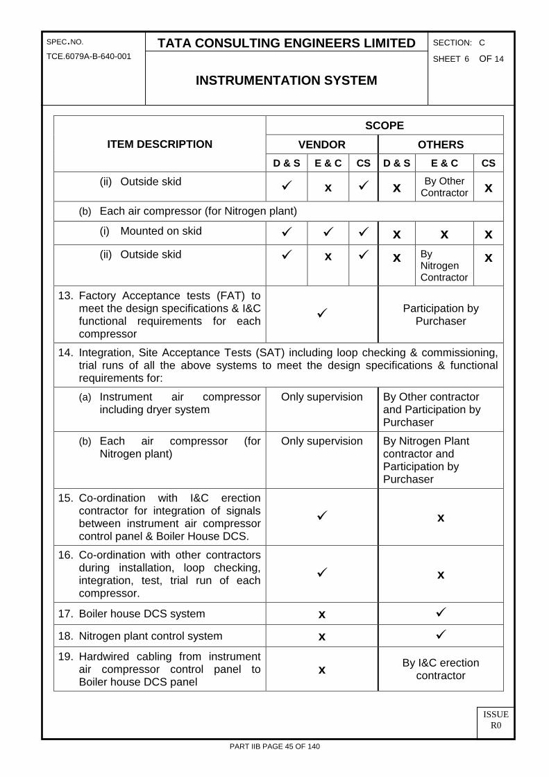
13. Factory Acceptance tests (FAT) to meet the design specifications & I&C functional requirements for each compressor
Participation by
Purchaser
14. Integration, Site Acceptance Tests (SAT) including loop checking & commissioning, trial runs of all the above systems to meet the design specifications & functional requirements for: (a) Instrument air compressor
including dryer system Only supervision By Other contractor
and Participation by Purchaser
(b) Each air compressor (for Nitrogen plant)
Only supervision By Nitrogen Plant contractor and Participation by Purchaser
15. Co-ordination with I&C erection contractor for integration of signals between instrument air compressor control panel & Boiler House DCS.
x
16. Co-ordination with other contractors during installation, loop checking, integration, test, trial run of each compressor.
x
17. Boiler house DCS system x
18. Nitrogen plant control system x
19. Hardwired cabling from instrument air compressor control panel to Boiler house DCS panel
x By I&C erection contractor
PART IIB PAGE 45 OF 140
SPEC.NO. TATA CONSULTING ENGINEERS LIMITED SECTION: C TCE.6079A-B-640-001
INSTRUMENTATION SYSTEM
SHEET OF 14 OF 4
7
ISSUE
R0
ITEM DESCRIPTION SCOPE
VENDOR OTHERS D & S E & C CS D & S E & C CS
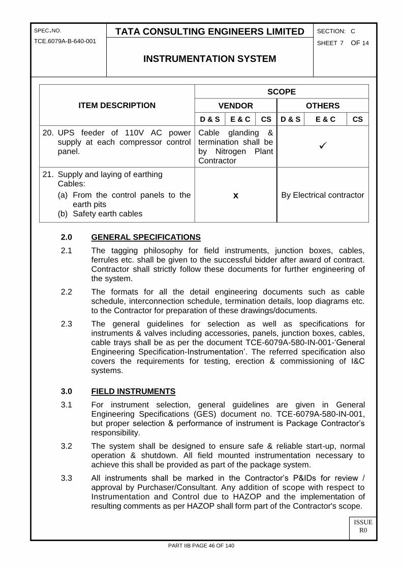
20. UPS feeder of 110V AC power supply at each compressor control panel.
Cable glanding & termination shall be by Nitrogen Plant Contractor
21. Supply and laying of earthing Cables: (a) From the control panels to the
earth pits (b) Safety earth cables
x By Electrical contractor
2.0 GENERAL SPECIFICATIONS 2.1 The tagging philosophy for field instruments, junction boxes, cables,
ferrules etc. shall be given to the successful bidder after award of contract. Contractor shall strictly follow these documents for further engineering of the system.
2.2 The formats for all the detail engineering documents such as cable schedule, interconnection schedule, termination details, loop diagrams etc. to the Contractor for preparation of these drawings/documents.
2.3 The general guidelines for selection as well as specifications for instruments & valves including accessories, panels, junction boxes, cables, cable trays shall be as per the document TCE-6079A-580-IN-001-‘General Engineering Specification-Instrumentation’. The referred specification also covers the requirements for testing, erection & commissioning of I&C systems.
3.0 FIELD INSTRUMENTS 3.1 For instrument selection, general guidelines are given in General
Engineering Specifications (GES) document no. TCE-6079A-580-IN-001, but proper selection & performance of instrument is Package Contractor’s responsibility.
3.2 The system shall be designed to ensure safe & reliable start-up, normal operation & shutdown. All field mounted instrumentation necessary to achieve this shall be provided as part of the package system.
3.3 All instruments shall be marked in the Contractor’s P&IDs for review / approval by Purchaser/Consultant. Any addition of scope with respect to Instrumentation and Control due to HAZOP and the implementation of resulting comments as per HAZOP shall form part of the Contractor's scope.
PART IIB PAGE 46 OF 140

SPEC.NO. TATA CONSULTING ENGINEERS LIMITED SECTION: C TCE.6079A-B-640-001
INSTRUMENTATION SYSTEM
SHEET OF 14 OF 4
8
ISSUE
R0
3.4 For all instruments supplied by the Contractor for the Compressed Air Systems, including any instruments not covered in this specifications, details for the same shall be submitted by the Contractor for review & approval by Purchaser/Consultant.
3.5 Instrument list Following list given is tentative. The basic minimum instrumentation requirements are shown in enclosed P&ID TCE.6079A-640-PI-1011 and TCE.6079A-640-PI-1012. Contractor shall provide instrumentation requirement over & above what is indicated for completion of the system.
SR. NO. SERVICE QUANTITY PROPOSED TYPE
Pressure Gauge and DP Gauge
1. For all services As per P&ID Bourdon type
Pressure Transmitter
2. For air and cooling water As per P&ID Capacitance type
Temperature Gauges
3. For Air and cooling water As per P&ID Bimetallic type (With thermowell)
4. Inside the Compressor
Filled-type with capillary extension
(mercury not acceptable)
Flow Transmitter
5.
(i) At the discharge of compressor
(ii) On cooling water supply header to the compressor
(iii) At outlet of dryer
As per P&ID Orifice with DP type
Transmitter
Temperature Measurement
6. Temperature measurement in cooling water and air As per P&ID
RTD element with temperature
transmitter along with thermowell
Control valve
7. For loading and unloading of the compressed air As per P&ID **
**- For type of Control valve selection; please refer the guidelines given in TCE-6079A-580-IN-001-‘General Engineering specification-Instrumentation’ and as per recommendation of manufacturer.
PART IIB PAGE 47 OF 140

SPEC.NO. TATA CONSULTING ENGINEERS LIMITED SECTION: C TCE.6079A-B-640-001
INSTRUMENTATION SYSTEM
SHEET OF 14 OF 4
9
ISSUE
R0
3.6 Specific Requirements Specific requirements for the compressor package (not covered in document TCE-6079A-580-IN-001-‘General Engineering specification-Instrumentation’) are given below.
3.6.1 Dew Point Analyser
Service : To detect moisture traces in air at the outlet of dryer unit in instrument air system.
Probe material : As per manufacturer’s recommendation Display on Transmitter : Required Accuracy : Vendor to State Power supply : 110V AC / 24 VDC Output signal : 4-20mA Accessories : All mounting hardware, SS name plate,
interconnecting cable between probe & transmitter and all other required accessories
3.6.2 Vibration sensors shall be provided as per API 670 in each compressor. For vibration measurement complete vibration monitoring system is not required. Only vibration sensor shall be provided with 4-20mA signal which will be wired to the respective compressor control panel for monitoring and control.
3.6.3 Temperature sensors shall be provided for measuring temperature of bearings in each compressor for monitoring and control in the compressor control panel.
3.6.4 Valve Positioners shall be non-HART. 3.6.5 All pneumatic tubing shall be of copper with PVC sheathing and
compression fittings shall be of brass.
4.0 CONTROL SYSTEM Each Compressor shall be provided with standalone microprocessor/ microcontroller based control system for control & monitoring. The compressor panel shall have necessary pushbuttons for compressor start/stop, selector switches, indicating lamps, hooter etc. for operation & monitoring of the compressor. There shall be an Operator Interface Unit mounted on the panel. The specifications for the Operator Interface Unit (OIU) shall be as per the guidelines/ specifications given in TCE-6079A-580-IN-001-‘General Engineering specification-Instrumentation’.
4.1 Operating Philosophy
PART IIB PAGE 48 OF 140

SPEC.NO. TATA CONSULTING ENGINEERS LIMITED SECTION: C TCE.6079A-B-640-001
INSTRUMENTATION SYSTEM
SHEET OF 14 OF 4
10
ISSUE
R0
4.1.1 Instrument Air Compressor Automatic load/unload shall be provided for the Instrument Air Compressor. This operation is achieved through signal from the pressure transmitter of air receiver. Compressor shall start unloading automatically when pressure in the air receiver goes above the set value and shall start loading automatically when receiver pressure goes below defined set value. If compressor unloads for longer duration (i.e. beyond defined duration) then, it shall stop the compressor automatically. The duration setting shall be adjustable through OIU. The control system shall also include anti-surge controls for the compressor. All necessary instruments & valves shall be provided to achieve the controls.
4.1.2 Air Compressors for Nitrogen System Automatic load/unload shall be provided for the Instrument Air Compressor. This operation is achieved through signal from the pressure transmitter of air on the discharge line of each compressor. Compressor shall start unloading automatically when pressure in the discharge line goes above the set value and shall start loading automatically when discharge pressure goes below defined set value. If compressor unloads for longer duration (i.e. beyond defined duration) then, it shall stop the compressor automatically. The duration setting shall be adjustable through OIU. The control system shall also include anti-surge controls for the compressor. All necessary instruments & valves shall be provided to achieve the controls.
4.1.3 Compressor can be started and stopped using pushbuttons provided on the panel in Auto as well as manual mode.
4.1.4 All the control logic/ interlocks required for the safe & reliable operation of the system shall be provided in the controller.
4.2 Alarms 4.2.1 The following list of alarms is indicative. Vendor shall provide all the alarms,
which are necessary for safe and reliable monitoring & operation of the system. The list of alarms shall be submitted by Contractor for review & approval of Purchaser/Consultant during detailed engineering. (a) All the alarms as indicated in the attached P&ID for ‘Compressed Air
system’ (b) Controller Trouble (c) Tripping of compressor (d) High vibration (e) High bearing temperature (f) Air receiver pressure high (g) Air receiver pressure low
PART IIB PAGE 49 OF 140

SPEC.NO. TATA CONSULTING ENGINEERS LIMITED SECTION: C TCE.6079A-B-640-001
INSTRUMENTATION SYSTEM
SHEET OF 14 OF 4
11
ISSUE
R0
(h) Lube oil pressure low (i) Air temperature at discharge of inter stage of compressor high (j) Air temperature at discharge of compressor high (k) Lube oil temperature high (l) Flow of cooling water return compressor low (m) Exceeding of set points for all the parameters (n) Healthiness of any other derived power supply (such as 24V DC) shall
be monitored and alarm shall be annunciated under abnormal conditions.
4.2.2 1 no. of hooter shall be provided for the sound identification of the Alarm conditions.
4.2.3 The detailed alarm description shall be available in the alarm screens on the OIU. Facility for the Test / Acknowledge / Reset pushbuttons for the alarms shall also be provided in the OIU.
4.3 Dryer System Automatic switching shall be provided between active and regeneration tower of the dryer. Contractor shall provide complete instrumentation including sequential interlocks and alarms, which are necessary for safe and reliable operation of the dryer system. Push buttons, timers, indicating lamps, switches shall be provided on front facia of the dryer panel.
5.0 POWER SUPPLY 110V AC power supply at shall be made available to each compressor control panel of the compressor. Further power supply distribution within the compressor battery limit including power supply for dryers, anti-surge system shall be done by Contractor. Any other voltage required for the I&C system for the plant shall be derived by the Contractor using redundant power supply units. All distribution feeders shall be provided with circuit breakers/isolating switches for isolation.
6.0 INTERFACES WITH OTHER SYSTEMS: 6.1 The following signals shall be hardwired from the Instrument Air
Compressor control panel to the Boiler House DCS for monitoring: (a) Trip, On & Off status of the compressor (b) Compressor Trouble (c) Compressor Discharge Air pressure & temperature (d) Cooling water pressure, temperature & flow.
6.2 All above signals shall be made available by the Contractor on separate terminal strip in the Instrument air compressor control panel for further wiring to boiler house DCS.
PART IIB PAGE 50 OF 140

SPEC.NO. TATA CONSULTING ENGINEERS LIMITED SECTION: C TCE.6079A-B-640-001
INSTRUMENTATION SYSTEM
SHEET OF 14 OF 4
12
ISSUE
R0
6.3 Additionally trip status (2 Nos.) of each of the Air Compressors (for nitrogen generation plant) shall be kept wired upto the terminals in the respective compressor control panel. This signal shall be used for wiring to the existing compressor panel.
7.0 DOCUMENTS TO BE SUBMITTED BY CONTRACTOR: 7.1 The BIDDER shall ensure the following documents are prepared and
submitted along with bid: (a) Acceptance to the vendor list (signed and stamped copy). (b) All sheets of Section C signed and stamped. (c) List of I&C deviations (if any) (d) Bidder shall indicate the electrical load of the I&C system for the air
compressors in his offer for 110 V AC UPS power supply.
7.2 The CONTRACTOR shall submit the following drawings / documents for each compressor & dryer after award of contract:
Sl. No. Details
1. Instrument list indicating tag numbers, Make, Model No, Service, type of Instrument.
2. Input/ Output list (with all the details like tag nos., service description, units, alarm /indication requirement etc)
3. Alarm list indicating the alarm/ set point value.
4. Total power consumption & air consumption for the I&C system.
5. Data sheets for all the instruments, cables, panels, junction boxes alongwith the original catalogues.
6. Data sheets/ documents, catalogues & QAP for the dedicated power supply units (if provided) along with load calculations
7. Sizing calculation sheets for control valves, flow elements.
8. Loop schematics for all closed & open loops.
9. Installation sketches (hook-ups) along with detailed Bill of Material.
10. Functional write-up of Control System
11. Following drawings / documents for the Control System for the Plant
(a) Make, Model No., Catalogues of the control system
(b) I/O list indicating I/O assignment
PART IIB PAGE 51 OF 140

SPEC.NO. TATA CONSULTING ENGINEERS LIMITED SECTION: C TCE.6079A-B-640-001
INSTRUMENTATION SYSTEM
SHEET OF 14 OF 4
13
ISSUE
R0
Sl. No. Details
(c) Sequence & interlock description & control logic diagrams
(d) Details of interfacing to other control systems
(e) Operating manual
(f) Hardware and software manuals for application & engineering software.
12. Following drawings for Operator Interface Unit:
(a) Listing of alarm messages
(b) Catalogues
(c) Graphic Screen Layout
(d) Control Schemes
(e) Details of Software Package in the Operator Interface Unit indicating various functions & facilities available
13. The following drawings/ documents shall be submitted for the Control Panels:- (i) Front facia /rear arrangement layout showing all instruments
with cut-outs, bezel dimensions, construction details, foundation details, interior G.A. drawings and control panel dimensions.
(ii) Internal wiring & control wiring diagrams indicating termination details of each component.
(iii) Bill of Material (B.O.M) indicating tag No, quantity, service & model no. of each instrument/item.
14. Power Supply Distribution Scheme for the entire I&C system indicating and type, rating & quantity of each feeder.
15. Junction box schedule & air manifold schedule
16. QAPs for all items like instruments, panels, junction boxes & cables.
17. Test procedure for FAT & SAT
18. Heat load and Power consumption for A.C. & D.C. loads.
19. Instrument location drawing (showing instrument location, JB location, panel location etc)
PART IIB PAGE 52 OF 140

SPEC.NO. TATA CONSULTING ENGINEERS LIMITED SECTION: C TCE.6079A-B-640-001
INSTRUMENTATION SYSTEM
SHEET OF 14 OF 4
14
ISSUE
R0
Sl. No. Details
20. Earthing diagrams indicating both safety & system earth requirements
21. Cable tray layouts
22. Cable Schedules and Interconnection cable schedules.
23. ‘As Built’ drawings.
24. All certificates including calibration reports, type test & routine test certificates etc.
25. Spare parts:
(a) Mandatory spare part list (for all equipment items, instruments) (b) Recommended spare list for 2 years continuous operation (c) Spares being supplied alongwith model nos., part nos. &
quantity 26. Instruction manual for installation, operation, start-up and
maintenance (per instrument type). 27. System operation and maintenance manual
PART IIB PAGE 53 OF 140

PART IIB PAGE 54 OF 140

TATA CONSULTING ENGINEERS LIMITED SECTION: Facing Page
TCE-6079A-580-IN-001 General Engineering Specification for Instrumentation
SHEET i OF i
ISSUE R0
FORM NO. 120 R2
GENERAL ENGINEERING SPECIFICATION - INSTRUMENTATION
PART IIB PAGE 55 OF 140

TATA CONSULTING ENGINEERS LIMITED
SECTION: Write-Up
TCE-6079A-580-IN-001 General Engineering Specification for Instrumentation
SHEET 1 OF 79
File Name: GEC_I&C
ISSUE R0
FORM NO. 120 R2
1.0 GENERAL
1.1 This specification covers the minimum technical requirements and essential particulars for the design of the I&C systems included in the Package Unit Vendor‟s scope as identified in this specification. The specification contains the basic requirements for the engineering, supply & installation of the Instrumentation for the Package Unit.
1.2 The document shall be read in continuation to the scope of work detailed in document for the I&C system for the respective for the Package Unit.
2.0 CODES & STANDARDS
2.1 The design, manufacture, inspection of all equipment and systems covered herein shall conform to the latest editions of codes and standards mentioned below. Where a conflict between the codes might exist, the most stringent requirements shall govern.
ANSI (American National Standards Institute) ANSI-MC 96.1 Temperature measurement - Thermocouples ANSI 70.2 Control Valve Seat Leakage classification ANSI B 16.34 Valves - flanged, threaded and welding end ANSI B-16.11 Dimensions of fittings ANSI 16.36 Orifice Flanges ASME (American Society of Mechanical Engineers) ASME PTC 19.2 ASME Performance test codes - supplement on
instruments and apparatus, Part 2 pressure measurement
ASME PTC 19.3 ASME Performance test codes - supplement on instruments and apparatus, Part 3 temperature measurement
ASME PTC 19.5 Instrument and apparatus for flow measurement API (American Petroleum Institute) API RP-520 Design & Installation of Pressure Relieving
Systems in Refineries
API RP 521 Guide for Pressure Relieve and Depressurising Systems
API RP 526 Flanged Steel Safety Relief Valves
PART IIB PAGE 56 OF 140

TATA CONSULTING ENGINEERS LIMITED
SECTION: Write-Up
TCE-6079A-580-IN-001 General Engineering Specification for Instrumentation
SHEET 2 OF 79
File Name: GEC_I&C
ISSUE R0
FORM NO. 120 R2
API RP 527 Commercial Seat Tightness of safety Relief Valves with Metal to Metal Seats
RP551- Part -1 Process Measurement Instrumentation RP552 Transmission Systems RP553 Refinery Control Valves RP554 Process Instrumentation and Control RP555 Process Analyzers IS (Indian Standards) IS - 2148 Enclosure for instruments in hazardous area IS - 2848 Industrial Platinum resistance thermometer IS - 3624 Pressure & Vacuum Gauges IS – 5831 PVC insulation & sheath of electric cables IS - 7358 Specifications for Thermocouples IS - 8748 Thermocouple Compensating Cables IS-13947 Protection Class for Enclosure, Cabinets, Control
Panels and Desks IS-1554-1988 PVC Insulated Heavy Duty Electrical Cables. IEC (International Electro-Technical Commission) IEC 60584 Thermocouples IEC 60751 Industrial Platinum Resistance Thermometer
Sensors. IEC 60332 Tests on Electric Cables under Fire Conditions I EC 60079-0 Electrical apparatus for Explosive Gas atmosphere IEC 60079-1 Construction & Verification Test of Flameproof
Enclosure for Electrical Apparatus. IEC 60079-2 Electrical Apparatus for Explosive gas Atmosphere
- Electrical Apparatus Type of Protection "P" IEC 60079-7 Electrical Apparatus for Explosive gas
Atmosphere, Part 7: Increased Safety EEx'e' IEC 60079-8 Classification of Maximum Surface Temperature IEC 60079-11 Electrical Apparatus for Explosive gas
Atmosphere, Part 11: Construction & Test of Intrinsically Safe and Associated Apparatus.
PART IIB PAGE 57 OF 140

TATA CONSULTING ENGINEERS LIMITED
SECTION: Write-Up
TCE-6079A-580-IN-001 General Engineering Specification for Instrumentation
SHEET 3 OF 79
File Name: GEC_I&C
ISSUE R0
FORM NO. 120 R2
IEC 60079-16 Electrical Apparatus for Explosive gas Atmosphere - Artificial Ventilation for Protection of Analyzer houses
IEC60801 Electromagnetic compatibility for Industrial Process Measurement and Control equipment.
IEC 61131-3 (1993-03)
Programmable controllers – Part 3, Programming Languages
IEC 61131 Programmable controllers BS (British Standards) BS EN ISO 5167-1
Measurement of fluid flow by means of pressure differential devices
BS 5308, Part 1 BS 5308, Part 2
Specification for Polyethylene insulated cables. Specification for PVC insulated cables.
BS 7244 Flame Arrestors/ Breather Valves ISA (Instrument Society of America) ISA S12.4 Instrument purging for reduction of hazardous area
classification ISA S 5.1 Instrumentation symbols and identification ISA S-5.2 Graphic symbols for Distributed Control/Shared
Display Instrumentation Logic and Computer system
ISA S7.3 Quality standard for instrument air ISA S18-1 Alarm Sequence S-75.01 Flow equations for sizing control valves. S-75.04 Face to Face Dimension for Flangeless Control
Valve Body NACE Material resistance to sulfide stress cracking
2.2 Notwithstanding the recommendations and stipulations of the codes and standards mentioned above, the requirement of this specification shall be deemed minimum and shall be complied with fully.
2.3 All codes and standards referred shall be the latest version on the date of offer made by the Bidder unless otherwise indicated.
3.0 BASIC DESIGN CRITERIA
3.1 All field instruments being offered/ supplied should have been operating
PART IIB PAGE 58 OF 140

TATA CONSULTING ENGINEERS LIMITED
SECTION: Write-Up
TCE-6079A-580-IN-001 General Engineering Specification for Instrumentation
SHEET 4 OF 79
File Name: GEC_I&C
ISSUE R0
FORM NO. 120 R2
satisfactorily in a hydrocarbon industry like Refinery, Petrochemical and Gas Processing Plant under similar process conditions for at least 4000 hrs. Proven Track Record (PTR) for all field instruments shall be considered for minimum of 4000 hours and for system oriented items such as Analysers, PLC, controllers etc., the same shall be minimum 1 year.
3.2 The instrumentation selected for the unit shall be rugged in design. Prototype design or equipment of experimental nature or design undergoing testing etc., shall not be selected and supplied.
3.3 All I&C equipment shall be fully tropicalised. All instruments shall be suitable for use in hot, humid, tropical & dusty climate in which corrosive gases may be present. The instruments shall be suitable for outdoor installations, considering temperature, humidity etc., as per the data given elsewhere in the tender document. All instruments, their supports including all mounting hardware, manifolds, and fittings shall be suitable for the application. All external surfaces shall be suitably treated to provide protection against the corrosive plant atmosphere.
3.4 The design of electronic instruments shall be in compliance with the electromagnetic compatibility requirements as per IEC 801 “Electromagnetic compatibility for Industrial Process Measurement & Control Equipment”.
3.5 All instruments and control devices located on control panels shall be of miniaturised design, suitable for modular flush mounting on control panels with front draw out facility and flexible plug-in connections at the rear.
3.6 Field mounted electrical and electronic instruments shall be weatherproof to IP-65. All instruments of submersible type shall be protected to IP-68. The instruments shall be suitable for the area classification.
3.7 The standard signals for measurements & control signals shall be 4-20 mA.
3.8 Wherever local loop powered repeat indication is required, the second entry of the transmitter shall be used to wire the local indicator in the loop. Additional terminals within the transmitter shall be taken for loop indication.
3.9 All transmitters shall be SMART type with HART protocol unless otherwise indicated. All transmitters shall have local digital indication (LCD).
PART IIB PAGE 59 OF 140

TATA CONSULTING ENGINEERS LIMITED
SECTION: Write-Up
TCE-6079A-580-IN-001 General Engineering Specification for Instrumentation
SHEET 5 OF 79
File Name: GEC_I&C
ISSUE R0
FORM NO. 120 R2
3.10 Valve positioners shall be conventional type unless otherwise indicated, operating on input signal of 4-20 mA.
3.11 Instrumentation for Hazardous Areas
3.11.1 Certified intrinsically safe equipment shall be used, in general, in hazardous area. In case intrinsically safe equipment is not available, flameproof/ex-proof enclosures shall be provided.
3.11.2 Intrinsically safe, flameproof instruments/ enclosures shall be certified to the specified hazardous area by a statutory body like FM, UL, CENELEC, CMRI etc. In addition for instruments installed in hazardous area, CCOE (Chief Controller of Explosives) certification shall be complied with. CCOE Certificates for all instruments installed in hazardous area shall be provided by the vendor. This Vendor shall ensure that CCOE certification for instruments is available before mechanical completion of the plant.
3.11.3 For hazardous areas, instrument input/output signals to control room shall be as follows:
Transmitters (2 wire ) Intrinsically safe Transmitters (4 wire) Flameproof/Ex-proof with signal
output intrinsically safe Field switches Flameproof/Ex-proof (Switch
contacts to be wired through safety barrier to have IS signal)
RTD & Thermocouple Flameproof-Ex-proof/ Intrinsically safe
Solenoid valves Flameproof/Ex-proof Limit Switches Flameproof-Ex-proof/ Intrinsically
safe Proximity Switches NAMUR type
3.11.4 Intrinsically Safe System Requirements
(a) Safety barriers with galvanic isolation (active barriers) shall be used to achieve intrinsically safe signals. The intrinsic safe barrier shall be certified for intrinsic safety by any statutory authority. Intrinsic safe barrier shall be provided also for potential free contacts wired from switches in hazardous areas.
(b) Barriers must be selected based on entity concept. Cable parameters shall also be considered while matching entity parameters.
PART IIB PAGE 60 OF 140

TATA CONSULTING ENGINEERS LIMITED
SECTION: Write-Up
TCE-6079A-580-IN-001 General Engineering Specification for Instrumentation
SHEET 6 OF 79
File Name: GEC_I&C
ISSUE R0
FORM NO. 120 R2
(c) Each input & output in a loop shall have separate barrier. No barrier shall be shared between two loops or inputs/outputs.
(d) Any intrinsically safe loop requiring any device to be connected in the hazardous side permanently or temporarily shall also be intrinsically safe.
(e) Following concepts shall be applied for protection if intrinsically safe or flameproof concept cannot be applied.
i. Increased safety method. ii. Pressurization method.
3.12 For junction boxes mounted outdoors, IP 65 protection class shall be provided. For junction boxes mounted indoors, IP 52 protection class shall be provided. Junction boxes and cable glands for ex-proof instruments (if any) shall be ex-proof.
3.13 All field mounted / panel mounted selector and push button switches shall be installed inside suitable enclosure with proper protection by cover to avoid accidental operation. In case if Emergency stop switches are wired directly to the MCC, such shall have an additional set of potential free contact to be wired to the DCS system.
3.13.1 Analog signal multipliers & relays shall be provided for multiplication of analog signals & potential free contacts respectively in panels.
3.14 For all pressure gauges, level gauges etc. drain & vent connection shall be provided using same piping class valves & components.
3.15 All valve manifolds for instruments shall be fabricated at site.
3.16 All line or equipment mounted instruments like control valves, pressure relief valves, thermowells, orifice flanges, level instruments, pressure gauges etc., installed on pipes and vessels under IBR shall be certified by IBR or their authorised representative. They shall comply to the special Piping Material Specification requirements specified elsewhere in the Tender document. Further installation items on the IBR lines like syphon, condensate chambers, pipe and pipe fittings, steam tracing fittings shall have IBR certification.
3.17 All transmitters (flow, level, pressure, temperature) shall be of SS-316 MOC minimum for body, flanges and all wetted parts. For Superior material shall be provided if process condition demands, subject to TCE/BPCL‟s approval.
3.18 Enclosures of field transmitters and switches shall be die cast aluminium with epoxy painting as a minimum.
PART IIB PAGE 61 OF 140

TATA CONSULTING ENGINEERS LIMITED
SECTION: Write-Up
TCE-6079A-580-IN-001 General Engineering Specification for Instrumentation
SHEET 7 OF 79
File Name: GEC_I&C
ISSUE R0
FORM NO. 120 R2
3.19 For all instruments in sour service, all materials of construction shall meet the requirements specified in NACE MR 01-75 latest edition. NACE certification shall be provided for all such instruments. In addition, any other requirements if specified in respective piping material specifications, shall also be complied.
3.20 Material of construction for solenoid valves shall be SS 316 i.e. body & wetted parts.
3.21 All pneumatic tubing shall be of SS 316, unless otherwise specified.
3.22 For high pressure services, end connections shall be as per PMS.
3.23 The rating of flanges for instruments shall be 300# as per ANSI. Higher rating shall be provided as per the piping material specification for the application.
3.24 Cable entry for instruments shall generally be ½” NPT (F).
3.25 All instruments/devices shall be immune to interference due to normal walkie-talkies with output of 1 Watt UHF.
3.26 All instruments mounted outdoors shall be provided with FRP canopy for protection from top & sides.
3.27 All instruments shall be provided with SS tag plate.
3.28 Engineering units to be used for various measurements shall be as follows:
Measured variable Unit of measurement Temperature Deg C Pressure & Differential Pressure mm of WC, kg/cm2(g),
Vacuum pressure mm of Hg, mm of WC, kg/cm2a
Flow
Steam Flow Kg/hr, T/hr
Liquid Flow, Volume Liquid Flow, Mass
m3/hr MT/day, kg/hr Gas Flow, Volume
Gas Flow, Mass m3/hr T/day, kg/hr
Level % level, mm
PART IIB PAGE 62 OF 140

TATA CONSULTING ENGINEERS LIMITED
SECTION: Write-Up
TCE-6079A-580-IN-001 General Engineering Specification for Instrumentation
SHEET 8 OF 79
File Name: GEC_I&C
ISSUE R0
FORM NO. 120 R2
Analysis %, ppm Density kg/m3 Conductivity S/cm, u/cm pH measurement pH
3.29 Power Supply
3.29.1 Primary source of power shall be 110 V AC + 10%, 50 Hz, UPS power. 3.29.2 The voltage levels shall be as specified in the respective package
specifications. 3.29.3 24 VDC power supply required shall be derived by the bidder using 24 V
DC power supply units in redundant configuration with diode Or-ing. The maximum loading of the power supply units at full load shall not exceed 75%.
3.29.4 Instrument power circuits shall be individually protected with the help of MCBs.
3.29.5 Electric actuators for valves & dampers shall operate on 415 V AC, 3 Ph, 50 Hz.
3.30 Air Supply
3.30.1 Instrument air shall be made available at the battery limits of the package. Instrument air quality shall be as per ISA-S7.3
3.30.2 Instrument dry air at pressure of 5/6/7 kg/cm2(g) (Min/Nor./Max), at normal temperature of 45°C and dew point at -40°C at atmospheric pressure shall be available, wherever envisaged.
3.30.3 Pneumatic instruments shall operate on air supply of 1.4 kg/cm2 and shall have transmission & output signal of 0.2 to 1.0 kg/cm2.
3.30.4 Valve actuators shall be sized for min. 4 kg/ cm2.
3.31 Alarm Philosophy
3.31.1 Adequate alarms shall be provided to give audible & visual warning of any package malfunction.
3.31.2 All package alarms including trip alarms shall be annunciated on the local panels.
3.31.3 Common trip alarm contacts for the package shall be provided for remote annunciation.
3.31.4 Wherever, hardwired Alarm Annunciator is provided, the system shall be microprocessor based with audio & visual alarms. Electronic hooter shall
PART IIB PAGE 63 OF 140

TATA CONSULTING ENGINEERS LIMITED
SECTION: Write-Up
TCE-6079A-580-IN-001 General Engineering Specification for Instrumentation
SHEET 9 OF 79
File Name: GEC_I&C
ISSUE R0
FORM NO. 120 R2
be provided for the audio alarm.
3.31.5 The colour of windows shall be white with black letters for general purpose alarms and red with black letters for trip alarms.
3.31.6 The size of windows shall be minimum 45 mm (H) x 45 mm (L). 3.31.7 For alarm annunciators mounted in safe area, split type annunciator
shall be provided with windows mounted on front of panel and electronic module inside the panel. Acknowledge, test & reset pushbuttons shall be provided.
3.31.8 For hazardous areas, the alarm annunciator shall be ex-proof. 3.31.9 The design of the alarm annunciator system shall be such that transient
alarm time of less than 330-millisecond duration shall be automatically rejected.
3.31.10 Alarm Annunciator sequence logic shall in general be in accordance with ISA S 18.1.
3.31.11 Cluster LED type lamps shall be provided in the windows. 3.31.12 Fault contacts actuating alarms shall be normally closed, energized and
shall open on the abnormal condition. 3.31.13 Each annunciator cabinet shall have 20% spare windows minimum, for
future use.
4.0 GENERAL SPECIFICATION OF INSTRUMENTS
4.1 The general guidelines for provision of the instruments & the specifications for the same are as given below. This specification provides only the qualitative specifications of commonly used instruments. Instruments not covered in this specification shall be submitted by the Vendor for approval. Vendor shall be fully responsible for design, material selection, sizing, selection of the proper instruments for their system.
4.2 Pressure Measurements
4.2.1 Pressure Gauges
(a) Measuring range selected shall be such that normal indication is between 60% to 80% of range. However, maximum operating value shall not be more than 90% of range.
Type : Direct Reading
Sensing Element : Bourdon/ Diaphragm/ Capsule
PART IIB PAGE 64 OF 140

TATA CONSULTING ENGINEERS LIMITED
SECTION: Write-Up
TCE-6079A-580-IN-001 General Engineering Specification for Instrumentation
SHEET 10 OF 79
File Name: GEC_I&C
ISSUE R0
FORM NO. 120 R2
Casing : SS 316
Movement : SS 304
Glass : Shatterproof
Dial size : 150 mm
Range : Vendor to State
Overrange Protection : 1.3 times the max. scale reading
Wetted Parts (including accessories like syphon, snubber, valve manifolds)
: Minimum – SS 316. Superior material to be considered if process condition demands, subject to TCE/BPCL‟s approval.
Diaphragm seals : Required for viscous slurry applications, for fluids which tend to crystallize and for corrosive fluid lines (acid, alkali etc.)
Accuracy : + 1.0 % of full scale Upto + 2.0% of full scale for D.P.gauges
Accessories : (a) Blow-out Discs for pressure gauges
(b) Syphons for services above 75oC (c) Snubbers where pulsation occur
in the process. (d) 2-valve manifold (valve manifold
not required for gauges with diaphragm seal)
(b) Solid front gauges shall be provided for ranges above 100 kg/ cm2. (c) All vacuum & draft gauges shall cover the negative pressure as well
as the positive pressure as the case may be. Draft gauges shall be required to have an accuracy of + 3% of full scale or better. The gauges shall be capable of withstanding pressures or vacuum equivalent to 100% over range.
4.2.2 Pressure Transmitters
For pressure transmitters, the normal operating pressure shall be within 40 % to 70 % of the calibrated scale range. Type : 2-wire, SMART with local LCD
indication
PART IIB PAGE 65 OF 140

TATA CONSULTING ENGINEERS LIMITED
SECTION: Write-Up
TCE-6079A-580-IN-001 General Engineering Specification for Instrumentation
SHEET 11 OF 79
File Name: GEC_I&C
ISSUE R0
FORM NO. 120 R2
Enclosure : Die cast Aluminum with epoxy painting
Operating principle : Capacitance type
Wetted Parts (including accessories)
: Minimum – SS 316. Superior material to be considered if process condition demands, subject to TCE/BPCL‟s approval. For pure hydrogen service gold plated diaphragm shall be used.
Accuracy : + 0.075 % of span
Stability : + 0.5% of upper range for 1 year
Output : 4-20 mA with HART protocol
External Zero & span adjustment
: Required
Features : Transmitter shall diagnose both an input sensor failure and transmitter electronics failure. It shall also be capable of transmitting sensor &/or electronics failure to the host system (e.g. DCS / PLC).
Overrange protection : 130% of maximum range. Transmitters shall be able to withstand the line hydrotest pressure. Vacuum pressure transmitters shall be capable of withstanding full vacuum regardless of range.
Cable entry : ½” NPT (F)
Test terminals : Required for field testing without disconnecting local indicator
Diaphragm seal : Required for viscous, slurry applications or for fluids which tend to crystallize and for corrosive fluid lines (acid, alkali etc.). Capilliary of minimum 3 metres long shall be provided for remote seals, Longer length shall be provided as required.
Flange Material & Rating : As per Piping Material Specifications
Accessories (a) Syphons for services above 75oC, (b) Snubbers for where pulsation
occur in the process
PART IIB PAGE 66 OF 140

TATA CONSULTING ENGINEERS LIMITED
SECTION: Write-Up
TCE-6079A-580-IN-001 General Engineering Specification for Instrumentation
SHEET 12 OF 79
File Name: GEC_I&C
ISSUE R0
FORM NO. 120 R2
(c) Gauge savers for protecting gauges from overrange pressure, wherever applicable
(d) 2-valve manifold (not required for transmitters with diaphragm seal), and SS name plate
4.2.3 Pressure Switches
(a) Pressure Transmitters with DCS/PLC switching shall be used instead of Pressure Switches. In case use of pressure switches are unavoidable approval is required from Purchaser/Consultant.
(b) For pressure, the set points shall fall within 30% to 70% of the scale range selected.
(c) Material and sensor selection shall be on the same guidelines mentioned under pressure gauges.
(d) The switch differential shall be selected as per operating conditions.
Type : Non-indicating type
Casing : Die cast aluminum casing with epoxy painting
Repeatability : + 1 % of full scale reading
Micro switch contacts
: 2 Nos. SPDT contacts rated 5A at 240V AC.
Overrange protection : 25% above maximum pressure for switches with range up to 150 kg/cm2 and 15% above maximum pressure for switches with range above 150 kg/cm2 as per IS 3624
Accessories : Syphons for services above 75oC, snubber for high pulsation applications, 2-valve manifold, and SS name plate
4.3 Level Measurement
4.3.1 Level Gauges
(a) Reflex/Transparent Level Gauges
i. The visible range of level gauge shall be selected to cover the operating level or the operating range of level transmitters provided for the vessel. Maximum length of one gauge glass
PART IIB PAGE 67 OF 140

TATA CONSULTING ENGINEERS LIMITED
SECTION: Write-Up
TCE-6079A-580-IN-001 General Engineering Specification for Instrumentation
SHEET 13 OF 79
File Name: GEC_I&C
ISSUE R0
FORM NO. 120 R2
shall not exceed 1500 mm. ii. Gauge glasses shall be stacked to cover the complete height of
the tanks. Type : (a) Reflex type gauge glass for clean
& colourless liquids (b) Transparent type for dirty,
viscous, colourd liquids (c) Tubular gauge glasses, in
general, shall not be used. Protective cover : Required, SS Automatic ball check valve : Required, off-set type Illuminator : Required wherever plant illumination Is
not adequate. Power supply for the same shall be 240 V AC, 50 Hz. The illuminators shall be suitable for the specified hazardous area classification.
Mica Shield : Required for the transparent gauge glass for corrosive, condensate etc. applications.
Frost Protection : For very low temperature liquids Excess flow check valves : Required Heating jacket/Steam tracing
: Required in case of crystallizing or viscous liquids, as required.
MOC : Toughened borosilicate glass Vent & drain valves : Required, ½” drain valve with plug &
½” vent plug
(b) Magnetic Type Level Gauge
Magnetic type level gauges shall be provided where the liquid attacks glass, is aggressive or contaminated i.e. where gauge glasses are not safe Type : Side mounted Magnetic type liquid
level gauge with red PP follower capsule/ bi-colour rotating flapper
Material of Float Chamber & Float (including all other wetted parts)
: Minimum – SS 316. Superior material to be considered if process condition demands, subject to TCE/BPCL‟s approval.
Calibrated scale : White powder coated Aluminium with epoxy painting.
PART IIB PAGE 68 OF 140

TATA CONSULTING ENGINEERS LIMITED
SECTION: Write-Up
TCE-6079A-580-IN-001 General Engineering Specification for Instrumentation
SHEET 14 OF 79
File Name: GEC_I&C
ISSUE R0
FORM NO. 120 R2
Vent & Drain : Required, ½” drain valve with plug & ½” vent plug
Process Connection : Flanged (c) On low temperature services with liquids having very high vapour
pressure at ambient temperatures safety valves shall be provided on the vent connection of the gauge glass.
4.3.2 Level Switch
Type : Magnetic type top mounted float actuated level switch.
Material of float & float stem including all other wetted parts
: SS316. Superior material to be considered if process condition demands, subject to TCE/BPCL‟s approval.
Mounting : External with standpipe with side-side connections.
Operating Differential : Adjustable Housing : Die cast aluminum with epoxy painting Switches : Microswitch, 2 Nos. SPDT
4.3.3 Level Transmitters
(a) D.P. type Level Transmitter
Type : 2-wire, SMART type with local LCD indication
Enclosure : Die cast Aluminium with epoxy painting
Operating principle : Capacitance type
Wetted Parts (including accessories)
: Minimum – SS 316. Superior material to be considered if process condition demands, subject to TCE/BPCL‟s approval. For pure hydrogen service gold plated diaphragm shall be used.
Accuracy : + 0.075 % of span
Output : 4-20 mA with HART protocol
Diaphragm seal (Refer Note-1 below)
: For applications which are viscous, slurries or corrosive liquids. Minimum 3 m length of capillary shall be provided for remote seals, longer length shall be provided as required.
PART IIB PAGE 69 OF 140

TATA CONSULTING ENGINEERS LIMITED
SECTION: Write-Up
TCE-6079A-580-IN-001 General Engineering Specification for Instrumentation
SHEET 15 OF 79
File Name: GEC_I&C
ISSUE R0
FORM NO. 120 R2
Features : Transmitter shall diagnose both an input sensor failure and transmitter electronics failure. It shall also be capable of transmitting sensor &/or electronics failure to the host system (e.g. DCS / PLC).
Test terminals : Required for field testing without disconnecting local indicator
Accessories : (a) 5-valve manifold for D.P.Transmitter (Not required for transmitters with diaphragm seal)
(b) Drain ring for viscous liquids, slurries etc.
(c) SS name plate Notes 1. For measuring spans upto 2000mm, D.P. type transmitters (without
remote seals) shall be used for level measurement. For measuring spans more than 2000 mm but less than 12000 mm, D.P. transmitters with remote seals & drip rings shall be used. Transmitter capillary will be armoured and material for both capillary and armour shall be SS 316.
2. Flanged transmitters flush or extended diaphragm shall be considered in case of slurry services or where fluids tend to crystallize.
(b) Level transmitters such as radar & ultrasonic level transmitters shall be used as required for the applications. The transmitters shall be 2-wire, SMART with local LCD indication. Accuracy for radar level transmitters shall be + 3 mm. Radar type level transmitters shall be used for custody transfer, interface level measurements and where liquid contains fumes/ vapours & of high temperature. Accuracy for ultrasonic level transmitters shall be + 0.2% of measuring distance. Temperature compensation shall be provided as required for the application. Wetted parts shall be minimum SS 316. Superior material to be considered if process condition demands, subject to TCE/ BPCL‟s approval. Enclosure shall be die cast aluminum with epoxy painting.
4.3.4 All stand pipes for level switches, gauges, transmitters shall have drain and vent connections connected to OWS. Wherever standpipes are provided, isolation valves shall be provided for isolation of stand pipe
PART IIB PAGE 70 OF 140

TATA CONSULTING ENGINEERS LIMITED
SECTION: Write-Up
TCE-6079A-580-IN-001 General Engineering Specification for Instrumentation
SHEET 16 OF 79
File Name: GEC_I&C
ISSUE R0
FORM NO. 120 R2
from the vessel and isolation of each instrument connected to the stand pipe.
4.3.5 MOC of standpipe shall be same as MOC of vessel/ tank. 4.3.6 Standpipe accommodating level gauge/ transmitter shall be separate
from standpipe for level transmitters/level switches for alarm/trip. The bottom level nozzles for both level instruments as well as stand-pipe shall be taken from side only.
4.3.7 Standpipe shall not be connected to process lines.
4.4 Temperature Measurements
4.4.1 Thermometers
(a) Thermometers shall be provided for local temperature indication. Adjustable gland shall be provided. Scale shall have black printing on white background. Scale ranges shall be selected such that normal temperature shall be indicated within 30 to 70% of the range.
Type : Indicating, Bi-metalic, all-angle Dial : 150 mm Glass : Shatterproof Casing : SS 316 Micrometer pointer with external adjustment
: Required
Accuracy : + 1 % of span Overrange protection : 150% of span
(b) Bi-metallic type dial thermometers shall be avoided where excessive vibrations are encountered such as compressors. Only gas filled type with capillary extension shall be used in such cases. Mercury filled type shall not be used. Capillary tubing shall be minimum of SS 304 with SS flexible armouring.
4.4.2 Resistance Temperature Detectors
(a) Resistance Temperature Detectors (RTDs) shall be used for temperature measurements in the range -200 to 500oC.
(b) RTD shall be used as primary element where greater accuracy & better reproducibility are required than that offered by thermocouple.
(c) Head cover shall be screwed type, with SS retaining chain fixed to body.
PART IIB PAGE 71 OF 140

TATA CONSULTING ENGINEERS LIMITED
SECTION: Write-Up
TCE-6079A-580-IN-001 General Engineering Specification for Instrumentation
SHEET 17 OF 79
File Name: GEC_I&C
ISSUE R0
FORM NO. 120 R2
(d) Head cover shall be weather proof and ex-proof suitable to specified hazardous area classification.
Type : 3-wire, Pt 100, Single Accuracy : As per IEC-751, Class A Spring loaded : Required Nipple-union-Nipple : Required of SS 316 Insulation : Mineral Insulated (MgO) Sheath : SS 316 Sheath diameter : 6 mm standard unless otherwise
specified Connection/ Termination Head
: Die Cast Aluminum with epoxy painting
4.4.3 Thermocouple
(a) The type of thermocouple shall be selected based on the temperature in the application. The following guideline shall be followed:
i. Type K (Chromel - Alumel), (-) 200 to 1150°C. ii. Type T (Copper - Constantan), (-)185 to 300°C. iii. Type E (Chromel - Constantan), 0 to 800°C. iv. Type R (Platinum, Platinum - 13% Rhodium), 0 to 1600°C. v. Type B (Platinum - 30% Rhodium, Platinum - 6% Rhodium),
100 to 1600°C. Wire Size : 16 AWG for Single & 20 AWG for
Duplex type Accuracy : As per IEC-584-2 Spring loaded : Required Insulation : Mineral Insulated (MgO) Sheath : SS 316 Sheath diameter : 6 mm standard unless otherwise
specified Connection/ Termination Head
: Die Cast Aluminum with epoxy painting
(b) Thermocouple extension wires and calibration shall conform to ANSI MC 96.1.
(c) In general thermocouples shall be ungrounded type.
PART IIB PAGE 72 OF 140

TATA CONSULTING ENGINEERS LIMITED
SECTION: Write-Up
TCE-6079A-580-IN-001 General Engineering Specification for Instrumentation
SHEET 18 OF 79
File Name: GEC_I&C
ISSUE R0
FORM NO. 120 R2
(d) For services where thermowells are considered to be an obstacle in the process or where intrusion into the line is not acceptable, skin-type thermocouples may be used.
(e) For heater thermocouples, mineral insulated Inconel-600 sheath shall be considered for non-sulphurous atmosphere and SS-446 sheath shall be used for sulphurous services. Kanthal sheath material shall be used above 870oC temperature.
(f) The thermocouple head shall be connected with thermowell with 3-piece union.
(g) Head cover shall be screwed type, with SS retaining chain fixed to body. Head cover shall be weather proof and ex-proof suitable to specified hazardous area classification.
(h) For duplex thermocouples, cable entry shall be 2 nos. 1/2" NPT (F) with one entry plugged with SS 304 plug.
(i) Terminals shall have separate screws for connecting element and extension cable.
4.4.4 Thermowells
(a) All temperature elements shall be protected by thermowells, except surface (skin) temperature measurements and motor winding temperature measurements. Thermowell material shall be SS 316 unless material of special quality is called for according to process condition.
(b) They shall be fabricated out of barstock up to a length of 500 mm. Beyond 500 mm, fabricated construction shall be used considering the thickness of pipe.
(c) Flange mounted thermowells are preferred. Minimum flange rating shall be 300#. Higher rating shall be provided as per the piping material specification for the application.
(d) In general, insertion length of thermowells shall be as follows:
Line Size Insertion Length
From 4” to 6” 280
150-200 (6"-8") 300
250-350 (10"-14") 350
PART IIB PAGE 73 OF 140

TATA CONSULTING ENGINEERS LIMITED
SECTION: Write-Up
TCE-6079A-580-IN-001 General Engineering Specification for Instrumentation
SHEET 19 OF 79
File Name: GEC_I&C
ISSUE R0
FORM NO. 120 R2
400-450 (16"-18") 400
500 (20") & above 500
Vessels Nozzle standout + 200 mm
(e) Insertion length shall be measured from the outer surface of the pipe flange to the tip of the thermowell. The process flange nozzle shall be 200 mm irrespective of pipe size. Other sizes and immersion lengths may be considered based on special condition / actual requirements.
(f) For thermowell installation in pipelines, minimum pipe diameter has to be 4". Smaller pipelines have to be enlarged to 4" for thermowell installation.
(g) Only thermowell (test well) when specified, it shall be provided the element entry plugged with SS plug and SS chain.
(h) The design of the wells shall be verified by means of stress analysis, resulting from stream velocity condition. The wake frequency shall not exceed 66% of the thermowell natural frequency.
4.4.5 Temperature Transmitters
(a) For temperature transmitters, the maximum operating temperature shall be within 80% of the maximum scale range.
Type : 2-wire, SMART with local LCD indication, with dual compartment
Reference Junction Compensation
: Required
Calibration accuracy : +0.2% of calibrated span Circuit ungrounded : Required Span/zero adjustment : Required Burnout protection upscale/downscale
: Required
Automatic Cold Junction Compensation
: Required for thermocouples
Input/ Output/Power isolation
: Required
Output signal : Linear output of 4-20 mA with HART protocol
Enclosure : Die cast Aluminium with epoxy painting
PART IIB PAGE 74 OF 140

TATA CONSULTING ENGINEERS LIMITED
SECTION: Write-Up
TCE-6079A-580-IN-001 General Engineering Specification for Instrumentation
SHEET 20 OF 79
File Name: GEC_I&C
ISSUE R0
FORM NO. 120 R2
(b) Head mounted transmitters shall not be used. (c) Temperature switches shall not be used.
4.4.6 Extension Cables
Thermocouple extension wire shall be used for interconnection. Colour coding and EMF error limitations of extension wires shall be generally as per ANSI MC 96.1 recommendations.
4.5 Flow Measurement
For flow measurement, the maximum operating flow shall be within 80% of the maximum scale range.
4.5.1 Differential Pressure Flow Transmitters
These flow transmitters shall be used with all types of differentials producing devices.
Type : 2-wire, SMART with local LCD indication Enclosure : Die cast Aluminum with epoxy coating Operating principle : Capacitance type Wetted Parts (including accessories)
: Minimum – SS 316. (Superior material to be considered if process condition demands, subject to client/ consultant approval). For pure hydrogen service gold plated diaphragm shall be used.
Accuracy : + 0.075 % of span Output : 4-20 mA with HART protocol External Zero & span adjustment
: Required
Overrange protection : 150% of span Features : Transmitter shall diagnose both an input
sensor failure and transmitter electronics failure. It shall also be capable of transmitting sensor &/or electronics failure to the host system (e.g. DCS / PLC).
Process Connection : ½” NPT (F) or diaphragm seal for applications which are viscous, slurries or corrosive. Impulse tubing of standard minimum of 3M
PART IIB PAGE 75 OF 140

TATA CONSULTING ENGINEERS LIMITED SECTION: Write-Up
TCE-6079A-580-IN-001 General Engineering Specificationfor Instrumentation
SHEET 21 OF 79
File Name: GEC_I&C
ISSUER0
FORM NO. 120 R2
shall be supplied for each tapping (additional shall be supplied as per the application).
Cable entry : Shall be 1/2" NPT (F)Accessories : 5-valve manifold for D.P.Transmitter (Not
required for transmitters with diaphragm seal) Drain ring/ flush ring for diaphragm seal application.SS name plate
4.5.2 Orifice Plate Assembly
(a) A square edged concentric orifice plate shall be the usual selection. Quadrant edge or quarter circle orifice plates shall be used for viscous liquids and for pipe Reynolds number below 10,000. Conical entrance type of orifice plates shall preferably be used for very highly viscous liquids upto throat Reynolds number of 250. These shall be fabricated as per ISO 5167. Vent and drain holes shall be provided wherever necessary.
(b) The orifice plate shall be mounted between a pair of weld-neck flanges with flange taps to form orifice plate assembly. Orifice flanges shall be in accordance with the ANSI B16.36 and applicable piping specification. The minimum pressure rating of flanges shall be ANSI 300 lbs.
(c) The flow range shall be selected such that normal flow rates are between 50% and 70% of the flow upper range value.
Type : Orifice assembly
Construction : Shall generally be thin plate with square-edge concentric orifice.
Application : Shall be used for clean liquid application, gas service, steam service etc.
Material : Minimum SS 316, (Superior material to be considered if process condition demands, subject to client/ consultant approval).
Design calculation : As per ISO 5167(Orifice plates dimensions, finishing, flatness, tolerances for dimensions and identification information shall be in
PART IIB PAGE 76 OF 140

TATA CONSULTING ENGINEERS LIMITED SECTION: Write-Up
TCE-6079A-580-IN-001 General Engineering Specificationfor Instrumentation
SHEET 22 OF 79
File Name: GEC_I&C
ISSUER0
FORM NO. 120 R2
accordance with ISO standard)Orifice shall be sized/ selected to accommodate standard instrument ranges; preferably 1250 & 2500 mmWC.
Tab provision for orifice plate
: Required, may be welded to the orifice plate. Following information shall be engraved on the upstream side of the tab handle:
UPSTREAM or UPInstrument tag numberOrifice diameterNPS (Nominal Pipe Size) and ANSI flange classPipe schedule.Material of the orifice plateDP range & Meter (Flow) range
Beta ratio : Between 0.3 to 0.7
Weep holes : Required, when orifice plate will be installed in horizontal lines.
Vent hole: For liquids containing entrained gases. Drain hole: For wet gases or steam
(d) Flange taps orifice shall generally be used for line sizes 2" to and including 14". Above 14" line size, D and D/2 taps shall be used. (Where D= Pipe diameter).
(e) Integral Orifice assembly with transmitter shall be used for line size 1 1/2 " or below e.g. ½”, ¾”, 1” etc (as per standard BS-1042). This integral assembly is always with specially designed meter runs. Meter runs are considered for in-line applications & preferred with flange type end connections.
(f) Flow straighteners shall be avoided as far as possible; by providing the correct straight length requirement for piping..
(g) Instrument tapping connections shall be 1/2"NPT (F). Corresponding isolation valves & pipe nipples shall also be of same size.
(h) The orifice assembly shall be provided with jack screws for removal of orifice plate.
PART IIB PAGE 77 OF 140
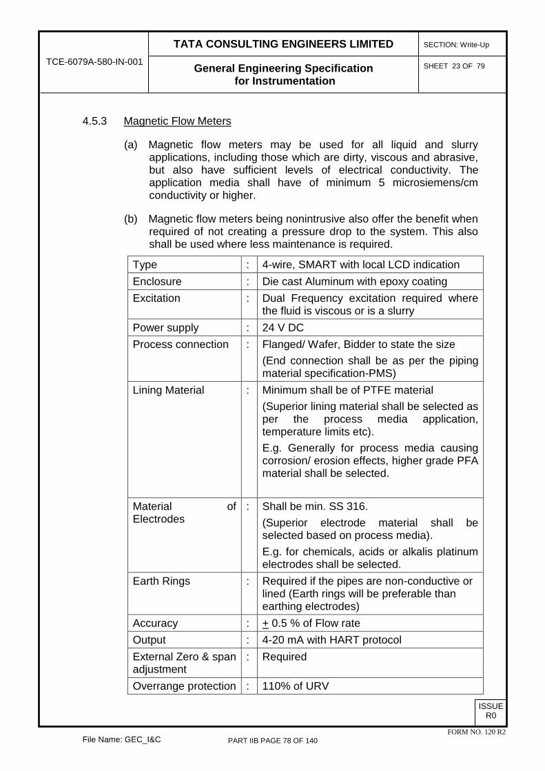
TATA CONSULTING ENGINEERS LIMITED
SECTION: Write-Up
TCE-6079A-580-IN-001 General Engineering Specification for Instrumentation
SHEET 23 OF 79
File Name: GEC_I&C
ISSUE R0
FORM NO. 120 R2
4.5.3 Magnetic Flow Meters
(a) Magnetic flow meters may be used for all liquid and slurry applications, including those which are dirty, viscous and abrasive, but also have sufficient levels of electrical conductivity. The application media shall have of minimum 5 microsiemens/cm conductivity or higher.
(b) Magnetic flow meters being nonintrusive also offer the benefit when required of not creating a pressure drop to the system. This also shall be used where less maintenance is required.
Type : 4-wire, SMART with local LCD indication Enclosure : Die cast Aluminum with epoxy coating Excitation : Dual Frequency excitation required where
the fluid is viscous or is a slurry Power supply : 24 V DC Process connection : Flanged/ Wafer, Bidder to state the size
(End connection shall be as per the piping material specification-PMS)
Lining Material : Minimum shall be of PTFE material (Superior lining material shall be selected as per the process media application, temperature limits etc). E.g. Generally for process media causing corrosion/ erosion effects, higher grade PFA material shall be selected.
Material of Electrodes
: Shall be min. SS 316. (Superior electrode material shall be selected based on process media). E.g. for chemicals, acids or alkalis platinum electrodes shall be selected.
Earth Rings : Required if the pipes are non-conductive or lined (Earth rings will be preferable than earthing electrodes)
Accuracy : + 0.5 % of Flow rate Output : 4-20 mA with HART protocol External Zero & span adjustment
: Required
Overrange protection : 110% of URV
PART IIB PAGE 78 OF 140

TATA CONSULTING ENGINEERS LIMITED
SECTION: Write-Up
TCE-6079A-580-IN-001 General Engineering Specification for Instrumentation
SHEET 24 OF 79
File Name: GEC_I&C
ISSUE R0
FORM NO. 120 R2
Cable entry : Shall be 1/2" NPT (F) Accessories : SS name plate
4.5.4 Rotameters
(a) These type instruments shall be used very selectively (shall be restricted to local measurements, utilities and purging only). Variable area flowmeters may be used where measurement with low accuracy is accepted.
(b) Accuracy of measurement shall be within +2% full scale. Rotameters shall be mounted in-line for pipe sizes upto 2 inches & for higher line sizes bypass rotameters shall be used. Rotameter rangeability shall be 10:1.
(c) Flow damper shall be provided for pulsating flow. Cooling fins shall be provided for high temperature service (150 deg C & above) & extension well shall be provided for low temperature service (0 deg C and below). Jacket shall be provided for crystallizing fluid at ambient temperature.
(d) Glass tube rotameters shall be used for low pressure utility services for local indication. Metal tube rotameter shall be used for process fluids.
4.5.5 Vortex Flowmeter
(a) Vortex meters shall generally be suitable for clean liquid, steam & gas flow measurement applications. This shall not be used for highly viscous applications i.e. Reynolds number shall be >10,000.
(b) This meter is preferred when higher accuracy together with high turndown ratio is required. This meter is preferred when less pressure drop is required.
(c) Vortex meters typically shall offer a turndown ratio of minimum 20:1 for liquids and minimum 15:1 for gases and steam. This meter shall be selected for pipelines sizes from ½” to maximum up to 12”.
(d) The overall accuracy shall be min. ± 1% of URV.
(e) The body material/ housing shall be of die-cast aluminum with epoxy/ polyurethane painting. All the wetted parts shall be minimum of SS 316. Superior material shall be selected as per the application requirement. Flange material shall also be of SS 316 minimum. The meter shall be provided with local LCD indication on
PART IIB PAGE 79 OF 140
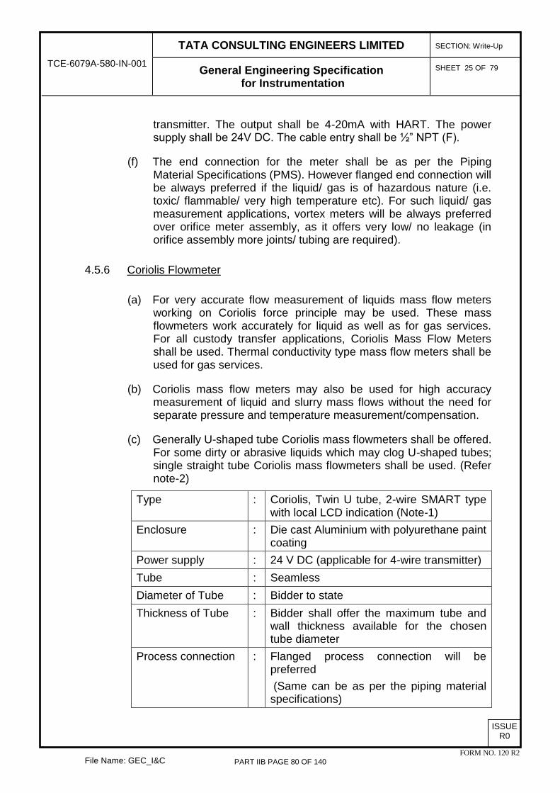
TATA CONSULTING ENGINEERS LIMITED
SECTION: Write-Up
TCE-6079A-580-IN-001 General Engineering Specification for Instrumentation
SHEET 25 OF 79
File Name: GEC_I&C
ISSUE R0
FORM NO. 120 R2
transmitter. The output shall be 4-20mA with HART. The power supply shall be 24V DC. The cable entry shall be ½” NPT (F).
(f) The end connection for the meter shall be as per the Piping Material Specifications (PMS). However flanged end connection will be always preferred if the liquid/ gas is of hazardous nature (i.e. toxic/ flammable/ very high temperature etc). For such liquid/ gas measurement applications, vortex meters will be always preferred over orifice meter assembly, as it offers very low/ no leakage (in orifice assembly more joints/ tubing are required).
4.5.6 Coriolis Flowmeter
(a) For very accurate flow measurement of liquids mass flow meters working on Coriolis force principle may be used. These mass flowmeters work accurately for liquid as well as for gas services. For all custody transfer applications, Coriolis Mass Flow Meters shall be used. Thermal conductivity type mass flow meters shall be used for gas services.
(b) Coriolis mass flow meters may also be used for high accuracy measurement of liquid and slurry mass flows without the need for separate pressure and temperature measurement/compensation.
(c) Generally U-shaped tube Coriolis mass flowmeters shall be offered. For some dirty or abrasive liquids which may clog U-shaped tubes; single straight tube Coriolis mass flowmeters shall be used. (Refer note-2)
Type : Coriolis, Twin U tube, 2-wire SMART type with local LCD indication (Note-1)
Enclosure : Die cast Aluminium with polyurethane paint coating
Power supply : 24 V DC (applicable for 4-wire transmitter) Tube : Seamless Diameter of Tube : Bidder to state Thickness of Tube : Bidder shall offer the maximum tube and
wall thickness available for the chosen tube diameter
Process connection : Flanged process connection will be preferred (Same can be as per the piping material specifications)
PART IIB PAGE 80 OF 140

TATA CONSULTING ENGINEERS LIMITED
SECTION: Write-Up
TCE-6079A-580-IN-001 General Engineering Specification for Instrumentation
SHEET 26 OF 79
File Name: GEC_I&C
ISSUE R0
FORM NO. 120 R2
Wetted Parts : SS 316 (Superior grade of material shall be selected as per the application media)
Sensor housing : SS 304 minimum Output : 4-20 mA with HART
(One output will be mass flow rate. Second output can be volume flow rate/ density/ temperature as per the application/ process requirements).
Liquid flow accuracy : Mass flow : ±0.1% of flow rate Volume flow: ±0.15% of flow rate Density: ±0.001g/cm3
Gas flow accuracy : Mass flow: ±0.50% of flow rate Cable entry : ½” NPT (F) Rangeability : 100:1 External Zero & span adjustment
: Required
Accessories : SS name plate
Notes
1. Integral mounted transmitter units shall be preferred; however remote mounted transmitters with integral cable shall be offered only when application demands (i.e. high temperature applications etc). In this case also transmitter will be mounted locally to the sensor maintaining as short as possible integral cable length.
2. Coriolis flowmeter sizing shall be done in such a way that; it shall be equal to the line size or minimum one size lesser than the line size to restrict the pressure drop to minimum.
4.5.7 Flow switches shall not be used.
4.5.8 Flow Glass
(a) Use of sight glass/ flow glass shall be restricted/ avoided as possible. When the application/ process media is hazardous (i.e. flammable/ toxic etc), use of sight glasses shall be strictly avoided.
(b) Sight glasses shall be used for local indication of flow (i.e. presence or absence of flow of the liquid/gas media without measurement). Single window/ double window type shall be selected as per the available visibility & accessibility. These types of sight glasses are suitable for color/ visible media. For transparent liquids or gases;
PART IIB PAGE 81 OF 140

TATA CONSULTING ENGINEERS LIMITED
SECTION: Write-Up
TCE-6079A-580-IN-001 General Engineering Specification for Instrumentation
SHEET 27 OF 79
File Name: GEC_I&C
ISSUE R0
FORM NO. 120 R2
the rotary/ paddle/ ball type of sight glasses shall be used.
Type : Shall be selected as per the application media
Material : Toughened borosilicate shatterproof glass. The body material shall be Carbon steel with SS316 wetted parts (Body shall be coated with epoxy or polyurethane paint)
Line size : Same as pipe size Accessories : SS Nameplate End connections : As per piping material specification(PMS) Applications : As required for local monitoring of flow in the
process.
4.6 Control Valves/ On-Off Valves
4.6.1 Type
(a) Control valves shall normally be globe type, top guided single seated type or eccentric disc rotary shaft type, except where high pressure drops, high capacity or other adverse conditions required for other type of valve.
(b) Butterfly valves may be used for control and on-off applications with size equal or larger than 8".
(c) Ball valves may be used for on-off applications.
(d) Other valve types like diaphragm valves (Saunders valve), rotary plug, angle or 3 way etc. shall be selected as per service requirements.
(e) Bonnet shall be provided with cooling fins or extension when the fluid temperature is 230oC and more and shall be of extension type for low temperature -18oC and below. For other services, standard bonnet shall be provided.
(f) Bellows seal shall be used where it is required to isolate the packing from the process fluid or where no leakage to atmosphere can be tolerated like toxic or flammable fluids.
(g) Control Valves upto 8” size & in steam service shall be provided with a manifold of block & bypass valves.
(h) All control valves shall be provided with ¾” drain valves in upstream & downstream sides. Drain valves shall be blind flanged.
PART IIB PAGE 82 OF 140
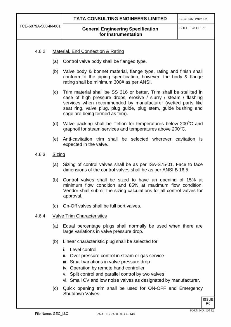
TATA CONSULTING ENGINEERS LIMITED
SECTION: Write-Up
TCE-6079A-580-IN-001 General Engineering Specification for Instrumentation
SHEET 28 OF 79
File Name: GEC_I&C
ISSUE R0
FORM NO. 120 R2
4.6.2 Material, End Connection & Rating
(a) Control valve body shall be flanged type.
(b) Valve body & bonnet material, flange type, rating and finish shall conform to the piping specification, however, the body & flange rating shall be minimum 300# as per ANSI.
(c) Trim material shall be SS 316 or better. Trim shall be stellited in case of high pressure drops, erosive / slurry / steam / flashing services when recommended by manufacturer (wetted parts like seat ring, valve plug, plug guide, plug stem, guide bushing and cage are being termed as trim).
(d) Valve packing shall be Teflon for temperatures below 200oC and graphoil for steam services and temperatures above 200oC.
(e) Anti-cavitation trim shall be selected wherever cavitation is expected in the valve.
4.6.3 Sizing
(a) Sizing of control valves shall be as per ISA-S75-01. Face to face dimensions of the control valves shall be as per ANSI B 16.5.
(b) Control valves shall be sized to have an opening of 15% at minimum flow condition and 85% at maximum flow condition. Vendor shall submit the sizing calculations for all control valves for approval.
(c) On-Off valves shall be full port valves.
4.6.4 Valve Trim Characteristics
(a) Equal percentage plugs shall normally be used when there are large variations in valve pressure drop.
(b) Linear characteristic plug shall be selected for
i. Level control ii. Over pressure control in steam or gas service iii. Small variations in valve pressure drop iv. Operation by remote hand controller v. Split control and parallel control by two valves vi. Small CV and low noise valves as designated by manufacturer.
(c) Quick opening trim shall be used for ON-OFF and Emergency Shutdown Valves.
PART IIB PAGE 83 OF 140

TATA CONSULTING ENGINEERS LIMITED
SECTION: Write-Up
TCE-6079A-580-IN-001 General Engineering Specification for Instrumentation
SHEET 29 OF 79
File Name: GEC_I&C
ISSUE R0
FORM NO. 120 R2
4.6.5 Valve Actuator
(a) Generally, control valve actuator shall be of the spring and diaphragm, pneumatically actuated type. Standard air control signal to positioner shall be 0.2 to 1.0 kg/cm2g. Piston type actuators with or without fail-safe capacity tanks shall be considered if actuator force requirements fall beyond the normal range of diaphragm actuators.
(b) For on-off valves, rotary/ piston actuators shall be provided as applicable. The actuators shall be spring return or double-acting type as per the fail-safe condition required. Local open/close indication shall be provided.
(c) All actuators shall be adequate to fully stroke the valve under the maximum differential pressure specified by the process requirements. They shall be sized for the shut off differential pressure.
(d) Valve actuators shall be sized for min. 4 kg/ cm2. (e) Control valve actuator shall be painted green for air fail-to-open
(FO) valves and red for air fail-to-close (FC) valves. (f) Electro-pneumatic valve positioners shall be provided for all control
valves. Air filter regulator filter to be 5 micron. Miniature type, plastic body & drain assembly etc .as parts of air filter regulator are not acceptable.
(g) E/P positioner shall be operating on input signal 4-20 mA DC. Proper canopy shall be provided for E/P positioners & other accessories as required.
(h) E/P Positioners, solenoid valves, booster relay, air lock relay, limit switches etc shall be supplied wherever required. All enclosures shall be metallic with epoxy painting.
(i) Separate air filter regulator shall be used for each E/P Positioner in case of control valves & solenoid valve in case of on-off valves.
(j) For control valves, hand wheel shall be considered where the block and by-pass valves are not provided in the process piping or when required by process. For on-off valves, hand wheel shall be provided. In general no by-pass or hand wheel shall be used for shutdown valves.
(k) Limit switches shall be of Proximity type. They shall meet NAMUR requirements when used in hazardous area. Limit switches shall be provided both for close and open positions for all on-off valves.
(l) Other auxiliary devices such as air lock relay, pilot relay, booster relay volume tank etc. shall be provided as parts of the actuating system in order to achieve the required stroke-speed, fail safe
PART IIB PAGE 84 OF 140

TATA CONSULTING ENGINEERS LIMITED
SECTION: Write-Up
TCE-6079A-580-IN-001 General Engineering Specification for Instrumentation
SHEET 30 OF 79
File Name: GEC_I&C
ISSUE R0
FORM NO. 120 R2
action etc.
4.6.6 Solenoid Valves
(a) Solenoid valves (Direct acting type) shall be used as the pilot valve for operation of On/Off valves.
(b) Solenoid valves, wherever used for on-off valves, shall be universal type three-way and be operated on 24 V DC, unless otherwise specified.
(c) The solenoid valves shall be continuous rated type with class H coil insulation as per IEC 85/IS 1271.
(d) Solenoid valves shall be in energized condition during normal operation. It shall have integral junction box with 1/2" NPT(F) cable entry. Flying leads are not acceptable. However, in case of a unit whose control shall be from existing control room, the existing control philosophy shall prevail and the solenoid valve operating voltage may be as required.
(e) Free wheeling diode shall be provided across the solenoid. (f) Solenoid valve body & trim shall be of SS316, as a minimum.
Positioners with inbuilt SOV are NOT acceptable. (g) The solenoid valves used in hazardous area shall be explosion
proof {Ex (d) type}.
4.6.7 Position Transmitters
Position transmitter shall be considered based on process requirements. Such transmitter shall be generally electronic, 2 wire type only.
4.6.8 Seat Leakage
(a) Seat leakage shall be chosen in accordance with process demands, safe operation of the plant and shall conform to ANSI / FCI 70.2. Seat leakage class for single ported and double ported valves or cage guided control valves shall be minimum class IV type. All tight shut-off valves shall meet Class V seat leakage class requirements for metal seated valves and Class VI requirements for soft seated valves as per FCI 70-2. All on-off valves shall meet Class VI seat leakage class.
(b) For control valves, Class-VI leakage class with soft seat shall be considered for fuel gas service to flare below 150 deg.C. and / or below 20 kg/cm2 pressure drop. Other than this metal to metal contact with leakage Class-IV shall be used for control valves.
(c) Soft seats shall be of Teflon (PTFE). (d) Shut-down valves shall be fire safe conforming to API 607. The
PART IIB PAGE 85 OF 140

TATA CONSULTING ENGINEERS LIMITED
SECTION: Write-Up
TCE-6079A-580-IN-001 General Engineering Specification for Instrumentation
SHEET 31 OF 79
File Name: GEC_I&C
ISSUE R0
FORM NO. 120 R2
complete valve assembly including the actuator, limit, switches, solenoid valve shall be fire safe.
4.6.9 Specific Requirements
(a) All control valves in service for temperature less than (-)20 deg.C, shall undergo cryogenic testing in line with BS-6364.
(b) All control valve castings in hydrogen service shall undergo helium leak test. Test reports shall be provided. Wherever NACE is applicable necessary certifications shall be provided.
4.6.10 Noise level measured at 1 metre downstream and 1 m upstream of pipe wall shall not exceed 85 dB. Source treatment of noise shall be by using special trims like anti-noise trims.
4.6.11 Self Actuating Regulators
Self actuating regulators shall be used where loads are constant & requirements of precision & accurate control are not stringent.
Type : Direct operated
Function : Pressure reduction
Body Type : Globe
Guiding : Top
Trim Form : Equal Percentage
Pressure Rating : Bidder to state
Leakage class : Class IV
Control Spring range : Bidder to state
Set Pressure : Shall be adjustable
Process Connection : Flanged, Bidder to state the Size & rating
Material of Construction (MOC)
a) Body/ Bonnet : As per PMS
b) Packing : Teflon
c) Trim : SS 316 min. Superior material shall be provided as required for process fluid being handled.
d) Seat : Soft (Teflon)
PART IIB PAGE 86 OF 140

TATA CONSULTING ENGINEERS LIMITED
SECTION: Write-Up
TCE-6079A-580-IN-001 General Engineering Specification for Instrumentation
SHEET 32 OF 79
File Name: GEC_I&C
ISSUE R0
FORM NO. 120 R2
g) Diaphragm : Nitrile Rubber
h) Spring : Carbon steel, Spring plating required
Accessories : SS Name Plate Notes: 1. Actuator to be sized for shut off differential pressure.
2. Positioners, actuators and accessories requiring tubing shall be mounted, valved and tubed.
3. Valve shall be sized to have an opening of 15% at min. And 85% at max flow conditions.
4.7 Analyzer
4.7.1 On-line gas analysers shall be provided as required. Analyzer system shall generally consist of several of the following items:
(a) Sample tap / probe (b) Sample pump & Sample transport system (piping to transport the
sample) (c) Sample conditioning system (filters, vaporizers, separators, etc) (d) Readout device (e) Analyser (f) Analyser cabinet / shelter (if required ) (g) Analyser shed
4.7.2 Liquid analysers such as pH, conductivity, silica shall be provided in DM plant.
4.7.3 Analyzer enclosure shall be weather proof to IP 65. The enclosure shall be explosion proof when installed in hazardous area, suitable for the hazardous area classification.
4.7.4 Analysers installed locally shall be protected by means of a shed, which shall protect the analyser from rainwater and direct sunlight.
4.7.5 The analyzer systems shall be supplied in fully assembled condition along with sample handling system and analyzer cabinets.
4.7.6 The principle of operation used shall be simple in design and shall avoid analytical complexity associated with development of information, which is extraneous to the application.
PART IIB PAGE 87 OF 140

TATA CONSULTING ENGINEERS LIMITED
SECTION: Write-Up
TCE-6079A-580-IN-001 General Engineering Specification for Instrumentation
SHEET 33 OF 79
File Name: GEC_I&C
ISSUE R0
FORM NO. 120 R2
4.7.7 The design used shall provide maximum reliability, maximum on-line performance and minimum maintenance. Instrument shall be field proven. No prototype instrument shall be offered.
4.7.8 Analyzer shall give isolated 4 to 20 mA output or as specified under the respective package specification.
4.8 Pressure Relief Valves
4.8.1 All pressure relieving devices shall be designed in accordance with ASME code for 'Boilers and Pressure Vessels', API-521 and Indian Boiler Regulations.
4.8.2 Pressure relief valves shall be full nozzle, full lift type except for thermal relief valves.
4.8.3 Conventional valves shall be specified for constant back pressure while bellows seal type valves shall be specified for variable back pressure more than 10% of set pressure. Pilot operated pressure relief valves shall be used for special services and where set pressure is closer than 10% of the operating pressure, in general.
4.8.4 Lifting lever shall be specified for steam and air service. Open bonnet shall be used for steam service. Where it is not acceptable for the media to escape, a packed lever shall be used.
4.8.5 3/4" x 1" threaded (NPT) modified nozzle type valves with typically 0.38 cm2 orifice size shall be specified for thermal relief.
4.8.6 The body material shall, as a minimum, be as per piping specifications. Nozzle and disc material shall be SS316 as a minimum with machined stainless steel guide and spindle.
4.8.7 The spring material of pressure relief valves shall be as follows unless otherwise necessary because of process conditions: - 29°C to 250°C : Cadmium/nickel plated carbon steel. above 250°C : Tungsten alloy steel. below - 29°C : Stainless steel 316
4.8.8 Flanged connection shall be for standard sizes 1" or larger.
4.8.9 Where permissible, screwed connections shall be used on sizes 3/4" and below.
4.8.10 Pressure relief valves in hydrocarbon vapour service shall normally be discharged to a flare system.
PART IIB PAGE 88 OF 140

TATA CONSULTING ENGINEERS LIMITED
SECTION: Write-Up
TCE-6079A-580-IN-001 General Engineering Specification for Instrumentation
SHEET 34 OF 79
File Name: GEC_I&C
ISSUE R0
FORM NO. 120 R2
4.8.11 All PSVs shall have 100% installed spares.
5.0 PROGRAMMABLE LOGIC CONTROLLERS (PLC)
5.1 PLC based control system shall be provided for monitoring and control of the package units, wherever applicable. The PLC shall be serving as data acquisition for display, process control and information. The PLC shall constitute central processing unit, input/ output modules for carrying out the functions of measurement and control systems.
5.2 Programmable Logic Controller (PLC)
5.2.1 The design material, construction features, manufacture, inspection and testing of Programmable Logic Controllers (PLC) shall comply with all currently applicable statutes, regulations and safety codes. The PLC shall comply with the latest applicable standards and codes. If any such standards are not applicable then the same shall comply with the available recommendations of professional institutes like NEMA, IEC, ANSI, ISA, IEEE, DIN and VDE.
5.2.2 Design and Construction Requirements
(a) PLC shall be provided as a stand-alone controller to perform combinational and sequential logic functions, flow totaliser, status monitoring and reporting functions. It shall carry out computation and interfacing for data acquisition, data storage and retrievals. It shall have different functional modules to perform the desired functions. It shall scan the inputs in time cycles and update the status of inputs/outputs.
(b) All cards shall be tropicalised.
(c) The PLC systems shall be expandable and shall be modular in construction so as to carry out the future expansion without any hardware modifications.
(d) All PLC shall use industrial and open standard protocols and structures for communication.
(e) The PLC system shall be capable of performing, as a minimum, the following functions:
i. Regulatory control functions. ii. Display of control loop status iii. Calculation of process related variables and parameters. iv. Auto / Manual Control
PART IIB PAGE 89 OF 140

TATA CONSULTING ENGINEERS LIMITED
SECTION: Write-Up
TCE-6079A-580-IN-001 General Engineering Specification for Instrumentation
SHEET 35 OF 79
File Name: GEC_I&C
ISSUE R0
FORM NO. 120 R2
v. Display of process variables. vi. Interlock, protection and sequence control functions. vii. Logging of alarms and events viii. System diagnostics. ix. Log/Report Generation.
(f) The PLC used shall have a proven record in the type of application concerned and in the prevailing environmental conditions.
(g) The system shall be highly reliable with high-integrity and high MTBF system. The total system availability shall be better than 99.99% as calculated from MTBF and MTTR of all the equipment/devices which are interconnected to form the system.
(h) On-line replacement of any module (communication modules, memory modules, power supply modules and I/O modules) shall be possible in such a way that the removal and addition of the module shall be possible without de-energizing the system. Further, there shall not be any interruption in the system while replacing a faulty module except for the inputs/outputs, which are being handled, by that module.
(i) Redundancy requirements shall be as defined in the respective package specifications.
(j) The design shall be such that in case of failure of the working module module, the changeover to the standby hardware shall be bumpless, without any disturbance to the running plant.
5.2.3 Central Processing Units
(a) The Central Processing Unit (CPU) shall be high performance processors with modular configuration suitable for real time process application. High inherent reliability, self-checking, error-recovery and trouble-shooting features shall be source of the features of CPU. The diagnostic messages from the controllers shall be stamped with date and time.
(b) The CPU shall be 32 bit minimum with floating point capability, suitable for real time process application.
(c) The controllers shall be provided with dual power supply modules.
PART IIB PAGE 90 OF 140

TATA CONSULTING ENGINEERS LIMITED
SECTION: Write-Up
TCE-6079A-580-IN-001 General Engineering Specification for Instrumentation
SHEET 36 OF 79
File Name: GEC_I&C
ISSUE R0
FORM NO. 120 R2
(d) LEDs shall be provided on the module to indicate the controller healthiness and operating modes such as RUN, STOP, MASTER mode.
(e) The controller shall have the facility to allow the operator to perform manual control of the controller output from a local Operator Interface Unit (OIU) mounted on the front facia of the control panel.
(f) In case of failure of processor, outputs shall automatically be driven to fail safe position which shall be user defined & shall be software configurable.
(g) In case of processor failure or power failure, the last state of pumps, drives & valves shall be maintained.
(h) The controller shall have a powerful instruction set which shall comprise of relay logic functions, timers, counters, sequencers, data manipulation instructions, comparison, code conversion, arithmetic instructions and function blocks.
(i) User program shall be protected from unauthorised access by software (password) protection.
(j) LEDs shall be provided on the module to indicate the controller healthiness and operating modes such as RUN, STOP, MASTER mode.
(k) The diagnostic messages from the controllers shall be stamped with date and time.
(l) It should be possible to mask the control strategies and/ or I/O points as and when required.
5.2.4 Communication Subsystem
(a) The system bus loading shall not exceed 60%. (b) Coaxial or fibre optic data bus shall be provided. (c) Communication interfaces required shall be as specified in the
respective package specifications.
5.2.5 Memory Unit
Memory with 2 years battery back-up shall be provided to store programs, standard software to perform logic functions, data acquisition and diagnostic features. Battery drain alarm/ indication shall be provided
PART IIB PAGE 91 OF 140

TATA CONSULTING ENGINEERS LIMITED
SECTION: Write-Up
TCE-6079A-580-IN-001 General Engineering Specification for Instrumentation
SHEET 37 OF 79
File Name: GEC_I&C
ISSUE R0
FORM NO. 120 R2
on the OIU. 40% spare memory shall be provided. The application & system software shall reside in non-volatile memory.
Memory modules as required to store the programs & standard software for performing logic functions & diagnostic functions shall be provided. Main memory shall be modular and facility shall be provided for upgradation and expansion of memory to meet future demands.
5.2.6 Input / Output Modules
(a) Standard rack mounted I/O modules with plug-in cards shall be provided.
(b) Some of the common features of the I/O modules shall be as follows:
i. Each digital I/O shall be optoisolated.
ii. Each analog I/O shall be galvanically isolated.
iii. Filters shall be provided for noise rejection
iv. Input /output status shall be indicated by an LED.
v. The minimum isolation level between I/O and logic circuit shall be 500 VDC.
vi. Each I/O shall be protected against reversal of polarity of the input voltage to I/O and over voltage protection upto twice the rated voltage.
vii. Each module shall have LED for each I/O channel to indicate the status of each input/output.
viii. All inputs shall be double ended i.e. two wires per input and not common return for all inputs.
ix. Potential free relay outputs shall be provided for operating any motors, valves etc. Wet contacts/powered contacts/TTL contacts etc. shall not be acceptable.
x. Relay boards with plug-in type relays shall be provided for interposing.
xi. In case of system failure or power supply failure all the outputs shall attain pre-determined fail safe condition.
xii. In case any input/ output module fails during operation, the PLC shall not stop and shall keep functioning without the faulty module.
PART IIB PAGE 92 OF 140

TATA CONSULTING ENGINEERS LIMITED
SECTION: Write-Up
TCE-6079A-580-IN-001 General Engineering Specification for Instrumentation
SHEET 38 OF 79
File Name: GEC_I&C
ISSUE R0
FORM NO. 120 R2
xiii. The I/O modules shall have diagnostic features i.e., in case of failure of any I/O channel an alarm "PLC trouble" shall be generated automatically.
xiv. For motors, MCC feedback to the PLC shall be considered for on & trip. Off status shall be considered as negation of on status in the PLC. Single output shall be provided for start & stop commands.
xv. Single digital output shall be provided for open & close commands for valves. Limit switches for open & close status of the valves shall be separately wired to the PLC.
5.2.7 Spare Philosophy
The system shall have the following minimum spare capability, unless otherwise mentioned in the package specifications:
(a) 10% wired spares for each type of I/Os subject to min. of one module in each type (after commissioning).
(b) Minimum 10% spare wired slots shall be made available in each chassis for future expansion. These slots shall be the part of the offer.
(c) Controller loading shall not exceed 60%. The same shall be proven by calculations submitted alongwith offer and also demonstrated during FAT & Site Acceptance Tests.
(d) Whenever relays are used (if applicable) to interface process input/outputs with PLC, 10% additional relays shall be provided. In addition, 10% spare space shall be provided in panels/junction box / cabinets to install 10% additional relays or other items in future.
5.2.8 PLC Software
(a) PLC programming shall be carried using latest available industrial standard formats for logic. The PLC code shall be structured in the manner of the best industry standard and have comprehensive subroutine and rung annotation.
(b) User program shall be protected from unauthorised access by software (password) protection.
(c) The application programmes shall be additionally provided on DVDs.
PART IIB PAGE 93 OF 140

TATA CONSULTING ENGINEERS LIMITED
SECTION: Write-Up
TCE-6079A-580-IN-001 General Engineering Specification for Instrumentation
SHEET 39 OF 79
File Name: GEC_I&C
ISSUE R0
FORM NO. 120 R2
(d) The controller programming shall be from Purchaser‟s laptop. Dedicated serial communication port shall be provided on the controller for initial set-up configuration/diagnostic through the COM port of laptop.
(e) Purchaser‟s Laptop shall serve as the programming unit for the PLCs. It shall be possible to make on-line programming changes in the CPU of the PLCs using Laptop. 1 No. licensed copy of the engineering software (programming & documentation software) shall be loaded on Purchaser‟s Laptop for performing the same. The software loaded in the Laptop shall have facilities for the following: (i) Carrying out program revision management (ii) Insertion of comprehensive program subroutine and rung
comments (iii) Search and find and search and replace „contacts‟ and „coils‟ (iv) Simulation functions and testing of the program by changing
the status of contacts and monitoring the outputs (v) Preparation of coil and contact list and their locations and
memory maps. (vi) Make system backup copies while the system is online. (vii) Upload and down load programs to the PLC online. (viii) Carry out line maintenance and fault finding on the PLC.
5.2.9 The system shall have an extensive set of self-diagnostic routines which shall be able to identify the system failures at least upto module level including redundant components and power supplies.
5.2.10 System Availability
The total system availability shall be better than 99.99% as calculated from MTBF and MTTR of all the equipment/devices which are interconnected to form the system. Components used in the equipment and system shall be designed with higher rating than required to have higher availability of the system.
5.2.11 Alarms and Annunciation
The following faults shall be indicated by LED in individual module: (a) Power supply failure. (b) Individual card failure. (c) Controller fault.
PART IIB PAGE 94 OF 140

TATA CONSULTING ENGINEERS LIMITED
SECTION: Write-Up
TCE-6079A-580-IN-001 General Engineering Specification for Instrumentation
SHEET 40 OF 79
File Name: GEC_I&C
ISSUE R0
FORM NO. 120 R2
(d) Battery fault.
5.2.12 Operator Interface Unit (OIU)
The OIU shall have alphanumeric LCD colour display. Membrane type function keys shall be provided. It shall provide following facilities for the operator: (a) All set points, control parameters, alarm limits and timers (i.e. time
settings for all the operation cycles) shall be adjustable through the Operator Interface Unit (OIU) with suitable password protection.
(b) Display the plant layouts in a graphical format with instrument details (static & dynamic) and details of motors (i.e. running, stopped, fault etc.) & valves (open/close).
(c) Provide „System Start‟/ „Cycle Start‟ commands for initiating automatic sequential operation of a system in auto mode.
(d) Manual operation of various motors/drives & valves in the plant. (e) Archive data records (f) Provide facilities for the operator to:
(i) Manipulate control loops including changing set point, output, configuration, tuning and computational constants;
(ii) Select process modes (Auto/ Menu driven/ Manual);
(iii) Acknowledge alarms, reset & test;
(iv) View a journal of acknowledged & unacknowledged alarms
(g) Display analog and digital process variables of control loops, open loops and all other loop related parameters on the appropriate graphic screen (displays shall change colour on fault conditions or when data is suspected).
(h) Display process set points (i) Logging and trending including historical trend recording. (j) Self diagnostic messages (k) Generate reports & logs. (l) Security systems shall be provided to prevent unauthorised
adjustment of process set points or give commands for operation in auto, menu driven & manual modes.
(m) Provide data archiving facilities through Laptop computer. (n) Graphic screens shall be provided as follows :
i. Main and subsystem menus
PART IIB PAGE 95 OF 140

TATA CONSULTING ENGINEERS LIMITED
SECTION: Write-Up
TCE-6079A-580-IN-001 General Engineering Specification for Instrumentation
SHEET 41 OF 79
File Name: GEC_I&C
ISSUE R0
FORM NO. 120 R2
ii. Plant overview iii. Overview of control system iv. Screens for viewing status of each plant area v. Alarm and event schedules vi. Screens to permit viewing and modifying of process set points.
(o) The system shall have the capacity of having and developing graphic symbol library as per ISA 5.1 and 5.3.
(p) Any change made in any parameter for an input from any display shall be automatically updated on all displays configured for that input.
(q) Annunciate alarms including details of the time the alarm occurred and when it returned to normal. It shall give alarm log giving individual status. All the alarms shall be displayed on OIU with Hooter sound generation.
Sl. No.
Description Bidder to state/ confirm
1.0 GENERAL 1.1 Manufacturer : Bidder to State 1.2 Model no. : Bidder to State 1.3 Proven track record : BIDDER shall design the system
such that the system is capable of performing the operations it is intended for as per this specification. Bidder shall provide a field proven system. The offered hardware & software shall have a proven track record of minimum 1 installation in the Indian market which is functioning satisfactorily for the past 1 year minimum.
1.4 Criteria for proven track record
: Same controller
1.5 System power supply : 110 VAC from UPS 1.6 Card replacement with
power on for systems : Required
1.7 Configuration diagram : Bidder to enclose the configuration diagram for the
PART IIB PAGE 96 OF 140

TATA CONSULTING ENGINEERS LIMITED
SECTION: Write-Up
TCE-6079A-580-IN-001 General Engineering Specification for Instrumentation
SHEET 42 OF 79
File Name: GEC_I&C
ISSUE R0
FORM NO. 120 R2
Sl. No.
Description Bidder to state/ confirm
system offered. 1.8 Posting of hardware and
software engineers during erection, commissioning & final acceptance test
: 1. During warranty period, the maintenance call must be attended within 24 hours. The plan from the bidder must be submitted to support this requirement.
2. Contractor‟s engineer shall be made available for assistance in operation, maintenance, tuning & training of Purchaser‟s personnel at Site during & after commissioning of system. Bidder shall indicate in his offer the duration of posting of his engineers at site.
3. Training of Purchaser‟s personnel on both hardware & software development. Bidder to indicate the duration of training & no. of Purchaser‟s personnel accommodated in the training.
2.0 CONTROLLER 2.1 Microprocessor based : Yes 2.2 Configurable multi loop
controller : Required, PLC shall be capable
of running multiple loops of different scan times with assigned priority. The scan times shall be selectable
2.3 Redundancy Requirements : As specified in the respective Package specifications
2.4 Status monitoring of power supply modules of CPU & I/O modules
: Required
2.5 Model no. : Bidder to state
PART IIB PAGE 97 OF 140

TATA CONSULTING ENGINEERS LIMITED
SECTION: Write-Up
TCE-6079A-580-IN-001 General Engineering Specification for Instrumentation
SHEET 43 OF 79
File Name: GEC_I&C
ISSUE R0
FORM NO. 120 R2
Sl. No.
Description Bidder to state/ confirm
2.6 Processor and word length : 32 bit 2.7 Changeover time from main
to standby controller (in case of redundant controllers)
: Shall be bumpless. Both controllers shall be active at all times.
2.8 Logic changes possible through laptop
: Yes, with necessary security. Both on-line & offline modification will be possible.
2.9 Self-diagnostics software required
: In the processor
2.10 Online configuration possibility
: Required
2.11 Logic changes in main controller down load to redundant controller automatically
: Required in case of redundant controllers
2.12 Output status on loss of power
: Outputs shall go to fail safe position
2.13 User memory : Bidder to State 2.14 Battery type : Ni-Cd with min. 2 years lifetime 2.15 Battery drain alarm/
indication : Required, on OIU
2.16 Interfaces and communication ports for each controller
: (a) Communication port for interfacing with Purchaser‟s
laptop based programming unit.
(b) Other communication ports required as specified in the respective package specifications
2.17 Redundant communication : (a) Between main & redundant controllers (in case of redundant system)
(b) Between controller & I/O modules
PART IIB PAGE 98 OF 140

TATA CONSULTING ENGINEERS LIMITED
SECTION: Write-Up
TCE-6079A-580-IN-001 General Engineering Specification for Instrumentation
SHEET 44 OF 79
File Name: GEC_I&C
ISSUE R0
FORM NO. 120 R2
Sl. No.
Description Bidder to state/ confirm
2.18 Galvanic isolation for input/output & power supply
: Required
2.19 CPU, Memory & Bus loading
: Shall not exceed 60%. The same shall be demonstrated at site during Site Acceptance Tests.
2.20 Features of Data Acquisition & Control System Software
2.20.1 Sequence control functions : Required 2.20.2 Control modes : Auto, Menu driven, Discrete 2.20.3 Real Time Trending function
& Historical Trending : Required
2.20.4 Logging functions 2.20.5 Alarm display function 2.20.6 Group display function : Required 2.20.7 Alarm handling function : Required
3.0 INPUT/OUTPUT SYSTEM 3.1 Signal isolation for all I/Os : Optical or galvanic 3.2 Individual fuse for each
Digital input & output : Required, Fused Terminals shall
be provided.
3.3 Module failure indication in module and PLC
: Required
3.4 Analog input module 3.4.1 Model No. : Bidder to State 3.4.2 No. of points/module : Bidder to State 3.4.3 Type of inputs : 4-20 mA, 2 wire inputs for 2-wire
transmitters
3.4.4 Accuracy : Bidder to State 3.4.5 HART protocol support : Not Required 3.4.6 Type of isolation : Galvanic 3.5 Analog output module 3.5.1 Model No. : Bidder to State
PART IIB PAGE 99 OF 140

TATA CONSULTING ENGINEERS LIMITED
SECTION: Write-Up
TCE-6079A-580-IN-001 General Engineering Specification for Instrumentation
SHEET 45 OF 79
File Name: GEC_I&C
ISSUE R0
FORM NO. 120 R2
Sl. No.
Description Bidder to state/ confirm
3.5.2 No. of points per module : Bidder to State 3.5.3 Type of outputs : 4-20 mA 3.5.4 Accuracy : Bidder to State 3.5.5 Type of isolation : Galvanic 3.6 Digital input module 3.6.1 Model No. : Bidder to State 3.6.2 No. of inputs / module : Bidder to State 3.6.3 Type of input : Potential free contacts 3.6.4 Type of isolation : Optical 3.7 Digital output module 3.7.1 Model No. : Bidder to State 3.7.2 No. of outputs per module : Bidder to State 3.7.3 Type of outputs : Potential free output of suitable
rating
3.7.4 Output Status : Outputs shall change to fail-safe position in case processor failure or module failure.
3.7.5 I/O Summary Bidder to furnish during detailed engineering
4.0 APPLICATION PROGRAMME
: To be provided in R/W DVDs (2 Nos.)
5.0 ENGINEERING SOFTWARE
1 No. licensed copy to be loaded in Purchaser‟s laptop.
6.0 JUNCTION BOXES
6.1 Separate Junction boxes shall be provided for the following types of signals:
(a) Analogue Input/ Analogue Output (b) Digital Input (c) Digital Output. Separate junction boxes shall be provided for AC &
DC interrogation voltages. (d) Power Supply (e) Thermocouples
PART IIB PAGE 100 OF 140

TATA CONSULTING ENGINEERS LIMITED
SECTION: Write-Up
TCE-6079A-580-IN-001 General Engineering Specification for Instrumentation
SHEET 46 OF 79
File Name: GEC_I&C
ISSUE R0
FORM NO. 120 R2
(f) Gas Detectors (g) Vibration Signals, if any.
6.2 Separate junction boxes shall be used for IS & non-IS signals. 6.3 The weather protection class for all junction boxes mounted outdoor
shall be IP-65 and for those mounted indoors shall be IP-52. 6.4 Material of construction shall be as below:
(a) Safe area – Cast Aluminium LM-6 body (b) Hazardous area
i. Cast Aluminium LM-6 body, ex-proof with Ex(d) certification. These junction boxes shall be CCOE approved for the specified hazardous area class.
ii. Junction boxes to which intrinsically safe signals are wired shall be same as those for the safe area, except that they shall be blue in clour.
6.5 The junction boxes shall have terminals suitable for minimum of 2.5 mm2 cable. 20% spare terminals shall be provided in each junction box.
6.6 Each junction box shall have a minimum of 20% or 2 Nos. minimum spare entries. All spare entries shall be provided with SS plugs. Branch cable entries shall be from the sides and cable entries for multipair/ multicore cables shall be from the bottom.
6.7 Junction box colours shall be as below: (a) For Intrinsically safe signals/ Gas detector signals – Blue (b) Thermocouple signals – Yellow (c) Others – Black
6.8 A screwed, laminated plastic nameplate with the junction box number shall be provided on the cover plate.
6.9 Separate shield bus shall be provided.
7.0 CONTROL PANELS
7.1 All control panels shall be supplied in pre-wired condition and shall be checked at manufacturer‟s works prior to despatch.
7.2 Protection Class
7.2.1 The IP protection for all panels shall comply with the requirements of protection classes as indicated below.
In-door Air-conditioned (A.C.) areas IP 20 In-door Non A.C. areas IP 52
PART IIB PAGE 101 OF 140

TATA CONSULTING ENGINEERS LIMITED
SECTION: Write-Up
TCE-6079A-580-IN-001 General Engineering Specification for Instrumentation
SHEET 47 OF 79
File Name: GEC_I&C
ISSUE R0
FORM NO. 120 R2
Outdoor areas IP 65
7.2.2 For Local Panels installed in hazardous areas, the panel enclosure shall be ex-proof or pressurized panel with purge system as per NFPA 496 depending upon the size of the panel and other design criteria in the hazardous areas or as defined in the respective package specifications. In case of pressurized panels, an alarm shall be provided on the Local Panel and a contact shall be provided for remote annunciation, whenever the panel pressurisation falls below a minimum pressure value.
7.2.3 Panel pressurisation with start-up panel purging scheme shall be fully automatic. However, it shall be started manually from a pushbutton. Solenoid valves & differential pressure switch required for panel purging shall be ex-proof.
7.2.4 For ex-proof panels, all items mounted on the front facia such indicating lamps, pushbuttons, alarm annunciators shall be ex-proof. If the panel is purged, potential free contacts from the hazardous area shall be wired to indicating lamps, alarm annunciator through IS isolators (active safety barriers) mounted inside the panel. Intrinsically safe alarm annunciators can also be used in purged panels.
7.3 Type, Material & Construction
7.3.1 Ex-proof panels shall be of Cast Aluminium LM6 alloy. Latest certificate from CCOE is mandatory for all explosion protected and IS equipment / components. Also for sections of the panels which are fully explosion protected / IS equipment CMRI/ ATEX certificates & CCOE certificate shall be provided.
7.3.2 For other panels, panel fabrication shall be in best workmanship manner with cold rolled steel sheets. The panels shall be rigid self supporting structure and fabricated preferably from min 2 mm thick cold rolled sheet. Doors & gland plates shall be of 3 mm thickness. Each panel shall be provided with lifting eye bolts of removable type. Panel shall have lockable door handles, with lock and key.
7.3.3 Steel sheets for panels, operator interface units and accessories mounted shall be cut on a squaring shear to ensure tight flush joint when butted together. Stiffeners shall be provided wherever required to prevent buckling and to have a smooth surface finish.
7.3.4 Bolts or screws shall not be exposed on the face of the panel. Welded coupling of panel sections is not allowed. Adjacent panels shall be assembled with face flush. Gaps or cracks shall not be visible from the front of assembled panels.
PART IIB PAGE 102 OF 140

TATA CONSULTING ENGINEERS LIMITED
SECTION: Write-Up
TCE-6079A-580-IN-001 General Engineering Specification for Instrumentation
SHEET 48 OF 79
File Name: GEC_I&C
ISSUE R0
FORM NO. 120 R2
7.3.5 Framework shall be from 50 x 50 x 6thick MS angle min..
7.3.6 All exposed surface in plain view shall be perfectly level, smooth and free from any protrusions and tool or clamp marks. All edges including cut outs shall be ground smooth.
7.3.7 Cutouts for mounting of instruments, displays, push buttons etc. shall be made by machine saw/hack saw/drilling. Gas cutting of cutouts is not acceptable. Sharp corners left after cutting operation shall be rounded off to a smooth finish. Spare/Future Instrument Cutouts shall be properly closed with Dummy Plates from Rear End.
7.3.8 Each section shall have provision for cables entry by means of removable seal tight gland plates for all power/ control/ signal cables. Tapped holes shall be provided in the frame work to fix the cables to the plate.
7.3.9 Fasteners used in fabrication shall be of Stainless steel. All hinges, screws other non painting parts shall be of stainless steel material.
7.3.10 Lamps shall be fixed to the back plate in such a way as to facilitate easy removal of LEDs. All indicating lamps shall be cluster LED type.
7.3.11 For all rack/surface mounted instruments mounted at the rear of panel, supply of mounting screws, nuts, etc.; are included in the panel vendor's scope even though the mounting of these instruments may or may not be included in the vendor's scope.
7.3.12 Panels and accessories shall be designed and fabricated in accordance with the specifications and in accordance with latest instrumentation code of practices.
7.3.13 All the electrical components and accessories shall be in accordance to meet the requirements of area classifications.
7.4 Dimensions
7.4.1 Panel doors shall cover the total width and height of a panel section. All doors shall have continuous stainless steel plane hinges in case of panel fabricated out of sheet steel. Panels of 800/1200mm wide shall have double front & rear doors.
7.4.2 Mounting channel frame shall be made from ISMC 100 channel (100 x 50 x 6 mm). Maximum dimensions shall be 2100 mm (H) x 1200 mm (W) x 1000 mm (D), including height of base channel of 100 mm. Vendor shall indicate the dimensions of the panel offered.
PART IIB PAGE 103 OF 140
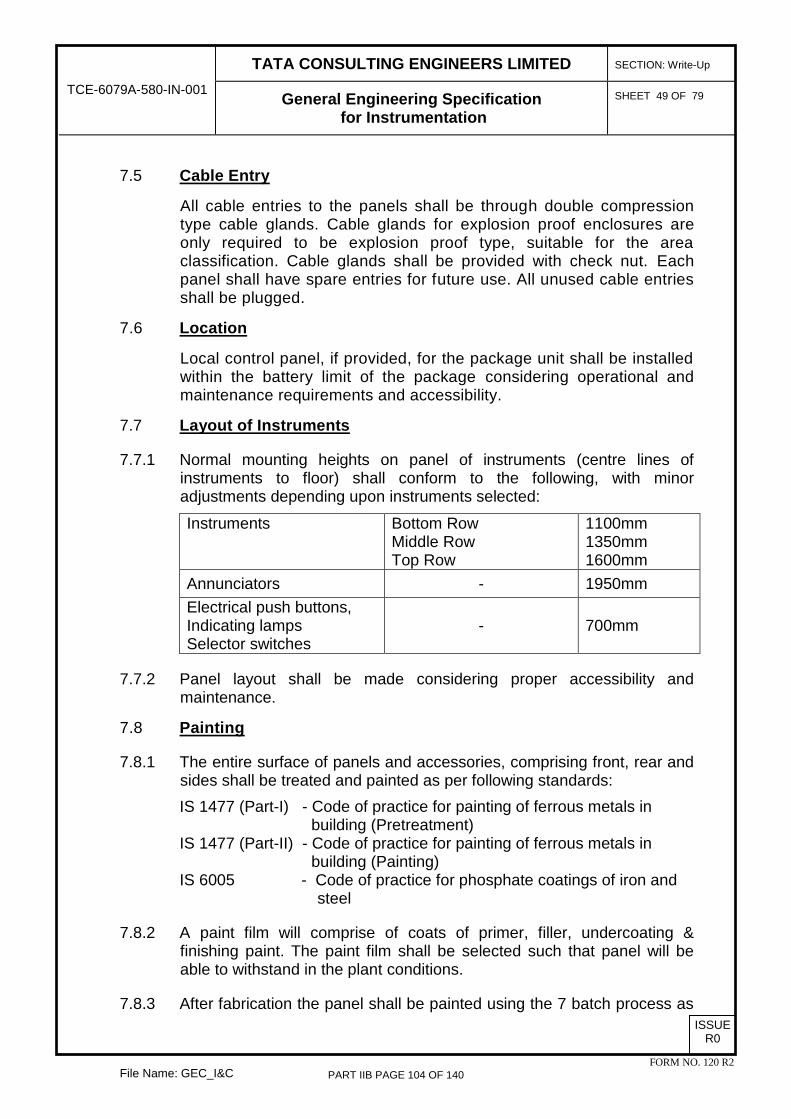
TATA CONSULTING ENGINEERS LIMITED
SECTION: Write-Up
TCE-6079A-580-IN-001 General Engineering Specification for Instrumentation
SHEET 49 OF 79
File Name: GEC_I&C
ISSUE R0
FORM NO. 120 R2
7.5 Cable Entry
All cable entries to the panels shall be through double compression type cable glands. Cable glands for explosion proof enclosures are only required to be explosion proof type, suitable for the area classification. Cable glands shall be provided with check nut. Each panel shall have spare entries for future use. All unused cable entries shall be plugged.
7.6 Location
Local control panel, if provided, for the package unit shall be installed within the battery limit of the package considering operational and maintenance requirements and accessibility.
7.7 Layout of Instruments
7.7.1 Normal mounting heights on panel of instruments (centre lines of instruments to floor) shall conform to the following, with minor adjustments depending upon instruments selected:
Instruments Bottom Row Middle Row Top Row
1100mm 1350mm 1600mm
Annunciators - 1950mm Electrical push buttons, Indicating lamps Selector switches
- 700mm
7.7.2 Panel layout shall be made considering proper accessibility and maintenance.
7.8 Painting
7.8.1 The entire surface of panels and accessories, comprising front, rear and sides shall be treated and painted as per following standards: IS 1477 (Part-I) - Code of practice for painting of ferrous metals in
building (Pretreatment) IS 1477 (Part-II) - Code of practice for painting of ferrous metals in
building (Painting) IS 6005 - Code of practice for phosphate coatings of iron and
steel
7.8.2 A paint film will comprise of coats of primer, filler, undercoating & finishing paint. The paint film shall be selected such that panel will be able to withstand in the plant conditions.
7.8.3 After fabrication the panel shall be painted using the 7 batch process as
PART IIB PAGE 104 OF 140

TATA CONSULTING ENGINEERS LIMITED
SECTION: Write-Up
TCE-6079A-580-IN-001 General Engineering Specification for Instrumentation
SHEET 50 OF 79
File Name: GEC_I&C
ISSUE R0
FORM NO. 120 R2
follows:
(a) Acid cleaning followed by washing with water. (b) Alkali cleaning followed by washing with water. (c) Phosphating and water cleaning. (d) Application of first coat of epoxy primer followed by oven baking. (e) Wet sanding, application of putty to level any imperfections. (f) Application of second coat of epoxy primer followed by oven
baking. (g) Application of first coat of final epoxy paint followed by oven baking, (h) Final application of putty to level out any remaining imperfections. (i) Application of second coat of epoxy paint followed by oven baking.
7.8.4 A final coat of finish paint of high grade lacquer enamel shall be given after assembly and filling of front panel butt joints with suitable filler, to present a continuous panel surface.
7.8.5 The finish of the final coat shall be of semi-gloss texture to minimise light reflection.
7.8.6 Unless otherwise specified, exterior portion of all panels and closed cabinets shall have a colour of light gray shade RAL -7035 as per IS 5. The finish of the final coat shall be of semi-gloss texture to minimise light reflection. Channel base shall be of black colour.
7.9 All lamps, status as well as alarm, shall be provided with lamp test facility. One single lamp test push button shall be used for each panel.
7.10 Blowers & louvers with SS mesh & filter shall be provided in each safe area panel wherever the panel is located indoors. Power supply for all blowers, wherever provided, shall be provided through MCBs.
7.11 For panel interior lighting, CFL lamps with operating door switch and protective devices like MCBs shall be provided for every section of closed panels/ cabinets.
7.12 A 5/15 Amp 230V, 1 phase, 50 Hz, AC 3 pin plug point shall be provided in the interior of each panel with ON/OFF control switch and MCB. This is for panels located in safe area.
7.13 Anti-vibration pads (15 mm thickness) shall be provided for free standing panels.
PART IIB PAGE 105 OF 140

TATA CONSULTING ENGINEERS LIMITED
SECTION: Write-Up
TCE-6079A-580-IN-001 General Engineering Specification for Instrumentation
SHEET 51 OF 79
File Name: GEC_I&C
ISSUE R0
FORM NO. 120 R2
7.13.1 The design of panel shall incorporate and provide for adequate spare capacity for future expansion. Each panel shall be provided with following additional equipment as a minimum:
(a) 10% of panel mounted instruments inside / front of panel including lamps push buttons, switches, relays, barriers etc.
(b) 10% spare terminals
(c) 10% additional power feeders each provided with switch fuse assembly
(d) 20% additional spare windows in alarm annunciator
(e) 10% spare cable entry points (of each type)
8.0 PANEL/JUNCTION BOX WIRING & ACCESSORIES
8.1 Wiring
8.1.1 All inter cubical and internal wiring for all panels/ junction boxes/power distribution boards shall be carried out with 1100V grade, stranded tinned copper conductors. Cross section of conductors shall be as specified earlier in this section. Control & Power wiring shall be segregated and routed in PVC troughs. The PVC troughs shall not be more than 70% full. Different colour wires shall be used for different voltages.
8.1.2 All wiring shall be done with straight & cross ferruling. Ferrules shall be printed type. Ferrule material shall be silicone type. Ferruling for core/wire identification shall be done using corresponding with the panel diagram & shall be fitted at both ends of each wire.
8.1.3 Large cross section cables shall be terminated on short bus bars with insulating barriers and acrylic shroud for protection, in case suitable size terminals are not available.
8.1.4 Bus bars wherever used shall be of electrolytic copper with nickel/chromium plating. Tapped holes with nickel/chromium plated screws shall be used for cable terminations. Bus bars with through holes and bolt/nut arrangement shall be avoided as much as possible. Bus bars shall be suitably covered with transparent acrylic sheets. All live parts shall be properly shielded by use of acrylic shrouds.
8.1.5 Vendor will be provided power supply as specified in the package specifications. It is the vendor‟s responsibility to do the internal distributions as per the requirement. Vendor also shall consider a
PART IIB PAGE 106 OF 140

TATA CONSULTING ENGINEERS LIMITED
SECTION: Write-Up
TCE-6079A-580-IN-001 General Engineering Specification for Instrumentation
SHEET 52 OF 79
File Name: GEC_I&C
ISSUE R0
FORM NO. 120 R2
suitable power pack in redundant configuration in the scope of supply for the power to internal panel components.
8.1.6 Intrinsically safe (IS) wiring shall be routed in separate race ways, separate from non- intrinsically safe (Non-IS) and power wiring wherever applicable. Colour code for IS cables, terminals and its race ways shall be blue in colour. Vendor shall run the cables of different voltage levels in separate raceway as IS and non IS cables. Intrinsically safe wiring & terminals shall be light blue in colour and shall be separated from non-intrinsically safe terminals.
8.1.7 Wires carrying measurement signals associated with resistance thermometers and other low level signals shall be routed in separate wire ways and not along with power cables. Power wiring and control wiring shall be separated by not less than 150 mm. Philosophy of segregating of raceways carrying intrinsic and non intrinsic cables and power cables shall be followed throughout.
8.1.8 All wiring external to main panel / cubicles (except for alarm annunciator) shall be terminated in terminal strips and their quantity and size shall be determined by the vendor. Wiring between cubicles or panel sections shall be terminated in terminal blocks at each end.
8.1.9 Rubber/plastic grommets shall be used for wire entry into individual instrument cases and for entry/ exit of cables through raceways.
8.1.10 Wire coding shall be as below: (a) Signals
Negative – Black Positive – White
(b) Triple Signals Negative – Black Positive – White Signal – Blue
(c) DC Power
Negative – Black Positive – Red
(d) Earthing Safety Earth – Green with yellow tracer Instrument Earth – Green
PART IIB PAGE 107 OF 140

TATA CONSULTING ENGINEERS LIMITED
SECTION: Write-Up
TCE-6079A-580-IN-001 General Engineering Specification for Instrumentation
SHEET 53 OF 79
File Name: GEC_I&C
ISSUE R0
FORM NO. 120 R2
8.2 Cable Terminations
8.2.1 All necessary cable terminating accessories such as removable gland plates, compression glands, supporting clamps and brackets, wiring troughs etc. shall be included in the Contractor‟s scope of supply.
8.2.2 Terminal blocks shall be 660V grade, 20 amps rated, one-piece moulded, complete with screw type terminals, mounted on C channel and clip on type. All terminal strips shall be mounted on suitable anodized metallic or plastic stand off. Terminal strips shall be arranged group wise for incoming and outgoing cables separately.
8.2.3 All terminals shall be of mechanical screw clamp type. Terminals shall be suitable to accept 2.5mm² size conductor for control and signal cable, as a minimum. Terminal blocks for different voltages or circuit type shall be segregated into groups and distinctively labelled.
8.2.4 Termination shall be done using crimp type lugs. One terminal shall be used for terminating one wire only. Terminals shall be Phoenix or Wago type. Shorting shall be achieved through standard shorting links available.
8.2.5 Separate set of terminals for power cables shall be provided with 4.0mm² size.
8.2.6 Markings on the terminal strips shall correspond to wire numbers on the wiring diagrams. Every terminal shall be uniquely identified within the terminal cabinet by means of a terminal number. Crimped terminations shall be applied to all cable ends to ensure sound termination to terminal blocks and all circuit components. No tees or joints between termination points shall be permitted. All spare contacts and terminals of the panel mounted equipment and devices shall be wired to terminal blocks.
8.2.7 For PLC/DCS panels, fused isolating switches with visual indication of fuse down shall be provided at each digital input & output terminal. For all other inputs/outputs, knife type isolating switches shall be provided to isolate field input and output for maintenance purpose.
8.3 Relays
All relays used for interposing shall have at least 2 nos. changeover contacts. The relays shall have status indication and shall be provided with free wheeling diodes.
8.4 Labels
All front mounted equipment, as well as equipment mounted inside the junction boxes, consoles, panels, power distribution boards shall be
PART IIB PAGE 108 OF 140

TATA CONSULTING ENGINEERS LIMITED
SECTION: Write-Up
TCE-6079A-580-IN-001 General Engineering Specification for Instrumentation
SHEET 54 OF 79
File Name: GEC_I&C
ISSUE R0
FORM NO. 120 R2
provided with individual labels with equipment designation engraved. These shall be laminated Perspex (1.6 mm thick) with black background and white lettering and shall be fixed to the panel by stainless steel screws (counter sunk). Only panel nameplate shall be metallic plate and it shallhave the details of panel name. The lettering on the labels shall be subject to PURCHASER'S approval. Labels of internally mounted equipment shall be clearly visible.
8.5 Earthing
8.5.1 Safety Earth
Panels shall be provided with a copper busbar running throughout the panel length and bolted firmly to the frame by means of earthling lug. The busbar typically 6 mm thick and 50 mm wide shall have two tapped holes with brass nickel/chromium plated screws at the extremes for further connection to earth electrode provided by Others. Each panel section shall be provided with an earthing lug outside the panel.
8.5.2 Intrinsic Safety/Signal Earth
A separate busbar insulated from panel framework but otherwise similar to above shall be provided for terminating shields of all signal cables and safety barrier earth. A minimum of 15 tappings with screws shall be provided on the busbar.
The signal earth shall be electrically insulated from panel, structure, equipment, incoming cable tray, armour of cable, etc. and shall be used for shields and grounding wires of signal cables, barrier earth etc.
All metallic cases/frames of relays, instruments, other panel mounted equipment shall be connected to the safety ground bus and shields & drain wires of signal/control cables shall be connected to the system ground bus by independent copper wires of not less than 2.5 sq. mm. The system ground bus shall be electrically isolated from AC mains earthing bus. The insulation colour code for earthing wires shall be green with yellow bands.
Earth pits shall be provided by others.
9.0 PRIMARY POWER DISTRIBUTION
9.1.1 There shall be provision in the panel for terminating one incoming feeder (floating) UPS, 110 VAC, 1 phase, +/-10 %, 50 Hz at single point. The incoming power supply feeder shall be provided at local panel at one point and further distribution of power supply to all equipments in panel shall be in vendor's scope. Circuit Breaker/ Isolator switch shall be
PART IIB PAGE 109 OF 140

TATA CONSULTING ENGINEERS LIMITED
SECTION: Write-Up
TCE-6079A-580-IN-001 General Engineering Specification for Instrumentation
SHEET 55 OF 79
File Name: GEC_I&C
ISSUE R0
FORM NO. 120 R2
provided in the panel for each power supply distribution feeder including feeders for field instruments & panel mounted instruments.
9.2 For each panel, 240 VAC, non UPS 1 phase, single incoming feeder power supply cable shall be provided by Others for panel illumination, blowers, 240 V AC receptacle etc.. A 2 pole MCB shall be provided for isolation of the same shall be provided by the vendor in each panel. Power to individual sections shall then be tapped from a busbar downstream of the MCB. No looping of wires is permitted.
9.3 It shall be possible to switch off incoming power to panel from panel front through rotary switch. If the panel is located in hazardous area, all such power on/off switches shall be flameproof type.
10.0 CABLES
10.1 The minimum specifications of I&C cables shall be as below, unless otherwise indicated in the package specifications.
Conductor
Electrolytic grade, annealed tinned copper conductor of 7 strands with each strand of 0.53 mm diameter for signal, triad & control cables
Primary insulation 85°C PVC as per IS-5831 Type C
Insulation grade 1100 V (IS 1554)
Twisted conductors
(a) Twisted into pair for Signal cables & thermocouple cables
(b) Three conductors twisted into triad for RTD cables
(c) Not applicable for control cables
Cable identification Running length of the cable shall be printed at least at every 5 metre interval
Pair identification With numbers at interval of not more than 250 mm as per vendors standard.
Individual + overall shielding
As per BS 5308. Individual & overall shielding required for signal, thermocouple & triad cables. Only overall shielding required for control cables & 24 V DC power cables.
Drain wire size 0.5mm2
PART IIB PAGE 110 OF 140

TATA CONSULTING ENGINEERS LIMITED
SECTION: Write-Up
TCE-6079A-580-IN-001 General Engineering Specification for Instrumentation
SHEET 56 OF 79
File Name: GEC_I&C
ISSUE R0
FORM NO. 120 R2
Drain wire material Multistranded annealed tinned copper in continuous contact with aluminium foil side of the shield
Drain wire resistance including shield Shall not exceed 30 ohms/km
Tape thickness As per BS 5308
% coverage / overlap 100 % / 25%
Inner sheath Extruded PVC compound, Type ST-1 as per IS 5831
Armouring Galvanized steel wire armouring as per IS-1554
Outer sheath Extruded flame retardant PVC type ST-2 as per IS-5831
PVC oxygen index Over 30%
PVC temperature index Over 2500C
Fire retardant As per IEC 332 Part III, Cat A
Electrical properties @ 200C
(A) Conductor resistance Maximum DC resistance as per IS 8130.
(B) Insulation resistance, Spark Test & Voltage Test
As per BS-5308
(C) Mutual capacitance at 1khz As per BS 5308
(D) Capacitance between core & screen As per BS 5308
(E) L/R ratio As per BS 5308
10.2 Thermocouple Extension Cables All thermocouple extension cables shall be matched and calibrated in accordance with IEC-584-2. Inductance for thermocouple cables shall not exceed 4mH/km. For J-type thermocouples, inductance may be 8mH/km.
PART IIB PAGE 111 OF 140

TATA CONSULTING ENGINEERS LIMITED
SECTION: Write-Up
TCE-6079A-580-IN-001 General Engineering Specification for Instrumentation
SHEET 57 OF 79
File Name: GEC_I&C
ISSUE R0
FORM NO. 120 R2
10.3 Size of conductors shall be below:
Type of Cable Conductor Size Signal Cables (Single Pair/ Multipair)
1.5 mm2
Control Cables 1.5 mm2. For solenoid valves, based on the cabling distance & voltage drop, the conductor size shall be selected.
RTD Cables (Single Triad/Multitriad)
1.5 mm2
Thermocouple Extension Cables
16 AWG for single pair and 20 AWG for multipairs
10.4 Colour of Sheath
For thermocouple extension cables the inner and outer jacket colour shall be as per IS-8784. For signal and control cables, inner jacket colour shall be black. Outer jacket colour shall be light blue for intrinsically safe application and black for others.
10.5 Multipair cables shall have maximum of 12 pairs, while multitriad cables shall have maximum of 8 triads. Multicore cables shall have maximum of 24 cores. All multipair, multitriad & multicore cables shall be provided with 20% (of used pairs/traid/cores) spare pairs, traids & cores for future use.
10.6 Instrument Power Supply Cables
Instrument power supply cables shall have specifications same as for control cables. However, shielding shall be provided only where the power supply is low DC voltage (24 V DC). Conductor size shall be minimum 2.5 mm2. Higher sizes shall be provided based on the cable length, load & voltage drop (max. 10% voltage drop).
11.0 CABLE GLANDS
11.1 All cable glands required for glanding of supplied cables at instrument, junction box, panel end shall be provided.
11.2 All cable glands shall be of SS 304 and they shall be double compression type suitable for armoured cables. PVC shrouds shall be provided wherever required.
11.3 Ex-proof cable glands shall be supplied with Ex(d) certification for use in hazardous areas.
PART IIB PAGE 112 OF 140

TATA CONSULTING ENGINEERS LIMITED
SECTION: Write-Up
TCE-6079A-580-IN-001 General Engineering Specification for Instrumentation
SHEET 58 OF 79
File Name: GEC_I&C
ISSUE R0
FORM NO. 120 R2
12.0 CABLE TRAYS
12.1 Instrument cable trays shall be of perforated GI painted with corrosion resistant paint. All constructional details shall be as given under Electrical Specifications.
12.2 The width of cable trays shall be 50 mm, 100 mm, 300 mm and 600 mm. The height of the cable trays shall be 50 mm. Maximum 2 layers of cables shall be considered in each tray. The width shall be so selected that 20% spare space is available for future use. Length of each tray section shall be minimum 2.5 meters. Cable trays outside buildings shall be provided with tray covers.
12.3 Suitable aluminium cable clamps shall be supplied for binding the cables/tubes at every 500 mm.
12.4 In general, instrument cables shall not be laid near to HV electrical cables & it should not cross the electrical cables.
12.5 I&C cables (24 V DC) and power cables (230 V AC) shall be routed through different cable trays to avoid electromagnetic interference. The following distances shall be maintained between the cable trays:
(a) Between I&C cables/24 V DC power supply cables and 415 V AC/ 230 V AC/110 V AC power cables – 300 mm
(b) Between I&C cables and HV power cables – 600 mm.
12.6 Intrinsic safe & non-intrinsic safe cables shall be segregated. Min. 200 mm gap shall be maintained.
12.7 Cables/ cable tray openings in walls and floors or through pipe sleeves from one area to another or one elevation to another shall be sealed by a fireproof sealing compound. The fire-proof sealing compound shall effectively prevent the spread of fire from the flaming to non-flaming side, in the event of fire.
12.8 For control room entry RGB type MCT blocks shall be used.
13.0 LOCAL GAUGE BOARD In general, Local Gauge Board shall not be used. In case of small package units, all local instruments (PI, PT etc) shall be installed on/near to pipe lines. These instruments shall have proper accessibility for maintenance / replacement purpose. All electronic indicators (required for local indications) shall be installed on Local Control Panel.
PART IIB PAGE 113 OF 140

TATA CONSULTING ENGINEERS LIMITED
SECTION: Write-Up
TCE-6079A-580-IN-001 General Engineering Specification for Instrumentation
SHEET 59 OF 79
File Name: GEC_I&C
ISSUE R0
FORM NO. 120 R2
14.0 IMPULSE PIPING/ TUBING
14.1 For hydrocarbon service, impulse line shall be made of 1/2" piping up to near to transmitter. Transmitter shall be joined by a small portion of 1/2" SS 316 tubing. Isolation valve & drain valve shall always be gate valves.
14.2 For non HC service, impulse tubing for instruments shall be SS 316 material ½” OD x 0.065” wall thickness according to ASTM A 269.
14.3 Impulse tubing material shall be SS316 as a minimum. Better material shall be selected wherever required.
14.4 Tube Fittings shall be SS 316 flareless compression type of three-piece construction of Swagelok / Parker make only. The tube fittings shall be of minimum 3000 LBS rating. The fitting/ferrule hardness shall be in the range of RB 85-90 so as to ensure a minimum hardness difference of 5 to 10 between tube and fittings. The ferrule shall be of stainless steel material, in general. Wherever, connections are threaded, the threading shall be NPT as per ANSI/ASME B16.ll only.
14.5 All other fittings, union, tees etc. for instrument hookup shall also be of SS 316.
14.6 Where dictated by pipe class, connections shall be either socket weld or butt weld. Socket-weld type forged pipe fittings of suitable material and rating shall be supplied for the pipe fittings. The minimum rating shall be 3000 lbs. Weld neck fittings shall be used where socket weld type are not allowed by piping class.
14.7 Air tubing shall be ¼” OD x 1mm thick of SS 316. 3/8” or 1/2" OD tubing shall be considered where actuator volume is large based on manufacturer's recommendation. Tube fittings shall be same as above.
14.8 Instrument air manifolds shall be prefabricated type and of SS 316.
15.0 INSTRUMENT SUPPORT/STRUCTURAL STEEL
Vendor shall supply instrument stands, stanchions and other structural steel material required for supporting cable trays, impulse lines and instruments.
16.0 IDENTIFICATION & MARKING
Each device shall be identified with the following information:
(a) Manufacturer‟s name or identity (b) Manufacturer‟s model no./ serial no.
PART IIB PAGE 114 OF 140

TATA CONSULTING ENGINEERS LIMITED
SECTION: Write-Up
TCE-6079A-580-IN-001 General Engineering Specification for Instrumentation
SHEET 60 OF 79
File Name: GEC_I&C
ISSUE R0
FORM NO. 120 R2
(c) Input range (d) Tag No. (e) Power Supply (f) Area Class & IP Class (g) IS/Non-IS
17.0 PAINTING SPECIFICATION
All items mounted outside conditioned enviroment shall be tropicalised and epoxy painted. All carbon steel bolting shall be hot dip galvanized or Cadmium plated and bi-chromated. Screws, rivets, brackets and stiffeners shall be stainless steel.
18.0 TAPPING POINT DETAILS
The tables below give the general requirements of instrumentation tapping points. This shall be finalised during detailed engineering. Location of process connections shall be from the side or from the top of the process equipment but not from the bottom. This requirement is applicable to both pipes and vessels.
Type Of Instrument Instrument End Connection
Piping Connection
Vessel/ Standpipe Connection
Pressure
Pressure Gauge/Switch
½” NPT (M) ½” NPT (F) 2” Nozzle
Pressure Gauge with Diaphragm seal (Threaded)
½” NPT (M) ½” NPT (F) 2” Nozzle
Pressure Gauge with Diaphragm seal (Flanged)
2” Flanged 2” Nozzle 2” Nozzle
Pressure Transmitter ½” NPT (F) ½” NPT (F) 2” Nozzle
Flanged Type Pressure Transmitter
2” Flanged 2” Nozzle 2” Nozzle
Remote Seal Type Pressure Transmitter (Flanged)
2” Flanged 2” Nozzle 2” Nozzle
Remote Seal Type Pressure Transmitter
½” NPT (F) 2” Nozzle
PART IIB PAGE 115 OF 140

TATA CONSULTING ENGINEERS LIMITED
SECTION: Write-Up
TCE-6079A-580-IN-001 General Engineering Specification for Instrumentation
SHEET 61 OF 79
File Name: GEC_I&C
ISSUE R0
FORM NO. 120 R2
(Threaded)
Temperature
Thermowell 1 ½” Flanged 1 ½” Nozzle 1 ½” Nozzle
Level
Level gauges (Magnetic Type/ Reflex Type)-Direct Mount
2” Flanged --- 2” Nozzle
Level gauges (Magnetic Type/ Reflex Type)-Mounted on standpipe
2” Flanged 2” Flanged on standpipe, Standpipe size shall be 3”
2” Nozzle
Displacer/ Float Type Level Switch (external switch, side mounted, mounted on standpipe)
3” Flanged 3” Flanged on Standpipe, Standpipe size shall be 3”
2” Nozzle
Displacer/ Float Type Level Switch (Mounted on vessel)
3” Flanged --- 3” Nozzle
DP Level Transmitter ½” NPT (F) --- 2” Nozzle
Flanged DP Level Transmitter
3” Flanged --- 3” Nozzle
Remote Seal Level Transmitter
3” Flanged/ Wafer
3” Nozzle
Guided Wave Radar Level Transmitter (External mounted on standpipe)
2” Flanged --- 2” Nozzle
NOTES:
1. For DP type level transmitters the instrument tapping shall always be directly connected to the vessel and two 2" unlined or 3" lined flanged nozzles shall be provided on the vessel.
2. For vessels with lining like rubber/ PTFE lining etc, the nozzle size shall be 3”. Nominal diameter shall be specified to ensure the minimum ID of lining.
PART IIB PAGE 116 OF 140

TATA CONSULTING ENGINEERS LIMITED
SECTION: Write-Up
TCE-6079A-580-IN-001 General Engineering Specification for Instrumentation
SHEET 62 OF 79
File Name: GEC_I&C
ISSUE R0
FORM NO. 120 R2
3. The pressure rating & material of all flanges, blind/reducing flanges, valves, etc. shall be as per piping class applicable.
4. Guided wave radar type level transmitters, when directly mounted on a vessel, one flanged nozzle of 2”NB shall be provided. When mounted on a stand pipe, two flanged 2" NB nozzles shall be provided.
19.0 SPARES PHILOSOPHY
19.1 Mandatory Spares
Mandatory Spares for I&C System shall be as per Annexure-1. For other instruments which are not listed in Annexure-1, following philosophy shall be followed:
(a) Local gauges, instruments, switches, lamps etc. – 5% of each type/model or 1 No. minimum whichever is higher
(b) All electronic items/ transmitters – 10% of each type/model or 1 No. minimum whichever is higher
(c) Control valves manufactured in India by Indian vendor – Nil
19.2 Commissioning Spares
All spares required for commissioning of the package/system & until handing over package to Client shall be in the scope of supply of the vendor.
19.3 Recommended Operational Spares
Vendor shall supply a list of spare parts for each instrument and system required for 2 years of continuous operation. These spares shall be quoted separately.
19.4 Contractor shall provide a document indicating all spares being supplied against total quantity of each items supplied for Purchaser/ Consultant‟s review/ approval during engineering stage after order placement. Even if this document is approved, if any spare is found to be not supplied as per specifications at the time of unit take over by BPCL, Contractor shall supply the same free of cost.
20.0 TESTING, INSTALLATION, COMMISSIONING AND ACCEPTANCE
20.1 General
On the basis of guidelines specified in this specification, Vendor shall submit their testing, installation, commissioning and acceptance procedure.
PART IIB PAGE 117 OF 140

TATA CONSULTING ENGINEERS LIMITED
SECTION: Write-Up
TCE-6079A-580-IN-001 General Engineering Specification for Instrumentation
SHEET 63 OF 79
File Name: GEC_I&C
ISSUE R0
FORM NO. 120 R2
The procedure shall include purpose of test, test definition, results expected and acceptance criteria.
20.2 Factory Acceptance Tests (FAT) 20.2.1 Vendor shall demonstrate functional integrity of the various I&C items, as
required, covered under Vendor‟s scope. No material or equipment shall be transported until all required tests are completed & Purchaser gives the despatch clearance.
20.2.2 Purchaser reserves the right to involve and confirm the results at each and every stage of testing. Purchaser shall be free to request specific tests on equipment considered necessary. The cost of performing all tests shall be borne by the Vendor.
20.2.3 Vendor to note that acceptance of any equipment or the exemption of inspection testing shall in no way absolve the Vendor of the responsibility for delivering the equipment meeting all the specified requirements.
20.2.4 It shall be the Vendor's responsibility to modify and/or replace any item (hardware or software) if the specified functions are not completely achieved satisfactorily during FAT.
20.2.5 Contractor shall submit Quality Assurance Plans (QAPs) for instruments, PLCs, panels, cables and all other items supplied to Purchaser/ Consultant for review & approval. The QAPs shall cover all type tests, routine tests and performance tests. The FAT for the items shall be performed in accordance with the approved QAPs.
20.2.6 Calibration test reports/ Conformity test certificates shall be provided for instruments for review & approval.
20.2.7 Initially the Vendor shall perform tests at works to ensure that all components function in accordance with the specifications. A test report shall be submitted for the Purchaser‟s review within one week of completion of this test.
20.2.8 After the Vendor has performed the tests satisfactorily, the Vendor shall perform tests on all the items to be witnessed by Purchaser as per approved QAPs. Vendor shall notify the Purchaser at least three (3) weeks prior to factory acceptance test. This shall be the second phase of testing which shall be carried out systematically and fully in the presence of Purchaser‟s representative.
20.2.9 Vendors QAP for instrument inspection shall include type of instrument wise inspection requirements as per below minimum requirements. Any comment made by TCE/BPCL on vendors QAP for inspection
PART IIB PAGE 118 OF 140

TATA CONSULTING ENGINEERS LIMITED
SECTION: Write-Up
TCE-6079A-580-IN-001 General Engineering Specification for Instrumentation
SHEET 64 OF 79
File Name: GEC_I&C
ISSUE R0
FORM NO. 120 R2
requirements, which are necessary for testing the items in all aspects, shall be considered without any additional cost implications. (a) Visual inspection for quantity, tag number, name plate, accessories,
painting, defects, workmanship etc. (b) Dimensional checks for process connection, F-F dimension, main
parts etc (c) Hydrostatic / pressure / vacuum / over-range tests as per
applicable standards / vendor standards (d) Pneumatic tests (e) Seat leakage tests (f) Calibration tests (g) Calibration tests for machine monitoring probes (h) HART / Field Bus communication tests etc (i) Stroking time for valves where critical (j) Functional tests for accessories (k) Cable entry sizes (l) Ball tests for tubes / bore concentricity for thermowells etc (m) Insulation resistance / HV tests (n) Load resistance tests (o) Spark test for lining (p) All applicable tests for cables (q) Review of documentation to be supplied like flameproof certificates,
calibration certificates, material test certificates, hardness tests certificates, radiography/ helium leak / magnetic particle, liquid/dye penetrate examination / hydrostatic / pressure test reports / NDT test reports, NACE certificate, IBR certificate (in appropriate format duly signed by IBR authority or by authorized agency), wiring drawings etc.
(r) Statutory approvals, clearances from the statutory bodies like IBR. CCOE, Factory inspector, OISD, CCOE, TAC etc & AERB. BARC etc. for special instrument like nucleonic level instruments (wherever applicable) shall be obtained & co-ordinated with BPCL wherever necessary.
(s) Spares to be supplied
20.2.10 Acceptable criteria for radiography and other NDT requirements for instruments / instrument castings shall be in line with those specified in Piping Specifications enclosed for the respective package.
PART IIB PAGE 119 OF 140

TATA CONSULTING ENGINEERS LIMITED
SECTION: Write-Up
TCE-6079A-580-IN-001 General Engineering Specification for Instrumentation
SHEET 65 OF 79
File Name: GEC_I&C
ISSUE R0
FORM NO. 120 R2
20.2.11 TCE/BPCL reserves the right to inspect critical instruments at vendor / sub vendors works along with vendor. List of these items shall be finalised after order. Instead of TCE/BPCL, inspection may be carried out by 3rd party for special imported items. There shall not be any additional price for 3rd party inspection.
20.2.12 For panels, inspection shall be carried out on the whole panel in fully assembled condition exactly as it would be erected finally at site. System display shall also be assembled with the panel. General inspection procedure shall be as follows:
(a) Inspection of general workmanship like fabrication quality, alignment between sections, paint finish etc.
(b) Dimensional inspection (100%) for each section and for the whole panel for:
i. Height, width, depth, base frame. ii. Verticality from all sides. iii. Various angles of inclination e.g., mimic, desk portion of panel
etc. iv. Cutout sizes. v. Location, size, to distance etc. of all the mounting holes for
back of panel instruments.
(c) Inspection of identification labels (100%) for:
i. Correctness of spelling. ii. Correctness of position vis-a-vis instrument location. iii. Workmanship.
(d) Inspection of panel wiring (100%). This includes:
i. Correctness of power supply and signal wiring. ii. Correctness of all interlock wiring including operation of relays
timers etc. iii. Correctness of ferrules. iv. Provision of correct size of terminals and terminal numbering. v. Operation of switches, push buttons, MCBs, lamps etc. vi. Provision of proper insulating barriers, protective shields for
live parts. vii. HV test at 2 kV for 1 minute for all wiring between terminals
and earth, viii. Colour coding of wires.
PART IIB PAGE 120 OF 140

TATA CONSULTING ENGINEERS LIMITED
SECTION: Write-Up
TCE-6079A-580-IN-001 General Engineering Specification for Instrumentation
SHEET 66 OF 79
File Name: GEC_I&C
ISSUE R0
FORM NO. 120 R2
(e) Control Systems (PLCs/DCS)
i. Visual and mechanical. ii. Complete system configuration. iii. Demonstration of all system functions. iv. Checking of all systems displays. v. Demonstration of all system diagnostics. vi. Checking of control logics, sequences & interlocks vii. Checking of correct change-over of the back-up/redundant
units in case of failure of main units. viii. Determine CPU, bus & memory loading ix. Checking of all trending, reports, alarms etc.
20.2.13 For any of the above, Client/Consultant/third party reserve the right to carry out stagewise inspection as and when deemed necessary.
20.2.14 The vendor shall be responsible for completing the in-house testing and test reports for the same shall be ready before inspection by the Clients/TCE/third party. The vendor shall arrange for all the test instruments and provide all the facilities/assistance for inspection and testing. All the test instruments shall be calibrated in a standard laboratory and the vendor shall produce valid calibration documents for the purposes of verification. The calibration shall be traceable to any of the approved national laboratories.
20.3 Packing
For packing of panels, following special requirements shall be taken care of by the vendor prior to despatch:
(a) All lamps, push buttons shall be covered with thermocole/packing foam.
(b) Digital indicators and similar other items shall be removed from panel, suitably identified and packed separately.
(c) Panel shall be unbolted into suitable shipping sections after disconnecting necessary wiring, etc. Number of sections which can be shipped together shall be confirmed before despatch.
(d) The panel shall then be covered with polyethylene sheet and bolted firmly to the crate at the bottom. Necessary thermocole/packing foam shall be placed on sides and top to ensure that panel does not move within the crate.
20.4 Installation
PART IIB PAGE 121 OF 140

TATA CONSULTING ENGINEERS LIMITED
SECTION: Write-Up
TCE-6079A-580-IN-001 General Engineering Specification for Instrumentation
SHEET 67 OF 79
File Name: GEC_I&C
ISSUE R0
FORM NO. 120 R2
20.4.1 Vendor shall be completely responsible for installation of all instruments within their battery limit, in line with the installation standards.
20.4.2 Whenever installation is beyond the scope of vendor/contractor, purchaser shall install the instruments as per the details/documents/drawings provided by the vendor/contractor. However, in such a case it must be ensured that complete installation materials shall be supplied.
20.4.3 Instruments in vapour or gas service shall be mounted above the sensing point. Instruments in liquid service shall be mounted below the sensing point. If accessibility, visibility or clearance requirements preclude either of these situations, provision shall be made in the instrument piping configuration to ensure proper continual operation of the instrument.
20.4.4 All direct mounted instruments like thermocouples thermowells, temperature gauges, pressure gauges, pressure switches etc. shall be installed in such a way that they have good readability and accessibility.
20.4.5 The capillary of all capillary type instruments shall be supported properly and shall be protected against mechanical damage.
20.4.6 For all rotameters, direction of flow shall be from bottom to top only and line should be vertical.
20.4.7 All primary piping/tubing (impulse lines) shall have a slope of 1 in 12 on the horizontal run.
20.4.8 Piping take-off shall always include isolation valves at piping taps. (Instrument manifold shall not be used as piping Isolation.)
20.4.9 All welding shall be carried out as per the relevant codes with proper electrodes. Any testing (non destructive) like D.P. test and radiography on root weld and final weld shall be carried out as applicable. All consumables shall be part of vendor's scope of supply. Any pre/post weld treatment as required by the relevant codes shall be carried out.
20.4.10 All threaded joints shall be sealed by PTFE tapes only.
20.4.11 All impulse lines shall be supported at regular intervals.
20.4.12 Instrument drain/vent connections shall be piped to safe area like oily water sewer or above pipe racks to avoid accumulation of hazardous fluid in the plant atmosphere.
PART IIB PAGE 122 OF 140

TATA CONSULTING ENGINEERS LIMITED
SECTION: Write-Up
TCE-6079A-580-IN-001 General Engineering Specification for Instrumentation
SHEET 68 OF 79
File Name: GEC_I&C
ISSUE R0
FORM NO. 120 R2
20.4.13 Steam tracing wherever required shall be carried out by 10 mm OD x 1 mm thick copper tubes and condensate traps shall be provided to collect all the condensate and shall be piped to the nearest p ipe drain funnels.
20.4.14 All tubes/cables shall be properly laid on cable trays which shall be supported at regular intervals.
20.4.15 Wherever intrinsically safe system cabling is employed, the minimum separation of 150 mm shall be adhered between IS (intrinsically safe) and non IS signal cables.
20.4.16 The cases of instruments shall be earthed by earthing wire to the nearest earth bus bar for safety reasons.
20.4.17 In case the cables are to be buried or laid in concrete trench the same shall be carried out by vendor. In case civil work is carried out by purchaser, requirement of trenches shall be provided with prior intimation to client.
20.4.18 Painting of cable trays/ducts, mild steel cable trays, angle trays, instrument supports and all structural supports shall be painted as under :-
(a) The surface to be painted shall be thoroughly cleaned with brush sand paper to remove all scales. After cleaning, one coat of red oxide zinc chromate primer shall be given conforming to IS-2074 and allowed to dry. One coat of final when paint shall be applied.
(b) Second and final coats of paint of final colour shall be given before handing over the plant/ commissioning.
20.4.19 All panels/cabinets shall be properly levelled and secured firmly with the base supporting structure.
20.4.20 The following minimum straight lengths shall be provided for flowmeters. If there are constraints for providing these straight distances due to piping layout, lower values of these distances can be acceptable subject to TCE/BPCL approval.
Flowmeter Type Straight Distance
Upstream Downstream
Orifice, Venturi, Vortex, Turbine Flowmeters
15 D. However, this distance shall be decided dependent on various factors
5 D
PART IIB PAGE 123 OF 140

TATA CONSULTING ENGINEERS LIMITED
SECTION: Write-Up
TCE-6079A-580-IN-001 General Engineering Specification for Instrumentation
SHEET 69 OF 79
File Name: GEC_I&C
ISSUE R0
FORM NO. 120 R2
such as number of elbows, valves, upstream of the instrument
Ultrasonic Flowmeter 20D 10 D
Electromagnetic Flowmeter
5 D 3 D
Variable area flowmeters
Generally 500 mm ---
Coriolis Mass Flowmeter
As per manufacturer‟s recommendation
20.5 Site Acceptance Tests (SAT)
20.5.1 Full integrated site acceptance test shall be performed before hand over of total system to Purchaser. The tests shall demonstrate functionality of all the systems supplied by the Vendor. The Vendor shall provide all personnel for the same. Vendor‟s engineer shall be made available for assistance in operation, maintenance & training of Purchaser‟s personnel at Site during commissioning of the system.
20.5.2 A test procedure is required for approval prior to the scheduled start. However, the Vendor shall co-ordinate & provide assistance to the other sub-vendors of the Plant, as required, for complete erection, trial runs, commissioning, final operational testing, guarantee tests & final acceptance.
20.5.3 Instrumentation Testing Requirements
(a) Tests on cables
i. Check details are in accordance with the specification. ii. Check for physical damage. iii. Megger test between each core and armour/sheath (For
electrical cables). While Megger is used for insulation testing, It shall be ensured that all instruments and zener barrier (if provided) are isolated at both ends.
iv. Continuity check including screen continuity v. Terminations in the panels, junction boxes, instruments supplied
& erected by the Contractor.
(b) It shall be ensured that erection of all panels & power distribution boards are as per approved layout drawings. Checking for
PART IIB PAGE 124 OF 140

TATA CONSULTING ENGINEERS LIMITED
SECTION: Write-Up
TCE-6079A-580-IN-001 General Engineering Specification for Instrumentation
SHEET 70 OF 79
File Name: GEC_I&C
ISSUE R0
FORM NO. 120 R2
tagging/identifications of all the panels/power distribution boards shall be done. Checks for continuity and termination of all power, signal & control cables as per approved drawings shall be carried out. All the panels & power distribution boards supplied & erected by the Vendor shall be checked at site by carrying out the following tests for PLC:
(i) Visual & Mechanical testing (ii) Power up tests on checking input & output voltages (iii) Power up tests on the DC power supply system, checking
input & output voltage (iv) Checking of incoming power supply to panels (v) Switching on the incoming supply to panels and checking of
power supply distribution within the panels /PDBs by switching on MCCBs/MCBs one after the other.
(vi) Checking of the PLC online with programming unit (vii) Communication of I/Os with CPUs (viii) Loading of the complete system configuration into CPU (ix) Demonstration of all system functions (x) Loading of User‟s program and checking results. (xi) Determine CPU, bus & memory loading (xii) Checking of 100% logic as per sequences (xiii) Checking of all trending, reports, alarms etc. (xiv) Checking of correct change over of redundant devices. (xv) Checking overall system response.
(b) Tests on electrical installation
(i) Checking of closing, tripping, supervision and interlocking of control devices.
(ii) Checking operation of all alarm circuits.
(c) Test on complete control system.
(i) On completion, the functioning of the complete control system shall be tested to demonstrate its correct operation in accordance with the Specification.
(ii) For control system testing, the Contractor may provide temporary means to simulate operating conditions, but the system will not be finally accepted until correct operation has been demonstrated to the satisfaction of the Purchaser when the complete Plant is operating.
(iii) Conditions to be tested shall include:
PART IIB PAGE 125 OF 140

TATA CONSULTING ENGINEERS LIMITED
SECTION: Write-Up
TCE-6079A-580-IN-001 General Engineering Specification for Instrumentation
SHEET 71 OF 79
File Name: GEC_I&C
ISSUE R0
FORM NO. 120 R2
- Normal auto operation - Normal discrete operation - Normal remote manual operation.
(d) Instrument Testing & Calibration
(i) All impulse lines shall be properly flushed after isolating both the instrument and the vessel / piping.
(ii) All impulse lines shall be tested hydraulically at 1.5 times the maximum operating pressure. It shall be ensured that instrument and vessel / piping is isolated during this test.
(iii) In case of special conditions where hydrotesting is not permitted due to service conditions, the impulse lines testing shall be carried out by using air or nitrogen.
(iv) After pressure testing all these impulse lines shall be drained and dried with dry air to remove any moisture.
(v) Instrument air lines will be service tested only for any leak after pressurizing and isolating the main root valve, by soap solution.
(vi) Pneumatic signal tubes shall be flushed and tested with instrument air for any leak at a pressure of 1.5 kg/cm² (g). After pressurizing the line, the source of pressure is cut off and rate of fall in pressure shall be less than 1 psi for each 100 feet for a period of 3 minutes.
(vii) All instruments supplied by the vendor shall be calibrated at factory using proper test equipment. Each instrument shall be calibrated at 0 percent, 25 percent, 50 percent, 75 percent and 100 percent of span using test instruments to simulate inputs and read outputs that are rated to an accuracy of at least 4 times greater than the specified accuracy of the instrument being calibrated. The test instruments shall have accuracies traceable to the National Bureau of Standards as applicable. A written report on each instrument shall be provided to the Purchaser certifying that it has been calibrated to its published specified accuracy. This report shall include a listing of the published specified accuracy and permissible tolerance at each point of calibration.
(viii) All control valves prior to stroke checking shall be externally cleaned thoroughly. The full stroke of valve shall be checked for opening and closing. Any adjustments required for obtaining full stroke and reducing hysteresis shall be carried out.
(ix) Bubble tight shut-off valves and shut down valves shall be checked for seat leak test and gland leak test.
PART IIB PAGE 126 OF 140

TATA CONSULTING ENGINEERS LIMITED SECTION: Write-Up
TCE-6079A-580-IN-001 General Engineering Specificationfor Instrumentation
SHEET 72 OF 79
File Name: GEC_I&C
ISSUER0
FORM NO. 120 R2
(x) Solenoid valve shall be checked functionally for its operation. (xi) Relief valves shall be tested for set point by using dry air /
nitrogen. Leakage if any shall be removed by proper lapping of seat and disc.
(xii) Prior to testing, all analyzer sample lines shall be thoroughly cleaned by carbon tetra chloride or any other cleaning liquid (recommended by Supplier). After cleaning, these lines shall be thoroughly purged with dry nitrogen.
(xiii) If no instrument air is available, Contractor shall provide necessary nitrogen cylinders to carry out the above activity.
(e) Pre-Commissioning/Commissioning Checks And Tests For Instrumentation System
(i) The vendor shall carryout the pre-commissioning/commissioning checks and tests listed below and submit the report of the same to Purchaser. The pre-commissioning/commissioning checks listed below are indicative and the vendor shall prepare and submit for approval by the Purchaser the pre-commissioning/commissioning program proposed by him.
(ii) If during the pre-commissioning/commissioning checks and tests it is found that a instrument needs re-calibration then the instrument shall be re-calibrated by the Vendor at no extra cost to the Purchaser and the test reports of the re-calibration shall be submitted to the Purchaser for approval/record.
(iii) The following checks shall be followed: Flow Measuring System
- Check that tag plate with tag no. and description is provided.
- Check that the installation is as per manufacturer‟s recommendation.
- Check that there is no leakage. - Check that the cable terminations are as per approved
drawings. - Check that cable shields are properly terminated. - Check that the earthing is as per manufacturer‟s
recommendation. - Check that the flow meter is properly configured
(installation data entry). - Check that the flow rate and totalised flow reading on
the various displays match. - Check that the totaliser functions properly.
PART IIB PAGE 127 OF 140

TATA CONSULTING ENGINEERS LIMITED SECTION: Write-Up
TCE-6079A-580-IN-001 General Engineering Specificationfor Instrumentation
SHEET 73 OF 79
File Name: GEC_I&C
ISSUER0
FORM NO. 120 R2
- Check that the data sheets and drawings are updated to reflect the as-built status.
Radar /Ultrasonic Level Measuring System- Check that tag plate with tag no. and description is
provided. - Check that the installation is as per manufacturer‟s
recommendation and the approved installation sketch submitted by the CONTRACTOR. Also check that the installation of the level transmitter is such that there is no interference of the beam angle from the sensor unit.
- Check that the cable terminations are as per approved drawings.
- Check that cable shields are properly terminated. - Check that the earthing is as per manufacturer‟s
recommendation. - Check that the level transmitter is properly configured
(range setting). - Check that the level reading on the various displays
match. - Check that the data sheets and drawings are updated to
reflect the as-built status.
Type level switch- Check that tag plate with tag no. and description is
provided. - Check that the installation is as per manufacturer‟s
recommendation and the approved installation sketch submitted by the CONTRACTOR.
- Check that the cable terminations are as per approved drawings.
- Check that cable shields are properly terminated. - Check that the earthing is as per manufacturer‟s
recommendation. - Check that the switch set point is correct. - Check that the data sheets and drawings are updated to
reflect the as-built status.
Pressure and DP Measuring System- Check that tag plate with tag no. and description is
provided. - Check that the installation is as per manufacturer‟s
recommendation.
PART IIB PAGE 128 OF 140

TATA CONSULTING ENGINEERS LIMITED SECTION: Write-Up
TCE-6079A-580-IN-001 General Engineering Specificationfor Instrumentation
SHEET 74 OF 79
File Name: GEC_I&C
ISSUER0
FORM NO. 120 R2
- Check that the isolation valve with drain and test port is provided.
- Check that there is no leakage. - Check that the cable terminations are as per approved
drawings. - Check that cable shields are properly terminated. - Check whether the Zero and span for the transmitter is
locally adjustable. - Check that the earthing is as per manufacturer‟s
recommendation. - Check that the pressure transmitter is properly
configured (range setting). - Check that the pressure reading on the various displays
match. - Check that the data sheets and drawings are updated to
reflect the as-built status.
Pressure Gauge - Check that tag plate with tag no. and description is
provided. - Check that the installation is as per manufacturer‟s
recommendation and the approved installation sketch submitted by the CONTRACTOR.
- Check that the isolation valve with drain and test port is provided.
- Check that there is no leakage. - Check that the snubber is provided for all the pressure
gauges mounted on the discharge of the pumps. - Check that the zero adjustment facility is provided. - Check that the data sheets and drawings are updated to
reflect the as-built status. - Check that tag plate with tag no. and description is
provided.
Level Gauge - Check that tag plate with tag no. and description is
provided. - Check that the installation is as per manufacturer‟s
recommendation and the approved installation sketch submitted by the CONTRACTOR.
- Check that the automatic ball check valves are provided. - Check that there is no leakage. - Check that the drain valve and vent plug is provided.
PART IIB PAGE 129 OF 140

TATA CONSULTING ENGINEERS LIMITED SECTION: Write-Up
TCE-6079A-580-IN-001 General Engineering Specificationfor Instrumentation
SHEET 75 OF 79
File Name: GEC_I&C
ISSUER0
FORM NO. 120 R2
- Check that the data sheets and drawings are updated to reflect the as-built status.
Temperature Element- Check that tag plate with tag no. and description is
provided. - Check that the installation is as per manufacturer‟s
recommendation and the approved installation sketch submitted by the CONTRACTOR.
- Check the extension and the immersion length of the temperature element and the associated thermowell as per approved drawings.
- Check that the temperature element is terminated to the head mounted temperature transmitter as per approved drawings.
- Check that the cable terminations are as per approved drawings.
- Check that cable shields are properly terminated. - Check that the earthing is as per manufacturer‟s
recommendation. - Check that the data sheets and drawings are updated to
reflect the as-built status.
Temperature transmitter- Check that tag plate with tag no. and description is
provided. - Check that the installation is as per manufacturer‟s
recommendation. - Check that the transmitter is provided with polarity
protection circuit. - Check that there is no leakage. - Check that the cable terminations are as per approved
drawings. - Check that cable shields are properly terminated. - Check whether the Zero and span for the transmitter is
locally adjustable. - Check that the earthing is as per manufacturer‟s
recommendation. - Check that the temperature transmitter is properly
configured (range setting). - Check that the data sheets and drawings are updated to
reflect the as-built status. (f) System Validation
PART IIB PAGE 130 OF 140

TATA CONSULTING ENGINEERS LIMITED
SECTION: Write-Up
TCE-6079A-580-IN-001 General Engineering Specification for Instrumentation
SHEET 76 OF 79
File Name: GEC_I&C
ISSUE R0
FORM NO. 120 R2
(i) The services of factory trained and field experienced instrumentation engineer(s) shall be provided to validate each system and verify that it is operational and performing its intended function as per specifications.
(ii) Each system shall be validated by simulating inputs at the first element in loop (i.e. sensor) of 10 %, 50 % and 90 % of span, or on/off and verifying loop output devices (i.e. valve stroke, operation of solenoid valve, indicator, alarm etc.).
(iii) During system validation, provisional settings shall be made on levels, pressure, temperature, flow, alarms etc.
(iv) Correct operation of controllers shall be verified by observing that the final control element moves in the proper direction to correct the process variable as compared to the set point.
(v) All logic sequences shall be verified to operate in accordance with the specifications.
(vi) All defects and malfunctions disclosed by tests shall be corrected immediately. New parts and materials shall be used as required and approved and tests shall be repeated.
(vii) A report certifying completion of validation of each instrument system indicating the errors observed during the validation and any provisional settings made to devices shall be provided. The report shall be made in the format required by the Purchaser and shall be certified by the Purchaser when he approves it.
(g) Testing of PLC/DCS Systems
All the system functions shall be checked for proper functioning. These shall include but not limited to the following:
i. Visual and mechanical. ii. Complete system configuration loading. iii. Demonstration of all system functions. iv. Checking of all systems displays. v. Demonstration of all system diagnostics. vi. Complete checking of 100% logic system, loading of user's
program and checkout of results vii. Checking of correct change-over of the back-up/redundant
units in case of failure of main units. viii. Determine CPU, bus & memory loading ix. Checking of all trending, reports, alarms etc. x. Checking overall system response.
PART IIB PAGE 131 OF 140

TATA CONSULTING ENGINEERS LIMITED SECTION: Write-Up
TCE-6079A-580-IN-001 General Engineering Specificationfor Instrumentation
SHEET 77 OF 79
File Name: GEC_I&C
ISSUER0
FORM NO. 120 R2
(h) Final Operational Testing and Acceptance.
(i) Upon completion of instrument testing and system validation, all systems shall be tested under process conditions.
(ii) The testing shall include, but not limited to all specified operational modes, taking process variables to their limits (simulated or process) to verify all alarms, failures, interlocks and operational interlocks between systems and/or mechanical equipment.
(iii) Any defects or malfunctions shall be immediately corrected using approved methods and materials and the tests shall then be repeated.
(iv) Upon completion of final operational testing, a report shall be submitted, indicating that the total control system provided meets all the functional requirements specified herein. This report shall be made in the format required by the Purchaser. The Purchaser shall certify this report when he approves it and it shall constitute final acceptance of the control system
(i) Commissioning
(i) Commissioning Procedure shall be carried out in a methodical sequence as follows Start-up, Initial running, Operability adjustment, Stable operation Final adjustment
(ii) The Contractor shall check the operating conditions of the Plant by constantly monitoring operating data.
(iii) The Contractor shall specify the operational data to be recorded for the plant and the manner in which the data is to be taken.
(iv) All the operating data shall be recorded, evaluated and submitted to the Purchaser.
PART IIB PAGE 132 OF 140

TATA CONSULTING ENGINEERS LIMITED
SECTION: Annexure-1
TCE-6079A-580-IN-001 Mandatory Spares for Instrumentation
SHEET 1 OF 6
File Name: GEC_I&C FORM NO. 120 R2
ISSUE R0
SR. NO.
PART DESCRIPTION QUANTITY REQUIRED QUOTED YES/NO
Mandatory spares shall be quoted and included in base price as follows. Contractor shall quote mandatory spares for the instruments/ items offered in the Contractor‟s package system.
1.0 FIELD INSTRUMENTS
1.1 Pressure Gauges 5% (Subject to min. of 1 No.) of each model, range, material of construction and rating, whichever is higher.
1.2 Draft Gauges 5% (Subject to min. of 1 No.) of each model, range, material of construction and rating, whichever is higher.
1.3 Temperature Gauges 5% (Subject to min. of 1 No.) of each model, range, material of construction and rating, whichever is higher.
1.4 Level Gauges (a) For transparent & reflex gauges, 10% of illuminators with holder (if specified) and reflector and 50% of bulbs.
(b) In case of bi-colour magnetic type level gauges, 10% of bi-color rollers for each gauge to be provided in addition to above.
(c) 10% subject to minimum one number of glass of each type, size along with pair of Gaskets (Cushion & Wet Gaskets), whichever is higher.
(d) 10% subject to minimum one number of Gaskets for Gauge Cocks/Valves Bonnet / Packing.
PART IIB PAGE 133 OF 140

TATA CONSULTING ENGINEERS LIMITED
SECTION: Annexure-1
TCE-6079A-580-IN-001 Mandatory Spares for Instrumentation
SHEET 2 OF 6
File Name: GEC_I&C FORM NO. 120 R2
ISSUE R0
SR. NO.
PART DESCRIPTION QUANTITY REQUIRED QUOTED YES/NO
1.5 SMART & FF Transmitters for Pressure, Flow (D.P.), Level (D.P.), temperature etc
10% (subject to minimum of 1 No) of each model, range, make and material of construction, whichever is higher.
1.6 1.7
Ultrasonic / Radar instrument
(a) Sensor/Antenna -1No from each model & group of instrument.
(b) 1 no Electronic assembly/head.
1.7 Temperature Elements -RTD
5% (subject to minimum of 1 No) of each length of RTD with Thermo well, whichever is higher.
1.8 1.9
Thermocouple 10% (subject to minimum of 1 no) of each length & type of Thermocouple with thermo well, whichever is higher.
1.9 1
1
4
pH & Conductivity Transmitter
(a) Electrode -10 % or minimum 1 No.
(b) PCB Transmitter-10 % or minimum 1 No
(c) Power PCB -10 % or minimum 1 No.
(d) pH preamplifier card -10 % or minimum 1 No.
2.0 IN-LINE INSTRUMENTS
2.1 Control Valves & On-Off Valves (Manufactured outside India)
(a) Minimum 1 No of each type, size, rating of Trim set consisting of seat, seat ring / seal ring, plug with stem, cage (wherever applicable).
(b) 10% (subject to minimum of 1) of Positioners (FF or pneumatic) with links of each type and make, whichever is higher.
(c) 5% (subject to minimum of 1) of limit switch box, SOV of each type.
PART IIB PAGE 134 OF 140

TATA CONSULTING ENGINEERS LIMITED
SECTION: Annexure-1
TCE-6079A-580-IN-001 Mandatory Spares for Instrumentation
SHEET 3 OF 6
File Name: GEC_I&C FORM NO. 120 R2
ISSUE R0
SR. NO.
PART DESCRIPTION QUANTITY REQUIRED QUOTED YES/NO
(d) 5% (subject to minimum of1) of Air filter regulators along with gauges of each type, whichever is higher.
(e) 5% (subject to minimum of 1) of Bonnet Gaskets/gland packings, piston O-rings, bearing & liner (for all types of valves).
(f) 5% (subject to minimum of 1) of any special accessories provided along with the control valve like boosters , position transmitters (wherever applicable), proximity switches, I/P converters, quick exhaust valves, temp dependant fuses etc whichever is higher.
2.2 Pressure control Valve (Self actuating valve) (Manufactured outside India)
(a) Repair kit consisting of (orifice, plug, spring, gasket, and diaphragm, O-ring for each type, size & rating of the valve.
(b) Minimum 1 no of each type/size, rating etc. of Trim set consisting of seat, seat ring / seal ring, plug with stem, cage (wherever applicable), packing material for each valve to be provided as spare.
3.0 ANALYSER
3.1 02 Analyser (a) Paramagnetic Transducer- 1 No.
(b) Source lamp -1 No.
(c) Detector Assembly -1 No.
(d) Each type/rating of Fuses - 1 set
(e) Power Supply Cards-1 set
PART IIB PAGE 135 OF 140

TATA CONSULTING ENGINEERS LIMITED
SECTION: Annexure-1
TCE-6079A-580-IN-001 Mandatory Spares for Instrumentation
SHEET 4 OF 6
File Name: GEC_I&C FORM NO. 120 R2
ISSUE R0
SR. NO.
PART DESCRIPTION QUANTITY REQUIRED QUOTED YES/NO
(f) Electronic Card – 1 No. each
(g) Filter – 1 No. of each type
3.2
Silica Analyser (a) Power Supply Cards-1 set
(b) Each type/rating of Fuses - 1 set
(c) O-rings – 1 set
(d) Lamps & holders – 1 set
(e) Filter – 1 No. of each type
(f) Electronic Card – 1 No. each
(g) One set of reagents for 1 year use
3.3 CO2 Analyser (a) Power Supply Cards-1 set
(b) O-rings – 1 set
(c) Each type/rating of Fuses - 1 set
(d) UV or IR source - 2 Nos.
(e) Filter – 1 No. of each type
(f) Electronic Card – 1 No. each
3.4 Dew Point analyser 1 No. probe assembly alongwith interconnecting cable
3.5 Sampling Systems For Instruments used in sampling system , other than those listed under Analysers, spares philosophy shall be for those instruments as per this document.
4.0 DCS , PLC and SCADA These spares are in addition to 20% installed spares.
PART IIB PAGE 136 OF 140

TATA CONSULTING ENGINEERS LIMITED
SECTION: Annexure-1
TCE-6079A-580-IN-001 Mandatory Spares for Instrumentation
SHEET 5 OF 6
File Name: GEC_I&C FORM NO. 120 R2
ISSUE R0
SR. NO.
PART DESCRIPTION QUANTITY REQUIRED QUOTED YES/NO
a) Modules 5% or minimum 1 no. module of each type (processor module, I/O module, communication module, power supply module etc.) being used inclusive of those used in consoles. This shall include spare modules for hardwired instruments also
10 % or minimum 2 nos. of Safety Barriers, Signal Converters, Trip Amplifiers etc.
20% or minimum one no. of each type of set of fuses, Fused terminals, MCBs, Auxiliary relays etc.
2 Nos. of bulk power supply unit of each rating.
10 % or minimum 2 nos. of communication system components such as hubs, switches, routers, etc. whichever is higher.
5% or minimum 1 no. of Disks, disk drives, CRT, switches, lamps, push buttons, etc., whichever is higher.
b) Consumables
Consumable spares including Laser printer cartridges, Paper or any other consumable items supplied along with the system required for a minimum of 6 months duration after system acceptance.
5.0 OTHER ITEMS
5.1 Snubber, Syphon, Gauge Saver, etc.
5% (subject to minimum of 1) of each item used, whichever is higher
5.2 Loop powered indicators
10% (subject to minimum of 2) of Loop powered indicators used, whichever is higher
5.3 Solenoid Valves 10% or minimum 2 nos. of solenoid valves of each type used.
PART IIB PAGE 137 OF 140

TATA CONSULTING ENGINEERS LIMITED
SECTION: Annexure-1
TCE-6079A-580-IN-001 Mandatory Spares for Instrumentation
SHEET 6 OF 6
File Name: GEC_I&C FORM NO. 120 R2
ISSUE R0
SR. NO.
PART DESCRIPTION QUANTITY REQUIRED QUOTED YES/NO
5.4 MCT Block 20 % of each type of MCT Block used.
5.5 Instrument Valves / Tube Fittings
10% for each type
5.6 Panel mounted instruments
5% or minimum one no. whichever is higher
6 MACHINE CONDITION MONITORING SYSTEM
10 % or minimum 2 nos. of vibration sensors and temperature sensors for bearing
PART IIB PAGE 138 OF 140

PART IIB PAGE 139 OF 140

PART IIB PAGE 140 OF 140

TATA CONSULTING ENGINEERS LIMITED Cover Sheet
TCE.6079A-B-
640-001 COMPRESSED AIR SYSTEM
CORRIGENDUM NO. 2
SHEET 1 OF 1 OF 4
ISSUE
R2
CORRIGENDUM NO. 2 FOR
ENQUIRY DOCUMENT No. TCE.6079A-B-640-001
FOR COMPRESSED AIR SYSTEM
PURCHASER : BHARAT PETROLEUM CORPORATION LIMITED
PROJECT : PMC SERVICES FOR UTILITIES & OFFSITES OF NHT/CCR
LOCATION : MAHUL, MUMBAI
CONSULTANT : TATA CONSULTING ENGINEERS LIMITED, MUMBAI
TATA CONSULTING ENGINEERS LIMITED Write-Up
TCE.6079A-B-
640-001 COMPRESSED AIR SYSTEM
CORRIGENDUM NO. 2
SHEET 1 OF 1 OF 4
ISSUE
R1 ISSUE
R2
1.0 SCOPE OF THIS CORRIGENDUM
1.1 This corrigendum is issued to incorporate revisions made in Compressed Air System Specifications. Details provided in this corrigendum shall override those mentioned in the specification TCE.6079A-B-640-001 dated 31-07-2010 and Corrigendum No.1 dated 01-09-2010.
1.2 Except for details mentioned herein, all other details contained in the enquiry specification TCE.6079A-B-640-001 dated 31-07-2010, and Corrigendum No. 1 dated 01-09-2010 shall remain unchanged.
2.0 EXTENSION OF BID SUBMISSION DATE
2.1 Due date for submission of bids: 12:00 Hrs of 27-09-2010 at TCE, Mumbai office.