spec uc davis cancer center it bc#1
TRANSCRIPT

PROJECT MANUAL SPECIFICATION
PROJECT #: 9559410
DTNET V.2 IT infrastructure Upgrade in UC DAVISComprehensive Cancer Center BUILDING # 93
UC DAVIS HEALTH
December 2019BC#2 05/11/2020
BC#4 11/30/2020
MEEKS, COATES + EATON ARCHITECTS, INC.
930 MONTGOMERY STREET, SUITE 500
SAN FRANCISCO, CA. 94133
PHONE (415) 693-9234
1
4
4
CALIFORNIA STATE FIRE MARSHALAPPROVED
Approval of this plan does not authorize orapprove any omissions or deviation from the
applicable regulations. Final Approval is subjectto field inspection. One set of approved plans
shall be available on the project site at all times.
FIRE MARSHAL KRISTI MIRICH LEADDCFM, UCDH FIRE PREVENTION
Approved by: kmirich 02/11/2021 7:40:34 AM
APPROVED UC DAVIS HEALTH
BUILDING DEPARTMENTREVIEWED FOR CODE COMPLIANCE
Thomas Emme 02/17/2021 6:36:31 AM
ENT
NCE
M
The set of plans and specifications must be kept on the job site at all timesand it is unlawful to make any changes or alterations to the approved setwithout written permission from the Building Department.
The approval of this plan and specifications SHALL NOT be held to permitor approve the violation of any University Policy or State Building Code.

PROJECT TEAM DIRECTORY
OWNER REPRESENTATIVE:
UNIVERSITY OF CALIFORNIA, DAVIS HEALTH SYSTEM FACILITIES DESIGN AND CONSTRUCTION4800 2ND AVENUESACRAMENTO, CALIFORNIA 95817PHONE (916)734-5519FAX: (415) 693-9235 CONTACT: KEN PICKETT
ARCHITECT:
MEEKS, COATES + EATON ARCHITECTS, INC 930 MONTGOMERY STREET, SUITE 500SAN FRANCISCO, CA. 94133 PHONE (415)693-9234FAX: (415) 693-9235CONTACT: RUSSELL MEEKS, A.I.A.
STRUCTURAL ENGINEER:
BUEHLER & BUEHLER 600 Q STREET, SUITE 200SACRAMENTO, CALIFORNIA 95811TEL: 916-443-0303FAX: 916-443-0313CONTACT: BRIAN O. REIL, S.E.
MECHANICAL ENGINEER:
R&A ENGINEERING SOLUTIONS, INC.1111 HOWE AVENUE, SUITE #655SACRAMENTO, CALIFORNIA 95825TEL: 916-920-5965FAX: 916-920-9239 CONTACT: HAROLD HOUGHHAM, PE
ELECTRICAL ENGINEER:
ECOM ENGINEERING, INC.1796 TRIBUTE ROAD, SUITE 100SACRAMENTO, CA 95815TEL: 916-641-5600CONTACT: ERIC JOHNSON
UC DAVIS HEALTH SYSTEM PROJECT TEAM DIRECTORYPage i
4
4

03/2016 Edition
DIVISIONSECTION NO. TITLE PAGES01110 Summary of the Work ......................................................................................................501230 Alternates.........................................................................................................................101250 Clarification/Information Procedures................................................................................401255 Contract Modification Procedures....................................................................................401270 Unit Prices........................................................................................................................201290 Measurement and Payment.............................................................................................301310 Coordination ..................................................................................................................1201320 Contract Schedules .........................................................................................................501330 Shop Drawings, Product Data and Samples....................................................................501340 Contractor(s) Emergency Procedures .............................................................................201350 Special Procedures..........................................................................................................801390 Green Building Policy Implementation...........................................................................1001410 Regulatory Requirements ................................................................................................501420 References ......................................................................................................................601450 Quality Control .................................................................................................................601451 Seismic Control – OSHPD...............................................................................................601452 Seismic Control – Non-OSHPD ....................................................................................... 7 1
01455 Inspection of Work .........................................................................................................2401510 Temporary Utilities...........................................................................................................901520 Construction Facilities......................................................................................................301550 Vehicular Access and Parking .........................................................................................301560 Temporary Barriers, Enclosures and Controls.................................................................401561 Airborne Contaminants Control......................................................................................1101562 Requirements for Ceiling Access to Spaces Containing Asbestos..................................301610 Product Requirements .....................................................................................................901720 Preparation ......................................................................................................................201730 Cutting and Patching .......................................................................................................601740 Cleaning...........................................................................................................................301750 Starting and Adjusting Systems.......................................................................................201760 Protecting Installed Construction .....................................................................................301770 Closeout Procedures .......................................................................................................701780 Closeout Submittals.......................................................................................................1001810 Plumbing/HVAC Testing Procedures...............................................................................301820 Demonstration and Training ............................................................................................2
MASTER SPECIFICATIONS - 1 TABLE OF CONTENTS

DIVISION 9 – FINISHESSECTION NO. TITLE PAGES09210 Gypsum Plaster ...............................................................................................................709220 Portland Cement Plaster..................................................................................................809250 Gypsum Board.................................................................................................................409310 Ceramic Tile.....................................................................................................................609402 Epoxy Terrazzo................................................................................................................709510 Acoustical Tile Ceilings....................................................................................................509651 Resilient Tile Flooring ......................................................................................................709652 Sheet Vinyl Floor Coverings ............................................................................................809653 Resilient Flooring Accessories.........................................................................................709680 Broadloom Carpet............................................................................................................709861 Carpet Tile .......................................................................................................................709705 Resinous Flooring............................................................................................................509900 Painting..........................................................................................................................28
DIVISION 15 – MECHANICAL WORKSECTION NO. TITLE PAGES15010 Basic Mechanical Requirements....................................................................................1015050 Basic Mechanical Materials and Methods......................................................................1015060 Pipes and Pipe Fittings ..................................................................................................1015100 Valves and Piping Specialties..........................................................................................715250 Mechanical Insulation ......................................................................................................815762 Fan Coil Units ..................................................................................................................415960 Building Automation Control System (BACS) ................................................................3515990 Plumbing/HVAC Final Testing, Adjusting, and Balancing................................................5
DIVISION 26(16) – *NO CRITERIA FOR THIS SECTIONSECTION NO. TITLE PAGES260500 Electrical Work General Requirements .............................................................................260519 Low Voltage Electrical Power Conductors And Cables .....................................................260526 Raceway And Boxes For Electrical Systems.....................................................................260533 Identification For Electrical Systems..................................................................................262400.03 Panelboards.......................................................................................................................270500 Common Work Results For Communications ...................................................................270515 Communications Horizontal Cabling .................................................................................270526 Grounding And Bonding For Communications Systems ...................................................270529 Hangers And Supports For Communications ....................................................................270553 Identification And Labeling Of Communications Systems .................................................271116 Communications Cabinets Racks Frames And Enclosures ..............................................271119 Communications Termination Blocks And Patch Panels ..................................................271123 Communications Cable Management ...............................................................................271313 Indoor Backbone Cabling ..................................................................................................
[End]

PROJECT NO.9559410NET V.2 IT Infrastructure Upgrade in the UC DAVIS Comprehensive Cancer Center.
01110 -1SUMMARY OF THE WORK
11/2017 Edition
SECTION 01110 SUMMARY OF THE WORK
PART I - GENERAL
1.01 SECTION INCLUDES
A. Description of the Work
B. Contractor Warrants
C. Contract Document Intent and Relationships
D. University Furnished / Contractor Installed Products
E. Concurrent Work Under Separate Contracts
F. Site Condition Survey and Protection of Existing Improvements
G. Contractor Use of Site and Premises
H. University Beneficial Occupancy (if applicable)
I. Project Phasing (if applicable)
1.02 DESCRIPTION OF THE WORK
A. Project is titled: UC DAVIS Comprehensive Cancer Center – NET V.2 IT Infrastructure Upgrade
B. UCDMC Project No.: 9559410
C. Project is located at 4501 “X” Street, Sacramento, California, as shown on the vicinity map.
D. Project Scope Consist of:
NET V.2 IT Infrastructure Upgrade in the UC DAVIS Comprehensive Cancer Center. No fire alarm system or fire sprinkler work
E. A description of areas, types of construction and general nature of the Work are described on drawing (A0.0).
1.03 CONTRACTOR WARRANTS
A. Contractor warrants that it is skilled and experienced in the use and interpretation of Contract Documents such as those included in the bid documents for this Contract. The
in the approved construction documents as dated by building department on 2/17/2021.
NET V.2 IT Infrastructure Upgrade in the UC DAVIS Comprehensive Cancer Center. Nfire alarm system or fire sprinkler workClass 3 and/or Class 4 ICRA Measures will apply to all project work and will be enforced at alltimes. Off hours work is a requirement for completion of most project work.

PROJECT NO.9559410NET V.2 IT Infrastructure Upgrade in the UC DAVIS Comprehensive Cancer Center.
01110 -2SUMMARY OF THE WORK07/2017 Edition
Contractor further warrants that it has carefully reviewed the Contract Documents for this Work and has found them to be free of ambiguities and sufficient for bid purposes.
B. Contractor warrants that it has inspected the Project Site and based on these observations, has satisfied itself as to the nature and location of the Work; and any special conditions likely to be encountered at the site which may affect the performance of the Work.
C. Contractor warrants that its bid is based solely on the Contract Documents provided, its own observations, and written explanations and interpretations obtained from University's Representative and not on any explanation or interpretation, oral or written, from any other source.
1.04 CONTRACT DOCUMENT INTENT AND RELATIONSHIPS
A. Contract Documents Intent: Provide all labor, material, equipment, tools, transportation, insurance, services and all other requirements necessary to construct the project described in the Contract Documents.
B. Relationship of Contract Documents: Drawings, Specifications and other Contract Documents in the Contract are intended to be complementary. What is required by one shall be as if required by all. What is shown or required, or may be reasonably inferred to be required, or which is usually and customarily provided for similar work, shall be included in the Work. For example, the drawings may not show every variation of an anchor clip that is required to support a curtain wall from its structural support; it can be reasonably inferred that variations of or additions to these clips are necessary to complete the installation of the working system and therefore all such clips are understood to be included in the Work.
C. Discrepancies in Contract Documents: In the event of error, omission, ambiguity or conflict in the Contract Documents, Contractor shall bring the matter to University's Representative's attention in a timely manner, for University's Consultant's determination and direction in accordance with provisions of the General Conditions of the Contract.
D. Bidding and Contract requirements: Information for bidding, Conditions of the Contract and other Contract documents will be produced by University and may be included in the Contract Documents for convenience. Such documents are not Specifications. Specifications are found in Divisions 1 through 16 of the Contract, as listed in the Table of Contents of the Contract.
E. Contract Drawings: The Drawings provided with and identified in the Contract are the Drawings referenced in the Agreement.
1. Drawings produced for this project may encompass Civil, Landscape, Architectural, Structural, HVAC, Plumbing, Piping, Fire Protection, and Electrical portions of the Work. Interior Design drawings may also be provided for product selection and installation information.
2. The location, extent and configuration of the required construction and improvements are shown and noted on the Drawings. A list of Drawings is included in the Contract Documents.
3. Drawings are arranged according to design discipline. Such organization and all references to trades, subcontractor, specialty contractor or supplier shall not

PROJECT NO.9559410NET V.2 IT Infrastructure Upgrade in the UC DAVIS Comprehensive Cancer Center.
01110 -3SUMMARY OF THE WORK
11/2017 Edition
control the Contractor in dividing the work among subcontractors or in establishing the extent of the work to be performed by any trade.
4. Where the terms "as shown", "as indicated", "as noted", "as detailed", "as scheduled" or terms of like meaning, are used in the Drawings or Specifications, it shall be understood that reference is being made to the List of Drawings and the Specifications as bound in the Contract Documents.
5. Where reference to the word "plans" is made anywhere in the Drawings, Specifications and related Contract Documents, it shall be understood to mean the Drawings listed in the List of Drawings.
F. Contract Specifications: The Specifications provided as a part of the Contract Documents are the Specifications referenced in the Agreement.
1. The Specifications are organized by Division and Sections in accordance with recommended practice of the Construction Specifications Institute. Such organization shall not control the Contractor in dividing the work among subcontractors or in establishing the extent of the work to be performed by any trade.
2. Specifications are included in the Contract, which also includes other Bidding and Contract Documents. Contents of the Contract are listed in the TABLE OF CONTENTS.
3. Information for bidding, Conditions of the Contract and other Contract documents will be produced by University. Such documents are not Specifications. Specifications are found in Division 1 through 16 of the Contract.
1.05 UNIVERSITY-FURNISHED, CONTRACTOR-INSTALLED PRODUCTS
A. University-Furnished Products: University will furnish, for installation by Contractor, products which may be identified on the Drawing and in the Specifications as UFCI (University-Furnished / Contractor-Installed).
1. Heating and chilled water control valves will be furnished by the University.
B. Relationship to Work Under the Contract: Work under the Contract shall include all provisions necessary to fully incorporate such products into the Work, including, as necessary, fasteners, backing, supports, piping, conduit, conductors and other such provisions from point of service to point of connection, and field finishing, as shown on the Drawings and/or Specified herein. See Section 01310 - COORDINATION for additional requirements.
1.06 SITE CONDITION SURVEY & PROTECTION OF EXISTING IMPROVEMENTS
A. Site Condition Survey: Prior to commencing work, the Contractor, University's Representative and other University representatives shall tour the Project site together to examine and record the existing condition of site, adjacent buildings, and improvements. This record shall serve as a basis for determination of damage (if any) due to the construction process. The record shall be signed by all parties participating in the tour.
B. Protection of Existing Improvements: Locate all known existing utilities prior to proceeding with construction. Existing utilities shall be kept in service where possible and protected by the Contractor from damage. If any structure or utility is damaged, take immediate

PROJECT NO.9559410NET V.2 IT Infrastructure Upgrade in the UC DAVIS Comprehensive Cancer Center.
01110 -4SUMMARY OF THE WORK07/2017 Edition
action to ensure the safety of persons and University property and effect repair. If previously undiscovered structures or utilities are encountered, request University's Representative to provide direction on how to proceed with the work. Cracks, sags or damage to adjacent structures or improvements not noted in the original survey shall be reported to University's Representative.
C. University does not normally charge for its shutdown support services. However, if poor planning or execution of a shutdown by Contractor causes excessive time and effort for University, University reserves right to back charge Contractor for additional work.
1.07 CONTRACTOR USE OF SITE AND PREMISES
A. Site Access: Limit access to site as indicated on the drawings. If routes and access points are not indicated, access shall be as directed or approved by University's Representative.
B. Hours of Operation: Construction activities are limited to the hours of 7:00 AM to 5:00 PM, Monday through Friday. Prior University approval is required for Contractor construction work at any other time or day.
C. Construction Limit: Limit construction activities to areas indicated on Drawings as Project Area or, if not indicated, to areas immediately adjacent to buildings and as necessary for immediate construction or utility services and sitework, See Section 01510 - TEMPORARY UTILITIES for additional requirements.
D. Utility Outages and Shutdowns: Schedule utility outages and shutdowns to times and dates acceptable to University's Representative. Duration of outages and shutdowns shall not hinder University normal business operations. Provide fourteen (14) days’ notice of all utility outages and shutdowns.
PART II - PRODUCTS – Not Applicable to this Section
PART III - EXECUTION – Not applicable to this Section
END OF SECTION 01110
Hours of Operation: 30% of the described work can be performed during normal businesshours 7am - 5pm. The remainder of the work will need to be completed off hours 5pm -5am. Actual working time can be negotiated with the University representative.

PROJECT NO.9559410NET V.2 IT Infrastructure Upgrade in the UC DAVIS Comprehensive Cancer Center.
01250 - 5CLARIFICATION/INFORMATION PROCEDURES
03/2016 Edition
SECTION 01250 CLARIFICATION/INFORMATION PROCEDURES
PART I - GENERAL
1.01 DESCRIPTION
A. This Section contains the procedures to be followed by Contractor for submitting a Request for Information (RFI) upon discovery of any apparent conflicts, omissions, or errors in the Contract Documents or Drawings or upon having any question concerning interpretation.
B. Section Includes
1. RFI Administrative requirements
2. RFI Procedures
3. RFI Execution
1.02 RELATED DOCUMENT SECTIONS
A. Conditions of the Contract: Governing requirements for changes in the Work, in Contract Sum and Contract Time.
B. Section 01610 – PRODUCT REQUIREMENTS: Product options, substitutions, omissions and improper descriptions.
1.03 ADMINISTRATIVE REQUIREMENTS
A. Description: Section provides procedure for Contractors to obtain interpretation or clarification of the Contract Documents, or identify apparent conflicts, omissions, or errors in the Contract Documents.
B. Responsible Person for Contractor: Submit name of the individual authorized to receive Requests for Information documents, and who is responsible for forwarding Request.
C. RFI Format: Submit all Requests for Information on the form attached at the back of this Section.
1.04 RFI PROCEDURES
A. RFI Format, Numbering and Subject:
1. RFI Format: Submit all requests for clarification or additional information in writing to University's Representative using the RFI Request for Information form provided at the back of this Section or obtained from University's Representative.
2. RFI Numbering: Number RFI's sequentially. Follow RFI number with sequential alphabetical suffix for resubmissions. For example, the first RFI is numbered

PROJECT NO.9559410NET V.2 IT Infrastructure Upgrade in the UC DAVIS Comprehensive Cancer Center.
01250 - 6CLARIFICATION/INFORMATION PROCEDURES03/2016 Edition
"001". The second RFI is numbered "002" and so on. The first resubmittal of RFI "002" will be numbered "002a".
3. RFI Subject: Limit each RFI to one (1) subject only.
B. RFI Submittal conditions:
1. Discovery of unforeseen condition or circumstance not described in the Contract Documents.
2. Discovery of an apparent conflict, discrepancy or inconsistency in or between portions of the Contract Documents.
3. Discovery of a situation, direction or apparent omission that cannot be reasonably inferred from the intent of the Contract Documents.
PART II - PRODUCTS – Not Applicable to this Section
PART III - EXECUTION
3.01 EXECUTION OF RFI's
A. Faxed RFI requests will be accepted. University's Representative's fax number is 916-734- 7751. Notification time begins from date stamp of University's fax machine. Faxed RFI requests received after normal business hours and/or received on non-normal workdays, as defined in Specification Section 01310 – COORDINATION, Item 1.07.F.4.A will begin notification time starting at 7:00 AM the following business day.
B. Failure to provide proper information: RFI's will not be recognized or accepted if, in the opinion of University's Representative, one of the following conditions exist:
1. Contractor submits the RFI as a request for substitution.
2. Contractor submits the RFI as a Submittal.
3. Contractor submits the RFI as a Contract Document discrepancy or omission without through review of the Documents (Capricious submission).
4. Contractor submits the RFI assuming portions of the Contract Documents are excluded or by taking an isolated portion of the Contract Document in part rather than in whole.
5. Contractor submits the RFI in an untimely manner without proper coordination and scheduling of Work of other Trades.
C. Response Time: Request clarifications or information immediately upon discovery of need. Submit RFI's in a timely manner allowing full response time to avoid impacting Contract Schedule.
1. University's Representative, whose decision will be final, shall resolve issues and respond to questions of Contractor, in most cases, within fourteen (14) days.
PROJECT NO.9559410NET V.2 IT Infrastructure Upgrade in the UC DAVIS Comprehensive Cancer Center.
01250 - 7CLARIFICATION/INFORMATION PROCEDURES
03/2016 Edition
Actual time may be lengthened for complex issues, or shortened for expedited situations, as mutually agreed in writing.
2. After submission of an RFI by Contractor and prior to receipt of the RFI response from University, the Contractor proceeds with effected Work at own risk. Any portion of the Work not constructed in accordance with University interpretation, clarification, instruction or decision is subject to removal and replacement at Contractor expense.
D. Failure to Agree: In the event of failure to agree to the scope of the Contract requirements, Contractor shall follow procedures set forth in Article 4 of the General Conditions of the Contract.
END OF SECTION 01250

PROJECT NO.9559410NET V.2 IT Infrastructure Upgrade in the UC DAVIS Comprehensive Cancer Center.
01250 - 8CLARIFICATION/INFORMATION PROCEDURES03/2016 Edition
REQUEST FOR INFORMATION
A/C #: Project Title: RFI #: Date: OSHPD #:
University of California, Davis, Medical Center From:Facilities Design & Construction4430 V Street, Sacramento, CA 95817Attn.: Ken PickettC: 916 734-4436
Email: [email protected]
SUBJECT:
SPEC SECTION/DRAWING #: PARA: DETAIL: RM # GRID #
TRANSMITTAL RECORD
Requestor to FD&C FD&C to A/E A/E to FD&C FD&C
to Requestor Notes
Date Submitted
INFORMATION NEEDED:
CONTRACTOR’S PROPOSED RESOLUTION:
REQUESTOR SIGNATURE: REPLY REQUIRED BY:
ATTACHMENTS:
REPLY:
REPONDER SIGNATURE: DATE:
UNLESS OTHERWISE INDICATED ABOVE, THE REPLY TO THIS RFI IS NOT INTENDED TO BE A CHANGE DIRECTIVE. SHOULD THE CONTRACTOR, SUBCONTRACTOR, OR SUPPLIERS FEEL THAT THE REPLY WILL IMPACT THE PROJECT COST OR SCHEDULE; IT SHOULD IMMEDIATELY BE CONVEYED TO THE UCDMC FD&C PROJECT MANAGER IN ACCORDANCE WITH THE CONTRACT DOCUMENTS.
COPIES: UCDMC CONSULTANTS FILE

PROJECT NO.9559410NET V.2 IT Infrastructure Upgrade in the UC DAVIS Comprehensive Cancer Center.
01255 - 1CONTRACT MODIFICATION PROCEDURES
03/2016 Edition
SECTION 01255CONTRACT MODIFICATION PROCEDURES
PART I - GENERAL
1.01 SECTION INCLUDES
A. Change Order Administrative Requirements
B. Documentation of Change in Contract Sum and Contract Time
C. Change Procedures
D. Field Orders
E. Stipulated Sum Change Orders
F. Unit Price Change Orders
G. Time and Material Change Orders
H. Execution of Change Orders
I. Reconciliation of Change Orders
1.02 RELATED DOCUMENT SECTIONS
A. General Conditions of the Contract: Governing requirements for changes in the Work, in Contract Sum and Contract Time.
B. Section 01250 – CLARIFICATION/INFORMATION PROCEDURES
C. Section 01290 – MEASUREMENT AND PAYMENT: Applications for Payment.
D. Section 01610 – PRODUCT REQUIREMENTS: Product Options, substitutions, omissions and improper descriptions.
E. Section 01770 – CLOSEOUT PROCEDURES: Project record documents.

PROJECT NO.9559410NET V.2 IT Infrastructure Upgrade in the UC DAVIS Comprehensive Cancer Center.
01255 - 2CONTRACT MODIFICATION PROCEDURES03/2016 Edition
1.03 CHANGE ORDER ADMINISTRATIVE REQUIREMENTS
A. Responsible Person for Contractor: Submit name of the individual authorized to receive construction change documents, and who is responsible for informing others in Contractor's employ of subcontractors of changes in the work.
B. Forms found in the Exhibits of the Contract:
1. COST PROPOSAL Form
2. COST PROPOSAL SUMMARY Form
3. SUPPORTING DOCUMENTATION FOR THE COST PROPOSAL SUMMARY Form
4. CHANGE ORDER Form
1.04 DOCUMENTATION OF CHANGE IN CONTRACT SUM AND CONTRACT TIME
A. Documentation of Changes in Contract Sum and Contract Time: Provide full information required for evaluation of proposal of proposed changes and to substantiate costs of changes in the Work.
1. Maintain detailed records of Work completed on time and material basis.
2. Document each quotation for a change in Contract Sum and Contract Time with sufficient data to allow evaluation of the quotation.
B. Additional Data: Upon request, provide additional data to support computations.
1. Quantities of products, labor and equipment.
2. Taxes, insurance and bonds.
3. Overhead and profit.
4. Justification for change in Contract Time, if claimed.
5. Credit for deletions from Contract, similarly documented.
1.05 CHANGE PROCEDURES
A. University's Supplemental Instructions: Minor changes in the Work, not involving adjustments to the Contract Sum or Contract time, as authorized by the General Conditions of the Contract, may be presented using Supplemental Instructions or correspondence containing similar information.
B. University Initiated Changes: A "Request for Proposal" may be issued by University's Representative, which includes a detailed description of a proposed change with supplementary or revised Drawings and Specifications.

PROJECT NO.9559410NET V.2 IT Infrastructure Upgrade in the UC DAVIS Comprehensive Cancer Center.
03/2016 Edition
1. The Request for Proposal may include an estimate of additions or deductions in the Contract Sum or Contract Time for executing the change and may include stipulations regarding overtime work and the period of time the requested response from the Contractor shall be considered valid.
2. Contractor shall prepare and submit a response to the Request for Proposal within fourteen (14) days.
C. Contractor initiated Changes: Contractor may propose a change by submitting a request for change to University's Representative, describing proposed change and its full effect on the Work.
1. Include statement describing reason for change, and full description of effects on Contract Sum, Contract Time, related Work and work being performed under separate contracts.
2. Requests for substitutions shall be included under this category, with procedures as specified in Section 01610 – PRODUCT REQUIREMENTS.
1.06 FIELD ORDER
A. Field Order: University's Representative may issue a "Field Order", signed by University's Representative, instructing the Contractor to proceed with a change in the Work, for subsequent inclusion in a Change Order.
1. The document will describe changes in the Work, and will designate the method of determining what, if any, change is due in the Contract Sum or the Contract Time.
2. Promptly execute the change in the Work.
B. Cost and Time Resolution: Costs and time adjustments for changes in the Work shall be per provisions of the General Conditions of the Contract, unless otherwise agreed to prior to issuance.
1.07 CHANGE ORDERS
A. Stipulated Sum Change Orders: Contractor's response to Request for Proposal or Field Order will be considered and a mutually acceptable adjustment in Contract Sum and
01255 - 3CONTRACT MODIFICATION PROCEDURES
PROJECT NO.9559410NET V.2 IT Infrastructure Upgrade in the UC DAVIS Comprehensive Cancer Center.
03/2016 Edition
Contract Time will be determined. Change Order for this stipulated amount will be prepared by University's Representative for execution by University and Contractor.
B. Unit Price Change Order: Change Order will be prepared by University's Representative for execution by University and Contractor, based on mutually acceptable quantities and pre-determined unit prices.
1. For unit cost or quantities not pre-determined, the Work shall be accomplished under a Stipulated Sum Change Order, if there is no dispute over the estimated or stipulated maximum cost and time for the change.
2. If the amounts are not defined or are disputed, a Field Order will be prepared and issued by University's Representative.
C. Time and Material Change Orders: As directed for changes for where amounts are not defined or are disputed, Contractor shall execute the Work, keeping accurate records of time, both labor and calendar days, and cost of materials.
1. Contractor shall prepare and submit an itemized account and supporting data after completion of the change, within the time limits indicated in the Conditions of the Contract.
2. University's Representative will determine the change allowable in Contract Sum and Contract Time, as provided elsewhere in the Contract Documents, and make recommendation to University for acceptance of Change Order.
3. Contractor shall provide full information as required and requested for evaluation of proposed changes, and to substantiate costs for changes in the Work.
PART II - PRODUCTS – Not Applicable to this Section
PART III - EXECUTION
3.01 EXECUTION OF CHANGE ORDERS
A. Execution of Change Orders: University's Representative shall prepare Change Order documents for signature by parties' as provided in the Conditions of the Contract.
3.02 RECONCILIATION OF CHANGE ORDERS
A. Schedule of Values: Promptly revise the Schedule of Values and Application for Payment forms to record each authorized Change Order as a separate line item and adjustment to the Contract Sum.
B. Schedules: Upon completion of the Change Order, promptly revise progress schedules to reflect changes in Contract Time, revising sub-schedules to adjust time for other items of Work as may be affected by the change. Submit revised schedules with next Application for Payment.
END OF SECTION 01255
01255 - 4CONTRACT MODIFICATION PROCEDURES

PROJECT NO.9559410NET V.2 IT Infrastructure Upgrade in the UC DAVIS Comprehensive Cancer Center.
03/2016 Edition
SECTION 01270 UNIT PRICES
PART I - GENERAL
1.01 DESCRIPTION
A. Unit price quotations are to be inserted in the appropriate spaces in the Bid Form for each unit price item of Work described herein.
B. Unit prices stated in the Agreement shall be used to complete adjustments of the Contract Sum for approved unit price items of Work. Such adjustments shall be made by Change Order.
C. Unit prices shall include all labor, materials, tools, and equipment, direct and indirect costs necessary to complete the item of Work and coordinate the Work and shall include all overhead and profit. Contractor shall accept compensation computed in accordance with the unit prices as full compensation for furnishing such Work.
D. Compensation will be paid for those items of Work described below in sub-Section 2.01.
1.02 SPECIFIED WORK
A. Applicable Sections of the Specifications describe the materials and methods required for the various unit price items of Work.
PART II - PRODUCTS
2.01 UNIT PRICES
A. List of Unit Price Items and Description1. Additional telecom outlets
PART III - EXECUTION
3.01 UNIT PRICES
A. Immediately notify University's Representative when conditions require use of unit price item 1
B. The applicability of, measurement methods for, documentation of, and final adjustment of, the Contract sum for unit price items of Work shall be determined by University's Representative.
01270 - 1UNIT PRICES

PROJECT NO.9559410NET V.2 IT Infrastructure Upgrade in the UC DAVIS Comprehensive Cancer Center.
03/2016 Edition
C. After performing unit price items 1 as described by University's Representative, Contractor shall take necessary measurements in the presence of University's Representative and shall submit calculations of quantities to University's Representative for approval. Contractor shall notify University's Representative one (1) day in advance of taking measurements.
END OF SECTION 01270
01270 - 2UNIT PRICES

PROJECT NO.9559410NET V.2 IT Infrastructure Upgrade in the UC DAVIS Comprehensive Cancer Center.
01290 - 1MEASUREMENT AND PAYMENT
03/2016 Edition
SECTION 01290 MEASUREMENT AND PAYMENT
PART I - GENERAL
1.01 SECTION INCLUDES
A. Procedures for preparation and presentation of Application for Payment.
1.02 RELATED DOCUMENTS AND SECTIONS
A. GENERAL CONDITIONS of the Contract: Progress Payments and Final Payment.
B. Section 01320 – CONTRACT SCHEDULES
C. Section 01770 – CLOSEOUT PROCEDURES
1.03 PAYMENT APPLICATION FORM
A. Payment Application Form: Prepare Applications for Payment using Exhibit 4 provided in the Contract or, if otherwise directed, prepare Applications for Payment on AIA Document G702 – Application and Certification for Payment; include continuation sheets as necessary, using AIA Document G703 – Continuation Sheet.
1.04 PREPARATION OF APPLICATIONS
A. Preparation of Applications for Payment: The following requirements supplement the provisions of the General Conditions of the Contract. Refer to the GENERAL CONDITIONS OF THE CONTRACT.
1. Present required information typewritten on the required forms. Media-driven forms are acceptable.
2. Execute certification by wet ink signature of authorized officer of the Contractor.
3. Use data from the approved Schedule of Values. Provide dollar value in each column of application for each line item and portion of Work performed and for products stored, if permitted.
a. List value of each major item of Work and each subcontracted item of Work as a separate line item to serve as a basis for computing values for progress Payments. Round off values to nearest dollar. Listed items of work shall be identified by Specification Section number.
b. List products and operations of each major subcontract as separate line item.
c. Include Work Allowances (if any) within line item of Work.
d. Coordinate listings with Progress Schedule.
e. Component listings shall each include a directly proportional amount of Contractor's overhead and profit.

PROJECT NO.9559410NET V.2 IT Infrastructure Upgrade in the UC DAVIS Comprehensive Cancer Center.
03/2016 Edition
f. For items on which payments will be requested for stored products. List sub-values for cost of stored products with taxes paid.
g. Submit a sub-schedule for each separate Phase of Work specified in Section 01110 – SUMMARY OF THE WORK. Include scheduling of sequences for Phase of the Work as indicated in the Contract Documents.
h. The sum of values listed shall equal total Contract Sum.
4. List each authorized Change Order as an extension on the continuation sheet, listing the Change Order number and dollar value as for an original item of Work. Change Order shall be broken down same as Application for Payment.
5. No Change Order shall be included with Application for Payment until approved in writing by University and University's Representative.
B. Final Payment: Prepare Application for Final Payment as specified in Section 01770 – CLOSEOUT PROCEDURES.
1.05 SUBMISSION OF APPLICATIONS FOR PAYMENT
A. Submission of Applications for Payment: The following requirements supplement provisions of the General Conditions of the Contract. Refer to the GENERAL CONDITIONS OF THE CONTRACT.
1. Submit one (1) copy of each Application for Payment with one (1) original wet ink signature. Round values to nearest dollar or as specified for the Schedule of Values.
2. Submit an updated Construction Progress Schedule with each Application for Payment and specified in Section 01320 – CONTRACT SCHEDULES.
3. Submit one (1) copy of the Schedule of Values in accordance with the General Conditions of the Contract. Form and content shall be acceptable to University. Transmit under transmittal letter. Identify Project by A/C # and name.
a. List installed value of each major item of Work and for each subcontracted item of Work as a separate line item to serve as a basis for computing values for Progress Payments. Round off values to nearest dollar. Listed items of Work shall be identified by Specification section number.
b. For each major subcontract, list products and operations of that subcontract as separate line items.
c. Coordinate listings with Progress schedule.
d. Component listings shall each include a directly proportional amount of Contractor's overhead and profit.
e. For items on which payments will be requested for stored products, list sub-values for cost of stored products with taxes paid.
f. Submit a sub-schedule for each separate Phase of Work specified in Section 01110. Include scheduling of sequences within each phase indicated on the drawings.
01290 - 2MEASUREMENT AND PAYMENT
PROJECT NO.9559410NET V.2 IT Infrastructure Upgrade in the UC DAVIS Comprehensive Cancer Center.
01290 - 3MEASUREMENT AND PAYMENT
03/2016 Edition
g. The Sum of values listed shall equal total Contract Sum.
h. When University's Representative requires substantiating information, submit data justifying line item amounts in question.
i. Provide one (1) copy of data with cover letter for each copy of Application. Show Application number and date, and line item by number and description.
4. Submit Applications for Payment, Continuation Sheets and Schedule of Values under transmittal letter. Contractor shall identify all payment application documents by University's Project Name and University's Project Number.
1.06 SUBSTANTIATING DATA
A. University's Representative may request substantiating information. Submit data reconciling line item amounts in question.
B. Provide one (1) copy of data with cover letter for each copy of submittal. Show Application number and date and line item by number and description.
PART II - PRODUCTS – Not Applicable to this Section
PART III - EXECUTION – Not Applicable to this Section
END OF SECTION 01290


PROJECT NO.9559410NET V.2 IT Infrastructure Upgrade in the UC DAVIS Comprehensive Cancer Center.
01310 - 1COORDINATION
03/2016 Edition
SECTION 01310 COORDINATION
PART I - GENERAL
1.01 SECTION INCLUDES
A. Project Meetings
B. Submittals Requirements
C. General Contractor Coordination
D. Coordination of Subcontractor and Separate Contracts
E. University Criteria
1.02 RELATED REQUIREMENTS
A. Section 01110 – SUMMARY OF THE WORK: Description of Contract Documents.
B. Section 01320 – CONTRACT SCHEDULES
C. Section 01330 – SHOP DRAWINGS, PRODUCT DATA AND SAMPLES
D. Section 01350 – SPECIAL PROCEDURES: Interim Life Safety Measures (ILSM).
E. Section 01450 – QUALITY CONTROL
F. Section 01455 – INSPECTION OF WORK
G. Section 01510 – TEMPORARY UTILITIES
H. Section 01520 – CONSTRUCTION FACILITIES
I. Section 01550 – VEHICULAR ACCESS AND PARKING: Traffic Regulation.
J. Section 01560 – TEMPORARY BARRIERS, ENCLOSURES AND CONTROLS
K. Section 01610 – PRODUCT REQUIREMENTS
L. Section 01730 – CUTTING AND PATCHING
M. Section 01770 – CLOSEOUT PROCEDURES: Coordination of completion reviews, inspections and submission of documents.
N. Section 01780 – CLOSEOUT SUBMITTALS: Record Drawings.

PROJECT NO.9559410NET V.2 IT Infrastructure Upgrade in the UC DAVIS Comprehensive Cancer Center.
01310 - 2COORDINATION03/2016 Edition
1.03 MEETINGS
A. Pre-Construction/Site Mobilization Conference: University's Representative will administer site mobilization conference at Project site for clarification of responsibilities of University, University's Representation and Contractor, use of site and for review of administrative procedures. Site mobilization conference shall be held within fourteen (14) days of Notice to Proceed, unless otherwise directed by University's Representative.
1. Agenda: Pre-Construction/Site Mobilization Conference shall cover the following topics at a minimum:
a. Special Project Procedures: Implementation of requirements as specified in Section 01310 – COORDINATION.
b. Subcontractors List: Distribute and discuss list of subcontractors and suppliers.
c. Construction Schedule: Distribute and discuss initial construction schedule and critical work sequencing of major elements of Work, including coordination of University furnished/Contractor installed (UFCI) products and work under separate contracts, by utility agencies and companies and University.
d. Designation of Key personnel: Designate key personnel and update project directory for University, University's Consultants, Contractor, major subcontractors, major materials suppliers, serving utility agencies and

PROJECT NO.9559410NET V.2 IT Infrastructure Upgrade in the UC DAVIS Comprehensive Cancer Center.
01310 - 3COORDINATION
03/2016 Edition
companies, other contractors performing work under separate contracts and governing authorities having jurisdiction.
e. Project Communication Procedures: Review requirements and administrative requirements for written and oral communications.
f. Change Procedures: Review requirements and administrative procedures for Change Orders, Field Orders, University's Representative's Supplemental Instructions, and Contractor's Requests for Information.
g. Coordination: Review requirements for Contractor's coordination of Work; review sequence and schedule for work being performed for University under separate contracts.
h. Submittals Administration: Review administrative procedures for shop drawings, project data and sample submittals and review of preliminary submittals schedule.
i. Project Record Drawings: Review requirements and procedures for project record drawings and specifications.
j. Construction Facilities and Temporary Utilities: Designate storage and staging areas, construction office areas; review temporary utility provisions; review University requirements for use of premises.
k. Materials and Equipment: Review substitution requirements; review schedule for major equipment purchases and deliveries; review materials and equipment to be provided by University (UFCI products).
l. Site Access by University's Representative and University's Consultants: Review requirements and administrative procedures Contractor may institute for identification and reporting purposes.
m. Testing and Inspection: Review tests and inspections by independent testing and inspection agencies, manufacturers, and governing authorities having jurisdiction.
n. Permits and Fees: Review Contract requirements; review schedule and process for obtaining permits and paying fees.
B. Billing Meetings: A billing meeting will be conducted by the University's Representative each month prior to submittal of the Application for Payment. Agenda: review of the percent complete relating to the submitted Schedule of Values.
C. Progress Meetings: Progress meetings shall be periodically scheduled throughout progress of the Work. Frequency shall be as determined necessary for progress of Work. Generally, it is intended progress meetings be held once a week as designated by the University's Representative.
1. Administration: University's Representative shall make physical arrangements for meetings and prepare agenda with copies for participants, preside at meetings,

PROJECT NO.9559410NET V.2 IT Infrastructure Upgrade in the UC DAVIS Comprehensive Cancer Center.
01310 - 4COORDINATION03/2016 Edition
record minutes and distribute copies within four (4) days to Contractor University’s Consultants, and other participants affected by decisions made at meetings.
2. Attendance: Contractor's Project Manager and jobsite Superintendent shall attend each meeting. Contractor's subcontractors and suppliers may attend as appropriate to subject under discussion. University will have a representative at each meeting. University's Consultants, as appropriate to agenda topics for each meeting and as provided in University/Consultant Agreement, will also attend.
a. Suggested Agenda for Progress Meetings:
1) Building Code/Fire Marshal Issues
2) Design Issues
3) Submittals and Long Lead Items
4) Request for Information
5) Safety Issues
6) Scheduling Status/2 Week Look Ahead
7) Inspection Requests
8) Utility Shutdowns and Dig Notifications
9) Instructional Bulletins and Field Orders
10) Change Orders/Cost Proposals
11) Payment Applications and As-Built Drawings
12) Miscellaneous Business
13) Other items affecting progress of the Work
D. Guarantees, Bonds, Service and Maintenance Contracts Review Meeting: Eleven months following the date of Substantial Completion, a meeting will be conducted by University's
PROJECT NO.9559410NET V.2 IT Infrastructure Upgrade in the UC DAVIS Comprehensive Cancer Center.
01310 - 5COORDINATION
03/2016 Edition
Representative to review the guarantees, bonds and service and maintenance contracts for materials and equipment.
E. In addition to meetings listed above, Contractor shall hold coordination meetings and pre- installation conferences to assure proper coordination of Work.
1. Pre-installation Conferences: When required in individual Specification Sections, convene a pre-installation conference prior to commencing Work.
a. Require attendance by representatives of firms whose activities directly affect or are affected by the Work specified.
b. Review conditions of installation, preparation and installation procedures and coordination with related Work and Work under separate contracts.
F. Location of all meetings will be as designated by University's Representative. Participants at all meetings shall be University's Representatives, Consultants and/or Vendors, Contractor, Superintendent, Subcontractors and others as appropriate.
1.04 SUBMITTALS
A. Coordination of Submittals: Schedule and coordinate submittals as specified in Section 01330 – SHOP DRAWINGS, PRODUCT DATA AND SAMPLES, Section 01770 – CLOSEOUT PROCEDURES and Section 01780 – CLOSEOUT SUBMITTALS.
1. Coordinate submittal effort of various trades, subcontractors and suppliers having interdependent responsibilities for installing, connecting, and placing into service such equipment, materials or installations as necessary for the Work.
2. Coordinate requests for substitutions to assure compatibility of space, operating elements, and effect on work of others.
3. Contractor shall submit the following submittals to the University's Representative who will forward directly to the appropriate State Agencies for their review and approval:
a. Additional OSHPD Deferred Approvals: Refer to list of deferred approvals as shown on the Contract Documents.
B. Coordination/Engineering Drawings: Submit in accordance with Section 01330 – SHOP DRAWINGS, PRODUCT DATA AND SAMPLES and as specified herein.
C. Work Plans: Submit as specified herein.

PROJECT NO.9559410NET V.2 IT Infrastructure Upgrade in the UC DAVIS Comprehensive Cancer Center.
01310 - 6COORDINATION03/2016 Edition
1.05 COORDINATION
A. Coordination: Contractor shall coordinate the Work as stated in the General Conditions of the Contract. Work of the Contract includes coordination of the entire work of the Project, from beginning of construction activity through Project closeout and warranty periods. Contractor shall also coordinate Work under the Contract with work under separate contracts by University. Contractor shall cooperate with University and others as directed by University's Representative in scheduling and sequencing the incorporation into the Work of University Furnished/Contractor Installed (UFCI) products identified in the Contract Documents.
1. Coordinate completion and cleanup of work of the separate trades, subcontractors, vendors, etc., in preparation for University occupancy
2. After University occupancy, coordinate access to site by various trades, subcontractors, vendors, etc., for correction of defective work and/or work not in accordance with Contract Documents, to minimize University disruption.
3. Assemble and coordinate closeout submittals specified in Section 01770 – CLOSEOUT PROCEDURES.
B. Construction Interfacing and Coordination: Layout, scheduling and sequencing of Work shall be solely Contractor's responsibility. Contractor shall bring together the various parts, components, systems and assemblies as required for the correct interfacing and integration of all elements of Work. Contractor shall coordinate Work to correctly and accurately connect abutting, adjoining, overlapping and related elements, including work under separate contracts by University and utility agencies, if any.
C. Installation of Systems into Project Space: Follow routings shown for pipes, ducts and conduits as closely as practicable, as shown on the Contract Documents with due allowance for available physical space; make runs parallel with line of building. Utilize space efficiently to maximize accessibility for other installations, future maintenance and repairs. In finished areas, except as otherwise shown, conceal pipes, ducts and wiring in the construction. Coordinate locations of fixtures and outlets with finish elements.
D. Utility Work: Work occurring on or in the immediate vicinity of critical utilities must be directly supervised at all times by Contractor's qualified personnel. Requirements stated herein for notification, work plans, dig notification forms and marking locations of existing utilities shall apply. Contractor will be held fully liable for costs and damages due to unplanned interruption of critical utilities, including any personal injury to Hospital patients, visitors or staff.
1. Provide supervision and coordination necessary to meet requirements of electrical power connection as set forth by the Sacramento Municipal Utility District (SMUD).
2. Provide reasonable and convenient staging and access areas to permit SMUD, its vendors or subcontractors, to install, modify or remove electrical transformers or other components of the electrical power system furnished and installed by SMUD.

PROJECT NO.9559410NET V.2 IT Infrastructure Upgrade in the UC DAVIS Comprehensive Cancer Center.
01310 - 7COORDINATION
03/2016 Edition
1.06 COORDINATION OF SUBCONTRACTORS AND SEPARATE CONTRACTS
A. Conflicts: Conflicts shall be resolved by the Contractor. Contractor bears primary responsibility for conflict resolution regarding the coordination of all building trades, subcontractors and suppliers.
B. Superintendence of Work: Contractor shall appoint a field superintendent who shall direct, supervise, and coordinate all Work in the Contract Documents.
C. Subcontractors, Trades and Materials Suppliers: Contractor shall require all subcontractors, trades, crafts and suppliers to coordinate their portions of Work with the Superintendent to prevent scheduling, sequencing, dimensional and other conflicts and omissions.
D. Coordination with Work Under Separate Contracts: Contractor shall coordinate and schedule Work under Contract with work being performed for Project under separate contracts by University. Contractor shall make direct contacts with parties responsible for work of the Project under separate contracts, in order to provide timely notifications and to facilitate information exchanges.
E. Service Connections: Except as otherwise indicated, final connection of mechanical services to general work is defined as being mechanical work; final connection of electrical services to general work is defined as electrical work.
1.07 UNIVERSITY CRITERIA
A. During the Base Construction time, Contractor shall allow University 14 calendar days to move University equipment and/or provide furnishings in the areas of work on all floors. Contractor shall notify University's Representative in writing a minimum of fourteen (14) calendar days prior to completion of area described above.
1. Contractor shall show this time as a distinct activity on the detailed project schedule.
B. Equipment Coordination: Contractor and University supplied equipment will require complete installation data be exchanged directly between Contractor and vendors and subcontractors involved as progress of Project requires. Individual requesting information shall advise when it is required. Incorrect, incomplete, delayed or improperly identified equipment causing delay or error in installation will require entity causing such action to be liable for modifications or replacements necessary to provide correct and proper installation, including relocations.
C. Contractor shall provide large scale casework and equipment drawings for casework and equipment service rough-in locations (dimensioned from building features), service characteristics, and locations of studs or blocking where such locations are critical to mounting or otherwise installing equipment and casework. Furnish sizes and spacing required for mechanical and electrical cutouts, and a complete brochure of fittings, sinks, outlets, or other information to provide a complete assemblage of the items and accessories being furnished.

PROJECT NO.9559410NET V.2 IT Infrastructure Upgrade in the UC DAVIS Comprehensive Cancer Center.
01310 - 8COORDINATION03/2016 Edition
D. Interruption of Services: Construction Work shall accommodate University's use of surrounding and adjacent premises during the construction period and shall provide continuous public access and use of surrounding and adjacent facilities. Contractor shall not deny access to public use facilities until an alternate means of public use has been provided. An interruption of service is defined as any event which in any way interrupts, disrupts or otherwise discontinues, even momentarily, the services provided by University to its patients and staff. Adequate notice, as described below, shall be given to University when any interruption of services or interference with the use of existing buildings and roads are anticipated. Any interruption of service will be made only by University upon such notice. Interruptions to University services will not be made without prior notification and approval by University. Contractor shall never interrupt any University service without direct University participation.
1. Dig Notification: Contractor shall complete and submit for review to University's Representative, a Dig Notification Form, included at the end of this section, and obtain written authorization from University prior to the commencement of any digging activities. Digging activities include exploratory demolition, soils excavation, concrete core drilling, and saw cutting. Contractor shall include all pertinent information with the Dig Notification Form and submit with detailed work plan fourteen (14) days prior to desired digging activity.
2. Contractor shall mark locations of all known utilities on ground of dig area with marker paint.
3. Prior to commencement of digging activities, Contractor shall verify project inspector has inspected the dig site and confirmed the site marking as accurate, complete and in conformance with site utility plans.
4. Contractor shall verify with University's Representative that all interested hospital departments have been notified of intent to begin digging operation.
5. Record documents are required for dig activities. Contractor shall provide as-built drawings.
E. Shutdown Procedures: Contractor shall complete and submit for review and approval to University a Request for Shutdown form, included at the end of this section. Contractor shall include all pertinent information to assist University in coordination of shutdown activities. The Shutdown Request Form shall be submitted with a detailed work plan addressing the proposed shutdown not less than fourteen (14) calendar days prior to desired shutdown.
F. The University does not normally charge for its shutdown support services. However, if poor planning and/or poor execution of a shutdown by the Contractor causes excessive time and effort for University personnel, the University reserves the right to back charge the Contractor for this effort required to support such shutdown.
1. Contractor shall verify with University's Fire Marshal that all appropriate Interim Life Safety Measures (ILSM) are in place.
2. Contractor shall determine that proper and appropriate coordination and notification has been completed, including written authorization from University's Representative, prior to shut down.

PROJECT NO.9559410NET V.2 IT Infrastructure Upgrade in the UC DAVIS Comprehensive Cancer Center.
01310 - 9COORDINATION
03/2016 Edition
3. Service shutdowns shall require specific work plans to be submitted to and coordinated with University's Representative. Work Plan should reflect various work trades, activities or entities requiring active participation with University teams to coordinating hospital functions with construction activities.
a. Contractor shall request, schedule, and conduct a General Work Plan Meeting prior to any work activity occurrence. During this meeting Contractor and University shall produce and agree to a list of work activities, which will require digging and/or shutdown coordination and procedures.
b. University's Representative, upon receiving the agreed submission for coordination, shall schedule the actual digging and/or shutdown at the earliest possible date not later than fourteen (14) days from receipt of the submission. Operation of valves, switches, etc. to affect shutdowns shall be operated by University personnel only.
c. A shutdown is defined as any interruption of services provided by University to its patients and staff.
4. Planned service shutdowns shall be accomplished during periods of minimum usage. Contractor shall plan work to restore service in minimum possible time, and shall cooperate with University to reduce number of shutdowns.
a. Notwithstanding the provisions of Article 14.6 of the General Conditions of the Contract, Contractor may be required to perform certain types of work outside normal time periods.
1) Non-normal times shall include, but not be limited to, periods of time before 7:00 AM and after 5:00 PM in the evening, weekend days, or legal holidays, or such periods of time which constitute split shifts or split working periods.
2) Contractor shall include allocation of the cost of this work as part of the base bid and shall not be entitled to additional compensation as a result of such work during non-normal time periods.
3) Contractor shall include the non-normal periods as distinct activities on the detailed project schedule.
4) Contractor is advised and Contractor shall be prepared, at University written request, to perform certain shutdown and asbestos related work during non-normal time periods.
G. Utility locations: General location of utility lines and services may be shown on the drawings or described elsewhere, University does not warrant the accuracy of the locations shown or described. Determination of the actual on-site locations of utility lines and services prior to the commencement of work shall be the responsibility of the Contractor. Contractor shall complete layout/research for Points of Connection (P.O.C.) and clean/prep piping at P.O.C. All capping, relocation or removal of such lines and services shall be performed by Contractor as a part of the Contract. New/continued piping and services installation shall be prefabricated and in place prior to the shutdown. All materials and tools required to

PROJECT NO.9559410NET V.2 IT Infrastructure Upgrade in the UC DAVIS Comprehensive Cancer Center.
01310 - 10COORDINATION03/2016 Edition
complete the work must be at the shutdown location(s). Contractor shall not assume existing valves will hold 100%. Contractor is required to have at least one (1) alternate method (including parts and equipment) to complete installation once shutdown has started. Note: only wheel type cutters shall be used on copper pipe to reduce contamination to existing systems/valves.
H. Detailed Work Plans: Contractor shall develop and submit for review and approval to University's Representative detailed work plans for specific work activities, both inside and outside the work area, associated with impact to, or interruption of services and operation, and dig activities. Work Plans shall include written description of work activity, detailed schedule with proposed sequence of operation and activity duration, type of equipment to be used, a copy of site plan highlighted to indicate sequencing and location of work and equipment, completed Request for Shutdown and/or Dig Notification forms as applicable, conformance to ILSM, and control methods for noise, vibration and airborne contaminants.
1. Work Plan submittal will not be accepted unless all required information is provided at time of submittal.
2. Submit Work Plan at least fourteen (14) calendar days prior to the commencement of any associated work activities.
3. Coordination/Engineering Drawings: These drawings are for the Contractor's and University's use during construction and shall not be construed as replacing any shop drawings, "as-builts", or record drawings required elsewhere in the Contract Documents. University's review of these drawings is for design intent only and shall not relieve the Contractor of the responsibility for coordination of all work performed per the requirements of the Contract.
a. Contractor shall prepare and submit complete ¼" = 1' - 0" coordination drawings, including plans, sections, details as are appropriate indicating the area layout, complete with debris removal area and materials access points, and all mechanical and electrical equipment in all areas and within ceiling spaces for new and existing conditions, including bottom of all duct, plenum, pipe and conduit elevations. Drawings shall show all structural and architectural restraints and other obstructions that may affect the work. Electronic or photo reproduction of University's Architectural Drawings is not acceptable.
b. Each Subcontractor shall ensure all relevant mechanical and electrical equipment, piping, conduit, ceiling hangers, etc., are shown and will fit, together with necessary items such as lights, ducts, fans, pumps, piping, conduit and the like.
c. Submit completed and fully coordinated drawings together with six (6) prints together with Contractor's comments indicating possible areas of conflict for review to University's Representative prior to start of work.
d. Penetrations: Contractor shall prepare a sleeving layout (¼" scale) indicating size and locations of sleeves. Trades shall indicate to Contractor their requirements and locations. Provide copies to applicable trades and University's Representative.

PROJECT NO.9559410NET V.2 IT Infrastructure Upgrade in the UC DAVIS Comprehensive Cancer Center.
01310 - 11COORDINATION
03/2016 Edition
e. Completion of work: All coordination drawings shall be submitted together with record (as built) drawings of all trades involved in accordance with Section 01330 – SHOP DRAWINGS, PRODUCT DATA AND SAMPLES.
PART II - PRODUCTS – Not Applicable to this Section
PART III - EXECUTION – Not Applicable to this Section
END OF SECTION 01310

PROJECT NO.9559410NET V.2 IT Infrastructure Upgrade in the UC DAVIS Comprehensive Cancer Center.
01310 - 12COORDINATION03/2016 Edition
REQUEST FOR SHUTDOWN (RFS) INFO/IMPACT REPORT
PROJECT NAME: UCDMC RFS #:
A/C #: OSHPD #: CONTRACTOR RFS #:
TODAY’S DATE: SHUTDOWN DATE: SUSPEND DATE:
TO: UC DAVIS HEALTH SYSTEM FROM:Facilities Design & Construction 4430 V StreetSacramento, CA 95817P: 916-7344436F: 916-734-7751
Attention: Ken Pickett
Request Date: Shutdown Target Date: Requested By: Requestor’s Phone #:
Shutdown Work (Utility Specific):
Scope (Brief Description of Work):
Impact (Areas & Users):
Additional Comments:

PROJECT NO.9559410NET V.2 IT Infrastructure Upgrade in the UC DAVIS Comprehensive Cancer Center.
01310 - 13COORDINATION
03/2016 Edition
DIG NOTIFICATION FORM
A/C #: OSHPD #: DATE:
TO: UC DAVIS HEALTH SYSTEM FROM:Facilities Design & Construction 4430 V StreetSacramento, CA 95817P: 916-7344436F: 916-734-7751
Attention: Ken Pickett
1. Has USA been notified? YES NOWhen?
2. Are all known utilities marked? YES NO
3. Location of dig shown on attached site plan? YES NOPurpose
4. Dates digging will take place Place
Signed:
UNIVERSITY USE ONLY
Date received:
1. Utilities verified by IOR?2. Dig activities coordinated with all parties?3. Comments:
YES YES
NO NO
Date Authorized: Signed: Date Returned: Signed:
Comments: (Utilities encountered, disruptions, successes, weather, etc.)
Copies: UCDMC Consultants File


PROJECT NO.9559410NET V.2 IT Infrastructure Upgrade in the UC DAVIS Comprehensive Cancer Center.
01320 - 1CONTRACT SCHEDULES
03/2016 Edition
SECTION 01320 CONTRACT SCHEDULES
PART I - GENERAL
1.01 SECTION INCLUDES
A. Construction Progress Schedules
B. Submittals Schedules
C. Review of Schedules and Submittals
D. Construction Progress Reports
1.02 RELATED DOCUMENTS AND SECTIONS
A. GENERAL CONDITIONS OF THE CONTRACT: Requirements to provide schedules.
B. Section 01110 – SUMMARY OF THE WORK: Subcontractor and materials suppliers list.
C. Section 01255 – CONTRACT MODIFICATION PROCEDURES: Supporting data.
D. Section 01290 – MEASUREMENT AND PAYMENT: Supporting data submittals.
E. Section 01310 – COORDINATION: Progress Meetings.
F. Section 1330 – SHOP DRAWINGS, PRODUCT DATA AND SAMPLES: Shop drawings, product data and samples submittals.
G. Section 01450 – QUALITY CONTROL: Test and Inspections Reports.
H. Section 01770 – CLOSEOUT PROCEDURES: Occupancy/Acceptance/Final Payment Submittals.
I. Section 01780 – CLOSEOUT SUBMITTALS: Preparation of maintenance and operating data.
1.03 CONSTRUCTION PROGRESS SCHEDULES
A. Schedule Format: Prepare the Contract Schedules as Bar Charts showing continuous flow from left to right. Specific calendar dates shall be clearly and legibly shown for the start and finish of each work activity.

PROJECT NO.9559410NET V.2 IT Infrastructure Upgrade in the UC DAVIS Comprehensive Cancer Center.
01320 - 2CONTRACT SCHEDULES03/2016 Edition
Using opaque reproductions on substantial paper, with sheet size a multiple of 8-½" x 11" and large enough to clearly read characters. Prepare the schedule in sufficient detail to demonstrate adequate planning for the Work, and so that it represents a practical plan to complete the Work within the Contract time. Clearly indicate complete sequence of construction by major activity, including phasing with dates for beginning and completion of each element of Work.
1. Identify the following milestone events on the Contract Schedules:
a. Off-site Improvements i. Punchlistb Structural framing j.c.Interiors build out k.d.Electrical Rough in and finish l.e.Mechanical Rough in and finish m.f Interior Finishes n.g.Shutdowns o.H Submittal reviews p.
2. Identify all holidays and non-working days on the Schedules.
3. Identify all Work activities that constitute the project critical path including:
a. Major Contractor-furnished equipment, materials, and building elements, and scheduled activities requiring submittals or University's prior acceptance. Show dates for submissions, reviews, and acceptance of each submittal. Dates shall be shown for the procurement, fabrication, delivery, and installation of major equipment, material, and building elements, and for scheduled activities designated by University Representative.
b. System test dates.
c. Scheduled overtime Work if required by Contract Documents.
d. Dates Contractor to request: designated working spaces, storage areas, access, and other facilities to be provided by University Representative; responses from University on designated issues; University-furnished equipment; University-furnished utilities.
e. Dates for connection and relocation of existing utilities; dates for connections to or penetrations of existing structures.
f. Scheduled inspections as required by Code, or as otherwise specified.
4. Critical path activities are defined as Work activities which, if delayed or extended, will delay or extend the scheduled completion of one (1) or more of the milestones specified in this Section or in the scheduled completion of the Work, or both. All other Work activities are defined as non-critical path Work activities and are considered to have associated float.
IT equipment/commissioning (2.5 Mo)Individual Work Packages

PROJECT NO.9559410NET V.2 IT Infrastructure Upgrade in the UC DAVIS Comprehensive Cancer Center.
01320 - 3CONTRACT SCHEDULES
03/2016 Edition
5. Float is defined as the time a non-critical Work activity can be delayed or extended without delaying the scheduled completion of milestones specified in this Section or the scheduled completion of Work, or both. Neither contractor nor University shall have exclusive right to the use of float. The entity using the float of any non- critical activity shall document the effect on the updated Contract Schedule.
6. Delays of non-critical Work activity shall not be the basis for an extension of Contract Time until the delays consume the float associated with the specific non- critical work activity and cause the Work to become critical.
7. Presentation of each Work activity on the Contract Schedule shall include a brief description of the Work activity, the duration of the Work activity in calendar days, and a responsibility code identifying the subcontractor, trade or vendor performing the Work activity.
8. Contractor shall furnish cost estimates for each Work activity that cumulatively equals the total contract cost. Mobilization costs may be shown separately; other costs, such as profit, and bond shall be pro-rated throughout all activities.
B. Updating:
1. Review Contract Schedule with University's Representative once each week to incorporate all changes in the progress, sequences, and scope of Works activities into the Contract Schedule. Contractor shall submit at each weekly progress meeting to University Representative, a two (2) week "look ahead" schedule in a bar chart format which incorporates all changes in progress, services, and scope of work activities.
2. Prepare and submit to University's Representative updated Contact Schedule once each month. Contractor shall submit the updated Contract Schedule, in the form acceptable to University, at least seven (7) days prior to submitting the Application for Payment.
3. Updated Contract Schedule shall accurately represent the as-built condition of completed and in-progress Work activities as of the date of the updated Contact Schedule.
4. Updated Contract Schedule shall incorporate all changes mutually agreed upon by Contractor and University during preceding periodic reviews and all changes from Change Orders and Field Orders. University will determine acceptability of updated Contract Schedule within seven (7) days of its receipt.
5. The Accepted, updated Contract Schedule shall be the Contract Schedule of record for the period it is current and shall be the basis of payment during that period.

PROJECT NO.9559410NET V.2 IT Infrastructure Upgrade in the UC DAVIS Comprehensive Cancer Center.
01320 - 4CONTRACT SCHEDULES03/2016 Edition
1.04 SUBMISSIONS
A. Preliminary Contract Schedule: Submit a preliminary schedule to University's Representative either:
1. Within ten (10) days of receipt of the Notice of Selection as apparent lowest responsible bidder or, with the Agreement under separate transmittal letter.
2. Adjustments to Preliminary Contract Schedule: Within seven (7) days of receipt of the Preliminary Contract Schedule, University's representative will notify Contractor in writing of acceptance of Schedule, or submit to Contractor request for adjustments to Contract Schedule.
B. Contract Schedule: Submit the finalized Contract Schedule, in the form and having general content acceptable to University's Representative within fifteen (15) days following Notice to Proceed and prior to submitting the first Application for Payment. Submit monthly revised Contract Schedules thereafter, accompanying the Applications for Payment. Within seven (7) days of receipt of the Contract Schedule, University's Representative will notify Contractor in writing of acceptance of the revised Contract Schedule.
1. Payment Processing Restriction: No Application for Payment will be processed nor any progress payment become due until Contract Schedule is accepted by University.
2. Posting: Post one (1) copy minimum, of most recent Contract Schedule in the construction job site office, readily available to University and University's Representative.
3. Archive: Preserve a minimum of two (2) copies of all superceded schedules, with a minimum of one (1) copy available at job site office for review by University or University's Representative.
C. Submittals Schedule: Prepare Submittals Schedule in a format at Contractor's option, either bar chart, PERT, or GANTT format, using opaque reproductions on substantial paper, with sheet size a multiple of 8-½" x 11" and large enough to clearly read characters. Coordinate format with Contract Schedule, specified above.
1. Submittals Schedule Content: List all items specified to be submitted, indicating submittal number, submittal type (product data, shop drawings, samples, quality control report, maintenance and operating data, and other descriptions); scheduled data submittal shall be made and date review be complete in order to maintain construction schedule.
2. Administration: Submit initial Submittals Schedule within fourteen (14) days of date of Agreement. After review, resubmit Submittals Schedule within ten (10) days and thereafter submit updated Submittals Schedules at each Construction Progress Meeting. Submit one (1) copy each to University and University's Consultant. Posting/Archiving shall be same as Contract Schedule.

PROJECT NO.9559410NET V.2 IT Infrastructure Upgrade in the UC DAVIS Comprehensive Cancer Center.
01320 - 5CONTRACT SCHEDULES
03/2016 Edition
1.05 REVIEW OF SCHEDULES AND SUBMITTALS
A. University Representative and University's Consultant's Review of Schedules: Schedule review by University's Representative and University's Consultants shall be only for general conformance with the design concept of the Project and general compliance with the information given in the Contract Documents.
1. Review by University's Representative and University's Consultants shall not relieve the Contractor of compliance with requirements of the Contract Documents.
2. Changes in the Work shall not be authorized by submittals review actions.
3. No review action by University's Representative or University's Consultants, implicit or explicit, shall be interpreted to authorize changes in the Work. Changes shall only be authorized by separate written Change Order, in accordance with the General Conditions of the Contract.
B. University, University’s Representative or University’s consultants timely review of submittals and resubmittals.
1. University, University’s Representative or University’s Consultants shall have fourteen (14) calendar days to review all submittals and an additional fourteen (14) days of review of all resubmittals.
2. University, University’s Representative or University’s Consultant will prepare and keep log of review time of submittals.
PART II - PRODUCTS – Not Applicable to this Section
PART III - EXECUTION – Not Applicable to this Section
END OF SECTION 01320


PROJECT NO.9559410NET V.2 IT Infrastructure Upgrade in the UC DAVIS Comprehensive Cancer Center.
01330 - 1SHOP DRAWINGS, PRODUCT DATA AND SAMPLES
03/2016 Edition
SECTION 01330SHOP DRAWINGS, PRODUCT DATA AND SAMPLES
PART I - GENERAL
1.01 SECTION INCLUDES
A. Administrative requirements for shop drawings, product data and samples submittals
B. University's and University's Consultant's review of submittals
C. Contractor's review of submittals
D. Shop Drawing Submittals
E. Product Data submittals
F. Sample submittals
G. Field Samples and mock-ups
H. Submittal Schedule requirements
1.02 RELATED SECTIONS
A. Section 01110 – SUMMARY OF THE WORK: Subcontractor and materials suppliers list.
B. Section 01320 – CONTRACT SCHEDULES: Submission and review of schedules and submittals.
C. Section 01450 – QUALITY CONTROL: Test and Inspection Reports.
D. Section 01770 – CLOSEOUT PROCEDURES: Occupancy/Acceptance /Final Payment Submittals.
E. Section 01780 – CLOSEOUT SUBMITTALS: Preparation of Maintenance and Operating Data.
1.03 ADMINISTRATIVE REQUIREMENTS
A. General Submittals Review: Submittals shall be made in accordance with requirements specified herein and in individual Sections.
1. Submittals shall be a communication aid between Contractor, University’s Representative, and University's Consultant(s) by which interpretation of Contract Documents requirements may be confirmed in advance of construction.
2. Submit on all products to be used on the Project. Make all submittals through the University unless otherwise directed.
a. The University’s Representative shall provide timely review of submittals and re-submittals.

PROJECT NO.9559410NET V.2 IT Infrastructure Upgrade in the UC DAVIS Comprehensive Cancer Center.
01330 - 2SHOP DRAWINGS, PRODUCT DATA AND SAMPLES03/2016 Edition
1) University’s Representative shall have fourteen (14) calendar days from receipt to review all submittals fourteen (14) calendar days from receipt to review re-submittals.
2) University’s Representative will prepare and keep a log of review time of all submittals.
3. Substitutions shall be submitted in accordance with Section 01610 – PRODUCT REQUIREMENTS.
4. Make submittals sufficiently in advance of construction activities to allow shipping, handling and review by the University's Representative and their consultants.
B. University's and University's Consultants Review: University's Consultant's review will be only for general conformance with the design intent of the Contract Documents. Review of submittals is not conducted for purpose of determining accuracy and completeness of other details such as dimensions and quantities, or for substantiating instructions for installation or performance of equipment or systems, all of which remain the responsibility of the Contractor as required by the Contract Documents. Review actions of the University's Consultant or University shall not relieve Contractor from compliance with requirements of the Contract Documents. Changes shall only be authorized by separate written Change Order in accordance with the General Conditions of the Contract.
C. Contractors Review: Contractor shall review, mark-up as appropriate and stamp Shop Drawings, Product Data, and Samples prior to submission. Submittal shall clearly show it has been reviewed by Contractor for conformance with the Contract Documents and for coordination with requirements of the Work. Notify University's Representative in writing, at time of submission, of any changes in the submittals from requirements of Contract Documents.
1.04 SUBMITTAL REQUIREMENTS
A. Prompt Submission: Submittals shall be submitted promptly in accordance with Submittal Schedule and in such sequence as to cause no delay in the Work or in the work of any separate contractor. Present information in a clear and thorough manner to aid orderly review.
B. Preparation: Title each submittal with Project name and A/C number, submittal date and dates of any previous submissions. Clearly mark each copy to identify product or model.
1. Identify each item on submittal by reference to Drawing sheet number, detail, schedule, room number, assembly or equipment number, Specification number

PROJECT NO.9559410NET V.2 IT Infrastructure Upgrade in the UC DAVIS Comprehensive Cancer Center.
01330 - 3SHOP DRAWINGS, PRODUCT DATA AND SAMPLES
03/2016 Edition
Reference Standard (such as ASTM or Fed Spec Number) and other pertinent information to clearly correlate submittal with Contract Documents.
2. Include the names of the Contractor, Subcontractor, Supplier and Manufacturer.
3. Include field dimensions, clearly identified as such to establish relationship to adjacent or critical features of the Work or materials.
4. Include pertinent information such as performance characteristics and capacities, wiring or piping diagrams and controls, catalog numbers and similar data.
5. Modify manufacturer's standard schematic drawings and diagrams and other diagrams to delete information not applicable to the Work. Supplement standard information to provide information specifically applicable to the Work.
6. Identify changes from requirements of the Contract Documents.
7. Include 8" x 3" blank space on face of submittal for review stamps.
8. Include Contractor's review stamp, initialed or signed, and dated, certifying to the review of the submittal, verification of materials, field measurements, conditions, and compliance of the information within the submittal with the requirements of the Work and of the Contract Documents.
C. Number of submittals required:
1. Product Data and Non-reproducible Submittals: Submit the number of copies Contractor will need, plus five (5) copies for University use.
2. Initial/Re-submitted Shop Drawing Review(s): Submit eight (8) complete opaque reproductions for University's Representative review and comments.
3. Final Shop Drawing Review and Approval: After obtaining University's Representative approval of initial/re-submitted shop drawing submittals, as described in Section 1.04.C.2 above, Contractor shall submit one (1) reproducible transparency and two (2) opaque reproductions. After University's Representative final shop drawings approval is obtained, University will make all necessary prints for University's and will return reproducible transparency set to Contractor for their use. Contractor is responsible for providing all approved shop drawings for their use and their subcontractors and or suppliers use.
4. Samples: Submit number specified. Samples shall be of sufficient size and quality to clearly illustrate the functional characteristics of the products, with integrally related parts and attachment devices, including full range of colors, textures and patterns.
D. Identifying Submittals: Identify each submittal by Specification section number followed by a number indicating sequential submittal for that Section. Re-submittals shall use the same

PROJECT NO.9559410NET V.2 IT Infrastructure Upgrade in the UC DAVIS Comprehensive Cancer Center.
01330 - 4SHOP DRAWINGS, PRODUCT DATA AND SAMPLES03/2016 Edition
number as the original submittal, followed by a letter indicating sequential re-submittal. Examples:
1. 09250 – 1 First submittal for Section 09250 – Gypsum Board
2. 09250 – 2 Second submittal for Section 09250 – Gypsum Board
3. 09250 – 2A Re-submittal of second submittal for Section 09250 –Gypsum Board
4. 09250 – 2B Second re-submittal of second submittal for Section 09250 – Gypsum Board
E. Resubmission Requirements: Revise and resubmit as specified for initial submittal. Identify any Changes other than those requested. Note any departures from Contract Documents or changes in previously reviewed submittals.
F. Grouping of Submittals: Unless otherwise specifically permitted by University's Representative, make all submittals in groups containing all associated items as described

PROJECT NO.9559410NET V.2 IT Infrastructure Upgrade in the UC DAVIS Comprehensive Cancer Center.
03/2016 Edition
in each Specification Section. The University's Representative will reject partial submittals as incomplete.
G. Unsolicited Submittals: Unsolicited submittals will be returned NOT REVIEWED.
1.05 DISTRIBUTION
A. Reproduce and distribute finalized copies of Shop Drawings and Product Data, to the following:
1. Contractor's Project site file.
2. Record Documents file maintained by Contractor.
3. Pertinent Separate Contractors.
4. Pertinent Subcontractors.
5. Pertinent Supplier or Manufacturer.
1.06 FIELD SAMPLES AND MOCK-UPS
A. Erect at the project site, at a location directed by University's Representative, mock-ups to a size as specified.
1. The following mock-ups are required for this project:
B. Fabricate each Sample and mock-up to be complete and fully furnished. Unless otherwise agreed, full-size complete samples will be returned and may be incorporated into field mock-ups and Work.
C. Mock-ups shall be removed by the Contractor at conclusion of the Work at no additional cost to the University.
1.07 SUBMITTAL SCHEDULE
A. Submittals Schedule: refer to Section 01320 – CONTRACT SCHEDULES.
1. The Submittal Schedule is a schedule for submission of Shop Drawings, Product Data and Samples by Contractor, and the processing and return of same by University.
2. Contractor shall prepare the Submittal Schedule as described herein and coordinate it with the Contract Schedule. No submittals will be processed before the Submittal Schedule has been submitted to and accepted by University.
3. Submittal Schedule shall be adjusted to meet needs of construction process and the Contract Schedule. Submit two (2) copies of the Submittal Schedule after it is completed and each time it is update by Contractor.
4. Contractor shall NOT begin fabrication or Work which requires submittals until the return of final reviewed and approved submittals have been received by the Contractor.
01330 - 5SHOP DRAWINGS, PRODUCT DATA AND SAMPLES
NONE REQUIRED

PROJECT NO.9559410NET V.2 IT Infrastructure Upgrade in the UC DAVIS Comprehensive Cancer Center.
03/2016 Edition
PART II - PRODUCTS – Not Applicable to this Section
PART III - EXECUTION – Not Applicable to this Section
END OF SECTION 01330
01330 - 6SHOP DRAWINGS, PRODUCT DATA AND SAMPLES

PROJECT NO.9559410NET V.2 IT Infrastructure Upgrade in the UC DAVIS Comprehensive Cancer Center.
01340 - 7CONTRACTOR(S) EMERGENCY PROCEDURES
03/2016 Edition
SECTION 01340 CONTRACTOR(S) EMERGENCY PROCEDURES
PART I - GENERAL
1.01 The purpose of this specification is to outline, to the Contractor, the University’s policy and procedures for effective project site management of an emergency situation during the construction of projects at the UC Davis Medical Center.
1.02 This procedure applies to all Contractors and their subcontractors who have contractual agreements with the UC Davis Medical Center.
PART II - DEFINITIONS
2.01 Disaster – any natural or human-made event that causes major disruption such as damage to the organization’s buildings or grounds from severe weather conditions, earthquakes, other natural phenomena or loss of utilities (power, water and telephones), acts of civil disobedience, accidents or emergencies within the organization or in the surrounding community.
2.02 Code Green – a code notifying all employees that an emergency event (internal or external) has occurred and UCDMC operations will be immediately shifting to its emergency management mode. The terminology for a disaster occurring outside the Main Hospital facility is CODE GREEN – EXTERNAL, and for an incident occurring within, CODE GREEN – INTERNAL.
2.03 Code Green Alert – there will be times when UCDMC will have the opportunity to ready itself in advance of an emergency event (e.g., floods, work stoppage/strike, etc.). The Director (or designee) will place the hospital on a CODE GREEN – ALERT. During this alert status,departments will make immediate assessment of their on-site resources and prepare to augment those resources to ensure adequate levels of support are available.
2.04 Code Red – Fire
2.05 Code White – Hazardous Material / Chemical Spill
2.06 Control Facility – the County of Sacramento has designated UCDMC as the Control Facility for Sacramento County. The Control Facility coordinates medical control of patients and victims dispersal to hospitals in the community/region.
2.07 External Disasters – those disasters taking place in the community or region or in UCDMC facilities other than the Main Hospital, Trauma Nursing Unit (TNU) (Building 94) or Building 64.
2.08 Internal Disasters – those disasters taking place within the Main Hospital, TNU (Building 94) or Satellite Surgery Suite (SSS, Building 64).
2.09 Other emergency situations include the following systems failures as outlined in the UC Davis Emergency Response Plan.
A. Water system failure
B. Telephone system failure
C. Fire
D. Electrical system failure
E. Security
PROJECT NO.9559410NET V.2 IT Infrastructure Upgrade in the UC DAVIS Comprehensive Cancer Center.
03/2016 Edition
F. Chemical spill
G. Evacuation
PART III - PROCEDURES
3.01 The Contractor will be issued a UC Davis Medical Center Emergency Response Plan at the project
A. Pre-construction meeting. This plan must be posted at the project site at all times in a visible location known to all project contractors.
B. Contractor is directed to contact appropriate emergency personnel as outlined in the Emergency Response Plan information during an emergency.
C. If the emergency involves an outside utility company, Contractor is to contact utility company directly. Known outside utilities located at the UC Davis Medical Center campus are as follows.
1. Emergency Telephone Numbers
a. SMUD (Electrical) 916-732-7119
b. PG&E (Gas) 800-745-5000
c. Sacramento Water District (Water) 916-264-5011
END OF SECTION 01340
01340 - 2CONTRACTOR(S) EMERGENCY PROCEDURES

PROJECT NO.9559410NET V.2 IT Infrastructure Upgrade in the UC DAVIS Comprehensive Cancer Center.
01350 - 1SPECIAL PROCEDURES
03/2016 Edition
SECTION 01350 SPECIAL PROCEDURES
PART I - GENERAL
1.01 SECTION INCLUDES
A. Interim Life Safety Measures (ILSM)
B. Security Procedures
C. Hazardous Materials Procedures
1.02 RELATED SECTIONS
A. General Conditions of the Contract
B. Section 01110 – SUMMARY OF THE WORK
C. Section 01310 – COORDINATION
D. Section 01320 – CONTRACT SCHEDULES
E. Section 01560 – TEMPORARY BARRIERS, ENCLOSURES AND CONTROLS
F. Section 01561 – AIRBORNE CONTAMINANTS CONTROL
G. Section 01730 – CUTTING AND PATCHING
H. Section 01740 – CLEANING
1.03 INTERIM LIFE SAFETY MEASURES (ILSM)
A. ILSM Definition: Interim Life Safety Measures are those activities that are undertaken during construction, repair, and improvement operations that are established to temporarily compensate for the deficiencies caused in fire safety and protection that may be associated with such projects.
B. Quality Assurance: Interim Life Safety Measures (ILSM) program shall comply with The Joint Commision Standards, Life Safety (LS) Section, LS.01.02.01.
1. Contractor shall be responsible for setting up control procedures to adhere to ILSM Criteria Implementation Matrix and/or the ILSM Inclusion Criteria. Contractors shall notify University's Representative of anticipated and actual problems complying with ILSM.
2. Contractor shall submit proposed Fire and Life safety impairments (21) days prior to implementation. Submittal of ILSM does not infer or guarantee acceptance by University. All submitted measures shall be reviewed and returned to Contractor indicating approval, approval as noted, or rejection, revision, or re-submittal requirement by University in writing no less than fourteen (15) calendar days prior

PROJECT NO.9559410NET V.2 IT Infrastructure Upgrade in the UC DAVIS Comprehensive Cancer Center.
01350 - 2SPECIAL PROCEDURES03/2016 Edition
to proposed implementation. If re-submittal is required, twenty-one (21) day review period from date of re-submittal, will be required.
C. Project ILSM Procedures: If a life safety code deficiency occurs, or is identified by any source, or the requirements of the current Life Safety Code are not being met; Interim Life Safety Measures must be implemented to the extent necessary to compensate for any deficient element(s) predicated on magnitude, severity, extent and duration before corrective actions are completed.
Any minor life safety code deficiency that could be corrected within 45 days that is confined to a single smoke compartment or fire zone will not merit for declaring a hospital-wide ILSM(s) but would require reduction in flammable and combustible loads in the affected smoke compartment or zone as well as issuing a work order to complete the Plan For Improvement (PFI) within 45 days of discovery.
The ILSM Criteria Implementation Matrix and/or the ILSM Inclusion Criteria forms completed by a University Representative are used to determine when and to what extent applicable ILSM measures as it pertains to each condition is required to be implemented. Based on the ILSM Inclusion Criteria assessment form, it may not be necessary to declare the need to implement ILSM measures under certain conditions as delineated in the form. When ILSMs are determined to be required, an ILSM Implementation Matrix shall be utilized by the contractor.
ILSMs must be implemented upon project development and must be continuously enforced through project completion. A comprehensive plan of correction is to be developed by the Project Representative, or designee using the ILSM Evaluation Form.
D. Any impairment or shutdown of a passive or active fire and life safety device/system for a period of 4 hours or longer in a 24 hour period will require implementation of an ILSM. Some of the most common impairments are outlined below. The listing of these ILSM examples is not intended to limit or preclude preventative actions that may be required to temporarily compensate for other life safety deficiencies that may arise during construction activities due to unforeseen conditions, the contractor's changing work plan, or required continuing activities of University. Comments following each ILSM are known ILSM requirements at time of bid. These comments are made to assist Contractor in bid preparation and later preparation of ILSM plan for the Project. University makes no guarantee these comments address all conditions requiring action by Contractor.
1. ILSM example #1: Ensure exits provide free and unobstructed egress. Maintain free and unobstructed access and exits from all buildings to public ways. Maintain
escape facilities for construction workers at all times. Inspect means of egress in construction areas daily.
2. ILSM example #2: Maintain free and unobstructed access to emergency departments/services.
3. ILSM example #3: Ensure fire alarm, detection, and suppression systems are not impaired.
4. ILSM example #4: Ensure temporary construction partitions are smoke tight and built of noncombustible or limit combustible material that will not contribute to the
5. ILSM example #5: Provide additional firefighting equipment and use training for construction workers.

PROJECT NO.9559410NET V.2 IT Infrastructure Upgrade in the UC DAVIS Comprehensive Cancer Center.
01350 - 3SPECIAL PROCEDURES
03/2016 Edition
6. ILSM example #6: No smoking. Contractor shall follow the Universities smoking policy.
7. ILSM example #7: Develop and enforce storage, housekeeping, and debris removal practices that reduce the flammable and combustible fire load of the building to the lowest level necessary for daily operations.
8. ILSM example #8: Conduct a minimum of two (2) fire drills per shift per quarter.
9. ILSM example #9: Conduct regular hazard surveillance of buildings, grounds, and equipment with special attention to excavations, construction areas, construction storage, and field office.
10. ILSM example #10: Train personnel when structural or compartmentalization features compromise fire safety measures.
11. ILSM example #11: Conduct organization-wide safety education programs to ensure awareness of any LSC (Life Safety Control) deficiencies, construction hazards, and ILSM.
1.04 SECURITY PROCEDURES
A. Security Program: Protect Work, existing premises, and University operations from theft, vandalism, and unauthorized entry.
1. Security of the area shall be strictly maintained. Contractor shall control entrance of persons and vehicles related to University operations.
B. Entry Control: Restrict entry of persons and vehicles into Project site and existing facilities. Allow entrance only to authorized persons with proper identification. Maintain log of workers and visitors, make available to University's Representative.
1. Contractor shall control entrance of persons and vehicles related to University operations.
C. Personnel Identification: Provide identification card to each person authorized to enter premises, showing: Personal photograph, name and assigned number, expiration date,
and employer. Maintain a list of accredited persons; submit copy to University's Representative on request.
D. Miscellaneous Restrictions: Do not allow cameras on site; do not allow photographs except with written approval of University.
1.05 HAZARDOUS MATERIALS PROCEDURES
A. Except as otherwise specified, should Contractor encounter site materials, reasonably believed to be asbestos, polychlorinated biphenyl (PCB), or other hazardous materials that have not been rendered harmless, Contractor shall immediately stop work in the affected area and report the condition to University's Representative in writing. The work in the affected area shall not thereafter be resumed except by written agreement of University and Contractor if in fact the material is identified as hazardous and has not been rendered harmless. The work in the affected area shall be resumed in the absence of hazardous materials, or when such materials have been rendered harmless.

PROJECT NO.9559410NET V.2 IT Infrastructure Upgrade in the UC DAVIS Comprehensive Cancer Center.
01350 - 4SPECIAL PROCEDURES03/2016 Edition
B. Spills, discharges, overruns, or similar occurrences involving hazardous materials on site shall be promptly reported in writing to University's Representative. If Contractor fails to notify University in a prompt and timely manner of an occurrence, University will contract with licensed hazardous materials abatement contractor to clean up the hazardous material. Contractor shall pay all costs of removal, including financial penalties incurred, the result of the Contractor's failure to act promptly in response to the product emergency.
C. Contractor shall provide means and personnel to contain and control product emergencies, or shall provide means and methods to render hazardous materials harmless.
PART II - PRODUCTS – Not Applicable to this Section
PART III - EXECUTION – Not Applicable to this Section
END OF SECTION 01350

PROJECT NO.9559410NET V.2 IT Infrastructure Upgrade in the UC DAVIS Comprehensive Cancer Center.
01390 -5GREEN BUILDING POLICY IMPLEMENTATION
03/2016 Edition
SECTION 01390GREEN BUILDING POLICY IMPLEMENTATION
PART I – GENERAL
1.01 SECTION INCLUDES
A. Fundamental Building Systems Commissioning
B. Construction Waste Management: Divert 80% from Landfill
C. Construction Indoor Air Quality (IAQ) Management Plan: During Construction
1.02 RELATED DOCUMENTS AND SECTIONS
A. Section 01560 – Temporary Barriers, Enclosures and Controls
B. Section 01561 – Airborne Contaminants Control
C. Section 01610 – Product Requirements
D. Section 01740 – Cleaning
E. Section 01750 – Starting and Adjusting Systems
F. Section 01760 – Protecting Installed Construction
G. Section 01770 – Closeout Procedures
H. Section 01780 – Closeout Submittals
I. Section 01810 – Plumbing/HVAC Testing Procedures
J. Section 01820 – Demonstration and Training
K. Section 02725 – Storm Drainage Water Quality
L. Section 14240 – Hydraulic Elevators
M. Section 14580 – Pneumatic Tube Systems
N. Division 15 – Mechanical Work (All)
O. Division 16 – Electrical Work (All)
1.03 FUNDAMENTAL BUILDING SYSTEMS COMMISSIONING
A. Commissioning is a systematic process of ensuring that all building systems and assemblies perform interactively according to University objectives and requirements and the design according to the contract documents. The commissioning process encompasses and coordinates the traditionally separate functions of system documentation, equipment start-up, control system calibration, systems testing, testing and balancing, and training. The commissioning process does not take away from or reduce the responsibility of the Contractor to provide a finished and fully functioning product.

PROJECT NO.9559410NET V.2 IT Infrastructure Upgrade in the UC DAVIS Comprehensive Cancer Center.
01390 -6GREEN BUILDING POLICY IMPLEMENTATION03/2016 Edition
Commissioning during construction is intended to achieve the following specific objectives:
1. Ensure that applicable equipment, systems, and assemblies are installed according to the manufacturer’s recommendations and to accepted industry standards, and that they receive adequate operational checkout by the Contractor.
2. Ensure and document that equipment, systems, and assemblies function and perform according to University objectives and requirements and the Contract Documents.
3. Ensure that operations and maintenance (O&M) manuals are complete.
4. Ensure that University operating and maintenance personnel for all systems are adequately trained.
B. Commissioning will be performed under the authority and management of the University Plant Operations & Maintenance Department (PO&M), as an independent organization whose individuals are not directly responsible for project design or construction management.
C. Contractor Commissioning Responsibilities
1. Designate a Commissioning Coordinator to organize, schedule, and coordinate the execution of Contractor and subcontractor commissioning responsibilities.
2. Ensure that commissioning activities are represented in the contract schedule.
3. Notify the University when system testing for mechanical and electrical items, installations, and equipment per mechanical and electrical specifications will be conducted.
4. Provide all labor, materials, and subcontractor support required for system testing and commissioning to the University.
5. Attend and participate in commissioning planning and other associated meetings to facilitate the commissioning process.
6. Provide additional documentation prior to normal O&M manual submittals to the University for development of installation, start-up, and testing procedures.
7. Assist in clarifying the operation and control of commissioned equipment or assemblies in areas where the specifications, control drawings, or equipment documentation is not sufficient preparing testing procedures.
8. Review test procedures developed by the University to ensure feasibility, safety, and equipment protection.

PROJECT NO.9559410NET V.2 IT Infrastructure Upgrade in the UC DAVIS Comprehensive Cancer Center.
01390 -7GREEN BUILDING POLICY IMPLEMENTATION
03/2016 Edition
9. Execute testing for selected systems and assemblies under the direction of the University.
10. Ensure that the local authorities having jurisdiction are present to witness any acceptance testing of systems that are a condition of building occupancy (fire alarm, fire damper, sprinkler system, etc.).
11. Train University personnel and prepare O&M manuals in accordance with the Contract Documents.
1.04 CONSTRUCTION WASTE MANAGEMENT: DIVERT 80% FROM LANDFILL
A. Landfill Diversion Requirement: Divert 80% minimum of total project waste from landfill.
B. Storage bins
C. Submittals
1. Waste Management Plan (WMP): Provide the following information:
a. Waste Material Estimating Sheet (Appendix A at the end of this Section): Project title, name of company which will implement the plan, and date.
b. Estimated job site waste to be generated, including types and quantities.
c. Proposed Alternatives to Landfilling: List each material planned to be salvaged or recycled, including quantities and proposed destination.
2. Waste Management Progress Reports: Submit the following information to the UCDHS Sustainability Administrator on a monthly basis (information for June is due by July 20):
a. Waste Management Log (Appendix B at the end of this Section):
b. Project title, name of company completing report and dates of period covered by the report.
c. Date, destination, and quantity of each type of material landfilled, salvaged or recycled.
d. Weighmaster tickets can be substituted for items a and c (except for salvaged items). In all instances, weighmaster tickets must be provided with this submittal.
e. Alternative report formats may be acceptable, but must be reviewed and approved by the UCDHS Sustainability Administrator before being used in lieu of the requirements above.
3. Legible copies of manifests, weight tickets, and receipts. Manifests shall be from recycling and/or disposal site operators that can legally accept the materials for the purpose of reuse, recycling or disposal.
4. Maintain at the Project site Waste Management Logs for each load of materials removed from site.
D. PROJECT MEETINGS

PROJECT NO.9559410NET V.2 IT Infrastructure Upgrade in the UC DAVIS Comprehensive Cancer Center.
01390 -8GREEN BUILDING POLICY IMPLEMENTATION03/2016 Edition
1. Discuss Waste management plans and implementation at the following meetings:
a. Pre-construction meeting.
b. Regular job-site meetings.
E. PROJECT CONDITIONS
1. Hazardous materials are excluded from the work of this Section. If hazardous materials are encountered or suspected, stop work in the suspect area. Refer to Section 01350 Special Procedures.
F. CONSTRUCTION WASTE RECYCLING SERVICES
1. Construction waste recycling services for materials shall be those proposed by the Contractor and approved by the University.
G. The following may be suitable for diversion from landfill, though the Contractor and Contractor recyclers are responsible for final determination of suitable materials.
1. Concrete: Clean concrete, concrete with rebar, asphalt concrete.
2. Metals: Steel, iron, galvanized sheet steel, stainless steel, aluminum, copper, zinc, lead, brass or bronze, including banding, ductwork, framing, roofing and siding, flashing, piping and rebar.
3. Aggregate.
4. Wood: Clean dimensional wood, wood pallets, engineered wood products including plywood, particleboard, I joists.
5. Vegetation.
6. Cardboard, paper, packaging.
7. Masonry: Brick, ceramic tile, CMU.
8. Gypsum board.
9. Acoustic ceiling panels.
10. Carpet and pad.
11. Paint.
12. Insulation.
13. Plastics: ABS, PVC
14. Beverage containers
H. WASTE MANAGEMENT PLAN IMPLEMENTATION
1. Coordinate waste materials handling and separation for all trades.
PROJECT NO.9559410NET V.2 IT Infrastructure Upgrade in the UC DAVIS Comprehensive Cancer Center.
01390 -9GREEN BUILDING POLICY IMPLEMENTATION
03/2016 Edition
2. Document results of the implementation of the Waste Management Plan.
3. Provide separation bins for temporary onsite storage, handling, transportation, recycling, salvage, and landfilling for all demolition and waste materials.
4. Keep recycling and waste bins areas neat, clean and clearly marked in order to avoid contamination or mixing materials.
5. Maintain logs onsite for each load of materials removed from site.
1.05 CONSTRUCTION INDOOR AIR QUALITY (IAQ) MANAGEMENT PLAN: DURING CONSTRUCTION
A. Develop and implement an Indoor Air Quality (IAQ) Management Plan for the construction and pre-occupancy phases of the building including:
1. Meet or exceed the recommended design guidelines of the Sheet Metal and Air Conditioning National Contractors Association (SMACNA) IAQ Guidelines, 1995, Chapter 3. Compliance with SMACNA Guidelines shall start no later than the scheduled HVAC start up date. SMACNA Guidelines for HVAC protection and for protection of absorptive materials may need to start at an earlier stage, in accordance with the construction schedule.
2. Protect stored on-site or installed absorptive materials from moisture damage.
3. Comply with requirements of Section 15890 – Ductwork.
B. Develop and implement an Indoor Air Quality Management Plan for the pre-occupancy phase.
1. Comply with requirements of Section 15890 Ductwork.
C. Submittals
1. Construction Indoor Air Quality Management Plan.
a. Submit documentation demonstrating that an Indoor Air Quality Management Plan was developed and implemented, including:
2. SMACNA IAQ Guidelines Chapter 3 implementation.
3. Stored on-site or installed abortive materials were successfully protected from moisture damage.
4. Maintaining ductwork internal cleanliness.
5. Documentation including product data, that if any air handling systems were used during construction, that any return and exhaust grilles were protected with filtration media with a Minimum Efficiency Reporting Value (MERV) of at least 13 (per ASHRAE 52.2) including filtration media manufacturer’s name, model number, and MERV value.
6. Documentation, including product data, that all filtration media was replaced prior to occupancy with filtration media with a Minimum Efficiency Reporting Value (MERV) of at least 13 (per ASHRAE 52.2) including filtration media manufacture’s

PROJECT NO.9559410NET V.2 IT Infrastructure Upgrade in the UC DAVIS Comprehensive Cancer Center.
01390 -10GREEN BUILDING POLICY IMPLEMENTATION03/2016 Edition
name, model number, and MERV Value.
7. Provide photographs verifying plan compliance at different phases of construction.
8. Submit documentation that a minimum two weeks building 100% outside air flush- out was completed, including dates when the flush-out was begun and completed and what steps were taken to guarantee 100% outside air usage.
9. Submit documentation for the filtration media used during the flush-out period, including filtration media manufacturer’s name, model number, and MERV value.
D. Implementation
1. HVAC Protection
a. Comply with Section 15890 – Ductwork
2. Source Control
a. Prefabricated insulated ductwork and insulating materials should be protected against moisture. Ductwork materials shall be stored in a dry and clean environment pending installation.
b. Containers of wet products shall be kept closed when not used. Waste materials that can release odor or dust shall be covered or sealed.
3. Housekeeping
a. Minimize accumulation of dust fumes, vapors, or gases upon HVAC start up.
b. Do not run the HVAC system until after dust generating finishes, such as spray applied fireproofing and gypsum board, have been installed.
c. Suppress dust with wetting agents or sweeping compounds. Efficient and effective dust collecting methods such as damp cloths, wet mops, and vacuum with particulate filters, or wet scrubbers shall be used.
d. Increase the cleaning frequency when dust build-up is noticed.
e. Remove spells or excess applications of solvent-containing products as soon as possible.
f. Also refer to Section 15890 – Ductwork for requirements.
g. Water accumulated inside the building shall be removed promptly. Porous materials such as insulation, ceiling tiles, gypsum wall board, carpet and fabric furnishings shall be protected from exposure to moisture.
h. Store volatile liquids, including fuels and solvents in closed containers and outside of the building when not in use.
4. Scheduling
a. When possible, install carpets, furnishings and highly absorbent materials after all VOC-emitting products have been installed and fully cured.
b. Provide sufficient ventilation and air circulation after VOC-emitting

PROJECT NO.9559410NET V.2 IT Infrastructure Upgrade in the UC DAVIS Comprehensive Cancer Center.
01390 -11GREEN BUILDING POLICY IMPLEMENTATION
03/2016 Edition
materials are installed.
c. New MERV 13 filters shall be installed immediately following the flush and prior to building occupation. Refer to Section 15890 – Ductwork for additional requirements. Monitoring of IAQ Plan
d. A minimum of 18 photographs, documenting the progress of the IAQ management Plan implementation, shall be taken at the following stages:
1. Site delivery and storage processes
2. Installation, protection, and housekeeping activities
3. Commissioning, flushing, and re-filtering of HVAC systems
Enclose with each photograph a narrative identifying the date and location where the photograph was taken, and the SMACNA strategy applied.
e. Subcontractor site coordination meetings shall be held monthly. The purpose of these meetings shall be to review the appropriate components of the IAQ Plan and to document the progress of the plan implementation. SMACNA IAQ Guidelines Appendix C shall be used as the Planning Checklist and Appendix D shall be used as the Inspection Checklist by the subcontractor.
5. Building Flush-Out
a. Building flush-out and report: The subcontractor shall conduct a building flush-out and prepare a flush-out report. The flush-out report should include:
1. Total days required and actual days conducted.
2. Hours per day required actual hours conducted.
3. Outside air percentage recommended and actual used.
PART II – PRODUCTS – NOT APPLICABLE TO THIS SECTION
PART III – EXECUTION – NOT APPLICABLE TO THIS SECTION
END OF SECTION 01390

PROJECT NO.9559410NET V.2 IT Infrastructure Upgrade in the UC DAVIS Comprehensive Cancer Center.
01390 -12GREEN BUILDING POLICY IMPLEMENTATION03/2016 Edition
APPENDIX AWASTE MATERIALS ESTIMATING SHEET
(Use as many sheets as needed)
PROJECT TITLE:
COMPANY:
DATE:
TOTA
L A
MO
UN
T G
ENER
ATE
D
AM
OU
NT
REC
YCLE
D
AM
OU
NT
SALV
AG
ED
AM
OU
NT
LAN
DFI
LLED
MATERIAL DESTINATION TONS TONS TONS TONS
TOTALS

PROJECT NO.9559410NET V.2 IT Infrastructure Upgrade in the UC DAVIS Comprehensive Cancer Center.
01390 -13GREEN BUILDING POLICY IMPLEMENTATION
03/2016 Edition
APPENDIX B WASTE MANAGEMENT LOG
(Use as many sheets as needed)
PROJECT TITLE:
COMPANY:
LOG DATES: through
TonsDate Material Destination
Salvaged Recycled Landfilled Total
Totals
Note: provide weighmaster tickets with specific information on type of material recycled and weight.

PROJECT NO.9559410NET V.2 IT Infrastructure Upgrade in the UC DAVIS Comprehensive Cancer Center.
03/2016 Edition
SECTION 01410 REGULATORY REQUIREMENTS
PART I - GENERAL
1.01 SECTION INCLUDES
A. Relationship between Code, Ordinances, Standards and Contract Documents
B. Applicable Codes, Laws and Ordinances
C. Project Inspections
D. Office of Statewide Health Planning & Development Projects
1.02 RELATED SECTIONS
A. Section 01350 – SPECIAL PROCEDURES
B. Section 01420 – REFERENCES
C. Section 01450 – QUALITY CONTROL
1.03 RELATIONSHIP BETWEEN CODES, ORDINANCES, STANDARDS AND THE CONTRACT DOCUMENTS
A. Authority: All codes, ordinances and standards referenced in Contract Documents shall have full force and effect as though printed in their entirety in the Contract Specifications.
B. Precedence:
1. Where specified requirements differ from requirements of applicable codes, ordinances and standards, the more stringent requirements shall take precedence.
2. Where Contract Drawings or Contract Specifications require or describe products or execution of better quality, higher standard or greater size then required by
applicable codes, ordinances and standards, the Contract Drawings and Contract Specifications shall take precedence so long as such increase is legal.
3. Where no requirements are identified in Contract Documents, comply with all requirements of applicable codes, ordinances and standards of governing authorities having jurisdiction.
1.04 APPLICABLE CODES, LAWS AND ORDINANCES
A. Building Codes:
1. Work shall meet or exceed the requirements of and be performed in accordance with applicable code requirements and requirements of all other regulatory agencies, including, but not limited to the following:
a. 2016 California Building Standards Administrative Code – Title 24 Part 1
b. 2016 California Building Code, based on 2012 International Building Code– Title 24 Part 2 Volume 1

PROJECT NO.9559410NET V.2 IT Infrastructure Upgrade in the UC DAVIS Comprehensive Cancer Center.
03/2016 Edition
c. 2016 California Building Code, based on 2012 International Building Code– Title 24 Part 2 Volume 2
d. 2016 California Electrical Code, based on 2011 National Electrical Code –Title 24 Part 3
e. 2016 California Mechanical Code, based on 2012 Uniform Mechanical Code – Title 24 Part 4
f. 2016 California Plumbing Code, based on 2012 Uniform Plumbing Code– Title 24 Part 5
g. 2016 California Energy Code – Title 24 Part 6
h. 2016 California Elevator Safety Construction Code – Title 24 Part 7
i. 2016 California Historical Building Code – Title 24 Part 8
j. 2016 California Fire Code, based on 2012 International Fire Code – Title 24 Part 9
k. 2016 California Code for Building Conservation – Title 24 Part 10
l. 2016 California Referenced Standards Code – Title 24 Part 12
m. 2016 NFPA 13 – Installation of Sprinkler Systems
n. 2016 NFPA 14 – Installation of Standpipe and Hose System
o. 2016 NFPA 72 – National Fire Alarm Code
p. 2016 NFPA 80 – Fire Door and Other Opening Protection
q. 2016 NFPA 99 – Health Care Facilities
r. 2016 NFPA 101 – Life Safety Code for hospital projects
s. 2016 NFPA 252 – Standard Method of Fire Door Assembly
t. 2016 NFPA 701 – Standard Method of Fire Test for Flame Propagation of Textiles and Films
u. California Code of Regulations, Current Editions:
1) Title 8, Industrial Relations
2) Title 17, Public Health (Chapter 7)
3) Title 19, Public Safety
4) Title 21, Public Works
5) Title 22, Social Security
6) Title 24, Parts 1, 2, 3, 4, 5, 9 and 12
7) Title 25, Energy Insulation Standards

PROJECT NO.9559410NET V.2 IT Infrastructure Upgrade in the UC DAVIS Comprehensive Cancer Center.
03/2016 Edition
v. Americans with Disabilities Act (ADA) 2010
w. OSHPD
x. Rules and regulations of private and public utilities
y. American National Standards Institute (ANSI)
z. American Society of Testing Materials (ASTM)
aa. Federal Specifications (Fed. Spec.)
bb. Underwriters Laboratories
cc. National Fire Protection Association (NFPA) (as adopted by State agencies)
2. All dates to comply with edition accepted by University and California State Fire Marshal (CSFM).
3. Unless otherwise specified, specific references to codes, regulations, standards, manufacturers' instructions, or requirements of regulatory agencies, when used to specify requirements for materials or design elements, shall mean the latest edition of each in effect at the date of submission of bids, or the date of the Change Order, as applicable.
4. References on Drawings or in Specifications to "code" or "building code' not otherwise identified shall mean the codes specified above, together with all
additions, amendments, changes, and interpretations adopted by code authorities of the jurisdiction having authority over the project.
B. Other Applicable Laws, Ordinances and Regulations:
1. Work shall be accomplished in conformance with all applicable laws, ordinances, rules and regulations of Federal, State and local governmental agencies and jurisdictions having authority over the Project.
2. Work shall be accomplished in conformance with all regulations of Public Utilities and utility districts.
3. Where such laws, ordinances, rules and regulations require more care or greater time to accomplish Work, or require better quality, higher standards or greater size of products, Work shall be accomplished in conformance to such requirements with no change to Contract Time or Contract Sum, except where changes in laws, ordinances, rules and regulations occur subsequent to execution date of the Agreement.
4. GENERAL CONTRACTOR SHALL NOT SELF-PERFORM SPECIALTY CONTRACTING WORK DEFINED IN SECTIONS 7055 – 7059.1 OF THE CALIFORNIA BUSINESS AND PROFESSIONS CODE UNLESS THE GENERAL CONTRACTOR HAS THE SPECIALTY CONTRACTORS LICENSE APPROPRIATE FOR THE WORK PERFORMED. OTHERWISE, SPECIALTY

PROJECT NO.9559410NET V.2 IT Infrastructure Upgrade in the UC DAVIS Comprehensive Cancer Center.
03/2016 Edition
CONTRACTORS SHALL BE RETAINED BY THE GENERAL CONTRACTOR TO PERFORM SPECIALTY WORK IDENTIFIED IN THE PROJECT SCOPE”.
1.05 PROJECT INSPECTIONS
A. Provision of inspectors by University, if any, or by Office of Statewide Health Planning and Development pursuant to this Section and Section 1.4 above shall be subject to the following:
1. Contractor shall allow inspectors full access to Project at all times.
2. Contractor shall not take any direction, approvals or disapprovals from inspectors.
3. Contractor shall not rely on inspectors to ensure Work is completed in accordance with Contract Documents.
4. Acts of omissions of any inspector (including without limitation inspector's failure to observe or report deficiencies in Contractor's Work) shall not relieve Contractor for responsibility to complete Work in accordance with Contract Documents.
1.06 OFFICE OF STATEWIDE HEALTH PLANNING AND DEVELOPMENT PROJECTS
A. Office of Statewide Health Planning and Development (OSHPD), located at 400 “R” Street, Suite 200, Sacramento, CA. 95811, is the agency having jurisdiction over all acute care medical project design and construction.
B. OSHPD will approve an inspector for the Project who shall have full access to the Project at all times.
C. OSHPD will require Verified Report forms to be filed per testing, inspection and observation form during construction and a final verified report at completion of the project. Separate verified reports are required from Consultants, Project Inspector, and Contractor.
D. OSHPD will require a Building Permit for project submitted by University's Representative. No OSHPD Building Permit fees are required to be paid by the Contractor.
E. OSHPD will require Change Order Approval submitted by University's Representative.
F. OSHPD will require a Licensed Contractor's Declaration from the Contractor.
1.07 DEFERRED APPROVAL
A. Where noted in the Contract Documents, certain items of materials and/or systems may require OSHPD deferred approval pending submittals of shop drawings. For these items, Contractor shall submit details and structural calculations for anchorage, to comply with State of California Code of Regulations Title 24, table T17-23-J. Calculations shall be made by a licensed Structural Engineer registered in the State of California.
PART II - PRODUCTS – Not Applicable to this Section
PART III - EXECUTION – Not Applicable to this Section
END OF SECTION 01410
01410 - 6REGULATORY REQUIREMENTS


PROJECT NO.9559410NET V.2 IT Infrastructure Upgrade in the UC DAVIS Comprehensive Cancer Center.
01452 - 1SEISMIC CONTROL – NON-OSHPD
03/2016 Edition
SECTION 01420 REFERENCES
PART I - GENERAL
1.01 SECTION INCLUDES
A. Definitions and terms used in Contract Documents
B. Reference Standards used in Contract Documents
C. Common abbreviations and acronyms which may be used in Contract Documents
1.02 RELATED SECTIONS
A. Section 01410 – REGULATORY REQUIREMENTS
1.03 DEFINITIONS OF TERMS
A. Basic Contract Definitions: Words and terms governing the Work are defined in the General Conditions of the Contract, provided in the Contract Documents.
B. Additional words and terms are used in the Drawings and Specifications and are defined as follows:
1. Applicable: As appropriate for the particular condition, circumstance or situation.
2. Approve (d): Used in conjunction with action on submittals, applications, and requests, is limited to duties and responsibilities stated in the General Conditions. Approvals shall only be valid if obtained in writing and shall not apply to matters regarding the means, methods, techniques, sequences and procedures of construction. Approval shall not release Contractor from responsibility to fulfill Contract requirements.
3. And/or: If used, shall mean that either or both of the items so joined are required.
4. By others: Work on the project that is outside the scope of Work to be performed under the Contract, but that will be performed by University, separate contractors or other means.
5. Contractor-Furnished/University-Installed (CFUI): Items, systems or equipment purchased by the Contractor as part of the project and handed over to the University for installation.
6. Directed: As instructed by University or University's Representative, in writing, regarding matters other than the means, methods, techniques, sequences and procedures of construction. Terms such as "directed", "requested", "authorized", "selected", approved", "required", and "permitted" mean "directed by University's Representative", requested by University's Consultant" or University's Representative and similar phrases. No implied meaning shall be interpreted to extend the University's Representative responsibility into Contractor's supervision of construction.
7. Equal or Equivalent: As determined by the University's Consultant as being of the same quality, appearance, utility, durability, finish, function, suitability, and performance.

PROJECT NO.9559410NET V.2 IT Infrastructure Upgrade in the UC DAVIS Comprehensive Cancer Center.
01452 - 2SEISMIC CONTROL – NON-OSHPD03/2016 Edition
8. Furnish: Means "supply and deliver, ready for unloading, unpacking, assembly, installation, and similar operations".
9. Indicated: Refers to graphic representations, notes or schedules on Drawings, or Paragraphs or Schedules in Specifications, and similar requirements in Contract Documents. Where terms such as "shown", "noted", "scheduled", and "specified" are used, it is to help locate the reference.
10. Install: Describes operations at the site including unloading, unpacking, assembly, erection, anchoring, applying, working to dimension, protecting, cleaning, and similar operations.
11. Installer: "Installer" is the Contractor or an entity engaged by the Contractor, as an employee, subcontractor, or sub-subcontractor for performance of a particular construction activity, including installation, erection, application, and similar operations. Installers are required to be experienced in the operations they are engaged to perform.
a. Experienced Installer: The term "experienced", when used with "installer" means having a minimum of five (5) previous Projects similar in size to this Project, and familiar with the precautions required, and with requirements of the authority having jurisdiction.
12. Jobsite: Same as site.
13. Necessary: as determined in the professional judgement of the University Representative through the University's Consultant as being necessary for the Work, in conformance with the requirements of the Contract Documents, and
excluding matters regarding the means, methods, techniques, sequences and procedures of construction.
14. Noted: Same as indicated.
15. Owner-Furnished/Contractor-Installed (UFCI): Item, system or equipment furnished by University at its cost and installed by the Contractor as part of the Work.
16. Per: In accordance with or in compliance with.
17. Products: Materials, systems or equipment.
18. Project site: Same as site.
19. Proper: As determined by the University's Representative as being proper for the Work, excluding matters regarding the means, methods, techniques, sequences and procedures of construction, which are solely the Contractor's responsibility to determine.
20. Provide: Means "furnish and install, complete and ready for use".
21. Regulation: Includes laws, ordinances, statutes and lawful orders issued by authorities having jurisdiction, and rules, conventions and agreements within the construction industry that control performance of the Work, whether lawfully imposed by authorities having jurisdiction or not.

PROJECT NO.9559410NET V.2 IT Infrastructure Upgrade in the UC DAVIS Comprehensive Cancer Center.
01452 - 3SEISMIC CONTROL – NON-OSHPD
03/2016 Edition
22. Required:
a. As required by regulatory requirements of governing authorities.
b. As required by referenced standards.
c. As required by existing job conditions.
d. As generally provided by accepted construction practices of the locale.
e. As indicated on the Drawings and in the Specifications.
f. As otherwise required by the Contract Documents.
23. Scheduled: Same as indicated.
24. Selected: As selected by University's Representative or University's Consultant from the full national product selection of the manufacturer, unless otherwise specifically limited in the Contract Documents to a particular quality, color, texture or price range.
25. Shown: Same as indicated.
26. Site: Same as Site of the Work or Project Site; the area or areas or spaces occupied by the Project and including adjacent areas and other related areas occupied or used by the Contractor for construction activities, either exclusively or with others performing other construction on the Project. The extent of the Project
Site is shown on the Drawings, and may or may not be identical with the description of the land upon which the Project is to be built.
27. Testing Laboratories: Same as Testing and Inspection Agency.
28. Testing and Inspection Agency: An independent entity engaged to perform specific inspections or tests, at the Project Site or elsewhere, and to report on, and, if required, to interpret, results of those inspections or tests.
29. University-Furnished/Contractor-Installed (UFCI): Same as Owner- Furnished/Contractor-Installed.
1.04 REFERENCE STANDARDS
A. References: The Drawings and Specifications contain references to various standards, standard specifications, codes, practices and requirements for products, execution, tests, and inspections. These reference standards are published and issued by the agencies, associations, organizations and societies listed in this Section or identified in individual Sections of the Specifications.
B. Relationship to Drawings and Specifications: Such references are incorporated into and made a part of the Drawings and Specifications to the extent applicable.
C. Referenced grades, Classes and Types: Where an alternative or optional grade, class or type of product or execution is included in a reference but is not identified in the Drawings or Specifications, provide the highest, best and greatest of the alternatives or options for the intended use and prevailing conditions.
D. Copies of Reference Standards:

PROJECT NO.9559410NET V.2 IT Infrastructure Upgrade in the UC DAVIS Comprehensive Cancer Center.
01452 - 4SEISMIC CONTROL – NON-OSHPD03/2016 Edition
1. Reference standards are not furnished with the Drawings and Specifications. It is the responsibility of the Contractor, subcontractors, manufacturers, suppliers, trades and crafts to be familiar with these generally recognized standards of the construction industry.
E. Jobsite Copies:
1. Contractor shall obtain and maintain at the Project site copies of reference standards identified on the Drawings and in the Specifications in order to properly execute the Work.
F. Edition Date of References:
1. When an edition or effective date of a reference is not given, it shall be understood to be the current edition or latest revision published as of the date of the Contract.
2. All amendments, changes, errata, and supplements as of the effective date shall be included.
G. ASTM and ANSI References: Specifications and Standards of the American Society for Testing and Materials (ASTM) and the American National Standards Institute (ANSI) are identified in the Drawings and Specifications by abbreviation and number only and may not be further identified by title, date, revision or amendment. It is the responsibility of theContractor to be familiar with and have access to these nationally, and industry recognized specifications and standards.
1.05 ABBREVIATIONS & ACRONYMS
A. Abbreviations and Names: Where acronyms or abbreviations are used in the Specifications or other Contract Documents they mean the recognized name of the trade association, standards generating organization, authority having jurisdiction or other entity applicable.
B. Refer also to the "Encyclopedia of Associations", published by Gale Research Co., available in most libraries.
C. The following are commonly used abbreviations which may be found on Contract Drawings and in Contract Specifications:
AA Aluminum AssociationAAA American Arbitration AssociationAAC Architectural Anodizers CouncilAABC Associated Air Balance CouncilAAMA American Architectural Manufacturers AssociationAASHTO American Association of State Highway and Transportation Officials ACI American Concrete InstituteACPA American Concrete Pipe AssociationACPA American Concrete Pumping AssociationADA Americans with Disabilities ActADC Air Diffusion CouncilAFSA American Fire Sprinkler AssociationAGA American Galvanizers Association (formerly AHDGA)AGA American Gas AssociationAGC Associated General Contractors of AmericanAI Asphalt InstituteAIA American Institute of ArchitectsAIMA Acoustical and Insulation Materials AssociationAISC American Institute of Steel ConstructionAISI American Iron and Steel InstituteAMCA Air Movement and Control Association InternationalANSI American National Standards InstituteAPA Engineered Wood Association (formerly American Plywood Association)

PROJECT NO.9559410NET V.2 IT Infrastructure Upgrade in the UC DAVIS Comprehensive Cancer Center.
01452 - 5SEISMIC CONTROL – NON-OSHPD
03/2016 Edition
APWA American Public Works AssociationARMA Asphalt Roofing Manufacturers AssociationASAC American Subcontractors Association of AmericaASCE American Society of Civil EngineersASHRAE American Society of Heating, Refrigerating, and Air-Conditioning Engineers ASLA American Society of Landscape ArchitectsASME American Society of Mechanical EngineersASNT American Society for Nondestructive TestingASPE American Society of Plumbing EngineersASTM American Society for Testing and MaterialsAWI Architectural Woodwork InstituteAWPA American Wood Preservers' AssociationAWS American Welding SocietyAWWA American Water Works AssociationBHMA Builders Hardware Manufacturers AssociationBOC Board of CorrectionsCABO Council of American Building OfficialsCAC California Administrative Code (see California Code of Regulations (CCR) CAL/OSHA State of California Construction Safety OrdersCBC California Building CodeCCR California Code of RegulationsCEC California Electrical CodeCFC California Fire CodeCFR Code of Federal RegulationsCIMA Construction Industry Manufacturers AssociationCISPI Cast Iron Soil Pipe InstituteCLFMI Chain Link Fence Manufacturers' InstituteCMC California Mechanical Code
CPC California Plumbing CodeCRSI Concrete Reinforcing Steel InstituteCSI Construction Specifications InstituteCTIOA Ceramic Tile Institute of America, Inc.DHI Door and Hardware InstituteDSA Division of the State ArchitectEJMA Expansion Joint Manufacturers AssociationFGMA Flat Glass Marketing AssociationFM Factory Mutual Research OrganizationFS Federal Specification (from GSA)GA Gypsum AssociationGSA General Services AdministrationIAPMO International Association of Plumbing and Mechanical OfficialsIEEE Institute of Electrical and Electronics Engineers, Inc.ISO International Organization for StandardizationJCAHO Joint Commission on Accreditation of Healthcare Organizations MIA Masonry Institute of AmericaML/SFA Metal Lath/Steel Framing AssociationMM State of California, Business and Transportation Agency, Department of Transportation, "Materials Manual" MSS Manufacturers Standardization Society of the Valve and Fittings IndustryNAAMM National Association of Architectural Metal Manufacturers NEC National Electrical CodeNECA National Electrical Contractors AssociationNEMA National Electrical Manufacturers AssociationNFC National Fire CodeNFPA National Fire Protection AssociationNFSA National Fire Sprinkler AssociationNGA National Glass AssociationNIBS National Institute of Building SciencesNIST National Institute of Standards and TechnologyNPCA National Precast Concrete AssociationNRCA National Roofing Contractors AssociationNSC National Safety CouncilNSF National Sanitation FoundationNSPE National Society of Professional EngineersNTMA National Terrazzo and Mosaic AssociationNWMA National Woodwork Manufacturers AssociationOSHA Occupational Safety and Health AdministrationOSHPD Office of Statewide Health Planning and Development (State of California) PCA Portland Cement AssociationPCI Precast/Prestressed Concrete InstitutePDCA Painting and Decorating Contractors of AmericaPDI Plumbing and Drainage Institute

PROJECT NO.9559410NET V.2 IT Infrastructure Upgrade in the UC DAVIS Comprehensive Cancer Center.
01452 - 6SEISMIC CONTROL – NON-OSHPD03/2016 Edition
PS Product Standard (U.S. Department of Commerce)RIS Redwood Inspection ServiceSDI Steel Deck InstituteSFM State Fire Marshal (California)SFPE Society of Fire Protection EngineersSGCC Safety Glazing Certification CouncilSIGMA Sealed Insulating Glass Manufacturers AssociationSJI Steel Joist InstituteSMACNA Sheet Metal and Air Conditioning Contractors National Association SSPC Society for Protective Coatings (Steel Structure Painting Council)SSPWC Standard Specifications for Public Works ConstructionSWRI Sealant, Waterproofing and Restoration InstituteTCA Tile Council of AmericaUBC Uniform Building CodeUFC Uniform Fire CodeUL Underwriters Laboratories, Inc.UMC Uniform Mechanical CodeUPC Uniform Plumbing CodeUSS United States StandardWCLIB West Coast Lumber Inspection BureauWIC Woodwork Institute of CaliforniaWWPA Western Wood Products Association
D. Words and terms not otherwise specifically defined in this Section or in the Contract Documents, shall be as customarily defined by trade or industry practice, by reference
standard and by specialty dictionaries such as Dictionary of Architecture and Construction (Cyril M. Harris, McGraw-Hill Educational; 4th Edition, September 5, 2005).
E. Additional abbreviations, used on the Drawings, are listed thereon.
PART II - PRODUCTS – Not Applicable to this Section
PART III - EXECUTION – Not Applicable to this Section
END OF SECTION 01420

PROJECT NO.9559410NET V.2 IT Infrastructure Upgrade in the UC DAVIS Comprehensive Cancer Center.
01452 - 7SEISMIC CONTROL – NON-OSHPD
03/2016 Edition
SECTION 01452SEISMIC CONTROL – NON-OSHPD
PART I - GENERAL
1.01 DESCRIPTION
A. Provide all required seismic restraints and calculations in order to insure that the installation is in compliance with all applicable seismic codes, standards, and specific information listed herein.
1.02 QUALITY ASSURANCE
A. ASTM standards
B. 2016 California Building Code, Title 24 (CBC)
1.03 SUBMITTALS
A. Product Data: Submit manufacturer's technical product data and installation instructions for each type of material listed in this Section.
PART II - PRODUCTS
2.01 SEISMIC RESTRAINT REQUIREMENTS
A. SUMMARY
1. This section covers the seismic restraint requirements for suspended vibration and non-vibration isolated items, systems and/or related suspended equipment.
2. The designers of record as referenced in this specification shall be the project architect, structural engineer and the appropriate system engineer (e.g. electrical etc.).
3. OSHPD pre-approved designs may be submitted as an alternate provided they meet or exceed all of the requirements contained within these specifications, and provided they meet or exceed all of the OSHPD pre-approved service loads, installation applications, engineering services, etc. Furthermore, said other OSHPD pre-approved designs must be submitted to the designers of record for review and acceptance, and to the University as a deferred approval prior to installation, with all costs including but not limited to project delay costs, to be borne by the contractor.
B. SEISMIC RESTRAINT DESIGN
1. The attachment, supports and seismic restraints of suspended non-structural components and distribution systems listed below shall be designed to resist the total design seismic forces prescribed in the California Building Code (CBC).
a. All equipment/components including but not limited to: electrical, mechanical, plumbing, and architectural.
1

PROJECT NO.9559410NET V.2 IT Infrastructure Upgrade in the UC DAVIS Comprehensive Cancer Center.
01452 - 8SEISMIC CONTROL – NON-OSHPD03/2016 Edition
b. Attachment, supports and seismic restraints that are not shown on the approved construction document shall be engineered and built by the applicable system contractor. Engineering shall be (signed & sealed) by a licensed California Structural Engineer and submitted to the designers of record and the University for acceptance prior to installation. Cost to be borne by the contractor.
c. Design shall consider seismic relative displacement in accordance with ASCE 7-10 – 13.3.2.
2. Seismic restraint transverse and/or longitudinal spacing shall not exceed CBC requirements and the lesser of the following;
a. That which develops seismic design forces equal to or less than the capacity of the building structure.
b. That which develops seismic design forces that are equal to or less than the capacity of weakest part, component, anchorage, etc., contained within the seismic brace assembly.
c. 40 feet transversely and/or 80 feet longitudinally where pipes, conduits, and their connections are constructed of ductile materials (copper, ductile iron, steel or aluminum and brazed, welded or screwed connections).
d. 20 feet transversely and/or 40 feet longitudinally where pipes, conduits, and their connections are constructed of nonductile materials (e.g., cast iron, no-hub pipe and plastic).
e. 20 feet transversely and/or 40 feet longitudinally for bus ducts and cable trays, baskets, channels.
3. Contractor shall not adopt, use or otherwise implement the omission of any seismic restraints without prior review and acceptance by the designers of record. Submittals for omission of seismic restraints shall be limited to piping, ducts and conduits. All submittals for omission of seismic restraints must include the following, and must be (signed & sealed) by a licensed California Structural Engineer and approved by the University;
a. Project specific cover letter clearly indicating that said engineer has (with respect to the attached submittal for omission of seismic restraints) completely review the project documents including these specifications, the items/systems designs individually and in coordination with all other trades, and that all code and/or project specified requirements for omission of restraints have been meet individually and in combination with each other, that (if the attached submittal for omission is approved) said engineer has been hired/retained by contractor to visit the project site without limit to review and inspect the installation of the items/systems which have been reviewed and approved for installation without seismic restraints.
b. Engineered details and engineering for all vertical supports and their connections to the building structure to qualify, that top connections cannot develop moments, that lateral motion will not cause loss of item/system support, that lateral motion of the item/system will not cause damaging impact with other items/systems, that lateral motion of the item/system will

PROJECT NO.9559410NET V.2 IT Infrastructure Upgrade in the UC DAVIS Comprehensive Cancer Center.
01452 - 9SEISMIC CONTROL – NON-OSHPD
03/2016 Edition
not directly or indirectly impact any life safety, emergency services and/or hazardous items/systems or their supports.
4. Seismic hardware brackets shall provide a (Captive) 360º connection that completely encloses or encircles the rod, anchor, bolt, fastener, etc. Open hook and/or open slot seismic hardware brackets shall not be allowed.
5. Seismic restraint assembly connections shall not incorporate the use of break-off bolts or nuts and pneumatic fasteners.
6. Seismic restraint cables shall be looped through the seismic hardware bracket and turned back onto itself at the point of assembly/connection. Cables shall not be installed or attached to the seismic hardware bracket in a straight through (non turn back) method of assembly/connection.
7. Seismic hardware brackets, connectors and related components shall be constructed entirely of malleable iron or steel. Seismic assemblies shall not include the use of cast components.
8. Ceiling and other types of single strand wire shall not be used as a seismic restraint, sway brace and/or safety restraint material.
9. The connection to the building structure of non-seismic sway bracing and/or safety restraints shall meet or exceed that required for the attachment of seismic restraints to the building structure.
10. Seismic restraints shall be installed to provide a minimum of (2) transverse and (1) longitudinal braces per run. A “run” shall be defined as a length of 5 feet or more.
11. The accumulated load of multiple items to any given support (with or without seismic restraints) shall be limited so as not to overload the building structure and the support assembly.
12. Trapeze systems installed in a multi-layer configuration shall have seismic restraints designed and installed for each individual trapeze layer.
13. Vertical supports shall be designed and installed to account for vertical tension and compression loads including accumulated seismic component increases.
14. Vertical supports, single hanger, trapeze hangers and their clamps, clips and methods of connection shall be constructed of ductile materials (e.g., copper, ductile iron, or steel).
15. Do not use insulation inserts (e.g., cal-sil, metal, etc.) at seismic brace connection locations without prior written approval from the structural engineer. Do not connect seismic bracing to insulation inserts without prior written approval from the structural engineer.
16. Design of supports, seismic restraints and anchorage to the structure shall consider all conditions that involve thermal, structural separation, relative displacement, building expansion and contraction.

PROJECT NO.9559410NET V.2 IT Infrastructure Upgrade in the UC DAVIS Comprehensive Cancer Center.
01452 - 10SEISMIC CONTROL – NON-OSHPD03/2016 Edition
17. Use following criteria for seismic bracing of electrical conduits:
a. Wherever combined weights of multiple conduits plus contents on a trapeze equals or exceeds the weight of a single 2-½” conduit plus contents, brace trapeze system in accordance with CBC.
18. The following conduit plus contents weight data may be used for EMT in lieu of SMACNA guidelines:
CONDUIT PLUS CONTENTS WEIGHT DATAEMT SIZE (IN) LBS/FT
½ 0.53¾ 0.881 1.30
1-¼ 1.901-½ 2.70
2 4.402-½ 5.70
3 9.403-½ 10.00
4 12.50
19. Weight per trapeze support assembly must be calculated from above table and spacing between support assemblies.
20. For assemblies carrying less than 320 LB., down to equivalent of a single 2-½” conduit plus contents, use 320 LB criteria or submit alternate details for approval.
21. All single conduits 2-½” and larger shall be braced in accord with these guidelines and SMACNA details.
22. SMACNA details shall not be used without prior approval by Structural Engineer of Record (SEOR).
C. ACCEPTABLE MANUFACTURERS
1. OSHPD pre-approved certified manufacturer (OPM)
D. ANCHORS, INSERTS AND FASTENERS
1. All anchors, inserts, fasteners or connections to the structure shall be submitted to the structural engineer of record for review and acceptance prior to installation.

PROJECT NO.9559410NET V.2 IT Infrastructure Upgrade in the UC DAVIS Comprehensive Cancer Center.
03/2016 Edition
2. Do not use any anchor or insert in concrete or metal decking with concrete fill, which does not have a signed structurally engineered design value based on its installed application and one of the following:
a. ICC evaluation report
b. OSHPD pre-approved
3. Cast-in-place inserts used in concrete or metal decking with concrete fill, shall be constructed entirely of malleable iron or steel.
4. Cast-in-place inserts that contain internal threads shall include the installation of a jam or lock nut to secure the connection of the vertical support rod to the cast-in- place insert.
5. Cast-in-place inserts that allow for horizontal adjustment shall not be allowed, unless an engineered solution is provided to assure positive captive positioning and securement of the attachment.
6. Do not use powder driven and power driven (Shoot-In) fasteners, expansion nails or internally threaded anchors in concrete or metal decking with concrete fill without prior approval of the Project Manager.
7. All beam clamps shall be constructed of malleable iron or steel. All single flange mounted beam clamps shall include a retaining strap or J-hook and must be submitted to the project structural engineer of record of review and acceptance prior to installation. Beam clamps shall not be used to resist seismic loads.
E. FIELD QUALITY CONTROL
1. Inspection of seismic restraints by the Inspector of Record (IOR), and/or (AHJ) Authority Having Jurisdiction.
2. Make all corrections recommended by designers of record after approval by the University.
PART III - EXECUTION
3.01 SEISMIC ANCHORING AND RESTRAINTS
A. Equipment anchors:
1. All equipment shall be anchored. Anchor equipment per details shown on the drawings where provided.
2. Anchor installation shall be in accordance with the current ICC report.
3. Anchor details provided are based on specific equipment information. Submit design for approval for anchoring of equipment which varies from design.
B. Conduit supports:
1. Conduits shall be supported and braced per CBC Title 24.
01452 - 5SEISMIC CONTROL – NON-OSHPD

PROJECT NO.9559410NET V.2 IT Infrastructure Upgrade in the UC DAVIS Comprehensive Cancer Center.
03/2016 Edition
C. Lighting fixture supports:
1. Provide independent seismic support system for all lighting fixtures.
D. Minimum Clearance:
1. Diagonal braces and hanger supports shall maintain 6 inches minimum clearance from unbraced ducts and conduits, and 1 inch minimum clearance from braced ducts and conduits.
3.02 INSTALLATION AND TESTING OF MECHANICAL ANCHORS:
A. Where permitted in other Sections of this specification, post-installed concrete anchors may be used in hardened concrete.
B. All post-installed concrete anchors shall be tested. Testing shall be performed in the presence of the Inspector of Record. Number of anchors to be tested shall be as shown on the drawings with a minimum of 50% of anchors installed and at each support. Testing shall be performed by torque or pull test, and to the values noted on the drawings. Test loads, frequency, procedure, and acceptance criteria of post-installed anchors in concrete shall be in accordance with CBC 1913.2.11.
END OF SECTION 01452
01452 - 6SEISMIC CONTROL – NON-OSHPD

PROJECT NO.9559410NET V.2 IT Infrastructure Upgrade in the UC DAVIS Comprehensive Cancer Center.
01455 - 1INSPECTION AND TESTING OF WORK
03/2016 Edition
SECTION 01455 INSPECTION AND TESTING OF WORK
PART I - GENERAL
1.01 SECTION INCLUDES
A. Project Inspections and Procedures
B. Scheduling Inspectors – Notification requirements
1.02 RELATED SECTIONS
A. Section 01310 – COORDINATION
B. Section 01320 – CONTRACT SCHEDULES
C. Section 01350 – SPECIAL PROCEDURES
D. Section 01410 – REGULATORY REQUIREMENTS
E. Section 01450 – QUALITY CONTROL
1.03 DEFINITIONS
A. IOR: Inspector-of-Record
B. ACO: Area Compliance Officer for OSHPD
C. DSE: District Structural Engineer for OSHPD
D. FM: Fire Marshal (may include both OSHPD FM and State FM)
E. TL: Testing Laboratory
1.04 PROJECT INSPECTIONS AND TESTING PROCEDURES
A. Inspections: This Project is under the jurisdiction of the Office of Statewide Health Planning and Development. The following inspections will be requested on this project, as
PROJECT NO.9559410NET V.2 IT Infrastructure Upgrade in the UC DAVIS Comprehensive Cancer Center.
01455 - 2INSPECTION AND TESTING OF WORK03/2016 Edition
appropriate. Also see Part 3 for non-OSHPD inspection items or Part 3, Item 3.12 for OSHPD requirements.
1. Reinforcing Bar inspections prior to placement of concrete
2. Concrete placement inspection
3. Wall framing inspection
4. Wall close-in inspection
5. Gypsum board installation inspection
6. Mechanical rough-in inspection
7. Electrical rough-in inspection
8. Above ceiling fire and seismic bracing and support inspections
9. Fire-stop and Fire-caulk penetration inspection
10. Fireproofing inspection
11. Fire alarm, fire sprinkler testing and inspections
12. Fire Damper inspections
13. Seismic bracing and post-installed anchor bolt inspections for all mechanical, electrical, low voltage and specialty systems.
14. Final inspections
B. Procedures: University's Representative shall be the Contractor's contact for all inspection requests. Contractor shall fill out Inspection Request Form for all inspections.
1. Contractor shall properly plan and coordinate inspection requests. Schedule delays caused by Contractor's failure to plan and/or coordinate inspection requests will not be considered for adjustments to Contract Time or Contract Sum.
2. A complete set of OSHPD stamped and approved Contract Drawings and Contract Specifications, including applicable shop drawings and building permit shall be available on site for review by the Inspector-of-Record. The Contractor, Subcontractors and other responsible parties shall be present during inspection walk-throughs. All areas of project scope shall be ready and accessible for inspection. Contractor shall provide access equipment as applicable for the inspector’s needs.
1.05 SCHEDULING INSPECTIONS – NOTIFICATION REQUIREMENTS
A. Advance Inspection Notification: University's Representative for this project requires the following advance notifications to schedule appropriate inspection agencies at the project site.
1. IOR Inspection Request Notification: Twenty-four (24) hours. Note: Inspection requests received by 2:00 PM will be scheduled for next day inspection. Inspection

PROJECT NO.9559410NET V.2 IT Infrastructure Upgrade in the UC DAVIS Comprehensive Cancer Center.
01455 - 3INSPECTION AND TESTING OF WORK
03/2016 Edition
requests received after 2:00 PM will be scheduled for the following day; (example: Inspection request received at 2:01 PM on a Monday would be scheduled for inspection on Wednesday). Weekend and off-hours inspection requests will be scheduled on a case-by-case basis with a minimum of seventy-two (72) hour inspection request notification.
2. OSHPD Field Compliance Inspectors: Fourteen (14) calendar days.
3. Testing Laboratory Inspections: Twenty-four (24) hours.
a. All testing laboratory and testing procedures must be scheduled by University's Representative. Inspections and/or testing directly scheduled by Contractor will not be accepted.
b. Contractor will bear all costs associated with unauthorized inspections and testing.
4. State Fire Marshal Inspection request Notification: Seventy-two (72) hours.
B. Methods of Inspection Notification:
1. All inspection notifications shall be in writing using inspection forms located at back of this Section. Incomplete forms will be returned as non-compliant and no inspection will be scheduled until all required inspection information is provided.
2. Faxed inspection requests will be accepted. University's Representative fax number is 916-734-1375 notification time begins from date stamp of University's fax machine. Faxed notification requests received after normal business hours and/or received on non-normal workdays, as defined in Specification Section 01310 – COORDINATION, paragraph 1.07.F.4.A will begin notification time starting at 7:00 AM the following normal business day.
3. Emailed inspection requests will be accepted. University's Representative email address is [email protected]. Notification time begins from the date and stamp of the email, provided it is sent during normal business hours. Emailed inspection requests sent after normal business hours and/or received on non-normal workdays, as defined in Specification Section 01310 – COORDINATION, paragraph 1.07.F.4.A will begin notification time starting at 7:00 AM the following normal business day.
C. Off-hours Inspection Requests: Contractor shall provide time windows for all off-hour or other than normal work hour inspections. University's Representative shall have final authority in setting times of off-hour inspections.
D. Re-inspections:
1. More than two (2) re-inspections: The cost of re-inspections of the same work, more than twice, shall be deducted from Contract Sum. IOR's hourly rates are

PROJECT NO.9559410NET V.2 IT Infrastructure Upgrade in the UC DAVIS Comprehensive Cancer Center.
01455 - 4INSPECTION AND TESTING OF WORK03/2016 Edition
$115.00 per hour during normal work hours and $150.00 per hour for all off-hour inspections. University will provide itemized invoice for Contractor's records.
2. Work unprepared for inspection: Re-inspections of the same work scheduled by Contractor, but not ready for inspection will be identified as a re-inspection.
PART II - PRODUCTS – Not Applicable to this Section
PART III - EXECUTION
Note: Part 3 describes typical inspection requirements for each individual inspector's jurisdiction for non-OSHPD projects. Part 3 is provided as a reference source for Contractor's use and Scheduling, as applicable. Part 3 is not intended to be all-inclusive and Contractor shall verify actualinspection requirements needed for this project. See Item 3.12 for Testing, Inspection Observation for OSHPD.
3.01 FIRE DAMPERS (Title 24, Part 2, Chapter 43)
Note: Manufacturer's installation instructions shall be used for inspections and testing.
A. 1 Hour: IOR test 100%. State Fire Marshal tests 100% or as needed.
B. 2 Hour: IOR tests 100%. State Fire Marshal tests 100%.
C. Smoke: IOR tests 100%. State Fire Marshal tests 100%.
3.02 FIRE SPRINKLERS (Title 24, Part 2, Volume 1, Chapter 9; NFPA Bulletin 13)
A. Approved drawings shall be on job-site from start to completion of project.
B. Underground pressure test @ 200 psi.
C. State Fire Marshal to witness installation of underground lines.
D. State Fire Marshal to witness underground flush prior to connection.
E. Hydro-test above ground piping @ 200 psi for two (2) hours.
F. Inspection of hangers, bracing, and seismic joint crossing(s).
G. Flow alarm test, tamper switch test.
H. Fire pump test.
I. Certification by installer (Title 24, Part 9, Article 1006.3.4.2).
J. Final inspection: signs in place, labeling, fire extinguishing system flow alarm test.
3.03 FIRE ALARM SYSTEM (Title 24; Part 9, Article 1006)
Note: Fire Sprinkler and Fire Alarm systems tests shall be performed in presence of State Fire Marshal.
A. Approved drawings shall be on job-site from start to completion of project.

PROJECT NO.9559410NET V.2 IT Infrastructure Upgrade in the UC DAVIS Comprehensive Cancer Center.
01455 - 5INSPECTION AND TESTING OF WORK
03/2016 Edition
B. Verify Emergency Power source.
C. Activate all initiating devices.
D. Certification by installer (Title 24, Part 9, Article 1006.3.4.2).
E. Complete test of system per Title 24, Part 9, CFC, Article 1003.3.4.1).
3.04 MEANS OF EGRESS (Title 24, Part 2, Volume 1, Chapters 10)
A. Exit sign/light locations and connected to two (2) sources of power.B. Normal Power.
C. Emergency Electrical System, Life Safety Branch.
D. Construction - floors, walls, ceilings, penetrations per listings.
E. Electrical boxes - no back to back, 24 inches horizontal separation (Section 709).
F. Electrical boxes - 100+ square inches to be wrapped/protected.
G. Flame Spread, Fuel Contribution and Smoke Density for finishes (Chapter 8).
3.05 FIRE WALL/FLOOR/CEILING PENETRATION ASSEMBLIES (Title 24, Part 2, Volume 1, 700 and 710)
A. Fire-stopped per Title 24, Part 2, Volume 1, Section 708.
B. Listed by an Approved Agency.
C. Fireproofing (Section 704.6, Testing UBCC Standard 7.6).
3.06 EMERGENCY LIGHTING
A. Generator Test (Title 24, Part 3, Section 700-4; Section 701-5).
B. Emergency lights - locations (Title 24, Part 2, Volume 1, Chapter 10, Section 1003.2.8.5).
3.07 KITCHEN HOOD FIRE SUPPRESSION SYSTEM (Title 24, Part 9, Article 10, Section 1005; Part 9, Section 10.513)
A. Approved drawings shall be on job-site from start to completion of project.
B. State Fire Marshal to witness system test.
3.08 MECHANICAL CHECKLIST FOR CLOSE-OUT (Title 24, Part 4)
A. Mechanical Equipment Requirements
1. Access to Equipment (Section 305, 405, 606.5, 815, 2.2.8, 903, 910.8, 1106.3).
2. Labeling of Equipment (Section 307).
3. Identification of Equipment - Area or Space Served (Section 304.5).
B. Mechanical Testing

PROJECT NO.9559410NET V.2 IT Infrastructure Upgrade in the UC DAVIS Comprehensive Cancer Center.
01455 - 6INSPECTION AND TESTING OF WORK03/2016 Edition
1. Air balance completed and reviewed by Mechanical Engineer-of-Record.
2. Hospitals (Chapter 3, Section 314.1, Table 2110-A).
3. Skilled Nursing (Chapter 3, Section 314.2) [test to include humidity controls in required areas - Section 2102(a)].
4. Hydronic balance completed and reviewed by Mechanical Engineer-of-Record.
5. Air and Hydronic reports forwarded to Mechanical Engineer of Record.
6. Fuel Gas line inspection (Part 4, Section 1406 and Appendix B, Chapter 16).
7. Atrium and/or Building Smoke Evacuation System (State Fire Marshal to witness).
C. Boilers
1. Boiler – Operating Adjustments and Instructions (Section 1022).
2. Boiler – Inspections and Tests (Section 1023).
3. Boiler – Clearances/Permits (Section 1005.0).
D. Ducts
1. Installation - Bracing (Part 4, Section 604.1.4)
2. Fire Damper test log from IOR (Part 4, Section 606.2).
3. Fire Damper test by State Fire Marshal (Part 4, Chapter 6, Section 606.2).
4. Smoke Damper and Detector test log from IOR (Including Duct Detector tests).
5. Smoke Damper and Detector by State Fire Marshal.
E. HVAC Unit Testing
1. Verify correct filter types and efficiencies.
2. Motor Rotation.
3. Condensate drain tests (Section 310).
4. Equipment shut down by smoke detectors (duct or space).
3.09 PLUMBING CHECKLIST FOR CLOSE-OUT (Title 24; Part 2, Chapter 29; Part 5)
A. Piping Systems (Title 24, Part 5)
1. Domestic Water Line Sterilization Test (Title 24, Part 2, Section 609.9; Title 22, Division 4, Chapter 16, Article 5).
2. Domestic Water System (hot, cold) Pressure test (Title 24, Part 5, 609.4).
3. Natural Gas Pressure Test (Title 24, part 5, Chapter 12, Section 1204).
4. Vent & Waste System Pressure test (Title 24, Part 5, 712.0).

PROJECT NO.9559410NET V.2 IT Infrastructure Upgrade in the UC DAVIS Comprehensive Cancer Center.
01455 - 7INSPECTION AND TESTING OF WORK
03/2016 Edition
5. Hydronic Water Pressure test (Title 24, Part 4 1201.2.8).
B. Water Heater Testing
1. Water Heater Temperature Test (Domestic/Patient) (105-120°F).2. Water Heater Temperature Test (Kitchen) (180°F).
3. Water Heater Temperature Test (Laundry) (169°F).
4. Water Heater Temperature Alarm Test (Patient) (125°F).
C. Medical Gas System Testing (NFPA 99, Chapter 4) (Witnessed by SFM).
1. Pressure test - 150 psig - Oxygen, Medical Air & Nitrous Oxide (4-3.4.1.2).
2. Pressure test - 200 psig - Nitrogen (4-5.1.3.4).
3. 24-hour pressure test - 60 psig - Vacuum system (4-10).
4. 24-hour pressure test - 20% over operating pressure [A-4.3.4.1.2 (b)(e)].
5. Alarm test for system [4-3.4.1.3 (d)].
6. Area Valves, location, labeled, alarms tested (4-4.1 & 4-5.1.4).
7. Laboratory testing affidavits - welding/brazing (4-6.2.3.3).
8. Verified Medical Air Quality - Installation and 24 hour later.
9. Certification of system (Purity, Cross Connection, Alarms, Etc.) [4.5].
10. Certification of Bulk System [NFPA 50 (Oxygen) & CGA G-8.1 (Nitrous Oxide)].
11. Approved drawings and documents for submittal to University's Representative for permanent records).
3.10 ELECTRICAL CHECKLIST FOR CLOSE-OUT (Title 24, Part 3, and Part 1, Chapter 7, Section 7- 141, 7-149)
A. Main Panel/Service
1. Identification and Labeling of Equipment (110-21, 110-22, 230-70).
2. Grounding test and Certification (250, 250-56).
3. Ground fault interrupt test adjustment and certification [230-95(c); 517-17(c)].
4. Emergency power transfer switch test (700-4).
5. Panel load balance.
B. Emergency Power and Standby Systems (Article 700 & 701) [Test Logs from IOR]
1. Emergency Generator testing and certification (701-5).
2. Identification and Labeling of equipment (110-21, 110-22, 517-22).
PROJECT NO.9559410NET V.2 IT Infrastructure Upgrade in the UC DAVIS Comprehensive Cancer Center.
01455 - 8INSPECTION AND TESTING OF WORK03/2016 Edition
3. Lighting and Lighting Levels (517-22).4. Receptacles (410L, 517-13, 517-18, 517-19).
5. Exiting signs and lights [517-32(b), 517-42(b)].
6. Nurse and Staff Call [517-33(a)].
7. Fire Alarm (760).
C. General Electrical Requirements
1. Working space/Headroom [Table 110-26(a); 110-33; 110-34].
2. Circuits and lights tested (410-45).
3. Receptacle polarity and grounding [200-10(b)].
4. Isolated ground monitor test [517-160(b)].
5. Motor load current adjustment.
6. Identification and Labeling of equipment (110-21; 110-22).
7. Identify circuits (Critical Care Areas) (517-19).
D. Miscellaneous Electrical Requirements
1. Test logs from Contractor and Inspector-of-Record.
2. Electrical Engineer-of-Record acceptance of system.
3. Owner In-Service training on Equipment.
4. Equipment Manuals and Instruction to Owner.
5. Warrantees and Equipment Certification.
6. As-Built/Record Drawings to Owner.
3.11 FIRE MARSHAL INSPECTION REQUIREMENTS
A. Framing Inspections
1. Structural members in fire-resistive construction.
2. Check fireproofing per approved design tested assembly description.
B. Fire-Rated Partition Locations
1. Check for stud and nailing/screwing spacing per approved design tested assembly description.
2. Check for fire blocking in combustible construction.

PROJECT NO.9559410NET V.2 IT Infrastructure Upgrade in the UC DAVIS Comprehensive Cancer Center.
01455 - 9INSPECTION AND TESTING OF WORK
03/2016 Edition
3. Check for rated door/window frame installation (manufacturer's installation instructions shall be available for review).
4. Check for electrical installation, for example; number and size of electrical boxes, panels, cabinets, etc.
5. Check hangers, seismic bracing for sprinkler piping installation, if applicable (this would be checked during overload pressure test inspection phase of sprinkler system).
C. Close-In Inspections
1. Check fire-blocking and draft stops in combustible construction.
2. Check gypsum board installation in accordance with approved design assembly description for rated assembly.
3. Check integrity of firewall construction where recessed cabinets, panels, excessive electrical/plumbing are installed.
4. Check fire damper installation (manufacturer's installation instructions shall be available for review). Fire Marshal will witness actuation of minimum 10% fire dampers installed and 100% in 2 hour or greater fire rated wall assemblies.
5. Check for through-penetrations and fire-stop systems in all walls or floor/ceiling assemblies.
D. Final Construction Inspections
1. Final project walk-through: Example, Emergency lighting will be tested to verify exit illumination of both interior and exterior, while generator (if applicable) is tested at same time.
3.12 OSHPD – Testing, Inspection and Observation
END OF SECTION 01455

PROJECT NO.9559410NET V.2 IT Infrastructure Upgrade in the UC DAVIS Comprehensive Cancer Center.
03/2016 Edition
INSPECTION REQUEST
A/C #: OSHPD #: UCDHS IR #: Contractor IR #: Date:
Project Name: Spec Section (s):
To: UC Davis Medical Center (UCDMC) From: Facilities Design & Construction – Inspection Trailer 4430 V Street, Building 35-ASacramento, CA 95817
P: 916-734-5060 P:F: 916-734-1375 Email:Email: [email protected] Attn.:
Drawing Ref.: Detail: Shop Drawing:
Project Schedule Activity ID No.: Date of Inspection: Time Requested:
Type of Inspection:
Location of Inspection (i.e., Floor, Column Line, etc.):
All work Requested for Inspection has been reviewed for compliance with the contract documents by Contractor’s Superintendent prior to notification of Inspection Request.
Signed: Date:
Date Received: Re-inspection Requested for Previous UCDHS IR #: Time of Inspection:
Date of Inspection: Inspector: Inspection Report Attached
Inspector Arrival Time: Inspector Departure Time:
Comments:
Approved Approved as Noted Not Approved CancelledInspection Request Notes or Description of Items of Deficiency if needed below (Part 1, Chapter 7, Section 7-145, item 6)
Project Field Record of Construction Progress Summary of Work in Progress (Part 1, Chapter 7, Section 7-145, item 6)
Project Phase (Building Foundation, Structural, Wall Framing, Electrical Rough-In, Sprinkler Rough-In, etc.)
Project Phase Percentage Complete (% of the phase completed): Overall Project Percentage Complete:
01455 - 11INSPECTION AND TESTING OF WORK
UCDHS USE ONLY
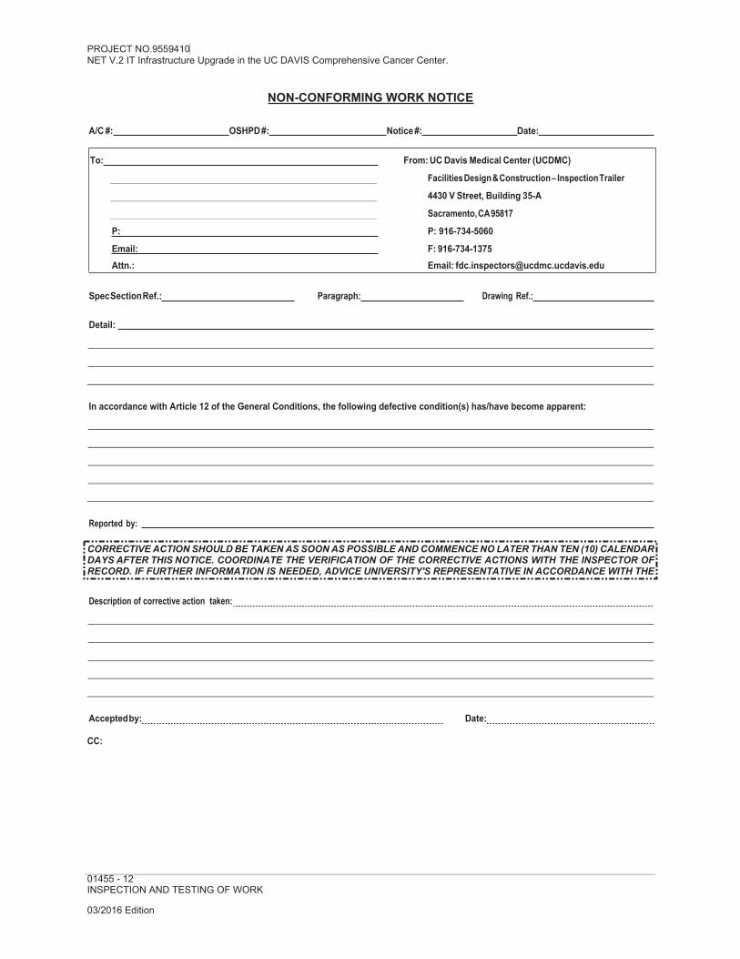
PROJECT NO.9559410NET V.2 IT Infrastructure Upgrade in the UC DAVIS Comprehensive Cancer Center.
03/2016 Edition
NON-CONFORMING WORK NOTICE
A/C #: OSHPD #: Notice #: Date:
To: From: UC Davis Medical Center (UCDMC)
Facilities Design & Construction – Inspection Trailer
4430 V Street, Building 35-A
Sacramento, CA 95817
P: P: 916-734-5060
Email: F: 916-734-1375Attn.: Email: [email protected]
Spec Section Ref.: Paragraph: Drawing Ref.:
Detail:
In accordance with Article 12 of the General Conditions, the following defective condition(s) has/have become apparent:
Reported by:
Description of corrective action taken:
Accepted by: Date:
CC:
01455 - 12INSPECTION AND TESTING OF WORK
CORRECTIVE ACTION SHOULD BE TAKEN AS SOON AS POSSIBLE AND COMMENCE NO LATER THAN TEN (10) CALENDAR DAYS AFTER THIS NOTICE. COORDINATE THE VERIFICATION OF THE CORRECTIVE ACTIONS WITH THE INSPECTOR OF RECORD. IF FURTHER INFORMATION IS NEEDED, ADVICE UNIVERSITY'S REPRESENTATIVE IN ACCORDANCE WITH THE GENERAL CONDITIONS.

PROJECT NO.9559410NET V.2 IT Infrastructure Upgrade in the UC DAVIS Comprehensive Cancer Center.
01510-1TEMPORARY UTILITIES
03/2016 Edition
SECTION 01510 TEMPORARY UTILITIES
PART I - GENERAL
1.01 SECTION INCLUDES
A. Temporary Power and Lighting.
B. Temporary Heating, Cooling & Ventilation.
C. Temporary Water.
D. Temporary Fire Protection.
E. Temporary Telephone.
1.02 RELATED SECTIONS
A. Section 01110 – SUMMARY OF THE WORK
B. Section 01350 – SPECIAL PROCEDURES: General requirements for temporary facilities and controls, to accommodate UCDMC occupancy and use of the areas and spaces adjacent to construction.
C. Section 01561 – AIRBORNE CONTAMINANTS CONTROL
D. Section 01740 – CLEANING
E. Section 01770 – CLOSEOUT PROCEDURES
1.03 TEMPORARY UTILITIES
A. Temporary Connections: Temporary power, water, sewer, gas and other utility services necessary for the Work may be made to existing building systems. Connections shall be subject to University's review and written approval. Coordinate with utility companies and University’s Plant Operations & Maintenance Department for locations and methods of connections.
B. Contractor shall provide and pay for installation, operation, maintenance, and removal of all utilities.
1.04 TEMPORARY POWER AND LIGHTING
A. Service Requirements:
1. Temporary Electrical Service: Contractor shall provide and pay for installation, operation, maintenance, and removal of temporary electrical service, lighting devices and restoration of existing and permanent equipment in accordance with applicable provisions of the Electrical Safety Orders of the State of California. Use of University’s electrical power and lighting system is prohibited without

PROJECT NO.9559410NET V.2 IT Infrastructure Upgrade in the UC DAVIS Comprehensive Cancer Center.
01510-2TEMPORARY UTILITIES03/2016 Edition
University’s written approval and will be considered only when an alternate electrical power source is unavailable.
a. Install initial services at time of site mobilization.
b. Modify and extend systems as Work requires.
c. Maintain electrical system to provide continuous service, including prompt restoration of interruptions to University systems when temporary service is connected.
d. Restore existing and permanent lighting used during construction to original condition. Replace defective fixtures, bulbs, and other component parts.
e. Clean existing and permanent lighting fixtures used during construction per Section 01740 – CLEANING.
2. Distribution: Contractor shall provide distribution network for temporary electrical power.
3. Power Source: Arrange for service with University’s Plant Operations and Maintenance Department, or local utility company.
4. Conformance: All temporary wiring and electrical facilities shall be in accordance with applicable provisions of Electrical Safety Orders of the State of California.
5. Temporary Lighting: Construction lighting shall be supplied and maintained by Contractor at Contractor's expense. Sufficient lighting levels shall be provided to allow construction to be properly and safely performed. Contractor shall give special attention to adequate lighting for stairs, ladders, floor openings, basements and similar spaces. Promptly replace burnt out, worn or defective parts.
6. Lighting fixtures: Locate fixtures in areas of Work: One (1) lamped fixture in rooms, except closets and utility chases; one (1) lamped fixture for every 750 square feet in large areas.
7. Security Lighting: Contractor shall provide security lighting during hours of low visibility.
B. Distribution requirements:C. Weatherproof distribution boxes with 0ne 240 volt, three phase power outlet and four 120 volt
outlets consisting of 100 amperes fused switches with equipment ground, spaced so a 100-foot extension cord will reach all areas of the building.
1. Wiring, connections and protection for temporary lighting.
2. Wiring connections and protection for temporary and permanent equipment, for environmental control, for temporary use of electricity operated equipment, and for testing.
D. Use of University System: If alternate electrical power and lighting sources are unavailable, University may permit Contractor to use existing, in-place electrical system. University does not guarantee availability of electrical power or adequate lighting levels through use of existing system. If power and lighting is insufficient or not available Contractor shall provide secondary source (i.e. generator) as approved by University.

PROJECT NO.9559410NET V.2 IT Infrastructure Upgrade in the UC DAVIS Comprehensive Cancer Center.
01510-3TEMPORARY UTILITIES
03/2016 Edition
1. It is expressly understood and agreed by Contractor that University existing power and lighting system's primary obligation is servicing patient care. The University system is not designed for purposes of construction activities.
2. Contractor should expect power and lighting interruptions during course of Work. Contractor will be required to cease use of University electrical-power and lighting systems, as required by the needs of University.
3. When use of University electrical system is approved in writing, Contractor is required to adhere to University's electrical lockout procedures. See Division 16 – Electrical.
a. Provide and maintain warning labels on energized equipment.
b. Replace plates, electrical devices or similar existing items or components damaged as a result of temporary usage.
1.05 TEMPORARY HEATING, COOLING AND VENTILATING
A. Service Requirements:
1. Contractor shall provide temporary heat as necessary for proper installation of all work and to protect all work and materials against injury from dampness and cold and to dry out building. Fuel, equipment and method shall be approved in writing by University’s Representative.
2. Install initial services at time of site mobilization. Modify and extend systems as Work requires.
3. Maintain systems to provide continuous service, including prompt restoration of interruptions to University systems when temporary service is connected.
4. Use of permanent heating system is preferred to any other system for maintaining temperature of building during installation of finish materials, but such use will not be permitted before clean-up after plastering and/or drywall work has been completed. Contractor shall make every effort to complete permanent heating system in time for such use. Permanent fans shall not be used before filters are
5. installed. Filters shall be cleaned and serviced by Contractor just prior to final acceptance.
6.7. Vent portable units to building exterior, complete with automatic controls. Direct-
fired units are not allowed. Locate units and outlets to provide uniform distribution of heating, cooling and ventilating.
8.9. Operate and maintain existing equipment being used; clean or replace filters and
install filters in duct extensions as necessary to maintain occupied areas, work areas and finished areas, in specified condition.
10.11. Prior to operation of permanent equipment, verify controls and safety devices are
complete, equipment has been tested, and inspection made and approved for operation.
12.13. Remove temporary materials and equipment when permanent system is
operational. Restore existing and permanent systems used for temporary purposes to original condition.
14.15. Install temporary filters in air handling units and ducts, replace as necessary to

PROJECT NO.9559410NET V.2 IT Infrastructure Upgrade in the UC DAVIS Comprehensive Cancer Center.
01510-4TEMPORARY UTILITIES03/2016 Edition
prevent dust in equipment and ducts, to avoid contaminants in Work or finished areas. After completion, replace temporary filters with new, clean, reusable filters.
16. Maintain temperature, humidity, and ventilation in enclosed areas to provide ambient conditions for storage, preparation and Work; to cure installed materials, to prevent condensation, to dry floor surfaces and to prevent accumulations of dust, fumes and gases.
17. During non-working hours maintain temperature in enclosed areas occupied solely by Contractor at a minimum of 50ºF., or higher as specified in individual Sections
and by individual product suppliers and manufacturers. Areas occupied in whole or in part by University are to be maintained at normal temperatures.
18. Provide high efficiency particulate air (HEPA) filters as specified in SECTION 01561 – AIRBORNE CONTAMINANTS CONTROL, negative pressure ventilation, or special control of existing system as determined by University’s Representative.
B. Utility Sources:
1. Electrical: As specified above in Item 1.04.
2. Existing mechanical systems may be used for temporary purposes. Coordinate use with University for conditions to be maintained in adjacent University occupied areas.
3. Contractor shall provide and pay for all installation, operation, maintenance and removal of equipment in accordance with applicable provisions of the Electrical Safety Orders of the State of California.
1.06 TEMPORARY WATER
A. Service Requirements:
1. Maintain systems to provide continuous service, including prompt restoration of interruptions to University’s systems when temporary service is connected.
2. Water service, if necessary for construction, can be made available at no expense to the Contractor provided the water is not wasted. Contractor shall be responsible for distribution of water to points of use.
3. Certified reduced pressure type back-flow prevention device as submitted to and approved by University shall be installed before water is obtained from a University campus fire hydrant or interior building connection.
B. Plumbing: Maintain system to provide continuous service with adequate pressure to outlets, including University system when temporary service is connected. See also Division 1 Approvals and ILSM requirements.
1. Size piping to supply construction needs, temporary fire protection, and for University’s needs when existing service is connected.
2. Disinfect piping used for drinking water. See Division 15 for requirements.
3. Source: University existing service, connect at locations as directed by University.
4. Provide valved outlets to control water pressure adequately for hoses.

PROJECT NO.9559410NET V.2 IT Infrastructure Upgrade in the UC DAVIS Comprehensive Cancer Center.
01510-5TEMPORARY UTILITIES
03/2016 Edition
5. Fire hydrants used for water supply for construction – Contractor must use only ” square hydrant wrench on square operating nut and must use only pentagon wrench on pentagon operating nut. This is to prevent damage to the hydrant operating nut. Any damage caused by the use of an improper wrench or other misuse of the hydrant must be repaired at contractor expense. Contractor mustinspect hydrant prior to use and make the University aware of any pre-existing damage.
C. Use of Existing System: Existing system may be used for temporary water. Monitor usage to prevent interference with University's normal operational requirements.
D. Use of Permanent System: Contractor shall obtain written agreement from University establishing start of warranty period and conditions of use.
E. Contractor shall pay for installation, operation maintenance and removal of system and restoration of existing and permanent equipment. University will pay costs of water consumed for normal construction operations. Contractor shall take measures to conserve usage.
1.07 TEMPORARY FIRE PROTECTION
A. Requirements:
1. Maintain systems to provide continuous service, including prompt restoration of interruptions to University systems when temporary service is connected.
2. Provide and maintain fire protection equipment including extinguishers, fire hoses and other equipment as necessary for proper fire protection during course of the Work.
3. Use fire protection equipment only for fighting fires.
4. Locate fire extinguishers in field offices, storage sheds, tool houses, other temporary buildings and throughout construction site. In area under construction, provide at least one (1) fire extinguisher for each 5,000 square feet of building floor area. Locate fire extinguishers so that a person never has to walk more that seventy-five (75) feet to obtain one.
5. Assign qualified person with authority to maintain fire protection equipment, institute fire prevention measures, and direct prompt removal of combustible and waste material. Submit ILSM requirements per Specification SECTION 01350 – SPECIAL PROCEDURES.
1.08 TEMPORARY TELEPHONE
A. Service Requirements:
1. Maintain systems to provide continuous service, including prompt restoration of interruptions to University systems when temporary service is connected.
2. Contractor shall select from the following options:
a. University shall provide conduit, cabling and dial tone to Contractor's location(s). Contractor shall pay University for cable, conduit installation and later removal of same and also pay University a monthly fee for use of University telephone system.

PROJECT NO.9559410NET V.2 IT Infrastructure Upgrade in the UC DAVIS Comprehensive Cancer Center.
01510-6TEMPORARY UTILITIES03/2016 Edition
b. University shall provide conduit and cabling to Contractor's location(s). Contractor shall receive dial tone from local utility. Contractor shall pay University for cabling, conduit installation, maintenance of same and later removal of same. Contractor shall pay local utility for monthly telephone service.
3. Contractor shall select number of lines, instruments and other features.
4. Contractor shall prepare and submit to University, "UNIVERSITY TELECOMMUNICATION TELEPHONE SERVICE FOR OUTSIDE CONTRACTORS" form. Refer to attached form at end of this section.
B. Use of Existing System: Existing University telephone system shall not be used for temporary telephone service.
C. Contractor Phone:
1. Contractor shall have telephone emergency number or other facility available at Contractor's business office for duration of contract where contractor andsuperintendent may be contacted within twenty-four (24) hours. Provide emergency numbers to University.
D. Telephones:
1. Contractor shall use, and only permit to be used, FCC approved communication devices on frequencies approved by FCC and University.
2. Contractor shall not use, or permit to be used, communication devices which interfere with existing University communication systems, including, but not limited to:
a. Life Flight or CHP helicopters.
b. Emergency Service vehicle communications.
c. Plant Operations & Maintenance communication devices.
d. Microwave transmission stations.
e. UCDMC closed-circuit television or radio signals.
f. Cellular or other mobile phone systems in main hospital.
g. UCDMC voice or digital paging systems.
PART II - PRODUCTS
2.01 MATERIALS
A. May be new or used, adequate to the purpose.
B. Devices and Equipment: Standard devices, meeting UL requirements.
C. Telephones: may be product of local service company or specialty devices compatible with service company requirements.

PROJECT NO.9559410NET V.2 IT Infrastructure Upgrade in the UC DAVIS Comprehensive Cancer Center.
01510-7TEMPORARY UTILITIES
03/2016 Edition
PART III - EXECUTION – Not Applicable to this Section
END OF SECTION 01510

PROJECT NO.9559410NET V.2 IT Infrastructure Upgrade in the UC DAVIS Comprehensive Cancer Center.
03/2016 Edition
UC Davis Health SystemTelephone Service for Construction Trailers/Work Sites
When construction bids are awarded, please include this form in the project packet. Contact Jim Fralick at 916-734-3399 or Amy Yee at 916-734-8000 in Telecommunications to verify the correct termination point for each project.
To order telephone service for your construction site at UC Davis Medical Center, please use the following instructions – see page 2 for additional information:
Call AT&T at “800-750-2355” to order your telephone lines. You will need to give them the following information:
a. Bring service to: 2315 Stockton Blvd, Sacramento, CA – 1.1 MPOE, Admin Bldg (or other location as designated)
b. Site contact person: Amy Yee, 916-734-8000c. Request the installer to call Amy Yee with binding post information
AT&T will provide the new assigned telephone numbers, an order number and the installation date. Enter the information onto the form below. Fax the completed form to: UC Davis Medical Center, Telecommunications
Fax # 916-456-8331Attention: Amy Yee – 916-734-8000
Date: Project Name:
Company Name:
Contact Name:
Phone or Cellular #: Email address: Location of construction site:
UCDHS Project Manager:
Phone #:
AT&T Order Information
Telephone number assignments:
AT&T Order #: Pacific Bell due date:
Note: This form is to be used for ALL telephone services ordered for this project, including Fax Lines, Modem/DSL Lines and Payphones.
01510-9TEMPORARY UTILITIES
UCDMC Project Managers
CONTRACTORS

PROJECT NO.9559410NET V.2 IT Infrastructure Upgrade in the UC DAVIS Comprehensive Cancer Center.
03/2016 Edition
The following are typical telephone system safety practices required by the subs to get site- accessed phone, T1, DSL and fax services:
1. Cabling from the University splice point to the trailer needs to be "pic" (gel filled) outside plant cable (Superior Essex-Sealpic-24 ga, 6, 12 pair, Graybar cut to length) protection against the elements and accidental faults. Requires 8-foot minimum pigtail at the splice box.
2. DMARC at trailer needs to have a primary protection module (Sec 800-30&41 CEC-2002, found at Graybar) with 2, 4, 6, 8, pair protection to receive the cable from the splice.
3. 1-8 foot copper coated ground rod placed at the trailer and wired by an electrician to the trailer power ground (building) and Telephone primary protector module.
UC Davis Medical Center contact for additional information: Jim Fralick – 916-734-3399
01510-10TEMPORARY UTILITIES


PROJECT NO.9559410NET V.2 IT Infrastructure Upgrade in the UC DAVIS Comprehensive Cancer Center.
01520 - 1CONSTRUCTION FACILITIES
03/2016 Edition
SECTION 01520 CONSTRUCTION FACILITIES
PART I - GENERAL
1.01 SECTION INCLUDES
A. Field Offices and Sheds
B. Temporary Facilities
C. Temporary Sanitary Facilities
1.02 RELATED SECTIONS
A. Section 01110 – SUMMARY OF THE WORK
B. Section 01350 – SPECIAL PROCEDURES: General requirements for temporary facilities and temporary controls to accommodate University continued occupancy, and use of the areas and spaces adjacent to construction.
C. Section 01740 – CLEANING
D. Section 01770 – CLOSEOUT PROCEDURES
1.03 FIELD OFFICES AND SHEDS
A. Field Office: Contractor shall provide a job office that will conform to the following minimum requirements:
1. Suitable space for drawings, specifications, samples and other project records.
2. Conference space for eight (8) persons, including layout tables.
3. Heating and cooling to maintain a reasonable working environment.
4. Telephone service as specified in Section 01510 – TEMPORARY UTILITIES
5. Furnishings required: Conference table and chairs; racks and files for Contract Documents, submittals, and project record documents. Other furnishings are at Contractor's option.
B. Installation: Install office spaces for occupancy fifteen (15) calendar days after date of University/Contractor agreement.
C. Preparation: Fill and grade sites for temporary structures to provide drainage away from buildings.


PROJECT NO.9559410NET V.2 IT Infrastructure Upgrade in the UC DAVIS Comprehensive Cancer Center.
01560 - 1TEMPORARY BARRIERS, ENCLOSURES AND CONTROLS
03/2016 Edition
D. Contract Documents: Complete set of Contract Drawings and Contract Specifications shall be kept continuously at the site. Copies of all Change Orders, letters, Shop Drawings, etc., shall be kept on the job-site at all times and shall be available for inspector's use.
E. Contact numbers: Contractor shall provide telephone numbers where Contractor may be reached at all times during normal working hours and also after normal working hours, if emergency problems develop that require Contractor's assistance.
F. Storage Sheds and Containers for Materials, Tools and Equipment: If requested, University will provide space outside construction site where Contractor may provide and locate weather-tight sheds or containers for storage of construction materials, tools and equipment. Contractor shall be solely responsible for security of such sheds and containers. Size storage requirements to allow access, orderly provision of maintenance and inspection of products.
G. Cleaning: Weekly janitorial services for offices; periodic cleaning and maintenance for office and storage areas. Contractor shall keep construction loading and parking areas clear of construction debris, especially debris that may cause slipping or tripping hazardthat may injure vehicle tires, that may stain surfaces, and that may be tracked into existing buildings. Maintain approach walks free of mud and water.
H. Removal: Upon completion of the work, and before the final payment, Contractor shall remove all temporary work and facilities and return site to condition required by the General Conditions of the Contract and at no change to the Contract Sum or the Contract Time.
1.04 TEMPORARY FACILITIES
A. Contractor shall provide and maintain the following temporary facilities as required for execution of the Work:
1. Scaffolding, staging, runways and similar equipment.
2. Hoists or construction elevators, complete with operators, power and signals required.
3. Temporary rigging, rubbish chutes, barricades around openings, ladders between floors, and similar equipment.
4. Barricades, fencing, lights and similar safety precautions.
B. Maintenance: Use all means necessary to maintain temporary construction facilities and controls in proper and safe condition throughout progress of the Work.
C. Replacement: In event of loss or damage, promptly restore temporary construction facilities and controls by repair or replacement at no change to the Contract Sum or the Contract Time.
D. Conformance: All materials and equipment required to safely accomplish work under this Section shall be in conformance with requirements of CAL OSHA and other State and Federal Codes and regulations where applicable.
E. Codes: All temporary work and facilities shall conform to the above requirements that pertain to operation, safety and fire hazard.
F. Construction Site Security: Temporary barriers, doors and gates shall be keyed to University’s master lock system. Security hardware to be provided by Contractor. Keying to University master lock system will be provided by University.

PROJECT NO.9559410NET V.2 IT Infrastructure Upgrade in the UC DAVIS Comprehensive Cancer Center.
01560 - 2TEMPORARY BARRIERS, ENCLOSURES AND CONTROLS03/2016 Edition
1.05 TEMPORARY SANITARY FACILITIES
A. Use of existing facilities: Designated toilet facilities may be used by Contractor.
1. Assigned facilities: Location of assigned toilet facilities and maintenance of same are responsibility of University. Contractor shall not have exclusive use to these
facilities and shall abide by health and safety criteria regarding their use and sanitary upkeep.
2. Unassigned facilities: Unassigned toilet facilities shall not be used without written authorization of University's Representative.
3. Contractor may use existing toilet facilities that are within the limits of the Work.
B. Contractor shall pay service charges for connection and use of sewage utilities.
C. Portable units: Enclosed, portable, self-contained units or temporary water closets and urinals, secluded from public view may be used. Self-contained units shall be approved by University's Representative prior to use.
1. Contractor shall pay costs of installation, maintenance and removal of temporary sanitary facilities.
2. Provide facilities at time of site mobilization.
3. Modify and extend services as work progress requires.
4. When utility services are available, provide water, sewer service, and temporary water closets; remove portable facilities. Remove temporary fixtures when permanent facilities are operational.
5. Clean areas of facilities daily, maintain in sanitary condition. Disinfect fixtures, repair or replace damaged fixtures, accessories and surfaces.
6. Provide toilet paper, paper towels, and soap in suitable dispensers.
7. Restore existing and permanent areas and facilities used to original condition.
PART II - PRODUCTS
2.01 MATERIALS
A. Serviceable, new or used, adequate for required purpose.
PART III - EXECUTION – Not Applicable to this Section
END OF SECTION 01520

PROJECT NO.9559410NET V.2 IT Infrastructure Upgrade in the UC DAVIS Comprehensive Cancer Center.
01560 - 3TEMPORARY BARRIERS, ENCLOSURES AND CONTROLS
03/2016 Edition
SECTION 01550 VEHICULAR ACCESS AND PARKING
PART I - GENERAL
1.01 SECTION INCLUDES
A. Construction Parking and Access Roads
B. Traffic Regulation
C. Project Informational Signs
1.02 RELATED SECTIONS
A. Section 01110 – SUMMARY OF THE WORK
B. Section 01330 – SHOP DRAWINGS, PRODUCT DATA AND SAMPLES
C. Section 01350 – SPECIAL PROCEDURES: General requirements for temporary facilities and temporary controls to accommodate University's continued occupancy and use of the areas and spaces adjacent to construction.
D. Section 01740 – CLEANING
E. Section 01770 – CLOSEOUT PROCEDURES: Project Closeout.
1.03 PARKING AREAS AND ACCESS ROADS
A. Access Roads: Existing roads shall be used for construction access within limits defined herein. Temporary construction access roads shall not be permitted.
B. Parking: Parking is controlled and limited by University.
1. Parking of personal vehicles belonging to Contractor employees may be arranged with University's Parking Services, at 916-734-2687. Parking will be allowed in
employee permit areas, at the current permit rates depending on space availability. All permits must be purchased on cash basis.
2. Delivery of materials may be made to the job-site as required. Contractor shall coordinate with University's Representative.
3. Dumpsters shall be located in approved location as arranged by University's Representative.
C. Existing Pavements and Parking Areas: Designated existing on-site streets and driveways may be used for construction traffic. Vehicles with metal tracks will not be allowed.
1. Designated areas of existing parking facilities may be used by construction personnel. Do not allow heavy vehicles or construction equipment in parking areas.
2. Maintain traffic and parking areas in a sound condition, free of excavating material, construction equipment, products, mud, snow and ice.

PROJECT NO.9559410NET V.2 IT Infrastructure Upgrade in the UC DAVIS Comprehensive Cancer Center.
01560 - 4TEMPORARY BARRIERS, ENCLOSURES AND CONTROLS03/2016 Edition
3. Maintain existing and permanent paved areas used for construction. Repair existing facilities damaged by usage to original condition: promptly repair breaks, potholes, low areas, standing water and other deficiencies, to maintain paving and drainage in original or specified condition.
4. Remove temporary materials and construction when permanent paving is usable.
1.04 TRAFFIC REGULATION
A. Schedule of Access Closing: Contractor shall adopt all practical means to minimize interference to traffic. Access to other facilities in the area shall be maintained at all times. Contractor shall provide schedule of planned closing of any street for approval by University and shall give minimum of fourteen (14) calendar days notice before closing any street or access.
B. Use of Fire Lanes: Contractor shall notify University of all major pickups and deliveries that require use of controlled access fire lanes. Keys to gates or other barriers will be provided, as needed, to allow use of fire lanes. Vehicles parked in fire lanes for delivery of materials shall be continuously manned for immediate removal if required by the University.
C. All major pick-up and delivery operations shall occur in total before or after normal working hours.
1. Drawings may indicate haul routes designated by University for use of construction traffic. Confine construction traffic to haul routes.
2. Provide traffic control at critical areas of haul routes to regulate traffic and minimize interference with public traffic.
D. Post-mounted and wall-mounted traffic control and informational signs as specified herein.
1. Traffic Control Signs, Cones, Drums, Flares, Lights and Flag Control equipment: All as approved by local jurisdiction.
2. Contractor shall furnish at all barricades: Lights and flag control required to control traffic, and shall also provide and maintain suitable temporary barricades, fences, directional signs, or other structures as required for protection of the public; and
maintain from the beginning of twilight throughout the whole of every night on or near the obstructions, sufficient lights and barricades to protect the public and/or the Work.
E. Construction Vehicle Parking: Control vehicular parking to prevent interference with public traffic and parking, access by emergency vehicles, and University’s operations. Prevent parking on or adjacent to roads or in non-designated areas.
F. Flag Control: Provide properly trained and equipped flagmen to regulate vehicular traffic when construction operations or traffic encroach on public traffic ways.
1. Provide properly trained and equipped personnel to regulate pedestrian traffic at all interior locations where construction traffic interfaces with University traffic.
2. Flag control personnel shall wear appropriate identifying clothing such as bright colored vests, clearly visible and identifiable as having responsibility for traffic control.

PROJECT NO.9559410NET V.2 IT Infrastructure Upgrade in the UC DAVIS Comprehensive Cancer Center.
01560 - 5TEMPORARY BARRIERS, ENCLOSURES AND CONTROLS
03/2016 Edition
G. Lights: Use lights during hours of low visibility to delineate traffic lanes and to guide traffic.
H. Traffic Signs and Signals: At approaches to site and on site, install traffic signs and signals at crossroads, detours, parking areas, and elsewhere as needed to direct construction and affected public traffic.
1. Install and operate traffic control signals to direct and maintain orderly flow of traffic in areas under Contractor's control, and areas affected by Contractor's operations.
2. Relocate traffic signs and signals as Work progresses, to maintain effective traffic control.
3. Remove equipment and devices when no longer required. Repair damage caused by installation.
1.05 PROJECT INFORMATIONAL SIGNS
A. Project Identification Sign: Contractor shall provide one (1) project sign. Sign will consist of one (1) 8’ x 4’x ¾” exterior grade plywood with medium or high density phenolic sheet overlay, painted plywood sign on fence area at construction field office or yard.
1. Information on sign shall include PROJECT NAME, University of California, Davis Medical Center, University’s consultants, etc. Copy will be provided by the University.
B. Painted Informational Signs: Provide at each field office, storage shed and yard, directional signs to direct traffic into and within site. Relocate as Work progress requires.
C. Maintain signs and supports: Clean, repair deterioration and damages.
D. Remove signs, framing, supports and foundations at completion of Project and restore the area.
PART II - PRODUCTS – Not Applicable to this Section
PART III - EXECUTION – Not Applicable to this Section
END OF SECTION 01550

PROJECT NO.9559410NET V.2 IT Infrastructure Upgrade in the UC DAVIS Comprehensive Cancer Center.
01560 - 6TEMPORARY BARRIERS, ENCLOSURES AND CONTROLS03/2016 Edition
SECTION 01560TEMPORARY BARRIERS, ENCLOSURES AND CONTROLS
PART I - GENERAL
1.01 SECTION INCLUDES
A. Barriers and Enclosures
B. Protected Walkways and Weather Closures
C. Tree and Plant Protection
D. Temporary Controls
1.02 RELATED SECTIONS
A. Section 01110 – SUMMARY OF THE WORK
B. Section 01350 – SPECIAL PROCEDURES
C. Section 01561 – AIRBORNE CONTAMINANTS CONTROL
D. Section 01740 – CLEANING
1.03 BARRIERS AND ENCLOSURES
A. Barricades: Provide to prevent public entry, to protect existing trees and plants, and to protect existing facilities and adjacent properties from damage during construction period. Relocate and extend as construction progress requires.
B. Partitions and Ceiling Enclosures:
1. Fire Enclosures-Rated-Corridors and Rated Assemblies: Provide non-combustible dust-proof barrier framed with metal studs spaced 24" o/c maximum and covered on both sides with " thick Type-X rated gypsum wallboard taped, braced so to be self supporting without fastening to existing finishes.
a. Provide gaskets of closed cell neoprene, or strips of fiberglass insulation between barriers and existing finish.
b. Finish exposed surfaces with two (2) coats of paint (color as selected by University), maintain in neat, orderly appearance and paint barrier on public side. Temporary emergency exit and or directional signage indicating Emergency Exits will be furnished and installed by Contractor.
c. Provide temporary doors in corridors with twenty (20) minute fire-rated assemblies and locksets to limit use.
d. Use of access doors and routes by workmen to be approved by University's Representative.
PROJECT NO.9559410NET V.2 IT Infrastructure Upgrade in the UC DAVIS Comprehensive Cancer Center.
01560 - 7TEMPORARY BARRIERS, ENCLOSURES AND CONTROLS
03/2016 Edition
2. Fire Retardant Enclosures - Non-Rated Assemblies: Provide non-combustible dust-proof barriers framed with metal studs and covered on public side with Fire Retardant plastic laminate sheathing material. Flame spread 10 - smoke development 45 - fuel contribution undeterminable, as manufactured by Reef Industries, Inc., P.O. Box 33248, Houston, TX 77033 or equal.
a. Joints shall be taped and sealed over framing studs.
b. Bracing shall be self-supporting without fastening to existing finishes.
c. Provide gaskets of closed cell neoprene, or strips of fiberglass insulation between barriers and existing finishes.
d. Provide non-staining taped seal to surrounding materials to insure seal.
e. Non-Rated Assemblies for Dust Control: Use ½" Type-X or equal gypsum wallboard applied on occupancy side on framing member. Joints over studs shall be taped and sealed. Other detail similar to 1.03-B.2 above.
C. Removal: Remove temporary materials, equipment and construction at completion; repair damage caused by installation or use of barricades and enclosures. Restore existing facilities used during construction to specified, or to original condition.
1.04 PROTECTED WALKWAYS AND WEATHER CLOSURES
A. Cover walkways to provide access to existing facilities for use by public and University personnel.
B. Provide temporary roofing and weather-tight insulated closures of openings in exterior wall surfaces, to maintain specified working conditions, to protect products and finished work from inclement weather.
1.05 TREE AND PLANT PROTECTION
A. Tree Protection: All trees not marked for removal shall be protected against damage from construction operations. Where necessary, in the opinion of University's Representative, trees surrounding building footprint or in close proximity to construction operation shall be protected with barricades. No trees shall be cut or felled without approval of University's Representative. Trees cut and/or removed without explicit instruction shall be replaced by Contractor at no cost to University.
B. Cutting and Pruning: Cutting and pruning of trees to accommodate construction shall be done only with approval and direction by University's Representative. Soil within the spread of tree branches (within drip line) shall not be disturbed except as directed by excavation or trenching drawings. Advance notice shall be given University if tree roots of 3"diameter or greater must be cut.
C. Drip line Protection: Cars, trucks, or equipment shall NOT be parked or set within the drip line of any tree; nor shall there be any stockpiling or temporary building erected within the drip line.

PROJECT NO.9559410NET V.2 IT Infrastructure Upgrade in the UC DAVIS Comprehensive Cancer Center.
03/2016 Edition
1.06 TEMPORARY CONTROLS
A. Dust Control: Contractor shall take appropriate steps throughout project to prohibit airborne dust due to work under this contract. Execute work by methods to minimize raising dust from construction operations. Water shall be applied wherever practical to settle and hold dust to minimum, particularly during demolition and moving of materials. No chemical dust prohibitor shall be used without written approval by University's Representative.
B. Noise Control: Control noise as directed by University's Representative.
C. Pollution Control: Use of noxious or toxic materials for all applications in alterations or work in buildings occupied by University personnel shall be done after proper notification and approval by University, this includes work performed on weekends or other unoccupied times.
1. Provide methods, means and facilities to prevent contamination of soil, water and atmosphere from discharge of noxious, toxic substances and pollutants produced by construction operations.
D. Waste Control: All waste materials resulting from process of clearing and construction shall be disposed of as follows:
1. General Refuse: All refuse and debris, combustible and incombustible, resulting from construction process, shall be removed from University property as described in the General Conditions of the Contract. Contractor shall not use any refuse container belonging to University.
2. Hazardous Refuse: Solvents, oils and any other hazardous material shall be disposed of in containers and removed from site. At completion of work, any contaminated soil shall be removed and replaced with good soil by Contractor at no expense to University. Coordinate disposal with UCDMC EH&S department.
3. All material and equipment removed as part of the Project is property of University, unless specifically designated otherwise; such material and equipment shall be delivered to a location at Medical Center, as directed by University, to be selectively sorted by University; remaining debris shall be disposed of by Contractor at no expense to University.
E. Drainage Control: All portions of Work shall be kept free of standing water at all times during construction. Where required, temporary drainage ditches, berms, or pumping systems shall be constructed to divert drainage water from construction site, and resultant water shall be carried to nearest natural water course and disposed of without erosion to surrounding area. Care shall be taken to prevent silting of existing sinkholes and water-
01560 - 3TEMPORARY BARRIERS, ENCLOSURES AND CONTROLS

PROJECT NO.9559410NET V.2 IT Infrastructure Upgrade in the UC DAVIS Comprehensive Cancer Center.
03/2016 Edition
courses. Silt deposited as a result of the Work shall be removed and disposed of by Contractor at no cost to University.
1. Rough grade site to prevent standing water and to direct surface drainage away from excavations, trenches, adjoining properties and public right-of-ways.
2. Maintain excavations and trenches free of water. Provide and operate pumping equipment of a capacity to control water flow.
3. Provide de-watering system and pumping to maintain excavations dry and free of water inflow on a twenty-four (24) hour basis.
4. Provide piping to handle pumping outflow to discharge in manner to avoid erosion or deposit of silt. Provide settling basins to avoid silting; install erosion control at out-falls of system.
5. Remove equipment and installation when no longer needed.
F. Sediment and Erosion Control: Contractor shall furnish, install and maintain means and methods to reduce excessive erosion, minimize sedimentation discharge, and prevent construction materials discharge from causing off-site and on-site contamination. Contractor shall coordinate with University.
1. Contractor shall pay for and maintain required permits.
2. Contractor shall furnish:
a. National Pollutant Discharge Elimination (NPDE) permit.
b. Contractor shall file Notice of Intent to California State Water Resources Control Board (SWRCB) stating date construction will begin. Provide copy to University.
c. Contractor shall prepare, maintain and follow Storm Water prevention Plan. The Plan shall include Contractor's Best Management Practices (BMP) describing means and methods to control sediment, erosion and other pollutants.
d. Contractor shall keep BMP Program at job-site.
PART II - PRODUCTS – Not Applicable to this Section
PART III - EXECUTION – Not Applicable to this Section
END OF SECTION 01560
01560 - 4TEMPORARY BARRIERS, ENCLOSURES AND CONTROLS

PROJECT NO.9559410NET V.2 IT Infrastructure Upgrade in the UC DAVIS Comprehensive Cancer Center.
01561 - 10AIRBORNE CONTAMINANTS CONTROL03/2016 Edition
SECTION 01561AIRBORNE CONTAMINANTS CONTROL
PART I - GENERAL
1.01 SUMMARY
A. Section Includes: University airborne contaminants control policy procedures and an Infection Control Risk Assessment (ICRA) and plan.
1.02 POLICY
A. Airborne contaminants control is critical in all hospital areas. Contractor shall limit dissemination of airborne contaminants produced by construction-related activities, including dust, chalk, powders, aerosols, fumes, fibers and other similar materials, in order to provide protection of immuno-compromised and other patients, staff, diagnostic operations, or sensitive procedures or equipment, from possible undesirable effects of exposure to such contaminants.
1. Dust in ceilings and construction debris contains fungus, which if inhaled by patients, can cause pneumonia and even death. Construction activities causing disturbance of existing dust, or creating new dust, or other airborne contaminants, must be conducted in tight enclosures cutting off any flow of particles into patient areas.
2. Ceilings, walls in Protection Areas and other areas in Hospitals as indicated on drawings must be secure at all times.
B. An Infection Control Risk Assessment (ICRA) and plan to mitigate dust is required for each project. The risk assessment identifies patient groups at risk for infection due to construction dust. The dust mitigation plan is designed to contain dust within the construction zone. Some hospitalized patients are fragile. These patients are at risk for acquiring infections from bacteria and viruses that are transported on air currents from the construction zone to the patient areas. Dust is a method for germs to move through the hospital. The ICRA and dust mitigation plan assures a clean, safe environment for the patients hospitalized during construction. Hospital management is expecting your assistance in providing the best possible environment for the patients. We appreciate your
partnership in the campaign to prevent a hospital acquired infection related to construction dust.
C. Related Sections:
1. Section 01730 – CUTTING AND PATCHING: Removal of debris may be outside of normal work hours and shall be in tightly covered containers.
2. Section 01350 – SPECIAL PROCEDURES: Perform work in accordance with requirements of this section.
3. Section 01510 – TEMPORARY UTILITIES: Provide high efficiency particulate air (HEPA) filters as specified in Section 01561, negative pressure ventilation, or special control of existing system as determined by University's Representative.

PROJECT NO.9559410NET V.2 IT Infrastructure Upgrade in the UC DAVIS Comprehensive Cancer Center.
01561 - 11AIRBORNE CONTAMINANTS CONTROL
03/2016 Edition
4. Section 01560 – TEMPORARY BARRIERS, ENCLOSURESAND CONTROLS: Extend barriers above ceilings as required to seal off and contain airborne contaminants.
5. Section 01560 – TEMPORARY CONTROLS: Contain waste materials during removal; bagging, wrapping, and transporting.
6. Section 01740 – CLEANING: Use wet cleaning methods and HEPA-filtered vacuum cleaners as required to minimize release of airborne contaminants. Contain waste materials, debris and rubbish as noted above. Disinfect Containment and Protection Areas as directed by University's Representative
D. Dust Mitigation Requirements for Category I
1. An ICRA Daily Compliance Survey is also attached at the end of this section. The Contractor must complete and submit this daily checklist to the University’sRepresentative. Any areas of non-compliance must be specifically listed and addressed for corrective measures when identified.
2. Other mitigations as listed by classification are shown on page 11 of this section.
1.03 SUBMITTALS
A. Submit to Project Inspector Daily ICRA Compliance Survey.
B. Schedules: Submit work areas and procedure schedules for containment of airborne contaminants.
C. Work Plan: Drawings and details of construction of necessary temporary barriers, and description of procedures to be used to achieve and maintain control of construction- related airborne contaminants.
1.04 QUALITY CONTROL
A. Pre-construction Meeting: Before any construction on site begins, Contractor’s Superintendent is required to attend a mandatory pre-construction orientation session held by University's Representative for training and instruction on precautions to be taken.
B. A written report from a qualified air balance regulator shall be submitted confirming specified air velocity whenever a barricade is erected or modified in designated Protection Area. Negative air machines shall be connected to emergency power and run continuously.
C. Notification: A minimum of fourteen (14) calendar days written notification to University's Representative of possible construction activity causing airborne contaminants in Protection Areas.
D. Training: There will be ICRA training for Contractor’s and crews prior to issuance of Security Badge and start of work.
1.05 TESTING
A. Air Samples: University will provide baseline particle counts and conduct periodic air sampling of Protection Areas during construction to monitor effectiveness of containment procedures.
B. Air Pressure: Using visual indicators, University will verify the maintenance of negative air pressure in Containment Area relative to Protection Areas on a daily basis.

PROJECT NO.9559410NET V.2 IT Infrastructure Upgrade in the UC DAVIS Comprehensive Cancer Center.
01561 - 12AIRBORNE CONTAMINANTS CONTROL03/2016 Edition
1.06 DEFINITIONS
A. Contaminant producing activities include, but are not limited to:
1. Demolition and removal of walls, floors, ceilings, and other finish materials.
2. Demolition of plumbing, mechanical and electrical systems and equipment.
3. Finish operations such as sanding, painting, and application of special surface coatings.
B. Containment Areas: As determined by University's Representative and as shown. Includes area of construction, adjacent staging and storage areas, and passage areas for workers, supplies and waste; includes ceiling spaces above and adjacent to construction, if shown.
C. Protection Areas: As determined by University's Representative and as shown as Protection Areas. Includes hospital areas adjacent to Containment Area, either occupiedor used for passage, as well as areas connected to construction area by mechanical system air intake, exhaust and ductwork.
1.07 PERFORMANCE REQUIREMENTS
A. University's Representative's Responsibilities:
1. Determination of the Containment and Protection Areas, as well as the standard of limitations of the Contractor's responsibilities, required for the project.
2. Statement of Requirements: Description in graphic and written form as required to communicate the above based on evaluation of the construction area and the impact of the project on patient care.
B. University's Responsibilities:
1. Assist University's Representative to determine Containment and Protection Areas.
2. Perform testing and monitoring as specified.
C. Contractor's Responsibilities:
1. Specific means and methods of achieving and maintaining control of airborne contaminants during construction.
2. Contractor’s shall implement all mitigation measures as listed in the ICRA/Dust Mitigation Plan, Class IV.
3. Contractor shall ensure that all workers are trained and adhere to the mitigation requirements.
4. Notification: Contractor shall notify University's Representative in writing, a minimum of fourteen (14) calendar days prior to starting construction activity, which
PROJECT NO.9559410NET V.2 IT Infrastructure Upgrade in the UC DAVIS Comprehensive Cancer Center.
01561 - 13AIRBORNE CONTAMINANTS CONTROL
03/2016 Edition
might be expected to produce excess levels of airborne contaminants in containment area so that additional precautions may be taken.
PART II - PRODUCTS
2.01 MATERIALS
A. Carpet or Mats: Provide at barricade entrances, vacuumed or changed as often as necessary to prevent accumulation of dust.
B. Dust Caps: Block off all existing ventilation ducts within the construction area. Method of capping ducts shall be dust tight and withstand airflow.
C. Portable Enclosures: Whenever openings are made into existing ceilings, provide portable enclosure enclosing ladder and sealing off opening, fitted tight to ceiling. Refer to Section 01560 for requirements.
D. Polyethylene: Polyethylene shall be fire retardant type listed by Fire Underwriter's Laboratories, Griffolyn #T55R with Griffolyn fire retardant tape, or equal, (no known equal).
PART III - EXECUTION
3.01 INSPECTION
A. Before any demolition or construction begins, a complete field review of all Protection Areas (infection control areas) and policies will be conducted and work plan revised if required by Contractor, Inspector and UCDMC Environmental Health & Safety Personnel.
3.02 CONTAINMENT
A. Requirement: Maintain levels of airborne contaminants within limits as defined.
3.03 PROTECTION
A. General: Contractors shall completely comply with the ICRA/Dust Mitigation Plan, Class IV at the end of this section. Provide and maintain all barriers, filters, ventilation, and cleaning and removal procedures as detailed in work plan.
B. Sealing of Openings: Use duct-tape or other impenetrable sealant to seal barrier wall seams, cracks around window and doorframes, exhaust system ductwork, pipes, joints and ducts.
C. Dust Control: The Contractor shall take appropriate steps throughout the term of the Project to prevent airborne dust due to work under this contract. Water shall be applied wherever practical to settle and hold dust to a minimum, particularly during demolition and moving of materials. No chemical palliatives shall be used without permission of the University's Representative.
1. Spray surfaces with water during dust-producing interior demolition activities. Hard surface floors in work area, adjacent hallways and passage areas require vacuuming with HEPA-filtered vacuum cleaners and frequent wet-mopping during

PROJECT NO.9559410NET V.2 IT Infrastructure Upgrade in the UC DAVIS Comprehensive Cancer Center.
01561 - 14AIRBORNE CONTAMINANTS CONTROL03/2016 Edition
demolition and construction; protect adjacent carpeted areas with plastic and plywood and vacuum with HEPA-filtered vacuum cleaners.
2. Execute work by methods to minimize raising dust from construction operations. Provide positive means to prevent airborne dust from dispersing into atmosphere.
3. Any dust tracked outside of barrier shall be removed immediately.
D. Airborne contaminant barriers or infection control barriers shall be dust-tight. Any dust tracked outside of barrier shall be removed immediately, as specified. All cleaning outside barrier should be by HEPA-filtered vacuum or other approved method.
E. Negative air machines as described herein shall provide airflow into construction area not less than 100 fpm at barricade entrances with doors fully open.
F. Air Quality Infection Control: Fasten windows shut, ventilate barricaded construction areas by use of negative air machines exhausted through filters to the outside of building.
1. Provide a minimum of 2 negative air machines and cease any demolition in high- risk areas not services by negative air machines. Vent negative air machines to outside by removing existing windows and replacing them with vented sheet metalpanels having fittings for exhaust holes. Provide added local exhaust during welding.
2. Maintain a minimum airflow of 100 ±10 FPM with door fully open at barricade entrance openings.
3. Change HEPA-filters as frequently as necessary for duration of the project to maintain a negative pressure of 0.02" WG in the construction area and filter particles as small as 0.12 microns in size.
4. Negative air units are to be DOP tested and certified prior to being placed in service, after a HEPA filter change, and when dropped or damaged or moved extensively.
G. Workers: Instruct workers to refrain from tracking dust into adjacent hospital areas or opening windows or doors that allows airborne contaminants into adjacent hospital areas.
H. Exterior Work: The Contractors will, at their own expense, direct exhaust from equipment away from building air intakes; assure that filters on building air intakes are operational and protected from excessive amounts of airborne contaminants.
I. Any ceiling access panels opened for investigation beyond sealed areas shall be replaced immediately when unattended.
1. Whenever access panels are opened in occupied areas, for work above ceilings, provide duct tight polyethylene enclosure enclosing ladder and sealing off opening, fitted tight to ceiling.
J. Provide thorough cleaning of existing surfaces, which become exposed to dust, before start of University's room occupancy.
K. Removal of construction barriers and ceiling protection shall be done carefully, in Protection Areas (Infection Control), possibly outside of normal work hours. Vacuum and clean all surfaces free of dust after the removal.

PROJECT NO.9559410NET V.2 IT Infrastructure Upgrade in the UC DAVIS Comprehensive Cancer Center.
01561 - 15AIRBORNE CONTAMINANTS CONTROL
03/2016 Edition
L. All vacuuming outside areas not under negative pressure shall be with a certified HEPA- filtered vacuum as described.
M. All removal of debris shall occur daily and deposited to the outside in tightly covered containers.
N. Contractor must block off or install temporary filters at existing ventilation intakes that may receive dust from construction area.
O. All polyethylene and other materials used for temporary enclosures shall be fire retardant type.
3.04 ENFORCEMENT
A. Process: Failure to maintain required containment will result in issuance of written warning; if situation is not corrected within eight (8) hours of receipt of warning, University will have cause to stop the work as provided in Article 2.1 of the General Conditions. Any egregious violation of safety requirements shall be grounds for Immediate Work Stoppage.
3.05 SCHEDULE OF REQUIREMENTS
A. Baseline levels of dust particles and Aspergillus spores in Protection Areas and levels not to be exceeded during construction are shown on the following page.
END OF SECTION 01561

PROJECT NO.9559410NET V.2 IT Infrastructure Upgrade in the UC DAVIS Comprehensive Cancer Center.
01561 - 10AIRBORNE CONTAMINANTS CONTROL07/2014 Edition
ICRA TRAINING TEST FOR CONSTRUCTION PERSONNEL
NAME:
EMPLOYER:
DATE:
PROJECT:
1. What is the reason for keeping the construction zone clean and dust free?
a. To make sure patients do not develop illness caused by construction dust.
b. To keep the dust particles in the air at a minimum because dust can carry germs through the air to the patients and cause illness.
c. Both a. and b.
2. A project can be shut down if there is too much dust.
a. True
b. False
3. Circle each way you can prevent dust from getting into patient areas.
a. Enter and leave the construction zone on the designated path assigned by the project coordinator.
b. Wash my hands when leaving the construction zone.
c. Walk over the tacky mats to remove dust from my shoes.
d. Don’t go into public areas with dust on my clothing. I remove dust from my clothing before leaving the construction zone.
e. Make sure all demolition materials are placed in a closed, sealed container before taking it outside. I use the egress designated for the crew.
f. Floors are damp mopped hourly to keep them dust free.
g. I use a HEPA filter vacuum to clean dust from floors for Class IV activities. Brooms create too much dust.

PROJECT NO.9559410NET V.2 IT Infrastructure Upgrade in the UC DAVIS Comprehensive Cancer Center.
01561 - 11AIRBORNE CONTAMINANTS CONTROL
03/2016 Edition
DAILY ICRA COMPLIANCE SURVEY
DATE
BARRIERS
TIME
Appropriate for patient population/project yes noCOMMENT:
Construction signs posted for the area yes noCOMMENT:
Doors properly closed and sealed yes noCOMMENT:
Tacky mats clean and adequate yes noCOMMENT:
AIR HANDLINGAll windows closed behind barrier yes noCOMMENT:
Negative air at barrier entrance yes noCOMMENT:
Negative air machine running yes noCOMMENT:
PROJECT AREADemolition debris removed in covered container yes noCOMMENT:
No fans in use yes noCOMMENT:
Trash in appropriate containers yes noCOMMENT:
Routine clearing done on job site yes noCOMMENT:
Floors mopped hourly yes noCOMMENT:
TRAFFIC CONTROLRestricted to construction personnel & necessary staff only yes noCOMMENT:
All doors and exits free of debris yes noCOMMENT:
Designated elevator is used yes noCOMMENT:
DRESS CODENo visible dust on clothing when crew member is outside construction zoneCOMMENT:
Required to enter yes noRequired to leave yes no
ACTIONS TAKEN BY SURVEYOR:

PROJECT NO.9559410NET V.2 IT Infrastructure Upgrade in the UC DAVIS Comprehensive Cancer Center.
01561 - 12AIRBORNE CONTAMINANTS CONTROL07/2014 Edition
INFECTION CONTROL RISK ASSESSMENTMATRIX OF PRECAUTIONS FOR CONSTRUCTION & RENOVATION
Project Title:
Project No.:
Location:
Scope of work:
Step 1:Using the following table, identify the Type of Construction Project Activity (Type A-D)
TYPE A
Inspection and Non-Invasive ActivitiesIncludes, but is not limited to:
removal of ceiling tiles for visual inspection only, e.g., limited to 1 tile per 50 square feet
painting (but not sanding) wall covering, electrical trim work, minor plumbing, and activities which do not
generate dust or require cutting of walls or access to ceilings other than for visual inspection
TYPE B
Small scale, short duration activities which create minimal dustIncludes, but is not limited to:
installation of telephone and computer cabling access to chase spaces cutting of walls or ceiling where dust migration can be controlled
TYPE C
Work that generates a moderate to high level of dust or requires demolition or removal of any fixed building components or assembliesIncludes, but is not limited to:
sanding of walls for painting or wall covering removal of floor coverings, ceiling tiles and casework new wall construction minor duct work or electrical work above ceilings major cabling activities any activity which cannot be completed within a single work shift
TYPE D
Major demolition and construction projectsIncludes, but is not limited to:
activities which require consecutive work shifts requires heavy demolition or removal of a complete cabling system new construction
Step 1:
Steps 1-3 Adapted with permission V. Kennedy, B. Barnard, St. Luke Episcopal Hospital, Houston, TX; C Fine CASteps 4-14 Adapted with permission Fairview University Medical Center Minneapolis, MN Forms modified /updated; provided courtesy of Judene Bartley, ECSI Inc. Beverly Hills, MI 2002. [email protected] – Updated, 2009.

PROJECT NO.9559410NET V.2 IT Infrastructure Upgrade in the UC DAVIS Comprehensive Cancer Center.
01561 - 13AIRBORNE CONTAMINANTS CONTROL
03/2016 Edition
Step 2:Using the following table, identify the Patient Risk Groups that will be affected. If more than one risk group will be affected, select the higher risk group:
Low Risk Medium Risk High Risk Highest Risk Office Areas Cardiology
Echocardiography Endoscopy Nuclear Medicine Physical Therapy Radiology/MRI Respiratory Therapy
CCU Emergency Room Labor & Delivery Laboratories (specimen) Medical Units Newborn Nursery Outpatient Surgery Pediatrics Pharmacy Post Anesthesia Care Unit Surgical Units
Any area caring for immunocompromised patients
Burn Unit Cardiac Cath Lab Central Sterile Supply Intensive Care Units Negative pressure
isolation rooms Oncology Operating rooms
including C-section rooms
Step 2:
Step 3: Match the
Patient Risk Group (Low, Medium, High, Highest) with the planned… Construction Project Type (A, B, C, D) on the following matrix to find the… Class of Precautions (I, II, III, IV) or level of infection control activities required. Class I-IV or Color-Coded Precautions are delineated on the following page.
IC Matrix – Class of Precautions: Construction Project by Patient Risk
Construction Project Type
Patient Risk Group Type A Type B Type C Type D
LOW Risk Group I II II III / IVMEDIUM Risk Group I II III IVHIGH Risk Group I II III IV IVHIGHEST Risk Group II III / IV III / IV IV
Note: INFECTION CONTROL APPROVAL WILL BE REQUIRED WHEN CONSTRUCTION ACTIVITY AND RISK LEVEL INDICATE THE CLASS III OR CLASS IV CONTROL PROCEDURES ARE NECESSARY.
Step 3:
Steps 1-3 Adapted with permission V. Kennedy, B. Barnard, St. Luke Episcopal Hospital, Houston, TX; C Fine CASteps 4-14 Adapted with permission Fairview University Medical Center Minneapolis, MN Forms modified /updated; provided courtesy of Judene Bartley, ECSI Inc. Beverly Hills, MI 2002. [email protected] – Updated, 2009.

PROJECT NO.9559410NET V.2 IT Infrastructure Upgrade in the UC DAVIS Comprehensive Cancer Center.
01561 - 14AIRBORNE CONTAMINANTS CONTROL07/2014 Edition
DESCRIPTION OF REQUIRED INFECTION CONTROL PRECAUTIONS BY CLASS
Class During Construction Project Upon Completion of Project
I1. Execute work by methods to minimize raising dust
from construction operations.2. Immediately replace a ceiling tile displaced for visual
inspection.
1. Clean work area upon completion of task.
II
1. Provide active means to prevent airborne dust from dispersing into atmosphere.
2. Water mist work surfaces to control dust while cutting.
3. Seal unused doors with duct tape.4. Block off and seal air vents.5. Place dust mat at entrance and exit of work area6. Remove or isolate HVAC system in areas where
work is being performed.
1. Wipe work surfaces with cleaner/disinfectant.2. Contain construction waste before transport in
tightly covered containers.3. Wet mop and/or vacuum with HEPA filtered vacuum
before leaving work area.4. Upon completion, restore HVAC system where
work was performed.
III
1. Remove or Isolate HVAC system in area where work is being done to prevent contamination of duct system.
2. Complete all critical barriers i.e. sheetrock, plywood, plastic, to seal area from non-work area or implement control cube method (cart with plastic covering and sealed connection to work site with HEPA vacuum for vacuuming prior to exit) before construction begins.
3. Maintain negative air pressure within work site utilizing HEPA equipped air filtration units.
4. Contain construction waste before transport in tightly covered containers.
5. Cover transport receptacles or carts. Tape covering unless solid lid.
1. Do not remove barriers from work area until completed project is inspected by the owner’s Safety Department and Infection Prevention & Control Department and thoroughly cleaned by the owner’s Environmental Services Department.
2. Remove barrier materials carefully to minimize spreading of dirt and debris associated with construction.
3. Vacuum work area with HEPA filtered vacuums.4. Wet mop area with cleaner/disinfectant.5. Upon completion, restore HVAC system where
work was performed.
IV
1. Isolate HVAC system in area where work is being done to prevent contamination of duct system.
2. Complete all critical barriers i.e. sheetrock, plywood, plastic, to seal area from non-work area or implement control cube method (cart with plastic covering and sealed connection to work site with HEPA vacuum for vacuuming prior to exit) before construction begins.
3. Maintain negative air pressure within work site utilizing HEPA equipped air filtration units.
4. Seal holes, pipes, conduits, and punctures.5. Construct anteroom and require all personnel to
pass through this room so they can be vacuumed using a HEPA vacuum cleaner before leaving work site or they can wear cloth or paper coveralls that are removed each time they leave work site.
6. All personnel entering work site are required to wear shoe covers. Shoe covers must be changed each time the worker exits the work area.
1. Do not remove barriers from work area until completed project is inspected by the owner’s Safety Department and Infection Prevention & Control Department and thoroughly cleaned by the owner’s Environmental Services Dept.
2. Remove barrier material carefully to minimize spreading of dirt and debris associated with construction.
3. Contain construction waste before transport in tightly covered containers.
4. Cover transport receptacles or carts. Tape covering unless solid lid.
5. Vacuum work area with HEPA filtered vacuums.6. Wet mop area with cleaner/disinfectant.7. Upon completion, restore HVAC system where
work was performed.
Steps 1-3 Adapted with permission V. Kennedy, B. Barnard, St. Luke Episcopal Hospital, Houston, TX; C Fine CASteps 4-14 Adapted with permission Fairview University Medical Center Minneapolis, MN Forms modified /updated; provided courtesy of Judene Bartley, ECSI Inc. Beverly Hills, MI 2002. [email protected] – Updated, 2009.

PROJECT NO.9559410NET V.2 IT Infrastructure Upgrade in the UC DAVIS Comprehensive Cancer Center.
01561 - 16AIRBORNE CONTAMINANTS CONTROL07/2014 Edition
Step 4: Identify the areas surrounding the project area, assessing potential impact
Unit Below Unit Above Lateral Lateral Behind Front
Risk Group Risk Group Risk Group Risk Group Risk Group Risk Group
Step 5: Identify specific site of activity e.g., patient rooms, medication room, etc.
Step 6: Identify issues related to: ventilation, plumbing, electrical in terms of the occurrence of probable outages.
Step 7: Identify containment measures, using prior assessment. What types of barriers? (e.g., solids wall barriers, etc.); Will HEPA filtration be required?
(Note: Renovation/construction area shall be isolated from the occupied areas during construction and shall be negative with respect to surrounding areas)
Step 8: Consider potential risk of water damage. Is there a risk due to compromising structural integrity? (e.g., wall, ceiling, roof, etc.)
Step 9: Work hours: Can or will the work be done during non-patient care hours?
Step 10: Do plans allow for adequate number of isolation/negative airflow rooms?
Step 11: Do the plans allow for the required number & type of handwashing sinks?
Step 12: Does the infection prevention & control staff agree with the minimum number of sinks for this project? (Verify against FGI Design and Construction Guidelines for types and area)
Step 13: Does the infection prevention & control staff agree with the plans relative to clean and soiled utility rooms?
Step 14: Plan to discuss the following containment issues with the project team, e.g., traffic flow, housekeeping, debris removal (how and when), etc.
APPENDIX: IDENTIFY AND COMMUNICATE THE RESPONSIBILITY FOR PROJECT MONITORING THAT INCLUDES INFECTION PREVENTION & CONTROL CONCERNS AND RISKS. THE ICRA MAY BE MODIFIED THROUGHOUT THE PROJECT. REVISIONS MUST BE COMMUNICATED TO THE PROJECT MANAGER.
Steps 1-3 Adapted with permission V. Kennedy, B. Barnard, St. Luke Episcopal Hospital, Houston, TX; C Fine CASteps 4-14 Adapted with permission Fairview University Medical Center Minneapolis, MN Forms modified /updated; provided courtesy of Judene Bartley, ECSI Inc. Beverly Hills, MI 2002. [email protected] – Updated, 2009.
01561 - 15AIRBORNE CONTAMINANTS CONTROL

PROJECT NO.9559410NET V.2 IT Infrastructure Upgrade in the UC DAVIS Comprehensive Cancer Center.
03/2016 Edition
Infection Control Construction PermitPermit No.:
Location of Construction: Project Start Date:Project Coordinator: Estimated Duration:Contractor Performing Work: Permit Expiration Date:Supervisor: Telephone:YES NO CONSTRUCTION ACTIVITY YES NO INFECTION CONTROL RISK GROUP
TYPE A: Inspection, non-invasive activity GROUP 1: Low RiskTYPE B: Small scale, short duration, moderate to high levels GROUP 2: Medium RiskTYPE C: Activity generates moderate to high levels of dust, requires greater 1 work
shift for completionGROUP 3: Medium/High Risk
TYPE D: Major duration and construction activities requiring consecutive work shifts
GROUP 4: Highest Risk
CLASS I1. Execute work by methods to minimize raising dust from construction
operations.2. Immediately replace any ceiling tile displaced for visual inspection.3. Minor Demolition for Remodeling
CLASS II
1. Provides active means to prevent air-borne dust from dispersing into 6. Contain construction waste before transport in tightly covered atmosphere containers.
2. Water mist work surfaces to control dust while cutting. 7. Wet mop and/or vacuum with HEPA filtered vacuum before3. Seal unused doors with duct tape. leaving work area.4. Block off and seal air vents. 8. Place dust mat at entrance and exit of work area.5. Wipe surfaces with cleaner/disinfectant. 9. Isolate HVAC system in areas where work is being
performed; restore when work completed.
CLASS III
Date
Initial
1. Obtain infection control permit before construction begins. 6. Vacuum work with HEPA filtered vacuums.2. Isolate HVAC system in area where work is being done to prevent 7. Wet mop with cleaner/disinfectant
contamination of the duct system. 8. Remove barrier materials carefully to minimize spreading of3. Complete all critical barriers or implement control cube method before dirt and debris associated with construction.
construction begins. 9. Contain construction waste before transport in tightly covered4. Maintain negative air pressure within work site utilizing HEPA containers.
equipped air filtration units. 10. Cover transport receptacles or carts. Tape covering.5. Do not remove barriers from work area until complete project is 11. Upon completion, restore HVAC system where work was
checked by Infection Prevention & Control and thoroughly cleaned by performed.Environmental Services.
CLASS IV
Date
Initial
1. Obtain infection control permit before construction begins. 8. Do not remove barriers from work area until completed project2. Isolate HVAC system in area where work is being done to prevent is checked by Infection Prevention & Control and thoroughly
contamination of duct system. cleaned by Environmental Services.3. Complete all critical barriers or implement control cube method before 9. Vacuum work area with HEPA filtered vacuums.
construction begins. 10. Wet mop with disinfectant.4. Maintain negative air pressure within work site utilizing HEPA 11. Remove barrier materials carefully to minimize spreading of
equipped air filtration units. dirt and debris associated with construction.5. Seal holes, pipes, conduits, and punctures appropriately. 12. Contain construction waste before transport in tightly covered6. Construct anteroom and require all personnel to pass through this containers.
room so they can be vacuumed using a HEPA vacuum cleaner before 13. Cover transport receptacles or carts. Tape covering.leaving work site or they can wear cloth or paper coveralls that are 14. Upon completion, restore HVAC system where work was removed each time they leave the work site. performed.
7. All personnel entering work site are required to wear shoe covers.
Additional Requirements:
Date Initials Date InitialsEXCEPTIONS/ADDITIONS TO THIS PERMIT ARE NOTED BY ATTACHED MEMORANDA.
Permit Requested By: Permit Authorized By:
Date: Date:
Steps 1-3 Adapted with permission V. Kennedy, B. Barnard, St. Luke Episcopal Hospital, Houston, TX; C Fine CASteps 4-14 Adapted with permission Fairview University Medical Center Minneapolis, MN Forms modified /updated; provided courtesy of Judene Bartley, ECSI Inc. Beverly Hills, MI 2002. [email protected] – Updated, 2009.
X
X
9559410 - Cancer Center NetV2 Upgrade
Ken Pickett
Kitchell

PROJECT NO.9559410NET V.2 IT Infrastructure Upgrade in the UC DAVIS Comprehensive Cancer Center.
01562 - 1REQUIREMENTS FOR CEILING ACCESS TO SPACES CONTAINING ASBESTOS
03/2016 Edition
SECTION 01562REQUIREMENTS FOR CEILING ACCESS TO SPACES CONTAINING ASBESTOS
PART I – PURPOSEThis section outlines policy and procedures for access to ceiling spaces containing or suspected of containing asbestos fireproofing and/or asbestos thermal insulation.
PART II – POLICY
Work that may disturb asbestos but is not intended to result in intentional asbestos removal shall be controlled in accordance with this section as well as Cal/OSHA requirements for Class III asbestos work contained in 8 CCR 1529 and general requirements of 8 CCR 5208. Moving ceiling tiles or horizontal hatches to access ceiling spaces with asbestos fire proofing or containing debris from asbestos thermal insulation is Class III asbestos work. The university representative may approve modifications to these procedures. This section outlines minimum requirements. Controls that exceed these requirements may be used.
PART III – PROCEDURES
A. Training
Personnel performing work in spaces containing or suspected of containing asbestos material shall have a minimum of 16 hours of OSHA/EPA certified training for Class III work by an accredited Asbestos Certifying Agency. If the 16 hour training certification is unavailable, than a OSHA/EPA 32 hour Worker Training will have to be obtained. In addition, the Supervisor is required to have a 40 hour Supervisor Training Certification. The OSHA/EPA certified (AHERA) worker or supervisor training qualifies the individual for Class III worker and Class III competent person work.
B. Competent Person
A Competent Person (either AHERA – 40 hour trained or Class III 16 hour trained) shall inspect the area to determine precautions prior to entry, to determine that the controlled area is properly established, and to determine that appropriate cleanup has occurred at the end of the job. The person performing the work may serve as the competent person as well.
C. Standard Access Procedure
1. Mini-enclosureUse an asbestos mini-enclosure, or an equivalent enclosure constructed on site. Use a HEPA filter vacuum to create a negative pressure in the enclosure. The enclosure must be posted with warning signs bearing the following information: DANGER, ASBESTOS, CANCER AND LUNG DISEASE HAZARD, AUTHORIZED PERSONNEL ONLY. Access into the enclosure must be restricted to trained personnel. Any debris generated by ceiling access must be cleaned up by HEPA vacuum immediately.
Before leaving the enclosure carefully examine clothing and bottoms of shoes and remove any debris with a HEPA vacuum. At the end of the job disposable clothing must be removed at the site and bagged as asbestos waste. Use a labeled asbestos waste bag. Close the bag, label it and ensure it is delivered to the hazardous waste disposal yard. After completion of these procedures for ceiling tile removal, the enclosure may be moved and the ceiling left open until the end of the shift, unless additional requirements are imposed by Infection Control. The same controls used for ceiling tile removal must be used for ceiling tile replacement. Any debris

PROJECT NO.9559410
03/2016 Edition
NET V.2 IT Infrastructure Upgrade in the UC DAVIS Comprehensive Cancer Center.
generated by ceiling tile replacement must be cleaned up by HEPA vacuum immediately. If necessary, the ceiling opening may be closed with plastic sheeting and duct tape.
2. Air samplingPeriodic air sampling is required when the project requires extensive ceiling access to verify that ceiling tile access is not resulting in elevated asbestos exposures. The air sampling frequency will be established by the University. When this is required the University will provide the air monitoring. When air samples are performed, a 30-minute sample must be collected. If the operation lasts beyond 30 minutes, an additional sample must be collected for the remainder of the operation.
3. Clean up of debrisAll debris shall be cleaned up promptly. The floor of the mini-enclosure shall be HEPA vacuumed before moving.
4. Personal Protective EquipmentTypical protective equipment for class III work shall be disposable coveralls (e.g., Tyvek) and respirator with HEPA filter cartridges suitable for asbestos protection.
D. Ceiling space crawl where there is asbestos fire proofing or asbestos debris may be present (no abatement work)
1. Protective equipment will be as for ceiling access, single layer Tyvek and filtering facepiece respirator required. If employee notices tear of outer coverall during work - use duct tape to repair tears to outer coverall, or exit and replace outer cover. Remove and bag coverall and respirator in mini-enclosure as in ceiling access procedure. If coveralls were torn, vacuum any noticeable debris from underlying clothing. Clothing must be changed at work and may not be taken home.
2. Control of debris during ceiling crawls. In all cases vacuum clearly recognizable insulation debris in the immediate area of the ceiling access. If practical, vacuum visible insulation debris for the full path of travel. If this is not practical the employee must use other procedures to ensure safe removal of visible insulation debris in the path of travel that would be disturbed by the crawl. For example, wet paper towels and plastic bags may be used to pick up and contain visible debris. Other control methods may be used provided they meet the following criteria: dry sweeping is not permitted employees must not walk on, crawl on or otherwise crush visible clearly recognizable
insulation debris the control method must not result in a release of airborne fibers.
D. HEPA filter testing and certification
The HEPA vacuum for ceiling work and HEPA filter for mini-enclosure must have passed DOP testing within 12 months and must be re-certified after filter replacement.
E. Access for inspection after ceiling tile has been moved and the mini-enclosure removed
01562 - 2REQUIREMENTS FOR CEILING ACCESS TO SPACES CONTAINING ASBESTOS

PROJECT NO.9559410NET V.2 IT Infrastructure Upgrade in the UC DAVIS Comprehensive Cancer Center.
01562 - 3REQUIREMENTS FOR CEILING ACCESS TO SPACES CONTAINING ASBESTOS
03/2016 Edition
Inspection above the ceiling, after ceiling tile has been moved and the mini-enclosure removed, may be performed without special asbestos awareness training or protective equipment. Access of this type is limited to visual inspection through the ceiling opening. Full entry to the space or ceiling crawl must meet the requirements of paragraphs C and D of this section. Personnel who perform this work must be notified that asbestos is present in the area and of which materials in the area contain asbestos.
G. Asbestos Waste Management
Personnel are required to appropriately bag all asbestos debris, disposable personal protective equipment, and other materials potentially contaminated with asbestos. Bags shall be clear, 6 mil, imprinted with the required asbestos warning. Appropriate packaging includes double-bagging, and wetting the materials in the inner bag. Each bag shall be legibly marked with the UC Davis Medical Center address and EPA ID number (CAD 076124981).
For those projects generating five (5) or fewer bags of asbestos-contaminated materials, UCDHS Environmental Health and Safety (EH&S) will manage the disposal of the bags; contact EH&S at 916-734-2740 for disposal. Materials must be bagged and marked as described above prior to EH&S acceptance.
Asbestos disposal is the responsibility of the Contractor on those projects generating more than five (5) bags of asbestos-contaminated material. If a Uniform Hazardous Waste Manifest is required for transportation, such manifest must be signed by a representative of UCDHS EH&S.
END OF SECTION 01562


PROJECT NO.9559410NET V.2 IT Infrastructure Upgrade in the UC DAVIS Comprehensive Cancer Center.
01610 - 1PRODUCT REQUIREMENTS
03/2016 Edition
SECTION 01610 PRODUCT REQUIREMENTS
PART I - GENERAL
1.01 SECTION INCLUDES
A. Product Options
B. Product Substitutions
C. Product Transportation and Handling Requirements
D. Product Storage and Protection
E. Product System Completeness
1.02 RELATED SECTIONS
A. Section 01330 – SHOP DRAWINGS, PRODUCT DATA AND SAMPLES
B. Section 01410 – REGULATORY REQUIREMENTS
C. Section 01450 – QUALITY CONTROL
1.03 PRODUCTS
A. Product Selection: Provide products that comply with Contract Documents, are undamaged and unused at installation.
B. Product Completeness: Provide products complete with all accessories, trim, finish, safety guards and other devices needed for complete installation and for intended use and effect.
C. Products: Items purchased for incorporation in Work, whether purchased for project or taken from previously purchased stock; this includes materials, equipment, assemblies, fabrications and systems.
1. Named Products: Items identified by manufacturer's product name, including make or model designation indicated in the manufacturer's published product data.
2. Materials: Products that are shaped, cut, worked, mixed, finished, refined, or otherwise fabricated, processed or installed to form part of the Work.
3. Equipment: A product with operating parts, whether motorized or manually operated, requiring connections such as wiring or piping.
D. Specific Product requirements: Refer to requirements of Section 01450 – QUALITY CONTROL and other Sections in Division 2 through 16 for specific requirements for products.
E. Code Compliance: All products, other than commodity products prescribed by Code, shall have current listing service report or research report. Minimum Requirements: Specified requirements are minimum requirements.

PROJECT NO.9559410NET V.2 IT Infrastructure Upgrade in the UC DAVIS Comprehensive Cancer Center.
01610 - 2PRODUCT REQUIREMENTS03/2016 Edition
F. Interchangeability: To fullest extent possible, provide products of the same kind from single source. Products supplied in quantity shall be same product and interchangeable throughout the Work. When options are specified for selection of any of two (2) or more products, product selected shall be compatible with products previously selected.
G. Nameplates: Except for required labels and operating data, do not attach manufacturer's name plates or trademarks on surfaces exposed to view in occupied spaces or on the exterior of building.
H. Equipment Nameplates: Provide permanent nameplate on each item or service-connected or power-operated equipment. Locate on inconspicuous accessible surface. Nameplate shall contain the following information and essential operating data:
1. Name of product and manufacturer
2. Model and serial number
3. Capacity and Speed
4. Ratings and other pertinent information
I. Listing Service: Products, for which listing service standards have been established and for which their service label is available, shall bear the appropriate listing service label.
1.04 PRODUCT OPTIONS
A. Products Specified Only by Description: Where the Contract Specifications describe a product, listing characteristics required, with or without use of a brand name, provide a product that provides the appropriate characteristics and otherwise complies with the requirements.
B. Performance Specification: Where Contract Specifications require compliance with performance requirements, provide products that comply and are recommended for application. Manufacturer's recommendations may be contained in Product literature, or by certification of performance.
C. Compliance with Standards: Where Contract Specifications require compliance with a standard, select a product that complies with the standard specified.
1. Wherever catalog numbers and specific brands or trade names followed by the designation "to match existing or University Standard" are used in conjunction with product(s) required by the Contract Specification, no substitution will be considered.
D. Products Specified by Naming One (1) or More Manufacturers:
1. Specified manufacturer(s): Provide specified product(s) of the specified manufacturer. Wherever more than one (1) manufacturer's product is specified, the first-named product is the basis for the design used in the Work and the use of alternative-named products or substitutes may require modifications in that design. If such alternatives are proposed by Contractor and are approved by University, Contractor shall assume all costs required to make necessary revisions and modifications to the design, including additional costs to University for evaluation

PROJECT NO.9559410NET V.2 IT Infrastructure Upgrade in the UC DAVIS Comprehensive Cancer Center.
01610 - 3PRODUCT REQUIREMENTS
03/2016 Edition
of revisions and modifications of the design resulting from the substitutions submitted by Contractor.
a. When materials and equipment are specified by first manufacturer's name and product number, second manufacturer's name and "or equal" supporting data for second manufacturer's product, if proposed by Contractor, shall be submitted in accordance with the requirements for substitution.
2. Quality Standard: Products(s) of the specified manufacturer shall serve as standard by which the product(s) of other named manufacturers are evaluated.
E. "Or Equal" Provision: Catalog numbers and specific brands or trade names followed by the designation "or equal" are used in conjunction with material and equipment required by Contract Specification to establish standard of quality, utility, and appearance required.
1. "Or Equal" Products: Equivalent products of manufacturers other than the specified manufacturer may be provided if determined by University's Representative to be acceptable in accordance with substitution provisions following:
a. Contractor shall submit to University's Representative, within 35 daysafter the date of commencement of the Work specified in the Notice to Proceed, a typewritten list containing descriptions of each product proposed for substitution.
b. Contractor shall provide supporting data as required herein.
c. University will evaluate Contractor's proposal. The decision of University shall be final.
d. University will accept, in writing, proposed substitutions that are in University's opinion equal in quality, utility and appearance to the product specified. Such acceptance does not relieve Contractor from complying with requirement of the Contract Documents.
e. Contractor shall be responsible for all costs of any changes resulting for Contractor's proposed substitutions that affect other work, or the Work of Separate Contractor.
f. Failure to place orders for specified products sufficiently in advance of required date for incorporation into the Work will not be considered justification for Contractor to request a substitution or deviation from requirements of the Contract Documents. The thirty-five (35) day submittal period does not excuse Contractor from completing the Work within the Contract Time.
2. Contractor's Determination: Prior to submitting "or equal" product(s) for consideration, Contractor shall review and determine product(s) meet or exceed the quality and warranty provisions of the specified product.
3. Late Substitution Requests: If a request for substitution occurs after the thirty-five (35) day period, the substitution may be reviewed at the discretion of University

PROJECT NO.9559410NET V.2 IT Infrastructure Upgrade in the UC DAVIS Comprehensive Cancer Center.
01610 - 4PRODUCT REQUIREMENTS03/2016 Edition
and the costs of such review, as approved by University, shall be deducted from the Contract Sum.
a. Product Availability Waiver: Substitutions will be considered after the thirty five day period only when a product becomes unavailable due to no fault of the Contractor.
F. Visual Matching: Where Contract Specifications require matching a sample, University’s decision on proposed product match is final. If no product matches and complies with other requirements, comply with provisions for "substitutions" for selection of a matching product in another category.
G. Visual Selection: Where requirements include the phrase "….as selected from manufacturer's standard colors, patterns, textures…" or a similar phrase, select a product that complies with other requirements. University will select color, pattern and texture from the product line selected.
1.05 SUBSTITUTIONS
A. Substitutions: Requests for changes in products, materials, equipment, and methods of construction required by Contract Documents proposed by the Contractor after award of the Contract shall be considered "substitutions". The following are not considered substitutions:
1. Revisions to Contract Documents requested by University's Representative or University's Consultant.
2. Specified options of products and construction methods included in Contract Documents.
3. Compliance with governing regulations and orders issued by governing authorities.
B. Substitution Provisions: Requests for Substitutions will only be considered if Contractor submits the following data:
1. Furnish complete technical data including drawings, performance specifications, samples, test reports and any additional information required by University's Representative, for each product proposed for substitution.
a. Submit minimum of four (4) copies.
b. In reviewing supporting data for substitution, University will use, for purpose of comparison, all characteristics of specified product as it appears in manufacturer's published data even though all characteristics may not have been particularly mentioned in the Contract Specifications. If more than two (2) substitutions of supporting data are required,University’s costs of reviewing additional supporting data will be deducted from the Contract Sum.
c. Submit statement indicating substitution's effect on the Construction Schedule, if any.
d. Submit cost information, including proposal of net deduction, if any, from Contract Sum.
2. Furnish statement by Contractor that proposed substitution is in full compliance

PROJECT NO.9559410NET V.2 IT Infrastructure Upgrade in the UC DAVIS Comprehensive Cancer Center.
01610 - 5PRODUCT REQUIREMENTS
03/2016 Edition
with requirements of Contract Documents and Applicable Codes.
3. Furnish list of Subcontractors, if any, that may be affected by the substitution.
4. If proposed substitution requires portions of the Work to be redesigned or removed in order to accommodate substituted product, submit design and engineering calculations prepared by the licensed design professional of record.
5. Contract Document Revisions: Should Contractor-proposed or alternate sequence or method of construction require revision of Contract Documents, including revisions for purpose of determining feasibility, scope or cost, or revisions for the purpose of obtaining approval by governing authorities having jurisdiction, revisions will be made by University's Consultant who is the design professional of record.
a. Services of University’s Consultants, including time spent in researching and reporting on proposed substitutions or alternate sequences and methods of construction, shall be paid by Contractor when such activities are considered additional services to the design services contracts of University.
b. Cost of services by University's Consultants shall be paid on a time and material basis, based on current hourly fee schedules, with reproduction, long distance telephone and shipping costs reimbursable. Such fees shall be paid whether or not the proposed substitution or alternate sequence or method of construction is ultimately accepted by University and Change Order executed. Such fees owed shall be deducted from the Contract sum on the next Application for Payment.
6. Submit all proposed substitutions in writing to University using the Request for Substitution form provided at the back of this Section.
C. University may reject any substitution not proposed as described above and presented within the time prescribed.
D. Revisions to submittals: If University's Representative, in reviewing list of substitutions, requires revisions or corrections to previously accepted Shop Drawings and supplemental supporting data, Contractor shall promptly do so. If any proposed substitution is judged byUniversity's Representative to be unacceptable, the specified product shall be provided at no cost to the University.
E. Samples: Samples may be required. Tests required by University's Representative for determination of quality and utility shall be made by Contractor's independent testing Laboratory, at expense of Contractor, with prior University acceptance of test procedure.
1.06 TRANSPORTATION, DELIVERY AND HANDLING
A. Transport products by methods to avoid product damage.B. Schedule delivery to minimize long-term storage and prevent overcrowding construction
spaces. Coordinate with installation to ensure minimum holding time for items that are flammable, hazardous, easily damaged, or sensitive to deterioration, theft and other losses.
C. Deliver products in undamaged condition in manufacturer's original sealed container or packaging system, complete with labels and instructions for handling, storing, unpacking, protecting and installing.
D. Provide equipment and personnel to handle products by methods to prevent soiling,

PROJECT NO.9559410NET V.2 IT Infrastructure Upgrade in the UC DAVIS Comprehensive Cancer Center.
01610 - 6PRODUCT REQUIREMENTS03/2016 Edition
marring or other damage.
E. Promptly inspect products on delivery to ensure products comply with Contract Documents, quantities are correct, and to ensure products are undamaged and properly protected.Promptly remove damaged or defective products from site and replace at no adjustment to the Contract Sum and/or Contract Time.
1.07 STORAGE AND PROTECTION
A. Store products in accordance with manufacturer's instructions, with seals and labels intact and legible.
B. Store products to facilitate inspection and measurement of quantity or counting of units.
C. Store heavy materials away from structures in a manner that will not endanger supporting construction.
D. Store sensitive products in weather-tight enclosures. Store products subject to damage by the elements above ground, under cover in a weather-tight enclosure, with ventilation adequate to prevent condensation.
1. Maintain temperature and humidity within range required by manufacturer's instructions.
2. Exterior Storage:
a. Store products above ground on blocking or skids to prevent soiling, staining and damage.
b. Cover products that are subject to damage by the elements with impervious protective sheet coverings. Provide adequate ventilation to prevent condensation.
c. Store sand, rock, aggregate or other loose granular material in well- drained area on solid surfaces. Prevent mixing with foreign matter.
3. Arrange storage to provide access for inspection. Periodically inspect to assure products are undamaged and maintained under required conditions, free from damage and deterioration.
E. Protection After Installation: Provide barriers, substantial coverings, notices and other materials or methods as necessary to protect installed work from traffic, subsequent construction operations and weather.
1. Maintain temperature and humidity conditions in interior spaces for Work in accordance with manufacturers' instructions for materials and equipment being protected.
2. Remove protective measures when no longer required and prior to Acceptance of the Work.
1.08 SYSTEM COMPLETENESS
A. The Contract Drawings and Contract Specification are not intended to be comprehensive directions on how to produce the Work. Rather, the Drawings and Specifications are instruments of service prepared to describe the design intent for the completed Work.

PROJECT NO.9559410NET V.2 IT Infrastructure Upgrade in the UC DAVIS Comprehensive Cancer Center.
01610 - 7PRODUCT REQUIREMENTS
03/2016 Edition
B. It is intended that equipment, systems and assemblies be complete and fully functional even though not fully described. Provide all products and operations necessary to achieve the design intent described in the Contract Documents.
C. Contractor is urged to report to University's Representative immediately when elements essential to proper execution of the Work are discovered to be missing or misdescribed in the Contract Documents or if the design intent is unclear.
D. Should an essential element be discovered as missing or misdescribed prior to receipt of bids or establishing a negotiated Contract Sum, an Addendum or Clarification will be issued so that all cost may be accounted in the Contract Sum.
E. Should an obvious omission or misdescription of a necessary element be discovered and reported after execution of the Agreement, Contractor shall provide the element as though fully and correctly described.
PART II - PRODUCTS – Not Applicable to this Section
PART III - EXECUTION
3.01 INSTALLATION OF PRODUCTS
A. Comply with manufacturer's instructions and recommendations for installation of products.
B. Anchor each product securely in place, accurately located and aligned with other Work. Clean exposed surfaces and protect to ensure freedom from damage and deterioration at time of Substantial Completion.
END OF SECTION 01610

PROJECT NO.9559410NET V.2 IT Infrastructure Upgrade in the UC DAVIS Comprehensive Cancer Center.
01610 - 8PRODUCT REQUIREMENTS03/2016 Edition
REQUEST FOR SUBSTITUTION
Substitution #: Submittal #: Date:
A/C #: OSHPD #:
PROJECT NAME:
TO: UC DAVIS MEDICAL CENTER FROM: Facilities Design & Construction4800 2ND Avenue, Suite 3010Sacramento, CA 95817P: 916-734-7024F: 916-734-7751Attn.: Ken Pickett
Name of Party Submitting Request for Substitution:
Reason for Submitting Request for Submission:
Specification Section and Paragraph #:
Substitution Manufacturer name and address:
Proposed substitution (trade name of product, model or catalog #):
Fabricators and Suppliers (as appropriate):
PRODUCT DATA:ATTACH PRODUCT DATA AS SPECIFIED IN SPECIFICATION SECTION 01330 – SHOP DRAWINGS, PRODUCT DATA AND SAMPLES
Similar projects using product (list dates of installation and names/phone numbers of Owners):
Similar comparison of proposed substitution with specified product (indicate variation(s), and reference each variation to appropriate Specification Section paragraphs):
-ATTACH COMPARISON SUMMARY-

PROJECT NO.9559410NET V.2 IT Infrastructure Upgrade in the UC DAVIS Comprehensive Cancer Center.
(SUBSTITUTION REQUEST CONTINUES)
Quality and performance comparison between proposed substitution and specified product:
Availability of maintenance services and replacement materials:
Effect of proposed substitution on Construction Schedule:
Effect of proposed substitution on other work or products:
_
01610 - 11PRODUCT REQUIREMENTS
03/2016 Edition

PROJECT NO.9559410NET V.2 IT Infrastructure Upgrade in the UC DAVIS Comprehensive Cancer Center.
03/2016 Edition
SECTION 01720 PREPARATION
PART I - GENERAL
1.01 SECTION INCLUDES
A. Surveying and Field Engineering Services
1.02 RELATED SECTIONS
A. Section 01450 – QUALITY CONTROL
1.03 REGISTRATION REQUIREMENT
A. Contractor shall employ civil engineers/land surveyors, which are registered and licensed in the state of California and acceptable to the University.
1.04 LINE AND GRADES
A. Contractor shall provide all construction survey work required for accurate location of the Work. Horizontal and vertical control for the Work shall be from project reference marks as shown on Contract Drawings. University's decision will be final in all questions regarding proper location of work.
B. Contractor shall verify final configuration of project during demolition work. Minor adjustments of work to accommodate existing field conditions shall be responsibility of Contractor.
C. Replace control points that may be lost or destroyed, base requirements on original survey control, at no increase in the Contact Sum.
PART II - PRODUCTS – Not Applicable to this Section
PART III - EXECUTION
3.01 INSPECTION
A. Verify locations of survey control points prior to starting work. Promptly notify University's Representative of any discrepancies discovered.
3.02 SURVEY REFERENCE POINTS
A. Protect survey control points prior to starting site work; preserve permanent reference points during construction. Make no changes without prior written notice to University's Representative.
B. Promptly report loss or destruction of any reference point or relocation required to University's Representative. Replace dislocated survey points based on original survey control.
01720 - 1PREPARATION

PROJECT NO.9559410NET V.2 IT Infrastructure Upgrade in the UC DAVIS Comprehensive Cancer Center.
03/2016 Edition
3.03 SURVEY REQUIREMENTS
A. Establish minimum of three (3) permanent benchmarks on site, referenced to establish control points. Record locations, with horizontal and vertical data, on Project Record Documents.
B. Establish lines and levels, locate and lay out by instrumentation and similar appropriate means:
1. Site improvements, including pavements, stakes for grading, fill and topsoil placement, utility locations, slopes and invert elevations.
2. Grid or axis for structures.
3. Building foundation, column locations and ground floor elevations.
4. Controlling lines and levels required for mechanical and electrical work.
5. Verify layouts as Work proceeds to assure compliance with required lines, levels and tolerances.
C. Periodically certify layouts by same means.
3.04 RECORDS
A. Maintain complete and accurate log of all control and survey work as it progresses.
B. On completion of foundation walls and major site improvements, prepare certified survey showing all dimensions, locations, angles and elevations of construction.
END OF SECTION 01720
01720 - 2PREPARATION


PROJECT NO.9559410NET V.2 IT Infrastructure Upgrade in the UC DAVIS Comprehensive Cancer Center.
01730 - 1CUTTING AND PATCHING
03/2016 Edition
SECTION 01730 CUTTING AND PATCHING
PART I - GENERAL
1.01 SECTION INCLUDES
A. Requirements and limitations for cutting and patching Work.
1.02 RELATED SECTIONS
A. Section 01110 – SUMMARY OF THE WORK
B. Section 01310 – COORDINATION
C. Section 01330 – SHOP DRAWINGS, PRODUCT DATA AND SAMPLES
D. Section 01610 – PRODUCT REQUIREMENTS
E. Individual Specifications Sections.
1. Cutting and patching incidental to Work specified in this Section.
2. Coordination with work in other Sections for openings required to accommodate Work specified in those other Sections.
1.03 SUBMITTALS
A. Contractor shall complete and submit for review to University’s Representative, a Coring/Sawcutting Form, included at the end of this Section, and obtain written authorization for University prior to the commencement of any dig activities. Contractor
PROJECT NO.9559410NET V.2 IT Infrastructure Upgrade in the UC DAVIS Comprehensive Cancer Center.
01730 - 2CUTTING AND PATCHING03/2016 Edition
shall include all pertinent information with the Coring/Sawcutting Form and submit with detailed work plan fourteen (14) days prior to desired coring/cutting activity.
1. Structural integrity of any element of Project.
2. Integrity of weather-exposed or moisture-resistant element.
3. Efficiency, maintenance, or safety of any operational element.
4. Visual qualities of sight-exposed elements.
5. Work of University.
6. Utility supply, drains, fire alarm, communication.
B. Include in request:
1. Identification of Project, including University's Project Name and A/C number.
2. Location and description of affected Work.
3. Necessity for cutting and patching.
4. Description of proposed work, and products to be used.
5. Alternatives to cutting and patching.
6. Effect on work of University.
7. Written permission of University.
8. Date and time work will be executed.
1.04 NOTIFICATIONS
A. Before starting welding or cutting work involving the use of gas or electric welding equipment, or any brazing work involving gas or electric brazing equipment Contractor shall complete the online Hazardous Conditions Permit form at http://ww.ucdmc.ucdavis.edu/fire. Contractor shall allow seventy-two (72) Hours for Fire Marshal's approval and issuance of Hazardous Conditions Permit. This permit will be issued without cost to Contractor and may be applicable to more than one (1) building. Contractor shall be responsible for reporting to Fire Department either by telephone or in person at beginning and end of each day's work. Provide minimum written notice of fourteen (14) calendar days prior to such activities.
1. Welding and brazing personnel must be certified by a University or OSHPD approved laboratory and must maintain this certification during the work of this Contract.
2. Contractor is responsible for notifying University of all apparent locations of Asbestos. When any such location is discovered by Contractor, information

PROJECT NO.9559410NET V.2 IT Infrastructure Upgrade in the UC DAVIS Comprehensive Cancer Center.
01730 - 3CUTTING AND PATCHING
03/2016 Edition
relating thereto shall be immediately communicated to University's Representative at 916-734-7024.
3. Contractor shall then follow any and all instructions as indicated by University's Representative.
PART II - PRODUCTS
2.01 MATERIALS
A. Product substitution: For any proposed change in materials, submit request for substitution under provision of SECTION 01610 – PRODUCT REQUIREMENTS.
PART III - EXECUTION
3.01 EXAMINATION
A. General: Execute cutting, fitting and patching including excavation and fill, to complete Work and:
1. Fit the several parts together, to integrate with other work.
2. Uncover work to install ill-timed work.
3. Remove and replace defective and non-conforming work.
4. Remove samples of installed work for testing.
5. Provide openings in elements of Work for penetrations of mechanical and electrical work.
B. Examination, General: Inspect existing conditions prior to commencing Work, including elements subject to damage or movement during cutting and patching.
1. After uncovering existing Work, inspect conditions affecting proper accomplishment of Work.
2. Beginning of cutting or patching shall be interpreted to mean that existing conditions were found acceptable by Contractor.
C. Ground Penetrating Radar: Determine by Ground Penetrating Radar all existing reinforcing, conduit and piping located in concrete walls and slabs prior to demolition. Clearly mark all locations and review with University Representative prior to demolition.
3.02 PREPARATION
A. Temporary Supports: Provide supports to assure structural integrity of the Work. Provide devices and methods to protect other portions of Project from damage.
B. Weather Protection: Provide protection from elements in all areas that may be exposed by uncovering work. Maintain excavations free of water.
3.03 CUTTING AND PATCHING

PROJECT NO.9559410NET V.2 IT Infrastructure Upgrade in the UC DAVIS Comprehensive Cancer Center.
01730 - 4CUTTING AND PATCHING03/2016 Edition
A. Execute cutting, fitting, and patching to properly complete Work.
B. Coordinate installation or application of products for integrated Work.
C. Uncover completed Work as necessary to install or apply products out of sequence.
D. Remove and replace defective or non-conforming Work.
E. Provide openings in the Work for penetrations of mechanical and electrical Work.
3.04 PERFORMANCE
A. Execute cutting and patching by methods to avoid damage to adjoining Work, and that will provide appropriate surfaces to receive final finishing.
B. Execute cutting and patching of weather-exposed, moisture-resistant and sight-exposed surfaces by methods to preserve weather, moisture and visual integrity.
C. Restore work with new Products as specified in individual Sections of Contract Documents.
D. Cut rigid materials using masonry saw or core drill. Pneumatic tools are not allowed without prior approval from University. Coordinate timing of all sawing and cutting work with the University’s Representative.
E. Fit work neat and tight allowing for expansion and contraction. Butt new finishes to existing exposed structure, pipes, ducts, conduit, and other penetrations through surfaces.
F. At penetrations of firewalls, partitions, ceiling, or floor construction, completely seal voids with UL approved fire-rated assembly. Provide temporary closures at the end of each work day. Closures shall be approved by the University Fire Marshal.
G. Refinish surface to match adjacent finish. For continuous surfaces, refinish to nearest intersection or natural break. For an assembly, refinish unit.
H. Where new construction is to join with or match existing work, it shall be finished exactly to that work so as to form a complete unified and finished element.
END OF SECTION 01730
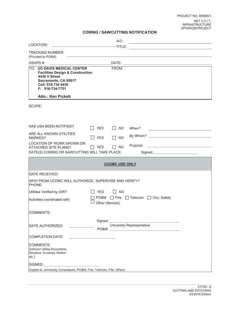
01730 - 5CUTTING AND PATCHING
03/2016 Edition
PROJECT NO. 9559401NET V.2 I.T.
INFRASTRUCTURE UPGRADEPROJECT
CORING / SAWCUTTING NOTIFICATION
A/C: LOCATION: TITLE:TRACKING NUMBER:(Provided by PO&M)
OSHPD #: DATE: TO: UC DAVIS MEDICAL CENTER FROM:
Facilities Design & Construction 4430 V StreetSacramento, CA 95817Cell: 916.734 4436F: 916-734-7751
Attn.: Ken Pickett
SCOPE:
HAS USA BEEN NOTIFIED? When?
By Whom?
Purpose:
DATE(S) CORING OR SAWCUTTING WILL TAKE PLACE: Signed:
UCDMC USE ONLY
DATE RECEIVED:
WHO FROM UCDMC WILL AUTHORIZE, SUPERVISE AND VERIFY? PHONE:
Utilities Verified by IOR? YES NO
Activities coordinated with: PO&M Fire Telecom Occ. SafetyOther (Itemize):
COMMENTS:
Signed: DATE AUTHORIZED: University Representative
PO&M:
COMPLETION DATE:
COMMENTS:(Unknown Utilities Encountered, Disruptions, Successes, Weather, etc.)
SIGNED: Copies to: University Consultants, PO&M, Fire, Telecom, File, Others:
YES NOARE ALL KNOWN UTILITIES MARKED? YES NOLOCATION OF WORK SHOWN ON ATTACHED SITE PLANS? YES NO

01740 - 6CLEANING
03/2016 Edition
PROJECT NO.9559410NET V.2 IT Infrastructure Upgrade in the UC DAVIS Comprehensive Cancer Center.
SECTION 01740 CLEANING
PART I - GENERAL
1.01 SECTION INCLUDES
A. Construction Cleaning.
B. Requirements for cleaning during progress of Work, at Substantial Completion of Work and at Acceptance of Work.
C. Disposal of waste materials, debris and rubbish during construction.
1.02 RELATED SECTIONS
A. General Conditions of the Contract: Cleanup.
B. Additional Requirements: Cleaning for specific products or elements of Work are described in Specification Sections describing that Work.
PART II - PRODUCTS
2.01 MATERIALS
A. Use only those cleaning agents and materials that will not create hazards to health or property and that will not damage surfaces.
B. Use only those cleaning agents, materials and methods recommended by manufacturer of the material to be cleaned.
C. Use cleaning materials only on surfaces recommended by cleaning agent manufacturer.
2.02 EQUIPMENT
A. Provide covered containers for deposit of waste materials, debris, and rubbish.
B. Provide at each entry point to the Work, and at other areas as directed by University's Representative, Dryden Engineering, "Micro-Clean Adhesive Mat, #TS/1847", or equal (no known equal). Replace mats daily or as requested by University Representative.
PART III - EXECUTION
3.01 CLEANING
A. Construction Cleaning: During Construction, maintain buildings, premises and property free from waste materials and rubbish. Dispose of such waste and debris at reasonable intervals off of University property.
1. Maintain areas under Contractor's control free of waste materials, debris and rubbish. Maintain site in a clean and orderly condition.

01730 - 7CUTTING AND PATCHING
03/2016 Edition
PROJECT NO.9559410NET V.2 IT Infrastructure Upgrade in the UC DAVIS Comprehensive Cancer Center.
2. Remove debris and rubbish from pipe chases, plenums, attics, crawl spaces, and other closed or remote spaces, prior to closing such spaces.
3. Clean interior areas daily to provide suitable conditions for Work. Remove debris from areas of work on a daily basis at a minimum, or more often as required to provide suitable conditions for work.
4. Broom clean interior areas prior to start of surface finishing, and continue cleaning on as needed basis.
5. Control cleaning operations so that dust and other particles will not adhere to wet or newly-coated surfaces.
6. Provide a mat, as specified above, for project entrances and exits. Item to be of sufficient size to allow personnel exiting project site to clean debris and dust from shoes. Tracking dust and debris through working areas of hospital and/or related buildings is not acceptable. Any dust or debris tracked out of construction site,
either by foot traffic or by debris hauling vehicles, at University option, shall be cleaned and removed by Contractor at no additional cost to the University.
B. Conduct cleaning and disposal operations in compliance with all applicable codes, ordinances, regulations, including anti-pollution laws.
3.02 SUBSTANTIAL COMPLETION CLEANING
A. Execute a thorough cleaning prior to Substantial Completion review by University's Representative.
B. Clean walkways, driveways and streets by thorough brooming and wash-down.
C. Clear debris from storm drainage lines and ways, leaving site ready for stormy weather.
D. Rake landscaped areas clean.
E. Remove waste and surplus materials, rubbish and temporary construction facilities, utilities and controls.
F. Disinfect containment and protection areas as directed by University Representative.
G. For Airborne Contamination areas: Construction cleaning use wet cleaning methods and HEPA-filtered vacuum cleaners are required to minimize release of airborne contaminants. Contain waste materials, debris and rubbish.
3.03 FINAL COMPLETION CLEANING
A. Complete final cleaning before submitting final Application for Payment.
B. Employ professional building cleaners to thoroughly clean building immediately prior to final inspection.
C. Remove grease, mastic, adhesives, dust, dirt, stains, fingerprints, labels, and other foreign materials from all sight-exposed interior and exterior surfaces.
D. Restore damaged or marred surfaces.
E. Remove dust from all horizontal surfaces not exposed to view, including light fixtures, ledges and fixture lenses.

01740 - 8CLEANING
03/2016 Edition
PROJECT NO.9559410NET V.2 IT Infrastructure Upgrade in the UC DAVIS Comprehensive Cancer Center.
F. Clean and polish all glass, mirrors, and bright metal work. Clean and disinfect all plumbing fixtures.
G. Damp wash all resilient flooring. Waxing of resilient flooring shall be done by the University.
H. Thoroughly sweep all floors and vacuum all carpets. Cleaning of Work provided by University under separate contracts, will not be required except if soiled by construction activities under this Contract.
I. Thoroughly clean and polish all resilient flooring, metal and plastic surfaces; remove labels and protective coatings.
J. Replace filters and clean heating and ventilating equipment used for temporary heat and ventilation.
01740 - 3CLEANING

PROJECT NO.9559410NET V.2 IT Infrastructure Upgrade in the UC DAVIS Comprehensive Cancer Center.
03/2016 Edition
K. Remove waste material or equipment that has been damaged, touch up and /or repair exposed areas; such repairs to be approved by University's Representative.
L. Should final cleaning be inadequate, as determined by University's Representative, and Contractor fails to correct conditions, University's Representative may order thorough cleaning and deduct the cost from Final Payment.
3.04 FINAL COMPLETION SITE CLEANING
A. Broom clean exterior paved surfaces. Rake clean other surfaces of the grounds.
B. Hose down and scrub where necessary all concrete and walks dirtied as a result of the construction work. Thoroughly remove mortar droppings from all walks and pavements.
C. Remove from the site all tools, equipment, construction waste, unused materials, excess earth, and all debris resulting from the Work.
3.05 DISPOSAL
A. Conduct cleaning and disposal operations in compliance with all applicable codes, ordinances, regulations, including anti-pollution laws.
B. Do not bury or burn rubbish or waste material on University premises.
C. Do not dispose of volatile wastes, such as mineral spirits, oil, or paint thinner, in storm or sanitary drains.
D. Remove waste materials, debris, and rubbish from site and dispose of off-site.
3.06 INSPECTION
A. Prior to final completion or University use of premises, Contractor and University's Representative shall jointly conduct an inspection of sight-exposed interior and exterior surfaces to verify that entire Work is clean.
END OF SECTION 01740
01740 - 4CLEANING

03/2016 Edition
PROJECT NO.9559410NET V.2 IT Infrastructure Upgrade in the UC DAVIS Comprehensive Cancer Center.
SECTION 01750STARTING AND ADJUSTING SYSTEMS
PART I - GENERAL
1.01 SECTION INCLUDES
A. Procedures for Starting Systems
1.02 REALATED SECTIONS
A. Section 01810 – PLUMBING/HVAC TESTING PROCEDURES
B. Section 01820 – DEMONSTRATION AND TRAINING
1.03 SUBMITTAL REQUIREMENTS
A. Submit preliminary schedule listing times and dates for start-up of each item of equipment in sequence in writing, minimum of fourteen (14) calendar days prior to any start-up.
B. Submit manufacturer's representative reports within one (1) week after start-up, listing satisfactory start-up dates.
1.04 PROJECT CONDITIONS
A. Building enclosure shall be complete and weather-tight.
B. Excess packing and shipping bolts shall be removed.
C. Interdependent systems shall have been checked and made operational.
PART II - PRODUCTS – Not Applicable to this Section
PART III - EXECUTION
3.01 INSPECTION
A. Verify Project conditions comply with requirements for start-up.
B. Verify status of Work meets requirements for starting equipment and systems.
3.02 PREPARATION
A. Coordination: Coordinate sequence for start-up of various item of equipment.
B. Notification: Notify University in writing, minimum of fourteen (14) calendar days prior to start-up of each item of equipment.
C. Information on hand: Have Contract Documents, shop drawings, product data, and operation and maintenance data at hand during entire start-up process.
D. Verify each piece of equipment has been checked for proper lubrication, drive rotation, belt tension, control sequence, and other conditions that may cause damage.
01750 - 1STARTING AND ADJUSTING SYSTEMS

PROJECT NO.9559410NET V.2 IT Infrastructure Upgrade in the UC DAVIS Comprehensive Cancer Center.
01760 - 1PROTECTING INSTALLED CONSTRUCTION
03/2016 Edition
E. Verify control systems are fully operational in automatic mode.
F. Manufacturer's Criteria: Verify tests, meter readings and specific electrical characteristics agree with electrical equipment manufacturers' criteria.
G. Bearings: Inspect for cleanliness: clean and remove foreign matter, verify alignment. Take corrective action as required.
H. Drives: Inspect for tension on belt drives, adjustment of vari-pitch sheaves and drives, alignment, proper equipment speed, and cleanliness. Take corrective action as required.
I. Motors: Verify motor amperage agrees with nameplate value. Inspect for conditions that produce excessive current flow and that exist due to equipment malfunction. Take corrective action as required.
3.03 STARTING SYSTEMS
A. Execute start-up under supervision of responsible Contractor personnel.
B. Place equipment in operation in proper sequence in accordance with sequencing schedule.
END OF SECTION 01750
01750 - 2STARTING AND ADJUSTING SYSTEMS

03/2016 Edition
PROJECT NO.9559410NET V.2 IT Infrastructure Upgrade in the UC DAVIS Comprehensive Cancer Center.
SECTION 01760 PROTECTING INSTALLED CONSTRUCTION
PART I - GENERAL
1.01 SECTION INCLUDES
A. Protection for Products Including University Provided Products, After Installation.
B. Protection of Existing Utilities and Interference.
1.02 RELATED SECTIONS
A. Section 01310 – COORDINATION
B. Section 01510 – TEMPORARY UTILITIES
1.03 EXISTING UTILITIES
A. Known Utilities: Known existing utilities are shown on Contract Drawings in approximate locations. Contractor shall exercise care in avoiding damage to existing facilities. Contractor shall be responsible for repair of same if damaged through Contractor's action. Hand excavation shall be utilized when digging in close proximity to existing utilities. University does not guarantee that all utilities or obstructions are shown, or that locations indicated are accurate.
B. Electrical Equipment: No work shall be performed on energized electrical equipment unless scheduled with University's Representative. University reserves right to specify specific conditions for all work involving energized high voltage electrical equipment and its scheduled modification proposal.
C. Uncovering Facilities: Prior to any earthwork for new construction, Contractor shall uncover all existing piping where crossings, interferences or connections are shown on Contract Drawings, from one (1) foot below proposed construction limit to the existing ground surface. Any variation in actual elevations and indicated elevations shall be brought to University's Representative attention. If Contractor does not expose all existing utilities, Contractor shall not be entitled to additional compensation for work necessary to avoid unknown interferences.
D. Interferences: If interferences occur at locations other than general locations shown on Contract Drawings, and such utilities are damaged before such locations have been established, or create an interference, Contractor shall immediately notify University's Representative and a method for correcting said interference shall be supplied by University. Payment for additional work due to interferences not shown on Contract Drawings shall be in accordance with the General Conditions of the Contract. Cost of repair to damaged utilities shall be deducted from the Contract Sum.
E. Accuracy of Drawings: Drawings showing location of equipment, piping, etc. are diagrammatic and job conditions will not always permit installations in locations shown. When a conflict situation occurs, immediately bring to attention of University's Representative for determination of relocation.

01760 - 1PROTECTING INSTALLED CONSTRUCTION
03/2016 Edition
PROJECT NO.9559410NET V.2 IT Infrastructure Upgrade in the UC DAVIS Comprehensive Cancer Center.
F. Deviations from Drawings: Information shown relative to existing power and signal service is based upon available records and data but shall be regarded as approximate only. Minor deviations found necessary to conform with actual locations and conditions shall be made at no change to the Contract Sum.
PART II - PRODUCTS – Not Applicable to this Section
PART III - EXECUTION
3.01 PROTECTION AFTER INSTALLATION
A. Installed Equipment and Materials: Adequately protect all installed equipment and materials until completion and acceptance by University's Representative.
B. Existing Facilities: All existing improvements and facilities shall be protected from damage of any type resulting from operations, equipment or workers of Contractor during the construction process.
C. Subsequent Operations: Protect installed products and control traffic in immediate area to prevent damage from subsequent operations.
D. Traffic Areas: Provide protective coverings at walls, projections, corners, and jambs, sills, and soffits of openings in and adjacent to traffic areas.
E. Elevators: Cover walls and floors of elevator cabs, and jambs of cab doors, when elevators are used by construction personnel.
F. Finished Floors: Protect finished floors and stairs from dirt, wear, and damage:
1. Secure heavy sheet goods or similar protective materials in place, in areas subject to foot traffic.
2. Lay planking or similar rigid materials in place in areas subject to movement of heavy objects and where storage of products will occur.
G. Waterproofed and Roofed Surfaces:
1. Restrict use of surfaces for traffic of any kind, and for storage of products.
2. When an activity is mandatory, obtain recommendations for protection of surfaces from manufacturer. Install protection and remove on completion of activity. Restrict use of adjacent unprotected areas.
H. Lawns and Landscaping: Restrict traffic of any kind across planted lawn and landscaped areas.
I. Adjacent Facilities: Care shall be exercised to prevent damage to adjacent facilities including walks, curbs, and gutters. Planking shall be placed where equipment will pass over such obstructions, and facilities damaged by construction operations shall be removed and replaced at Contractor's expense.
01760 - 2PROTECTING INSTALLED CONSTRUCTION

03/2016 Edition
PROJECT NO.9559410NET V.2 IT Infrastructure Upgrade in the UC DAVIS Comprehensive Cancer Center.
J. Overloading: Contractor shall be responsible for overloading any part or parts of structures beyond the calculated capacities of the design. Placing materials, equipment, tools, machinery or any other item shall be done with care to avoid overloading. No loads shall be placed on floors or roofs before they have attained their permanent and safe strength.
K. Damaged Work: All damaged work shall be replaced, repaired and restored to its original condition without change to the Contract Sum. Repair or replace all damaged work promptly as directed by University's Representative.
L. Damaged Utilities: Where existing utilities are damaged or disrupted on account of any act, omission, neglect or misconduct of the Contractor in the manner or method of executing the Work, or due to non-execution of work, such damage shall be immediately repaired to maintain operation regardless of the time of occurrence.
M. Temporary Construction: Provide temporary construction necessary for protection of building and its parts. Close in buildings as soon as possible to protect from weather and vandalism. Protect existing buildings and controlled temperature areas from damage.
N. Doors and Casework: Protect doors, millwork and mill counters and cases and hardware from damage, including abrading and scratching of finishes. Protect doors and frames and hardware from mechanical damage and damage to anodic coatings.
O. Protective Coatings: Remove protective coatings, etc., as required to leave work in condition for painting and finishing, final cleaning, etc.
P. Exterior Work: Protect all exterior work, including existing asphalt paving and landscaping and buildings.
END OF SECTION 01760

PROJECT NO.9559410NET V.2 IT Infrastructure Upgrade in the UC DAVIS Comprehensive Cancer Center.
01770 - 1CLOSEOUT PROCEDURES
03/2016 Edition
SECTION 01770 CLOSEOUT PROCEDURES
PART I - GENERAL
1.01 SECTION INCLUDES
A. Project Closeout Procedures
B. Contract Closeout Procedures
1.02 RELATED SECTIONS
A. Section 01310 – COORDINATION
B. Section 01330 – SHOP DRAWINGS, PRODUCT DATA AND SAMPLES: Administrative general requirements for submittals.
C. Section 01560 – TEMPORARY BARRIERS, ENCLOSURES AND CONTROLS: Removal of Controls.
D. Section 01740 – CLEANING: Final Cleaning.
E. Section 01780 – CLOSEOUT SUBMITTALS
1.03 FINAL COMPLETION ACTIONS
A. On Application for Payment that coincides with date Substantial Completion is claimed, show 100% completion for portion of Work claimed substantially complete.
B. Submit specific warranties, workmanship bonds, maintenance agreements, final certifications and similar documents.
C. Change building locks from construction to permanent keying, as directed by University's Representative.
D. Complete start-up testing of systems, and instruction of University personnel. Remove temporary facilities from site, along with construction tools, mock-ups, and similar elements.
1.04 SUBSTANTIAL COMPLETION REVIEW
A. Preliminary Punch List Review: At Contractor's request, University's Representative will attend preliminary contract closeout review, not later than fourteen (14) calendar days prior to anticipated Substantial Completion review date.
1. Contractor shall provide at preliminary review a typewritten list (Preliminary Punch List) of items to be completed and corrected.
2. List shall identify items by location (e.g., room number and name) and consecutive number (e.g., 307-5 might identify item 5 in room 307, Roof-4 would identify item 4 on Roof).

PROJECT NO.9559410NET V.2 IT Infrastructure Upgrade in the UC DAVIS Comprehensive Cancer Center.
03/2016 Edition
3. Segregate architectural, plumbing, HVAC and electrical Work on separate lists.
4. University's Representative and Contractor shall conduct a brief walk-through of Project to review scope and adequacy of list.
B. Contractor's Certification: When determined by Contractor that Work is substantially complete, Contractor shall notify University's Consultant and University's Representative.
1. Submit to University's Representative written certification that:
a. Contract Documents have been reviewed.
b. All portions of Work have been carefully inspected.
c. Work is complete in accordance with Contract Documents.
d. Equipment and systems have been tested, adjusted and balanced and are fully operational.
e. Operation of systems has been demonstrated to University personnel.
f. Work is ready for University's Consultant's Substantial Completion review.
2. Provide minimum seven (7) working days notice to University's Representative prior to desired date for Punch List review.
C. Punch List Review: University's Representative and University's Consultants as may be required, will attend a Contract closeout review and conduct a walk-through of Project toreview Contractor's list of items to be completed and corrected (Punch List). Contractor and University's Consultant shall note deficiencies, if any.
1. Contractor shall prepare list and record additional items as University's Representative may determine require completion and correction from walk- through.
a. If deficiencies are noted University's Representative and University's Consultant shall promptly notify Contractor in writing, listing observed deficiencies.
b. If no deficiencies are noted, or when noted deficiencies are removed from the Punch List, University's Representative shall promptly notify Contractor.
2. Contractor shall re-type and distribute list with University's Representative and University's Consultant's additions.
3. Contractor shall remedy deficiencies.
4. Costs of additional visits to site by University's Consultants to review completion and correction of Work shall be deducted from the Contract Sum.
D. Uncorrected Work: Refer to requirements specified in SECTION 01450 – QUALITY CONTROL regarding Contract adjustments for non-conforming work.
E. Cleaning and Clearing: Prior to Substantial Completion review, execute cleaning and clearing site of temporary facilities and controls, as specified in SECTION 01560 – TEMPORARY BARRIERS, ENCLOSURES AND CONTROLS.
PROJECT NO.9559410NET V.2 IT Infrastructure Upgrade in the UC DAVIS Comprehensive Cancer Center.
03/2016 Edition
F. Testing and Inspection: Prior to Substantial Completion review, complete all tests and inspections and submit applicable reports and approvals.
1. Complete materials tests and inspections.
2. Complete testing, inspection, balancing, sterilization and cleaning of plumbing and HVAC systems.
3. Complete testing and inspection of electrical system.
4. Complete operational tests of equipment.
G. Consultant's Certification: University's Consultant will complete and issue notice of Substantial Completion on American Institute of Architect's Form G704 – CERTIFICATE OF SUBSTANTIAL COMPLETION.
1. Certificate will be completed when University's Consultant determines that list of items to be completed and corrected (Punch List) are sufficiently complete for University to occupy Project for the use intended.
2. University's Consultant will forward copies of completion certification to University and Contractor.
3. IF OSHPD PROJECT: Submit two (2) originals of Contractor's Final OSHPD Verified Reports to University's Representative certifying completion of the Workin conformance with the Contract Documents. Report forms will be supplied by University's Representative.
H. Acceptance of the Work shall not relieve Contractor of any responsibility for defects that develop during the guarantee period and are caused by Contractor's failure to perform work in accordance with requirements of Contract Documents.
1.05 FINAL COMPLETION SUBMITALS
A. Evidence of Compliance with Requirements of Governing Authorities:
1. Certificate of Occupancy.
2. Compliance Notification: In conformance with State of California Energy Conservation Standards, Contractor shall, at time of request for final inspection, issue to University's Representative notarized certificate stating completed work appears, in every material respect, to be in compliance with approved Contract Documents. Provide only if specifically required.
B. Final Specifications Submittals: Submit to University's Consultant all documents and products required by Specifications to be submitted, including the Following:
1. Project Record Drawings: Submit under provision of SECTION 01780 – CLOSEOUT SUBMITTALS.
2. Operation and Maintenance Data: Submit under provision of SECTION 01780 – CLOSEOUT SUBMITTALS.
3. Guarantees, Warranties, Bonds, Service and Maintenance Contracts: Submit under provision of SECTION 01780 – CLOSEOUT SUBMITTALS.
4. Spare Parts and Maintenance Materials: Submit under provision of SECTION 01780 – CLOSEOUT SUBMITTALS.

PROJECT NO.9559410NET V.2 IT Infrastructure Upgrade in the UC DAVIS Comprehensive Cancer Center.
03/2016 Edition
5. Keys and Keying Schedule: At completion of Project, all keys shall be returned to University's Representative. Failure to return a key will obligate Contractor for all costs of re-keying facility.
C. Certificates of Compliance and test Report Submittals: Submit to University's Representative certificates and reports as specified and required, including the following:
1. Sterilization of water system
2. Sanitary sewer system tests
3. Gas system tests
4. Lighting, power and signal system tests
5. HVAC equipment and air balance tests
D. Lien and Bonding Company Releases: Submit to University's Representative, copies of all conditional and unconditional general/subcontractor lien releases showing satisfaction ofencumbrances and release of liens of Project by completion and submission of Exhibits of the General Conditions of the Contract, as applicable. Signatures shall be notarized.
E. Subcontractor's List: Submit to University's Representative five (5) copies of updated Subcontractor and Materials Supplier List.
F. Warranty Documents: Prepare and submit to University's Representative all warranties and bonds as specified in SECTION 01780 – CLOSEOUT SUBMITTALS.
1.06 STATEMENT OF ADJUSTMENT OF ACCOUNTS
A. Submit final statement reflecting adjustments to Contract Sum indicating:
1. Original Contract Sum
2. Previous Change Orders
3. Changes under allowances
4. Changes under unit prices
5. Deductions for uncorrected work
6. Penalties
7. Deductions for liquidated damages
8. Deductions for re-inspection fees
9. Other adjustments to Contract Sum
10. Total Contract Sum as adjusted
11. Previous payments
12. Sum remaining due
B. University will issue a final Change Order reflecting approved adjustments to Contract Sum not previously made by Change Order.

PROJECT NO.9559410NET V.2 IT Infrastructure Upgrade in the UC DAVIS Comprehensive Cancer Center.
03/2016 Edition
1.07 APPLICATION FOR FINAL PAYMENT
A. Final Payment: After completion of all items listed for completion and correction, after submission of all documents and products, and after final cleaning, submit final Application for Payment, identifying total adjusted Contract Sum, previous payments and sumremaining due. Refer to SECTION 01290 – MEASUREMENT AND PAYMENT and the General Conditions of the Contract.
B. Submit Record Documents to University's Representative with final Application for Payment.
1.08 PROJECT AS-BUILT DOCUMENTS
A. Maintain on site, one (1) set of the following as-built documents and record actual construction and all revisions to the Work:
1. Contract Drawings
2. Contract, with Specifications, Addenda, Change Orders, and modifications to the Contract.
3. Approved shop drawings, product data and samples.
4. Store As-built Documents separate from documents used for construction.
B. Drawings: Record information continuously as Work progresses. Do not conceal Work permanently until required information is recorded.
C. Specifications: In PART 2 – PRODUCTS in each Section, legibly mark and record actual Products installed or used, including:
1. Manufacturer, trade name, product model or catalog number and supplier of each product or item of equipment installed.
2. Product substitutions or alterations utilized.
3. Changes made by Addenda, Modification, Change Order, Field Order, and clarifications or interpretations made by Letter of Instruction.
D. As-built Drawings: Keep up to date during entire progress of the Work and make available to University at any time. Recording of the As-built condition shall be carefully and neatly done by a competent drafter, familiar with the trade involved, using methods acceptable to University's Representative. Legibly and to scale, mark a reproducible set of Contract Drawings to record all changes in size, location, and other features of installation in the actual construction, including:
1. Measured depths of foundations and footings encountered, measured in relationship to finish First Floor datum.
2. Measured horizontal and vertical locations of underground utilities and appurtenances referenced to permanent ground improvements.
a. Locations of work buried under or outside building footprint, such as plumbing and electrical lines and conduits.
b. Record all locations of underground work, points of connection, valve locations, manholes, catch basins, capped stub-outs, invert elevations, etc.

PROJECT NO.9559410NET V.2 IT Infrastructure Upgrade in the UC DAVIS Comprehensive Cancer Center.
03/2016 Edition
3. Field changes of dimension and detail.
a. Locations of all significant work concealed inside building, the locations of which are changed by Contractor from those shown on Contract Drawings.
b. Locations of all items, not necessarily concealed, which vary from locations shown on the Contract Drawings.
c. Record sufficient information so that concealed work may be located with reasonable ease and accuracy.
4. Actual numbering of each electrical circuit.
5. Details not on original Contract Drawings.
6. Additional drawings as required to properly describe changes.
7. Reproducible set of Contract Drawings will be provided to Contractor by University's Representative.
E. Shop Drawings: Provide reproducible Record copy, made from final Shop Drawings, updated to show actual conditions for work specified in individual Sections.
F. Large Scale Drawings: Divisions 15 and 16 of the Contract Specifications require preparation of large-scale, detailed layout drawings for the work of those Divisions. These layout drawings are not shop drawings as defined by the General Conditions of the Contract but together with Shop Drawings or layout drawings of all other affected sections, are used to check, coordinate and integrate the Work of the Various Sections. Maintain and submit these layout drawings as part of the Project Record Drawings.
G. Acceptance: All Record Documents are subject to review and acceptance by University.PART II - PRODUCTS – Not Applicable to this Section
PART III - EXECUTION – Not Applicable to this Section
END OF SECTION 01770

PROJECT NO.9559410NET V.2 IT Infrastructure Upgrade in the UC DAVIS Comprehensive Cancer Center.
01780 - 1CLOSEOUT SUBMITTALS
03/2016 Edition
SECTION 01780 CLOSEOUT SUBMITTALS
PART I - GENERAL
1.01 SECTION INCLUDES
A. Equipment Data
B. Operation and Maintenance Instructions
C. Instruction of UCDMC personnel
D. Schedule of Submittals
E. Spare Parts and Maintenance Materials
F. Guarantees, Warranties, Bonds, Service and Maintenance Contracts
G. Project As-built Documents
1.02 RELATED SECTIONS
A. Section 01310 – COORDINATION
B. Section 01330 – SHOP DRAWINGS, PRODUCT DATA AND SAMPLES
C. Administrative general requirements for submittals.
D. Section 01450 – QUALITY CONTROL: Manufacturer's tests and inspections as a condition of warranty.
E. Section 01610 – PRODUCT REQUIREMENTS
F. Section 01770 – CLOSEOUT PROCEDURES
1.03 EQUIPMENT DATA AND OPERATION AND MAINTENANCE INSTRUCTIONS
A. Preparation of data shall be done by persons:
1. Trained and experienced in maintenance and operation of described products.
2. Familiar with requirements of this Section.
3. Skilled in technical writing to extent required for communication of essential data.
4. Skilled as drafters competent to prepare required drawings
B. Equipment Manual Format: Prepare in the form of a data and instructional manual.

PROJECT NO.9559410NET V.2 IT Infrastructure Upgrade in the UC DAVIS Comprehensive Cancer Center.
01780 - 2CLOSEOUT SUBMITTALS03/2016 Edition
1. Binders: Commercial quality, 8-½” x 11", three-ring binders with hardback, cleanable, plastic covers; 1" minimum, 1-½” maximum ring size. Provide separate binders, submitted separately for each discipline, i.e. Site Work, Doors and Windows, Conveying Systems, Mechanical, Plumbing, Electrical, etc. Correlate data into related consistent groupings. Provide two (2) copies of data in Adobe PDF format on CD as well.
2. Cover: Identify each binder with typed or printed title "EQUIPMENT DATA AND OPERATION AND MAINTENANCE INSTRUCTIONS".
a. List Project title and Project number and particular building as applicable.
b. Identify contents.
3. Organization: Arrange content by systems under Section numbers and sequence in accordance with the Project Specifications Table of Contents. Provide tabbed flyleaf for each separate product and system with typed description of product and major component parts of equipment.
4. Text: Manufacturer's printed data or typewritten data on 20 pound paper.
5. Drawings: Provide with reinforced punched binder tabs. Bind in with text; fold larger drawings to size of text page. Do not hole punch drawings. Insert drawings in clear plastic holder.
C. Table of Contents, Each Volume: Provide title of Project, Project number, with names, addresses, and telephone numbers of University's Representative, as applicable, and Contractor, including name of contact person. Provide schedule of products and systems, indexed to content of the volume.
1. For each Product or System: List names addresses and telephone numbers of subcontractor, original supplier and manufacturer, as applicable, including name
of contact person. Include name and address of local source of supplies and replacement parts.
2. Product Data: Mark each sheet to clearly identify specific products and component parts, and data applicable to installation. Delete information not applicable.
3. Drawings: Supplement product data to illustrate relations of component parts of equipment and systems, to show control and flow diagrams. Do not use Project Record Documents as maintenance drawings.
4. Additional Text: As required to supplement product data. Provide logical sequence of instructions for each procedure, incorporating manufacturer's instructions specified in SECTION 01450 – QUALITY CONTROL.
5. Warranties and Bonds: Bind in copy of each.
D. Manual for Materials and Finishes:
1. Building Products, applied Materials, and Finishes: Include product data, with catalog number, size, composition, and color and texture designations. Provide information for re-ordering custom manufactured Products.

PROJECT NO.9559410NET V.2 IT Infrastructure Upgrade in the UC DAVIS Comprehensive Cancer Center.
01780 - 3CLOSEOUT SUBMITTALS
03/2016 Edition
2. Instruction for Care and Maintenance: Include manufacturer's recommendations for cleaning agents and methods, precautions against detrimental agents and methods, and recommended schedule for cleaning and maintenance.
3. Moisture Protection and Weather Exposed Products: Include product data listing applicable reference standards, chemical composition, and details of installation. Provide recommendations for inspections, maintenance, and repair.
4. Additional Requirements: As specified in individual Specification Sections.
5. Table of Contents: Provide a listing in Table of Contents for design data, with tabbed binder divider page and space for insertion of data.
E. Manual For Equipment And Systems
1. Record Instructions: Forward to University's Representative, upon completion of work, and before work will be considered for acceptance, complete bound sets of instructions of entire plant and component parts, including manufacturer's certificates, warranty slips, parts lists, descriptive brochures, and maintenance and operating instructions, in quantities set forth in various Divisions. Print information on heavy white paper, tab properly and identify for each reference. Submit drafts for review before preparing final sets, six (6) copies required.
2. O & M Instructions: Provide and install, where directed, printed sheet under clear plastic cover, giving concise operating and maintenance instruction for equipment.
3. Each Item of Equipment and Each System: Inclusive description of unit or system, Model Number, Serial Number, and component parts. Identify function, normal characteristics, and limiting conditions. Include performance curves, with engineering data and tests, and complete nomenclature and commercial number of replaceable parts. Best to include all information provided in final approvedequipment submittal. Design drawing data may not reflect what was actually provided.
4. Panelboard Circuit Directories: Provide electrical service characteristics, controls and communications.
5. Wiring Diagrams: Include color-coded wiring diagrams as installed.
6. Operating Procedures: Include start-up, break-in, and routine normal operating instructions and sequences. Include regulation, control, stopping, shutdown, and emergency instructions. Include summer, winter, and any special operating instructions.
7. Maintenance Requirements: Include routine procedures and guide for trouble- shooting; disassembly, repair, and re-assembly instructions; and alignment, adjusting, balancing, and checking instructions. Provide servicing and lubrication schedules, and list of lubricants required.
8. Instructions: Include manufacturer's printed operation and maintenance instructions. Include sequence of operation by controls manufacturer.

PROJECT NO.9559410NET V.2 IT Infrastructure Upgrade in the UC DAVIS Comprehensive Cancer Center.
01780 - 4CLOSEOUT SUBMITTALS03/2016 Edition
9. Parts Data: Provide original manufacturer's parts list, illustrations, assembly drawings, and diagrams required for maintenance. Provide list of original manufacturer's spare parts, current prices, and recommended quantities to be maintained in storage.
10. Control Data: Provide as installed control diagrams by controls manufacturer.
11. Piping Data: Provide Contractor's coordination drawings, with color piping diagrams as installed. Provide charts of valve tag numbers, with location and function of each valve, keyed to flow and control diagrams.
12. Design Data: Provide a listing in table of Contents for design data, with tabbed binder divider page and space for insertion of data.
13. Reports: Include test and balancing reports as specified in SECTION 01810 – TESTING, ADJUSTING AND BALANCING PROCEDURES.
14. Additional Requirements: As specified in individual Specification Sections.
F. Instruction of University's Personnel: Instruct University designated personnel to their full and complete understanding, procedures necessary to operate and maintain equipment and systems on continuing basis. Provide training of staff.
1. Schedule: Before final inspection, instruct University designated personnel in operation, adjustment, and maintenance of products, equipment, and systems, at agreed upon times. For equipment requiring seasonal operation, perform instructions for other seasons within six (6) months of completion.
2. Basis of Information: Use operation and maintenance manuals as basis for instruction. Review contents of manual with personnel in detail to explain all aspects of operation and maintenance.
3. Instructional Material: Prepare and insert additional data in the manual when need for such data becomes apparent during instruction.
G. Equipment Data and Operation and Maintenance Instructions Submittals:
1. Submittals: Comply with administrative requirements specified in SECTION 01330– SHOP DRAWINGS, PRODUCT DATA AND SAMPLES.
2. Preliminary Draft Submittal: Submit two (2) copies of preliminary draft or proposed formats and outlines of contents no later than ten (10) days of equipment submittals approval. University's Representative will review draft and return one(1) copy with comments.
3. Advance Submittals: For equipment, or component parts of equipment to be put into service during construction and operated by University, submit documents within ten (10) calendar days after equipment approval.
4. Final Submittal: After completion of instruction of University operation and maintenance personnel and final inspection, revise content of documents to include additional information deemed necessary from instruction experience of University's personnel and any changes made during construction. Submit three(3) copies of completed volumes in final form a minimum of ten (10) calendar days after final inspection.

PROJECT NO.9559410NET V.2 IT Infrastructure Upgrade in the UC DAVIS Comprehensive Cancer Center.
01780 - 5CLOSEOUT SUBMITTALS
03/2016 Edition
1.04 SPARE PARTS AND MAINTENANCE MATERIALS
A. Products Required: Where called for in Contract Specifications, deliver to University's Representative, materials, etc., for use in maintenance work. Provide list of materials delivered to University's Representative, indicating date and acceptance by University's Representative.
1. Provide quantities of products, spare parts, maintenance tools, and maintenance materials specified in individual Sections to be provided to University's Representative, in addition to that required for completion of the Work.
2. Products supplied shall be identical to those installed in the Work. Include quantities in original purchase from supplier to avoid variations in manufacture.
B. Storage, maintenance: Store products with products to be installed in the Work, as specified in SECTION 01610 – PRODUCT REQUIREMENTS: Product Storage and Protection.
C. Delivery to site: Prior to final payment, deliver and unload spare products to project site. Coordinate with University's Representative and obtain receipt. University will handle and store products.
1.05 WARRANTIES AND GUARANTEES
A. Warranties and Guarantees, general: Guarantees from subcontractors shall not limit Contractor's warranties and guarantees. Whenever possible, Contractor shall cause warranties of subcontractors to be made directly to University. If such warranties are made to Contractor, Contractor shall assign such warranties to University prior to final payment. When equipment and products, or components thereof, bear a manufacturer's warranty orguarantee that extends the time period of Contractor's warranty or guarantee, so state in the warranty or guarantee.
1. Standard Product Warranties: Preprinted written warranties published by individual manufacturers for particular products and specifically endorsed by manufacturer to University.
2. Special Warranties: Written warranties required by or incorporated in Contract Documents, to extend time limits provided by standard warranties or to provide greater rights for University.
3. Provisions for Special Warranties: Refer to General Conditions of the Contract for terms of Contractor's special warranty of workmanship and materials.
4. Specific Warranty Requirements: requirements are included in the individual Sections of Division 2 through 16 of the Contract Specifications, including content and limitations
5. Disclaimers and Limitations: Manufacturer's disclaimers and limitations on product warranties do not relieve Contractor of warranty on work that incorporates the products, nor does it relieve suppliers, manufacturers, and subcontractors requirement to countersign special warranties with Contractor.
6. Related Damages and Losses: When correcting warranted work that has failed, remove and replace other work that has been damaged as a result of such failure or that must be removed and replaced to provide access for correction of warranted work.

PROJECT NO.9559410NET V.2 IT Infrastructure Upgrade in the UC DAVIS Comprehensive Cancer Center.
01780 - 6CLOSEOUT SUBMITTALS03/2016 Edition
7. Reinstatement of Warranty: When work covered by a warranty has failed and been corrected, reinstate the warranty by written endorsement. The reinstated warranty shall be equal to original warranty with an equitable adjustment for depreciation.
8. Replacement Cost: On determination that work covered by a warranty has failed, replace or rebuild the work to an acceptable condition complying with requirements of Contract Documents. Contractor shall be responsible for cost of replacing or rebuilding defective work regardless of whether University has benefited from use of the work through part of its useful service life.
9. UCDMC Recourse: Written warranties made to University are in addition to implied warranties, and shall not limit duties, obligations, right and remedies otherwise available under the law, nor shall warranty periods be interpreted as limitations on time in which University can enforce such other duties, obligations, rights, or remedies.
10. Rejection of Warranties: University reserves right to reject warranties and to limit selections to products with warranties not in conflict with requirements of the Contract Documents.
11. University reserves right to refuse to accept work where a special warranty, or similar commitment is required, until evidence is presented that entities required to countersign commitments are willing to do so.
12. When designated portion of Work is completed and occupied or used by separate agreement with Contractor during the construction period, submit properlyexecuted warranties to University's Representative within fourteen (14) calendar days of completion of that designated portion of the Work.
13. Submit written guarantees, in the form contained at end of this Section.
B. Form of Warranty or Guarantee: All written warranties and guarantees, excepting manufacturers' standard printed warranties and guarantees, shall be submitted on Contractor's, subcontractor's, material supplier's, or manufacturer's own letterhead, addressed to University. Warranties and guarantees shall be submitted in duplicate, and complying with the form letter following. Warranty and guarantee letters shall be signedby all responsible parties and by Contractor in every case, with modifications only as approved by University to suit the conditions pertaining to the warranty or guarantee.
C. Submission requirements:
1. Contractor shall collect and assemble required warranties, guarantees, bonds, and service and maintenance contracts. Provide two (2) original signed copies of each.
2. Table of Contents: Neatly typed and in orderly sequence, provide complete information for each items as follows:
a. Product or Work item.
b. Product or work suppliers firm name, address, telephone number and name of principal.
c. Scope of guarantee, bond, service or maintenance agreement.
d. Date of beginning of guarantee, bond, service or maintenance contract.

PROJECT NO.9559410NET V.2 IT Infrastructure Upgrade in the UC DAVIS Comprehensive Cancer Center.
01780 - 7CLOSEOUT SUBMITTALS
03/2016 Edition
e. Duration of guarantee, bond, service or maintenance contract.
f. Contractor's name, address, telephone number and name of principal.
g. Provide information for University personnel:
1) Proper procedure in case of failure.
2) Circumstances that might affect validity of guarantee or bond.
D. Form of Submittal: Prepare in duplicate packets.
1. Size: 8-½" x 11" sheets punched for 3-ring binder. Fold larger sheets to fit into binders.
2. Identify each packet on cover with typed or printed title, "GUARANTEE AND BONDS", and the following:
a. Title of Project
b. Project Number
c. Name of Contractor
3. Binders: Commercial quality, 3-ring, with durable and cleanable plastic covers.
E. Time of Submittals: Submit within ten (10) calendar days of Substantial Completion, prior to request for final payment. When work activity is delayed materially beyond date ofSubstantial Completion, provide updated submittal within ten (10) calendar days after Final Completion, listing date of Final Completion as the start of the Guarantee period.
F. Submittals Required: Submit guarantees, bonds, service or maintenance contracts specified in individual Sections of the Specifications.
1. Contractor shall collect and assemble all written warranties and guarantees into a binder.
2. Submit all required Warranties and Guarantees on letterhead of Contractor.
1.06 PROJECT RECORD DOCUMENTS
A. Maintenance of Record Documents and Samples:
1. Provide complete set of Record Drawings and Specifications, showing every change from original Contract set, including all Addenda, Change Order, job decisions, etc. Prints for this purpose may be obtained from University's Representative.
2. When work is complete and prior to final payment, submit one (1) complete set of all record documents, marked to show any deviation from the original Contract set. These documents are to be an accurate description of all work as-built.
3. Prior to Application for final payment, a set of drawings shall be obtained from University's Representative and all changes, as noted on the Record Drawings shall be incorporated thereon. The set of drawings, together with one (1) copy therefrom, shall be delivered to University's Representative.
PROJECT NO.9559410NET V.2 IT Infrastructure Upgrade in the UC DAVIS Comprehensive Cancer Center.
01780 - 8CLOSEOUT SUBMITTALS03/2016 Edition
4. Label and file record Documents and samples in accordance with Section number listings in the Project Specifications Table of Contents. Label each document "PROJECT AS-BUILT" in neat, large, printed letters. Each document and sampleshall include the University's Project title and Project number for reference purposes.
5. Maintain Record Documents in a clean dry and legible condition. Do not use Record Documents for construction purposes. Keep record Documents and samples available for inspection by University.
6. Record Schedule: Contractor shall provide Record Schedule of construction activities. Schedule shall be in same format as specified in SECTION 01320 – CONTRACT SCHEDULES.
B. Submittals: At Contract closeout, deliver Record Documents and samples as required by SECTION 01770 – CLOSEOUT PROCEDURES.
1. Transmit with cover letter in duplicate, listing:
a. Date.
b. Project title and Project number.
c. Contractor's name, address and telephone number.
d. Number and title of each Record Document.
e. Signature of Contractor or authorized representative.
PART II - PRODUCTS – Not Applicable to this Section
PART III - EXECUTION – Not Applicable to this Section
END OF SECTION 01780

PROJECT NO.9559410NET V.2 IT Infrastructure Upgrade in the UC DAVIS Comprehensive Cancer Center.
01780 - 9CLOSEOUT SUBMITTALS
03/2016 Edition
GUARANTEE
Project Title:
Project Location:
Project Number: DATE:
GUARANTEE FOR (the "Contract"), (Specification SECTION and Contract No.)
between The Regents of the University of California ("University") and
("Contractor").(Name of Contractor or Subcontractor)
hereby guarantees to University that the portion of the Work described as follows:
which it has provided for the above referenced Project, is of good quality; free from defects; free from any liens, claims, and security interests; and has been completed in accordance with Specification SECTION and the other requirements of the Contract.
The undersigned further agrees that, if at any time within months after the date of the guarantee the undersigned receives notice from University that the aforesaid portion of the Work is unsatisfactory, faulty, deficient, incomplete, or not in conformance with the requirements of the Contract, the undersigned will, within 10 days after receipt of such notice, correct, repair, or replace such portion of the Work, together with any other parts of the Work and any other property which is damaged or destroyed as a result of such defective portion of the Work or the correction, repair, or replacement thereof; and that it shall diligently and continuously prosecute such correction, repair, or replacement to completion.
In the event the undersigned fails to commence such correction, repair, or replacement within 10 days after such notice, or to diligently and continuously prosecute the same to completion, the undersigned, collectively and separately, do hereby authorize University to undertake such correction, repair, or replacement at the expense of the undersigned; and Contractor will pay to University promptly upon demand all costs and expenses incurred by University in connection therewith.
SUBCONTRACTOR
Signed: Title:
Typed Name:
Name of Firm:
Contractor License Classification & Number:
Address:
Telephone Number:
CONTRACTOR
Signed: Title:
Typed Name:
Name of Firm:
Contractor License Classification & Number:
Address:
Telephone Number:

PROJECT NO.9559410NET V.2 IT Infrastructure Upgrade in the UC DAVIS Comprehensive Cancer Center.
01780 - 10CLOSEOUT SUBMITTALS03/2016 Edition
REPORT OF WORK REQUIRED BY WARRANTY
To: Ken Pickett, University RepresentativeFrom:
On the date noted, the University identified the following work required under warranty:
Prepared by: (Print Name) Signature Date
In accordance with the terms and conditions of the Contract, the Contractor has agreed that, if at any time within 12 months after the date of the guarantee the Contractor receives notice from University that the aforesaid portion of the Work is unsatisfactory, faulty, deficient, incomplete, or not in conformance with the requirements of the Contract, the Contractor will, within 10 days after receipt of such notice, correct, repair, or replace such portion of the Work, together with any other parts of the Work and any other property which is damaged or destroyed as a result of such defective portion of the Work or the correction, repair, or replacement thereof; and that it shall diligently and continuously prosecute such correction, repair, or replacement to completion.
Prompt notification to be provided by the University Representative to the appropriate Contractor.

PROJECT NO.9559410NET V.2 IT Infrastructure Upgrade in the UC DAVIS Comprehensive Cancer Center.
01810 - 1PLUMBING/HVAC TESTING PROCEDURES
03/2016 Edition
SECTION 01810 PLUMBING/HVAC TESTING PROCEDURES
PART I - GENERAL
1.01 SECTION INCLUDES
A. Procedures for Adjusting and Balancing Systems
1.02 RELATED SECTIONS
A. Section 01450 – QUALITY CONTROL: Testing organization services.
B. Section 01750 – STARTING, AND ADJUSTING SYSTEMS: Starting and adjusting equipment prior to commissioning.
C. Section 15890 – DUCTWORK: Testing.
D. Section 15990 – PLUMBING/HVAC FINAL TESTING, ADJUSTING & BALANCE
E. General Conditions of the Contract: Inspections, tests and approvals required by governing authorities.
1.03 SUBMITTAL REQUIREMENTS
A. Service Provider: Prior to start of work, submit name or organization proposed to perform services. Designate managerial responsibilities for coordination of all testing activities.
B. Qualifications: Submit documentation to confirm organization qualifications.
C. Report Forms: Submit three (3) preliminary specimen copies of each report form proposed for use.
D. Final Report Submission: Fourteen (14) calendar days prior to completion submit three (3) copies of final reports. Submit reports of testing that are postponed due to seasonal, climatic, occupancy, or other reasons beyond Contractor’s control, promptly after execution of those services.
1.04 GENERAL PROCEDURES
A. Procedural Compliance: Comply with procedural standards of certifying association under whose standard services will be performed.
B. Notification: Notify University's Representative, in writing, minimum of fourteen (14) calendar days prior to beginning service operation.
1. Record Keeping: Accurately record date for each step.
2. Report to University’s Representative any defects or deficiencies noted during performances of services.

PROJECT NO.9559410NET V.2 IT Infrastructure Upgrade in the UC DAVIS Comprehensive Cancer Center.
1.05 FINAL REPORTS
A. Organization having managerial responsibility shall make reports.
B. Each Form shall bear signature of recorder, and that of supervisor of reporting organization.
C. Identify each instrument used and latest date of calibration of each.
1.06 CONTRACTOR RESPONSIBILITIES
A. Prepare each system for testing.
B. Coordinate with testing organization; provide access to equipment and systems. Operate systems at designated times, and under conditions required for proper testing.
C. Notify testing organization fourteen (14) calendar days prior to time system will be ready for testing.
PART II - PRODUCTS – Not Applicable to this Section
PART III - EXECUTION
3.01 PREPARATION
A. Provide instruments required for testing operations. Make instruments available to University to facilitate spot checks during testing. Retain possession of instruments and remove at completion of services.
B. Verify installation of system to be tested is complete and in continuous operation.
C. Verify ambient conditions and related facilities are in full operation.
3.02 SCHEDULE OF SYSTEMS REQUIRING TESTING SERVICES
A. Test piping at completion of roughing in, in accordance with the following schedule and show no loss in pressure or visible leaks after minimum duration under water pressure as set forth:
TEST SCHEDULE SYSTEM TESTED TEST PRESSURE PSIG DURATIONAll Soil, Waste Drain and Vent Piping, and All Storm Drains Test with water to top of highest vent, minimum
of 10’.2 Hours
All Underground Soil, Waste Drain, Vent Piping and Storm Drain Piping
5 psig - *Air 15 Minutes
Heating and Chilled Water Distribution System Connections 225 psig 4 HoursDomestic Hot & Cold Water Piping 150 psig at rough in 2 HoursLow Pressure Steam And Condensate 150 psig 2 HoursHigh Pressure Steam 50% above Design Operation Pressure 4 HoursFire Sprinkler Piping Water 200 psig 2 HoursDuctwork See Section 15890 for testing requirements*The air test shall be made by attaching an air compressor testing apparatus to any suitable opening, and after closing all other inlets and outlets to the system, forcing air into the system until there is a uniform gage pressure.
01810 - 2PLUMBING/HVAC TESTING PROCEDURES03/2016 Edition

PROJECT NO.9559410NET V.2 IT Infrastructure Upgrade in the UC DAVIS Comprehensive Cancer Center.
01810 - 3PLUMBING/HVAC TESTING PROCEDURES
03/2016 Edition
B. Testing equipment, materials, and labor shall be furnished by Contractor.
C. Repair piping systems sections which fail required piping test, by disassembly and reinstallation, using new materials to extent required to overcome leakage. Do not use chemicals, stop-leak compounds, mastics, or other temporary repair methods.
END OF SECTION 01810

PROJECT NO.9559410NET V.2 IT Infrastructure Upgrade in the UC DAVIS Comprehensive Cancer Center.
09510 - 1ACOUSTICAL TILE CEILINGS
07/2014 Edition
SECTION 01820 DEMONSTRATION AND TRAINING
PART I - GENERAL
1.01 SECTION INCLUDES
A. Procedures for Demonstration of Equipment Operation and Instruction of University Personnel.
1.02 RELATED SECTIONS
A. Section 01780 – CLOSEOUT SUBMITTALS
B. Section 01810 – PLUMBING/HVAC TESTING PROCEDURES
1.03 SUBMITTALS
A. Submit preliminary schedule for University Representative approval, listing times and dates for demonstration of each item of equipment and each system, in writing, minimum of fourteen (14) calendar day prior to activities.
B. Submit reports within (1) week after completion of demonstrations, that demonstrations and instructions have been satisfactorily completed. Give time and date of each demonstration, and hours devoted to demonstration with a list of persons present.
1.04 QUALITY ASSURANCE
A. Equipment installed under Contract shall operate quietly and free of vibration. Adjust, repair, balance properly, or replace equipment producing objectionable noise or vibrationin occupied areas of building. Provide additional brackets, bracing, etc., to prevent such noise or vibration. Systems shall operate without humming, surging or rapid cycling.
B. University will provide list of personnel to receive instructions, and will coordinate their attendance at agreed-upon time.
PART II - PRODUCTS – Not Applicable to this Section
PART III - EXECUTION
3.01 PREPARATION
A. Verify equipment has been inspected and put into operation.
B. Have copies of completed operation and maintenance manual at hand for use in demonstration instructions.
3.02 DEMONSTRATION AND INSTRUCTIONS
A. Demonstrate operation and maintenance of equipment and systems to University two (2) weeks prior to date of final inspection. For equipment requiring seasonal operation, perform instructions for other seasons within six (6) months of completion.
B. Use operation and maintenance manuals as basis of instruction. Review contents of manual with personnel in detail to explain all aspects of operation and maintenance.

PROJECT NO.9559410NET V.2 IT Infrastructure Upgrade in the UC DAVIS Comprehensive Cancer Center.
03/2016 Edition
C. Demonstrate start-up, operation, control, adjustment, trouble-shooting, servicing, maintenance, and shutdown of each item of equipment at scheduled times, at equipment location.
D. Prepare and insert additional data in operations and maintenance manuals when need for additional data becomes apparent during instruction.
END OF SECTION 01820

PROJECT NO.9559410NET V.2 IT Infrastructure Upgrade in the UC DAVIS Comprehensive Cancer Center.
09510 - 6ACOUSTICAL TILE CEILINGS07/2014 Edition
SECTION 09510 ACOUSTICAL TILE CEILINGS
PART I - GENERAL
1.01 DESCRIPTION
A. Scope: Work under this Section includes all materials and installation necessary to provide Acoustical Ceilings, as shown and detailed on the drawing and specified herein.
B. Related Work Specified Elsewhere:
1. Division 15 – MECHANICAL WORK: Air grilles and Diffusers.
2. Division 16 – ELECTRICAL WORK: Light Fixtures.
1.02 QUALITY ASSURANCE
A. References:
1. General: Provide completely designed system complying with Section 808 of CBC and specified herein.
2. Ceilings and Interior Systems Contractors Association (CISCA): Acoustical Ceilings, Use and Practice.
3. Underwriters Laboratory (UL): Fire Resistance Directory and Building Material Directory.
4. AC 368: Acceptable Criteria for Suspended Ceiling Framing Systems
5. 2016 California Building Code1
B. Qualifications: Installer specializing in the work of this Section with minimum three (3) years documented experience.
1.03 SUBMITTALS
A. General: Refer to Division 1, Section 01330 – Shop Drawings, Product Data and Samples.
B. Shop Drawings: Submit shop drawings showing suspension system details and reflected ceiling plans indicating location of light fixtures, mechanical air supply and return outletsand other items affecting ceiling construction. Identify locations of types of suspension systems and types of panels or tile including access panels, where required.
C. Samples:
1. Acoustical Board: Submit manufacturer's standard color range.
2. Suspension System: Submit manufacturer's standard color range.
D. Product Data: Manufacturer's specification, data, and installation instructions.
E. Certificates: Manufacturer's certified test reports for each specified NRC and STC

PROJECT NO.9559410NET V.2 IT Infrastructure Upgrade in the UC DAVIS Comprehensive Cancer Center.
09510 - 7ACOUSTICAL TILE CEILINGS
07/2014 Edition
requirement.
1.04 PRODUCT HANDLING
A. General: Refer to Division 1, Section 01310 – Coordination.
1.05 SITE CONDITIONS
A. Environmental Requirements: Maintain temperature approximating operational conditions, before, during and after installation; humidity not more than 70%.
1.06 MAINTENANCE
A. General: Refer to Division 1, Section 01770 – Closeout Procedures.
B. Extra Stock: Deliver one (1) percent or a minimum of one full container of each kind and type of acoustical material installed.
C. Guarantee: On form provided at end of Section 01780 – CLOSEOUT SUBMITTALS, provide one (1) year written guarantee commencing from date of final acceptance by University’s Representative.
PART II - PRODUCTS
2.01 MATERIALS
A. Manufacture:
1. Specified products are manufactured by Armstrong World Industries, Inc., unless otherwise indicated.
2. USG Interiors, Inc., or equal
B. Acoustical Panels:
1. "Cortega Colortone"; square edge, paint finish, in color selected by University's Representative from white to off-white; minimum NRC Range .50 - .60; ASTM E1264 flame spread rating of 25.
2. Fire Rated: "Boldface Fire Guard"; Angular Tegular edges, minimum NRC Range.55 - .65, Class I; ASTM E1264 flame spread rating of 25.
C. Acoustical Tile:
1. "Travertone Sanserra"; square edge, paint finish; minimum NRC Range .55 - .65; Class I; ASTM E1264 flame spread rating of 25.
2. Adhesive: As recommended by acoustical tile manufacturer.
D. Ceiling Suspension System:
1. Exposed system of steel components; fire endurance rated where shown, complying with DSA IR 47-4, manufactured by the Chicago Metallic Corp.
2. USG Interiors, Inc. or equal
3. Standard Sections: Heavy-duty (16 lb/ft) main and cross runner members,

PROJECT NO.9559410NET V.2 IT Infrastructure Upgrade in the UC DAVIS Comprehensive Cancer Center.
09510 - 8ACOUSTICAL TILE CEILINGS07/2014 Edition
assembly devices, wall moldings; other accessories as required; factory-painted in color selected by University's Representative.
4. Hanger Wires: 12 gage when spaced at 4 ft. or 10 gage when spaced at 5 ft., galvanized, soft-annealed mild steel wire of gage certified by load test data as capable of carrying five (5) times design load.
5. Compression Struts:
a. "Donn Compression Post" manufactured by the USG Interiors, Inc.
b. Armstrong World Industries or equal
E. Acoustical Sealant: As recommended by acoustical material manufacturer, for application shown.
F. Wall Molding:
1. Molding shall have a horizontal flange of at least 2”, unless otherwise required. The 2” wall angle is required at the attached and unattached perimeters.
2. Armstrong 2” BERC Clip (BERC 2), or approved equal may be used in lieu of the 2” wall angle when 7/8” wall molding is used, and when the seismic strut layout is started within 5 feet of two adjacent walls.
PART III - EXECUTION
3.01 PREPARATION
A. General: Refer to Division 1, Section 01310 – Coordination.
B. Examination: Examine conditions of work in place before beginning work; report defects.
C. Surface Preparation: Comply with ASTM C636 Article 3, Interference of Ceiling Related Components; coordinate requirements with other trades. Verify that required work hasbeen installed above ceiling and that perimeter wall work, where ceiling abuts, is completed and dry.
3.02 INSTALLATION
A. General: Install in conformance with referenced standards, manufacturer's written directions, as shown, and as specified.
B. Ceiling Suspension System:
1. General: Conform to ASTM C636 and ASTM E580 and 4701(E) of CBC and suspension system manufacturer's instructions, non-cumulatively; main runners at 4'-0" on center, with support wires at 4'-0" on center, maximum; exposed members parallel with one another, in grid layout as shown.
2. Splices and Intersections: Install with interlocking device that draws members tightly together and prevents torsional deflection.
3. Compression Struts: Install as shown.
4. Perimeter Molding and Grid: Install intersections so fastenings are concealed, as shown.

PROJECT NO.9559410NET V.2 IT Infrastructure Upgrade in the UC DAVIS Comprehensive Cancer Center.
09510 - 9ACOUSTICAL TILE CEILINGS
07/2014 Edition
5. Tolerances: Erect ceiling system level within ” in 12'-0" in any direction.
6. The ceiling grid must be attached to the molding at two adjacent walls.
7. Unattached ends of the grid system must have ¾” clearance from the wall, and must rest upon and be free to slide on the molding.
8. Hanger wires must be plumb within 1 in 6 unless counter sloping wires are provided.
9. Hanging and seismic bracing wires must be 6” minimum clear from unbraced conduits, pipes, ducts, etc., and 1” minimum from braced conduits, pipes, ducts, etc.
C. Acoustical Panels: Install in ceiling suspension system, as shown.
D. Acoustical Tile:
1. Tile: Install smooth, level or plumb, as shown; with exposed tile joints true and straight, and junctures neat, tight and properly trimmed. Unevenness, edge orcorner offsets, cupping, scratches, broken tile or other imperfections, not acceptable.
2. Adhesive: Place 1-¼” diameter, minimum, spots of adhesive at corners. Press and slide tile into place with face surface aligned and level.
E. Gypsum Board Inserts: Provided under Division 9, Section 09250 – Gypsum Board and painted under Section 09900 – Painting. Install each panel on perimeter bead of acoustical sealant and attach hold-down clips.
F. Light Fixtures:
1. All fixtures must be positively attached to the suspension system. The attachment device must be able to withstand 100% of the weight of the fixture acting in any direction.
2. Fixtures weighing 56 lbs. or less must have two 12-gage wires attached at diagonal corners. These wires may be slack.
3. Fixtures weighing more than 56 lbs. must be independently supported from the building structure.
G. Mechanical Services:
1. Mechanical services less than 20 lbs. must be positively attached to the suspension system main beams or cross tees.
2. Terminals or services weighing 20 lbs. to 56 lbs. must have two 12-gage wires connecting them to the ceiling system hangers or to the structure above.
3. Terminals or services weighing more than 56 lbs. must be independently supported.
H. Penetrations:
1. Ceilings without a grid brace must have 2” oversize trim rings to allow 1” horizontal
PROJECT NO.9559410NET V.2 IT Infrastructure Upgrade in the UC DAVIS Comprehensive Cancer Center.
09510 - 10ACOUSTICAL TILE CEILINGS07/2014 Edition
movement in all horizontal directions at sprinkler heads and other penetrations.
3.03 ADJUSTMENT
A. General: Adjust sags or twists which develop in ceiling systems; replace improperly installed or damaged suspension system components and acoustical panels, as directed by University's Representative.
B. Tolerances:
1. Maximum Variation from Flat and Level Surface: ” in 10'-0".
2. Maximum Variation from Plumb of Grid Members Caused by Eccentric Loads: 2 degrees.
3.04 CLEANING
A. General: Upon completion, thoroughly clean exposed surfaces per manufacturer's instructions.
END OF SECTION 09510

PROJECT NO.9559410NET V.2 IT Infrastructure Upgrade in the UC DAVIS Comprehensive Cancer Center.
09900 - 11PAINTING
07/2014 Edition
SECTION 09900 PAINTING
PART I - GENERAL
1.01 RELATED DOCUMENTS
A. Scope: Work under this Section shall include all materials and installation necessary to provide Painting including: exposed exterior items and surfaces, exposed interior items and surfaces, surface preparation, priming, and finish coats specified in this Section are in addition to shop priming and surface treatment specified in other Sections as shown and detailed on the Drawings and specified herein.
B. Paint exposed surfaces, except where the paint schedules indicate that a surface or material is not to be painted or is to remain natural. If the paint schedules do not specifically mention an item or a surface, paint the item or surface the same as similar adjacentmaterials or surfaces whether or not schedules indicate colors. If the schedules do not indicate color or finish, the Architect will select from standard colors and finishes available.
1. Painting includes field painting of exposed bare and covered pipes and ducts (including color coding), hangers, exposed steel and ironwork, and primed metal surfaces of mechanical and electrical equipment.
C. Do not paint prefinished items, concealed surfaces, finished metal surfaces, operating parts, and labels.
1. Prefinished items include the following factory-finished components:
a. Architectural woodwork and casework
b. Acoustical wall panels
c. Metal toilet enclosures
d. Metal lockers
e. Unit kitchens
f. Elevator entrance doors and frames
g. Elevator equipment
h. Finished mechanical and electrical equipment
i. Light fixtures
j. Distribution cabinets
2. Concealed surfaces include walls or ceilings in the following generally inaccessible spaces:
a. Foundation spaces
b. Furred areas
PROJECT NO.9559410NET V.2 IT Infrastructure Upgrade in the UC DAVIS Comprehensive Cancer Center.
09900 - 12PAINTING07/2014 Edition
c. Ceiling plenums
d. Utility tunnels
e. Pipe spaces
f. Duct shafts
g. Elevator shafts
3. Finished metal surfaces include the following:
a. Anodized aluminum
b. Stainless steelc. Chromium plate
d. Copper
e. Bronze and brass
4. Operating parts include moving parts of operating equipment and the following:
a. Valve and damper operators
b. Linkages
c. Sensing devices
d. Motor and fan shafts
5. Labels: Do not paint over Underwriters Laboratories (UL), Factory Mutual (FM), or other code-required labels or equipment name, identification, performance rating, or nomenclature plates.
D. Related Sections include the following:
1. Division 2 Section "Hot-Mix Asphalt Paving" for traffic-marking paint.
2. Division 2 Section "Portland Cement Concrete Paving" for traffic-marking paint.
3. Division 5 Section "Structural Steel" for shop priming structural steel.
4. Division 5 Section "Metal Fabrications" for shop priming ferrous metal.
5. Division 6 Section "Exterior Architectural Woodwork" for shop priming exterior architectural woodwork.
6. Division 6 Section "Interior Architectural Woodwork" for shop priming interior architectural woodwork.
7. Division 8 Section "Steel Doors and Frames" for shop priming steel doors and frames.
8. Division 8 Section "Wood Windows" for shop priming unclad wood windows.
9. Division 9 Section "Gypsum Board Assemblies" for surface preparation for gypsum

PROJECT NO.9559410NET V.2 IT Infrastructure Upgrade in the UC DAVIS Comprehensive Cancer Center.
09900 - 13PAINTING
07/2014 Edition
board.
10. Division 9 Section "Special Coatings" for industrial paints and maintenance and special coatings.
11. Division 9 Section "Multicolored Interior Coatings" for spray-applied multicolored coatings.
12. Division 9 Section "Exterior Wood Stains" for exterior wood stains.
13. Division 9 Section "Wall Coverings" for substrate sealer under wall coverings.
14. Divisions 15 and 16: Painting of mechanical and electrical work is specified in Divisions 15 and 16, respectively.
15. Alternates: Refer to Division 1 Section "Alternates" for description of Work in this Section affected by alternates.
1.02 DEFINITIONS
A. General: Standard coating terms defined in ASTM D 16 apply to this Section.
1. Flat refers to a lusterless or matte finish with a gloss range below 10 when measured at an 85º meter.
2. Eggshell refers to low-sheen finish with a gloss range between 10 to 15 when measured at a 60º meter.
3. Satin refers to low-sheen finish with a gloss range between 30 to 35 when measured at a 60º meter.
4. Semi-gloss refers to medium-sheen finish with a gloss range between 50 to 55 when measured at a 60º meter.
5. Full gloss refers to high-sheen finish with a gloss range more than 75 when measured at a 60º meter.
1.03 SUBMITTALS
A. Product Data: For each paint system specified. Include block fillers and primers.
1. Material List: Provide an inclusive list of required coating materials. Indicate each material and cross-reference specific coating, finish system, and application. Identify each material by manufacturer's catalog number and general classification.
2. Manufacturer's Information: Provide manufacturer's technical information, including label analysis and instructions for handling, storing, and applying each coating material proposed for use.
3. Certification by the manufacturer that products supplied comply with local regulations controlling use of volatile organic compounds (VOCs).
B. Samples for each color selection verification; of each color and material to be applied, with texture to simulate actual conditions, on representative samples of the actual substrate.
1. Provide stepped Samples, defining each separate coat, including block fillers and

PROJECT NO.9559410NET V.2 IT Infrastructure Upgrade in the UC DAVIS Comprehensive Cancer Center.
09900 - 14PAINTING07/2014 Edition
primers. Use representative colors when preparing Samples for review. Resubmit until required sheen, color, and texture are achieved.
2. Provide a list of materials and applications for each coat of each sample. Identify the manufacturer base paint information intended for each paint color. Label eachsample with same identification number, manufacturer color name/number as listed in the finish schedule.
3. Submit Samples: 8-½” x 11" brush-outs for the Architect's review for each color and texture specified.
C. Qualification Data: For firms and persons specified in the "Quality Assurance" Article to demonstrate their capabilities and experience. Include lists of completed projects withproject names and addresses, names and addresses of architects and owners, and other information specified.
1.04 QUALITY ASSURANCE
A. Applicator Qualifications: Engage an experienced applicator who has completed painting system applications similar in material and extent to that indicated for this Project with a record of successful in-service performance.
B. Source Limitations: Obtain block fillers, primers, and undercoat materials for each coating system from the same manufacturer as the finish coats unless specified otherwise.
C. Benchmark Samples (Mockups): Provide a full-coat benchmark finish sample of each type of coating and substrate required on the Project. Duplicate finish of approved prepared samples.
1. The Architect will select one room or surface to represent surfaces and conditions for each type of coating and substrate to be painted.
a. Wall Surfaces: Provide samples on at least 100 sq. ft. of wall surface.
b. Small Areas and Items: The Architect will designate an item or area as required.
2. After permanent lighting and other environmental services have been activated, apply coatings in this room or to each surface according to the Schedule or as specified. Provide required sheen, color, and texture on each surface.
a. After finishes are accepted, the Architect will use the room or surface to evaluate coating systems of a similar nature.
3. Final approval of colors will be determined by University's Representative.
D. At Project Manager’s discretion Contractor shall notify the University’s Representative prior to the application of each coat of primer and paint to verify color and coating system.
1.05 DELIVERY, STORAGE, AND HANDLING
A. Deliver materials to the Project Site in manufacturer's original, unopened packages and containers bearing manufacturer's name and label, and the following information:
1. Product name or title of material
2. Product description (generic classification or binder type)

PROJECT NO.9559410NET V.2 IT Infrastructure Upgrade in the UC DAVIS Comprehensive Cancer Center.
09900 - 15PAINTING
07/2014 Edition
3. Manufacturer's stock number and date of manufacture
4. Contents by volume, for pigment and vehicle constituents
5. Thinning instructions
6. Application instructions
7. Color name and number8. VOC content
B. Store materials not in use in tightly covered containers in a well-ventilated area at a minimum ambient temperature of 45ºF. Maintain containers used in storage in a clean condition, free of foreign materials and residue.
1. Protect from freezing. Keep storage area neat and orderly. Remove oily rags and waste daily. Take necessary measures to ensure that workers and work areas are protected from fire and health hazards resulting from handling, mixing, and application.
1.06 PROJECT CONDITIONS
A. Apply water-based paints only when the temperature of surfaces to be painted and surrounding air temperatures are between 50º and 90ºF.
B. Apply solvent-thinned paints only when the temperature of surfaces to be painted and surrounding air temperatures are between 45º and 95ºF.
C. Do not apply paint in snow, rain, fog, or mist; or when the relative humidity exceeds 85%; or at temperatures less than 5ºF above the dew point; or to damp or wet surfaces.
1. Painting may continue during inclement weather if surfaces and areas to be painted are enclosed and heated within temperature limits specified by manufacturer during application and drying periods.
PART II - PRODUCTS
2.01 MANUFACTURERS
A. Available Products: Subject to compliance with requirements, products that may be incorporated into the Work include, but are not limited to, products listed in the paint schedules.
B. Products: Provide one of the products identified in the paint schedule for the base paint. Actual paint colors may be specified from other manufacturer. Add formulated colorants as required to base paint to achieve color specified.
C. Manufacturers Names: The following manufacturers are referred to in the paint schedules by use of shortened versions of their names, which are shown in parentheses:
1. Kelly Moore Paints (KM)
2. Sherwin-Williams Co. (S-W)
3. Or equal.

PROJECT NO.9559410NET V.2 IT Infrastructure Upgrade in the UC DAVIS Comprehensive Cancer Center.
09900 - 16PAINTING07/2014 Edition
2.02 PAINT MATERIALS, GENERAL
A. Material Compatibility: Provide block fillers, primers, undercoats, and finish-coat materials that are compatible with one another and the substrates indicated under conditions of service and application, as demonstrated by manufacturer based on testing and field experience.
B. Material Quality: Provide manufacturer's best-quality paint material of the various coating types specified. Paint-material containers not displaying manufacturer's product identification will not be acceptable.
1. Proprietary Names: Use of manufacturer's proprietary product names is not intended to imply that products named are required to be used to the exclusion of equivalent products of other manufacturers. Furnish manufacturer's material dataand certificates of performance for proposed substitutions under "Substitutions" in Section 01610 Product Requirements.
PART III - EXECUTION
3.01 EXAMINATION
A. Examine substrates, areas, and conditions, with the Applicator present, under which painting will be performed for compliance with paint application requirements.
1. Do not begin to apply paint until unsatisfactory conditions have been corrected and surfaces receiving paint are thoroughly dry.
2. Start of painting will be construed as the Applicator's acceptance of surfaces and conditions within a particular area.
B. Coordination of Work: Review other Sections in which primers are provided to ensure compatibility of the total system for various substrates. On request, furnish information on characteristics of finish materials to ensure use of compatible primers.
1. Notify the Architect about anticipated problems using the materials specified over substrates primed by others.
3.02 PREPARATION
A. General: Remove hardware and hardware accessories, plates, machined surfaces, lighting fixtures, and similar items already installed that are not to be painted. If removal is impractical or impossible because of the size or weight of the item, provide surface-applied protection before surface preparation and painting. Art and signage will be removed by the University. Notify the University’s representative well in advance of the intended removal date.
1. After completing painting operations in each space or area, reinstall items removed using workers skilled in the trades involved. Notify University’s representative to reinstall items the University removed.
B. Cleaning: Before applying paint or other surface treatments, clean the substrates of substances that could impair the bond of the various coatings. Remove oil and grease before cleaning.
1. Schedule cleaning and painting so dust and other contaminants from the cleaning process will not fall on wet, newly painted surfaces.
C. Surface Preparation: Clean and prepare surfaces to be painted according to

PROJECT NO.9559410NET V.2 IT Infrastructure Upgrade in the UC DAVIS Comprehensive Cancer Center.
09900 - 17PAINTING
07/2014 Edition
manufacturer's written instructions for each particular substrate condition and as specified.
1. Provide barrier coats over incompatible primers or remove and reprime.
2. Cementitious Materials: Prepare concrete, concrete masonry block, cement plaster, and mineral-fiber-reinforced cement panel surfaces to be painted. Remove efflorescence, chalk, dust, dirt, grease, oils, and release agents.Roughen as required to remove glaze. If hardeners or sealers have been used to improve curing, use mechanical methods of surface preparation.
a. Use abrasive blast-cleaning methods if recommended by paint manufacturer.
b. Determine alkalinity and moisture content of surfaces by performing appropriate tests. If surfaces are sufficiently alkaline to cause the finish paint to blister and burn, correct this condition before application. Do not paint surfaces where moisture content exceeds that permitted in manufacturer's written instructions.
c. Clean concrete floors to be painted with a 5% solution of muriatic acid or other etching cleaner. Flush the floor with clean water to remove acid, neutralize with ammonia, rinse, allow to dry, and vacuum before painting.
3. Wood: Clean surfaces of dirt, oil, and other foreign substances with scrapers, mineral spirits, and sandpaper, as required. Sand surfaces exposed to view smooth and dust off.
a. Scrape and clean small, dry, seasoned knots, and apply a thin coat of white shellac or other recommended knot sealer before applying primer. After priming, fill holes and imperfections in finish surfaces with putty or plastic wood filler. Sand smooth when dried.
b. Prime, stain, or seal wood to be painted immediately on delivery. Prime edges, ends, faces, undersides, and backsides of wood, including cabinets, counters, cases, and paneling.
c. When transparent finish is required, backprime with spar varnish.
d. Backprime paneling on interior partitions where masonry, plaster, or other wet wall construction occurs on backside.
e. Seal tops, bottoms, and cutouts of unprimed wood doors with a heavy coat of varnish or sealer immediately on delivery.
4. Ferrous Metals: Clean ungalvanized ferrous-metal surfaces that have not been shop coated; remove oil, grease, dirt, loose mill scale, and other foreignsubstances. Use solvent or mechanical cleaning methods that comply with the Steel Structures Painting Council's (SSPC) recommendations.
a. Blast steel surfaces clean as recommended by paint system manufacturer and according to requirements of SSPC-SP 10.
b. Treat bare and sandblasted or pickled clean metal with a metal treatment wash coat before priming.
c. Touch up bare areas and shop-applied prime coats that have been damaged. Wire-brush, clean with solvents recommended by paint

PROJECT NO.9559410NET V.2 IT Infrastructure Upgrade in the UC DAVIS Comprehensive Cancer Center.
09900 - 18PAINTING07/2014 Edition
manufacturer, and touch up with the same primer as the shop coat.
5. Galvanized Surfaces: Clean galvanized surfaces with nonpetroleum-based solvents so surface is free of oil and surface contaminants. Remove pretreatment from galvanized sheet metal fabricated from coil stock by mechanical methods.
D. Materials Preparation: Mix and prepare paint materials according to manufacturer's written instructions.
1. Maintain containers used in mixing and applying paint in a clean condition, free of foreign materials and residue.
2. Stir material before application to produce a mixture of uniform density. Stir as required during application. Do not stir surface film into material. If necessary, remove surface film and strain material before using.
3. Use only thinners approved by paint manufacturer and only within recommended limits.
E. Tinting: Tint each undercoat a lighter shade to simplify identification of each coat when multiple coats of the same material are applied. Tint undercoats to match the color of the finish coat, but provide sufficient differences in shade of undercoats to distinguish each separate coat.
3.03 APPLICATION
A. General: Apply paint according to manufacturer's written instructions. Use applicators and techniques best suited for substrate and type of material being applied.
1. Paint colors, surface treatments, and finishes are indicated in the schedules.
2. Do not paint over dirt, rust, scale, grease, moisture, scuffed surfaces, or conditions detrimental to formation of a durable paint film.
3. Provide finish coats that are compatible with primers used.
4. The term "exposed surfaces" includes areas visible when permanent or built-in fixtures, convector covers, covers for finned-tube radiation, grilles, and similar components are in place. Extend coatings in these areas, as required, to maintain the system integrity and provide desired protection.
5. Paint surfaces behind movable equipment and furniture the same as similar exposed surfaces. Before the final installation of equipment, paint surfaces behind permanently fixed equipment or furniture with prime coat only.
6. Paint interior surfaces of ducts with a flat, nonspecular black paint where visible through registers or grilles.
7. Paint back sides of access panels and removable or hinged covers to match exposed surfaces.
8. Finish exterior doors on tops, bottoms, and side edges the same as exterior faces.
9. Finish interior of wall and base cabinets and similar field-finished casework to match exterior.
10. Sand lightly between each succeeding enamel or varnish coat.

PROJECT NO.9559410NET V.2 IT Infrastructure Upgrade in the UC DAVIS Comprehensive Cancer Center.
09900 - 19PAINTING
07/2014 Edition
B. Scheduling Painting: Apply first coat to surfaces that have been cleaned, pretreated, or otherwise prepared for painting as soon as practicable after preparation and before subsequent surface deterioration.
1. The number of coats and the film thickness required are the same regardless of application method. Do not apply succeeding coats until the previous coat has cured as recommended by the manufacturer. If sanding is required to produce a smooth, even surface according to manufacturer's written instructions, sand between applications.
2. Omit primer on metal surfaces that have been shop primed and touchup painted.
3. If undercoats, stains, or other conditions show through final coat of paint, apply additional coats until paint film is of uniform finish, color, and appearance. Give special attention to ensure edges, corners, crevices, welds, and exposed fasteners receive a dry film thickness equivalent to that of flat surfaces.
4. Allow sufficient time between successive coats to permit proper drying. Do not recoat surfaces until paint has dried to where it feels firm, does not deform or feel sticky under moderate thumb pressure, and where application of another coat of paint does not cause the undercoat to lift or lose adhesion.
C. Application Procedures: Apply paints and coatings by brush, roller, spray, or other applicators according to manufacturer's written instructions.
1. Brushes: Use brushes best suited for the type of material applied. Use brush of appropriate size for the surface or item being painted.
2. Rollers: Use rollers of carpet, velvet back, or high-pile sheep's wool as recommended by the manufacturer for the material and texture required.
3. Spray Equipment: Use airless spray equipment with orifice size as recommended by the manufacturer for the material and texture required.
D. Minimum Coating Thickness: Apply paint materials no thinner than manufacturer's recommended spreading rate. Provide the total dry film thickness of the entire system as recommended by the manufacturer.
E. Mechanical and Electrical Work: Painting of mechanical and electrical work is limited to items exposed in equipment rooms and in occupied spaces.
F. Mechanical items to be painted include, but are not limited to, the following:
1. Piping, pipe hangers, and supports.
2. Heat exchangers.
3. Tanks.
4. Ductwork.
5. Insulation.
6. Motors and mechanical equipment.
7. Accessory items.G. Electrical items to be painted include, but are not limited to, the following:

PROJECT NO.9559410NET V.2 IT Infrastructure Upgrade in the UC DAVIS Comprehensive Cancer Center.
09900 - 20PAINTING07/2014 Edition
1. Conduit and fittings.
2. Switchgear.
3. Panelboards.
H. Block Fillers: Apply block fillers to concrete masonry block at a rate to ensure complete coverage with pores filled.
I. Prime Coats: Before applying finish coats, apply a prime coat of material, as recommended by the manufacturer, to material that is required to be painted or finished and that has not been prime coated by others. Recoat primed and sealed surfaces where evidence of suction spots or unsealed areas in first coat appears, to ensure a finish coat with no burn through or other defects due to insufficient sealing.
J. Pigmented (Opaque) Finishes: Completely cover surfaces as necessary to provide a smooth, opaque surface of uniform finish, color, appearance, and coverage. Cloudiness, spotting, holidays, laps, brush marks, runs, sags, ropiness, or other surface imperfections will not be acceptable.
K. Transparent (Clear) Finishes: Use multiple coats to produce a glass-smooth surface film of even luster. Provide a finish free of laps, runs, cloudiness, color irregularity, brush marks, orange peel, nail holes, or other surface imperfections.
1. Provide satin finish for final coats.
L. Stipple Enamel Finish: Roll and redistribute paint to an even and fine texture. Leave no evidence of rolling, such as laps, irregularity in texture, skid marks, or other surface imperfections.
M. Completed Work: Match approved samples for color, texture, and coverage. Remove, refinish, or repaint work not complying with requirements.
3.04 FIELD QUALITY CONTROL
A. The University reserves the right engage the services of an independent testing agency to sample the paint material being used. Samples of material delivered to the Project will be taken, identified, sealed, and certified in the presence of the Contractor.
1. The University may direct the Contractor to stop painting if test results show material being used does not comply with specified requirements. The Contractor shall remove noncomplying paint from the site, pay for testing, and repaint surfaces previously coated with the rejected paint. If necessary, the Contractor may berequired to remove rejected paint from previously painted surfaces if, on repainting with specified paint, the 2 coatings are incompatible.
3.05 CLEANING
A. Cleanup: At the end of each workday, remove empty cans, rags, rubbish, and other discarded paint materials from the site.
1. After completing painting, clean glass and paint-spattered surfaces. Remove spattered paint by washing and scraping. Be careful not to scratch or damage adjacent finished surfaces.
3.06 PROTECTION

PROJECT NO.9559410NET V.2 IT Infrastructure Upgrade in the UC DAVIS Comprehensive Cancer Center.
09900 - 21PAINTING
07/2014 Edition
A. Protect work of other trades, whether being painted or not, against damage by painting. Correct damage by cleaning, repairing or replacing, and repainting, as approved by Architect.
B. Provide "Wet Paint" signs to protect newly painted finishes. Remove temporary protective wrappings provided by others to protect their work after completing painting operations.
1. At completion of construction activities of other trades, touch up and restore damaged or defaced painted surfaces. Comply with procedures specified in PDCA P1.
3.07 INTERIOR PAINT SCHEDULE
A. Gypsum Board: Provide the following finish systems over interior gypsum board surfaces:
1. Flat Acrylic Finish: 2 finish coats over a primer.
a. Primer: Latex-based, interior primer applied at spreading rate recommended by the manufacturer to achieve a total dry film thickness of not less than 1.2 mils.
1) Kelly Moore Paints (KM) 971 Acry-Plex PVA Primer
2) Sherwin-Williams Co. (S-W) Preprite ProMar 200 Latex Wall Primer, B28W200
3) Or equal.
b. First and Second Coats: Flat, acrylic-latex-based, interior paint applied at spreading rate recommended by the manufacturer to achieve a total dry film thickness of not less than 2.5 mils.
1) Kelly Moore, (KM) 550 Premium Flat
2) Sherwin-Williams Co. (S-W) ProMar 200 Latex Flat, B30W200 series
3) ICI Paints 1210 Ultra-Hide Acrylic Flat
2. Low-Luster, Acrylic-Enamel Finish: 2 finish coats over a primer.
a. Primer: Latex-based, interior primer applied at spreading rate recommended by the manufacturer to achieve a total dry film thickness of not less than 1.2 mils.
1) Kelly Moore, (KM) 971 PVA Primer
2) Sherwin-Williams Co. (S-W) Preprite ProMar 200 Latex Wall Primer, B28W200
3) ICI Paints 1030 Ultra-Hide PUA
b. First and Second Coats: Low-luster (eggshell or satin), acrylic-latex, interior enamel applied at spreading rate recommended by the manufacturer to achieve a total dry film thickness of not less than 2.8 mils.
1) Kelly Moore (KM) 1510 Premium Eggshell Enamel

PROJECT NO.9559410NET V.2 IT Infrastructure Upgrade in the UC DAVIS Comprehensive Cancer Center.
09900 - 22PAINTING07/2014 Edition
2) Sherwin-Williams Co. (S-W) ProMar 200 Latex Egshel, B20W200 series
3) Or equal.
3. Semi-gloss, Acrylic-Enamel Finish: 2 finish coats over a primer.
a. Primer: Latex-based, interior primer applied at spreading rate recommended by the manufacturer to achieve a total dry film thickness of not less than 1.2 mils.
1) Kelly Moore (KM) 971 PVA Primer
2) Sherwin-Williams Co. (S-W) Preprite ProMar 200 Latex Wall Primer, B28W200
3) Or equal.
b. First and Second Coats: Semi-gloss, acrylic-latex, interior enamel applied at spreading rate recommended by the manufacturer to achieve a total dry film thickness of not less than 2.6 mils.
1) Kelly Moore (KM) 1650 Premium Semi-Gloss
2) Sherwin-Williams Co. (S-W) ProMar 200 Latex Semi-Gloss, B31W200 series
3) Or equal.
4. Semi-gloss, Alkyd-Enamel Finish: 2 finish coats over a primer.
a. Primer: Latex-based, interior primer applied at spreading rate recommended by the manufacturer to achieve a total dry film thickness of not less than 1.2 mils.
1) Kelly Moore (KM) 971 PVA Primer2) Sherwin-Williams Co. (S-W) Preprite ProMar Interior Latex Wall
Primer, B28W200
3) Or equal.
b. First and Second Coats: Odorless, semi-gloss, alkyd, interior enamel applied at spreading rate recommended by the manufacturer to achieve a total dry film thickness of not less than 2.6 mils.
1) Kelly Moore (KM) 1930 Professional Semi-Gloss Enamel
2) Sherwin-Williams Co. (S-W) Classic 99 Alkyd Semi-Gloss, A40 series
3) Or equal.
5. Full-Gloss, Acrylic-Enamel Finish: 2 finish coats over a primer.
a. Primer: Latex-based, interior primer applied at spreading rate recommended by the manufacturer to achieve a total dry film thickness of

PROJECT NO.9559410NET V.2 IT Infrastructure Upgrade in the UC DAVIS Comprehensive Cancer Center.
09900 - 23PAINTING
07/2014 Edition
not less than 1.2 mils.
1) Kelly Moore (KM) 971 PVA Primer
2) Sherwin-Williams Co. (S-W) Preprite ProMar 200 Latex Wall Primer, B28W200
3) Or equal.
b. First and Second Coats: Full-gloss, acrylic-latex, interior enamel applied at spreading rate recommended by the manufacturer to achieve a total dry film thickness of not less than 2.5 mils (0.064 mm).
1) Kelly Moore (KM) 1680 Dura-Poxy Gloss Enamel
2) Sherwin-Williams Co. (S-W) ProMar 200 Interior Latex Gloss, B21W200 series
3) Or equal.
6. Full-Gloss, Alkyd-Enamel Finish: 2 finish coats over a primer.
a. Primer: Alkyd- or latex-based, interior primer applied at spreading rate recommended by the manufacturer to achieve a total dry film thickness of not less than 1.2 mils.
1) Kelly Moore (KM) 971 PVA Primer
2) Sherwin-Williams Co. (S-W) Preprite ProMar 200 Latex Wall Primer, B28W200
3) Or equal.b. First and Second Coats: Odorless, full-gloss, alkyd, interior enamel
applied at spreading rate recommended by the manufacturer to achieve a total dry film thickness of not less than 2.5 mils.
1) Kelly Moore (KM) 1980 Professional Gloss Enamel
2) Sherwin-Williams Co. (S-W) Industrial Enamel, B54Z-400 series
3) Or equal.
B. Woodwork and Hardboard: Provide the following paint finish systems over new, interior wood surfaces:
1. Low-Luster, Acrylic-Enamel Finish: 2 finish coats over a primer.
a. Primer: Alkyd- or acrylic-latex-based, interior wood primer, as recommended by the manufacturer for this substrate, applied at spreading rate recommended by the manufacturer to achieve a total dry film thickness of not less than 1.4 mils.
1) Kelly Moore (KM) 975 Acry-Plex Enamel Undercoat
2) Sherwin-Williams Co. (S-W) Preprite Wall & Wood Primer, B49WZ2

PROJECT NO.9559410NET V.2 IT Infrastructure Upgrade in the UC DAVIS Comprehensive Cancer Center.
09900 - 24PAINTING07/2014 Edition
3) Or equal.
b. First and Second Coats: Low-luster (eggshell or satin), acrylic-latex, interior enamel applied at spreading rate recommended by the manufacturer to achieve a total dry film thickness of not less than 2.8 mils.
1) Kelly Moore (KM) 1510 Premium Eggshell Enamel
2) Sherwin-Williams Co. (S-W) ProMar Latex Egshel, B20W200 series
3) Or equal.
2. Semi-gloss, Acrylic-Enamel Finish: 2 finish coats over a wood undercoater.
a. Undercoat: Alkyd or acrylic-latex-based, interior wood undercoater, as recommended by the manufacturer for this substrate, applied at spreadingrate recommended by the manufacturer to achieve a total dry film thickness of not less than 1.2 mils.
1) Kelly Moore (KM) 975 Acry-Plex Enamel Undercoat
2) Sherwin-Williams Co. (S-W) Preprite Wall & Wood Primer, B49WZ2
3) Or equal.
b. First and Second Coats: Semi-gloss, acrylic-latex, interior enamel applied at spreading rate recommended by the manufacturer to achieve a total dry film thickness of not less than 2.6 mils.
1) Kelly Moore 1650 Premium Semi-Gloss
2) Sherwin-Williams Co. (S-W) ProMar 200 Latex Semi-Gloss, B31W200 series
3) Or equal.
3. Semi-gloss, Alkyd-Enamel Finish: 2 finish coats over a primer.
a. Primer: Alkyd or latex-based, interior enamel undercoater applied at spreading rate recommended by the manufacturer to achieve a total dry film thickness of not less than 1.2 mils.
1) Kelly Moore (KM) 975 Acry-Plex Enamel Undercoat
2) Sherwin-Williams Co. (S-W) Preprite Wall & Wood Primer, B49WZ2
3) Or equal.
b. First and Second Coats: Odorless, semi-gloss, alkyd, interior enamel applied at spreading rate recommended by the manufacturer to achieve a total dry film thickness of not less than 2.4 mils.
1) Kelly Moore (KM) 1930 Professional Semi-Gloss Enamel

PROJECT NO.9559410NET V.2 IT Infrastructure Upgrade in the UC DAVIS Comprehensive Cancer Center.
09900 - 25PAINTING
07/2014 Edition
2) Sherwin-Williams Co. (S-W) Classic 99 Alkyd Semi-Gloss, A40 series
3) Or equal.
4. Full-Gloss, Acrylic-Enamel Finish: 2 finish coats over a wood undercoater.
a. Undercoat: Alkyd- or acrylic-latex-based, interior wood undercoater, as recommended by the manufacturer for this substrate, applied at spreadingrate recommended by the manufacturer to achieve a total dry film thickness of not less than 1.1 mils.
1) Kelly Moore (KM) 975 Acry-Plex Enamel Undercoat
2) Sherwin-Williams Co. (S-W) Preprite Wall & Wood Primer, B49WZ2
3) Or equal.
b. First and Second Coats: Full-gloss, acrylic-latex, interior enamel applied at spreading rate recommended by the manufacturer to achieve a total dry film thickness of not less than 2.5 mils.
1) Kelly Moore (KM) 1980 Professional Gloss Enamel
2) Sherwin-Williams Co. (S-W) ProClassic Waterborne Gloss Enamel, B21 series
3) Or equal.
5. Full-Gloss, Alkyd-Enamel Finish: 2 finish coats over a wood undercoater.
a. Undercoat: Alkyd, interior enamel undercoater applied at spreading rate recommended by the manufacturer to achieve a total dry film thickness of not less than 1.2 mils.
1) Kelly Moore (KM) 975 Acry-Plex Enamel Undercoat
2) Sherwin-Williams Co. (S-W) Preprite Wall & Wood Primer, B49WZ2
3) Or equal.
b. 11.First and Second Coats: Full-gloss, alkyd, interior enamel applied at spreading rate recommended by the manufacturer to achieve a total dry film thickness of not less than 2.4 mils (0.061 mm).
1) Kelly Moore (KM) 1980 Professional Gloss Enamel
2) Sherwin-Williams Co. (S-W) Industrial Enamel, B54Z-400 series
3) Or equal.
C. Stained Woodwork: Provide the following stained finishes over new, interior woodwork:
1. Alkyd-Based, Satin-Varnish Finish: 2 finish coats of an alkyd-based, clear-satin varnish over a sealer coat and an alkyd-based, interior wood stain. Wipe wood filler

PROJECT NO.9559410NET V.2 IT Infrastructure Upgrade in the UC DAVIS Comprehensive Cancer Center.
09900 - 26PAINTING07/2014 Edition
before applying stain.
a. Filler Coat: Paste-wood filler applied at spreading rate recommended by the manufacturer.
1) Kelly Moore (KM) none available
2) Sherwin-Williams Co. (S-W) None Available
3) Or equal.
b. Stain Coat: Alkyd-based, interior wood stain applied at spreading rate recommended by the manufacturer.
1) Old Masters Alkyd Wiping Stain
2) Sherwin-Williams Co. (S-W) Wood Classics Interior Oil Stain, A48 series
3) Or equal.
c. Sealer Coat: Clear sanding sealer applied at spreading rate recommended by the manufacturer.
1) Old Masters Sanding Sealer
2) Sherwin-Williams Co. (S-W) Wood Classics Fast Dry Sanding Sealer, B26V43
3) Or equal.
d. First and Second Finish Coats: Alkyd-based or polyurethane varnish, as recommended by the manufacturer, applied at spreading rate recommended by the manufacturer.
1) Old Masters Water Based Polyurethane
2) Sherwin-Williams Co. (S-W) Wood Classics Fast Dry Oil Varnish, A66-300 series
3) Or equal.
2. Waterborne, Satin-Varnish Finish: 2 finish coats of a waterborne, clear-satin varnish over a sealer coat and a waterborne, interior wood stain. Wipe wood filler before applying stain.
a. Filler Coat: Paste-wood filler applied at spreading rate recommended by the manufacturer.
1) Old Masters Wood Grain Filler
2) Sherwin-Williams Co. (S-W) None Available
3) Or equal.
b. Stain Coat: Waterborne, interior wood stain applied at spreading rate recommended by the manufacturer.
PROJECT NO.9559410NET V.2 IT Infrastructure Upgrade in the UC DAVIS Comprehensive Cancer Center.
09900 - 27PAINTING
07/2014 Edition
1) Old Masters Water Based Wood Stain
2) Sherwin-Williams Co. (S-W) None Available3) Or equal.
c. Sealer Coat: Clear sanding sealer applied at spreading rate recommended by the manufacturer.
1) Old Masters Water Based Sanding Sealer
2) Sherwin-Williams Co. (S-W) Wood Classics Waterborne Polyurethane Varnish, A68 series
3) Or equal.
d. First and Second Finish Coats: Waterborne, varnish finish applied at spreading rate recommended by the manufacturer.
1) Old Masters Water Based Polyurethane
2) Sherwin-Williams Co. (S-W) Wood Classics Waterborne Polyurethane Varnish, A68 series
3) Or equal.
3. Water-Based, Full-Gloss, Varnish Finish: 2 finish coats of a waterborne, clear, full-gloss varnish over a sealer coat and a interior wood stain. Wipe filler before applying stain.
a. Filler Coat: Paste-wood filler applied at spreading rate recommended by the manufacturer.
1) Old Masters Water Based Filler
2) Sherwin-Williams Co. (S-W) None Available
3) Or equal.
b. Stain Coat: Interior wood stain applied at spreading rate recommended by the manufacturer.
1) Old Masters Alkyd Wiping Stain
2) Sherwin-Williams Co. (S-W) Wood Classics Interior Oil Stain, A48 series
3) Or equal.
c. Sealer Coat: Clear sanding sealer applied at spreading rate recommended by the manufacturer.
1) Old Masters Water Based Sanding Sealer
2) Sherwin-Williams Co. (S-W) Wood Classics Waterborne Polyurethane Varnish A68 series

PROJECT NO.9559410NET V.2 IT Infrastructure Upgrade in the UC DAVIS Comprehensive Cancer Center.
09900 - 28PAINTING07/2014 Edition
3) Or equal.d. First and Second Finish Coats: Waterborne finish applied at spreading
rate recommended by the manufacturer.
1) Old Masters Water Based Polyurethane
2) Sherwin-Williams Co. (S-W) Wood Classics Waterborne Polyurethane Varnish, A68 series
3) Or equal.
4. Alkyd-Based Stain, Wax-Polished Finish: 3 finish coats of paste wax over a sealer coat and an alkyd-based, interior wood stain.
a. Stain Coat: Alkyd-based, interior wood stain applied at spreading rate recommended by the manufacturer.
1) Old Masters Alkyd Wiping Stain
2) Sherwin-Williams Co. (S-W) Wood Classics Interior Oil Stain, A48 series
3) Or equal.
b. Sealer Coat: Clear sanding sealer applied at spreading rate recommended by the manufacturer.
1) Old Masters Water Based Sanding Sealer
2) Sherwin-Williams Co. (S-W) Wood Classics Fast Dry Sanding Sealer, B26V43
3) Or equal.
c. Second, Third, and Fourth Coats: Paste wax as recommended by the manufacturer.
D. Natural-Finish Woodwork: Provide the following natural finishes over new, interior woodwork:
1. Alkyd-Based, Satin-Varnish Finish: 2 finish coats of an alkyd-based, clear-satin varnish over a sanding sealer. Provide wood filler on open-grain wood before applying first varnish coat.
a. Filler Coat: Paste-wood filler applied at spreading rate recommended by the manufacturer.
1) Old Masters Wood Grain Filler
2) Sherwin-Williams Co. (S-W) Natural Wood Filler, D70T1
3) Or equal.
b. Sealer Coat: Clear sanding sealer applied at spreading rate recommended by the manufacturer.

PROJECT NO.9559410NET V.2 IT Infrastructure Upgrade in the UC DAVIS Comprehensive Cancer Center.
09900 - 29PAINTING
07/2014 Edition
1) Old Masters Water Based Sanding Sealer
2) Sherwin-Williams Co. (S-W) Wood Classics Fast Dry Sanding Sealer, B26V43
3) Or equal.
c. First and Second Finish Coats: Alkyd-based or polyurethane varnish, as recommended by the manufacturer, applied at spreading rate recommended by the manufacturer.
1) Old Masters Water Based Polyurethane
2) Sherwin-Williams Co. (S-W) Wood Classics Fast Dry Oil Varnish, A66-300 series
3) Or equal.
2. Waterborne, Satin-Varnish Finish: 2 finish coats of a waterborne, clear-satin varnish over a sanding sealer. Wipe wood filler before applying stain.
a. Filler Coat: Paste-wood filler applied at spreading rate recommended by the manufacturer.
1) Old Masters Wood Grain Filler
2) Sherwin-Williams Co. (S-W) None Available
3) Or equal.
b. Sealer Coat: Clear sanding sealer applied at spreading rate recommended by the manufacturer.
1) Old Masters Water Based Sanding Sealer
2) Sherwin-Williams Co. (S-W) Wood Classics Waterborne Polyurethane Varnish, A68 series
3) Or equal.
c. First and Second Finish Coats: Waterborne, varnish finish applied at spreading rate recommended by the manufacturer.
1) Old Masters Water Based Polyurethane
2) Sherwin-Williams Co. (S-W) Wood Classics Waterborne Polyurethane Varnish, A68 series
3) Or equal.
3. Water-Based, Full-Gloss, Varnish Finish: 2 finish coats of a waterborne, clear, full-gloss varnish over a sealer coat. Wipe filler before applying stain.
a. Filler Coat: Paste-wood filler applied at spreading rate recommended by the manufacturer.

PROJECT NO.9559410NET V.2 IT Infrastructure Upgrade in the UC DAVIS Comprehensive Cancer Center.
09900 - 30PAINTING07/2014 Edition
1) Old Masters Wood Grain Filler
2) Sherwin-Williams Co. (S-W) None Available
3) Or equal.
b. Sealer Coat: Clear sanding sealer applied at spreading rate recommended by the manufacturer.
1) Old Masters Water Based Sanding Sealer
2) Sherwin-Williams Co. (S-W) Wood Classics Waterborne Polyurethane Varnish, A68 series
3) Or equal.
c. First and Second Finish Coats: Waterborne finish applied at spreading rate recommended by the manufacturer.
1) Old Masters Water Based Polyurethane
2) Sherwin-Williams Co. (S-W) Wood Classics Waterborne Polyurethane Varnish, A68 series
3) Or equal.
4. Wax-Polished Finish: 3 finish coats of paste wax over a sanding-sealer first coat.
a. Sealer Coat: Clear sanding sealer applied at spreading rate recommended by the manufacturer.
1) Old Masters Water Based Sanding Sealer
2) Sherwin-Williams Co. (S-W) Wood Classics Fast Dry Sanding Sealer, B26V43
3) Or equal.
b. Second, Third, and Fourth Coats: Paste wax as recommended by the manufacturer.
E. Ferrous Metal: Provide the following finish systems over ferrous metal:
1. Flat Acrylic Finish: 2 finish coats over a primer.
a. Primer: Quick-drying, rust-inhibitive, alkyd-based or epoxy-metal primer, as recommended by the manufacturer for this substrate, applied atspreading rate recommended by the manufacturer to achieve a total dry film thickness of not less than 1.5 mils.
1) Rust Oleum CV740
2) Sherwin-Williams Co. (S-W) Kem Bond HS, B50-Z series
3) Or equal.

PROJECT NO.9559410NET V.2 IT Infrastructure Upgrade in the UC DAVIS Comprehensive Cancer Center.
09900 - 31PAINTING
07/2014 Edition
b. First and Second Coats: Flat, acrylic-latex, interior paint applied at spreading rate recommended by the manufacturer to achieve a total dry film thickness of not less than 2.5 mils.
1) Kelly Moore (KM) 550 Premium Flat
2) Sherwin-Williams Co. (S-W) ProMar 200 Latex Flat, B30W200 series
3) Or equal.
2. Low-Luster, Acrylic-Enamel Finish: 2 finish coats over a primer.
a. Primer: Quick-drying, rust-inhibitive, alkyd-based or epoxy-metal primer, as recommended by the manufacturer for this substrate, applied at spreading rate recommended by the manufacturer to achieve a total dry film thickness of not less than 1.5 mils.
1) Rust Oleum CV740
2) Sherwin-Williams Co. (S-W) Kem Bond HS, B50-Z series
3) Or equal.
b. First and Second Coats: Low-luster (eggshell or satin), acrylic-latex, interior enamel applied at spreading rate recommended by the manufacturer to achieve a total dry film thickness of not less than 2.8 mils.
1) Kelly Moore (KM) 1510 Premium Eggshell Enamel
2) Sherwin-Williams Co. (S-W) ProMar 200 Latex Egshel, B20W200 series
3) Or equal.
3. Semi-gloss, Acrylic-Enamel Finish: One finish coat over an enamel undercoater and a primer.
a. Primer: Quick-drying, rust-inhibitive, alkyd-based or epoxy-metal primer, as recommended by the manufacturer for this substrate, applied atspreading rate recommended by the manufacturer to achieve a total dry film thickness of not less than 1.5 mils.
1) Rust Oleum CV740
2) Sherwin-Williams Co. (S-W) Kem Bond HS, B50-Z series
3) Or equal.
b. Undercoat: Alkyd, interior enamel undercoat or semi-gloss, acrylic-latex, interior enamel, as recommended by the manufacturer for this substrate, applied at spreading rate recommended by the manufacturer to achieve a total dry film thickness of not less than 1.3 mils.
1) Kelly Moore (KM) 1650 Premium Semi-Gloss Enamel
2) Sherwin-Williams Co. (S-W) ProMar 200 Latex Semi-Gloss,

PROJECT NO.9559410NET V.2 IT Infrastructure Upgrade in the UC DAVIS Comprehensive Cancer Center.
09900 - 32PAINTING07/2014 Edition
B31W200 series
3) Or equal.
c. Finish Coat: Semi-gloss, acrylic-latex, interior enamel applied at spreading rate recommended by the manufacturer to achieve a total dry film thickness of not less than 1.3 mils.
1) Kelly Moore (KM) 1650 Premium Semi-Gloss Enamel
2) Sherwin-Williams Co. (S-W) ProMar 200 Latex Semi-Gloss, B31W200 series
3) Or equal.
4. Semi-gloss, Alkyd-Enamel Finish: One finish coat over an enamel undercoater and a primer.
a. Primer: Quick-drying, rust-inhibitive, alkyd-based or epoxy-metal primer, as recommended by the manufacturer for this substrate, applied at spreading rate recommended by the manufacturer to achieve a total dry film thickness of not less than 1.5 mils.
1) Rust Oleum CV740
2) Sherwin-Williams Co. (S-W) Kem Bond HS, B50-Z series
3) Or equal.
b. Undercoat: Alkyd, interior enamel undercoat or semi-gloss, interior, alkyd-enamel finish coat, as recommended by the manufacturer for thissubstrate, applied at spreading rate recommended by the manufacturer to achieve a total dry film thickness of not less than 1.2 mils.
1) Kelly Moore (KM) 1930 Professional Semi-Gloss Enamel
2) Sherwin-Williams Co. (S-W) Classic 99 Alkyd Semi-Gloss, A40 series
3) Or equal.
c. Finish Coat: Odorless, semi-gloss, alkyd, interior enamel applied at spreading rate recommended by the manufacturer to achieve a total dry film thickness of not less than 1.4 mils.
1) Kelly Moore (KM) 1930 Professional Semi-Gloss Enamel
2) Sherwin-Williams Co. (S-W) Classic 99 Alkyd Semi-Gloss, A40 series
3) Or equal.
5. Full-Gloss, Acrylic-Enamel Finish: 2 finish coats over a primer.
a. Primer: Quick-drying, rust-inhibitive, alkyd-based or epoxy-metal primer, as recommended by the manufacturer for this substrate, applied at spreading rate recommended by the manufacturer to achieve a total dry
PROJECT NO.9559410NET V.2 IT Infrastructure Upgrade in the UC DAVIS Comprehensive Cancer Center.
09900 - 33PAINTING
07/2014 Edition
film thickness of not less than 1.5 mils.
1) Rust Oleum CV740
2) Sherwin-Williams Co. (S-W) Kem Bond HS, B50-Z series
3) Or equal.
b. First and Second Coats: Full-gloss, acrylic-latex, interior enamel applied at spreading rate recommended by the manufacturer to achieve a total dry film thickness of not less than 2.5 mils.
1) Kelly Moore (KM) 1680 Dura-Proxy Gloss Enamel
2) Sherwin-Williams Co. (S-W) ProMar 200 Latex Gloss, B21W200 series
3) Or equal.
6. Full-Gloss, Alkyd-Enamel Finish: 2 finish coats over an enamel undercoater and a primer.
a. Primer: Quick-drying, rust-inhibitive, alkyd-based or epoxy-metal primer, as recommended by the manufacturer for this substrate, applied atspreading rate recommended by the manufacturer to achieve a total dry film thickness of not less than 1.5 mils.
1) Rust Oleum CV740
2) Sherwin-Williams Co. (S-W) Kem Bond HS, B50-Z series
3) Or equal.
b. Undercoat: Alkyd, interior enamel undercoat or full-gloss, interior, alkyd-enamel finish coat, as recommended by the manufacturer for thissubstrate, applied at spreading rate recommended by the manufacturer to achieve a total dry film thickness of not less than 1.2 mils.
1) Kelly Moore (KM) 1980 Professional Gloss Enamel
2) Sherwin-Williams Co. (S-W) Industrial Enamel, B54Z-400 series
3) Or equal.
c. Finish Coat: Full-gloss, alkyd, interior enamel applied at spreading rate recommended by the manufacturer to achieve a total dry film thickness of not less than 1.2 mils.
1) Kelly Moore (KM) 1980 Professional Gloss Enamel
2) Sherwin-Williams Co. (S-W) Industrial Enamel, B54Z-400 series
3) Or equal.
F. Zinc-Coated Metal: Provide the following finish systems over zinc-coated metal:
1. Flat Acrylic Finish: 2 finish coats over a primer.

PROJECT NO.9559410NET V.2 IT Infrastructure Upgrade in the UC DAVIS Comprehensive Cancer Center.
09900 - 34PAINTING07/2014 Edition
a. Primer: Galvanized metal primer applied at spreading rate recommended by the manufacturer to achieve a total dry film thickness of not less than1.2 mils.
1) Kelly Moore (KM) 5725 DTM Primer/Finish
2) Sherwin-Williams Co. (S-W) Galvite HS, B50WZ30
3) Or equal.
b. First and Second Coats: Flat, acrylic-latex, interior paint applied at spreading rate recommended by the manufacturer to achieve a total dry film thickness of not less than 2.5 mils.
1) Kelly Moore (KM) 550 Premium Flat
2) Sherwin-Williams Co. (S-W) ProMar 200 Latex Flat, B30W200 series
3) Or equal.
2. Low-Luster, Acrylic-Enamel Finish: 2 finish coats over a primer.
a. Primer: Galvanized metal primer applied at spreading rate recommended by the manufacturer to achieve a total dry film thickness of not less than1.2 mils.
1) Kelly Moore (KM) 5725 DTM Primer/Finish
2) Sherwin-Williams Co. (S-W) Galvite HS, B50WZ30
3) Or equal.b. First and Second Coats: Low-luster (eggshell or satin), acrylic-latex,
interior enamel applied at spreading rate recommended by the manufacturer to achieve a total dry film thickness of not less than 2.8 mils.
1) Kelly Moore (KM) 1510 Premium Eggshell Enamel
2) Sherwin-Williams Co. (S-W) ProMar 200 Latex Egshel, B20W200 series
3) Or equal.
3. Semi-gloss, Acrylic-Enamel Finish: 2 finish coats over a primer.
a. Primer: Galvanized metal primer applied at spreading rate recommended by the manufacturer to achieve a total dry film thickness of not less than1.2 mils.
1) Kelly Moore (KM) 5725 DTM Primer/Finish
2) Sherwin-Williams Co. (S-W) Galvite HS, B50WZ30
3) Or equal.
b. First and Second Coats: Semi-gloss, acrylic-latex, interior enamel applied

PROJECT NO.9559410NET V.2 IT Infrastructure Upgrade in the UC DAVIS Comprehensive Cancer Center.
09900 - 35PAINTING
07/2014 Edition
at spreading rate recommended by the manufacturer to achieve a total dry film thickness of not less than 2.6 mils.
1) Kelly Moore (KM) 1650 Premium Semi-Gloss Enamel
2) Sherwin-Williams Co. (S-W) ProMar 200 Latex Semi-Gloss, B31W200 series
3) Or equal.
4. Semi-gloss, Alkyd-Enamel Finish: One finish coat over an undercoat and a primer.
a. Primer: Galvanized metal primer applied at spreading rate recommended by the manufacturer to achieve a total dry film thickness of not less than1.2 mils.
1) Kelly Moore (KM) 5725 DTM Primer/Finish
2) Sherwin-Williams Co. (S-W) Galvite HS, B50WZ30
3) Or equal.
b. Undercoat: Alkyd, interior enamel undercoat or semi-gloss, interior, alkyd-enamel finish coat, as recommended by the manufacturer for thissubstrate, applied at spreading rate recommended by the manufacturer to achieve a total dry film thickness of not less than 1.2 mils.
1) Kelly Moore (KM) 1930 Professional Semi-Gloss Enamel
2) Sherwin-Williams Co. (S-W) Classic 99 Alkyd Semi-Gloss, A40 series
3) Or equal.
c. Finish Coat: Odorless, semi-gloss, alkyd, interior enamel applied at spreading rate recommended by the manufacturer to achieve a total dry film thickness of not less than 1.4 mils.
1) Kelly Moore (KM) 1930 Professional Semi-Gloss Enamel
2) Sherwin-Williams Co. (S-W) Classic 99 Alkyd Semi-Gloss A40 series
3) Or equal.
5. Full-Gloss, Acrylic-Enamel Finish: 2 coats over a primer.
a. Primer: Galvanized metal primer applied at spreading rate recommended by the manufacturer to achieve a total dry film thickness of not less than1.2 mils.
1) Kelly Moore (KM) 5725 DTM Primer/Finish
2) Sherwin-Williams Co. (S-W) Galvite HS, B50WZ30 series
3) Or equal.

PROJECT NO.9559410NET V.2 IT Infrastructure Upgrade in the UC DAVIS Comprehensive Cancer Center.
09900 - 36PAINTING07/2014 Edition
b. First and Second Coats: Full-gloss, acrylic-latex, interior enamel applied at spreading rate recommended by the manufacturer to achieve a total dry film thickness of not less than 2.5 mils.
1) Kelly Moore (KM) 1680 Dura-Proxy Gloss Enamel
2) Sherwin-Williams Co. (S-W) ProMar 200 Latex Gloss, B21W200 series
3) Or equal.
6. Full-Gloss, Alkyd-Enamel Finish: One finish coat over an enamel undercoater and a primer.
a. Primer: Galvanized metal primer applied at spreading rate recommended by the manufacturer to achieve a total dry film thickness of not less than1.2 mils.
1) Kelly Moore (KM) 5725 DTM Primer/Finish
2) Sherwin-Williams Co. (S-W) Galvite HS, B50WZ303) Or equal.
b. Undercoat: Alkyd, interior enamel undercoat or semi-gloss, interior, alkyd-enamel finish coat, as recommended by the manufacturer for this substrate, applied at spreading rate recommended by the manufacturer to achieve a total dry film thickness of not less than 1.2 mils.
1) Kelly Moore (KM) 1930 Professional Semi-Gloss Enamel
2) Sherwin-Williams Co. (S-W) Industrial Enamel, B54-Z400 series
3) Or equal.
c. Finish Coat: Full-gloss, alkyd, interior enamel applied at spreading rate recommended by the manufacturer to achieve a total dry film thickness of not less than 1.2 mils.
1) Kelly Moore (KM) 1980 Professional Gloss Enamel
2) Sherwin-Williams Co. (S-W) Industrial Enamel, B54-Z400 series
3) Or equal.
G. Cotton or Canvas Covering over Insulation: Provide the following finish system on cotton or canvas insulation covering:
1. Flat Acrylic Finish: 2 finish coats. Add fungicidal agent to render fabric mildewproof.
a. First and Second Coats: Flat, latex-based, interior paint applied at spreading rate recommended by the manufacturer.
1) Kelly Moore (KM) 550 Premium Flat
2) Sherwin-Williams Co. (S-W) DTM Acrylic Primer Finish, B66W1

PROJECT NO.9559410NET V.2 IT Infrastructure Upgrade in the UC DAVIS Comprehensive Cancer Center.
09900 - 37PAINTING
07/2014 Edition
3) Or equal.
END OF SECTION 09900

PROJECT NO.9559410NET V.2 IT Infrastructure Upgrade in the UC DAVIS Comprehensive Cancer Center.
15010 - 1BASIC MECHANICAL REQUIREMENTS
07/2014 Edition
1
SECTION 15010BASIC MECHANICAL REQUIREMENTS
PART I - GENERAL
1.01 RELATED SECTIONS
A. 15050 – Basic Mechanical Materials and Methods
B. 15060 – Pipes and Pipe Fittings
C. 15100 – Valves and Piping Specialties
D. 15250 – Mechanical Insulation
E. 15762 – Fan Coil units
F. 15960 – Energy Management Systems
G. 15990 – Testing Adjusting and Balancing
1.02 REQUIREMENTS OF REGULATORY AGENCIES:
A. Provide work and materials in full accordance with the latest rules and regulations of the following:
1. California Code of Regulations – Title 17
2. California Code of Regulations – Title 24 – Parts 2, 3, 4, 5, and 9
3. California Code of Regulations – Title 22 – Chapter 7
4. National Electric Code – 2016 Edition of State of California Amendments
5. National Fire Protection Association

PROJECT NO.9559410NET V.2 IT Infrastructure Upgrade in the UC DAVIS Comprehensive Cancer Center.
15010 - 2BASIC MECHANICAL REQUIREMENTS07/2014 Edition
1
1
1
1
6. Cal OSHA, Title 8 CCR or CA Labor Code
7. Occupational Safety and Health Administration
8. State Fire Marshal, Title 19 CCR
9. International Building Code – 2016 Edition of State of California Amendments
10. International Fire Code – 2016 Edition of State of California Amendments
11. Uniform Mechanical Code – 2016 Edition of State of California Amendments
12. Uniform Plumbing Code – 2016 Edition of State of California Amendments
PROJECT NO.9559410NET V.2 IT Infrastructure Upgrade in the UC DAVIS Comprehensive Cancer Center.
15010 - 3BASIC MECHANICAL REQUIREMENTS
07/2014 Edition
13. AWWA 9th Edition
14. SMACNA Guidelines and Specifications
15. Other applicable state laws
B. Nothing in Drawings or specifications shall be construed to permit work not conforming to these codes.
C. Conform to State of California Energy Conservation Standards for all systems, equipment, and construction.
D. When contract documents differ from governing codes, furnish and install larger size or higher standards called for without extra charge.
E. No material installed as part of this Work shall contain asbestos in any form.
1.03 QUALITY ASSURANCE:
A. Plumbers' Qualifications:
1. Plumbing: Certified in accordance with City of Sacramento, Chapter 9 of the Sacramento City Code, Article XXIV, Certification of Journey level Plumbers.
B. Show current certifications upon request.
C. Certification shall be copied and kept on file by Contractor for duration of the job and provided to University's Representative upon project completion.
1.04 FEES, PERMITS, AND UTILITY SERVICES:
A. Obtain and pay for all permits and service required in installation of this work; arrange for required inspections and secure approvals from authorities having jurisdiction. The University will pay for all OSHPD permits, if applicable.
B. Arrange for utility connections. The University shall pay charges incurred, including excess service charges, if any.
1.05 SITE EXAMINATION:
A. Examine site, verify dimensions and locations against Drawings, and inform self of conditions under which work is to be done before submitting proposal. No allowance will be made for extra expense on account of error.
B. Information shown relative to existing services is based upon available records and data but is approximate only. Make minor deviations found necessary to conform to actuallocations and conditions without extra cost. Verify location and elevation of utilities prior to commencement of excavation for new piping or its installation.
C. Exercise extreme care in excavating near existing utilities to avoid any damage thereto. Contractor is responsible for any damage caused by Contractor's operations.
D. All material and equipment removed from site as part of this project is the property of the University unless specifically designated otherwise and shall be delivered to a location at the University as directed by the University's Representative.

PROJECT NO.9559410NET V.2 IT Infrastructure Upgrade in the UC DAVIS Comprehensive Cancer Center.
15010 - 4BASIC MECHANICAL REQUIREMENTS07/2014 Edition
1.06 PLACEMENT OF EQUIPMENT AND WORK:
A. The placement of equipment and mechanical work in the locations and spaces shown on the Drawings is the Contractor's responsibility.
B. Move equipment and/or work into spaces through openings provided or located in the spaces during construction, as required.
C. Do disassembling and reassembling of equipment or other work necessary to accomplish this requirement without extra cost to the University.
1.07 MATERIAL LIST AND SUBSTITUTIONS:
A. Comply with the requirements as stated in Specification Section 01330 and 01610. Partial or incomplete lists of material will not be considered.
B. Installation of reviewed substitution is Contractor's responsibility. Any changes required for installation of reviewed substituted equipment must be made without additional cost. Review by the University's Representative of the substituted equipment and/or dimensional Drawings does not waive these requirements.
1.08 EQUIPMENT DATA AND OPERATION AND MAINTENANCE INSTRUCTIONS:
A. Submit equipment data and operation and maintenance instructions in accordance with Specification Section 01780, Closeout Submittal. Submit on all items for each and every system and piece of equipment furnished under these specifications. Equipment data to include full description of equipment, model number, serial number, nomenclature per Construction Documents, performance characteristics, performance curves and wiringdiagrams. Best to include all information provided in the equipment submittal plus operation and maintenance instruction. Include copies of manufacturer’s Guarantee/Warranty.
B. Contractor shall start compiling the above data, including operating and maintenance instruction data, catalog cuts and diagrams from the equipment manufacturer so as not to delay Projection completion.
C. Incorporate complete operating instructions including starting, stopping, and description of emergency manual operation methods for the following:
1. Mechanical Systems.
2. Plumbing Systems.
3. Piping Systems.
4. Provide performance curves, charts and diagrams were applicable.
5. Provide operating manual for all equipment listed in individual sections of the specification.
D. Provide maintenance instructions for each item of individual equipment covering pertinent maintenance data, such as lubricants to be used, frequency of lubrication, inspections required, adjustments, belt and pulley sizes, etc.
E. Provide parts bulletins containing manufacturer's bulletins with part numbers, instructions, etc. for each item of equipment. Strip bulletins so that useless bulk is avoided.
F. Post service telephone numbers and/or addresses in an appropriate place as designated

PROJECT NO.9559410NET V.2 IT Infrastructure Upgrade in the UC DAVIS Comprehensive Cancer Center.
15010 - 5BASIC MECHANICAL REQUIREMENTS
07/2014 Edition
by the University Representative.
PART II - PRODUCTS
2.01 MATERIALS AND EQUIPMENT:
A. As mentioned herein or on Drawings, Contractor to provide each item listed of quality noted or equal. All material shall be new, full weight, standard in all respects, and in first-class condition. Provide materials of the same brand or manufacture throughout for each class of material or equipment wherever possible. Materials shall be tested within the ContinentalUnited States by independent, nationally recognized testing agency and shall be listed in accordance with testing agency requirements.
B. The trade names or catalog numbers stated herein indicates the grade or quality of materials desired.
C. Dimensions, sizes, and capacities shown are a minimum and shall not be changed without permission of the University's Representative.
D. Conform to the State Energy Conservation Standards for all material and equipment.
2.02 MATERIALS FURNISHED:
A. Identify all materials and equipment by manufacturer's name and model number. Remove unidentified materials and equipment from site.
B. Equipment specified by manufacturer's number should include all accessories, controls, etc. listed in catalog as standard with equipment. Furnish optional or additional accessories as specified.
C. Equipment or material damaged during transportation, installation, or operation is considered as totally damaged. Replace with new equipment. Variance from this permitted only with written consent of the University's Representative.
D. Welding materials and labor shall conform to ASME Code and applicable state labor regulations.
PART III - EXECUTION
3.01 DRAWINGS AND COORDINATION:
A. General arrangement and location of piping, ductwork, equipment, etc. are shown on Drawings or herein specified. Carefully examine other work that may conflict with this work. Install this work in harmony with other crafts and at proper time to avoid delay of work.
B. In advance of construction, work out minor changes and relocations to suit actual conditions and work of other trades to avoid conflict therewith. This shall not be cause for additional cost.
C. Verify all measurements at the building and be responsible for the correctness of it. No extra compensation will be allowed on account of differences between actual dimensions and those indicated on the Drawings.
D. In addition, obtain all necessary information from the other trades regarding centers of partitions, walls, location of plumbing mains, fire sprinkler mains, and electrical conduits, ducts, pipes, etc. in order that pipes, equipment, and ductwork may be placed in their correct positions.

PROJECT NO.9559410NET V.2 IT Infrastructure Upgrade in the UC DAVIS Comprehensive Cancer Center.
15010 - 6BASIC MECHANICAL REQUIREMENTS07/2014 Edition
E. Execute any work or apparatus shown on the Drawings and not mentioned in the specifications, or vice versa, the same as if specifically mentioned by both. Omission fromDrawings or specifications of any minor details of construction, installation, materials, or essential specialties does not relieve Contractor from furnishing it in place complete.
F. Furnish and install any incidental work not shown or specified which can reasonably be inferred as part of the work and necessary to provide a complete and workable system.
G. Furnish materials and work at proper time to avoid delay of the work.
H. The successful execution of this contract work includes compliance with two aspects of project quality assurance, installation quality control and system operational performance. In this scope of work, system operational performance focuses on the quality assurance of equipment, controls and systems. In addition to their own forces, Contractor will work with the test and balance and electrical testing agencies, respectively, to provide the University with documented evidence of commissioning/quality assurance for the mechanical and electrical portions of this project.
I. In addition to other requirements defined by the contract documents, or in the following paragraphs herein, the Contractor will be responsible for coordination and cooperation among the project team, inclusive of other subcontractors, and will provide trouble shooting of variances found to the intent of the design documents and provide execution of the resulting corrective measures. These efforts shall be expended at a minimum during the installation, the start up phase, the functional testing phase, and prior to system close out. All costs associated with the above, inclusive of re-testing of non-compliance items, shall be considered part of and included within the base contract amount.
J. Testing and balancing of the HVAC systems will be contracted directly by the University. The Contractor, however, will be required to coordinate with the designated test and balance contractor in all respects in a manner exactly as if he were a subcontractor. With the exception of the actual labor of the test and balance contractor, the contractor shall consider specification section 15990 – Plumbing/HVAC Final Testing, Adjusting, and Balancing, to be an inclusive part of his contract documents and shall assume necessary compliance therewith, especially substantial completion. The Contractor shall execute his work in close coordination with the test and balance contractor making every effort to provide complete test and balance systems, responding expeditiously to correct any deficiencies, inadequacies, imbalances, etc. that may be evidenced by the test to those systems. In that regard, cost and labor for the installation, addition, or removal of any shims, sheaves, or other similar items necessary for incremental adjustment of systems or equipment, in order to comply with the requirements to provide complete and balanced systems demonstrated by test and balance tests, will be considered to be part of the base scope of work of this project.
3.02 ACCESS:
A. Continuously check Drawings for clearance and accessibility of equipment specified herein to be placed. No allowance of any kind will be made for negligence on part of Contractor to foresee means of installing equipment into proper position.
3.03 CLOSING IN OF UNINSPECTED WORK:
A. Do not allow or cause work installed to be covered up or enclosed before it has been inspected and tested. Should work be enclosed or covered up before it has been inspected

PROJECT NO.9559410NET V.2 IT Infrastructure Upgrade in the UC DAVIS Comprehensive Cancer Center.
15010 - 7BASIC MECHANICAL REQUIREMENTS
07/2014 Edition
and tested, uncover work at own expense. After it has been inspected and tested, make repairs necessary to restore work to condition in which it was found at time of cutting.
3.04 PROJECT MODIFICATIONS:
A. During the progress of construction, if such conditions arise that require revisions, modifications, or relocations to any mechanical equipment or materials incorporated in this project, such alterations shall be immediately called to the attention of the University's Representative. Contractor shall then prepare necessary Drawings showing proposed changes. Submit proposed changes for review by the University's Representative prior to actual revision work in the field.
B. Two sets of Drawings showing all revisions shall be immediately presented to University's Representative for University records. Maintain additional copies on the project as necessary to comply with "RECORD DRAWINGS" requirement of the General Requirements.
C. Incorporate all revisions into Record Drawings.
3.05 FORMING, CUTTING AND PATCHING:
A. Coordinate as necessary to provide any special forming, recesses, chases, etc., and provide wood blocking, backing, and grounds as necessary for proper installation of mechanical work.
B. If Contractor fails to coordinate at proper time or fails to locate items properly, resulting in extra work, then Contractor is responsible.
C. Contractor is responsible for proper placement of pipe sleeves, hangers, inserts, and supports for work.
D. Cutting, patching, and repairing of existing (old) construction to permit installation of piping, etc. is responsibility of this Contractor. Repair or replace damage to existing work with skilled mechanics for each trade involved in first-class manner.
E. Cut existing construction in a neat and workmanlike manner by the use of a concrete saw. Use of pneumatic devices will not be allowed.
F. Core openings through existing construction as required for the passage of new piping, ducts and conduits. Cut holes of the minimum dimension to suit size of pipe or duct installed and associated insulation.
3.06 ASBESTOS ABATEMENT:
A. Existing systems within the area of this scope of work may have asbestos-bearing materials. Testing, encapsulation, removal, treatment, or correction of existing asbestos-bearing materials is not a part of this scope of work and is not the responsibility of the Contractor.
3.07 STRUCTURAL DESIGN OF EQUIPMENT AND SEISMIC RESTRAINTS:
A. All mechanical equipment supports shall be designed by a licensed Structural Engineer and shall comply with the current Title 24, California Building Code requirements.
B. Provide all piping and ductwork with seismic restraints as called for in SMACNA's "Guidelines for Seismic Restraints of Mechanical Systems and Plumbing Piping Systems".

PROJECT NO.9559410NET V.2 IT Infrastructure Upgrade in the UC DAVIS Comprehensive Cancer Center.
15010 - 8BASIC MECHANICAL REQUIREMENTS07/2014 Edition
C. In addition, conform to all State of California requirements.
3.08 DEMOLITION AND SALVAGE:
A. All fixtures, materials, and equipment not designated for re-use or to be turned over to the University, shall be placed in recycle or waste bins as directed by the Owner’s Representative. No materials are to be removed from the project site without the express permission of the Owner’s Representative.
3.09 EXISTING SERVICES:
A. Provide and install all required connections to existing systems as required by the drawings and specifications.
B. Integrate existing systems with all new work to provide a complete working system.
C. Comply with the requirements as stated in Specification Section 01310 for service shutdown procedures.
3.10 WARRANTIES AND GUARANTEES
A. Refer to Specification Section 01780 for requirements.
B. Be responsible for damage to any part of premises during guarantee period caused by leaks or breaks in work furnished and/or installed under this section.
C. Replace refrigerant, lubricants, or gasses lost as result of defects, breaks, or leaks in work.
3.11 PROJECT RECORD DOCUMENTS
A. Refer to Specification Section 01780 for requirements.
B. Match all symbols and designations used in contract Drawings when preparing "Record" Drawings.
C. Indicate clearly and correctly all work installed differently from that shown, and maintain records up to date as work progresses. Include invert elevations of pipes below grade of floor, the floor lines, plugged wyes, tees, caps, exact locations and sizing of piping, location of valves, and the like. Dimension locations from structural points.
D. Properly identify all stubs for future connections as to locations and use by setting of concrete marker at finished grade in manner suitable to University's Representative.
3.12 PROJECT COMPLETION TESTS AND START-UP:
A. Upon completion of the mechanical work and completion of the BACS point by point verification, or at such time prior to completion as may be determined by the University's Representative, operate and test all mechanical equipment and systems for a period of at least five consecutive 24-hour days to demonstrate the satisfactory overall operation of the building or project as a complete unit. Include operation of heating and air conditioning equipment and systems for a period of not less than five 24-hour days at not less than 90% of full specified heating and cooling capacities in tests. Commence tests after preliminary balancing and adjustments to the equipment and their areas served has been checked. Immediately before starting tests, install air filters and lubricate all running equipment.

PROJECT NO.9559410NET V.2 IT Infrastructure Upgrade in the UC DAVIS Comprehensive Cancer Center.
15010 - 9BASIC MECHANICAL REQUIREMENTS
07/2014 Edition
Notify the University's Representative at least seven calendar days in advance of starting the above tests.
B. The Contractor and BACS contractor/vendor will conduct two levels of Quality Assurance to verify that the required installation and performance of the Building Automation Control System as been met.
1. Static Commissioning:
a. A point-to-point examination and documentation of the successful installation of the BACS system and its components in its entirety.
b. The start up of all HVAC equipment and associated systems will not commence until this work has been completed and the documentation received by the University.
2. Dynamic Commissioning:
a. A point-by-point demonstration and documentation of the successful performance of the BACS system and its components in its entirety.
b. The verification demonstrations of all HVAC equipment and associated systems will not commence until this work has been completed and the documentation received by the University.
C. Provide training and orientation of University's operating staff in proper care and operation of equipment, systems and controls to University's Representative's satisfaction.
D. Neatly tabulate and deliver to the University's Representative complete operational data. Airflows, temperatures, fan speeds, motor currents, static pressures, and other similar data will be supplied by air balance contractor hired by the University.
E. During test period, make final adjustments and balancing of equipment, systems, controls, and circuits so that all are placed in first-class operating condition.
F. Mark final positions of balancing valves after balancing is complete.
G. All areas of building shall receive proper flow of hot and chilled water to assure adequate and uniform temperatures throughout.
H. Final observation will not be made until all of the above have been completed and balance report has been submitted and reviewed.
I. Provide documentation of all tests as specified by this and other sections. Submit to the University’s Representative in an electronic form (2 copies) and in hard paper form (2 copies). Compile the electronic copies (including graphics or drawings) entirely in the current version of Abode Acrobat complete with an interactive field linked Table of Contents (linked to the chapters and subsections within the report). Submit electronic copies on a CD (or CD's) prior to both Project Close Out AND application for Final Payment. Successful Project Close Out requires receipt and approval of the test documentation.
3.13 POST-CONTRACT COMPLETION TESTS:
A. If the required full-load operation conditions cannot be obtained at the time of the Project Completion Tests due to outdoor seasonal temperatures, return to the job site when
PROJECT NO.9559410NET V.2 IT Infrastructure Upgrade in the UC DAVIS Comprehensive Cancer Center.
15010 - 10BASIC MECHANICAL REQUIREMENTS07/2014 Edition
requested by the University's Representative and complete proper loading of equipment and systems as required. Changing of any air filters will not be required under these tests. Contractor will be allowed seven calendar days after notification to begin tests.
3.14 PRE-SEASON START UP:
A. When requested by the University within one year of the filing of Notice of Completion, and when full-load tests required under Project Completion Tests and Post Contract Completion Tests have not been performed, start up any equipment or systems required for heating or cooling season operation by the University when such equipment and systems have remained shut down immediately after the Project Completion Tests. Make proper assurance that all equipment and systems are operating properly before being turned over for the first operational use of the University within one year of filing of Notice of Completion. The changing of any air filters will not be required under these start-up requirements. The Contractor will be allowed seven (7) calendar days after notification, to begin test.
3.15 CLEAN UP
A. Upon completion of Work remove materials, equipment, apparatus, tools, etc., and leave premises clean, neat, and orderly.
END OF SECTION 15010

PROJECT NO.9559410NET V.2 IT Infrastructure Upgrade in the UC DAVIS Comprehensive Cancer Center.
15050 - 11BASIC MECHANICAL MATERIALS AND METHODS
07/2014 Edition
SECTION 15050BASIC MECHANICAL MATERIALS AND METHODS
PART I - GENERAL
1.01 WORK INCLUDED
A. Types of mechanical related work specified in this section include the following:
1. Roof and Wall Flashing
2. Pipe Identification
3. Thermometers
4. Gauges
5. Belt Drives and Guards
6. Electrical Motors and Motor Starters
1.02 SUBMITTALS
A. Product Data: Submit manufacturer's technical product data in accordance with requirements of Specification Section 01330.
B. Equipment Data and Operation and Maintenance Instructions: Submit in accordance with Specification Sections 01780 and 15010 requirements.
PART II - PRODUCTS
2.01 FLASHINGS IN MEMBRANE TYPE ROOFING
A. Flashing for penetrations of the roof for mechanical items such as flues, ducts, and pipes will be furnished and installed under other sections of these specifications. The work of
this section shall include layout, sizing, and coordination of penetrations required for the mechanical work.
1. Furnish and install counter flashings above each flashing required in the mechanical work. Flues and ducts shall have 24-gauge galvanized sheet metal storm collar securely clamped to the flue above the flashing.
2. Sewer vents and other piping extending through roof structure shall have flashing and counter flashings provided and installed as part of the roofing work. Contractor shall coordinate Work accordingly.
B. Sewer vents and other piping extending through roof structure shall not contain any lead materials and shall be Thaler, Smith, or equal, counter flashing sleeves installed as detailed.
2.02 THERMOMETERS
A. All thermometers, unless shown otherwise, shall be of the bimetal helix or liquid-filled type,

PROJECT NO.9559410NET V.2 IT Infrastructure Upgrade in the UC DAVIS Comprehensive Cancer Center.
15050 - 12BASIC MECHANICAL MATERIALS AND METHODS07/2014 Edition
Weston, Marshal Town, or equal. All thermometers shall be round, stainless steel case construction with glass front and shall be accurate within plus or minus one of the smallest scale divisions throughout the entire range. The thermometer scales shall have a minimum of 2º between graduations and a maximum of 20º between figures. The thermometers shall be located so as to be easily read and shall be furnished with adjustable angle pattern so as to be rotated to any position. Each thermometer shall have ” minimum IPS ball valve installed to isolate the thermometer or install thermometer in well.
B. Thermometers used for air temperature in ductwork, plenum boxes, etc., unless specified or shown otherwise, shall have a minimum scale face of 5” and shall have an adjustable mounting flange so that scale may be set at any angle up to 45º to facilitate reading.
1. The thermometers shall have a perforated guard over stem suitable for sensing air temperature.
2. Length of stem shall be a minimum of 8”.
C. Thermometer wells with chain and cap shall be provided where wells are indicated on the Drawings.
2.03 GAUGES
A. Gauges and gauge connections shall be furnished at all locations shown on the Drawings and in accordance with these specifications, whether shown on the Drawings or not.
B. Gauges shall be of high quality, with accuracy to be within 1% in the middle third of the dial range and equipped with front calibration. Gauge movements shall be phosphor bronze, bushed, rotary type. Gauges mounted on panel boards shall be the flush-mounting type in cast-iron or aluminum cases. Stem or pipe mounted gauges shall have flangeless cases of drawn or stamped steel, phenolic, or aluminum. Gauges shall have a minimum dial size of 3-½”. Gauges shall be installed with IPS ball valves ” or larger S.O.V. for replacement or repair of gauge. Gauge to be installed with a pigtail to minimize gauge fluctuation.
2.04 PIPING AND EQUIPMENT IDENTIFICATION
A. Each piping system furnished and installed under this work shall be identified and the direction of flow indicated by means of colored stenciled legends and flow arrows, all as
specified herein. The markings shall be applied after all painting, priming, and cleaning of the piping and insulation is completed. Label every 20' of actual length and in every room. At valve access doors or lift outs, identify piping and valves.
B. In lieu of the colored stenciling, prefabricated labels on paper or on pressure sensitive self-adhesive cloth tapes may be used, as manufactured by General Painting Company, Westline Products, or equal. The labels shall have black lettering and flow arrows on colored backgrounds, and the background colors shall conform to the color schedule shown in this Article. Yellow letters may be used on brown background only for better visibility. If the paper labels are used, they shall be attached to the piping with Arabol Adhesive No. E-3448, or equal. After the adhesive has dried, the paper label shall be given a protective coating of Arabol No. E708F, or equal.
1. The size of the lettering and label shall be such that the lettering can be easily read from the floor and the colors are easily discernible.
C. Provide white lamacoid plate for each and every piece of equipment installed in this work. Lettering on plate shall be black, with size of lettering to suit equipment. Lettering shall be minimum of ” in height. Plates shall be riveted or bolted to equipment.

PROJECT NO.9559410NET V.2 IT Infrastructure Upgrade in the UC DAVIS Comprehensive Cancer Center.
15050 - 13BASIC MECHANICAL MATERIALS AND METHODS
07/2014 Edition
D. At completion of project, Contractor shall submit a valve listing for all valves installed on the project. All valves shall be tagged with 2" diameter brass tags noting valve number and contents in the pipe. Valve listing shall note valve tag number, contents in the pipe and the areas (room numbers, etc.) that are impacted when valve is in the closed position. Separate lists shall be made for the plumbing and mechanical systems. Valve listing sheets shall be 8-½ x 11" installed in a frame with glass cover and suitable for hanging in an area selected by the University’s Representative.
1. Provide Bakelite tags at areas where valves (equipment) are concealed above ceiling or behind access doors. Tags to describe concealed valves (equipment). Color code identification for plumbing shall be blue/HVAC-yellow/Electrical- green/Fire-red.
2.05 ELECTRIC MOTORS
A. Electric motors of more than ½ HP rating shall be, unless otherwise noted, ball-bearing, open (drip- proof), squirrel cage, induction type, normal starting torque, 3-phase, 60-cycle service, 40ºC continuous rating, and shall conform in all respects to latest applicable standards of NEMA and AIEE. Motors shall be Baldor, Century, or equal.
1. Motors located outdoors shall be TEFC type.
B. All motors of 1 HP and above shall be premium efficiency type, Century E-Plus, or equal, no known equal.
C. Motors shall have nameplate voltage rating of operating voltage specified in subsequent sections of specifications or as shown on Drawings and shall have a 1.15 service factor.
D. For normal application, motors shall be furnished for normal starting torque duty. It shall be Contractor's responsibility, however, to provide motors and starters having suitable starting torque and current characteristics to allow starting (where starters are furnishedunder this section) the equipment within the branch circuit protection provided and within the overload protection required by codes.
E. Splash proof or totally enclosed motors having a continuous-duty temperature rise rating not exceeding 35ºC. shall have adequate starting torque, as recommended by the manufacturer, for the service intended.
F. Shaft Grounding: VFD powered small AC motors (less than 300 hp) shall have a single shaft grounding system to protect the bearings from capacitive discharge through the bearings. The shaft grounding system shall be CR Series as manufactured by Shaft Grounding Systems, Inc., or equal. The shaft grounding system shall reduce the shaft to frame voltage below 3 volts (as measured with Fluke 97 oscilloscope), have low drag, be field installable with hand held tools, sealed to be resistant to weather and contaminants and require no periodic adjustments or maintenance for a normal running life of five years at speed up to 1800 rpm. The grounding brush element must be changeable without shutting the motor down or using special tools. Isolated bearings are an acceptable alternate to shaft grounding.
2.06 ELECTRIC MOTOR STARTERS
A. If supplied, Contractor shall coordinate magnetic motor starters for equipment provided under the Mechanical Work such that they shall be furnished as part of the Mechanical Work and incorporated into the Electrical Work for installation, unless otherwise noted.
B. Unless otherwise noted, starters shall be furnished in NEMA 1 enclosure for inside installation and casketed NEMA 4 enclosure for outside installation, with three thermal
PROJECT NO.9559410NET V.2 IT Infrastructure Upgrade in the UC DAVIS Comprehensive Cancer Center.
15050 - 14BASIC MECHANICAL MATERIALS AND METHODS07/2014 Edition
overloads for three-phase motors and one overload element for single-phase motors. All overloads shall be ambient compensated.
C. Combination magnetic starters shall be GE or Square D with circuit breaker disconnects, trip size of breaker as required for motor size, or equal.
D. Magnetic motor starters shall be GE, Square D or equal.
E. Manual motor starters shall be GE or Square D, less enclosure, or equal.
F. Magnetic motor starters shall be provided with cover-mounted H.O.A. "OIL-TIGHT" type devices as scheduled and integral, fused, 120-volt, single-phase control transformers.
G. All starters shall be by same manufacturer, General Electric, Square D., or equal.
2.07 BELT DRIVES
A. Belt drives for fans and equipment shall consist of "V" belts and sheaves. No adjustable sheaves allowed.
B. Rating: Belt drives shall have a minimum horsepower rating, at designed speeds of 1.5 times the motor nameplate horsepower rating.
C. Construction: Sheaves shall be cast iron and shall be machined and balanced. Sheaves shall be keyed to the shaft and locked with Allen-type set screws.
D. Sheaves shall have pitch diameter of not less than the following sizes for the belt sections to be used.
1. *FHP - Section Belt 2.0” minimum P.D.
2. A - Section Belt 3.0” minimum P.D.
3. B - Section Belt 5.4” minimum P.D.
4. C - Section Belt 9.0” minimum P.D.
5. D - Section Belt 13.0” minimum P.D.
6. *Fractional Horsepower.
E. Belts shall be furnished in matched sets.
F. Fan Drives: Fan drives for blower-type fans shall be selected for the proper fan speeds required for the air volumes specified or shown on the Drawings at the static pressures indicated. The static pressures indicated show estimated conditions, which may vary under actual operating conditions. Should it be necessary to adjust the fan speeds to obtain theproper air volume, the Contractor shall make the necessary changes to the drives without additional cost to the University.
1. Inlet vanes or variable pitch blades shall not be used to adjust air quantities at initial balance of the system.
2.08 GUARDS

PROJECT NO.9559410NET V.2 IT Infrastructure Upgrade in the UC DAVIS Comprehensive Cancer Center.
15050 - 15BASIC MECHANICAL MATERIALS AND METHODS
07/2014 Edition
A. Belt drives, gear drives, shafts, couplings, fan inlets, and running equipment shall be properly protected by guards, whether shown on the Drawings or not, all as required by local codes.
B. Construction: Belt guards shall be of all metal construction with angle iron framework. Guards for belt drives shall have a removable section held in place with studs and wing
nuts for easy replacement of belts. Openings shall be provided at shaft ends for taking RPM readings. Belts shall be guarded on both sides of the drives.
C. Coupling guards shall be No. 10 gauge steel minimum.
PART III - EXECUTION
3.01 INSTALLATION OF EXPANSION ANCHORS:
A. Where permitted in other Sections of this specification, post-installed anchors may be used in hardened concrete.
B. Job testing: Load test 50% of the post-installed anchors on each job. See structural drawings for detailed information on testing and inspection of post-installed anchors.
3.02 INSTALLATION OF THERMOMETERS
A. Liquid thermometers for piping systems shall be installed so that the liquid flows completely around the bulb. Pipe sizes at the bulb shall be increased where necessary to allow for full flow without excessive resistance.
B. Where shown on the temperature control diagram, the Contractor shall furnish and install remote, bulb, panel-mounted, pneumatic-type thermometers. Duct-mounted thermometers may be omitted at these locations.
C. Locations: Thermometers shall be placed at all locations shown on the Drawings and at locations specified below. Ranges shall be as specified below.
Location Range Degrees F
Air inlet and outlet of each Bank of heating and cooling coils. 30 to 120ºF
Adjacent to each insertion type thermostat installed (Hot Water) under "Temperature Control."
+50 to 250ºF
Thermometer bulb to be installed adjacent to bulb (Chilled Water) of insertion thermostat.
+30 to 130ºF
In supply and from tank and return of domestic hot water systems near circulating pump.
30 to 180ºF
In both the water inlet and water outlet of each bank of hot water and chilled water coils and heat exchangers.
+50 to 300ºF
+25 to 125ºF (Chilled Water)
D. In such cases where the above described thermometers cannot be located so as to be easily read, a remote reading type of thermometer shall be installed, as approved by the University's Representative.

PROJECT NO.9559410NET V.2 IT Infrastructure Upgrade in the UC DAVIS Comprehensive Cancer Center.
15050 - 16BASIC MECHANICAL MATERIALS AND METHODS07/2014 Edition
E. Thermometers provided as part of the temperature control work and located on a control panel, etc. need not be duplicated by above requirements.
3.03 INSTALLATION OF GAUGES
A. Gauges shall have indication of 0 to 160 psi where indicated pressure will be greater than 40 PSI and 0 to 60 psi for lesser pressures.
B. Provide gauge connections at the following locations:
1. Inlet and outlet of butterfly-type balancing valves.
2. Inlet and outlet of water chiller.
3. Suction and discharge of circulating pump.
4. Elsewhere as may be shown on the Drawings.
C. Gauges shall be provided in a convenient location within approximately 5 feet of the flanges or connections and elsewhere as may be shown on the Drawings.
D. Gauge Cocks and Siphons:
1. A full port ball valve, or equal, no known equal, shall be supplied at each gauge and gauge connection.
a. A gauge siphon located adjacent to the gauge shall be applied with each hot water gauge.
3.04 PIPE IDENTIFICATION
A. Identification shall be applied to all piping, except piping located in furred spaces without access to permit entrance of personnel, and piping buried in the ground or concrete.
B. The legend and flow arrow shall be applied at all valve locations, at all points where piping enters or leaves a wall, partition, cluster of piping, or similar obstruction, and at approximately 20-foot developed length intervals on pipe runs.
C. Practical variations or changes in locations and spacing may be made with the specific approval of the University's Representative to meet specific conditions.
D. Wherever two or more pipes run parallel, the printed legend and other markings shall be applied in the same relative location so that all piping is easily identified.
E. The marking shall be located so as to be readily conspicuous at all times from any reasonable point of vantage.
F. The legends and flow arrows shall be in the colors as indicated in the pipe marking schedule.
G. The paint shall be prepared enamel brushed on or sprayed from pressurized cans.
H. Where the pipe marking colors are not easily visible over the background, such as brown on soil pipe, orange on copper pipe, or similar combinations, a neat white or aluminum- colored background shall be painted on the pipe before the markings are applied.
I. Label and tag valves and piping at access doors.

PROJECT NO.9559410NET V.2 IT Infrastructure Upgrade in the UC DAVIS Comprehensive Cancer Center.
07/2014 Edition
J. On medical gas, the oxygen piping will be labeled the entire length of the pipe in attics, walls, below floor, etc.
K. Color Coding: All medical oxygen piping shall be labeled every 10’ from one end to the other, this includes drops in walls that are sleeved, all overhead piping, etc. All painting shall consist of first quality products. Paint shall be W. P. Fuller, Devoe, or equal. Surface shall be thoroughly cleaned and dry. First coat shall be completely dry before applying second coat.
L. The sizes, in inches, of the stenciled lettering and flow arrows shall be as follows:
Outside Diameter, In Inches of Pipe or Covering Size of Stencil Letter Minimum Length of
Flow Arrow" to 2" incl. ½" 2-½"
2-½" to 4" incl. 1" 4"4-½" to 7" incl. 2" 5"8" and larger 3" 6"
M. Where different equipment, such as fire sprinklers, are supplied from a common main, such as domestic water, the main should be identified as "Domestic Water" and each respective branch takeoff as "Fire Water," etc.
N. Markers shall be Brady "PIPE MARKERS" color code as per Pipe Markers self sticking Vinyl pipe markers.
Pipe Marking Schedule:
Legend ColorDomestic Water GreenHot Water - Domestic Supply YellowHot Water - Domestic Return Yellow
3.05 ELECTRICAL WORK
A. Adequate working space shall be provided around electrical equipment in compliance with the National Electric Code and other applicable codes or ordinances. The mechanical work shall be coordinated with the Electrical Work in order to comply with these requirements. Any work which does not conform to these regulations shall be properly corrected without additional cost to the University.
B. Furnish and install all line voltage and low-voltage temperature control wiring in the Mechanical Work by the Temperature Control Subcontractor, including all interlock wiring between motor starter coils, interlock relays, and temperature control equipment. Unless noted otherwise, this does not include primary control wiring between starters and push
15050 - 9BASIC MECHANICAL MATERIALS AND METHODS

PROJECT NO.9559410NET V.2 IT Infrastructure Upgrade in the UC DAVIS Comprehensive Cancer Center.
07/2014 Edition
button or other manual starter switch or branch power circuits required for temperature control systems.
1. Starters located in motor control centers will be provided under the Electrical Work. Contractor is referred to electrical drawings for motors served by motor control centers.
2. Motors and VFDs furnished under Mechanical Work shall be installed under Electrical Work. Contractor to coordinate all motor starter and VFD requirements.
3. Temperature control equipment, including relays shown on control diagram, shall be furnished and installed by the Temperature Control Contractor.
4. Electrical devices with piping connections, such as solenoid valves, insertion thermostats, strap-on aqua stats, and similar items, which are to be wired under the Electrical Work or by the Temperature Control Contractor, shall be installed under Mechanical Work.
C. Equipment furnished in this work that is factory wired but requires modification to internal wiring to meet specifications or drawing requirements shall have such internal modifications made at factory before shipment.
D. All electrical work and equipment, including internal wiring, must comply with applicable codes and applicable portions of electrical specifications. Run line and low-voltage control wiring in conduit. Conduit for temperature control wiring shall be part of mechanical work and shall be of type specified in electrical specifications.
3.06 FLASHINGS
A. Flues and ducts shall have 24-gauge galvanized sheet metal storm collar securely clamped and sealed above flashing.
3.07 CARE AND CLEANING
A. Repair or replace broken, damaged, or otherwise defective parts, materials, and work. Leave entire work in condition satisfactory to University's Representative. At completion, carefully clean and adjust equipment, fixtures, and trim that are installed as part of this work. Leave systems and equipment in satisfactory operating condition.
B. Drain and flush piping to remove grease and foreign matter. Thoroughly clean out flush valves, traps, strainers, and pressure-reducing valves.
C. Keep the interior of all ductwork free of dirt, dust, loose insulation, and other foreign materials at all times.
D. Clean out and remove surplus materials and debris resulting from the work, including surplus excavated material.
END OF SECTION 15050
15050 - 10BASIC MECHANICAL MATERIALS AND METHODS

PROJECT NO.9559410NET V.2 IT Infrastructure Upgrade in the UC DAVIS Comprehensive Cancer Center.
15060 - 1PIPES AND PIPE FITTINGS
07/2014 Edition
SECTION 15060 PIPES AND PIPE FITTINGS
PART I - GENERAL
1.01 WORK INCLUDED
A. Types of piping systems and specialties specified in this section include the following:
1. Copper Tube
2. Miscellaneous Piping Materials/Products
1.02 QUALITY ASSURANCE
A. Welders' Qualifications:
1. Welding: Qualify welding procedures, welders and operators certified in accordance with ASME B31.1, or ASME B31.9, as applicable, for shop and project site welding of piping Work.
2. Copper Brazing (including medical gas pipe & fittings):
a. Certified yearly by P.I.P.E., or agency that meets AWS B2.2-85 Brazing Procedure, American Welding Society Standards.
b. Show current brazing certifications upon request.
c. Certification shall be copied and provided to University's Representative to be kept on file by University's Plant Operations and Maintenance Plumbing Supervisor for duration of the job.
B. Manufacturers: Firms regularly engaged in manufacture of supports and anchors of types and sizes required, whose products have been in satisfactory use in similar service for not less than five years.
C. Requirements of Regulatory Agencies:
1. Comply with applicable codes pertaining to product materials and installation of supports and anchors.
2. UL and FM Compliance: Provide products which are Underwriters Laboratories listed and Factory Mutual approved.
1.03 SUBMITTALS
A. Product Data: Submit catalog cuts, specifications, installation instructions, and dimensioned Drawings for each type of support, anchor, and seal listed in this Section.
B. Welding and Brazing Certifications: Submit reports as required for piping Work.

PROJECT NO.9559410NET V.2 IT Infrastructure Upgrade in the UC DAVIS Comprehensive Cancer Center.
15060 - 2PIPES AND PIPE FITTINGS07/2014 Edition
C. Installers must posess needed skills and background to successfully install and complete a medical gas-medical vacuum system. Installers of medical gas-medical vacuum piping, fittings, and flexible loops shall be a certified medical gas-medical vacuum installer, current certification required. Certification shall be copied and provided to University's Representative to be kept on file by University's Plant Operations and Maintenance Plumbing Supervisor for duration of the job.
PART II - PRODUCTS
2.01 GENERAL
A. Provide pipe and tube, joint type, grade, size, and weight indicated for each service, and comply with governing regulations and industry standards.
2.02 COPPER TUBE AND FITTINGS
A. No type "M" copper pipe to be used on building systems, "L" or "K" only. Use only type "K" below ground, all joints below ground to be brazed.
1. Supply water piping to fixtures and equipment shall be a minimum of ¾" pipe size, unless indicated otherwise on the drawings.
B. DWV Copper Tube: ASTM B 306.
C. Wrought-Copper Solder-Joint Fittings: ANSI B16.22.
D. Wrought-Copper Solder Joint Drainage Fittings: ANSI B16.29.
2.03 HANGERS AND SUPPORTS
A. Vertical Piping:
1. Support vertical piping risers securely with riser clamps, Tolco Fig. 6, or equal. Attach clamps to the pipe above each concrete floor slab, with the arms of the clamp resting on the slab or the structural supports.
2. Support pipelines passing up through the building at each floor of the building.
B. Horizontal Piping:
1. Pipe hangers shall be Tolco, Grinnell, Super Strut, or equal.
2. Use Tolco Fig. 3, or equal, steel strap hanger for uninsulated steel or cast-iron pipe through 8” size, and for insulated steel or cast-iron pipe through 4” size. Use Tolco
Fig. 1, or equal, steel hanger in pipe sizes where suitable. Use saddle shield as specified for insulated pipes.
3. Use cushioning clamps when using unistrut.
C. Pipe Saddles:
1. Insulation shall be protected by USS No. 18 gauge galvanized steel shield, with a minimum length of 8”.
2. Pipe saddles shall be Insul-Shield by Tolco multipurposed pipe saddles manufactured by Insul-Coustic Corporation, Thermal Hanger Shields by Pipe

PROJECT NO.9559410NET V.2 IT Infrastructure Upgrade in the UC DAVIS Comprehensive Cancer Center.
15060 - 3PIPES AND PIPE FITTINGS
07/2014 Edition
Shields, Inc., or equal.
3. Concrete Inserts: Provide Hilti, Tolco, or equal.
PART III - EXECUTION
3.01 INSTALLATION OF PIPING:
A. Install pipes and pipe fittings in accordance with recognized industry practices which will achieve permanently leakproof piping systems, capable of performing each indicated service without piping failure. Install each run with minimum joints and couplings but with adequate and accessible unions for disassembly and maintenance/replacement of valves and equipment. Reduce sizes where indicated by use of reducing fittings. At locations where a reduced fitting is required, contractor shall use factory reducing fittings or bell reducers, do not use bushings. Align piping accurately at connections, within 1/16” misalignment tolerance.
B. Comply with ANSI B31 Code for Pressure Piping.
C. Locate piping runs, except as otherwise indicated, vertically and horizontally (pitched to drain), and avoid diagonal runs wherever possible. Orient horizontal runs parallel with walls and column lines. Locate runs as shown or described by diagrams, details and notations, or if not otherwise indicated, run piping in shortest route which does not obstruct usable space or block access for servicing building and its equipment. Hold piping close to walls, overhead construction, columns, and other structural and permanent-enclosure elements of building; limit clearance to ½” where furring is shown for enclosure or concealment of piping; locate insulated piping for one-inch clearance outside insulation. Wherever possible in finished and occupied spaces, conceal piping from view by locating in column enclosures, in hollow wall construction, or above suspended ceilings; do not encase horizontal runs in solid partitions, except as indicated.
D. Electrical Equipment Spaces: Do not run piping through transformer vaults and other electrical or electronic equipment spaces and enclosures. Install drip pan under piping that must be run through electrical spaces and in all other locations indicated on Drawings.
E. Should structural difficulties or Work of other Contractors prevent the running of pipes or the setting of equipment at the points shown, the necessary deviations there from, asdetermined by the Contractor, with the University's review, will be allowed but shall be made without additional cost to University.
F. Inspect each piece of pipe and each fitting to see that there is no defective workmanship on pipe or obstructions in pipes and fittings.
G. Install exposed polished or enameled connections from fixtures or equipment with special care, showing no tool marks or threads at fittings.
H. Cap or plug openings in pipe and fittings immediately to exclude all dirt until fixtures are installed or final connections made.
I. Use reducing fittings where any change in pipe size occurs. Bushings shall not be used.
J. Couplings shall not be used except where required pipe runs between fittings are longer than a standard length of the type of pipe being used and except where their use is specifically reviewed by the University's Representative.
K. Conceal piping in finished portions of building, above the floor line, except where otherwise shown or noted. Cutting of walls and floors shall be held to the minimum possible to secure the proper installation.

PROJECT NO.9559410NET V.2 IT Infrastructure Upgrade in the UC DAVIS Comprehensive Cancer Center.
15060 - 4PIPES AND PIPE FITTINGS07/2014 Edition
L. Install piping subject to expansion or contraction in a manner permitting strains to be evenly distributed and alleviated by expansion loops installed as required.
M. Sleeves for branches through walls from adjacent mains shall be of sufficient size to allow for free side motion of covered pipe in sleeve.
N. Grade water circulating piping used for space heating and/or cooling up to high points at the rate of ¼” in 10’ in the direction of flow with returns grading down at same rate. Air vent valves specified hereinafter shall be installed at high points. Changes in pipe sizes shall be made with eccentric reducers flat on top.
O. Condensate Drain Piping: Run piping with pitch as shown, without pockets.
P. Install low point drains on all piping at the lowest point in the system to enable the total drain down of the system for the purpose of repairs, retrofits or remodels. Lines from 4" through 10" pipe shall have a 2" low point drain and 2" SOV. Lines 2" through 3-½” shall be a 1-½” low point drains and 1-½ SOV. Smaller size lines use line size low point drainsand SOV's. Include plugs in end of shutoff valves. Drain valves shall be 800 lb. Full port gate valve on 240º heating hot water systems.
Q. Manual Air Vent: At all high points and all coils, furnish a manual air vent with SOV. Assembly shall consist of a ½” IPS ball valve and ½” gooseneck pipe of same material as piping.
3.02 INSTALLATION OF PROTECTIVE PIPE WRAP
A. Protect all steel pipe buried in ground from corrosion by the application of protective pipe wrap. Clean and prime pipe before application of the wrapping material. Use leak detector to locate breaks in pipe insulation - then repair.
3.03 INSTALLATION OF HANGERS AND SUPPORTS
A. General:
1. Fasten all piping securely to building construction with hangers, supports, guides, anchors, or sway braces to maintain pipe alignment, to prevent any sagging, and to prevent noise or excessive strain on the piping due to uncontrolled movement under operating conditions. Relocate hangers and/or add as necessary to correct unsatisfactory conditions that may become evident when system is put into operation. All piping shall be independently supported from the building structure. No piping shall be used to support other piping.
2. Follow drawing requirements and details where special pipe support requirements are detailed on the Drawings.
3. Do not support piping by perforated tape, wire, rope, wood, nails, or other makeshift devices.
4. Design hangers and supports to support the weight of the pipe, weight of fluid, and weight of the pipe insulation with a minimum factor of safety of five based on the ultimate tensile strength of the material used.
5. Burning or welding on any structural member under load shall not be attempted. Field welding not called for on the Drawings or reviewed shop Drawings may only be done with consent and advice of the University and after proper provisions have been made to relieve the stress on the member. The boring of holes in beam

PROJECT NO.9559410NET V.2 IT Infrastructure Upgrade in the UC DAVIS Comprehensive Cancer Center.
15060 - 5PIPES AND PIPE FITTINGS
07/2014 Edition
flanges or narrow members will not be allowed.
6. Install hanger on insulated piping in a manner which will not produce damage to insulation. Provide steel pipe saddles as required to protect pipe covering. Install pipe hangers on piping covered with insulation on the outside of the insulation and not in contact with the pipe.
7. Fasten hanger rods to concrete structural members with concrete inserts set flush with surface. Install a reinforcing rod through the opening provided in the concreteinserts. Fasten hanger rods to structural members with suitable beam clamps, and provide beam clips to lock clamp securely to beam.
8. Use of powder-actuated fasteners will not be permitted for the support of any overhead piping.
9. Turnbuckles, if used, shall have a load-carrying capacity at least equal to that of the pipe hanger with which they are being used.
10. All threaded parts of pipe hanger assemblies shall have full length of thread in service while in use.
11. All hangers, hanger supports, hanger trapeze supports, fire piping hangers and strut supports shall have one nut on top and double nutted below.
B. Pipe Hanger or Support Spacing:
1. Provide pipe hangers or supports at 6’ maximum spacing on steel pipe 1” diameter and smaller and for copper pipe 1-½” and smaller Tolco.
2. Support steel piping larger than 1” and copper larger than 1-½” at 10’ maximum spacing.
3. Provide hangers or supports for horizontal cast-iron soil pipe at every other joint, except that when the developed length between hangers exceeds 4’, provide hangers at each joint. Spacing of hangers shall not exceed 5’. Provide adequate sway bracing to prevent shear. Horizontal cast iron piping (waste and vent) shall have hangers installed on each side of piping and fitting joints. Hangers shall be within 18" of the joints. On horizontal and vertical piping and fittings, use felt pad vibration isolators, Superstrut 715 and 716, Semco Trisolators, or equal. Do not use felt pad isolators without metal or plastic shield.
3.04 PIPING SYSTEM JOINTS:
A. General: Provide joints of type indicated in each piping system.
B. Cut all steel pipe and hard copper tubing by power hacksaw, a circular cutting machine using an abrasive wheel or in square end vise by means of hand hacksaw. Wheel cutters may be used for steel pipe provided that pipe shall have ends reamed to full inside diameter and beveled before being made up into fittings. Pipe shall have round edges or burrs removed so that a smooth and unobstructed flow will be obtained.
C. Thread pipe in accordance with ANSI B2.1; cut threads full and clean using sharp dies. Ream threaded ends to remove burrs and restore full inside diameter. Apply pipe joint compound, Rector-Seal #5, or equal, on male threads at each joint and tighten joint to leave not more than 3 threads exposed. Teflon tape may be used on piping smaller than 2”.

PROJECT NO.9559410NET V.2 IT Infrastructure Upgrade in the UC DAVIS Comprehensive Cancer Center.
15060 - 6PIPES AND PIPE FITTINGS07/2014 Edition
D. Use joint compound, same as specified for threaded pipe joints, on all cleanout plugs.
E. Braze copper tube-and-fitting joints where indicated, in accordance with ASME B31.
F. Solder copper tube and fitting joints where indicated, in accordance with recognized industry practice. Cut tube ends squarely, ream to full inside diameter, and clean outside of tube ends and inside of fittings. Apply solder flux to joint areas of both tubes and fittings.
Insert tube full depth into fitting, and solder in manner which will draw solder full depth and circumference of joint. Solder shall be 95% tin, 5% antimony and shall be used above grade only. Wipe excess solder from joint before it hardens.
G. Branch tees in copper tubing, provided that branch size is one-half the size of the main or smaller, may be made with Bonney Brazolets, or equal, with socket, or threaded outlets as required, and with factory-furnished curvature and socket dimensions for the specific type of copper tubing on which it is to be used. Make up joint between the "Brazolet" and themain with silver brazing alloy, as specified. No tapping of schedule 40 or schedule 80 pipe for air vents, petes plugs, etc. Install fittings or weld on ¼” steel couplings or thread-o-lets.
1. No tee to be pulled. No stub-ins. No pipe saddles.
H. Weld pipe joints in accordance with recognized industry practice and as follows:
1. Welding shall be done by qualified welders in a first-class, workmanlike manner, conforming to the American Standard Code for Pressure Piping USA B-31-1 and B-31-1A.
2. Bevel pipe ends at a 37.5º angle where possible, smooth rough cuts, and clean to remove slag, metal particles, and dirt.
3. Do not weld-out piping system imperfections by tack-welding procedures; re-fabricate to comply with requirements.
I. Install forged branch-connection fittings wherever branch pipe of two pipe sizes smaller than main pipe is indicated; or install regular "T" fitting.
J. Flanged Joints: Match flanges within piping system and at connections with valves and equipment. Clean flange faces and install gaskets. Tighten bolts to provide uniform compression of gaskets.
K. Hubless Cast-Iron Joints: Comply with coupling manufacturer's installation instructions and in accordance with CISPI Pamphlet No. 100, latest edition.
1. Cast iron waste lines below ground, below floor, and in ceilings to be stainless steel four band no-hub Husky bands minimum as required by pipe size, or equal. Standard stainless steel two band no-hub bands to be used on vent systems only.
2. Make joints between cast-iron and steel pipe same as above with special adapter as required.
3.05 TEST OF PIPING:
A. Test piping at completion of roughing in, in accordance with the following schedule and show no loss in pressure or visible leaks after a minimum duration of four hours at the test pressures indicated.

PROJECT NO.9559410NET V.2 IT Infrastructure Upgrade in the UC DAVIS Comprehensive Cancer Center.
15060 - 7PIPES AND PIPE FITTINGS
07/2014 Edition
TEST SCHEDULE SYSTEM TESTED TEST PRESSURE PSIG TEST WITHCondensate Drain Piping Before backfilling fill with water to top of
highest vent, allow to stand 2 hrs. or longer asdirected by inspector.
Water
Chilled Water Piping 150 lbs. rough-in.150 lbs. after equipment connection.
Water
B. Testing equipment, materials, and labor shall be furnished by Contractor.
C. Repair piping systems sections which fail required piping test, by disassembly and reinstallation, using new materials to extent required to overcome leakage. Do not use chemicals, stop-leak compounds, mastics, or other temporary repair methods.
D. Drain test water from piping systems after testing and repair work has been completed.3.06 CLEANING UP
A. Upon completion of Work remove materials, equipment, apparatus, tools, and the like, and leave premises clean, neat, and orderly.
END OF SECTION 15060

PROJECT NO.9559410NET V.2 IT Infrastructure Upgrade in the UC DAVIS Comprehensive Cancer Center.
07/2014 Edition
SECTION 15100VALVES AND PIPING SPECIALTIES
PART I - GENERAL
1.01 WORK INCLUDED
A. Types of piping specialties specified in this section include the following:
1. Fully ported IPS or Flange bodies only; no solder joint valves.
2. Pipe Escutcheons
3. Pipeline Strainers
4. Sleeves
5. Sleeve Seals
6. Unions and Flanges
B. Types of valves specified in this section include the following:
1. All valves shall be I.P.S. only, no solder joint valves.
C. Balance Valves Drain Valves
Butterfly Valves Check Valves
Ball Valves
1. All shutoff valves in ground on UCD Medical Center property shall open by turning to the left or counter clockwise, city valves open by turning to the right or clockwise.
1.02 QUALITY ASSURANCE
A. Manufacturers Qualifications: Firms regularly engaged in manufacturing of plumbing piping systems products, of types, materials and sizes required. Whose products have been in satisfactory use in similar service for not less than five (5) years. On changes, submittals,
etc., Contractor shall supply needed documents to support the manufactures’ qualifications.
B. Valve Types: Provide valves of same type by same manufacturer.
C. Identification: Provide piping specialties and valves with manufacturer's name (or trademark) and pressure rating clearly marked on valve body.
D. Requirements of Regulatory Agencies:
1. UL and FM Compliance: Provide valves used in fire protection piping which are UL listed and FM approved.
1.03 SUBMITTALS
A. Product Data: Submit manufacturer's technical product data and installation instructions

PROJECT NO.9559410NET V.2 IT Infrastructure Upgrade in the UC DAVIS Comprehensive Cancer Center.
07/2014 Edition
for each type of manufactured piping specialty and valve.
1. Include pressure drop curve or chart for each type and size of valve, control valve and balancing valve.
B. Maintenance Data: Submit maintenance data and spare parts lists for each type of manufactured piping specialty and valve. Include this data and product data in maintenance manual in accordance with requirements of Division 1.
PART II - PRODUCTS
2.01 MATERIALS
A. Provide factory-fabricated piping specialties and valves recommended by manufacturer for use in service indicated. Provide piping specialties of types and pressure ratings indicated for each service, or if not indicated, provide proper selection as determined by Contractor to comply with installation requirements. Provide sizes and connections which properly mate with pipe, tube, and equipment connections. Where more than one type is indicated, selection is Contractor's option.
B. Unless otherwise indicated, provide valves of same size as upstream pipe size.
2.02 PIPE ESCUTCHEONS
A. Provide chrome plated brass pipe escutcheons with inside diameter closely fitting pipe outside diameter or outside of pipe insulation where pipe is insulated. Select outside diameter of escutcheon to completely cover pipe penetration hole in floors, walls, ceilings,or pipe sleeve extension, if any. Furnish pipe escutcheons with nickel or chrome finish and screw or spring clamping device with concealed hinge.
B. Manufacturers: Chicago Specialty Manufacturing Company, Producers Specialty and Manufacturing Corporation, Sanitary-Dash Manufacturing Company, or equal.
2.03 PIPE SLEEVES
A. Where pipes pass through concrete floors or walls, install galvanized metal or plastic sleeves having not less than ½” or more than 1” clearance around sides of the pipe or pipe covering for the full thickness of the concrete.
1. After piping has been installed, fill annular space with fireproof safing.
B. Manufacturers: Adjustocrete, Sperzel "Crete-Sleeve", or equal.
2.04 SLEEVE SEALS
A. Provide sleeve seals for sleeves located in foundation walls below grade or in exterior walls as follows:
1. Walls and Floors: Modular-mechanical type, consisting of interlocking synthetic rubber links shaped to continuously fill annular space between pipe and sleeve, connected with bolts and pressure plates which cause rubber sealing elements to expand when tightened, providing watertight seal and electrical insulation.
B. Manufacturers: Link-Seal Corporation - Thunderline Corporation, or equal.
2.05 UNIONS AND FLANGES
A. Furnish and install unions at each threaded connection to all equipment, tanks and valves, of type specified in following schedule:

PROJECT NO.9559410NET V.2 IT Infrastructure Upgrade in the UC DAVIS Comprehensive Cancer Center.
07/2014 Edition
Type of Pipe UnionSteel pipelines, 2" and smaller 250 lb. screwed malleable ground joint, brass to iron seat,
black for black pipelines, galvanized for galvanized lines.Copper smaller
tubing, 1-¼" and250 lb. bronze ground joint, bronze to bronze sweat connection.
Copper larger
tubing, 1-½" and250 lb. cast bronze, flat faced flange with silver brazing threadless ends.
B. Insulating couplings or flanges shall be furnished and installed at all connections of piping with dissimilar materials. Construct couplings so that the two pipes being connected arecompletely insulated from each other with no metal-to-metal contact. Heavily line the couplings with a hard, insulating, phenolic threaded coupling in standard pipe sizes.
C. Furnish and install flanges at each flanged connection to equipment, tanks, and valves per following schedule:
Type of Pipe FlangesScrewed black steel pipelines, 2-½" and larger.
125 lb. cast-iron screwed flange flat faced black.
Welded steel pipe, 2-½" and larger. 150 lb. forged steel welding flanges, 1/16" raised faced, unless noted otherwise.
D. Provide full faced or ring type gasket material to suit facing on flanges per following schedule:
Service TypeCold Water 1/16" thick rubber Garlock #22, or equal, no known equal.Hot Water 1/16" thick Flexataulic gasket, or equal, no known equal.Steam 1/16" thick Flexatalic, or equal, no known equal.Gas 1/16" thick Garlock #7986, or equal, no known equal.
2.06 EXPANSION JOINTS
A. Combination Couplings and Nipples: Provide expansion joints constructed of cut, grooved, short pipe nipples and couplings, designed by manufacturer to suit intended service. Provide removable ties to hold joint compressed or expanded during piping fabrication, depending on application. Select standard weight couplings and gasket materials to match balance of piping system. Provide at least three couplings at each expansion joint indicated on Drawings as recommended by manufacturer.
B. Manufacturers: ITT Grinnell, Stockham Valves and Fittings, Inc., Vitaulic Company of America, or equal.
2.07 FLEXIBLE CONNECTIONS
A. Use stainless steel double braided flexible connections for all flexible connections. Metraflex, or equal.
2.08 HIGH AND LOW-PRESSURE, Y-TYPE PIPELINE STRAINERS
A. Provide strainers full-line size of connecting piping, with ends matching piping system materials and cast-iron body. Select strainers for 250 psi (high pressure) and 125 psi (low pressure) working pressure, with monel screens and gasket seal on plug. Provide ball valve- no globe or needle valves. Smallest valve to be ½" full port IPS. All with ¾" hose connector.

PROJECT NO.9559410NET V.2 IT Infrastructure Upgrade in the UC DAVIS Comprehensive Cancer Center.
07/2014 Edition
B. Strainer screens shall have an open area equal to at least twice the cross-sectional area of the pipe in which they are installed (based on IPS) and may be either woven wire or perforated type in accordance with the following:
1. All Services: .045-inch diameter perf. or 16 square mesh.
C. Manufacturers: Armstrong Machine Works, Bailey Meters, Hoffman Specialty ITT; Fluid Handling Division, Watts Regulator Company, or equal.
2.09 VALVES
A. Provide valves as shown and other valves necessary to segregate branches or units. Furnish discs suitable for service intended. Furnish a brass tag with unique identificationof service controlled for each valve. Properly pack and lubricate valves. No solder valves allowed. Provide flanged valves in welded pipe.
1. All fixtures and equipment branch lines to have shut-off valves at branch connection.
2. All Shut-off Valves will be IPS “or 3 piece body” valves. Three-piece valves may be soldered.
3. All angle stops will be IPS at wall, loose key. Threaded brass nipple shall be installed upstream of angle stop.
4. Shut off valves on heating and chilled water to be ball valves thru 2" and butterfly 2-½" and up. All valves are to be brazed, threaded or flanged. No solder.
5. Valves installed in insulated piping lines shall have valve handle extensions to clear the insulation. On insulation, affix label for valve location with directional arrow.
6. Shut-off valves shall be provided locally, upstream and downstream of all insulating fittings (unions, nipples, flanges, etc.) so that repairs can be made easily on these fittings.
7. All building shut-off valves from Central Plant distribution system shall be Class 150 stainless steel flanged ball valves, Nibco or equal.
8. Manufacturers: Nibco or equal.
B. Valves shall be full size of pipe in accordance with the following schedule: shut-off valves size " to 2" shall be ball valves; size 2-½ and larger shall be butterfly.
C. Four-inch and larger gate, Globe or O S & Y valves located 10 feet or higher above floor shall be provided with chain operators.
D. Balancing Valves shall provide multi-turn, 360º adjustment with a micrometer type indicator located on valve hand wheel. Valve handwheel shall have hidden memory feature which will provide a means for locking the valve in position after the system ha been balanced.
1. Manufacturers: Armstrong, Victaulic, or equal.
2. Plug design valves are not acceptable.
3. 90 Degree turn adjustable valves are not acceptable.
E. Butterfly Valves: Nibco, Norriseal or equal, equal to Demco Series NE. Provide lug body

PROJECT NO.9559410NET V.2 IT Infrastructure Upgrade in the UC DAVIS Comprehensive Cancer Center.
07/2014 Edition
on valves located adjacent to equipment. All valves shall have EPT seats with aluminum bronze disc and throttling handle with memory stop. Furnish flow performance curve for each valve. Provide gear operators, handles for shut-off service, and infinite position
throttling handles with indicator plates for balancing service. No wafer valves. All valves on heating water system shall be water 250ºF or higher.
F. Manual Air Vent Valves: At all high points and all coils, furnish a manual air vent with SOV. Assembly shall consist of a ½” IPS ball valve and ½” gooseneck pipe of same material as piping.
G. Shut off valves located in ceilings, walls, and floors shall bee accessible through access doors or ceiling lift out tiles (finished ceiling). Valve handles shall be located within 24" of access door.
H. Check valves shall be ball check Conbraco or equal.
PART III - EXECUTION
3.01 INSTALLATION OF PIPING SPECIALTIES
A. Pipe Escutcheons: Install pipe escutcheons on each pipe penetration through floors, walls, partitions, and ceilings where penetration is exposed to view and on exterior of building. Secure escutcheon to pipe or insulation so escutcheon covers penetration hole and is flush with adjoining surface.
B. Sleeves: Secure sleeves to metal or wood forms in such a manner that they will not become displaced during pouring of concrete. Fill sleeves on deck with sand. After forms have been removed from concrete, the sleeves shall be removed from the openings.
C. Core drill properly sized holes in the concrete to replace metal sleeves that are crushed or knocked out of position during pouring of concrete.
D. Sleeve Seals: Install in accordance with the following:
1. Lead and Oakum: Replace existing lead and oakum seals with link seal or equal.
2. Mechanical Sleeve Seals: Loosely assemble rubber links around pipe with bolts and pressure plates located under each bolt head and nut. Push into sleeve opening and center. Tighten bolts until links have expanded to form watertight seal.
E. At completion of project, Contractor shall submit a valve listing for all valves installed on the project. All valves shall be tagged with 2" diameter brass tags noting valve number and contents in the pipe. Valve listing shall note valve tab number, contents in the pipe and the areas (room numbers, etc.) that are impacted when valve is in the closed position. Separate lists shall be made for the plumbing and mechanical systems. Valve listing sheets shall be 8-½" x 11" installed in a frame with glass cover and suitable for hanging in an area selected by University’s Representative.
3.02 INSTALLATION OF Y-TYPE STRAINERS
A. Install Y-type strainers full size of pipeline in accordance with manufacturer's installation instructions. Install pipe nipple and shutoff valve in strainer blow down connection, full size of connection, except for strainers 2” and smaller installed ahead of control valves feeding

PROJECT NO.9559410NET V.2 IT Infrastructure Upgrade in the UC DAVIS Comprehensive Cancer Center.
07/2014 Edition
individual terminals. No smaller than ½" - use ball. Where indicated, provide drain line from shutoff valve to plumbing drain, full size of blow-down connection.
B. All strainers shall have ball valve blow down valves not less ½" in size with ¾" hose connector with cap and washer.
C. Locate Y-type strainers in supply line ahead of the following equipment and elsewhere as indicated if integral strainer is not included in equipment:
1. Backflow Assemblies
2. Pumps
3. Temperature control valves
4. Pressure-reducing valves
5. Temperature-or pressure-regulating valves
6. All coils Delta “P” valves
3.03 INSTALLATION OF VALVES
A. Install valves where required for proper operation of piping and equipment, including valves in branch lines where necessary to isolate sections of piping. Locate valves so as to be accessible and so that separate support can be provided when necessary. All branches from vertical risers to have SOV's.
B. Install valves with stems pointed up, in vertical position where possible, but in no case with stems pointed downward from horizontal plane. Do not install check valves designed for horizontal use in the vertical position.
C. Provide threaded union at each connection to equipment and downstream of each valve. Provide unions at both ends of valves when valves cannot be turned due to an obstruction. Contractor shall furnish to University extended tee style valve handles for in-ground valves and special application valves with removable handles.
D. After piping systems have been tested and put into service, but before final testing, adjusting, and balancing, inspect each valve for possible leaks. Adjust or replace packing to stop leaks; replace valve if leak persists.
E. Tag each valve and provide a complete listing of valve locations and functions.
3.04 INSTALLATION OF UNIONS AND FLANGES:
A. Install threaded unions and flanges so that piping can be easily disconnected for removal of tanks, equipment, and valves. Provide a minimum of three unions at each three-way valve.
END OF SECTION 15100
15100 - 8VALVES AND PIPING SPECIALTIES
PROJECT NO.9559410NET V.2 IT Infrastructure Upgrade in the UC DAVIS Comprehensive Cancer Center.
07/2014 Edition
SECTION 15250 MECHANICAL INSULATION
PART I - GENERAL
1.01 WORK INCLUDED
A. Types of insulation specified in this section include the following:
1. Piping System Insulation:
a. Chilled Water
2. Equipment Insulation:
a. Chilling Equipment
1.02 QUALITY ASSURANCE
A. Manufacturer's Qualifications: Firms regularly engaged in manufacture of mechanical insulation products of type, material and sizes specified. Products have been in satisfactory use in similar service for not less than three (3) years. Contractor shall supply needed documentation to support the manufacturer’s qualification.
B. Installer's Qualifications: Firm with at least five (5) years successful installation experience on projects with mechanical insulation's similar to that required for this project.
C. Install thermal insulation products on equipment in accordance with manufacturer's written instructions and in accordance with recognized industry practices to ensure that insulation serves its intended purpose.
D. Flame/Smoke Ratings: Provide composite mechanical insulation (insulation, jackets, coverings, sealers, mastics, and adhesives) with flame-spread rating of 25 or less and smoke-developed index of 50 or less, as tested by ASTM E 84 (NFPA 255) method.
E. Building insulation shall comply with California Quality Standards for insulating material.
F. Insulation material shall be certified by the California Energy Commission.
1.03 SUBMITTALS
A. Product Data: Submit manufacturer's technical product data in accordance with requirements of Specification Section 01330. Submit manufacturer's technical product data and installation instructions for each type of mechanical insulation. Submit schedule showing manufacturer's product number, K-value, thickness, density, and furnishedaccessories for each mechanical system requiring insulation. Include complete description of installation methods with this submittal.
B. Product Data and Maintenance Instructions: Submit in accordance with Specification Sections 01780 and 15010 requirements.
PART II - PRODUCTS
2.01 PIPE INSULATION MATERIALS:
A. Calcium Silicate:

PROJECT NO.9559410NET V.2 IT Infrastructure Upgrade in the UC DAVIS Comprehensive Cancer Center.
07/2014 Edition
1. Hydrous calcium silicate material recommended for temperatures up to 1200F. Applied per manufacturers recommendations.
2. Cover insulation with aluminum jacket. Apply jacket to insulated surfaces per manufacturer’s recommendation. Provide pre-molded insulation covering on fittings.
3. After test, insulate all fittings, valves, bonnets, strainers, etc. to a thickness equal to the adjacent piping insulation. For copper pipe trim insulation as required to suit copper line outside diameters.
4. Manufacturers: Calsilite Insulation Products, Pabco Super Caltemp, or equal
B. Fiberglass Insulation:
1. Fiberglass Heavy Density 25, Johns-Manville Microlok, with ASJ-SSL jacket, or equal, with factory-applied, fire- retardant jacket and self-sealing laps, applied per manufacturer's recommendations.
2. Insulate fittings with JM Uni-Fit, or equal, pre-molded insulated covering secured with Standard fasteners.
3. Install a segment of rigid insulation at each pipe hanger for pipe sizes 2-½” and larger.
4. Finish all cold fittings with mastic and Z-tape to provide a vapor seal.
5. Insulate Victaulic couplings with a 12” long segment of Fiberglass as specified for concealed piping.
6. Manufacturers: Johns-Manville Corporation, Owens-Corning Fiberglass Corporation, or equal.
2.02 CHILLED WATER
A. Insulate exposed and concealed chilled water supply and return piping with 4 lb. nominal density fiberglass insulation.
B. Minimum Insulation Thickness:
1. Piping 1” and smaller: 1”.
2. Piping 1-¼” and larger: 1-½”.
C. Valves and Fittings
1. Insulate all valves, unions, Victaulic couplings, and other components in chilled water systems with pre-molded removable (replaceable) insulated covers.
2. Valves installed in insulated piping lines shall have valve handle extensions to clear the insulation. Affix label for valve location and directional flow.
D. Insulation Jacket
1. Cover all insulation that may be exposed to water, i.e. exterior piping, mechanical room, etc. with 20 mil thick fire-retardant PVC jacket. Apply jacket to insulated surfaces and seal with PVC solvent-type joints. Provide pre-molded insulation covering on fittings. Piping shall be sealed vapor tight to provide a continuous

PROJECT NO.9559410NET V.2 IT Infrastructure Upgrade in the UC DAVIS Comprehensive Cancer Center.
07/2014 Edition
moisture-proof seal.
2.03 CHILLING EQUIPMENT
A. Insulate water-chilling equipment, including chilled water pump bodies, air separators, chillers, expansion tanks, etc., operating at reduced surface temperatures and which do not have factory-applied, low-temperature insulation.
B. Insulation shall be 3” thick, 3-lb. density fiberglass board.
C. Apply a 1-½” galvanized hexagonal mesh netting, stretched tight and securely fastened to the insulation, and cover with two coats of hard finish insulating cement to a total minimum thickness of ½”. Leave the first coat with a rough surface and allow to dry before the second coat is applied. Trowel the second coat smooth, and finish with 8-ounce canvas jacket, tightly pasted on with lagging adhesive.
D. Provide a light coat of dilute adhesive followed by two heavy coats of Fosters 30-36, or equal, no known equal, at the rate of 60 square feet per gallon over the entire surface ofthe canvas jacket. After this sealant has dried, apply Foster 30-35, or equal, no known equal, vapor barrier coating at the rate of 50 square feet per gallon.
E. Manufacturers: CertainTeed Corporation, Johns-Manville Corporation, Owens-Corning Fiberglas Corporation, or equal.
PART III - EXECUTION
3.01 INSTALLATION OF PIPING INSULATION:
A. Install insulation products in accordance with manufacturer's written instructions and in accordance with recognized industry practices to ensure that insulation serves its intended purpose.
B. Install insulation on pipe systems subsequent to testing and acceptance of tests.
C. Install insulation materials with smooth and even surfaces. Insulate each continuous run of piping with full-length units of insulation, with single-cut piece to complete run. Do not use cut pieces or scraps abutting each other.
D. Clean and dry pipe surfaces prior to insulating. Butt insulation joints firmly together to ensure complete and tight fit over surfaces to be covered.
E. The term "piping" used herein shall include pipe, valves, strainers, and fittings. Apply insulating cements to fittings, valves, and strainers, and trowel smooth to the thickness of adjacent covering. Covering on valves shall extend up to the bonnet. The covering cement shall be of the types herein specified.
F. Extend piping insulation without interruption through walls, floors, and similar piping penetrations, except where otherwise indicated.
G. Install pipe hangers on the outside of the insulation and not in contact with the pipe. Protect insulation as hereinbefore specified under Hangers and Supports.
H. Neatly taper raw ends of insulation and seal with canvas and sealant as noted for fittings.
I. jacket and two finish coats of undiluted adhesive to exterior. Covering shall be even and level without lumps.
3.02 INSTALLATION OF EQUIPMENT INSULATION

PROJECT NO.9559410NET V.2 IT Infrastructure Upgrade in the UC DAVIS Comprehensive Cancer Center.
07/2014 Edition
A. Install insulation materials with smooth and even surfaces and on clean and dry surfaces. Redo poorly fitted joints. Do not use mastic or joint sealer as filler for gapping joints and excessive voids resulting from poor workmanship.
B. Do not apply insulation to equipment, while hot.
C. Do not insulate ASME stamps, or manufacturer's nameplate. Provide neatly beveled edge at interruptions of insulation.
END OF SECTION 15250
15250 - 4MECHANICAL INSULATION


PROJECT NO.9559410NET V.2 IT Infrastructure Upgrade in the UC DAVIS Comprehensive Cancer Center.
15762 - 1FAN COIL UNITS
07/2014 Edition
SECTION 15762 FAN COIL UNITS
PART I – GENERAL
1.01 WORK INCLUDED:
A. Fan coil units as indicated on the Drawings and as specified.
B. BACS interface according to other Division 15 Sections and the Drawings.
1.02 REQUIREMENTS OF THE FOLLOWING DIVISION 15 SECTIONS SHALL APPLY TO THIS SECTION.
A. Division 15, Section 15050 – BASIC MECHANICAL MATERIALS AND METHODS
1.03 QUALITY ASSURANCE
A. Fan Performance Ratings: Conform to AMCA 210 and bear the AMCA Certified Rating Seal.
B. Store in clean dry place and protector from weather and construction traffic. Handle carefully to avoid damage to components, enclosures and finish.
1.04 SUBMITTALS
A. Submit shop drawings and product data under provisions of Section 01300.
B. Clearly define any exceptions to specifications and drawings.
C. Shop drawings shall indicate assembly, unit dimensions, weight loading, required clearances, construction details, and field connection details.
D. Product data shall indicate dimensions, weights, capacities, ratings, fan performance, motor electrical characteristics, and gages and finishes of materials.
E. Provide fan curves with specified operating point clearly plotted.
F. Submit sound power levels that are results of actual tests performed according to the AMCA 300-95 Standard. The sound data shall represent the actual mechanical design conditions and shall include the outlet and inlet sound power levels reported in the standard octave band frequency of 63Hz to 4000Hz. Sound ratings reported in terms of zones dBA units and sound pressure levels shall not be an acceptable substitution for the specified sound power levels.
G. Submit product data of filter media, filter performance data, filter assembly, and filter frames.
H. Submit electrical requirements for power supply wiring including wiring diagrams for interlock and control wiring, clearly indicating factory-installed and field-installed wiring.
1.05 DELIVERY, STORAGE, AND HANDLING
A. Deliver products to site under provisions of Section 01600 in factory-fabricated protective

PROJECT NO.9559410NET V.2 IT Infrastructure Upgrade in the UC DAVIS Comprehensive Cancer Center.
15762 - 2FAN COIL UNITS07/2014 Edition
containers, with factory-installed shipping skids and lifting lugs.
B. Store and protect conduits under provisions of Section 01600.
C. Store in clean dry place and protect from weather and construction traffic. Handle carefully to avoid damage to components, enclosures, and finish.
1.06 ENVIRONMENTAL REQUIREMENTS
A. Do not operate units for any purpose, temporary or permanent, until ductwork is clean, filters are in place, bearings lubricated, and fan has been test- run under observation.
PART II – PRODUCTS
1.01 MATERIALS
A. Fan Coil Units (FCU) shall be type and size as indicated on the Drawings. Capacities shall be as indicated for the specified operating conditions.
1. Units to be of the single zone draw thru or blow thru horizontal configuration as indicated on the Drawings and Schedules. Units shall include fan sections, cooling coils and heating coils with matching sections, motors, drives, filter sections with filters, plenums, thermostats and other accessories as specified.
2. Motors
a. Motors shall be open 1750 RPM mounted on an adjustable base. Voltage shall be as specified.
b. Single-phase motors shall be of the sizes and voltages as specified with automatic overload and resilient mount.
c. Polyphase motors may be supplied as required and may be rigid base.
d. Permanent split-capacitor motor (MI-DD) are to be supplied as specified in performance schedules and will be supplied with solid state speed regulators.
3. All belt drives are to be V-belt type with cast iron sheaves. Fan coils 1200 CFM capacity and below can use three-speed direct drive fan motors.
4. Bearings shall be cast iron pillow-block-housed ball bearings, grease lubricated with relief plugs and lubricant fittings with oversized shafts, sized to operate at less than 75% of the first critical speed.
5. Casing shall be constructed of minimum 20 gauge steel with full top or bottom access available through removable aluminum panels. Side access will be available as required. Interior of unit shall be insulated with 1" fiberglass neoprene- coated NFPA-approved insulation secured with adhesive with exposed edges coated to resist erosion. Unit exterior shall be finished enamel.
6. Discharge and intake plenum sections shall be as indicated on the Drawings with motorized dampers where required.
7. Filters shall be of the size, type and arrangement as shown on the Drawings. Filter

PROJECT NO.9559410NET V.2 IT Infrastructure Upgrade in the UC DAVIS Comprehensive Cancer Center.
07/2014 Edition
areas as specified are a minimum.
8. Coil section shall include a bright galvanized drain pan with ¾” drain connections under cooling coils and extended downstream to catch condensate carryover. Coils shall be completely encased in cabinet with no coil headers past outside dimensions of casing.
9. The fan section shall include DWDI forward curved wheels as scheduled with solid shaft, taperlock bushings and cast iron ball bearings. External vibration isolators are to be installed by the Contractor for each fan coil unit. Refer to Section 15240 for details of vibration hangers.
10. The coil section shall include a galvanized steel drain pan with ¾" drain connection under cooling coils and extended downstream to catch condensate carry over. Coils shall be completely encased in cabinet with no coil headers past outside dimension of casing. Coils shall have copper headers and shall be ARI certified. Coil areas scheduled are minimum.
11. Unit shall be furnished with a wall-mounted thermostat for field mounting by the manufacturer. The fan motor(s) shall be equipped with integral automatic temperature reset and motor current protection. The controller shall connect to the BACS for control and monitoring.
12. Combination motor starters shall be provided by this section where shown on the drawings and shall be specified according to the applicable section in Division 16.
13. VFDs shall be provided by this section where shown on the drawings and shall be specified according to the applicable section in Division 15.
14. Manufacturers: Trane, York, Carrier, or equal.
PART III – EXECUTION
1.01 EXAMINATION
A. Verify that surfaces are ready to receive work and opening dimensions are as instructed by the manufacturer.
B. Verify that required utilities are available, in proper location, and ready for use.
C. Beginning of installation means installer accepts existing surfaces.
1.02 INSTALLATION
A. Install in accordance with manufacturer's instructions.
B. Flexible duct connection shall be used at the inlet and outlet duct connections. The flexible duct connections shall be made from coated fabric. The clear space between connected parts shall be a minimum of 2” and the connection shall have 1” minimum slack material.
1.03 CLEANING
A. After construction is completed, including painting, clean exposed surfaces of units. Vacuum clean coils and inside of cabinets.
15762 - 3FAN COIL UNITS

PROJECT NO.9559410NET V.2 IT Infrastructure Upgrade in the UC DAVIS Comprehensive Cancer Center.
07/2014 Edition
B. Touch-up marred or scratched surfaces of factory-finished cabinets, using finish materials furnished by manufacturer.
C. Install new filters.
END OF SECTION 15762
15762 - 4FAN COIL UNITS

PROJECT NO.9559410NET V.2 IT Infrastructure Upgrade in the UC DAVIS Comprehensive Cancer Center.
15960-1BUILDING AUTOMATION CONTROL SYSTEM (BACS)
07/2014 Edition
SECTION 15960BUILDING AUTOMATION CONTROL SYSTEM (BACS)
PART 1 - GENERAL
1.01 WORK INCLUDED:
A. Control sequences of operation shall be as shown in Drawings or as noted herein. Drawings of systems are diagrammatic only and any apparatus not shown, such as relays, transformers, accessories, etc., but required to make system operative to complete satisfaction of University's Representative, shall be provided at no increase in contract sum.
1. Refer to Division-16 sections for power wiring to line-voltage devices and for low voltage wiring and communication wiring to such applicable devices.
2. Refer to other Division-15 sections for controls necessary for temperature control systems.
3. The BACS scope of work shall include all provisions for interface with the Automatic Lighting Controls System provided in Division 16. Refer to Division 16 for complete description of requirements for the Automatic Lighting Control System.
4. The BACS scope of work shall include monitoring of other systems and equipment where indicated in the contract documents.
1.02 QUALITY ASSURANCE:
A. Electrical Standards: Provide electrical products which have been tested, listed, and labeled by Underwriters Laboratories (U.L.) and comply with NEMA standards.
B. SCADA Operational Protocol: Provide system which complies with applicable sections of the “Cyber Security Procurement Language for Control Systems” as developed and published by the Department of Homeland Security (DHS) – September 2009 (http://ics- cert.us-cert.gov/sites/default/files/FINAL-Procurement_Language_Rev4_100809_0.pdf).
1.03 SUBMITTALS:
A. Product Data: Submit manufacturer's specifications for each control device furnished, including installation instructions and start-up instructions. Submit integrated wiring and electrical diagram to show complete system operation.
B. All submittals must be received and approved by the University prior to the ordering and installation of any equipment by the Contractor.
1. Provide the University with two separate Building Controls submittals. The first will occur 60 days after the contract award and the second at 90 days. The first will provide specific information concerning the actual control system hardware, the system architecture, the points log, and the peripherals that will be provided. The second submittal will include specific information illustrating the complete system wiring schematic, full color illustrations of any screen graphic to be used, detail of the software design, and a testing plan for system performance verification that is point by point. The detail of submittal requirements are described in more specifics
PROJECT NO.9559410NET V.2 IT Infrastructure Upgrade in the UC DAVIS Comprehensive Cancer Center.
15960-2BUILDING AUTOMATION CONTROL SYSTEM (BACS)07/2014 Edition
by the design documents.
C. Maintenance Data: Submit maintenance data and spare parts lists for each type of control device. Include this data in the Operation and Maintenance manual.
1. Submit three (3) copies of completed volumes in draft form a minimum of 180 calendar days prior to substantial completion. One (1) Copy will be returned with University Representative's comments. Revise content of documents as required prior to final submittal. No later than 60 days prior to substantial completion, the final submission of 2 copies of the O & M's will be due. Submit O & M's both in an electronic form (2 copies) and in hard paper form (2 copies). Compile the electronic copies entirely in Abode Acrobat complete with an interactive field linked Table of Contents (linked to the chapters and subsections within the report). Submit electronic copies on a CD (or CD's).
1.04 PANELS:
A. Submit shop drawings showing construction and mounting details for review prior to construction. In addition, submit the following for review prior to panel and/or system fabrication and installation:
1. Field wiring diagrams showing wiring external to panel.
2. Panel internal wiring diagrams also showing panel terminal connections for external wiring, properly coordinated and keyed to external wiring diagram.
3. Designation of all switches, pilot lights, etc. and layout of instruments, switches, and nameplates of panel.
1.05 JOB CONDITIONS:
A. Coordinate the Work of this SECTION with that of other SECTIONS to ensure that the Work will be carried out in an orderly fashion. It shall be Contractor's responsibility to check the Contract Documents for possible conflicts between temperature control Work and that of other crafts in equipment location, pipe, duct and conduit runs, electrical outlets and fixtures, air diffusers, and structural and architectural features.
1.06 INSTALLING CONTRACTOR QUALIFICATIONS:
A. The Building Automation System Control System contractor must have been in business, and licensed as a contractor by the State of California, installing HVAC and building automation controls, and fire/life safety systems, for a minimum of ten (10) years preceding the bid opening.
B. The Building Automation Control System contractor must have completed no less than one(1) control system installation, within twenty-four (24) months preceding the bid opening, pursuant to a single written contract, valued at no less than three hundred thousand ($300,000) dollars.
C. Within twenty-four (24) months preceding the bid opening, from the Building Automation Control System contractor’s local office that will service the UC Davis Medical Center campus, the Building Automation Control System contractor must have completed at least twelve (12) projects, each of which included the installation of not less than five hundred (500) hardware input/output (I/O) points of the manufacturer type identified in subsection 2.01, A., under PART 2 – PRODUCTS, of this section. At least two (2) of these projects must have included the
PROJECT NO.9559410NET V.2 IT Infrastructure Upgrade in the UC DAVIS Comprehensive Cancer Center.
15960-3BUILDING AUTOMATION CONTROL SYSTEM (BACS)
07/2014 Edition
installation of not less than one thousand (1,000) hardware input/output (I/O) points of the manufacturer type identified in subsection 2.01, A., under PART 2 – PRODUCTS, of this section.
D. The Building Automation Control System contractor must demonstrate that, from the local office that will service the UC Davis Medical Center campus, a one (1) hour emergency response requirement can logistically be provided. The bidder must, in the judgment of the University's Representative, be able to generally provide one (1) hour emergency response. That is, to have appropriately equipped and trained personnel on-site within one(1) hour to rectify any potential emergency situation.
E. The Building Automation Control System contractor must have been, for five (5) years preceding the bid opening, a factory branch office, or a factory authorized dealer for the product manufacturer type identified in subsection 2.01, A., under PART 2 – PRODUCTS, of this section. Factory authorized dealer means:
1. Installing Contractor has a contract directly with the factory. A contract with a distributor is not acceptable.
2. Installing Contractor has direct access to factory technical support and training.
F. The Building Automation Control System contractor must have in its employ, at the local office that will service the U.C. Davis Medical Center campus, at least one (1) full time mechanical, or electrical engineer, registered as such by the State of California, having not less than three (3) years experience with the product manufacturer type identified in subsection 2.01, A., under PART 2 – PRODUCTS, of this section.
G. The Building Automation Control System contractor must have in its employ, at the local office that will service the U.C. Davis Medical Center campus, at least one (1) full time applications engineer, having not less than five (5) years experience with the manufacturer type identified in subsection 2.01, A., under PART 2 – PRODUCTS, of this section. The applications engineer and the aforementioned registered mechanical or electrical engineer may be the same person.
H. The Building Automation Control System contractor must have in its employ, at the local office that will service the U.C. Davis Medical Center campus, at least five (5) full time control technicians. At a minimum, one (1) technician must be senior (at least 5 years experience installing products of the manufacturer type identified in subsection 2.01, A., under PART 2 – PRODUCTS, of this section); two (2) technicians must be mid-level (at least three (3) years experience installing products of the manufacturer type identified in subsection 2.01, A., under PART 2 – PRODUCTS, of this section); and two (2) can be junior level technicians (at least one (1) year experience installing products of the manufacturer type identified in subsection 2.01, A., under PART 2 – PRODUCTS, of this section).
PART 2 - PRODUCTS
2.01 GENERAL:
A. Manufacturer: The Building Automation Control System shall be provided by the following:
1. Johnson Controls, Inc., to match campus standard.

PROJECT NO.9559410NET V.2 IT Infrastructure Upgrade in the UC DAVIS Comprehensive Cancer Center.
15960-4BUILDING AUTOMATION CONTROL SYSTEM (BACS)07/2014 Edition
B. All components used shall be serviceable, repairable, and replaceable by qualified temperature control technicians using non-proprietary parts, tools, and instruments.
2.02 TEMPERATURE CONTROL MATERIAL:
A. Electric Damper Actuators shall be spring return electric actuators that operate on 24 VAC or VDC power. Actuators shall be available for use with on/off, floating, proportional, or resistive controllers. The actuators may be direct or remote mounted to a damper, or mounted to a valve using a linkage kit. Actuators shall be properly sized to provide sufficient torque to position the damper through out its operating range. Actuators shall be provided and installed for equipment provided with dampers such as Air Handling Units in addition to dampers supplied and installed under this section of the specification.
B. Control Valves:
1. Control valves shall be two-way pattern as shown, constructed for tight shut-off and shall operate against system pressures and differentials. Valves with sizes up to and including 2" shall be "screwed", 2-1/2" and larger valves shall be "flanged" configuration. Control valves shall be sized for a maximum pressure drop of 4.0 psig at rated flow (except as otherwise noted).
2. Control valves for reheat coils and chilled water fan coils shall be pressure independent type, Delta-P FDP or HDP series from Flow Control Industries or equal. All control valves shall fail in the last position. Maximum pressure drop at rated flow shall be 5 psig. Maximum pressure drop at rated flow shall be 5 psig.
3. All control valves shall be electronically operated. For valves larger than 8 inch, electro-hydraulic actuators shall be used.
4. Control valves for air handling units, heating hot water, main chilled water, domestic hot water and heat recovery systems shall be Delta P pressure independent modulating type by Flow Control Industries or equal. Maximum pressure drop at rated flow shall be 5 psig.
C. Furnish temperature control panels (TCP) of NEMA code gauge steel with locking doors for mounting all devices as shown. They shall meet all applicable requirements of Title 24, California Code of Regulations. All controllers, relays, switches, etc. for equipment located in mechanical equipment rooms shall be mounted in a TCP as shown on the drawings. Temperature settings, adjustments and calibration shall be done at the TCP. Any required UCMC Campus Data networks connection for this panel shall be installed inside the panel. All electric devices within a control panel shall be factory pre-piped and wired. Provide engraved laminated plastic nameplates identifying all devices mounted on the face of the control panels. A complete set of related "as-builts" control drawings shall be furnished in each control panel.
D. Space (room) temperature sensors shall be non-occupant adjustable unless otherwise specified. Space temperature set points shall be operator adjustable through the control system operator workstation (OWS) and through operator interface devices connected to DDC network control panels.
E. Occupant temporary override switches will not be provided unless otherwise specified.
2.03 GENERAL PRODUCT DESCRIPTION:
A. The Building Automation Control System shall be capable of integrating multiple building

PROJECT NO.9559410NET V.2 IT Infrastructure Upgrade in the UC DAVIS Comprehensive Cancer Center.
15960-5BUILDING AUTOMATION CONTROL SYSTEM (BACS)
07/2014 Edition
functions including equipment supervision and control, alarm management, energy management, and historical data collection and archiving. The system shall include: Lighting control points utilizing the Division 16 lighting control system tied to Metasys via N2. JCI integrator for the addition of new medical gas points to the Nellcor/Puritan Bennett medical gas system. The BACS server shall have the capability to request and successfully process electrical monitoring data on-demand from the GE PMCS host server on a peer-to-peer basis.
B. The Building Automation Control System shall consist of the following:
1. Standalone DDC panels
2. Standalone application specific controllers (ASCs)
3. One (1) Pentium 4, 3.6 GHz, Windows XP Professional based Personal Computer Operator Workstation, with one (1) Hewlett Packard color desk jet report printer (computer and printer manufacturer and configuration per University’s requirements). This system shall include all necessary labor, materials, software, licenses, etc for a complete and operational system from this location including connections to all required data and voice lines.
4. Seamless lighting control system integration.
5. JCI integrator to Nellcor/Puritan Bennett medical gas system. The system shall be modular in nature, and shall permit expansion of both capacity and functionality through the addition of sensors, actuators, standalone DDC panels, and operator devices.
C. System architectural design eliminates dependence upon any single device for alarm reporting and control execution. Each DDC panel shall operate independently by performing its own specified control, alarm management, operator I/O, and historical data collection. The failure of any single component or network connection shall not interrupt the execution of control strategies at other operational devices.
D. Standalone DDC panels shall be able to access any date from, or send control commands and alarm reports directly to any other DDC panel or combination of panels on the network without dependence upon a central processing device. Standalone DDC panels shall also be able to send alarm reports to multiple operator workstations without dependence upon a central processing device.
2.04 FMS ARCHITECTURE
A. Overall Conceptual Description
1. The FMS shall be designed entirely for use on intranets and internets. All networking technology used at the Tier 1 level shall be off the shelf, industry standard technology fully compatible with other owner provided networks in the facility.
2. All aspects of the user interface, whether to servers or to Tier 1 solid-state devices, shall be via browsers. Any PCs used as operator interface points shall not require the purchase of any special software from the manufacturer in order to provide the complete user interface as described herein.

PROJECT NO.9559410NET V.2 IT Infrastructure Upgrade in the UC DAVIS Comprehensive Cancer Center.
15960-6BUILDING AUTOMATION CONTROL SYSTEM (BACS)07/2014 Edition
3. The user interface will be complete as described herein, providing complete tool sets, operational features, multi- panel displays, and other display features. Systems that merely provide HTML based web pages as the operator interface will not be acceptable.
4. The primary components of the system will be the Primary Application Nodes and Servers located at the highest level of the network architecture. Both will use the same user interface and provide the same level of accessibility via the network. The only distinction between the user interface used on servers as compared to Primary Application Nodes will be select menu items used for accessing long term storage features on the servers or on their respective archive devices (CD/RW, etc.)
B. General
1. The FMS shall consist of a number of Nodes and associated equipment connected by 3industry standard network practices. All communication between Nodes shall be by digital means only.
2. The FMS network shall at minimum comprise of the following:
a. Operator PCs – fixed or portable.
b. Network processing, data storage and communication equipment including file servers.
c. Routers, bridges, switches, hubs, modems and like communications equipment.
d. Active processing Nodes including field panels.
e. Intelligent and addressable elements and end devices.
f. Third-party equipment interfaces.
g. Other components required for a complete and working FMS.
3. All FMS features shall be accessible via Enterprise Intranet and Internet browser with equivalent FMS access control for user access.
4. The FMS shall support auto-dial/auto-answer communications to allow FMS Nodes to communicate with other remote FMS Nodes via standard telephone lines. Refer to drawings for type of line to be used, DSL or voice grade. Where no preference is indicated, DSL is the preferred grade.
5. The PC Workstations, File servers and principal network equipment shall be standard products of recognized major manufacturers available through normal PC vendor channels. “Clones” are not acceptable.
6. Provide licenses for all software residing in the FMS system and transfer these licenses to the Owner prior to completion.
C. Network
1. The FMS shall incorporate a primary Tier 1 network. At the Contractor’s option,

PROJECT NO.9559410NET V.2 IT Infrastructure Upgrade in the UC DAVIS Comprehensive Cancer Center.
15960-7BUILDING AUTOMATION CONTROL SYSTEM (BACS)
07/2014 Edition
the FMS may also incorporate integrated Secondary Tier 2 and tertiary Tier 3 networks.
2. The FMS Network shall utilize an open architecture capable of all of the following:
a. Utilizing standard Ethernet communications and operate at a minimum speed of 10/100 Mb/sec
b. Connecting via BACnet at the Tier 1 level in accordance with as per ANSI/ASHRAE Standard 135-2001.
c. Connecting via the N2 Protocol at the Tier 2 level.
d. Connecting via LonMark as per ANSI/EIA 709 (LonWorks) to LonMark FTT-10 transceivers at the Tier 2 level.
3. The FMS network shall support both copper and optical fiber communication media. Fiber cable, fiber modules or other fiber equipment shall not be provided if copper is selected.
D. Third-Party Interfaces
1. FMS Contractor shall integrate real-time data from systems supplied by other trades as required.
2. The FMS system shall include necessary FMS hardware equipment and software to allow data communications between the FMS system and systems supplied by other trades.
3. The trade contractor supplying other systems will provide their necessary hardware and software and will cooperate fully with the FMS contractor in a timely manner at their cost to ensure complete data integration.
E. Uninterruptible Power Supply (UPS)
1. Where indicated for supporting operator PCs, servers, and other equipment as indicated, provide a UPS as required.
2. UPS shall be sized for 50% spare capacity. The UPS shall be complete with batteries, external bypass and line conditioning.
F. Power Fail / Auto Restart
1. Provide for the automatic orderly and predefined shutdown of parts or all of the FMS following total loss of power to parts or all of the FMS.
2. Provide for the automatic orderly and predefined startup of parts or all of the FMS following total loss of power to those parts or all of the FMS. Archive and annunciate time and details of restoration.
3. Provide for the orderly and predefined scheduling of controlled return to normal, automatically time scheduled, operation of controlled equipment as a result of the auto restart processes.
4. Maintain the FMS real-time clock operation during periods of power outage for a

PROJECT NO.9559410NET V.2 IT Infrastructure Upgrade in the UC DAVIS Comprehensive Cancer Center.
15960-8BUILDING AUTOMATION CONTROL SYSTEM (BACS)07/2014 Edition
minimum of 72 hours.
G. Downloading and Uploading
1. Provide the capability to generate FMS software-based sequences, database items and associated operational definition information and user-required revisions to same at any Operator PC, and the means to download same to the associated Application Node.
2. Application software tool used for the generation of custom logic sequences shall be resident in both the application node and the server(s) where indicated on the drawings.
3. Provide the capability to upload FMS operating software information, database items, sequences and alarms to the designated server(s).
4. The functions of this Part shall be governed by the codes, approvals and regulations applying to each individual FMS application.
2.05 OPERATOR INTERFACE
A. General
1. The FMS Operator Interface shall be user friendly, readily understood and shall make maximum use of colors, graphics, icons, embedded images, animation, text based information and data visualization techniques to enhance and simplify the use and understanding of the FMS by authorized users at the OWS.
2. It shall be possible to designate any PC on the Tier 1 network as an Operator Interface point. No special software will need to be purchased from the FMS manufacturer for any such PC.
3. User access to the FMS shall be protected by a flexible and Owner redefinable software-based password access protection. Password protection shall be multi- level and partitionable to accommodate the varied access requirements of the different user groups. Provide the means to define unique access privileges for each individual authorized user. Also provide the means to establish general password groups to which an individual will then be assigned. Once assigned to the group each individual will assume all the capabilities and restrictions of that group. Provide the means to on-line manage password access control under the control of a Master Password.
4. The user interface shall be able to combine data from any and all of the system components in a single browser window. This shall include historical data stored on a server.
5. The Operator Interface shall incorporate comprehensive support for functions including, but not necessarily limited to, the following:
a. User access for selective information retrieval and control command execution
b. Monitoring and reporting
c. Means for the controlled re-programming, re-configuration of FMS

PROJECT NO.9559410NET V.2 IT Infrastructure Upgrade in the UC DAVIS Comprehensive Cancer Center.
15960-9BUILDING AUTOMATION CONTROL SYSTEM (BACS)
07/2014 Edition
operation and for the manipulation of FMS database information in compliance with the prevailing codes, approvals and regulations for individual FMS applications.
6. Provide FMS reports and displays making maximized use of simple English language descriptions and readily understood acronyms, abbreviations and the like to assist user understanding and interpretation. All text naming conventions shall be consistent in their use and application throughout the FMS.
7. All PC-based configurations shall operate on Microsoft® Windows 10.
8. Each fixed and portable PC shall be on-line configurable for specific applications, functions and groups of FMS points.
B. Navigation Trees
1. The system will have the capability to display multiple navigation trees that will aid the operator in navigating throughout all systems and points connected. At minimum provide a tree that identifies all systems on the networks.
2. Provide the ability for the operator to add custom trees. The operator will be able to define any logical grouping of systems or points and arrange them on the tree in any order. It shall be possible to nest groups within other groups. Provide at minimum 5 levels of nesting.
3. The navigation trees shall be “dockable” to other displays in the user interface such as graphics. This means that the trees will appear as part of the display, but can be detached and then minimized to the Windows task bar or closed altogether. A simple keystroke will reattach the navigation to the primary display of the user interface.
C. Dividable display panels
1. It shall be possible for the operator to divide the display area within a single browser window into multiple display panels. The content of each display panel can be any of the standard summaries and graphics provided by the system.
2. Provide each display panel with minimize, maximize, and close icons.
D. Alarms
1. Alarms shall be routed directly from primary application nodes to PCs and servers. It shall be possible for specific alarms from specific points to be routed to specific PCs and servers. The alarm management portion of the OWS software shall, at the minimum, provide the following functions
a. Log date and time of alarm occurrence.
b. Generate a “Pop-Up” window, with audible alarm, informing a user that an alarm has been received.
c. Allow a user, with the appropriate security level, to acknowledge, temporarily silence, or discard an alarm.
d. Provide an audit trail on hard drive for alarms by recording user

PROJECT NO.9559410NET V.2 IT Infrastructure Upgrade in the UC DAVIS Comprehensive Cancer Center.
15960-10BUILDING AUTOMATION CONTROL SYSTEM (BACS)07/2014 Edition
acknowledgment, deletion, or disabling of an alarm. The audit trail shall include the name of the user, the alarm, the action taken on the alarm, and a time/date stamp.
e. Provide the ability to direct alarms to an e-mail address or alpha-numeric pager. This must be provided in addition to the pop up window described above. Systems which use e-mail and pagers as the exclusive means of annunciating alarms are not acceptable.
f. Any attribute of any object in the system may be designated to report an alarm.
2. The FMS shall annunciate diagnostic alarms indicating system failures and non- normal operating conditions
3. The FMS shall annunciate application alarms at a minimum.
E. Reports
1. Reports shall be generated and directed to one or more of the following: User interface displays, printers, or archive at the user’s option. As a minimum, the system shall provide the following reports:
a. All points in the FMS.
b. All points in each FMS application.
c. All points in a specific AN.
d. All points in a user-defined group of points.
e. All points currently in alarm in an FMS application.
f. All points locked out in an FMS application.
g. All FMS schedules.
h. All user defined and adjustable variables, schedules, interlocks and the like.
i. FMS diagnostic and system status reports.
2. Provide all applicable standard reports of the FMS manufacturer.
3. Provide for the generation by the user of custom reports.
F. Dynamic Color Graphics
1. An unlimited number of graphic displays shall be able to be generated and executed.
2. Graphics shall be based on Scalar Vector Graphic (SVG) technology.
3. Values of real time attributes displayed on the graphics shall be dynamic and updated on the displays.
PROJECT NO.9559410NET V.2 IT Infrastructure Upgrade in the UC DAVIS Comprehensive Cancer Center.
15960-11BUILDING AUTOMATION CONTROL SYSTEM (BACS)
07/2014 Edition
4. The graphic displays shall be able to display and provide animation based on real- time FMS data that is acquired, derived, or entered.
5. The user shall be able to change values (set points) and states in system controlled equipment directly from the graphic display.
6. Provide a graphic editing tool that allows for the creation and editing of graphic files. It shall be possible to edit the graphics directly while they are on line, or at an off line location for later downloading to the AN.
7. FMS system shall be provided with a complete user expandable symbol library containing all of the basic symbols used to represent components of a typical FMS system. Implementing these symbols in a graphic shall involve dragging and dropping them from the library to the graphic.
G. Schedules
1. The system shall provide multiple schedule input forms for automatic FMS time- of-day scheduling and override scheduling of FMS operations. At a minimum, the following spreadsheet types shall be accommodated:
a. Weekly schedules.
b. Temporary override schedules.
c. Special “Only Active If Today Is A Holiday” schedules.
d. Monthly schedules.
2. Schedules shall be provided for each system or sub-system in the FMS. Each schedule shall include all commandable points residing within the system. Each point may have a unique schedule of operation relative to the system use schedule, allowing for sequential starting and control of equipment within the system. Scheduling and rescheduling of points shall be accomplished easily via the system schedule spreadsheets.
3. Monthly calendars for a 12-month period shall be provided that allow for simplified scheduling of holidays and special days in advance. Holidays and special days shall be user-selected with the pointing device or keyboard, and shall automatically reschedule equipment operation as previously defined on the weekly schedules.
H. Historical trending and data collection
1. Trend and store point history data for all FMS points and values as selected by the user.
2. The trend data shall be stored in a manner that allows custom queries and reports using industry-standard software tools.
3. At a minimum, provide the capability to perform statistical functions on the historical database:
a. Average.
b. Arithmetic mean.

PROJECT NO.9559410NET V.2 IT Infrastructure Upgrade in the UC DAVIS Comprehensive Cancer Center.
15960-12BUILDING AUTOMATION CONTROL SYSTEM (BACS)07/2014 Edition
c. Maximum/minimum values.
d. Range – difference between minimum and maximum values.
e. Standard deviation.
f. Sum of all values.
g. Variance.
I. Paging
1. Provide the means of automatic alphanumeric paging of personnel for user-defined FMS events.
a. System shall support both numeric and alpha-numeric pagers, using Alphanumeric, PET, or IXO Protocol at the owner’s option.
b. Users shall have the ability to modify the phone number or message to be displayed on the pager through the system software.
c. System shall utilize pager schedules to send pages to the personnel that are “on-call”.
d. Contractor shall be responsible for providing a modem for connection to the paging service.
2.06 APPLICATION NODES
A. Primary Application Nodes
1. The primary application node shall perform the function of monitoring all system variables, both from real hardware points, software variables, and controller parameters such as set points.
2. Application nodes shall be entirely solid state devices. No rigid disk drives will be permitted in the equipment rooms.
3. The primary application nodes shall manage and direct all information traffic on the Tier 1 network, between the Tier 1 and Tier2 networks, and to servers.
4. Any node on the Tier 1 network shall be equipped with all software necessary to drive the complete user interface including graphics on a browser connected to the node via the network or directly via a local port on the node.
5. The operating system of the application node shall support multi-user access. At minimum four users shall be able to access the same application node simultaneously.
6. Communication between nodes shall be per-to-peer via 10/100 Ethernet using the BACnet protocol.
7. The AN shall be capable of direct connection to multiple field busses using different protocols simultaneously as indicated below. Should the controller not support multiple field busses, install two primary nodes side by side.

PROJECT NO.9559410NET V.2 IT Infrastructure Upgrade in the UC DAVIS Comprehensive Cancer Center.
15960-13BUILDING AUTOMATION CONTROL SYSTEM (BACS)
07/2014 Edition
a. An RS-485 serial field bus such as MSTP or the manufacturer’s proprietary field bus.
b. A LON field bus for supervision and control of LON based controllers that conform to the Lon Talk standard.
8. The primary nodes will integrate data from both field busses into a common object structure. Data from both field busses will appear in common displays throughout the user interface in exactly the same format. It shall not be possible to determine which field buss the data originated on without reviewing the system configuration data.
9. AN shall be programmable and governed by the requirements of their applicable codes, approvals and regulations.
10. The AN shall be designed, packaged, installed, programmed and commissioned in consideration of their specific service and prevailing operating conditions. They shall be proven standard product of their original manufacturer and not a custom product for this Project.
11. A failure at an AN shall not cause failures or non-normal operation at any other system AN other than the possible loss of active real-time information from the failed AN.
12. Ancillary AN equipment, including interfaces and power supplies, shall not be operated at more than 80% of their rated service capacity.
13. AN shall comply with FCC Part 15 subpart J class A emission requirements.
14. Each primary node shall be equipped with the necessary un-interruptible power such that it will not cease operation during minor power outages, including those that occur upon transfer to emergency generator or other local power source not provided by the utility.
B. HVAC Node
1. HVAC Node shall provide both standalone and networked direct digital control of HVAC systems.
2. A dedicated HVAC Node shall be configured and provided for each primary HVAC system (air handler, chiller, boiler) and each terminal HVAC system (VAV Box, Unit Heater, Fan Coil Unit, Cabinet Heater, Heat Pump, Fan Powered Box, CV Box).
3. Each HVAC Node shall retain program, control algorithms, and setpoint information in non-volatile memory in the event of a power failure, and shall return to normal operation upon restoration of power.
4. Each HVAC Node shall report its communication status to the FMS. The FMS shall provide a system advisory upon communication failure and restoration.
5. For each primary HVAC system, provide means of indication of system performance and setpoints at, or adjacent to the HVAC Node.
6. For each primary HVAC system, provide a means to adjust setpoints and start/stop equipment at, or adjacent to the HVAC Node.

PROJECT NO.9559410NET V.2 IT Infrastructure Upgrade in the UC DAVIS Comprehensive Cancer Center.
15960-14BUILDING AUTOMATION CONTROL SYSTEM (BACS)07/2014 Edition
7. Provide a means to prevent unauthorized personnel form accessing setpoint adjustments and equipment control functions.
8. The HVAC Node shall provide the ability to download and upload configuration data, both locally at the Node and via the FMS communications network.
9. The HVAC Node shall be provided with a permanently-mounted local graphic terminal where required in the sequences of this specification. The local graphic terminal shall provide dynamic graphical representation of the associated system status, with the ability for the operator to enter commands with proper password protection.
2.07 APPLICATION SOFTWARE
A. HVAC Application Software
1. Event Messaging: Provide for the automatic execution of user-defined messages on the occurrence of each predefined FMS real-time event including equipment/point status change, approaching limit or alarm, time of day and the like. Direct messages to any number of operator PCs, e-mail destinations, and pagers.
2. Indoor Air Quality: Provide monitoring of outside air, return air and supply air CO2 concentration, calculate and maintain fresh air requirements. Adjust outdoor air intake to ensure return air CO2 high level limit is not exceeded.
3. Optimum Start/Stop: Provide software to start equipment on a sliding schedule based upon indoor and outdoor conditions, to determine the minimum time of HVAC system operation needed to satisfy the space environmental requirements. The program shall also determine the earliest possible time to stop the mechanical systems. The optimum start/stop program shall operate in conjunction with, and be coordinated with, the scheduled start/stop and night setback programs.
4. Auto Alarm Lockout: Provide for scheduled and automatic lockout of alarm annunciation from equipment during non-normal operating conditions including shutdown, emergency power operation, fire alarm and the like.
5. Energy monitoring: Provide software to monitor and totalize consumption as measured by pulse meters.
6. Event Initiated Programs and custom logic: Provide software to define custom logic sequences that will reside in the nodes. The definition software will also reside in the node and be accessible via the standard user interface via a browser.
7. System Restart: Upon restoration of the AC power to an HVAC Node, automatically restart all equipment and restore all loads to the state as required by the FMS. Provide appropriate time delays to prevent demand surges or overload trips.
8. Heavy Equipment Delays: The system shall provide protection against excessive demand situations during start-up periods by automatically introducing time delays between successive start commands to heavy electrical loads.
Runtime Totalization: Automatically sample, calculate and store runtime hours for binary input and output points as listed in the point schedule of this specification.

PROJECT NO.9559410NET V.2 IT Infrastructure Upgrade in the UC DAVIS Comprehensive Cancer Center.
15960-15BUILDING AUTOMATION CONTROL SYSTEM (BACS)
07/2014 Edition
9. Analog/Pulse Totalization: Sample, calculate and store consumption totals on a daily, weekly, or monthly basis for user-selected analog and binary pulse input- type points.
2.08 NETWORKING/COMMUNICATIONS:
A. The design of the Building Automation Control System shall network operator workstations and Standalone DDC Panels as shown on the attached system configuration drawing. Inherent in the system's design shall be the ability to expand or modify the network(s) either via the local area network, or auto-dial telephone line modem connections, or via a combination of the two networking schemes.
1. Local Area Network
a. Workstation/DDC Panel Support: Operator workstations and DDC panels shall directly reside on a local area network such that communications may be executed directly between controllers, directly between workstations, and between controllers and workstations on a peer-to-peer basis.
b. Dynamic Data Access: All operator devices, either network resident or connected via dial-up modems, shall have the ability to access all point status and application report data, or execute control functions for any and all other devices via the local area network. Access to data shall be based upon logical identification of building equipment. Access to system data shall not be restricted by the hardware configuration of the Building Automation Control System. The hardware configuration of the Building Automation Control System network shall be totally transparent to the user when accessing data or developing control programs.
c. General Network Design: Network design shall include the following provisions:
1) High-speed data transfer rates for alarm reporting, quick report generation from multiple controllers and upload/download efficiency between network devices. The minimum baud rate shall be one (1) Megabaud.
2) Support of any combination of controllers and operator workstations directly connected to the local area network. A minimum of fifty (50) devices shall be supported on a single local area network.
3) Detection and accommodation of single or multiple failures of either workstations, DDC panels or the network media. The network shall include provisions for automatically reconfiguring itself to allow all operational equipment to perform their designated functions as effectively as possible in the event of single or multiple failures.
Message and alarm buffering to prevent information from being lost.
4) Error detection, correction, and retransmission to guarantee data integrity.
5) Default device definition to prevent loss of alarms or data, and

PROJECT NO.9559410NET V.2 IT Infrastructure Upgrade in the UC DAVIS Comprehensive Cancer Center.
15960-16BUILDING AUTOMATION CONTROL SYSTEM (BACS)07/2014 Edition
ensure alarms are reported as quickly as possible in the event an operator device does not respond.
6) Commonly available, multiple sourced, networking components and protocols shall be used to allow the Building Automation Control System to coexist with other networking applications such as office automation. MAP, ETHERNET, IBM Token Ring and ARCNET are acceptable technologies.
7) Use of an industry standard IEEE 802.x protocol. Communications must be of a deterministic nature to assure calculable performance under worst-case network loading.
8) Synchronization of the real-time clocks in all DDC panels shall be provided.
2.09 STANDALONE DDC PANELS:
A. General: Standalone DDC panels shall be microprocessor based, multi-tasking, multi- user, and real-time digital control processors. Each standalone DDC panel shall consist of modular hardware with plug-in enclosed processors, communication controllers, power supplies, and input/output modules. A sufficient number of controllers shall be supplied to fully meet the requirements of this specification and the attached Appendix A Medical Equipment Input/Output Schedule.
B. Memory: Each DDC panel shall have sufficient memory to support its own operating system and databases including:
1. Control processes
2. Energy Management Applications
3. Alarm Management
4. Historical/Trend Data for all points
5. Maintenance Support Applications
6. Custom Processes
7. Operator I/O
8. Dial-Up Communications
9. Manual Override Monitoring
C. Point types: Each DDC panel shall support the following types of point inputs and outputs:
1. Digital Inputs for status/alarm contacts
2. Digital Outputs for on/off equipment control
3. Analog Inputs for temperature, pressure, humidity, water and air flow, and position measurements

PROJECT NO.9559410NET V.2 IT Infrastructure Upgrade in the UC DAVIS Comprehensive Cancer Center.
15960-17BUILDING AUTOMATION CONTROL SYSTEM (BACS)
07/2014 Edition
a. Analog Outputs for valve and damper position control, and capacity control of primary equipment.
b. Pulse Inputs for pulsed contact monitoring
D. Expandability: The system shall be modular in nature, and shall permit easy expansion through the addition of software applications, workstation hardware, field controllers, sensors, and actuators.
1. The system architecture shall support 95% expansion capacity of all types of DDC panels, and all point types included in the initial installation.
E. Serial Communication Ports: Standalone DDC panels shall provide at least two (2) RS- 232C serial data communication ports for simultaneous operation of multiple operator I/O devices such as industry standard printers, laptop workstations, PC workstations, and panel mounted or portable DDC panel Operator's Terminals. Standalone DDC panels shall allow temporary use of portable devices without interrupting the normal operation of permanently connected modems, printers, or network terminals.
F. Hardware Override Switches: As indicated in the point schedule, the operator shall have the ability to manually override automatic or centrally executed commands at the DDC panel via local, point discrete, onboard hand/off/auto operator override switches for binary control points and gradual switches for analog control type points. These override switches shall be operable whether the panel is powered or not.
G. Hardware Override Monitoring: DDC panels shall monitor the status of position of all overrides, and include this information in logs and summaries to inform the operator that automatic control has been inhibited. DDC panels shall also collect override activity information for daily and monthly reports.
H. Local Status Indicator Lamps: The DDC panel shall provide local status indication for each binary input and output for constant, up-to-date verification of all point conditions without the need for an operator I/O device.
I. Integrated On-Line Diagnostics: Each DDC panel shall continuously perform self- diagnostics, communication diagnosis and diagnosis of all subsidiary equipment. The DDC panel shall provide both local and remote annunciation of any detected component failures, or repeated failure to establish communication. Indication of the diagnostic results shall be provided at each DDC panel, and shall not require the connection of an operator I/O device.
J. Surge and Transient Protection: Isolation shall be provided at all network terminations, as well as all field point terminations to suppress induced voltage transients consistent with IEEE Standard 587-1980. Isolation levels shall be sufficiently high as to allow all signal wiring to be run in the same conduit as high voltage wiring where acceptable by electrical code.
K. Powerfail Restart: In the event of the loss of normal power, there shall be an orderly shut down of all standalone DDC panels to prevent the loss of database or operating system software. Non-Volatile memory shall be incorporated for all critical controller configuration data, and battery back up shall be provided to support the real-time clock and all volatile memory for a minimum of 72 hours. Upon restoration of normal power, the DDC panel shall automatically resume full operation without manual intervention. Should DDC panel memory be lost for any reason, the user shall have the capability of reloading the DDC panel via the local area network, via the local RS-232C port, or via telephone line dial-in.

PROJECT NO.9559410NET V.2 IT Infrastructure Upgrade in the UC DAVIS Comprehensive Cancer Center.
15960-18BUILDING AUTOMATION CONTROL SYSTEM (BACS)07/2014 Edition
2.10 SYSTEM SOFTWARE FEATURES:
A. General
1. All necessary software to form a complete operating system as described in this specification shall be provided, including graphical system displays where specified.
2. The software programs specified in this section shall be provided as an integral part of the DDC panel and shall not be dependent upon any higher level computer for execution.
B. Control Software Description:
1. Pre-Tested Control Algorithms: The DDC panels shall have the ability to perform the following pre-tested control algorithms:
a. Two Position Control
b. Proportional Control
c. Proportional plus Integral Control
d. Proportional, Integral, plus Derivative Control
e. Automatic Control Loop Tuning.
2. Equipment Cycling Protection: Control software shall include a provision for limiting the number of times each piece of equipment may be cycled within any one-hour period.
3. Heavy Equipment Delays: The system shall provide protection against excessive demand situations during start-up periods by automatically introducing time delays between successive start commands to heavy electrical loads.
4. Powerfail Motor Restart: Upon the resumption of normal power, the DDC panel shall analyze the status of all controlled equipment, compare it with normal occupancy scheduling, and turn equipment on or off as necessary to resume normal operation.
C. Energy Management Applications: DDC Panels shall have the ability to perform any or all of the following energy management routines:
1. Time of Day Scheduling
2. Calendar Based Scheduling
3. Holiday Scheduling
4. Temporary Schedule Overrides
5. Optimal Start
6. Optimal Stop

PROJECT NO.9559410NET V.2 IT Infrastructure Upgrade in the UC DAVIS Comprehensive Cancer Center.
15960-19BUILDING AUTOMATION CONTROL SYSTEM (BACS)
07/2014 Edition
7. Night Setback Control
8. Enthalpy Switchover (Economizer)
9. Peak Demand Limiting
10. Temperature Compensated Load Rolling
11. Fan Speed/CFM Control
12. Heating/Cooling Interlock
13. Cold Deck Reset
14. Hot Deck Reset
15. Hot Water Reset
16. Chilled Water Reset
17. Condenser Water Reset
18. Chiller Sequencing
19. All programs shall be executed automatically without the need for operator intervention, and shall be flexible enough to allow user customization. Programs shall be applied to building equipment as described in the Execution portion of this specification.
D. Graphical Custom Process Programming Capability: DDC panels shall be able to execute custom, job-specific processes defined by the user, to automatically perform calculations and special control routines.
1. Process Inputs and Variables: It shall be possible to use any of the following in a custom process:
2. Any system-measured point data or status
3. Any calculated data
4. Any results from other processes
5. User-Defined Constants
6. Arithmetic functions (+,-,*,/, square root, exp, etc.)
7. Boolean logic operators (and, or, exclusive or, etc.)
8. On-delay/Off-delay/One-shot timers
9. Process Triggers: Custom processes may be triggered based on any combination of the following:
10. Time interval

PROJECT NO.9559410NET V.2 IT Infrastructure Upgrade in the UC DAVIS Comprehensive Cancer Center.
15960-20BUILDING AUTOMATION CONTROL SYSTEM (BACS)07/2014 Edition
11. Time of day
12. Date
13. Other processes
14. Time programming
15. Events (e.g., point alarms)
16. Dynamic Data Access: A single process shall be able to incorporate measured or calculated data from any and all other DDC panels on the local area network.
In addition, a single process shall be able to issue commands to points in any and all other DDC panels on the local area network.
17. Advisory/Message Generation: Processes shall be able to generate operator messages and advisories to operator I/O devices. A process shall be able to directly send a message to a specified device, buffer the information in a follow-up file, or cause the execution to a dial-up connection to a remote device such as a printer of pager.
18. Custom Process Documentation: The custom control-programming feature shall be self-documenting. All interrelationships defined by this feature shall be documented via graphic flowcharts and English language descriptors.
E. Alarm Management: Alarm management shall be provided to monitor, buffer, and direct alarm reports to operator devices and memory files. Each DDC panel shall perform distributed independent alarm analysis and filtering to minimize network traffic, and prevent alarms from being lost. At no time shall the DDC panel's ability to report alarms be affected by either operator activity at a PC Workstation or local I/O device, or communications with other panels on the network.
1. Point Change Report Description: All alarm or point change reports shall include the point's English language description and the time and date of occurrence.
2. Prioritization: The user shall be able to define the specific system reaction for each point. Alarms shall be prioritized to minimize nuisance reporting and to speed operator response to critical alarms. A minimum of three priority levels shall be provided. Each DDC panel shall automatically inhibit the reporting of selected alarms during system shutdown and start-up. Users shall have the ability to manually inhibit alarm reporting for each point.
The user shall also be able to define under which conditions point changes need to be acknowledged by an operator, and/or sent to follow-up files for retrieval and analysis at a later date.
3. Report Routing: Alarm reports, messages, and files will be directed to a user- defined list of operator devices, or PCs used for archiving alarm information. Alarms shall also be automatically directed to a default device in the event a primary device is found to be off-line.
4. Alarm Messages: In addition to the point's descriptor and the time and date, the user shall be able to print, display or store a 65-character alarm message to more fully describe the alarm condition or direct operator response.

PROJECT NO.9559410NET V.2 IT Infrastructure Upgrade in the UC DAVIS Comprehensive Cancer Center.
15960-21BUILDING AUTOMATION CONTROL SYSTEM (BACS)
07/2014 Edition
Each standalone DDC panel shall be capable of storing a library of at least 250 Alarm Messages. Each message may be assignable to any number of points in the panel.
5. Auto-Dial Alarm Management: In Dial-up applications, only critical alarms shall initiate a call to a remote operator device. In all other cases, call activity shall be minimized by time-stamping and saving reports until an operator scheduled time, a manual request, or until the buffer space is full. The alarm buffer must store a minimum of 50 alarms.
F. Historical Data and Trend Analysis: A variety of Historical data collection utilities shall be provided to automatically sample, store, and display system date in all of the following ways.
1. Continuous Point Histories: Standalone DDC panels shall store Point History Files for all analog and binary inputs and outputs.The Point History routine shall continuously and automatically sample the value of all analog inputs at half-hour intervals. Samples for all points shall be stored for the past 24 hours to allow the user to immediately analyze equipment performance and all problem-related events for the past day. Point History Files for binary input or output points and analog output points shall include a continuous record of the last ten status changes or commands for each point.
2. Control Loop Performance Trends: Standalone DDC panels shall also provide high resolution sampling capability with an operator-adjustable resolution of 10-300 seconds in one-second increments for verification of control loop performance.
3. Extended Sample Period Trends: Measured and calculated analog and binary date shall also be assignable to user-definable trends for the purpose of collecting operator-specified performance data over extended periods of time. Sample intervals of 1 minute of 2 hours, in one-minute intervals, shall be provided. Each standalone DDC panel shall have a dedicated buffer for trend date, and shall be capable of storing a minimum of 5000 data samples.
4. Data Storage and Archiving: Trend data shall be stored at the Standalone DDC panels, and uploaded to hard disk storage when archival is desired. Uploads shall occur based upon either: user-defined intervals, manual command, or when the trend buffers become full. All trend data shall be available in disk file form for use in 3rd Party personal computer applications.
G. Runtime Totalization: Standalone DDC panels shall automatically accumulate and store runtime hours for binary input and output points as specified in the Execution portion of this specification.
1. The Totalization routine shall have a sampling resolution of one minute or less.
2. The user shall have the ability to define a warning limit for Runtime Totalization. Unique, user-specified messages shall be generated when the limit is reached.
H. Analog/Pulse Totalization: Standalone DDC panels shall automatically sample, calculate and store consumption totals on a daily, weekly, or monthly basis for user-selected analog and binary pulse input-type points.
1. Totalization shall provide calculation and storage of accumulations of up to 99,999.9 units (e.g. KWH, gallons, KBTU, tons, etc.).

PROJECT NO.9559410NET V.2 IT Infrastructure Upgrade in the UC DAVIS Comprehensive Cancer Center.
15960-22BUILDING AUTOMATION CONTROL SYSTEM (BACS)07/2014 Edition
2. The Totalization routine shall have a sampling resolution of one minute or less.
3. The user shall have the ability to define a warning limit. Unique, user-specified messages shall be generated when the limit is reached.
I. Event Totalization: Standalone DDC panels shall have the ability to count events such as the number of times a pump or fan system is cycled on and off. Event totalization shall be performed on a daily, weekly, or monthly basis.
1. The Event Totalization feature shall be able to store the records associated with a minimum of 9,999,999 events before reset.
2. The user shall have the ability to define a warning limit. Unique, user-specified messages shall be generated when the limit is reached.
2.11 APPLICATION SPECIFIC CONTROLLERS - HVAC APPLICATIONS:
A. Each Standalone DDC Controller shall be able to extend its performance and capacity through the use of remote Application Specific Controllers (ASCs).
B. Each ASC shall operate as a standalone controller capable of performing its specified control responsibilities independently of other controllers in the network. Each ASC shall be a microprocessor-based, multi-tasking, real-time digital control processor.
C. Each ASC shall have sufficient memory to support its own operating system and data base including:
1. Control Processes
2. Energy Management Applications
3. Operator I/O (Portable Service Terminal)
D. The operator interface to any ASC point data or programs shall be through any network- resident PC workstation, or any PC or portable operator's terminal connected to any DDC panel in the network.
E. Application Specific Controllers shall directly support the temporary use of a portable service terminal. The capabilities of the portable service terminal shall include but not be limited to the following:
1. Display temperatures
2. Display status
3. Display setpoints
4. Display control parameters
5. Override binary output control
6. Override analog setpoints
7. Modification of gain and offset constants
PROJECT NO.9559410NET V.2 IT Infrastructure Upgrade in the UC DAVIS Comprehensive Cancer Center.
15960-23BUILDING AUTOMATION CONTROL SYSTEM (BACS)
07/2014 Edition
F. Powerfail Protection: All system setpoints, proportional bands, control algorithms, and any other programmable parameters shall be stored such that a power failure of any duration does not necessitate reprogramming the controller.
G. Hardware Override Switches: As indicated in the point schedule, the operator shall have the ability to manually override automatic or centrally executed commands at the ASC panel via local, point discrete, onboard hand/off/auto operator override switches for binary control points and gradual switches for analog control type points. These override switches shall be operable whether the panel is powered or not.
H. Application Description:
1. Unitary Controllers:
a. Unitary Controllers shall support, but not be limited to, the following types of systems to address specific applications described in the Execution portion of this specification, and for future expansion:
1) Fan Coils (Two-Pipe, Four-Pipe)
b. Unitary Controllers shall support the following types of point inputs and outputs:
1) Heating and Cooling Outputs
a) 1 to 3 Stages
b) Analog Output with two-pipe logic
c) Reversing valve logic for Heat Pumps
2) Fan Output
a) On/Off Logic Control
c. Unitary controllers shall support the following library of control strategies to address the requirements of the sequences described in the Execution portion of this specification, and for future expansion:
1) Daily/Weekly Schedules
2) Comfort/Occupancy Mode
3) Economy Mode
a) Standby Mode/Economizer Available
b) Unoccupied/Economizer Not Available
c) Shutdown
4) Temporary Override Mode
a) Temporary Comfort Mode (Occupancy-Based Control)

PROJECT NO.9559410NET V.2 IT Infrastructure Upgrade in the UC DAVIS Comprehensive Cancer Center.
15960-24BUILDING AUTOMATION CONTROL SYSTEM (BACS)07/2014 Edition
b) Boost (Occupant Warmer/Cooler Control)
d. Occupancy-Based Standby/Comfort Mode Control: Each Unitary Controller shall have a provision for occupancy sensing overrides. Based upon the contact status of either a manual wall switch or an occupancy sensing device, the Unitary Controller shall automatically select either Standby or Comfort mode to minimize the heating and cooling requirements while satisfying comfort conditions.
e. Continuous Zone Temperature Histories: Each Unitary Controller shall automatically and continuously, maintain a history of the associated zone temperature to allow users to quickly analyze space comfort and equipment performance for the past 24 hours. A minimum of two samples per hour shall be stored.
f. Alarm Management: Each Unitary Controller shall perform its own limit and status monitoring and analysis to maximize network performance by reducing unnecessary communications.
I. Wireless Monitoring
1. This Section shall provide wireless interfaces on systems and medical equipment where indicated in the contract documents
2. The wireless technology shall be compatible with all other wireless technologies employed in the hospital and shall be submitted for review and approval. The wireless technology shall also operate over the UCDMC data network wireless access points installed throughout the hospital by the UCDMC IT department.
3. Coordinate monitoring requirements and installation details for the medical equipment with the University equipment planner.
PART 3 - EXECUTION
3.01 GENERAL:
A. Furnish all labor, materials, equipment, and service necessary for a complete and operating Direct Digital Control Building Automation Control System, as shown on the drawings and described herein.
B. All labor, material, equipment, and software necessary to meet the functional intent of the Building Automation Control System as specified herein and as shown on the drawings shall be included.
C. Drawings are diagrammatic only. Equipment and labor not specifically referred to herein, or on the plans, that are required to meet the functional intent of the Building Automation Control System, shall be provided without additional cost to the University.
D. Equipment furnished by Electrical and/or Mechanical Contractor that is normally wired before installation shall be furnished completely wired. Wiring normally performed in field shall be furnished and installed by the Building Automation Control System contractor.
E. Control equipment having electrical connections only, which are furnished under this work, shall be installed and connected by the Building Automation Control System contractor.

PROJECT NO.9559410NET V.2 IT Infrastructure Upgrade in the UC DAVIS Comprehensive Cancer Center.
15960-25BUILDING AUTOMATION CONTROL SYSTEM (BACS)
07/2014 Edition
Electrical devices requiring wet side piping connections shall be installed by the Mechanical Contractor.
F. Clearly identify and label equipment and controls, such as starters, switches, relays, as to function and position with permanently engraved plastic nameplates.
G. Wiring of control equipment in accordance with wiring diagrams and functional operation of the control system shall be the responsibility of the Building Automation Control System contractor.
H. Final Adjustment of Equipment: After completion of installation, adjust temperature sensors, control valves, actuators, motors, and similar equipment provided under the scope of work of this section. Cooperate with the air balance contractor as required.
I. Perform final adjustment by specially trained personnel in direct employ by the manufacturer of the primary Building Automation Control System.
J. Connect control valves with threaded connections with sufficient unions to permit valves to be readily removed from their installed locations for servicing, without disturbing adjacent piping. In no case shall this be less than three unions for three-way valves and one union for two-way valves.
K. Wiring and raceways in the BACS scope of works includes but is not limited to the following:
1. Power wiring for all controllers, sensors, relays and other equipment shall be taken from the local HVAC controls panels except equipment provided with dedicated supplies provided by Division 16.
2. Controls wiring shall be routed from the local HVAC controls panels.
3. Conduit shall be used for the following:
a. All power wiring.
b. All exposed and concealed low voltage wiring in all areas below 8 feet above floor level.
c. All mechanical and equipment rooms, exterior locations and any other areas where physical protection and/or access is required as defined elsewhere in the contract documents.
d. All in-wall drops to equipment monitoring and/or control points including but not limited to medical equipment, kitchen service equipment, elevator sump and other moisture sensors, water flow meters, equipment mounted alarms, etc.
e. All areas where specifically indicated on the Drawings.
4. J-Hooks and or designated low voltage raceway shall be used for the following:
a. All low voltage wiring above 8 feet above floor level in open and accessible areas where conduit is not required, to cable trays or other conduits.
b. All areas where specifically indicated on the Drawings.

PROJECT NO.9559410NET V.2 IT Infrastructure Upgrade in the UC DAVIS Comprehensive Cancer Center.
15960-26BUILDING AUTOMATION CONTROL SYSTEM (BACS)07/2014 Edition
5. Conduit, wiring, J-Hook materials and installation requirements shall comply with the applicable sections of Division 16 unless specifically indicated otherwise on the Drawings.
3.02 WARRANTY:
A. The Building Automation Control System contractor shall provide a one-year warranty covering the Building Automation Control System, and all associated components installed by the Building Automation Control System contractor. Any manufacturing or installation defects arising during this warranty period shall be corrected without cost to the University. The Building Automation Control System contractor shall respond to the job site within a one (1) hour period for any emergency relating to the control system and associated components installed by the Building Automation Control System contractor. Warranty period shall commence after all operator instruction is completed and the entire system has been accepted by University.
3.03 CARE AND CLEANING:
A. Repair or replace broken, damaged, or otherwise defective parts, materials, and work. Leave entire work in condition satisfactory to University's Representative. At completion, carefully clean and adjust equipment, fixtures, and trim installed as part of this work. Leave systems and equipment in satisfactory operating condition.
3.04 OPERATION TEST/SYSTEM COMMISSIONING:
A. Each piece of equipment shall be tested by the Building Automation Control System contractor to show that it will operate in accordance with designed requirements, and provide written documentation of this test. Control system commissioning shall consist of a point per point conformation and system operational demonstration conducted jointly by the Building Automation Control System contractor and the University’s Representative.
B. The mechanical contractor and BACS contractor/vendor will conduct two levels of Quality Assurance to verify that the required installation and performance of the Building Automation Control System as been met.
1. Static Commissioning:
a. A point to point examination and documentation of the successful installation of the BACS system and its components in its entirety.
b. The start up of all HVAC equipment and associated systems will not commence until this work has been completed and the documentation received by the University.
2. Dynamic Commissioning:
a. A point by point demonstration and documentation of the successful performance of the BACS system and its components in its entirety.
b. The verification demonstrations of all HVAC equipment and associated systems will not commence until this work has been completed and the documentation received by the University.
C. In General the Commissioning process will comprise the following:
1. Review of points list and documentation.
PROJECT NO.9559410NET V.2 IT Infrastructure Upgrade in the UC DAVIS Comprehensive Cancer Center.
15960-27BUILDING AUTOMATION CONTROL SYSTEM (BACS)
07/2014 Edition
2. Installation compliance with project plans and specifications.
3. Point-to-point check.
4. Control devices calibration and operation.
5. System programming and documentation.
6. System endurance test.
7. Control loop trends.
8. Reports and alarms.
9. Analog input calibration.
10. Analog output check and spring ranges.
11. Digital input range set points.
12. Digital output in autolog.
13. Point by point performance verification.
14. O & M training and documentation.
15. Opposite season verification and documentation.
16. Review and document system architecture.
3.05 OPERATOR INSTRUCTION:
A. During system commissioning and at such time acceptable performance of the Building Automation Control System hardware and software has been established, the Control Contractor shall schedule with the University’s Representative and provide forty (40) hours of on site, or off site, operator instruction to the University's operating personnel. Operator instruction during normal working hours shall be performed by a competent representative familiar with the systems hardware, software, and accessories.
END OF SECTION 15960


PROJECT NO.9559410NET V.2 IT Infrastructure Upgrade in the UC DAVIS Comprehensive Cancer Center.
15990 - 1PLUBMING/HVAC FINAL TESTING, ADJUSTING AND BALANCING
07/2014 Edition
SECTION 15990PLUMBING/HVAC FINAL TESTING, ADJUSTING AND BALANCING
PART I - GENERAL
1.01 WORK INCLUDED
A. Final test and balance of air distribution systems.
B. Final test and balance of hydronic distribution systems and associated equipment and apparatus of mechanical work.
C. Setting and adjusting speed and volume of systems, recording data, conducting tests, preparing and submitting reports, and recommending modifications to work as required by contract documents.
D. Component types of testing, adjusting, and balancing specified in this section includes the following as applied to mechanical equipment:
1. Piping systems
2. Terminal units
3. Balance Valves for Plumbing systems
1.02 QUALITY ASSURANCE
A. University's Representative shall hire independent testing agency services and facilities that specializes in testing, analysis, and balancing of hydronic systems and air distribution for heating-cooling systems. Work shall be done by qualified engineering technicians and trained personnel, using instruments certified accurate to limits used in standard practice for testing and balancing of hydronic and air distribution for heating-cooling systems. Agency shall field test air and hydronic flows in accordance with methods set up by Associated Air Balance Council, National Standard Volume 1, latest edition.
B. Final testing and balancing of the HVAC systems will be contracted directly by the University. The mechanical contractor, however, will be required to coordinate with the designated test and balance contractor in all respects in a manner exactly as if he were a mechanical subcontractor. With the exception of the actual labor of the test and balance contractor, the mechanical contractor shall consider this specification section to be an inclusive part of his contract documents and shall assume necessary compliance therewith, especially substantial completion. The mechanical contractor shall execute his work in close coordination with the test and balance contractor making every effort to provide complete test and balance systems, responding expeditiously to correct any deficiencies, inadequacies, imbalances, etc. that may be evidenced by the test to those systems. In that regard, cost and labor for the installation, addition, or removal of any shims, sheaves, or other similar items necessary for incremental adjustment of systems or equipment, in order to comply with the requirements to provide complete and balanced systems demonstrated by test and balance tests, will be considered to be part of the base scope of work of this project.
1. Balancing air quantities of supply and exhaust including existing supply and return fans and all existing zone ducts to achieve those given on drawings. Records shall be kept on all air quantities measured, including tests prior to final balance. On

PROJECT NO.9559410NET V.2 IT Infrastructure Upgrade in the UC DAVIS Comprehensive Cancer Center.
15990 - 2PLUBMING/HVAC FINAL TESTING, ADJUSTING AND BALANCING07/2014 Edition
systems with economy cycles, measure and record air quantity of supply and return fans with outside air dampers in minimum and maximum positions. Record variations in fan static and brake horsepower. Adjust to maintain constant building pressure.
2. The use of fire dampers as balancing dampers will not be permitted.
3. Primary air balance shall be achieved using variable fan speed, branch duct dampers, and so forth. The dampers on diffusers and registers may be used only for final balance.
4. Measure and record the ampere reading of each motor input after final adjustments have been made. Record nameplate amperage of motors.
5. Tabulate magnetic starter’s size, type and manufacturer with heater strip size, type and rating.
C. Reference Standards:
1. AABC - Associated Air Balance Council - A National Standard Volume 1.
2. ASHRAE - American Society of Heating, Refrigerating, and Air Conditioning Engineers, Inc.
3. NEBB - National Environmental Balance Bureau.
1.03 SUBMITTALS
A. Provide submittals to indicate the extent of work proposed. Submit certified test reports as hereinafter specified signed by Test and Balance Supervisor who performed test and balance work. Provide all submittals in both hard copy and electronic format. Compile the electronic copies entirely in Abode Acrobat complete with an interactive field linked Table of Contents (linked to the chapters and subsections within the report). Submit electronic copies on a CD (or CDs).
B. Include identification and types of instruments used and their most recent calibration date with submission of final test report.
C. Provide submittal of completed balance report prior to request for final mechanical observation of the project.
1.04 JOB CONDITIONS
A. Balance agency shall perform the following during installation phase of systems:
1. Study design specifications and engineering Drawings and prepare schedule to physically inspect mechanical equipment for hydronic and air distribution systems to be tested and balanced. Contractor shall provide balance agency with one copy of Contract Drawings and specifications, mechanical equipment submittals, and change orders necessary for proper balancing of air distribution systems.
2. Balance agency shall make field inspections prior to closing in portions of systems to be balanced. Agency shall verify to its satisfaction that all work, fittings,

PROJECT NO.9559410NET V.2 IT Infrastructure Upgrade in the UC DAVIS Comprehensive Cancer Center.
15990 - 3PLUBMING/HVAC FINAL TESTING, ADJUSTING AND BALANCING
07/2014 Edition
dampers, balancing devices, etc. are properly fabricated and installed as shown or specified and that Agency will be able to properly balance system.
3. Prepare final test and balancing schedule, test record forms, and necessary technical information about hydronic and air distribution systems for installed heating-cooling equipment.
4. Recommend adjustments and/or corrections to mechanical equipment and hydronic and air distribution systems that are necessary for proper balancing of systems.
PART II - PRODUCTS
2.01 PATCHING MATERIALS
A. Except as otherwise indicated, use same products as used by original installer for patching holes in insulation, ductwork and housings which have been cut or drilled for test purposes, including access for test instruments, attaching jigs, and similar purposes.
1. At tester's option, plastic plugs with retainers may be used to patch drilled holes in ductwork and housings.
2.02 TEST INSTRUMENTS
A. Utilize test instruments and equipment for test and balance work required, of type, precision, and capacity as recommended in the following test and balance standards:
1. Comply with AABC's Manual "AABC National Standards,” Volume 1.
PART III - EXECUTION
3.01 BALANCING
A. Upon completion of hydronic and air handling systems, balance agency shall complete tests, analysis, and balance of hydronic and air handling systems for heating-cooling equipment.
B. This report shall include as minimum, but not be limited to, following design and actual information:
1. Motors, Pumps, and Fans: Horsepower, brake horsepower, revolutions per minute, actual amperage, and full-load rated current.
2. Pumps: Suction and discharge pressure.
3. Coils: Gallons per minute, fluid temperature, and air temperature at outlet and inlet.
4. All Rooms: Air temperature during test.
5. Other information required to establish completely balanced systems.
3.02 BALANCE REQUIREMENTS
A. Make allowance for air filter resistance at time of tests. Balance main air supplies at design air quantities and at an air resistance across filter bank midway between design specifications for clean and dirty filters. Balance room air supply and exhaust to within 0

PROJECT NO.9559410NET V.2 IT Infrastructure Upgrade in the UC DAVIS Comprehensive Cancer Center.
15990 - 4PLUBMING/HVAC FINAL TESTING, ADJUSTING AND BALANCING07/2014 Edition
and plus 10% of design air quantities for rooms with an air supply, return, or exhaust under 1000 cfm and to within 0 and plus 5% in room where total is 1000 cfm or more, or in rooms with multiple outlets. In all cases, total air quantities supplied to any floor or major zone will be within 0 and plus 5% of design.
B. After final air and hydronic balance of systems, make adjustments to obtain uniform temperatures as required by actual occupancy.
C. Take static pressure readings with inclined manometer. Take air velocity readings with instruments of recent calibration. Take final velocity readings with Alnor Velometer, Anemotherm or Vane Type Anemometer, calibrated prior to test and recalibrated at end of test. Include certified correction curves for each calibration as part of record. Certify instruments accurate to standards currently used in common practice for system balance work. Use test cones for diffusers.
D. Run tests with supply, return, and exhaust systems operating and doors, windows, etc. closed or under regular traffic. If possible, make final readings with cooling coils under load to ensure that static pressures are at maximum.
E. Adjust deflection of supply outlets to ensure proper and uniform air distribution throughout area served by such outlets.
F. Work with temperature Control Subcontractor in adjustment of automatic dampers, valves, thermostats, etc. required to maintain proper temperatures in all portions of building.
G. Contractor responsible for installing heating, cooling, and ventilating equipment shall make any changes, additions, or modifications to dampers, fan drives and motor sheaves, pump impellers, motors, and other equipment necessary for proper air and hydronic balance.
H. Balance of systems shall be reviewed by University's Representative and during this review Mechanical Contractor shall furnish men, materials, ladders, etc. to enable University's Representative to take all readings as he may direct. If errors are found, Balancing Agency shall readjust system to satisfaction of University's Representative.
I. Return Air Shaft Test: Upon completion of construction of shafts to be used for return air, and after all pipe and duct penetrations are sealed, independent test and balance agency shall test shaft for leakage. Submit to Contractor a complete test report, and if required by results of this report, Contractor shall make repairs to shaft for the purpose of making itairtight. Upon completion of these repairs provide a retest and submit final report of results to University's Representative.
J. Seal shaft at openings, including openings into duct runs.
K. Provide test orifice and check an allowable loss of 250 C.F.M. at test pressure of 1-inch static pressure at each shaft.
L. Test equipment shall be capable of delivering minimum of 1500 C.F.M. and develop twice static pressure required in shaft.
M. Determine measured leakage factor by use of hook gauge with connections across installed orifice plate. Submit leakage factor determined by these tests to Contractor for correction.
N. Submit test equipment used to University's Representative for review before beginning work.
END OF SECTION 15990

PROJECT NO. 9559410Cancer Center NET V.2 I.T. Infrastructure Upgrade
260500 - 1ELECTRICAL WORK – GENERAL REQUIREMENTS
7/2004 Edition
SECTION 260500ELECTRICAL WORK – GENERAL REQUIREMENTS
PART 1 - GENERAL
1.01 CONDITIONS:
A. The Requirements of General Conditions and Special Conditions apply to Work of this Section as if fully repeated herein.
B. Drawings and specifications take precedence when they call for materials or construction methods of better quality or larger size than required by codes laws, rules or regulations.
C. The Requirements of this Section apply to all Work of Division 26.
1.02 WORK INCLUDED:
A. Provide a complete working installation with all material and equipment as shown and specified. The Contract Documents do not undertake to show or specify every item to be provided. When an item not shown or specified is necessary for proper operation of equipment shown or specified, provide the item, which will allow the system to function properly, at no increase in Contract Price.
B. Make electrical connections for equipment furnished as part of Work of other Sections.
C. Perform necessary equipment seismic anchorage in compliance with the California Building Code Title 24.
D. The drawings indicate the arrangements of electrical equipment. Review architectural drawings and details for door swings, cabinets, counters and built-in equipment; conditions indicated on architectural plans shall govern. Coordinate installation of electrical equipment with structural system and mechanical equipment and access thereto. Coordinate installation of recessed electrical equipment with concealed ductwork and piping, and wall thickness.
E. Equipment layout is based on one manufacturer's product or from composite dimensions from multiple manufacturers. Where equipment selected for use on the job differs from layout, coordinate space requirements and connection arrangements with Engineer. Equipment which exceeds specified maximum dimensions or which reduces required clearances shall not be accepted.
1.03 QUALITY ASSURANCE:
A. Requirements of Regulatory Agencies:1. As specified in Division 1 - General Requirements.2. Nothing in the Contract Documents shall be construed to permit Work not
conforming to applicable laws, ordinances, rules or regulations.3. When the Contract Documents exceed requirements of applicable laws,
ordinances, rules or regulations, Contract Documents shall take precedence.4. It is not the intent of the Contract Documents to repeat requirements of Codes
except where necessary for completeness or clarity.5. All installed or connected equipment shall be labeled or certified for its use by a
nationally recognized testing laboratory. Where equipment is not furnished with

PROJECT NO. 9559410Cancer Center NET V.2 I.T. Infrastructure Upgrade
260500 - 2ELECTRICAL WORK – GENERAL REQUIREMENTS
7/2014 Edition
a factory installed label or certification, it shall be the responsibility of the contractor to obtain and pay for the necessary tests and approvals.
1.04 SUBMITTALS:
A. General:1. Submit Shop Drawings and supplemental data for all materials and equipment
specified in all Sections of this Division, in accordance with the Requirements of Division 1, and as specified hereinafter.
2. Submittals shall have materials proposed for the project identified. Catalog cuts containing unidentified materials or superfluous information will not be accepted.
3. All submittals shall be reviewed by the Contractor and stamped with his approval prior to submitting to the Architect. Contractor shall indicate in writing any deviation in submittals from requirement of Contract Documents.
4. Forward all submittals to the Architect, together, at one (1) time. Individual or incomplete submittals will not be acceptable. Only one (1) request for substitution will be considered on each item of materials or equipment.
5. Wherever catalog numbers and specific brands or trade names, not preceded by the designation "equal to", or followed by the designations "or equal", "or accepted equal", or "or approved equal", are mentioned in these Specifications or Drawings, no substitutions will be accepted.
6. Identify each item by manufacturer, brand, trade name, number, size, rating, or whatever other data is necessary to properly identify and check materials and equipment. The words "as specified" will not be sufficient identification.
7. Identify each submittal item by reference to Specification Section paragraph in which the item is specified, or Drawing and Detail number.
8. Organize submittals in binders, in the same sequence as they appear in Specification Sections, article or paragraphs.
9. Internal wiring diagrams of equipment shall show wiring as actually furnished for this project, with all optional items clearly identified as included or excluded. Clearly identify external wiring connections. Identify and obliterate superfluous material.
10. Acceptance of a substitute is not to be considered a release from the Specifications. Correct any deficiencies in an item, even though approved, at Contractor's expense.
11. Be responsible for installation of approved substitution. Make any changes required for installation of approved substituted equipment at no increase in Contract Sum.
1.05 PRODUCT DELIVERY, STORAGE, AND HANDLING:
A. Identify materials and equipment delivered to site to permit check against materials list and Shop Drawings.
B. Protect from loss or damage. Replace lost or damaged materials and equipment with new at no increase in Contract Sum.
1.06 PROJECT EXAMINATION AND CONDITIONS:
A. Examine project; verify dimensions and locations against Drawings and become informed of all conditions under which Work is to be done before submitting proposals.

PROJECT NO. 9559410Cancer Center NET V.2 I.T. Infrastructure Upgrade
260500 - 3ELECTRICAL WORK – GENERAL REQUIREMENTS
7/2004 Edition
B. Information shown relative to services is based upon available records and data but shall be regarded as approximate only. Make deviations found necessary to conform with actual locations and conditions with no increase in Contract Sum. Verify locations and elevation of utilities prior to commencement of excavation for new underground installations.
1.07 DRAWINGS AND COORDINATION WITH OTHER WORK:
A. Drawings:1. For purposes of clarity and legibility, Drawings are essentially diagrammatic to
the extent that many offsets, bends, special fittings, and the exact locations of items are not shown, unless specifically dimensioned.
2. Exact routing of wiring and locations of outlets, panels, and other items, shall be governed by structural conditions, and materials and equipment already in place. Use data in the Contract Documents. In addition, the Architect reserves the right, at no increase in Contract Sum, to make any reasonable change in locations of exposed electrical items, to group them into orderly relationships and/or increase their utility. Verify the Architect's requirements in this regard prior to roughing-in.
3. Dimensions, locations of doors, partitions and similar physical features shall be taken from Architectural Drawings, and verified at the site as part of the Work of this Division. Consult the Architectural Drawings for exact location of outlets to center with architectural features, panels, and similar items, at the approximate locations shown on the Electrical Drawings.
4. Drawings indicate, generally, routes of all branch circuits. All runs to panels are indicated as starting from nearest outlet, pointing to direction of panel. Continue all such circuits, conduits to panel as though routes were indicated in their entirety.
B. Coordination:1. Work out all "tight" conditions involving Work of this Division and Work of other
Divisions in advance of installation. Provide additional Work necessary to overcome "tight" conditions, at no increase in Contract Sum.
2. Differences of disputes concerning coordination, interference or extent of Work between Divisions shall be decided by General Contractor. His decision, if consistent with Contract Document requirements, shall be final.
3. Make every effort to keep existing electrical circuits, including telephone, public address, fire alarm, power, and other electrical services, in operation. Where power outages are unavoidable, schedule such outages with the Owner to occur at such times as to cause the least disruption of normal facility functions.
C. Equipment Rough-In:1. Rough-in locations shown on Electrical Drawings for equipment furnished by the
Owner and for equipment furnished under other Divisions are approximate only. Obtain exact rough-in locations from the following sources:a. From the Architect for Owner-furnished, Contractor-installed equipment.b. From the Architect for existing equipment where such equipment is
relocated as part of the Work of this Contract.2. Verify electrical characteristics of equipment before starting rough-in.3. Unless otherwise shown or specified, equipment which requires electrical
connection shall be installed as part of the Work of the Division in which specified. Internal components shall be wired to a single point with wiring in raceway direct connection (hardwired) to building electrical system or internal

PROJECT NO. 9559410Cancer Center NET V.2 I.T. Infrastructure Upgrade
260500 - 4ELECTRICAL WORK – GENERAL REQUIREMENTS
7/2014 Edition
wiring and connections with cord and plug for receptacle connection to building wiring.
4. Unless otherwise shown or specified, provide direct raceway and conductor connections from building wiring system to equipment terminals for direct connected equipment which is Contractor-furnished and Contractor-installed, Owner-furnished and Contractor-installed, and for existing equipment relocated by the Contractor.
5. Insert plug in receptacle for cord-connected equipment which is Contractor-furnished and Contractor-installed, Owner-furnished andContractor-installed and for existing equipment relocated by the Contractor. Provide new cord and plug if required on Owner-furnished andContractor-installed equipment.
6. Disconnect existing equipment from building electrical system, including internal wiring required for relocation and reconnection at new location.
PART 2 - PRODUCTS
2.01 MATERIALS:
A. Identify materials and equipment by manufacturer's name and nameplate data. Remove unidentified materials and equipment from site.
B. Equipment specified by manufacturer's number shall include all accessories, controls and other components, listed in catalog as standard with equipment. Furnish optional or additional accessories as specified. All materials shall be UL labeled and in accordance with NEMA Standards.
C. Where no specific make of material or equipment is mentioned, any high quality product of a reputable manufacturer may be used, provided it conforms to requirements of system and meets with Architect's acceptance.
D. Conflicts between Plans and Specifications, exclusive of the General Conditions of the Contract, the most stringent and higher quality requirement shall govern.
E. If the Contract Documents are not complete as to any detail such as accessories or hardware, of a required construction system or with regard to manner of installing of parts, materials, or equipment, but there exists an accepted trade standard for good and workmanlike construction, such detail or accessories shall be deemed to have been implicitly required by the Contract Documents in accordance with such standard.
F. Equipment and material damaged during transportation, installation, or operation will be considered as totally damaged. Replace with new. Variance from this will be permitted only with written acceptance.
G. Provide an authorized representative to constantly supervise the Work of this Division and to check all materials prior to installation for conformance with the Contract Documents.
H. Do not use equipment exceeding dimensions indicated for equipment, or arrangements that reduce required clearances, or exceed specified maximum dimensions.

PROJECT NO. 9559410Cancer Center NET V.2 I.T. Infrastructure Upgrade
260500 - 5ELECTRICAL WORK – GENERAL REQUIREMENTS
7/2004 Edition
PART 3 - EXECUTION
3.01 INSTALLATION:
A. Manufacturer's Directions: Follow manufacturer's directions where manufacturers of articles used furnish directions covering points not specified or shown.
B. All Work shall be done in orderly, workmanlike manner in accordance with NECA Standard of Installation and present neat appearing installation when completed.
3.02 NORMAL CONTINGENCIES:
A. Protection: In performance of Work, protect existing facility and protect Work of other Sections as well as Work of this Section from damage.1. Existing conduits which are required to be extended, altered, or reconnected
shall be accomplished as shown or as directed. Existence of any wires, conduits, or other facilities are shown in a general way only. Determine existence, location, and condition on site.
2. Where existing conduits which are shown to be revised or which will be essential to functioning of particular system are cut or exposed due to construction changes, new connections shall be made in most expeditious manner as directed or shown. Where wiring is involved, new wires shall be "pulled-in" between nearest available accessible reused outlets. In all cases where new wires are required, shown, or specified to be installed in existing conduits, if same cannot be installed, new conduits shall be provided therefore as directed.
3. Attention is called to the fact that all new conduit, wiring, and apparatus shown or specified shall be connected to existing systems so as to function as complete units.
4. All conduits, electrical apparatus, and similar items, in place and not shown or specified to be reused or which will not be essential to functioning of various systems when Work is completed, shall be removed. No existing material shall be reinstalled or reused, unless shown or specified. Concealed conduits which are not shown or specified to be reused and become exposed due to construction changes shall be removed to nearest available accessible reused outlets.
3.03 PERFORMANCE:
A. Sleeves, Chases, and Concrete Inserts:1. This Division shall provide, to cause no delay, all required sleeves, chases,
concrete inserts, anchor bolts, and similar items before concrete is placed, and be responsible for correct location and installation of same.
2. Sleeves and chases are prohibited in structural members, except where shown or as otherwise approved in writing.
B. Cutting and Patching:1. Do all cutting and patching, including structural reinforcing, necessary for the
Work of this Division.2. No reinforcing steel or pre-stressed tendons may be cut within concrete floors
without prior approval. All new cores or drilled holes shall be a minimum of 1 ½” clear of existing reinforcing. Concrete slabs must be scanned to determine the location of all reinforcing steel prior to coring, anchorage, drilling or any other modifications.

PROJECT NO. 9559410Cancer Center NET V.2 I.T. Infrastructure Upgrade
260500 - 6ELECTRICAL WORK – GENERAL REQUIREMENTS
7/2014 Edition
3. Do no cutting or patching without prior approval. Repair damage done by cutting and patching equal to original condition, in Architect's opinion.
C. Provide metal backing plates, anchor plates, and similar items that are required for anchorage for the Work of this Section; securely weld or bolt to metal framing. Wood blocking or backing will not be permitted in combination with metal framing.
3.04 TESTING AND ADJUSTING:
A. Furnish all labor and test equipment required for the Work of this Division. Testing work is defined as that work necessary to establish that equipment has been properly assembled, connected, and checked to verify that intent and purpose of the drawings, specifications, manufacturer's instruction manuals, and directions of Architect have been accomplished in satisfactory manner.
B. Provide field tests to verify component compliance with Specifications, including but not limited to adjusting, calibrating, and setting circuit breakers, relays, timers, etc.
C. After completion of testing and adjustment, operate the different systems and equipment under normal working conditions and show specified performance. If, in the opinion of the Architect, performance of equipment or systems is not in accordance with Contract Document or submitted data, alter or replace equipment at no increase in Contract Sum.
D. Do not allow or cause any Work installed hereunder to be covered up or enclosed before it has been inspected and accepted. Should any Work be enclosed or covered up before it has been approved, uncover such Work, and after it has been inspected and approved, make all repairs necessary to restore Work of Others to condition in which it was found at time of cutting, all at no increase in Contract Sum.
3.05 CLEANING AND PAINTING:
A. Properly prepare Work of this Division to be finish painted as part of the Work of Painting Section.
B. Refinish Work supplied with final finish as part of the Work of this Division if damaged as part of the Work of this Division to satisfaction of Architect.
C. Thoroughly clean interiors of switchboards and motor control centers. After other Work is accomplished, clean exposed conduit, panels (interiors and exteriors), fixtures, and equipment, and leave in condition satisfactory to Architect.
D. Clean out and remove from site all surplus materials and debris resulting from this Work, including surplus excavated materials.
3.06 SALVAGE MATERIAL AND EQUIPMENT:
A. Where remodel or demolition work is to be accomplished under this Contract, all removed materials and equipment which in the opinion of the Owner are salvable shall remain the property of the Owner. Such salvaged materials and equipment shall be delivered to the Owner on the premises as directed and shall be neatly piled or stored and protected from damage.

PROJECT NO. 9559410Cancer Center NET V.2 I.T. Infrastructure Upgrade
260500 - 7ELECTRICAL WORK – GENERAL REQUIREMENTS
7/2004 Edition
B. All materials considered to be scrap and not salvable shall be removed from the premises and disposed of by the Contractor.
END OF SECTION

PROJECT NO. 9559410Cancer Center NET V.2 I.T. Infrastructure Upgrade
7/2014 Edition
SECTION 260519LOW-VOLTAGE ELECTRICAL POWER CONDUCTORS AND CABLES
GENERAL
SUMMARY
Section includes building wire and SO cable with insulation rated 600 volts and less; and wiring connectors and connections.
Related Sections:Section 260553 - Identification for Electrical Systems: Product requirements for wire
identification.
REFERENCES
NECA (National Electrical Contractors Association) - Standard of Installation.
ANSI/NFPA 70 – National Electrical Code (NEC).
Part 3, Title 24, - California Electrical Code (CEC).
Underwriters Laboratories, Inc. (UL).UL-83, UL-44 – Thermoplastic-Insulated Wire and Cables.
SYSTEM DESCRIPTION
Product Requirements: Provide products as follows:Stranded conductor for feeders and branch circuits 10 AWG and smaller.Stranded conductors for control circuits.Conductor not smaller than 12 AWG for power and lighting circuits. The minimum size of
emergency system conductors shall be 10 AWG.Conductor not smaller than 16 AWG for control circuits.10 AWG conductors for 20 ampere, 120 volt branch circuit home runs longer than 75 feet.10 AWG conductors for 20 ampere, 277 volt branch circuit home runs longer than 200 feet.Cables shall be jacketed 600 volt SO type.
Wiring Methods: Provide the following wiring methods:Concealed Dry Interior Locations: Use only building wire, Type THHN/THWN-2 or XHHW-2
insulation, in raceway.Exposed Dry Interior Locations: Use only building wire Type THHN/THWN-2 or XHHW-2
insulation, in raceway.
SUBMITTALS
Product Data: Submit for building wire and each cable type.
QUALIFICATIONS
Manufacturer: Company specializing in manufacturing products specified in this section with minimum three years experience.
FIELD MEASUREMENTS
Verify field measurements are as indicated on Drawings.
260500 - 9ELECTRICAL WORK – GENERAL REQUIREMENTS
7/2004 Edition
PROJECT NO. 9559410Cancer Center NET V.2 I.T. Infrastructure Upgrade
COORDINATION
Where wire and cable destination is indicated and routing is not shown, determine routing and lengths required.
Determine required separation between wire, cable and other work. Determine cable routing to avoid interference with other work.
Wire and cable routing indicated is approximate unless dimensioned.
PRODUCTS
BUILDING WIRE
Manufacturers:Diamond Wire & Cable Co.Essex Group Inc.General Cable Co.Approved equal.
Product Description: Single conductor 600 volt insulated wire.
Conductor: Copper.
ELECTRICAL INSULATING TAPE:
Electrical insulating tape shall be 600 volt, flame retardant, cold and weather resistant, minimally .85 mil thick plastic vinyl material ; Scotch No. 88, Tomic No. 85, Permacel No. 295, or equal.
WIRING CONNECTORS
Insulated spring wire connectors: Multi-part construction incorporating a steel spring enclosed with a color coded outer thermoplastic shell.
EXECUTION
EXAMINATION
Verify raceway installation is complete and supported.
PREPARATION
Completely and thoroughly swab raceway before installing wire.
EXISTING WORK
Remove exposed abandoned wire and cable, including abandoned wire and cable above accessible ceiling finishes. Patch surfaces where removed cables pass through building finishes.
Disconnect abandoned circuits and remove circuit wire and cable. Remove abandoned boxes when wire and cable servicing boxes is abandoned and removed. Install blank cover for abandoned boxes not removed.

PROJECT NO. 9559410Cancer Center NET V.2 I.T. Infrastructure Upgrade
7/2014 Edition
Provide access to existing wiring connections remaining active and requiring access. Modify installation or install access panel.
Extend existing circuits using materials and methods as specified.
Clean and repair existing wire and cable remaining or wire and cable to be reinstalled.
INSTALLATION
Route wire and cable to meet Project conditions.
Neatly train and lace wiring inside boxes, equipment, and panelboards.
Splices in homerun conductors to panelboards, switchboards, switchgear, motor control centers, motor control enclosures, and other panels shall be kept to the minimum practicable and shall only be made as necessary to support pulling of the conductors. Make splices in conductors only within junction boxes, wiring troughs and other enclosures as permitted by the California Electrical Code.
Do not splice conductors in pull boxes, panelboards, switchboards, switchgear, motor control centers or motor control enclosures.
Identify and color code wire and cable under provisions of Section 26 05 60. Identify each conductor with its circuit number or other designation indicated.
Special Techniques--Building Wire in Raceway:Pull conductors into raceway at same time.Install building wire 4 AWG and larger with pulling equipment.A maximum of three branch circuits are to be installed on any one conduit on 3 phase 4 wire
system.Install a minimum of twelve inches of slack conductor at each outlet.
Special Techniques - Wiring Connections:Clean conductor surfaces before installing lugs and connectors.Make splices, taps, and terminations to carry full ampacity of conductors with no perceptible
temperature rise.Install insulated spring wire connectors with plastic caps for copper conductor splices and taps,
10 AWG and smaller.
WIRE COLOR
GeneralFor wire sizes 10 AWG and smaller, install wire colors in accordance with the following:
Black and red for single phase circuits at 120/240 volts.Black, red, and blue for circuits at 120/208 volts single or three phase.Violet, brown, and yellow for circuits at 277/480 volts single or three phase.
For wire sizes 8 AWG and larger, identify wire with colored tape at terminals, splices and boxes. Colors are as follows:Black and red for single phase circuits at 120/240 volts.Black, red, and blue for circuits at 120/208 volts single or three phase.Violet, brown, and yellow for circuits at 277/480 volts single or three phase.

260500 - 11ELECTRICAL WORK – GENERAL REQUIREMENTS
7/2004 Edition
PROJECT NO. 9559410Cancer Center NET V.2 I.T. Infrastructure Upgrade
Branch Circuits: Shared neutral conductors for multiple circuits are not permitted. Provide a separate neutral conductor for each phase conductor.
Neutral Conductors: White. When two or more neutrals are located in one conduit, individually identify each with proper circuit number.
Branch Circuit Conductors: Install three or four wire home runs with each phase uniquely color coded.
Ground Conductors:For 6 AWG and smaller: Green.For 4 AWG and larger: Identify with green tape at both ends and visible points including junction
boxes.
CONTROL, COMMUNICATION AND SIGNAL CONDUCTORS
Install in separate raceway systems from electrical line voltage wiring.
END OF SECTION
260519 - 4LOW VOLTAGE ELECTRICAL POWER CONDUCTORS AND CABLES

PROJECT NO. 9559410Cancer Center NET V.2 I.T. Infrastructure Upgrade
7/2014 Edition
SECTION 260526GROUNDING AND BONDING FOR ELECTRICAL SYSTEMS
PART 1 GENERAL
1.01 SUMMARY
A. Section Includes:1. Wire.2. Mechanical connectors.
1.02 REFERENCES
A. Institute of Electrical and Electronics Engineers:1. IEEE 142 - Recommended Practice for Grounding of Industrial and Commercial
Power Systems.
B. Part 3, Title 24, - California Electrical Code (CEC).
1.03 SYSTEM DESCRIPTION
A. All panelboards, junction boxes, pull boxes, wire ways, device boxes, and equipment enclosures shall be bonded to the separate green equipment grounding conductor.
1.04 QUALITY ASSURANCE
A. Provide grounding materials conforming to requirements of NEC, IEEE 142, and UL labeled.
PART 2 PRODUCTS
2.01 WIRE
A. Bonding Conductor: Stranded copper with dual rated THHN/THWN insulation, color identified green.
PART 3 EXECUTION
3.01 PREPARATION
A. Remove paint, rust, mill oils and surface contaminants at connection points.
3.02 EQUIPMENT GROUNDING
A. Equipment Grounding Conductor: Provide a CEC sized insulated copper ground conductor in all 120VAC through 600 VAC feeder and branch circuit distribution conduits and cables.
B. Conduit terminating in concentric, eccentric or oversized knockouts at panelboards, cabinets, gutters, etc. shall have grounding bushings and bonding jumpers installed interconnecting all such conduits.
260526 - 1GROUNDING AND BONDING FOR ELECTRICAL SYSTEMS
7/2014 Edition

PROJECT NO. 9559410Cancer Center NET V.2 I.T. Infrastructure Upgrade
260533 - 1RACEWAY AND BOXES FOR ELECTRICAL SYSTEMS
7/2014 Edition
.
C. Provide bonding jumpers across expansion and deflection couplings in conduit runs, pipe connections to water meters, dielectric couplings in metallic cold water piping system.
D. Provide internal ground wire in flexible conduit connected at each end via grounding bushing.
E. Permanently ground entire light and power system in accordance with CEC, including service equipment, distribution panels, lighting panelboards, switch and starter enclosures, motor frames, grounding type receptacles, and other exposed non-current carrying metal parts of electrical equipment.
F. Accomplish grounding of electrical system by using insulated grounding conductor installed with feeders and branch circuit conductors in conduits. Size grounding conductors in accordance with CEC or as indicated on drawings. Install from grounding bus of serving panel to ground bus of served panel, grounding screw of receptacles, lighting fixture housing, light switch outlet boxes or metal enclosures of service equipment. Ground conduits as necessary by means of grounding bushings on terminations at panelboards and switchboards to grounding bus.
G. Permanently attach equipment and grounding conductors prior to energizing equipment.
3.03 FIELD QUALITY CONTROL
A. Provide visual and mechanical inspection in accordance with NETA ATS, 7.13.1.
END OF SECTION
260526 -2GROUNDING AND BONDING FOR ELECTRICAL SYSTEMS

PROJECT NO. 9559410Cancer Center NET V.2 I.T. Infrastructure Upgrade
7/2014 Edition
SECTION 260533RACEWAY AND BOXES FOR ELECTRICAL SYSTEMS
PART 1 - GENERAL
1.01 SUMMARY
A. Section includes conduit and tubing, surface raceways, wire ways, outlet boxes, pull and junction boxes.
B. Related Sections:1. Section 26 05 26 - Grounding and Bonding for Electrical Systems.2. Section 26 05 53 - Identification for Electrical Systems.
1.02 REFERENCES
A. American National Standards Institute:1. ANSI C80.3 - Specification for Electrical Metallic Tubing, Zinc Coated.
B. National Electrical Manufacturers Association:1. NEMA FB 1 - Fittings, Cast Metal Boxes, and Conduit Bodies for Conduit and
Cable Assemblies.2. NEMA OS 1 - Sheet Steel Outlet Boxes, Device Boxes, Covers, and Box
Supports.
C. Part 3, Title 24, - California Electrical Code (CEC).
1.03 SYSTEM DESCRIPTION
A. Raceway and boxes located as indicated on Drawings, and at other locations required for splices, taps, wire pulling, equipment connections, and compliance with regulatory requirements. Raceway and boxes are shown in approximate locations unless dimensioned. Provide raceway to complete wiring system.
1.04 DESIGN REQUIREMENTS
A. Minimum Raceway Size:1. 3/4 inch.
1.05 SUBMITTALS
A. Product Data: Submit for the following:1. Electrical metallic tubing.2. Flexible metal conduit.3. Raceway fittings.4. Conduit bodies.
B. Manufacturer's Installation Instructions: Submit application conditions and limitations of use stipulated by Product testing agency specified under Regulatory Requirements. Include instructions for storage, handling, protection, examination, preparation, and installation of Product.


PROJECT NO. 9559410Cancer Center NET V.2 I.T. Infrastructure Upgrade
260533 - 2RACEWAY AND BOXES FOR ELECTRICAL SYSTEMS
7/2014 Edition
1.06 COORDINATION
A. Coordinate mounting heights, orientation and locations of outlets mounted above counters, benches, and backsplashes.
B. Coordinate Work of this Division and Work of other Divisions in advance of installation. Provide additional Work to overcome tight conditions at no increase in Contract Sum.
C. Coordinate installation of outlet boxes for equipment specified in other divisions.
PART 2 PRODUCTS
2.01 FLEXIBLE METAL CONDUIT
A. Product Description: Interlocked steel construction.
B. Fittings: NEMA FB 1; Fittings shall be steel insulated throat type rated as suitable for system ground continuity.
2.02 ELECTRICAL METALLIC TUBING (EMT)
A. Product Description: ANSI C80.3; galvanized tubing.
B. Fittings: NEMA FB 1; steel compression concrete tight couplings and connectors. Fittings shall meet same requirements for finish and material as EMT conduit. Box connectors shall have nylon insulated throat. Set screw type couplings are not permitted.
C. Fittings shall be assembled with anti-corrosion, conductive anti-seize compound at joints made absolutely tight to exclude water.
D. Conduit Bodies: Provide types shapes, and sizes to suit individual applications. Bodies shall be malleable iron.
2.03 OUTLET BOXES
A. Sheet Metal Outlet Boxes: NEMA OS 1, galvanized steel.1. Luminaire and Equipment Supporting Boxes: Rated for weight of equipment
supported; furnish 1/2 inch male fixture studs where required.2. Boxes for shall be 1-1/2 inch deep by 4 inch square minimum.3. Boxes for telecommunications outlets shall be 2-1/2 inch deep by 4 11/16 inch
square minimum. Provide 1-gang device ring.4. Concrete Ceiling Boxes: Concrete type.
B. Cast Boxes: NEMA FB 1, Type FD, cast feralloy. Furnish gasketed cover by box manufacturer. Furnish threaded hubs.
C. Wall Plates for Finished Areas: As specified in Section 26 27 26.
D. Wall Plates for Unfinished Areas: Furnish gasketed cover.

PROJECT NO. 9559410Cancer Center NET V.2 I.T. Infrastructure Upgrade
260533 - 3RACEWAY AND BOXES FOR ELECTRICAL SYSTEMS
7/2014 Edition
PART 3 EXECUTION
3.01 EXAMINATION
A. Verify outlet locations and routing and termination locations of raceway prior to rough-in.
3.02 EXISTING WORK
A. Remove exposed abandoned raceway, including abandoned raceway above accessible ceiling finishes. Cut raceway flush with walls and floors, and patch surfaces.
B. Remove concealed abandoned raceway to its source.
C. Disconnect abandoned outlets and remove devices. Remove abandoned outlets when raceway is abandoned and removed. Install blank cover for abandoned outlets not removed.
D. Maintain access to existing boxes and other installations remaining active and requiring access. Modify installation or provide access panel.
E. Extend existing raceway and box installations using materials and methods as specified.
F. Clean and repair existing raceway and boxes to remain or to be reinstalled.
3.03 INSTALLATION
A. Ground and bond raceway and boxes in accordance with Section 26 05 26.
B. Fasten raceway and box supports to structure and finishes in accordance with Section 26 05 29.
C. Identify raceway and boxes in accordance with Section 26 05 53.
D. Arrange raceway and boxes to maintain headroom and present neat appearance.
E. Maintain minimum 12” clearance from top of suspended ceiling to bottom of conduits where possible.
F. Electrical wiring, conduits and boxes may not be installed within 1 ½” of metal deck roofs.
3.04 INSTALLATION - RACEWAY
A. Raceway routing is shown in approximate locations unless dimensioned. Route to complete wiring system.
B. Support raceway using coated steel or malleable iron straps, lay-in adjustable hangers, clevis hangers, and split hangers.
C. Group related raceway; support using conduit rack. Construct rack using steel channel specified in Section 26 05 29; provide space on each for 25 percent additional raceways.

PROJECT NO. 9559410Cancer Center NET V.2 I.T. Infrastructure Upgrade
260533 - 4RACEWAY AND BOXES FOR ELECTRICAL SYSTEMS
7/2014 Edition
D. Do not support raceway with wire or perforated pipe straps. Remove wire used for temporary supports
E. Do not attach raceway to ceiling support wires or other piping systems.
F. Route exposed raceway parallel and perpendicular to walls.
G. Route raceway installed above accessible ceilings parallel and perpendicular to walls.
H. Maintain clearance between raceway and piping for maintenance purposes.
I. Maintain 2 inch clearance between raceway running perpendicular to piping with temperatures exceeding 104 degrees F.
J. Maintain 12 inch clearance between raceway and surfaces with temperatures exceeding 104 degrees F.
K. Cut conduit square using saw or pipe cutter; de-burr cut ends.
L. Install fittings to accommodate expansion and deflection where raceway crosses seismic, control or expansion joints.
M. Install suitable pull string or cord in each empty raceway except sleeves and nipples.
N. Install suitable caps to protect installed conduit against entrance of dirt and moisture.
3.05 USES PERMITTED
A. Electrical metallic tubing (EMT) shall be used as follows:1. Concealed in stud partitions and hollow masonry walls.2. For connections from junction box to lighting fixtures except in accessible
ceilings.3. In suspended or accessible ceilings above 8 feet.4. Exposed in dry locations above 8 feet where not subjected to mechanical
damage.5. In furred ceiling spaces.
B. Flexible steel conduit shall be used as follows:1. Recessed lighting fixtures. (6ft max)2. Motor connections.3. Connection between fan plenum and structure.4. At expansion joints.5. At transformers and other equipment which produces vibration.6. At damp and wet locations or where exposed to weather, flexible steel conduit
shall be liquid tight type.7. Up to 20 feet of length is permitted between receptacles and light fixtures within
the same single room.8. Tite-bite type connectors shall be used.9. All flexible steel conduit shall be used with code sized ground wire installed.10. All homeruns shall be in conduit, do not use flexible conduits for any homeruns
routed to panels.

PROJECT NO. 9559410Cancer Center NET V.2 I.T. Infrastructure Upgrade
260533 - 5RACEWAY AND BOXES FOR ELECTRICAL SYSTEMS
7/2014 Edition
C. All other conduit, unless excluded herein, not permitted in accordance with the California Electrical Code, or otherwise indicated on the drawings, shall be electrical metallic tubing (EMT).
D. Conduit types shall not be mixed indiscriminately with other types in the same run, unless specified herein or required by the CEC.
E. Use flexible conduit for connections to motors, dry type transformers, electrical duct heaters, unit heaters, and flush mounted lighting fixtures. Conduit must be secured.1. Flexible conduit from outlet box to flush mounted lighting fixture shall not exceed
6 feet in length.2. Maintain ground continuity through flexible conduit with green equipment
grounding conductor; do not use flexible conduit for ground continuity.
3.06 INSTALLATION - BOXES
A. Boxes for Concealed Conduits:1. Flush mounted.2. Provide raised covers for boxes to suit the wall or ceiling, construction and finish.
B. Install wall mounted boxes at elevations to accommodate mounting heights as indicated on Drawings.
C. Adjust box location up to 10 feet prior to rough-in to accommodate intended purpose.
D. Install pull boxes and junction boxes above accessible ceilings and in unfinished areas only.
E. In Inaccessible Ceiling Areas: Install outlet and junction boxes no more than 24 inches from ceiling access panel or from removable recessed luminaire.
F. Locate flush mounting box in masonry wall to require cutting of masonry unit corner only. Coordinate masonry cutting to achieve neat opening.
G. Do not install flush mounting box back-to-back in walls; install with minimum 6 inches separation.
H. Provide acoustical rated moldable putty pads for all boxes located in acoustic rated walls.
I. Provide fire rated moldable putty pads for all boxes located in fire rated walls.
J. Secure flush mounting box to interior wall and partition studs with screws, not nails. Use box support bracket with far side support leg. Accurately position to allow for surface finish thickness.
K. Install stamped steel bridges to fasten flush mounting outlet box between studs.
L. Install flush mounting box without damaging wall insulation or reducing its effectiveness.
M. Install adjustable steel channel fasteners for hung ceiling outlet box.
N. Do not fasten boxes to ceiling support wires or other piping systems.
O. Support boxes independently of conduit.

PROJECT NO. 9559410Cancer Center NET V.2 I.T. Infrastructure Upgrade
260533 - 6RACEWAY AND BOXES FOR ELECTRICAL SYSTEMS
7/2014 Edition
P. Install gang box where more than one device is mounted together. Do not use sectional box.
Q. Install gang box with plaster ring for single device outlets.
3.07 INTERFACE WITH OTHER PRODUCTS
A. Install conduit to preserve fire resistance rating of partitions and other elements.
B. Route conduit through roof openings for piping and ductwork or through suitable roof jack with pitch pocket. Coordinate location with roofing installation specified in other Sections.
C. Locate outlet boxes to allow luminaires positioned as indicated on Drawings.
D. Align adjacent wall mounted outlet boxes for switches, thermostats, and similar devices.
3.08 ADJUSTING
A. Adjust flush-mounting outlets to make front flush with finished wall material.
B. Install knockout closures in unused openings in boxes.
3.09 CLEANING
A. Clean interior of boxes to remove dust, debris, and other material.
B. Clean exposed surfaces and restore finish.
END OF SECTION
PROJECT NO. 9559410Cancer Center NET V.2 I.T. Infrastructure Upgrade
SECTION 260553 IDENTIFICATION FOR ELECTRICAL SYSTEMS
PART 1 GENERAL
1.01 SUMMARY
A. Section Includes:1. Wire markers.
PART 2 PRODUCTS
2.01 WIRE MARKERS
A. Description: Self-adhering, pre-printed or machine printable, self-laminating vinyl wrap around strips. Inscribe blank markers using the printer recommended by the manufacturer for this purpose.
B. All conductors shall be marked and identified. Include voltage, phase and feeder number, on each cable/conductor in each box/enclosure/cabinet where wires of more than one circuit or communication/signal system are present.
C. Legend:1. Power and Lighting Circuits: Branch circuit or feeder number as indicated on
Drawings.2. Control Circuits: Control wire number as indicated on shop drawings.
PART 3 EXECUTION
3.01 PREPARATION
A. Degrease and clean surfaces to receive adhesive for identification materials.
3.02 EXISTING WORK
A. Provide updated, type written, panelboard schedules for all branch circuit work completed as part of renovation and/or new construction projects. Schedules shall include the load description and the room number or area installed.
B. Wire Marker Installation:1. Install wire marker for each conductor at panelboard gutters, pull boxes, outlet
and junction boxes, and each load connection.2. Provide colored plastic phase tape in half-lapped turns for a distance of 3 inches
from terminal points and in boxes where splices or taps are made.
C. Box Identification:1. After completion, using an indelible wide tip marker, indicate on the cover of each
junction and pull box the designation of the circuits contained therein, i.e., A-1, 3, 5.
D. After box installation and wire termination completion all junction box and pull box covers shall be field marked/painted as follows:
260553 - 1IDENTIFICATION FOR ELECTRICAL SYSTEMS
7/2014 Edition

PROJECT NO. 9559410Cancer Center NET V.2 I.T. Infrastructure Upgrade
1. Normal branch power circuits "Green"2. Critical branch power circuits "Yellow"3. Life Safety branch power circuits "Red"4. Equipment branch power circuits "Blue"
E. Conduit and Raceway Identification:1. Where electrical conduit is exposed in spaces with exposed mechanical piping
which is identified by color-coded method, apply color-coded identification on electrical conduit in manner similar to piping identification. Except as otherwise indicated, use white as coded color for conduit.
3.03 FIRESTOPPING
A. Firestopping shall be labeled at each location where installed, on each side of the penetrated fire barrier, and within 12 in. of the firestopping material.
END OF SECTION
260553 - 2IDENTIFICATION FOR ELECTRICAL SYSTEMS
7/2014 Edition

PROJECT NO. 9559410Cancer Center NET V.2 I.T. Infrastructure Upgrade
26 24 00.03 - 1PANELBOARDS
10-15-2014
SECTION 26 24 00.03 PANELBOARDS
PART 1 GENERAL
1.01 SUMMARY
A. Section Includes:
1. Lighting and appliance panelboards shall be rated 1200A or less.
1.02 SUBMITTALS
A. Shop Drawings: Submit in accordance with Division 1. Include all physical dimensions, gutter space, physical construction, and list the following information:
1. Panel designation
2. Voltage rating
3. Current rating
4. Top, bottom or through feed lugs, lug size
5. Main overcurrent device size.
6. Branch device schedule, listing size and poles
7. Surface trim or recessed.
8. Fault current rating of the panel and devices
9. Circuit breaker mounting method - bolt-in.
10. Bus material.
11. Indicate any special requirements including key locking, split bus, contactor panels, double panels, or panels in special NEMA enclosures.
12. Indicate which panelboards are electronic grade.
B. Operation and Maintenance Manuals: Submit in accordance with Division 1, in the following format.
1. Provide an 8-½" x 11" typewritten panel schedule for each panel, protected by a mylar jacket, and bound in a three ring binder.
2. Schedules shall include:
a. Panel designation.
b. Panel location.

PROJECT NO. 9559410Cancer Center NET V.2 I.T. Infrastructure Upgrade
26 24 00.03 - 2PANELBOARDS
10-15-2014
c. Voltage, phase, current rating.
d. Main overcurrent device size.
e. Branch circuit listing indications circuit number and description of loads served.
f. Source of panel feeder.
3. Panel schedule book shall be assembled based on "As Built" information, and submitted to the University upon completion of the project. Provide one hard copy of book and provide one CD or Zip-disk containing updated panel schedules in MS Excel format.
1.03 REFERENCE STANDARDS
A. National Electrical Manufacturers Association (NEMA).
B. American National Standards Institute (ANSI).
PART 2 PRODUCTS
2.01 ACCEPTABLE MANUFACTURERS
A. General Electric, Spectra and A Series
B. Square D
C. Or equal
2.02 PANELBOARDS - GENERAL CONSTRUCTION
A. Backbox: Code gauge galvanized steel, minimum 20” wide and 5-¾” deep, unless otherwise indicated or required. Provide gutter space in accordance with code, including additional space where required for feeder cable installations. Corners shall be lapped and riveted.
B. Interior: Provide the number of overcurrent devices and spaces as indicated on the plans and in the Panelboard Schedule. Panel bus bars shall be copper only and shall be aligned and rigidly supported on the back pan by insulators connected to a removable mounting panel. Lugs shall be sized for the wire indicated on the plan. Full length vertical buses and cross overcurrent device connection, including all hardware, shall be provided and installed for all spaces. When buss bars are not factory tapped, (all) breaker hardware must be factory mounted.
C. Neutral Bus: Double capacity of the phase bus with lugs and terminals for terminating the sizes and quantity of neutral conductors indicated and required.
D. Ground Bus: 50% capacity of the phase bus with lugs and terminals for terminating the sizes and quantity of ground conductors indicated and required.

PROJECT NO. 9559410Cancer Center NET V.2 I.T. Infrastructure Upgrade
26 24 00.03 - 3PANELBOARDS
10-15-2014
E. Where indicated on the drawings provide isolated ground bus.
F. Trim: Cabinet front with concealed trim clamps and flush lock all keyed alike. Trim shall be dead front with metal frame index holder on inside of door. Panelboard enclosures shall be provided with either a flush or surface trim as indicated in the Panelboard Schedule, or shown on the plan. Trim shall be painted baked on ANSI #61, light gray enamel. Covers shall be hinged so that they swing away to provide full access to the interior of the panel without removing the cover. Covers designed for more than one panel section shall not be permitted. Hinged type door covering all circuit breakers shall be included in all panel trims.
G. Panelboard Rating:
1. Voltage and ampere rating as indicated in the Panelboard Schedule or plans.
2. Integrated or series rated devices shall not be used to meet the specified fault current levels.
3. Provide service entrance rated and labeled panelboards where required for the application.
4. Circuit breakers shall have 80% continuous rating unless indicated otherwise and shall not have continuous loads that exceeds 80% of the continuous rating. Provide 100% rated circuit breakers only where required by code or where indicated.
2.03 PANELBOARDS – 120/208-VOLT
A. Branch Circuit Panelboards:
1. Panelboards shall be bolt-on circuit breaker type with the short circuit interrupting ratings required for the available fault current.
2. Panelboards, main circuit breakers, and panel feeder circuit breakers shall be rated less then 400A and shall have a continuous rating of 80%.
3. Minimum fully rated Short Circuit Rating: 10,000-amperes rms or as shown on Drawings.
4. Circuit breakers shall be molded case, thermal magnetic trip type with common trip handle for all poles.
C. Circuit breakers shall be a minimum of 100-ampere frame. 15-ampere through 100- amperes trip size shall fit in the same pole spacing.
Provide a suitable circuit breaker, sized for the load, for each branch circuit shown on the plans, if not identified or noted in the Panelboard Schedule.

PROJECT NO. 9559410Cancer Center NET V.2 I.T. Infrastructure Upgrade
26 24 00.03 - 4PANELBOARDS
10-15-2014
PART 3 EXECUTION
3.01 INSTALLATION
A. Mount panelboards securely to the building structure. Panelboards surface mounted on steel stud and gypsum board walls shall be mounted to channel, bridging two or more studs. Installation shall comply with all applicable seismic requirements.
B. Provide spacers where panelboards are surface mounted on outside walls, to space the panel 1-½" from the wall.
C. Connect circuits shown on the plans for a balanced 3-phase load.
D. Install panelboards in conformance with NEMA PB 1.1 and manufacturer's installation instructions. Maximum mounting height - 6'-6" to top of panelboard. Panels weighing 20 pounds or more shall be installed per details on the drawings, in accordance with the CBC.
E. Stub (2) spare one inch conduits to accessible location above ceiling out of each recessed panelboard.
F. Inspect for physical damage, proper alignment, anchorage, and grounding. Check proper installation and tightness of all electrical connections.
3.02 IDENTIFICATION
A. Provide labeling as specified in Section 260553 Electrical Identification.
B. Provide a typewritten index of circuits inside the door of the panelboard. Type directing to indicate actual field installation, with odd numbering on left and even numbering on right.
C. Provide identification of ungrounded conductors according to the CEC at each branch circuit panelboard. Install permanent typewritten index similar to index of circuits.
3.03 TESTING AND ADJUSTMENT
A. Perform the short-circuit test on the overcurrent devices by simultaneously connecting the fault to each panelboard overcurrent device with the panelboard connected to its rated voltage source.
B. Method of testing per UL Standard 67.
1. Test data showing the completion of such tests furnished to the University's Representative before the submittal of approval drawings.
2. Testing of panelboard overcurrent devices for short-circuit rating only with the overcurrent devices individually mounted is not acceptable.

PROJECT NO. 9559410Cancer Center NET V.2 I.T. Infrastructure Upgrade
26 24 00.03 - 5PANELBOARDS
10-15-2014
3. Adjust all variable trip circuit breakers to the proper setting for the load each circuit breaker is protecting. Retest to verify the setting is correct and make adjustments as needed. After the settings are completed, record the panel number, device number with the load trip point that the device has been adjusted for and the name and size of the load on a typed separate sheet of paper. Place one copy of this paper in the panel directory pocket and provide one copy with each operations and maintenance manual.
3.04 INSPECTION
A. Examine area to receive panelboards to assure adequate clearance for installation.
B. Check that walls are proper thickness for recessed panels.
C. Start work only after any unsatisfactory conditions are corrected.
END OF SECTION


PROJECT NO. 9559410Cancer Center NET V.2 I.T. Infrastructure Upgrade
COMMON WORK RESULTS FOR COMMUNICATIONS 270500 - 1
PART 1 - GENERAL
1.1 SUMMARY
A. Section includes, but is not necessarily limited to Common standards and procedures for the Communications Work.
B. This section outlines areas of responsibility between UCD IT and the design-build construction team, for the UC Davis Health Cancer center project.
C. UCD IT will assist with a collaborative process to determine the most cost effective and efficient means to reach the common goal of providing communications within the facility for the project, including assessing user needs and assessing required pathways, UCD IT is available upon request to assist at no cost to the project. It is incumbent upon construction team management to approach and engage UCD IT at the appropriate times for collaboration.
D. As part of the project, the construction team must design, engineer and provide complete, all means of support, suspension, attachment, fastening, bracing, and restraint (hereinafter “support") of the Communications Systems; and provide engineering of such support by parties licensed to perform work of this type in the Project jurisdiction.
E. The University of California, Davis Medical Center, is upgrading the network equipment, cabling infrastructure, power and cooling in the Cancer Center to UCDMC NetV2 Standards. Cabling and infrastructure (pathways and conduits) for voice/data systems will be provided and installed by the contractor, in the areas detailed on construction drawings. The majority of existing communications locations will be replaced with new cabling, in a parallel configuration, and cut over. In most areas, existing conduit drops will be reused. In rated walls determined to require new infrastructure, a typical voice/data outlet will have a dual-gang box with a single gang faceplate and a minimum of a 1" empty conduit routed to an accessible ceiling location. In non- rated walls, a single gang device ring with a pull string routed to the accessible ceiling will be installed. Existing service shall remain in service until such time that the University secures resources to connect users to the new infrastructure requiring side by side installations. Removal of the old cabling is required as a portion of this bid.
1.2 ITEMS PROVIDED BY UDC HEALTH IT
A. Registered Communications Distribution Design support services
B. IT project management Submittal approvals Network Equipment
C. 802.11 Wireless Access point hardware (Installed by construction team)
D. Racks for mounting cabling and equipment (installation by Construction Team)
E. Rack and Stack
F. Plug Pack Distribution (Pre-terminated switch port cabling provided and installed by the University)
G. Patch Cords and Patching
H. Vertical Wire Managers
PROJECT NO. 9559410Cancer Center NET V.2 I.T. Infrastructure Upgrade
COMMON WORK RESULTS FOR COMMUNICATIONS 270500 - 2
I.
J.
K.
IT UPS System (installation by Construction Team)
PDU Power distribution Equipment
VOIP Router, Voice Gateway, VOIP equipment
L. Camera NVR/Server
M. Overhead Paging Amplifier
N. TV distribution Amplifier (Conditionally)
O. Cellular Paging Equipment
P. Closet Cleaning post production
1.3 ITEMS PROVIDED BY CONSTRUCTION TEAM
A. Building Drawings and Floor Plans
B. Site Plans
C. Furniture Plans
D. AS Built Drawing Submittals
E. Attachments to structure
F. In wall cabling
G. In wall cabling supports
H. Wireless Access point installation
I. Cabling test results
J. Patch Panels
K. Horizontal Wire Managers
L. Horizontal cable, jacks, faceplates, surface mount boxes, cable trays, termination hardware, and all materials needed for a complete horizontal cabling plant as defined in the section and associated sections and the construction documents not otherwise listed for provision by the University.
1.4 RELATED SECTIONS
A. SECTION 27 05 15 COMMUNICATIONS HORIZONTAL CABLING
B. SECTION 27 05 26 GROUNDING AND BONDING OF COMMUNICATIONS SYSTEMS
C. SECTION 27 05 29 HANGERS AND SUPPORTS FOR COMMUNICATIONS SYSTEMS
D. SECTION 27 05 36 CABLE TRAYS FOR COMMUNICATIONS SYSTEMS

PROJECT NO. 9559410Cancer Center NET V.2 I.T. Infrastructure Upgrade
COMMON WORK RESULTS FOR COMMUNICATIONS 270500 - 3
E.
F.
G.
H.
I.
SECTION 27 05 53 IDENTIFICATION AND LABELING OF COMMUNICATIONS SYSTEMS
SECTION 27 11 23 COMMUNICATIONS CABLE MANAGEMENT
SECTION 27 11 16 COMMUNICATIONS CABINETS RACKS FRAMES AND ENCLOSURES
SECTION 27 11 19 COMMUNICATIONS TERMINATION BLOCKS AND PATCH PANELS
SECTION 27 13 13 INDOOR BACKBONE CABLING
1.5
A.
REFERENCES AND STANDARDS
UC Davis Health Telecommunications Standards
B.
C.
D.
E.
F.
G.
H.
I.
J.
K.
American National Standards Institute (ANSI)
Telecommunications Industry Association (TIA)
Building Industry Consulting Services International (BICSI)
American Society for Testing and Materials (ASTM)
Institute of Electrical and Electronic Engineers (IEEE)
National Electrical Manufacturers Association (NEMA)
National Fire Protection Association (NFPA)
NFPA 70 National Electrical Code
Underwriters Laboratories, Inc.(UL)
Local Authorities Having Jurisdiction (AJH)
1.6 DEFINITIONS AND ABBREVIATIONS
A. ADA Americans with Disabilities Act
B. AFC Above Finished Ceiling
C. AFF Above the Finished Floor
D. BDF Building Distribution Frame- see Telecom Room description below
E. BLDG Building
F. CAT Category (Related to cable types)
G. DIV Division
H. (E) Existing
I. ER IT Equipment Room, or TR Room

PROJECT NO. 9559410Cancer Center NET V.2 I.T. Infrastructure Upgrade
COMMON WORK RESULTS FOR COMMUNICATIONS 270500 - 4
J. GE Grounding Equalizer - Part of the Telecom Grounding System
K. HR HomeRun
L. ID Inside Diameter
M. IDF Intermediate Distribution Frame- see Telecommunications Rm
N. IT UC Davis Health IT Department. UCD IT, or IT Facilities
O. LAN Local Area Network
P. MAX Maximum
Q. NIC Not in Contract
R. OD Outside Diameter
S. TBB Telecom Bonding Backbone- Part of the Telecom Grounding System
T. TGB Telecommunications Ground Busbar
U. TMGB Telecommunications Main Ground Busbar
V. TR Telecommunications Room, TR may also be used interchangeably with ER, IDF, MDF, or Communications Room
W. TYP Typical
X. UCD UC Davis Health (also UC. UCDH,UCD IT,IT Facilities) UFE University Furnished Equipment
Y. UON Unless Otherwise Noted
Z. Telecommunications Room (TR) - An enclosed space for housing telecommunications equipment, cable, terminations and cross-connects. The room is the recognized cross-connect between the backbone cable and the horizontal cabling.
AA. Intermediate Distribution Frame (IDF) -See Telecommunications Room, TR
BB. Entrance Facility (EF) (Telecommunications) - An entrance to the building for both private and public network service cables (including antennae) including the entrance point at the building wall and continuing to the entrance room or space.
CC. Pathway - A physical infrastructure utilized for the placement and routing of telecommunications cable.
1.7 QUALITY ASSURANCE
A. Contractor Firm Qualifications:
1. All work for the Communications (low-voltage) Infrastructure installation shall be self-performed by the Communications Contractor; sub-contractors shall not be allowed under the Communications Contractor.

PROJECT NO. 9559410Cancer Center NET V.2 I.T. Infrastructure Upgrade
COMMON WORK RESULTS FOR COMMUNICATIONS 270500 - 5
B. Communications Contractor shall:1. Be a Panduit Corp. PCI (Panduit Certified Installer) Design and Installation Contractor or
approved equal.2. Be a firm which is regularly and professionally engaged in the installation and testing of the
specified communications equipment and infrastructure.3. Be licensed to install low voltage electronic cabling systems in the State of California where
applicable (C7 License).
C. Communications Contractor shall demonstrate experience in providing successful installation of data infrastructure systems:
1. Submit documentation for a minimum of three and a maximum of five successful low voltage communications infrastructure system installation projects completed within the past 3 years.
D. Contractor Key Personnel Qualifications:1. Provide key personnel who are regularly and professionally engaged in the business of the
application, installation and testing of the specified low voltage communications systems, equipment and infrastructure. There may be one key person or more key persons proposed for this project depending upon how many of the key roles each has successfully provided.
2. Each of the key personnel shall demonstrate experience in providing successful low voltage communications systems, equipment and infrastructure within the past 3 years.
E. A Registered Communications Distribution Designer (RCDD) shall be employed by the Design Builder and directly engaged in the project for all Communications Infrastructure design and installation efforts.
1. The RCDD shall be a direct employee of the Communications sub-contractor, within the Design Build team structure.
2. The RCDD shall be required to have oversight and supervision of the entire Communications Infrastructure installation process and quality control.
3. The RCDD shall be the Design Builder's Designer of Record for the Communications Infrastructure scope of work.
4. RCDD direct responsibilities shall include but may not be limited to: Thorough coordination with UCD IT regarding all design and installation efforts related to the project. A Pre-construction coordination meeting and site inspection with UCD IT prior to beginning any work. Oversight of Communications installation efforts, development of shop drawings and assembly of product data submittals. Quality control review and stamping of finalized Communications as-built drawings for submittal to UCD IT. Quality control review of Communications systems installation throughout the entire construction phase, to ensure all work is performed in compliance with approved construction drawings.
F. Critical on-site quality control installation reviews to be conducted in conjunction with UCD IT technical staff shall include but may not be limited to:
1. Verifying proper installation of all Communications cable tray, backbone conduits, device back boxes, conduit infrastructure and cabling pathways. Site inspection and sign-off must be performed prior to concealing conduit infrastructure and prior to the installation of any low-volt cabling.
2. Verifying proper installation of all Communications cabling. Site inspection and sign-off must be performed prior to closing-up associated accessible ceilings.
3. Verifying the layout and installation of all equipment and cabling within the Telecom Rooms, throughout the duration of the construction phase.
G. Supervisors and installers assigned to the installation of this system or any of its components shall be Building Industry Consulting Services International (BICSI) Registered cabling Installers, Technician Level. Submit documentation of current BICSI certification for each of the key personnel. Submit documentation for a minimum of three and a maximum of five successful

PROJECT NO. 9559410Cancer Center NET V.2 I.T. Infrastructure Upgrade
COMMON WORK RESULTS FOR COMMUNICATIONS 270500 - 6
cabling system installations for each of the key personnel in an environment resembling that which is being bid upon.
1. In lieu of BICSI certification, supervisors and installers assigned to the installation of this system or any of its components shall have a minimum of 3 years’ experience in the installation of the specified copper and fiber optic cable and components. The personnel on site performing work pertaining to this job shall be certified on the system being installed. They shall have factory or factory approved certification from each equipment manufacturer indicating that they are qualified to install and test the provided products. Submit documentation for a minimum of three and a maximum of five successful cabling system installations for each of the key personnel in an environment resembling that which is being bid upon. Documentation for each key person shall include at least two successful system installations provided that are equivalent in system size and in construction complexity to the telecommunications system proposed for this project. Include specific experience in installing and testing telecommunications systems and provide the names and locations of at least two project installations successfully completed using optical fiber and copper telecommunications cabling systems. All of the existing telecommunications system installations offered by the key persons as successful experience shall have been in successful full-time service for at least 18 months prior to the issuance date for this project. Provide the name and role of the key person, the title, location, and completed installation date of the referenced project, the referenced project owner point of contact information including name, organization, title, and telephone number, and generally, the referenced project description including system size and construction complexity.
H. Indicate that all key persons are currently employed by the low voltage contractor, or have a commitment to the low voltage contractor to work on this project. All key persons shall be employed by the low voltage contractor at the date of issuance of this project, or if not, have a commitment to the low voltage contractor to work on this project by the date that the bid was due to the University's Representative.
1. Note that only the key personnel approved by the University's Representative in the successful proposal shall perform work on this project's low voltage systems, equipment and infrastructure. Key personnel shall function in the same roles in this contract, as they functioned in the offered successful experience. Any substitutions for the low voltage contractor's key personnel require approval from the University's Representative.
I. Designated Supervisor: Designate which key person will serve as a designated supervisor for the project. This supervisor shall be present and responsible for the Project Site during all phases of installation and testing of the Work in this Section. This supervisor shall be the same individual through the execution of the Work unless illness, loss of personnel, or other circumstances reasonably beyond the control of the Contractor intervene.
J. Submit documentation for a minimum of three and a maximum of five successful low voltage systems, equipment and infrastructure installations for each of the key personnel.
K. Documentation for each key person shall include at least two successful system installations provided that are equivalent in system size and in construction complexity to the low voltage communications systems, equipment and infrastructure proposed for this project. Include specific experience in installing and testing communications systems and provide the names and locations of at least two project installations successfully completed using systems and equipment substantially similar to those specified for this Project.
L. All of the existing low voltage communications systems, equipment and infrastructure installations offered by the key persons as successful experience shall have been in successful full-time service for at least 18 months prior to the issuance date for this project.
M. Provide the name and role of the key person, the title, location, and completed installation date of the referenced project, the referenced project owner point of contact information including
PROJECT NO. 9559410Cancer Center NET V.2 I.T. Infrastructure Upgrade
COMMON WORK RESULTS FOR COMMUNICATIONS 270500 - 7
name, organization, title, and telephone number, and generally, the referenced project description including system size and construction complexity.
1.8 SUBMITTALS
A. All Submittals shall be provided electronically in PDF format. All Drawing Submittals shall be provided in PDF and AutoCAD (latest version) .DWG format.
B. Submittals shall be organized in a coordinated package complete with all information specified herein. Incomplete or uncoordinated submittals will be returned with no review action.
C. Contractor shall submit the following items:1. Contractor Key Personnel and Certifications2. Complete Bill of Materials (BOM) List3. Manufacturer Product Data Sheets, as defined below4. Shop Drawings, as defined below5. Proposed Installation Schedule6. Cabling Certification Test Plan and proposed test equipment
D. Manufacturer Product Data Submittals shall include:1. Submit product data sheets for all equipment being provided2. Collate in sequence by Section Number, and clearly mark proposed product on data sheet.
Include Safety Data Sheet, where applicable.3. Clearly identify any proposed product substitutions or known deviations.
E. Precede each submittal book with a summary TOC. per example schedule below:1. Specification Section2. Drawing Reference3. Manufacturers Model No.
F. The following is a general summary list of Submittal items required to be delivered at 30-day burn- in period.
1. As part of project close-out activities, Contractor shall submit Project Record Documents for review and approval by the University.
2. All Record Documents shall be provided electronically in PDF format. All Record Document Drawings shall be provided in PDF and AutoCAD (latest version) DWG format.
1.9 CLOSEOUT SUBMITTALS
A. Contractor shall submit the following items:1. Record As-Built Shop Drawings indicating the final, 'as-built' condition of all associated
equipment, infrastructure, and work.
B. Shop Drawing Submittals shall include:1. Drawing index/symbol/schedule sheet.2. Clearly indicate all new work versus existing work.3. Site Plans, Floor Plans, and Reflected Ceiling (work 7'AFF+) Plans4. Drawings shall be developed in AutoCAD .DWG format, utilizing most current architectural
backgrounds available for the project.5. All drawings shall be properly scaled.6. Indicate all device locations and types. Include addressing for all network outlets (as7. Indicate all cabling routes, types and quantities.8. Indicate all conduit routing, quantities, sizes, and wire fill. Indicate basket tray and J-hook routes.9. Indicate fires topping requirements for all penetrations.

PROJECT NO. 9559410Cancer Center NET V.2 I.T. Infrastructure Upgrade
COMMON WORK RESULTS FOR COMMUNICATIONS 270500 - 8
10. Indicate 'cable bundle groups' no larger than:a. CAT5e- 52b. CAT6- 64c. CAT6A-74
11. When bundling low voltage cabling together the lowest common denominator determines the largest cable group allowed unless the cable is LP listed.
C. Riser Diagrams indicating:1. Backbone cabling and termination locations. Associated cabling pathways, sizes and cable fill.
Telecommunications Grounding System.
D. Enlarged Room Plans and Elevations indicating:
E. Provide dimensioned drawings for all telecommunications rooms. Complete, dimensioned rack and wall elevations of all equipment. Consideration must be given to equipment heights within. Plywood backboards and grounding equipment.
F. Racks, cabinets, cable tray, ladder rack, wire management. Termination equipment for all copper and fiber cabling. Conduit and cable entrance points and fire stopping. Electrical panels, power circuits and HVAC provisions.
G. Ensure coordinated arrangement of equipment with other trades. Typical Device Installation Details indicating: J-hooks, conduit, cable tray, and associated support systems. Network outlet faceplate layout and wiring terminations. Device back box and conduit rough-in requirements.
H. Details of other associated devices and equipment.
I. The shop drawing package must be stamped and signed by a Registered Communications Distribution Designer (RCDD) and by a Professional Engineer (PE) licensed in the Project jurisdiction for work of this type.
J. Cable Certification Test Results. Submit electronically and include associated software license as applicable.
K. Completed punch list reports.
L. Manufacturer Operation and Maintenance (O&M) Manuals.
M. Warranty information.
N. Keys and any portable equipment.
1.10 WARRANTY SERVICE
A. Closeout Submittals, Warranties and Guarantees, provide the following.1. Response Time: Provide a qualified technician familiar with the work at the Project Site within 4
hours after receipt of a notice of malfunction. Provide the University's Representative with telephone number attended 10 hours a day, 5 days a week, to be called in the event of a malfunction.
2. Provide all Warrantees as defined in each Communication Systems Section.
B. PANGEN SYSTEM WARRANTY1. Contractor shall provide a Panduit Certification Plus System Warranty on all installed copper
and fiber permanent links. Such warranty shall provide a complete system warranty to guarantee high end-to-end performance for all applications designed to operate over the class
PROJECT NO. 9559410Cancer Center NET V.2 I.T. Infrastructure Upgrade
COMMON WORK RESULTS FOR COMMUNICATIONS 270500 - 9
of cabling installed. The guarantee shall include all connectivity components and cable within the permanent link and cover the system for duration of 25 years.
PART 2 - MATERIALS
2.1 COMMUNICATIONS SYSTEMS PRODUCTS- SUMMARY
A. The following is a general summary list of Communications Systems equipment, components, and cabling required for the project. This is not intended to be a comprehensive list of materials. See subsections for complete materials requirements.
B. Racks: Cooper B-line SB85219084FB (seismic) I SB556084XUFB (Standard) Optional 8 ft racks where applicable.
C. Wire Managers: Panduit PEV Series full height vertical cable manager.1. Panduit PEV10 10" Wide Front/Back unless otherwise noted on plans2. Panduit PED Series dual hinged metal door installed at front face of vertical wire manage
D. Telecommunications Ground Bar (TGB) CPI_Mfg.Part:40153-012
E. Data Patch Panels: Panduit CP48WSBLY
F. Fiber Terminations: LC
G. Modular Jack CAT6A1. Panduit Mini-Com CL6X88TGVL2. Colored Icons as needed per UC service designation3. Icons are Panduit PAN_CID(XX) (gray for cables in ceiling)
H. Copper cabling, Category 6A (Data)1. High Speed, TIA Category 6A cabling, Plenum Rated2. General Cable GenSpeed 6A Part No. 7141877 Purple
I. Copper cabling, Category 6A Shielded [JOV Paging)1. High Speed, TIA Category 6A Shielded cabling, Plenum Rated2. General cable GenSpeed 6A Part No. 7131789
J. Telecommunications Outlets (Workstation side)1. Modular Furniture Surface Mount Box, Black2. Panduit CBXQxBL-A Where x =number of ports3. Modular Surface Mount Box Attachment System - Mini-Com CBM-X magnetic4. Modular Surface Mount Box Blank Insert - Panduit CMB(BL)
K. Faceplate (Workstation side)1. Panduit- Mini-Com Stainless Steel Faceplates Single Gang CFP {2,4,6}SY or Double Gang CFP
{4,8,10} S-2GY2. Faceplate Blank insert - Panduit CMB(WH)

PROJECT NO. 9559410Cancer Center NET V.2 I.T. Infrastructure Upgrade
COMMON WORK RESULTS FOR COMMUNICATIONS 270500 - 10
PART 3 - EXECUTION
3.1 TELECOMMUNICATIONS SPACES
A. UCD IT Telecom Room (TR) minimum size 10'X12'
B. UCD IT Standards do not include provisions for AV, unless otherwise indicated in the Design Criteria for the project. IT will be cooperative in assessing some parameters as they interact with IT support systems.
C. Telecommunication Spaces are to use EZ path systems for cabling access.
D. Provide 36" of working clearance surrounding racks and electronic equipment
E. A positive pressure type of HVAC system using hot and cold aisles
F. Walls shall be covered Plywood, and all surfaces sealed to mitigate airborne dust.
G. IT uses a typical 3 rack configuration with a B-line seismic for equipment and a standard 19" rack for cabling. Vertical wire management for planning shall be sized at 10" unless otherwise noted on the drawings.
3.2 RACK COMPONENTS AND ELEVATIONS
A. UCD IT will develop an equipment layout and rack elevation including the Telecom Room (TR) layouts. Typical components within the TR include, but not limited to:
1. Network Equipment2. Fiber Termination Unit3. UPS/ PDU I Power distribution4. NM2/ NM4/ Horizontal wire management5. VOIP Router/Voice Gateway6. VOIP transition equipment7. Voice cabling8. Distribution Patch Panels9. Clinical Engineering Equipment10. Plug Pack Distribution11. Camera NVR /Server12. Nurse Call Devices13. Overhead Paging Amplifier
B. See related sections for materials provided by the University and those furnished by the contactor.
END OF SECTION

PROJECT NO. 9559410Cancer Center NET V.2 I.T. Infrastructure Upgrade
COMMUNICATIONS HORIZONTAL CABLING 270515 - 1
PART 1 - GENERAL
1.1 SCOPE OF WORK
A. Provisioning, installation, termination, and testing and of twisted pair, horizontal cabling in modular furniture and hard wall work stations located throughout the project area. Work under this section will include:1. Wireless Access Point cabling2. Printer Stations3. IP Camera Cabling4. Monitor and CATV cabling5. IP Medical Equipment in Exam Rooms6. All workstation cabling as defined on the construction documents
1.2 TYPICAL WORK AREA OUTLETS
A. A Typical Work Area Outlet (per chair) or (Drop) shall consist of three (3) (Purple end to end) Category 6A Data cables, unless otherwise indicated.
B. A Typical Work Area Outlet shall have a slack loop of 10 feet at the field end of the run.
1.3 OTHER OUTLET CONFIGURATIONS
A. Wireless Access Points1. A Typical Wireless Access Point (WAP) Outlet shall consist of two (2) (Purple end to end)
Category 6A Data cables, unless otherwise indicated.
B. Timeclock Outlet1. A Typical Time Cock Outlet shall consist of one (1) (Purple end to end) Category 6A Data
cable, unless otherwise indicated.
C. Other outlet configurations as defined by and coordinated with UCDMC IT.
D. All Outlet types listed above shall have a slack loop of 10 feet at the field end of the run.
PART 2 - MATERIALS
2.1 MODULAR JACK COMPONENTS, GENERAL
A. Modular Jacks rated Category 6A1. Panduit Mini-Com CL6X88TGVL2. Colored Icons as needed per UCDM service designation3. Panduit PAN_CID(XX)
2.2 COPPER CABLING, CATEGORY 6A
A. High Speed, TIA category 6A Cabling, Plenum Rated1. General cable GenSpeed 6A Part No.7141877 Purple

PROJECT NO. 9559410Cancer Center NET V.2 I.T. Infrastructure Upgrade
COMMUNICATIONS HORIZONTAL CABLING 270515 - 2
2.3 TELECOMMUNICATIONS OUTLET COMPONENTS
A. Modular Furniture Surface Mount Box, Black1. Panduit CBXQxBL-A Where x = number of ports2. Modular Surface Mount Box Attachment System Mini-Com CBM-X3. Modular Surface Mount Box Blank Insert Panduit CMB(BL)
B. Faceplate1. Panduit- Mini-Com Faceplates (CFP (2,4,6)SY I CFP (4,8,10) S-2GY2. Coordinate finish with Architect prior to submittals.
C. Faceplate Blank insert1. Panduit CMB(WH)
D. Stainless Wall Telephone Outlet1. Leviton 40223-S (where specified)
E. One Hole wall plate1. Leviton 84004-40 Stainless where requested2. Leviton 80720-W White where requested3. Coordinate finish with Architect prior to submittals.
F. Black loom1. Panduit loom CLT100F/CLT150F (choose size appropriate for cable installation quantity)2. Thomas & Betts black liquid tight EFC150
G. Duplex In-Line Jack frame, one to four jacks (Only where required, NOT standard installation)1. Panduit Mini-Com 106 Duplex Module Frame
PART 3 - EXECUTION
3.1 CABLING RUN LENGTHS
A. Distance limitation of the in-wall cabling shall be thoroughly reviewed and calculated to be less than 275' when including the anticipated plug pack cabling length in the telecommunications room (TR).
B. Contractor to field verify the performance including cable length of the proposed installation in a mockup using the proposed cabling, jacks, raceway and test equipment prior to proceeding.1. Locate proposed cable pathway drawing for the upcoming cable run.2. Contractor to install One (1) typical copper work area outlet complete with jacks at both
ends.3. Use the proposed pathway and cabling to the furthest location from the TR.4. Install a cable simulating the cable length of the Plug Pack configuration.5. The cabling contractor is to perform testing of these cables patched together to determine
the true length of this mockup.6. Test Results are to be inspected and reviewed by the University's Representative prior to
proceeding with the rest of the installation.7. Any deficiencies in the installation of the mockup are to be corrected by the Contractor and
re-inspected by the University's Representative prior to proceeding with the rest of the installation.

PROJECT NO. 9559410Cancer Center NET V.2 I.T. Infrastructure Upgrade
COMMUNICATIONS HORIZONTAL CABLING 270515 - 3
3.2 MODULAR JACK COMPONENTS
A. Category 6A Data Jacks performance shall meet requirements as defined in TIA standards.
B. Follow manufacture's Installation procedures.
3.3 TELECOMMUNICATIONS OUTLET EXECUTION
A. Modular Furniture Surface Mount Box, One to Four Jacks1. Surface mount box magnetically attached to furniture2. Removingknockouts in the base of the furniture shall be avoided.
B. Telecommunications Outlets. New, Copper Jacks, Wall Mount, Flush Mount Assembly.1. Complete outlet assembly, including but not limited to:
a. Faceplate with manufacturer's standard jack openingsb. Blank connector modules at faceplate openings not filled with connector modules.c. Features: Single gang with openings for the required number of cables. Provide flat stainless
steel.d. Features: Double gang with openings for the required number of cables. Provide flat stain-
less steel2. Voice Telephone Station Plates and Jacks (special provision)
a. Wall Mounted Analog Telephoneb. Wall mounted IP Telephone Stationc. Single outlet wall plate with 8P8C data Jack
3.4 COPPER CABLING DATA VOICE/DISTRIBUTION
1. Maintain the following clearances from EMI sources (Per BICSI Standards)a. Power cable - 6 in.b. Fluorescent Lights - 12 in.c. Transformers- 48 in.
2. Monitor cable length limitationsa. All cable installations shall be continuous, unspliced runsb. All wiring above ceilings shall be installed in cable tray or cable hangers.c. Cable in accessible ceilings shall be supported 5' on center (min) attached to building struc-
ture.d. Cable shall have no physical defects such as cuts, tears or bulges in the outer jacket.e. Cables jackets that are chaffed or burned exposing internal conductor insulation or have
any bare copper ("shiners") shall be replaced.f. Limit cable bends to a minimum radius of 4 times cable diameter except where otherwise
noted herein.g. Refrain from exceeding fill ratio on horizontal cabling installationsh. Service loop at ALL TERMINATIONSi. Provide slack, which is to be no less than 2.5" and no greater than 5.0", in the station cable at
the station outlet end. The Work Area Outlet shall provide enough slack to be serviceable without excess.
j. Service loop at outlet locations: Provide a (10') Ten Foot Slack Loop for all horizontal cabling.3. All data and voice station cable shall be terminated at the individual receptacle
modules in accordance with ANSI/TlA-568-C, assignment T568B.

PROJECT NO. 9559410Cancer Center NET V.2 I.T. Infrastructure Upgrade
COMMUNICATIONS HORIZONTAL CABLING 270515 - 4
PART 4 - TESTING
4.1 GENERAL EXECUTION
A. All system cabling and terminations shall be installed in accordance with manufacturer's instructions and as indicated on Contractor's submittal documentation, prior to final acceptance/approval by the University.
B. Installation shall be performed and accomplished in a professional manner, by qualified personnel.
4.2 PERFORMANCE STANDARDS
A. Horizontal(Station) category 6A Copper cabling - Permanent Link1. Testing shall commence while the University's equipment in the area of service is
operational and creating worst case emissions associated with its operation while in good working order. Every effort shall be made to include worst case influence on the materials installed shall be taken.
2. In accordance with the field test specifications defined in TIA-568-C.2 "Commercial Balanced Twisted-Pair Telecommunications Cabling and Components Standard", every horizontal station cabling link in the project shall be tested for:
a. Wire Map Length Insertion Loss NEXT Lossb. PS NEXT Lossc. ACR-F Lossd. PS ACR-F Losse. Return Lossf. Propagation Delayg. Delay Skew
4.3 TESTING GENERAL
A. Using the listed category 6A cable test set, test installed cabling using Permanent Link procedure and submit report demonstrating that the link meets the following:1. Each permanent link shall demonstrate a positive PSACR beyond 350 MHz to meet and
exceed the bandwidth requirements of TIA-568-C.2 Category 6A standards.2. Each permanent link shall demonstrate 2 dB of cross talk headroom over TIA -568-C.2
Category 6A standard for NEXT, PSNEXT, ELFEXT and PSELFEXT bit error rate.3. Report whether tested link passes or fails.4. Note exceptions to required Category standards. Remedy and retest.5. Test and report on each intermediate cabling segment separately, including station cabling,
horizontal distribution (each segment, if multiple) and telecommunications room wiring.6. Test each end to end cable link7. Submit machine-generated documentation and raw data of all test results on Contractor-
provided, and University's Representative approved, forms; and in electronic format approved by the University's Representative.
8. Test station wire only after all pairs of station wire in a work area have been terminated at both ends, and no work of this Section or other Sections may cause physical disturbance to the wiring.
9. Correct any and all transpositions found. Retest.10. If any conductor in a station wire tests either open or short, then the entire station wire is
to be removed, replaced, and re-tested.11. The Contractor shall test all cables and submit all horizontal copper cable test result data
in electronic format, with the resulting file formatted with one test result per 8.5"x 11" page.

PROJECT NO. 9559410Cancer Center NET V.2 I.T. Infrastructure Upgrade
COMMUNICATIONS HORIZONTAL CABLING 270515 - 5
Export or Download the test results from the cable tester to a •.txt format or other accepted proprietary format for submission.
12. Data found to be altered from the manufacturers recommended settings may result in retention by the University of a 3rd Party Test Company to retest the installed cabling at the expense of the Contractor.
13. Events exceeding industry standards will cause the test result to be rejected. Direct review by UCD IT will be required to allow for an exception of a test result.
14. Data found to be incomplete may result in retention by the University of a 3rd Party Test Company to retest the installed cabling at the expense of the Contractor.
15. Contractor shall submit (1) copy of software capable of viewing the electronic test result files. Testing Results shall be reviewed and verified by the University before payments are remitted.
B. Test Equipment1. Contractor shall provide all test equipment as required to perform the scope of work.2. Test the communication systems cabling using at least one (1) each of the following test
measurement devices or their functional equivalents:a. Level III field testers as defined in TIA-1152 - Fluke DSX-5000, or equal.b. The tester including the appropriate interface adapter must meet the specified accu- racy
requirements. The accuracy requirements for the permanent link test configura- tion (baseline accuracy plus adapter contribution) are specified in Table 4 of TIA-1152
c. The RJ45 test plug shall fall within the values specified in TlA-568-C Annex C for NEXT, FEXT and Return Loss.
d. The tester interface adapters must be of high quality and the cable shall not show any twisting or kinking resulting from coiling and storing of the tester interface adapt- ers.
e. In order to deliver optimum accuracy, permanent link interface adapter for the tester shall be used, which can be calibrated to extend the reference plane of the Return Loss measurement to the permanent link interface.
f. The contractor shall provide proof that the interface has been calibrated within the pe- riod recommended by the vendor.
g. To ensure that normal handling on the job does not cause measurable Return Loss change, the adapter cord cable shall not be of twisted-pair construction.
h. Site portable communications systems (walkie-talkie, cell phone or similar to aid in communications between test device locations)
END OF SECTION

PROJECT NO. 9559410Cancer Center NET V.2 I.T. Infrastructure Upgrade
GROUNDING AND BONDING FOR COMMUNICATIONS SYSTEMS 270526 - 1
PART 1 - GENERAL
1.1 SCOPE OF WORK
A. Section includes grounding and bonding of Communications Work, including but not limited to:1. Cable Shields, Communications Racks, Cabinets and Enclosures.
1.2 SYSTEM DESCRIPTION
A. Provide Telecommunications Grounding System as described herein.
B. Except as otherwise indicated, the complete communications installation including the racks, cabinets, panels, cable tray, runway, lightning protectors cable shields and splice cases provided under the work of this project shall be completely and effectively grounded in accordance with all Code and Standards requirements, whether or not such connections are specifically shown or specified.
C. Resistance:1. Resistance from the farthest ground bus through the ground electrode to earth shall not
exceed 5 Ohms or the requirements of ANSI-J-STD-607-A-2002, whichever is more restrictive.
2. Resistance from Communications racks Buss ground to UFER ground must remain less than or equal to the electrical ground presented at A/C outlet for electronic equipment in the communications rack.
PART 2 - MATERIALS
2.1 TELECOMMUNICATIONS GROUNDING BUSBAR (TGB)
A. Copper ground bar, Telecommunications Grounding Bus bar provides a central ground attachment point for telecommunications bonding backbones, TR equipment, racks, cable runways, sleeves, and other system located in the Telecommunications Room. All Grounding Bus bars shall be listed. Hole patterns on Bus bars accommodate two-hole lugs per the recommendation of BICSI and TIA-607 standards. Insulators electrically isolate Bus bars from the wall or other mounting surfaces.
B. Manufacturer:1. CPI Mfg. Part: 40153-122. Or approved equal
2.2 GROUNDING AND BONDING CONDUCTORS
A. General purpose insulated: UL listed and code sized copper conductor, with dual rated THHN/THWN, insulation color identified green.1. Cable jacket marking:
a. Must be legible and shall contain the following information: Manufacturer's nameb. Copper conductor gauge, UL listingc. Cable jacket shall be green with black lettering
B. Telecommunications Bonding Backbone cable:

PROJECT NO. 9559410Cancer Center NET V.2 I.T. Infrastructure Upgrade
GROUNDING AND BONDING FOR COMMUNICATIONS SYSTEMS 270526 - 2
1. 3/0 AWG THHN/THWN CU- Must be UL listed.
C. Telecommunications Bonding Conductor:1. Sizing of the telecommunications bonding conductor per ANSIJ-STD-607-B
TBB/GE linear length m (ft) TBB/GE size (AWG)less than 4 (13) 6
4 - 6 (14 - 20) 4
6 - 8 (20 - 26) 3
8 - 10 (26 - 33) 2
10 - 13 (33 - 44) 1
13 - 16 (44 - 52) 1/0
16 - 20 (52 - 66) 2/0
20 - 26 (67 -84) 3/0
26 - 32 (85 - 105) 4/0
32 - 38 (106 - 125) 250 kcmil
38 - 46 (126 -150) 300 kcmil
46 - 53 (151 - 175) 350 kcmil
53 - 76 (176 - 250) 500 kcmil
76 - 91 (251 - 300) 600 kcmil
Greater than 91 (301)
750 kcmil
D. Manufacturers:1. General Cable2. Harger Lightning & Grounding3. Or approved equal.
2.3 COMPRESSION CONNECTOR LUG
A. Long-barrel compression lugs shall be used on all ground wire. Copper alloy body.1. Provide lug size to match conductor being terminated.2. Provide 2 hole pattern lugs.3. Provide each lug with silicon bronze hardware, including 2 bolts, 2 split lock washers and
2 nuts.

PROJECT NO. 9559410Cancer Center NET V.2 I.T. Infrastructure Upgrade
GROUNDING AND BONDING FOR COMMUNICATIONS SYSTEMS 270526 - 3
B. Manufacturer:1. Panduit2. Harger Lightning & Grounding GECLBxxx (xxx depending on cable Size)

PROJECT NO. 9559410Cancer Center NET V.2 I.T. Infrastructure Upgrade
GROUNDING AND BONDING FOR COMMUNICATIONS SYSTEMS 270526 - 2
3. Or approved equal.
PART 3 - EXECUTION
3.1 CONNECTIONS TO STRUCTURAL STEEL, GROUND RODS, OR SPLICES
A. Where required by the Specifications, grounding conductors shall be spliced together, connected to ground rods or connected to structural steel using exothermic welds or high-pressure compression type connectors.
B. Exothermic welds shall be used for cable-to-cable and cable-to-ground rod and for cable to structural steel surfaces. Exothermic weld kits shall be as manufactured by Harger Lightning & Grounding, Cadweld, Thermoweld or approved equal. Each particular type of weld shall use a kit unique to that type of weld.
C. High-pressure compression type connectors shall be used for cable-to-cable connections. Connections shall be as manufactured by Thomas & Betts #53000 series, Burndy "Hy-Ground or approved equal.
3.2 GENERAL EXECUTION
A. Provide Grounding & Bonding according to the most restrictive requirements of: ANSI-J-STD- 607-B, California Electrical Code Article 250 and references therein and California Electrical Code Article 800.1. In the event of conflicting requirements, California Electrical Code requirements shall prevail.
B. Contractor shall supply all materials required to furnish and install a complete functional telecommunications grounding system.
C. The grounding system shall be installed in accordance with the manufacturer's instructions and as indicated on Contractor's submittal documentation, prior to final acceptance/approval by the University.
D. Point of connection:1. Under Work of this Section, install a complete Telecommunications Grounding System, leaving
only the physical connection between the TMGB and Building Service Entrance Ground for work under Division 26 Electrical.
E. Ground bar installation1. The C-10 Contractor shall install a ground bar in each Telecom Room to which all ground wires,
grounding terminal points within the room, and Telecommunications Bonding Backbone conductors will terminate.
3.3 EXAMINATION AND ACCEPTANCE
A. Review bonding configuration after all cabling and equipment is installed for approval by project lOR representative.
END OF SECTION

PROJECT NO. 9559410Cancer Center NET V.2 I.T. Infrastructure Upgrade
HANGERS AND SUPPORTS FOR COMMUNICATIONS SYSTEMS 270529 - 1
PART 1 - GENERAL
1.1 HANGERS AND SUPPORTS FOR COMMUNICATIONS SYSTEMS SCOPE OF WORK
A. The work covered under this section consists of the furnishing of all necessary labor, supervision, materials, equipment, and services to completely execute the provision of communications supports and cable hook system as described in this specification, including but not limited to:1. Strut supports2. Cable Hooks (J-Hooks)3. Beam clamps4. Concrete Fasteners5. Touch-Up Materials6. Conduit supports7. Equipment supports8. Fastening hardware9. Poke-through device
1.2 SYSTEM DESCRIPTION
A. Provide devices specified in this Section and related Sections for support of communications equipment specified for this Project.
B. Provide support systems that are adequate for the weight of equipment, conduit and wiring to be supported.
1.3 SEISMIC REQUIREMENTS
A. Seismic design requirements criteria, as shown on all drawings related to the project, including architectural and structural, as defined below shall apply to all work defined within the following specification sections:1. SECTION 27 05 15 COMMUNICATIONS HORIZONTAL CABLING2. SECTION 27 05 26 GROUNDING AND BONDING OF COMMUNICATIONS SYSTEMS3. SECTION 27 05 36 CABLE TRAYS FOR COMMUNICATIONS SYSTEMS4. SECTION 27 11 16 COMMUNICATIONS CABINETS RACKS FRAMES AND
ENCLOSURES5. All support systems and termination apparatus associated with the telecommunications
system.
B. Contractor to install seismic restraints for all telecommunications racks and UPS systems. In accordance with construction documents. Include floor mounted items weighing more than 400 pounds and wall mounted or suspended items weighing more than 20 pounds.
C. Installation according to engineered drawings and anchorage calculations provided by the structural engineer in accordance with California Code of Regulations, Title 24, 2007 California Building Code.
D. Supports for such items, including racks, conduit, cable trays and similar shall provide support,bracing, and anchorage, designed by the Structural Engineer in accordance with CBC Chapter 16A.

PROJECT NO. 9559410Cancer Center NET V.2 I.T. Infrastructure Upgrade
HANGERS AND SUPPORTS FOR COMMUNICATIONS SYSTEMS 270529 - 2
E. Supports to be sized to suit load and selected to match mounting conditions
PART 2 - MATERIALS
2.1 FASTENERS, STRAPS, AND BEAM CLAMPS
A. Equal products by the following manufacturers will be considered providing that all features of the specified product are provided:1. Concrete fasteners
a. Hiltib. Phillips "Red-Head"c. Remingtond. Ramsete. Simpson Strong-Tief. Or approved equal.
2. Concrete inserts and construction channel:a. Unistrut Corp.b. GS Metals "Globe Strut."c. Thomas & Bettsd. "Kindorf" Corp.e. Or approved equal.
3. Conduit straps:a. 0-Z/Gedneyb. Erico "caddy" Fastening Productsc. Thomas & Bettsd. "Kindorf" Corp.e. Or approved equal.
4. Beam Clampsa. Cooper B-lineb. SuperStrutc. Unistrutd. or approved equal
2.2 CABLE HANGERS
A. Ceiling Hung J-Hooks1. Specifically intended to carry the load of up to 74 communications cables without applying
excess forces to cables at bottom of bundle.2. Integral broad bottom edge to spread cable load with flat bottom and provide a minimum
of 1-5/8" cable bearing surface.3. Integral hanger rod attachment hardware at top. Load rated for application.4. Incorporates smooth 90-degree radius edges to prevent snagging cable jackets on
installation.
5. Designed so the mounting hardware is recessed to prevent cable damage.6. Integral mechanical cable latch retainer to provide containment of cables within the hook.
The retainer shall be removable and reusable.7. Suitable for direct attachment to walls, hanger rods, beam flanges, purlins, strut, floor
posts, etc.to meet job conditions.8. Multi-tiered cable hooks to be used where required to provide separate cabling
compartments, or where additional capacity is needed.

PROJECT NO. 9559410Cancer Center NET V.2 I.T. Infrastructure Upgrade
HANGERS AND SUPPORTS FOR COMMUNICATIONS SYSTEMS 270529 - 3
9. Finishes: cable hooks for non-corrosive areas shall be pre-galvanized steel, ASTM A653. Where additional strength is required, cable hooks shall be spring steel with a zinc-plated finish, ASTM B633, SC3.
10. Cable hooks for corrosive areas shall be stainless steel, AISI Type 304.11. Manufacturer:
a. Cooper B-Line series BCH21,BCH32,BCH64b. Caddy/Erico cablecatc. or approved equal.
PART 3 - GENERAL EXECUTION
3.1 EXAMINATION
A. Thoroughly examine site conditions for acceptance of supporting device installation to verify conformance with manufacturer and specification tolerances.
B. The University's Representative reserves the right to request additional supports where in their sole opinion said supports are required. Any additional supports shall be installed at no additional cost to the University.
3.2 PREPARATION
A. Prepare and maintain the following clearances from EMI sources (per BICSI Standards).1. Power cable (in grounded conduit) = 6 inches2. Power cable (unshielded) = 24 inches3. Fluorescent lights = 5 inches4. Transformers = 48 inches
B. Provide all low voltage Communications Systems Pathways and Electronic Security and Safety System Pathways.
3.3 DISTRIBUTION PATHWAY VIA CEILING HUNG CABLE HOOKS (J-HOOKS):
A. The cabling support system shall be installed in accordance with the manufacturer's instructions and as indicated on Contractor's submittal documentation, prior to final acceptance/approval by the University.
B. Cable Tray cables are not to exceed a 25% fill when the project is complete. 25% fill is a visual fill of 50% of the cable tray.
3.4 CONDUIT
A. Conduit used for pathway is to be designed with a maximum 40% visual fill.
B. EZ path retrofit EZDR-400 or EZDR-200 will be provided on all conduits when required for compliance.

PROJECT NO. 9559410Cancer Center NET V.2 I.T. Infrastructure Upgrade
HANGERS AND SUPPORTS FOR COMMUNICATIONS SYSTEMS 270529 - 4
3.5 FLOOR BOXES AND POKE THROUGH DEVICES
A. All Floor boxes shall be sized and approved by UCD IT and FD&C's furniture group.1. Wiremold RC9AM2TCBK Flush Poke -Thru with accessories as required.2. One 1-114" trade standard, data3. One 1-1/2" trade standard, AV or other4. Floor Poke Through Assembly, dual service feed-through fitting. Commonly used Wiremold
RC9AM2TCBK Flush Poke -Thru with accessories as required. One 3/4" trade standard AND One 1-114" trade standard
5. Wiremold 4FFATCBS Flush Furniture Feed Poke -Thru with accessories as required.6. Or approved equal.
3.6 FIRE PENETRATIONS
A. Install UL listed fire-stop system whenever a raceway penetrates a firewall in conformance with the manufacturer's directions, the published systems assembly requirements, CBC Section 709 and 710 and CEC 300-21, whichever is the most restrictive. At cable tray penetrations, provide pillow type removable fire stop per CBC Section 709 and 710, the published systems assembly requirements and the manufacturer's directions, whichever is the most restrictive.
B. EZ path retrofit EZDR-400 shall be provided where applicable as fire stop materials on all conduits.
C. All communications systems cabling pathway openings in walls and floors are the responsibility of the Contractor.
D. Install only EZ-Path products for all horizontal and vertical cabling pathway openings within TR rooms. Conduit sleeves are not acceptable.
E. The Communications Conduit Pathway/Box system shall be installed in accordance with the manufacturer's instructions and as indicated on Contractor's submittal documentation, prior to final acceptance/approval by the University.
END OF SECTION

PROJECT NO. 9559410Cancer Center NET V.2 I.T. Infrastructure Upgrade
IDENTIFICATION AND LABELING OF COMMUNICATIONS SYSTEMS 270553 - 1
PART 1 - GENERAL
1.1 SUMMARY
A. Provide all labor, materials, tools, and equipment required for permanent intelligible labeling for items including but not limited to communications cabling (structured and non-structured) innerduct, connectors, faceplates, jacks, receptacles, patch panels, and racks.
B. All labels will be preprinted, or computer printed type. Hand written labels are not acceptable
C. This section includes minimum labeling requirements for the following:1. Room designations2. Communications cabling3. Closet Hardware including patch panels, terminal blocks, protectors and racks4. Work Area Outlets5. Wireless Access Points6. Pathways and Spaces7. Grounding and Bonding
1.2 VISUAL APPEARANCE
A. Clear plastic covers over faceplate labels are not permitted
B. Shall be preprinted or computer printed type
C. Black SMB's are to be labeled with white on black
D. Stainless will be labeled with black on clear
E. White (if required) will be labeled with black on white
1.3 LABELING STANDARDS AND REQUIREMENTS
A. All new labeling is to reflect UCD labeling standards
B. Contact the University's Representative for a copy of the current standards prior to proceeding.
C. Bring to the University Representative’s attention any project conditions not described in these specifications and the University's current standards, and conform to the direction received.
PART 2 - UCD PRACTICES
2.1 COMMUNICATION CABLING LABELS, GENERAL
A. Shall meet the legibility, defacement, exposure and adhesion requirements of UL 969.
B. Shall be preprinted or computer printed type. Hand written labels are not acceptable.

PROJECT NO. 9559410Cancer Center NET V.2 I.T. Infrastructure Upgrade
IDENTIFICATION AND LABELING OF COMMUNICATIONS SYSTEMS 270553 - 2
2.2 COMMUNICATION CABLING LABELS, INTERIOR
A. Provide vinyl substrate with a white printing area and black print.
B. If cable jacket is white, provide cable label with printing area which is either orange or yellow, such that the labels are easily distinguishable.
C. Shall be flexible vinyl or other substrates to apply easy and flex as cables are bent.
D. Shall use aggressive adhesives that stay attached even to the most difficult to adhere to jacketing.
E. Manufacturers:1. Cable Type- 4 pair UTP /4 pair UTP Zero Skew - Panduit S100X125VAC or approved
equal.2. Cable Type- 4 pair STP - Panduit S100X125VAC or approved equal.3. Cable Type- 25 to 100 pair copper - Panduit S100X650VAC or approved equal.4. Cable Type- 2 strand fiber - Panduit F100X300AJT or approved equal.5. Cable Type- 4-12 strand fiber - Panduit S100X125VAC or approved equal.6. Cable Type- RG-6 and RG-59 Coax - Panduit S100X125VAC or approved equal.7. Cable Bundles - Panduit UIHL12-XO or approved equal.8. Other Interior cabling - Panduit S100X650VAC or approved equal.
2.3 CLOSET HARDWARE LABELS
A. Insert type labels on Copper Patch Panels are not allowed.
B. Shall meet the legibility, defacement, exposure and adhesion requirements of UL 969.
C. Shall be preprinted or computer printed type. Hand written labels are not acceptable.
D. Location ID:1. Panduit - White C061X030FJC2. Panduit - White C750XOSOYIJ3. or approved equal.
E. Non-keystone based fiber patch panels:1. Panduit - White C061X030FJC2. Panduit - White C750XOSOYIJ3. or approved equal.
F. 110 blocks1. Panduit C750XOSOYIC2. Panduit S White C750XOSOYIJ3. or approved equal.
2.4 GROUNDING AND BONDING, PATHWAY, AND SPACE LABELS
A. Panduit C200X100FJC or approved equal.

PROJECT NO. 9559410Cancer Center NET V.2 I.T. Infrastructure Upgrade
IDENTIFICATION AND LABELING OF COMMUNICATIONS SYSTEMS 270553 - 3
2.5 WORKSTATION LABELS
A. Panduit - White C061X030FJC
B. Panduit - White C750X050YIJ or approved equal.
PART 3 - EXECUTION
3.1 GENERAL
A. Verify all room numbers, racks, conduits, cable tray, cables, equipment housing, vaults and items within this document have been labeled.
B. Contractor applied labeling shall reflect final space and Telecommunications structure designations.
C. Accurate labeling shall be provided on the as-built shop drawing submittals.
3.2 IDENTIFICATION & LABELING
A. Telecommunications Rooms1. Labels shall be affixed at the entry to all telecommunications rooms and spaces (Includes
entrance facilities, telecommunications equipment rooms, communication equipment spaces and work areas)
2. All IT rooms are numbered but not designated “equipment” due to security concerns.
B. Cable Tray and Conduits1. Cable tray structured versus AV or analog systems pathway labeling and designations are
the responsibility of the installer to designate the services that are to use the pathway or what portion of the pathway.
2. Any permanent label that is clearly visible is acceptable.
C. Rack & cabinet Labeling1. Provide laminated plastic nameplates for each equipment enclosure, row and rack
designations as shown on elevations provided by UCD IT.
D. Copper Patch Panels – Horizontal1. Label with Jack numbers
E. Tie Cable Patch Panels1. Label the pair count at the top of the patch panel, separated from all others.2. Place the cable's identification text centered on the top label strip. (example:18CA75,TIE
1672A)
F. 110 Blocks1. Not used other than MPOE, OSP installation.2. Label with University provided designation.
G. Workstations1. Use adhesive type labels and affix labels to faceplate per diagram provided.

PROJECT NO. 9559410Cancer Center NET V.2 I.T. Infrastructure Upgrade
IDENTIFICATION AND LABELING OF COMMUNICATIONS SYSTEMS 270553 - 4
2. Provide sequential 4 or (Occasionally 5 digit) jack number (starting dependent on the floor designation) beginning with an X such as X056, X being floor# followed by the closet sequenced cable number.
3. All faceplate labels shall contain the following items:a. Building and Closet Designation such as 34-1100.(building#, IT closet#)b. TR Designation such as TR1.1 or TR 1A (University established designation)
4. Under no circumstances are jacks to be installed with a drop/name or location number as a label or a matrix identifier.
5. See diagram below:
H. Wireless Access Point (WAP) Labeling1. The University's Representative will provide locations for Wireless Access Point
installations with the University's assigned designated identifiers adhered to the Access Point itself.
2. Building Designation / room or area designation – AP / a,b,c (if multiple AP’s within room)3. WAP labeling consists of the Icon being a designated color at the device, Icon being a
designated color in the patch panel, and a band being installed on both ends of the patch cord that connects the cable in the TR room.
I. Grounding and Bonding1. Label the TMGB (telecommunications main ground busbar) with an adhesive label2. Label the TGB(s) (telecommunications ground busbar) with an adhesive type label(s)
J. Other Cable Numbering1. Other cabling types, such as Coax installed in a TR shall be numbered uniquely, such as
C=Coax.2. Cameras and AP’s are Data Cabling, which falls into the Data Cabling labeling scheme.3. Point to point Data Cables require independent numbering such as A1001 for items such
as in room video distribution such as N-stream equipment.
K. Fiber Patch Panels1. Fiber patch panels shall be marked using adhesive labels indicating the range of circuits
installed to it. All fiber optic cable patch panels shall be labeled with the pair count of every fiber pair, the cable’s assigned identifier, and the patch panel's assigned identifier.

PROJECT NO. 9559410Cancer Center NET V.2 I.T. Infrastructure Upgrade
IDENTIFICATION AND LABELING OF COMMUNICATIONS SYSTEMS 270553 - 5
2. All labels shall consist of the following:a. Provide the respective FTU # next in sequence in the data room.b. Provide and label each bulkhead in the fiber panel per the following: Fiber Cable #,
"FROM" Building / "FROM" Room / "FROM" FTU / Fiber Type / Strand # to Location / Telecom Cable # / "TO" Building / "TO" Room / "TO" FTU / / Strand # / Fiber Type.
c. Coordinate with IT before applying any labels.
L. Fire stopping1. Each fire stopping location shall be labeled at each location where fire stopping is installed,
on each side of the penetrated fire barrier, within 12 in. of the fire stopping material.2. Labels shall adhere to the requirements set forth by the authority having jurisdiction (AHJ).
M. Indoor Communications Cables1. Horizontal and Indoor Backbone cables shall be marked within 12 inches of each endpoint
or to innerduct in which the cable is installed.2. Label each end of each riser cable where the cable terminates.3. Backbone cables shall be marked at each endpoint and at all intermediate locations,
pull/access point or junction boxes through which the cable passes, as well as on each floor and in each room the cable is openly visible in.
N. Copper Riser Cabling.1. Label all copper backbone cables of at least 25 pair construction to contain the following
information:a. Installation Dateb. University Assigned Cable ID: (Example: 70 Tie 0P609).
O. Fiber Riser cabling.1. Label all fiber backbone cables to contain the following information:
a. Installation Dateb. University Assigned cable ID:(Example:IFA134).
END OF SECTION

PROJECT NO. 9559410Cancer Center NET V.2 I.T. Infrastructure Upgrade
COMMUNICATIONS TERMINATION BLOCKS AND PATCH PANELS 271119 - 1
PART 1 - GENERAL
1.1 SCOPE OF WORK
A. Equipment racks shall be University furnished, Contractor installed.
B. The University standard is to provide 3 feet clearance from all rack and rack hardware to other hard surfaces in addition to allowing for code requirements for electrical power in the room. Some instances may require deviations due to room sizes and architectural features. Install racks according to construction documents. Report conflicts to IT before installation.
1.2 PREPARATION
A. Verify that no mechanical, electrical or other systems and piping systems, (e.g. water sources) run thru the TR Rooms or IT spaces
B. Receive approved layout from UCD IT.
C. Validate the package for the IT installation, e.g. Power for equipment, pathway for cabling air conditioning and incidentals for proper operation of each TR.
1.3 EQUIPMENT MOUNTING
A. All floor supported equipment racks shall be bolted to the structure in accordance with the requirements of the CBC.
B. Contractor shall install per approved structural engineering design illustrating the materials approved that conform to these requirements.
END OF SECTION

PROJECT NO. 9559410Cancer Center NET V.2 I.T. Infrastructure Upgrade
COMMUNICATIONS CABINETS, RACKS, FRAMES, AND ENCLOSURES 271116 - 1
PART 1 - GENERAL
1.1 SCOPE OF WORK
A. Furnish and install Copper Termination Assemblies, including rack and cabinet mounted copper patch panels
B. Furnish and install Fiber Termination Assemblies, including:1. Fiber connectors2. Rack and cabinet mounted fiber patch panels
PART 2 - MATERIALS
2.1 COPPER CABLE TERMINATION DEVICES AND RELATED
A. Copper patch panels1. Panduit CP48WSBLY2. Or approved equal
2.2 FIBER CABLE TERMINATION
A. Fiber Optic Connectors1. Connectors are fusions splice termination style2. Provide fusion splices only - mechanical splices not permitted3. Insertion loss for multi-mode S 0.03 dB - manufacturer’s rating for typical splice4. Insertion loss for single mode S 0.06 dB - manufacturer’s rating for typical splice5. LC at rack mounted patch panels as noted or scheduled, LC's permitted at work area outlet
locations.6. Use Corning Cable Systems Model X77 Micro Fusion Splicer, Fujikura fusion splicer, or
approved equal.
B. Fiber connector shall have buffered fiber version consisting of 2 parts (connector housing and boot) and a jacketed fiber version consisting of 3 parts (connector housing, crimp sleeve, & boot).
C. Shall have jacketed fiber version available with either blue or a white boot (to facilitate fiber identification).
D. Utilize a precision zirconia ceramic ferrule.
E. Shall have a radial-ramped coupling nut, which facilitates mating/de-mating.
F. Connector performance per TIA-568.C.3 and the following:1. Insertion Loss, multimode: Less than or equal to 0.75 dB per mated pair.2. Insertion Loss, single mode: Less than or equal to 0.50 dB per mated pair3. Insertion Loss: single mode, angle polish: Less than or equal to 0.30 dB per mated pair4. Return Loss: single mode, Ultra Polish, greater than or equal to 55 dB5. Return Loss: single mode, Angle Polish, greater than or equal to 65 dB
G. Panduit FLCSMEIY: LC Multimode 2mm jacketed or 900µm tight buffered, Ivory Boot
H. FSCMBL: SC Multimode 3 mm jacketed or 900 µm tight-buffered, black boot.

PROJECT NO. 9559410Cancer Center NET V.2 I.T. Infrastructure Upgrade
COMMUNICATIONS CABLE MANAGEMENT 271123 - 1
I. FLCSSBUY: LC Single mode 2 mm jacketed or 900 µm tight- buffered, Blue Boot.
2.3 FIBER DISTRIBUTION PANELS
A. Fiber Termination Unit1. Corning Pretium EDGE rack mounted fiber housing with LC connector panels sized
accordingly.2. Provide manufacturer’s blank cover inserts at unused openings.
END OF SECTION

PROJECT NO. 9559410Cancer Center NET V.2 I.T. Infrastructure Upgrade
COMMUNICATIONS TERMINATION BLOCKS AND PATCH PANELS 271119 - 2
PART 1 - GENERAL
1.1 COMMUNICATIONS CABLE MANAGEMENT SCOPE OF WORK
A. Section includes provision of cable management for cabling installed under the work of this Project.
B. Install plywood to surround each TR room to support systems and cable management.
C. Install ladder racking.
D. Install University provided racks and vertical wire managers to support cable management and supporting systems within the room.
E. Contractor to furnish and install patch panels.
F. Contractor to furnish and horizontal cable management.
G. Install conduit, fire penetrations, and cable pathway suitable to support and manage the installation of fiber and copper data infrastructure per BICSI standards.
H. Ensure proper maximum fill ratios for all pathways. Do not overfill pathways.
I. Ensure proper EMI separation.
J. Install innerduct where required.
1.2 BACKBOARD CABLE MANAGEMENT (CONTRACTOR FURNISHED AND INSTALLED)
A. ¾ inch fire rated, painted plywood installed on perimeter of the room.1. Plywood will be painted with an approved fire retardant paint.2. Fire rating labels on plywood will be covered before painting to allow for inspection before
turnover.
1.3 INNERDUCT (CONTRACTOR FURNISHED AND INSTALLED)
A. Interior (non-plenum)1. Carlon Optic-Gard/PVC.2. Arnco.3. or approved equal.
B. Interior (plenum)1. Carlon Plenum-Gard.2. Arnco.3. or approved equal.
1.4 CONDUIT SPILLWAY (CONTRACTOR FURNISHED AND INSTALLED)
A. For conduit transitions
B. Constructed of Fire Retardant ABS

PROJECT NO. 9559410Cancer Center NET V.2 I.T. Infrastructure Upgrade
COMMUNICATIONS CABLE MANAGEMENT 271123 - 3
1. Panduit CWF400 or equal.
1.5 CABLE TRAY WATERFALL (CONTRACTOR FURNISHED AND INSTALLED)
A. Provide cable tray waterfall or drop out at ends of al runs.1. Cooper B-line 9A-11042. Cooper B-line 99-11243. Or equal
1.6 CABLE TRAY TRANSITIONS (CONTRACTOR FURNISHED AND INSTALLED)
A. All turns, bends, and direction changes shall use manufacturer's pre-manufactured materials.
B. Vented trough engineered rounded transitions such as Cooper B-line 4AVT-12-90-HB-24 shall be accepted.
1.7 CABLE TRAY DIVIDER (CONTRACTOR FURNISHED AND INSTALLED)
A. Provide where separation is required between conductors routed in the same tray.1. 73A-90HBFL2. Or equal
1.8 BASKET TRAY WATERFALL (CONTRACTOR FURNISHED AND INSTALLED)
A. Provide cable tray water fall at all tray ends and side cuts.
B. Provide drop out at center cuts.1. Panduit WGBTMWFBL2. Panduit WGSDWWF4BL3. B-line WB06-DO (8 or 12)4. OR EQUAL
1.9 BASKET TRAY RAIL RISER (CONTRACTOR FURNISHED AND INSTALLED)
A. WB2RR or equal.
1.10 BASKET TRAY DIVIDER (CONTRACTOR FURNISHED AND INSTALLED)
A. WB2B-3M or equal.
1.11 J HOOK CABLE MANAGEMENT (CONTRACTOR FURNISHED AND INSTALLED)
A. Provide and install according to section 27 05 29.
1.12 HORIZONTAL WIRE MANAGER (CONTRACTOR FURNISHED AND INSTALLED)
A. Install 2 or 4 RU assembly as indicated in UCD provided rack elevations.
B. Panduit NM2 or NMF4 as shown on IT rack elevation drawings.

PROJECT NO. 9559410Cancer Center NET V.2 I.T. Infrastructure Upgrade
COMMUNICATIONS CABLE MANAGEMENT 271123 - 2
1.13 VERTICAL WIRE MANAGEMENT (UNIVERSITY FURNISHED ,CONTRACTOR INSTALLED)
A. High density vertical wire manager to accommodate fiber and copper cross connecting patching cables in addition to providing power distribution power strip mounting surfaces and space.
B. University provided, Contractor installed; refer to UCD provided rack elevation drawings: Panduit PEV's, Panduit PRV's, and Panduit PED's. Install according to construction documents.
PART 2 - EXECUTION
2.1 GENERAL EXECUTION- PREPARATION
A. UCD IT is responsible for preliminary layout of the Telecommunications room, and shall provide requirements to Construction Team for the production of shop drawings.
B. The cabling contractor in addition to the Engineer is responsible for managing cable quantities and validation of the pathways provided for fill ratio and placement to ensure cable length and capacities are according to University requirements. If a determination is made that the pathway is deficient, the contractor shall construct additional pathways accordingly.
2.2 PATHWAY CABLE MANAGEMENT
A. Provide a comprehensive cable management system complete with all accessories including radius corners at vertical and horizontal bends, section splice plates, expansion plates, blind-end plates, etc.
B. Cable Tray/Basket Tray cable management1. Do NOT Tie Wrap cables2. Do NOT Secure cables to cable tray unless required to hold in place3. Do NOT comb cables
C. Ladder Rack cable Management1. Do NOT Tie Wrap cables2. Do NOT Secure cables to cable tray unless required to hold in place3. Do NOT comb cables
D. J HOOK Cable Management1. Cables are to be consistently grouped together with like systems cabling (Fiber/AV/
Copper/Feeder, Etc.
PART 3 - EXAMINATION &ACCEPTANCE
3.1 Perform walk thru with UCD representative to validate cable separation, cable routes and fill ratios.
END OF SECTION


PROJECT NO. 9559410Cancer Center NET V.2 I.T. Infrastructure Upgrade
INDOOR BACKBONE CABLING 271313 - 1
PART 1 - GENERAL
1.1 INDOOR BACKBONE CABLING SCOPE OF WORK
A. The Section applies to all new TR rooms within the project. Work of this Section includes:1. Indoor Copper Backbone Cabling between Telecommunications Rooms.2. Indoor Copper Backbone Cabling between Telecommunications Rooms and MPOE.3. Indoor Optical Fiber Backbone Cabling between Telecommunications Rooms.
1.2 SYSTEM DESCRIPTION
A. High capacity infrastructure required to support aggregated voice and data communications to areas outside the immediate influence of the local TR Room.
B. Communications Back Bone typically consisting of:1. Category 3 Voice Grade Copper Communications Infrastructure Backbone2. Optical Fiber Transport Medium(s) Infrastructure Backbone
C. This section may describe configurations for cabling associate with the UCDMC Medical Center Campus. Offsite configuration may require circuit extensions and single entrances not described in the specification. Report conflicts between construction drawings and IT standard to the university representative before purchasing material or proceeding with installation.
PART 2 - MATERIALS
2.1 CATEGORY 3 RISER / HORIZONTAL BACKBONE CABLING
A. Shall be EIA/TIA Category 3 cable
B. Each conductor shall be a minimum of 24 AWG
C. Plenum Rated (CMP) Solid conductor 100 ohm multipair UTP (Unshielded twisted pair), formed into 25 pair binder groups.
D. Imprinted with Manufacturers name or identifier, flammability rating, gauge of conductor, transmission performance rating (category designation) at regular intervals not to exceed 2’.
E. The word "FEET" or the abbreviation "FT" shall appear after each length marking.
F. Provide Telecommunications plenum (CMP) rated cabling for horizontal and cables designated as riser cable.
G. Manufacturer:1. General Cable2. Or approved equal.
2.2 FIBER OPTIC COMMUNICATIONS CABLING
A. Fiber Optic Cable, Inside Distribution, Breakout Cable

PROJECT NO. 9559410Cancer Center NET V.2 I.T. Infrastructure Upgrade
INDOOR BACKBONE CABLING 271313 - 2
1. Manufacturer: General Cable BEXXX1PNU-ILPA and APXXX1PNU-ILPA (where “XXX” equals strand count)
2. Or approved equal
B. Fiber Optic Cable, Plenum1. General Cable BEXXX1PNU-ILPA and APXXX1PNU-ILPA, where XXX equals strand
count.2. Or approved equal
PART 3 - INSTALLATION
3.1 CAT3 COPPER BACKBONE CABLE
A. Application for TR / MPOE / EF CAT3 Interconnectivity Copper Backbone.
B. Minimum configuration of CAT3 Interconnectivity between MPOE and all telecommunications TR rooms shall be a 50 Pair, to each TR.
3.2 FIBER OPTIC CABLING
A. Minimum Interconnectivity between MPOE and all TR’s shall be 24 strand SM fiber, to each TR.
B. Interconnectivity from the secondary EF to all other TR’s shall be 24 strand SM fiber, to each TR.
C. Diverse physical pathway shall be determined between telecommunications rooms that precludes using a single physical pathway for all backbone cabling between TR’s.
D. At TR / MPOE and EFs, at both ends of cables, wrap the room before entering patch panel by a dressed route.
E. At interior: Provide splice free cabling between Telecom Rooms; as well as between Telecom Rooms and all locations in the same building indicated for fiber cabling media.
F. Terminate fibers using a pre-terminated LC connector where indicated by University Representative.
G. Review proposed breakout procedure with the University’s Representative before beginning this work.
H. Refer to UCD IT elevations and distribution drawings for further details.
PART 4 - EXECUTION
4.1 GENERAL EXECUTION
A. All system cabling and terminations shall be installed in accordance with manufacturer's instructions and as indicated on Contractor’s submittal documentation, prior to final acceptance/approval by the University.
B. Installation shall be performed and accomplished in a professional manner, by qualified personnel.

PROJECT NO. 9559410Cancer Center NET V.2 I.T. Infrastructure Upgrade
INDOOR BACKBONE CABLING 271313 - 3
4.2 PERFORMANCE STANDARDS
A. Telephone (Voice) Copper Cabling Plant1. Suitable for direct connection to the Public Switched Network in accordance with rules set
forth by FCC Part 68, California Public Utilities Commission, and other Authorities Having Jurisdiction.
2. Category 3 as defined in TIA-568-C.2
B. Fiber Optic Cabling1. The Optical Loss Budget for any end to end link not to exceed the sum of (optical fiber loss
+ splice loss + connector loss).2. Optical fiber loss shall be the optical fiber specified cable performance, pro-rated for total
link distance.3. Fiber Loss, Multimode, not to exceed:
a. At 850 nanometers, 3.5 dB per Kilometer; at 1300 nanometers, 1.5 dB per Kilometer.
4. Fiber Loss, Single mode, Outside Plant Cable, not to exceed:a. At 1310 nanometers, 0.5 dB per Kilometer; at 1550 nanometers, 0.5 dB per
Kilometer.5. Fiber Loss, Single mode, Inside Plant Cable, not to exceed:
a. At 1310 nanometers, 1.0 dB per Kilometer; at 1550 nanometers, 1.0 dB per Kilometer.
6. Splice Loss, Multimode not to exceed 0.15 dB for each fusion splice.7. Splice Loss, Single Mode not to exceed 0.06 dB for each fusion splice.8. Connector Loss, Multimode not to exceed 0.75 dB for each mated pair of type LC, Ultra
Polish Connector.9. Connector Loss, Single Mode not to exceed 0.60 dB for each mated pair of type LC, Ultra
Polish Connector or 0.30 dB for each mated pair of type LC, Angle Polished Connector.
PART 5 - TESTING
5.1 GENERAL
A. Test and report on each intermediate cabling segment separately, including station cabling, horizontal distribution (each segment, if multiple) and telecommunications room wiring.
B. Test each end to end cable link.
C. Submit machine-generated documentation and raw data of all test results on Contractor- provided, and University’s Representative approved, forms; and in electronic format approved by the University’s Representative.
5.2 TEST PROCEDURES – COPPER
A. A new cable shall be tested only after all wires within the cable have been terminated at both ends.
B. The Contractor shall test all high-count copper cables and submit test result information in an electronic format. Acceptable formats are Word, Excel. University's Representative to provide required format for test report documentation.
C. TEST #1 – Continuity: Use multi-meter capable of reading resistance.

PROJECT NO. 9559410Cancer Center NET V.2 I.T. Infrastructure Upgrade
INDOOR BACKBONE CABLING 271313 - 4
1. Meter set for 20 ohm full scale ohm reading. Each pair shall be shorted at one end and the loop resistance value read at the other.
2. The difference between the largest and the smallest resistance reading from each pair in the cable shall be no more than 10 percent of the largest reading.
D. TEST #2 - Balance, Polarity and Conductor Transpositions:1. Upon passing Test #1, the tester at one end of cable shall ground tip side of each pair in
turn. The tester at other end of cable reads resistance to building ground of same conductor.
2. REQUIREMENT: Reading for each tip conductor in pair of approximately one-half the loop resistance value from Test #1.
E. The Contractor shall correct all defects possible.
F. If the maximum number of unrepairable defective pairs exceeds 1% of the cable's pair count, the cable shall be deemed unacceptable and shall be replaced. Replace, re-terminate and retest new cable at no additional cost to the University.
G. Comply with the detailed reporting results described above and the following: High Pair Count Copper Cables.
H. Submit Test Report. Documentation shall include loop resistance regarding any opens, shorts, transpositions found, as well as corrective action taken to correct any found opens, shorts, or transpositions.
5.3 TEST PROCEDURES – FIBER
A. The Contractor shall test all fiber optic cables and submit all fiber test result data in electronic format.
B. A new cable shall be tested only after all wires within the cable have been terminated at both ends unless specifically requested by the University. Fibers being directionally tested with one end terminated with be tested with an OTDR set to the wavelength measurements requested by IT.
C. Perform fiber optic cable testing on all installed fiber optic cabling. Submit test results. Notify University’s Representative in writing at least 72 hours in advance that fiber optic cable testing shall commence. Submit calibration certification for testing equipment to be used.
D. Submit test report no later than five days after the cables are tested.
E. OTDR Distance and Attenuation Assessments Perform on all cabling segments Perform in accordance with the requirements of: TIA-568-C.1, TIA-568-C.3, TIA-455-59-A.
F. Test all fibers with launch and far end cable of sufficient length for the OTDR to be able transmit through all installed connectors.
G. OTDR through all connectors, a one-way test is not acceptable. Means and methods to fully evaluate product installed shall be approved prior to commencing.
H. Test and submit strip charts and/or tracer recordings on all strands in each tube in every cable in both directions.
I. User Interface records including a graph depicting fiber loss locations and total DB loss per event via OTDR.

PROJECT NO. 9559410Cancer Center NET V.2 I.T. Infrastructure Upgrade
INDOOR BACKBONE CABLING 271313 - 5
J. Test and submit OTDR attenuation assessments test results on each fiber, in each cable, and in both directions under final installation conditions. Submit with the following information:1. Date of test2. Name of test personnel3. Test wavelength4. Pulse duration(s) and scale range(s)5. Index of refraction6. Fiber cable type and part number7. Fiber tube and/or fiber strand number8. Direction of test9. Overall distance10. Attenuation in dB11. Localized attenuation shall not exceed 0.5 dB at any point
5.4 TEST EQUIPMENT
A. Contractor shall provide all test equipment as required to perform the scope of work.
B. Test the communication systems cabling using at least one (1) each of the following test measurement devices or their functional equivalents:1. Level III field testers as defined in TIA-1152 – Fluke DSX-5000, or equal.
a. The tester including the appropriate interface adapter must meet the specified accuracy requirements.
b. The accuracy requirements for the permanent link test configuration (baseline accuracy plus adapter contribution) are specified in Table 4 of TIA-1152.
c. The RJ45 test plug shall fall within the values specified in TIA-568-C Annex C for NEXT, FEXT and Return Loss.
d. The tester interface adapters must be of high quality and the cable shall not show any twisting or kinking resulting from coiling and storing of the tester interface adapters.
e. In order to deliver optimum accuracy, permanent link interface adapter for the tester shall be used, which can be calibrated to extend the reference plane of the Return Loss measurement to the permanent link interface. The contractor shall provide proof that the interface has been calibrated within the period recommended by the vendor.
f. To ensure that normal handling on the job does not cause measurable Return Loss change, the adapter cord cable shall not be of twisted-pair construction.
2. Outside Plant Voice Cabling Plant tester - capable of detecting shorts, opens, reversals, mis-wiring and cross twists.
a. Siemon STM-8, Fluke or equal.
3. Optical Power Meter - Multimodea. Corning Cable Systems, Fluke or equalb. Minimum Performance - Multimode Power Meter 850nm and 1300nm +/- 20 nm
wavelength LED light sources.c. Spectral width of sources shall be </= 50nm for 850nm wavelengths and </=
140nm for 1300nm wavelengths.d. Output Stability +/- 0.40 dB from 0 to 50 degrees Ce. Long Term output stability +/- 0.10dB at 25 degrees C Connector types to include:
LC only.
4. Optical Power Meter – Single Modea. Corning Cable Systems, Fluke or equal

PROJECT NO. 9559410Cancer Center NET V.2 I.T. Infrastructure Upgrade
INDOOR BACKBONE CABLING 271313 - 6
b. Minimum Performance - Single Mode Power Meter 1300nm and 1500nm +/- 20 nm wavelength laser light sources.
c. Output Stability +/- 0.40 dB from 0 to 50 degrees Cd. Long Term output stability +/- 0.10dB at 25 degrees C Measurement range shall
be from 10 to -60 dBme. Accuracy shall be +/- 5% at 0 to -50dBm and +/- 10% 10 to 0dBm and -50 to-60
dBm.f. Resolution shall be 0.1 dBg. Connector types shall include: LC only.
5. Optical Time Domain Reflectometer. (Fluke, JDSU or equal).
PART 6 - EXAMINATION & ACCEPTANCE
6.1 TESTING RESULTS REVIEW AND VERIFICATION BY THE UNIVERSITY
A. Contractor shall submit (1) copy of software capable of viewing the electronic test result files.
B. Data found to be altered from the manufacturers recommended settings may result in retention by the University of a 3rd party test company to retest the installed cabling at the expense of the Contractor.
C. Events exceeding industry standards will cause the test result to be rejected. Direct review by UCD IT will be required to allow for an exception of a test result.
D. Data found to be incomplete may result in retention by the University of a 3rd Party Test Company to retest the installed cabling at the expense of the Contractor.
6.2 FINAL REVIEW
A. Walk each route defined in preparation section and describe the diverse and redundant routes taken for each and all backbone cables.
B. Produce documentation and illustrate during walk thru the labeling completed.
C. Provide UL listings and display conformance to all Fire ratings and UL listings between all locations. Provide signed inspections reports depicting authority having jurisdiction approval of all work completed.
END OF SECTION